civil 2011 (v2.1)release note - midas...
TRANSCRIPT

midasCivil Pre & Post-processing
1 / 15
Civil 2011(v1.1)Release Note
Civil 2011 (v2.1)Release NoteIntegrated Solution System for Bridge and Civil Engineering
midasCivil Pre & Post-processing
2 / 15
Civil 2011(v1.1)Release Note
Enhancements
3
7
9
13
14
15
Railway Bridge Analysis as per EN1991-2:2003
Straddling Special Vehicles as per EN1991-2:2003 UK NA
General Shape Composite Box Girder Check as per EN 1994-2:2005
Improvement in pushover analysis speed
Improvement in Pushover shear hinge
Auto Termination Option in the Pushover Analysis
midasCivil Pre & Post-processing
3 / 15
Civil 2011(v1.1)Release Note
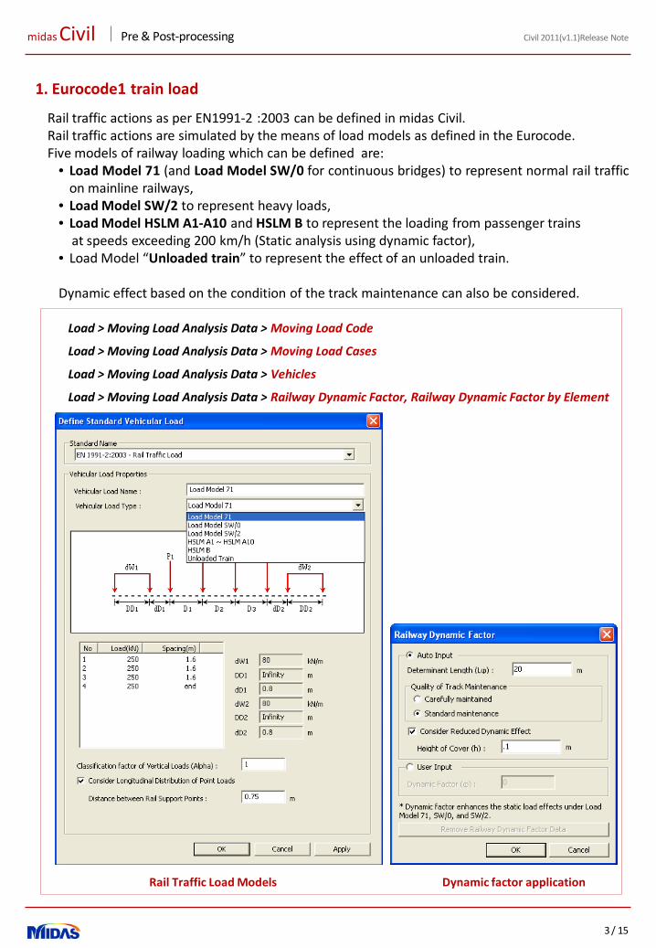
1. Eurocode1 train load
Rail traffic actions as per EN1991-2 :2003 can be defined in midas Civil.Rail traffic actions are simulated by the means of load models as defined in the Eurocode.Five models of railway loading which can be defined are:
• Load Model 71 (and Load Model SW/0 for continuous bridges) to represent normal rail trafficon mainline railways,
• Load Model SW/2 to represent heavy loads,• Load Model HSLM A1-A10 and HSLM B to represent the loading from passenger trains
at speeds exceeding 200 km/h (Static analysis using dynamic factor),• Load Model “Unloaded train” to represent the effect of an unloaded train.
Dynamic effect based on the condition of the track maintenance can also be considered.
Rail Traffic Load Models Dynamic factor application
Load > Moving Load Analysis Data > Vehicles
Load > Moving Load Analysis Data > Moving Load Cases
Load > Moving Load Analysis Data > Moving Load Code
Load > Moving Load Analysis Data > Railway Dynamic Factor, Railway Dynamic Factor by Element
midasCivil Pre & Post-processing
4 / 15
Civil 2011(v1.1)Release Note
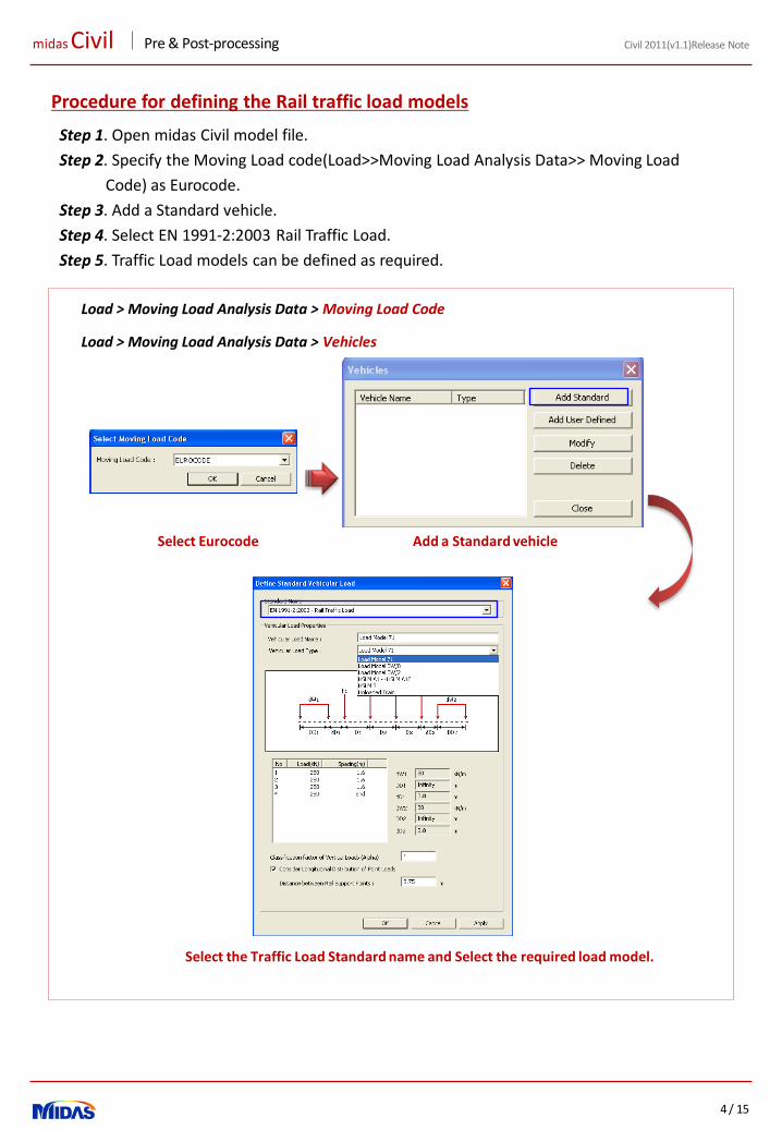
Step 1. Open midas Civil model file.
Step 2. Specify the Moving Load code(Load>>Moving Load Analysis Data>> Moving Load
Code) as Eurocode.
Step 3. Add a Standard vehicle.
Step 4. Select EN 1991-2:2003 Rail Traffic Load.
Step 5. Traffic Load models can be defined as required.
Procedure for defining the Rail traffic load models
Select Eurocode Add a Standard vehicle
Select the Traffic Load Standard name and Select the required load model.
Load > Moving Load Analysis Data > Vehicles
Load > Moving Load Analysis Data > Moving Load Code
midasCivil Pre & Post-processing
5 / 15
Civil 2011(v1.1)Release Note
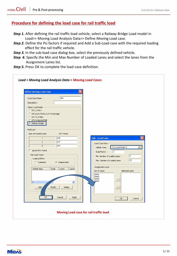
Procedure for defining the load case for rail traffic load
Step 1. After defining the rail traffic load vehicle, select a Railway Bridge Load model inLoad>> Moving Load Analysis Data>> Define Moving Load case.
Step 2. Define the Psi factors if required and Add a Sub-Load case with the required loading effect for the rail traffic vehicle.
Step 3. In the sub-load case dialog box, select the previously defined vehicle.Step 4. Specify the Min and Max Number of Loaded Lanes and select the lanes from the
Assignment Lanes list.Step 5. Press OK to complete the load case definition.
Moving Load case for rail traffic load
Load > Moving Load Analysis Data > Moving Load Cases

midasCivil Pre & Post-processing
6 / 15
Civil 2011(v1.1)Release Note
Procedure for defining the Dynamic Factor
Step 1. Dynamic factor can be applied through Load>>Moving Load analysis Data>>Dynamic
factor.
Step 2. Select the elements on which the dynamic factor has to be applied.
Step 3. The Dynamic factor can be input either manually or Automatically by the program.
If Auto Input is selected, determinant length along with the quality of track
maintenance should be defined. A reduction in dynamic factor due to the cover
thickness can also be considered.
Step 4. The dynamic factors calculated can be checked or modified in the table format using
Load>>Moving Load analysis Data>>Dynamic factor table.
Dynamic factor
Dynamic factor Table
Load > Moving Load Analysis Data > Railway Dynamic Factor, Railway Dynamic Factor by Element
Load > Moving Load Analysis Data > Railway Dynamic Factor by Element Table

midasCivil Pre & Post-processing
7 / 15
Civil 2011(v1.1)Release Note
2. Load Model 3 (Straddling Special Vehicles) as per UK NA to Eurocode 1
Special vehicles (SV/SOV)
midas Civil can now also simulate the vehicles which can straddle between two lanes. These newly added straddling vehicles are as per UK National Annex and include :• Load Model 3 (SV 80)• Load Model 3 (SV 100)• Load Model 3 (SV 196)• Load Model 3 (SOV 250)• Load Model 3 (SOV 350)• Load Model 3 (SOV 450)• Load Model 3 (SOV 600).
Load > Moving Load Analysis Data > Vehicles
Load > Moving Load Analysis Data > Moving Load Cases
Load > Moving Load Analysis Data > Moving Load Code
midasCivil Pre & Post-processing
8 / 15
Civil 2011(v1.1)Release Note
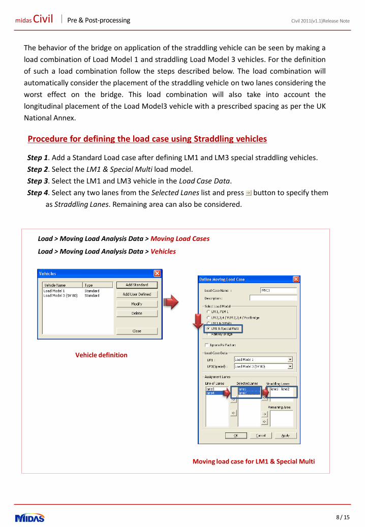
Procedure for defining the load case using Straddling vehicles
Step 1. Add a Standard Load case after defining LM1 and LM3 special straddling vehicles.
Step 2. Select the LM1 & Special Multi load model.
Step 3. Select the LM1 and LM3 vehicle in the Load Case Data.
Step 4. Select any two lanes from the Selected Lanes list and press button to specify them
as Straddling Lanes. Remaining area can also be considered.
Moving load case for LM1 & Special Multi
Vehicle definition
The behavior of the bridge on application of the straddling vehicle can be seen by making a
load combination of Load Model 1 and straddling Load Model 3 vehicles. For the definition
of such a load combination follow the steps described below. The load combination will
automatically consider the placement of the straddling vehicle on two lanes considering the
worst effect on the bridge. This load combination will also take into account the
longitudinal placement of the Load Model3 vehicle with a prescribed spacing as per the UK
National Annex.
Load > Moving Load Analysis Data > Vehicles
Load > Moving Load Analysis Data > Moving Load Cases

midasCivil Pre & Post-processing
9 / 15
Civil 2011(v1.1)Release Note
3. General Shape of Composite Steel Girder Check as per EN 1994-2:2005
• Code check can be performed for any shape of composite section.
• The following checks as per the Ultimate Limit State can be applied:
• Bending Resistance with the classification of cross-section
• Resistance to Vertical Shear considering buckling resistance
• Resistance to Longitudinal Shear
• The following checks as per Service Limit State can be applied:
• Stress limitation (Concrete, Reinforcement, Structural steel)
• Longitudinal shear force per connector
• Sections imported from SPC are supported.
• Longitudinal rebars can be assigned to the composite sections.
• Transverse and longitudinal stiffeners can be assigned and used for code check.
• Due consideration is given to class determination as per Eurocode.
• Design Report can be obtained in the table format or Excel format.
Table For Vertical Shear Resistance Check
Design > Composite Steel Girder Design

midasCivil Pre & Post-processing
10 / 15
Civil 2011(v1.1)Release Note
• Reinforcement can be provided either as line type, point or poly-line type.
• Top Flange, Bottom Flange and Web can be categorized as Internal and outstand members as required by Eurocode.
• Transverse Stiffeners can be provided.
• Transverse Stiffeners at end supports can be assigned as either Rigid End Post, Non Rigid End Post or No End Post.
• Different Transverse Stiffeners can be provided to different supports.
Design > Composite Steel Girder Design > Longitudinal Reinforcement
Definition of Reinforcement
Design > Composite Steel Girder Design > Transverse Stiffener at End Support & Transverse Stiffener
Definition of Transverse Stiffener of End Support
Definition of Transverse Stiffener
midasCivil Pre & Post-processing
11 / 15
Civil 2011(v1.1)Release Note
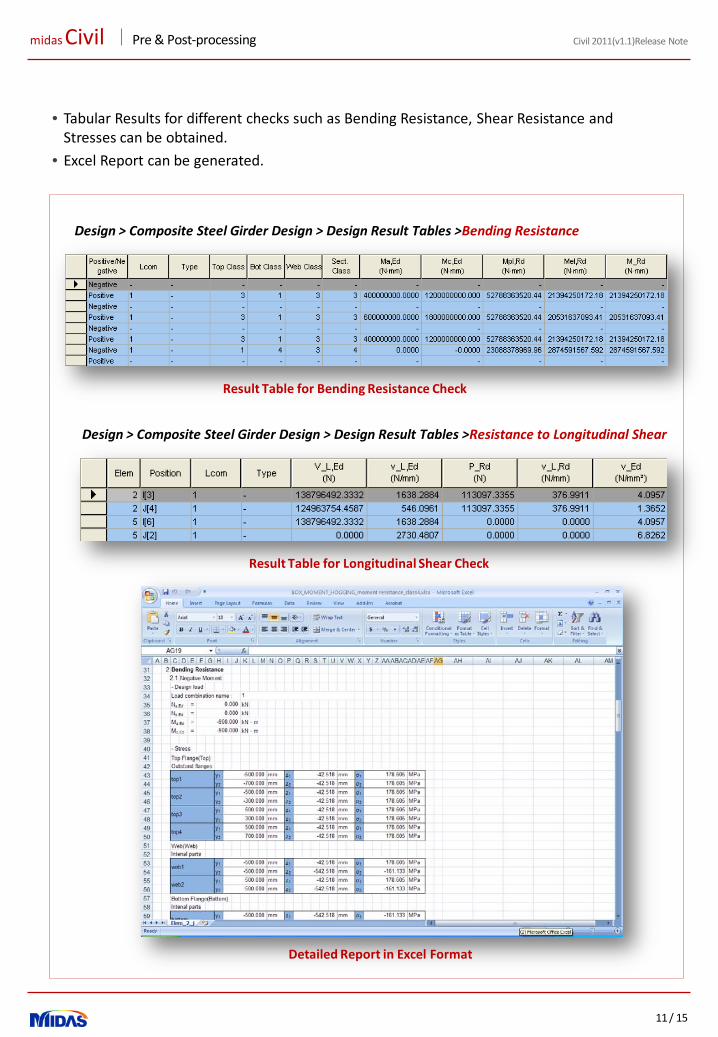
• Tabular Results for different checks such as Bending Resistance, Shear Resistance and Stresses can be obtained.
• Excel Report can be generated.
Design > Composite Steel Girder Design > Design Result Tables >Bending Resistance
Result Table for Bending Resistance Check
Design > Composite Steel Girder Design > Design Result Tables >Resistance to Longitudinal Shear
Result Table for Longitudinal Shear Check
Detailed Report in Excel Format
midasCivil Pre & Post-processing
12 / 15
Civil 2011(v1.1)Release Note
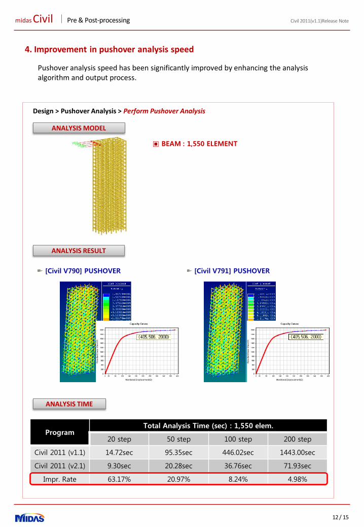
4. Improvement in pushover analysis speed
Design > Pushover Analysis > Perform Pushover Analysis
ANALYSIS MODEL
ANALYSIS RESULT
[Civil V790] PUSHOVER [Civil V791] PUSHOVER
▣ BEAM : 1,550 ELEMENT
ANALYSIS TIME
ProgramTotal Analysis Time (sec) : 1,550 elem.
20 step 50 step 100 step 200 step
Civil 2011 (v1.1) 14.72sec 95.35sec 446.02sec 1443.00sec
Civil 2011 (v2.1) 9.30sec 20.28sec 36.76sec 71.93sec
Impr. Rate 63.17% 20.97% 8.24% 4.98%
Pushover analysis speed has been significantly improved by enhancing the analysis algorithm and output process.
midasCivil Pre & Post-processing
13 / 15
Civil 2011(v1.1)Release Note
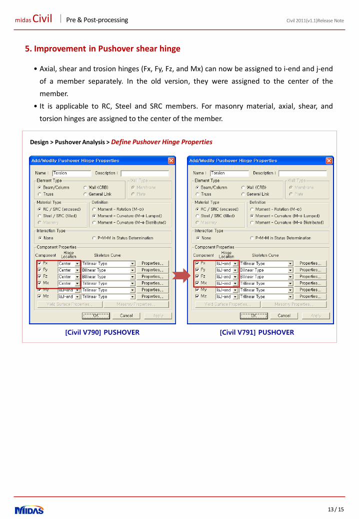
5. Improvement in Pushover shear hinge
• Axial, shear and trosion hinges (Fx, Fy, Fz, and Mx) can now be assigned to i-end and j-end
of a member separately. In the old version, they were assigned to the center of the
member.
• It is applicable to RC, Steel and SRC members. For masonry material, axial, shear, and
torsion hinges are assigned to the center of the member.
Design > Pushover Analysis > Define Pushover Hinge Properties
[Civil V790] PUSHOVER [Civil V791] PUSHOVER
midasCivil Pre & Post-processing
14 / 15
Civil 2011(v1.1)Release Note
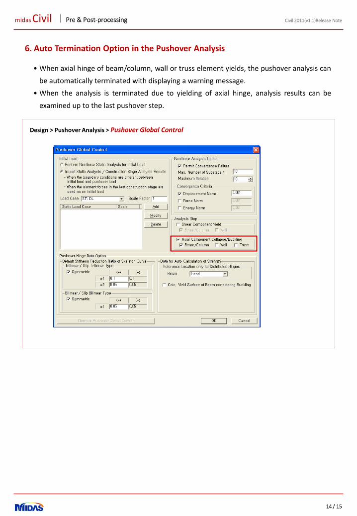
6. Auto Termination Option in the Pushover Analysis
• When axial hinge of beam/column, wall or truss element yields, the pushover analysis can
be automatically terminated with displaying a warning message.
• When the analysis is terminated due to yielding of axial hinge, analysis results can be
examined up to the last pushover step.
Design > Pushover Analysis > Pushover Global Control

midas Civil New Module: GSD
1 / 38
Civil 2011 (v1.1)Release Note
Integrated Solution System for Bridge and Civil Engineering
midas Civil New Module: GSD
2 / 38
Civil 2011 (v1.1)Release Note
Enhancements
Pre/Post Processing
1. Section Manager
2. Improvement in Beam Detail Analysis
3. Tendon DXF Export
and much more …
Analysis
1. Moment-Curvature Calculation
2. Damping Ratios by Material Properties
3. Considering Consistent Mass in Time History Analysis
4. Improvement in Group Damping
And much more…
Design
1. Irregular Section Check as per EC2-2:06
2. MS Excel Report for Composite Plate-Girder design as per EC4
16
25
35
New Module 3
1. General Section Designer
midas Civil New Module: GSD
3 / 38
Civil 2011 (v1.1)Release Note
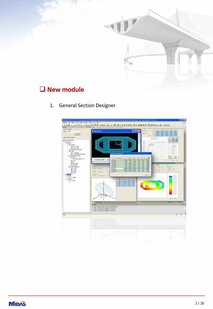
1. General Section Designer
New module
midas Civil New Module: GSD
4 / 38
Civil 2011 (v1.1)Release Note
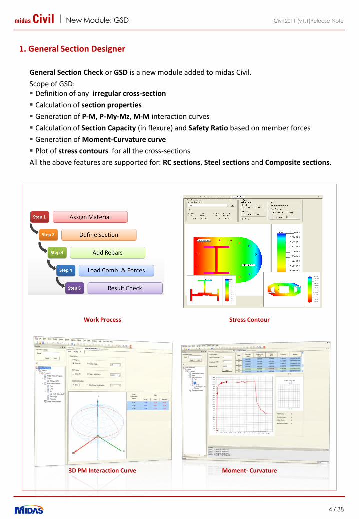
General Section Check or GSD is a new module added to midas Civil.
Scope of GSD: Definition of any irregular cross-section
Calculation of section properties
Generation of P-M, P-My-Mz, M-M interaction curves
Calculation of Section Capacity (in flexure) and Safety Ratio based on member forces
Generation of Moment-Curvature curve
Plot of stress contours for all the cross-sections
All the above features are supported for: RC sections, Steel sections and Composite sections.
1. General Section Designer
Stress ContourWork Process
Moment- Curvature3D PM Interaction Curve
midas Civil New Module: GSD
5 / 38
Civil 2011 (v1.1)Release Note
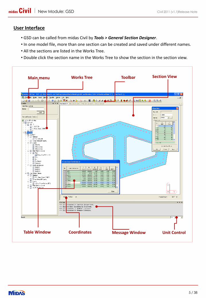
User Interface
• GSD can be called from midas Civil by Tools > General Section Designer.
• In one model file, more than one section can be created and saved under different names.
• All the sections are listed in the Works Tree.
• Double click the section name in the Works Tree to show the section in the section view.
Toolbar
Coordinates
Main menu Works Tree
Message Window Unit ControlTable Window
Section View

midas Civil New Module: GSD
6 / 38
Civil 2011 (v1.1)Release Note
Work Process
Step 1. Define material
• Materials : RC or Steel
• Applied Codes: Eurocode, UNI, British Standard, ASTM, Indian Standard, etc.
• Nonlinear material properties can also be assigned to concrete, structural steel and rebar
materials.
midas Civil New Module: GSD
7 / 38
Civil 2011 (v1.1)Release Note
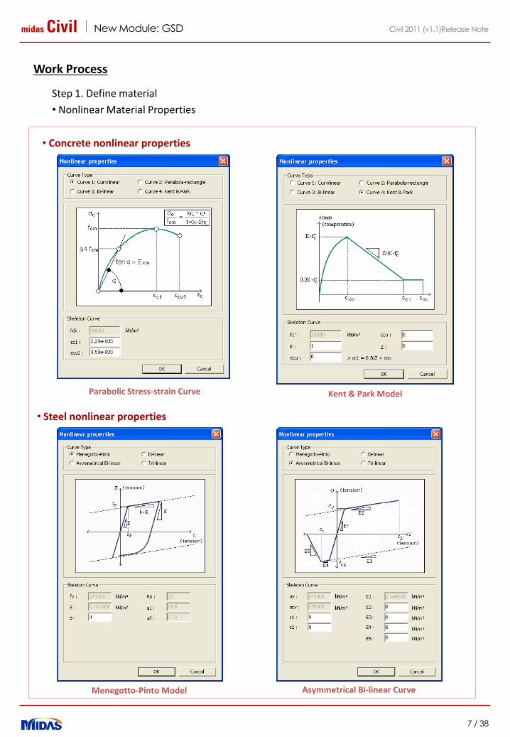
Work Process
Step 1. Define material
• Nonlinear Material Properties
Kent & Park ModelParabolic Stress-strain Curve
Asymmetrical Bi-linear CurveMenegotto-Pinto Model
• Concrete nonlinear properties
• Steel nonlinear properties
midas Civil New Module: GSD
8 / 38
Civil 2011 (v1.1)Release Note
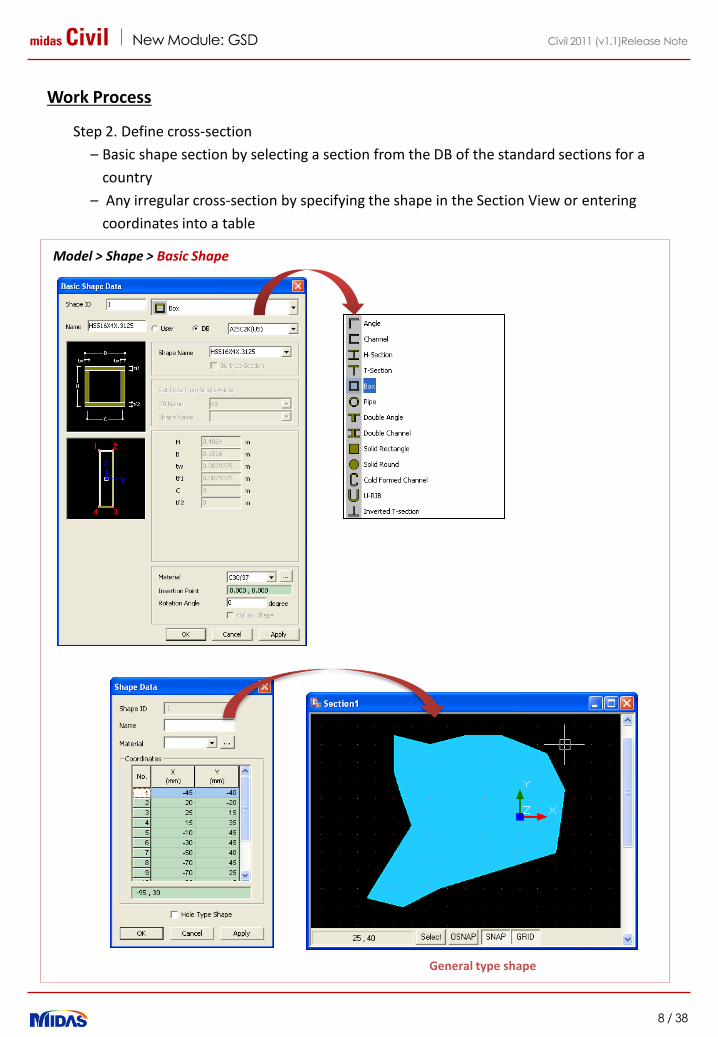
Work Process
Step 2. Define cross-section
– Basic shape section by selecting a section from the DB of the standard sections for a
country
– Any irregular cross-section by specifying the shape in the Section View or entering
coordinates into a table
General type shape
Model > Shape > Basic Shape
midas Civil New Module: GSD
9 / 38
Civil 2011 (v1.1)Release Note
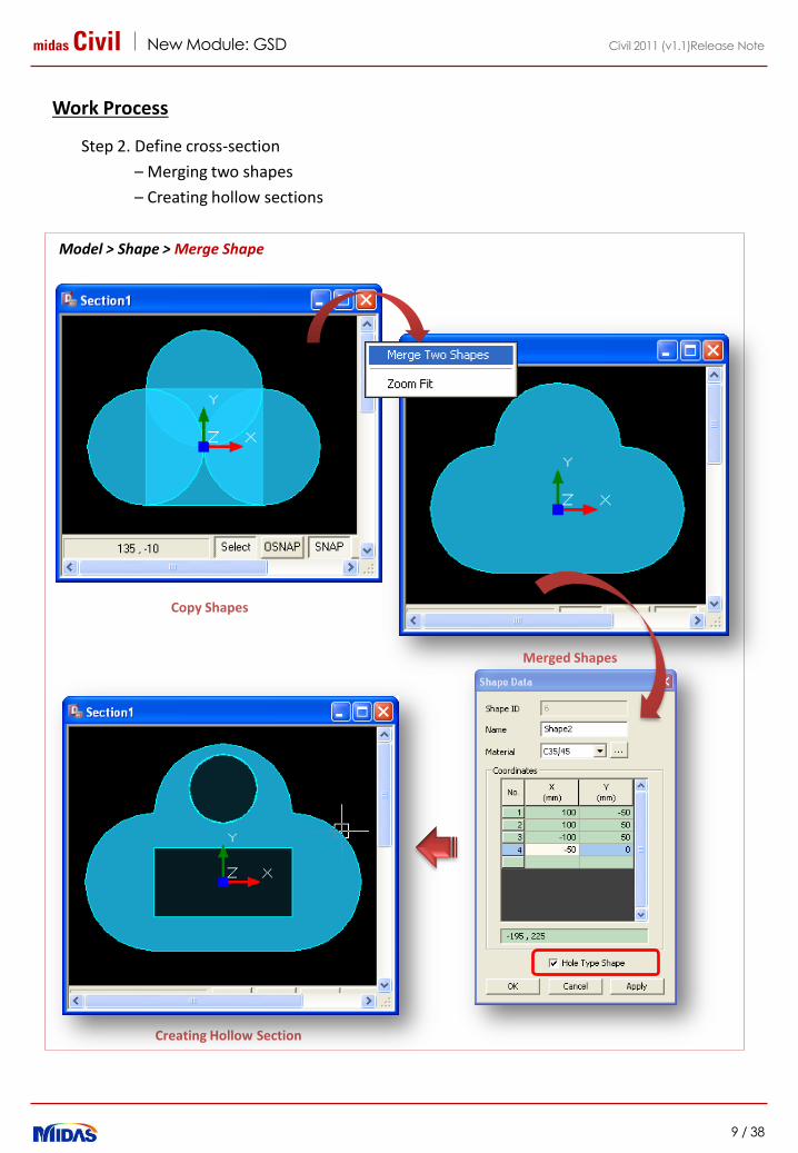
Work Process
Step 2. Define cross-section
– Merging two shapes
– Creating hollow sections
Copy Shapes
Creating Hollow Section
Merged Shapes
Model > Shape > Merge Shape
midas Civil New Module: GSD
10 / 38
Civil 2011 (v1.1)Release Note
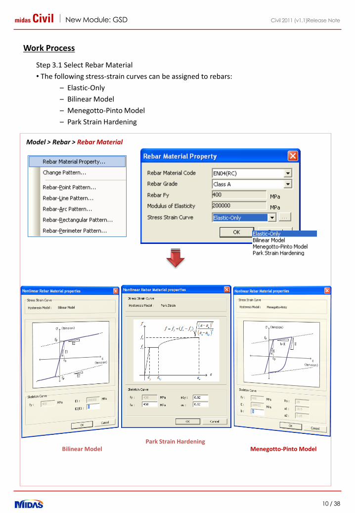
Work Process
Step 3.1 Select Rebar Material
• The following stress-strain curves can be assigned to rebars:
– Elastic-Only
– Bilinear Model
– Menegotto-Pinto Model
– Park Strain Hardening
Menegotto-Pinto ModelPark Strain Hardening
Model > Rebar > Rebar Material
Bilinear Model
midas Civil New Module: GSD
11 / 38
Civil 2011 (v1.1)Release Note
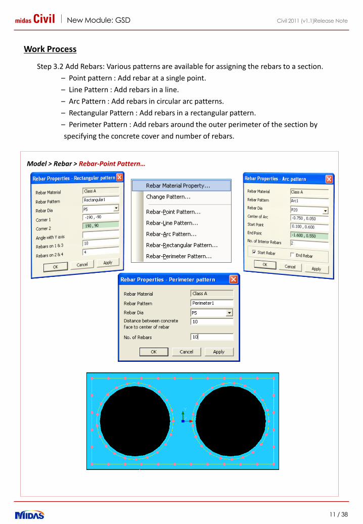
Work Process
Step 3.2 Add Rebars: Various patterns are available for assigning the rebars to a section.
– Point pattern : Add rebar at a single point.
– Line Pattern : Add rebars in a line.
– Arc Pattern : Add rebars in circular arc patterns.
– Rectangular Pattern : Add rebars in a rectangular pattern.
– Perimeter Pattern : Add rebars around the outer perimeter of the section by
specifying the concrete cover and number of rebars.
Model > Rebar > Rebar-Point Pattern…
midas Civil New Module: GSD
12 / 38
Civil 2011 (v1.1)Release Note
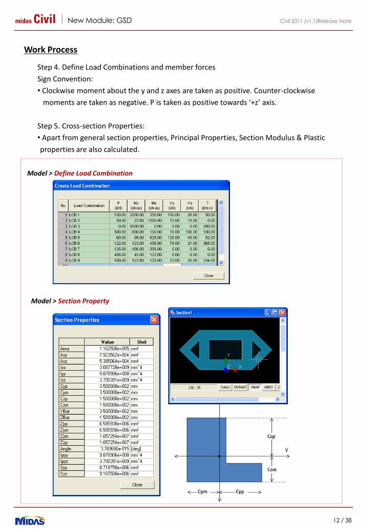
Work Process
Step 4. Define Load Combinations and member forces
Sign Convention:
• Clockwise moment about the y and z axes are taken as positive. Counter-clockwise
moments are taken as negative. P is taken as positive towards ‘+z’ axis.
Step 5. Cross-section Properties:
• Apart from general section properties, Principal Properties, Section Modulus & Plastic
properties are also calculated.
Model > Define Load Combination
Model > Section Property
midas Civil New Module: GSD
13 / 38
Civil 2011 (v1.1)Release Note
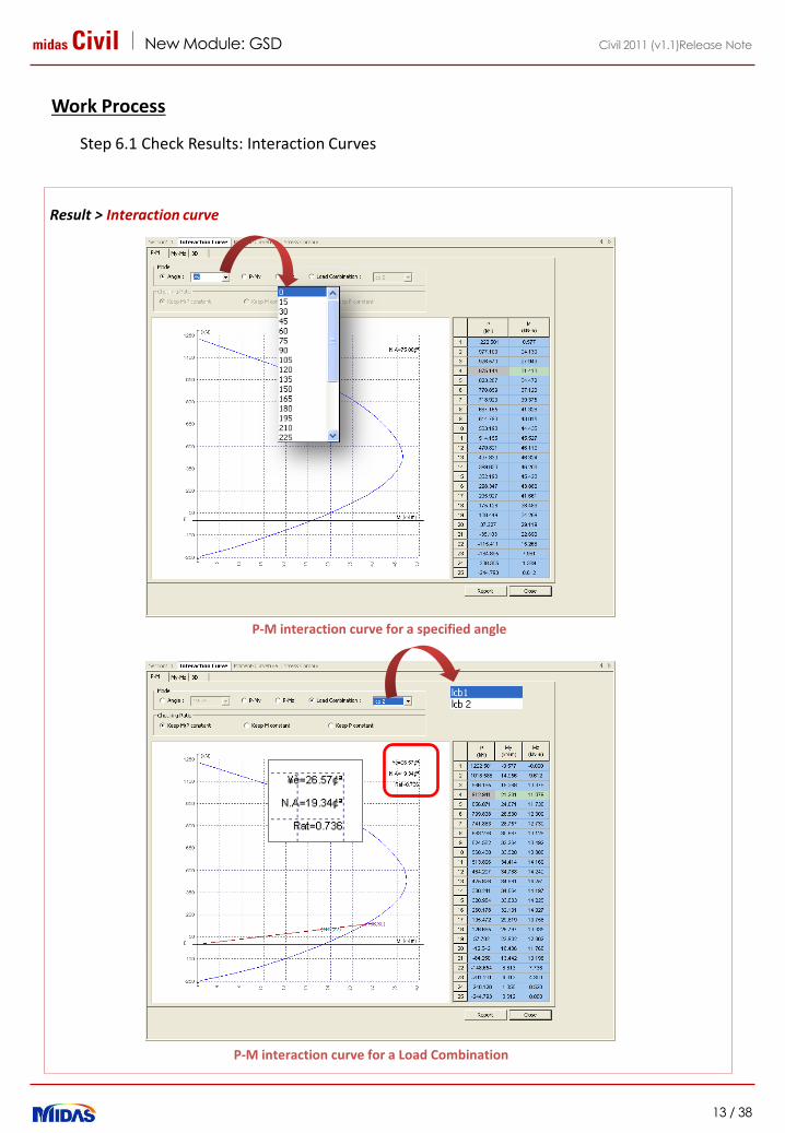
Work Process
Step 6.1 Check Results: Interaction Curves
Result > Interaction curve
P-M interaction curve for a specified angle
P-M interaction curve for a Load Combination

midas Civil New Module: GSD
14 / 38
Civil 2011 (v1.1)Release Note
Work Process
Step 6.1 Check Results: Interaction Curves
Result > Interaction curve
M-M interaction curve for a Load combination
3 D interaction surface showing all the load combination
midas Civil New Module: GSD
15 / 38
Civil 2011 (v1.1)Release Note
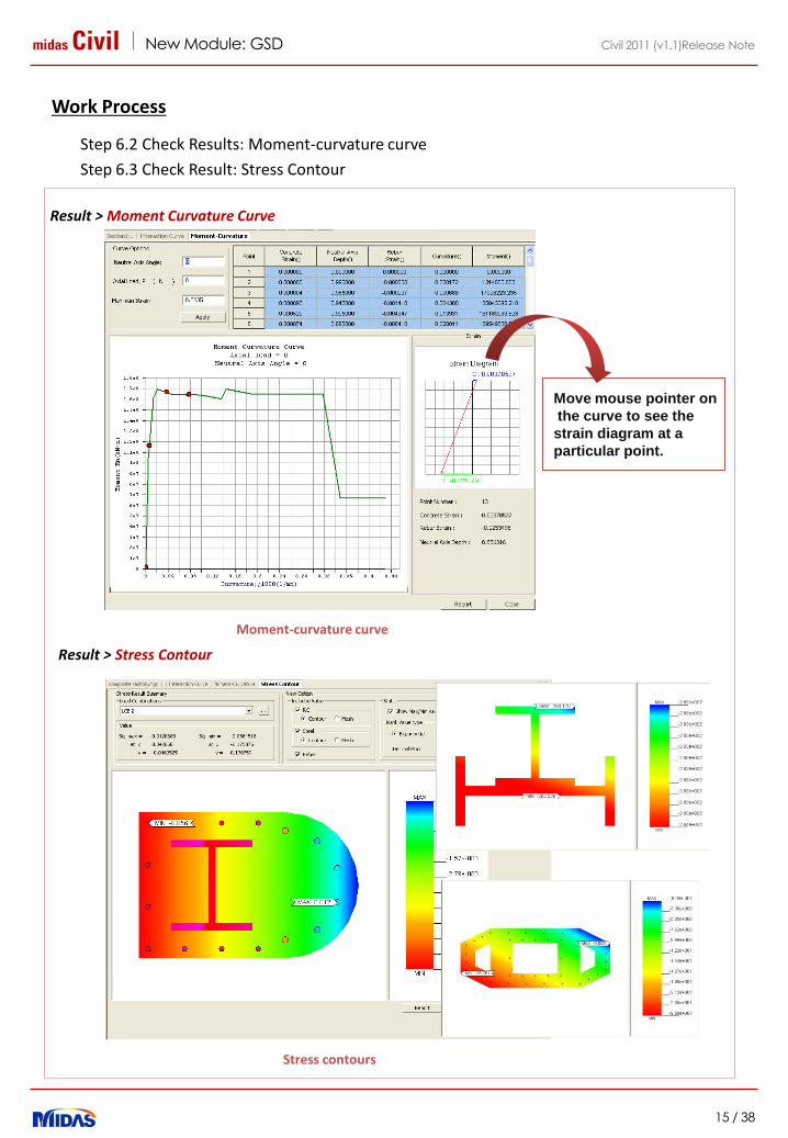
Work Process
Step 6.2 Check Results: Moment-curvature curve
Step 6.3 Check Result: Stress Contour
Result > Moment Curvature Curve
Moment-curvature curve
Stress contours
Move mouse pointer on
the curve to see the
strain diagram at a
particular point.
Result > Stress Contour

midas Civil New Module: GSD
16 / 38
Civil 2011 (v1.1)Release Note
1. Section Manager
2. Improvement in Beam Detail Analysis
3. Tendon DXF Export
4. Improvement in Tendon Profile Generator
5. Addition of Header and Footer in Dynamic Report Generator
6. Improvement in Traffic line-lane and surface-lane display
Pre & Post-processing
midas Civil Pre/Post Processing
17 / 38
Civil 2011 (v1.1)Release Note
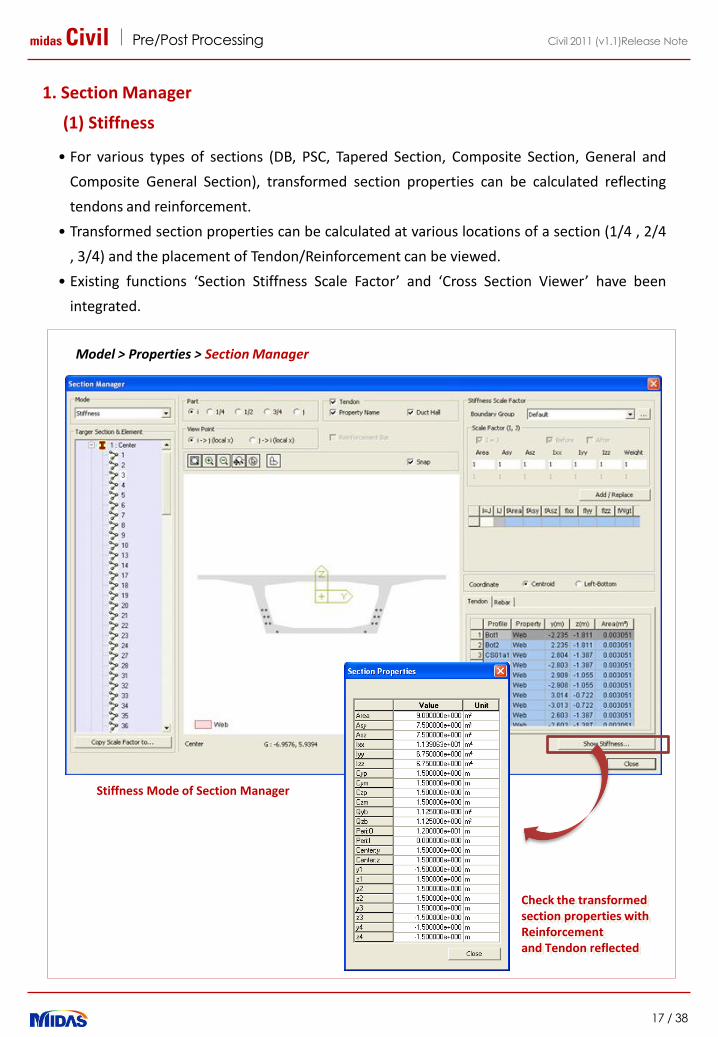
1. Section Manager
(1) Stiffness
• For various types of sections (DB, PSC, Tapered Section, Composite Section, General and
Composite General Section), transformed section properties can be calculated reflecting
tendons and reinforcement.
• Transformed section properties can be calculated at various locations of a section (1/4 , 2/4
, 3/4) and the placement of Tendon/Reinforcement can be viewed.
• Existing functions ‘Section Stiffness Scale Factor’ and ‘Cross Section Viewer’ have been
integrated.
Model > Properties > Section Manager
Stiffness Mode of Section Manager
Check the transformed section properties with Reinforcement and Tendon reflected
midas Civil Pre/Post Processing
18 / 38
Civil 2011 (v1.1)Release Note
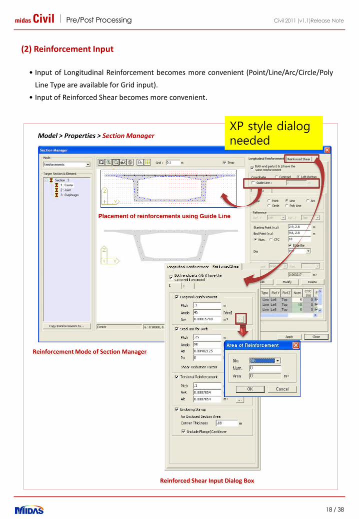
(2) Reinforcement Input
• Input of Longitudinal Reinforcement becomes more convenient (Point/Line/Arc/Circle/Poly
Line Type are available for Grid input).
• Input of Reinforced Shear becomes more convenient.
Model > Properties > Section Manager
Reinforced Shear Input Dialog Box
Reinforcement Mode of Section Manager
XP style dialog needed
Placement of reinforcements using Guide Line
midas Civil Pre/Post Processing
19 / 38
Civil 2011 (v1.1)Release Note
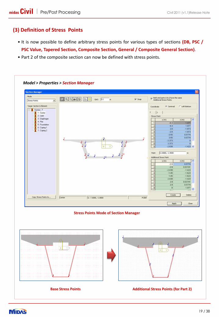
(3) Definition of Stress Points
• It is now possible to define arbitrary stress points for various types of sections (DB, PSC /
PSC Value, Tapered Section, Composite Section, General / Composite General Section).
• Part 2 of the composite section can now be defined with stress points.
Model > Properties > Section Manager
Stress Points Mode of Section Manager
Base Stress Points Additional Stress Points (for Part 2)
midas Civil Pre/Post Processing
20 / 38
Civil 2011 (v1.1)Release Note
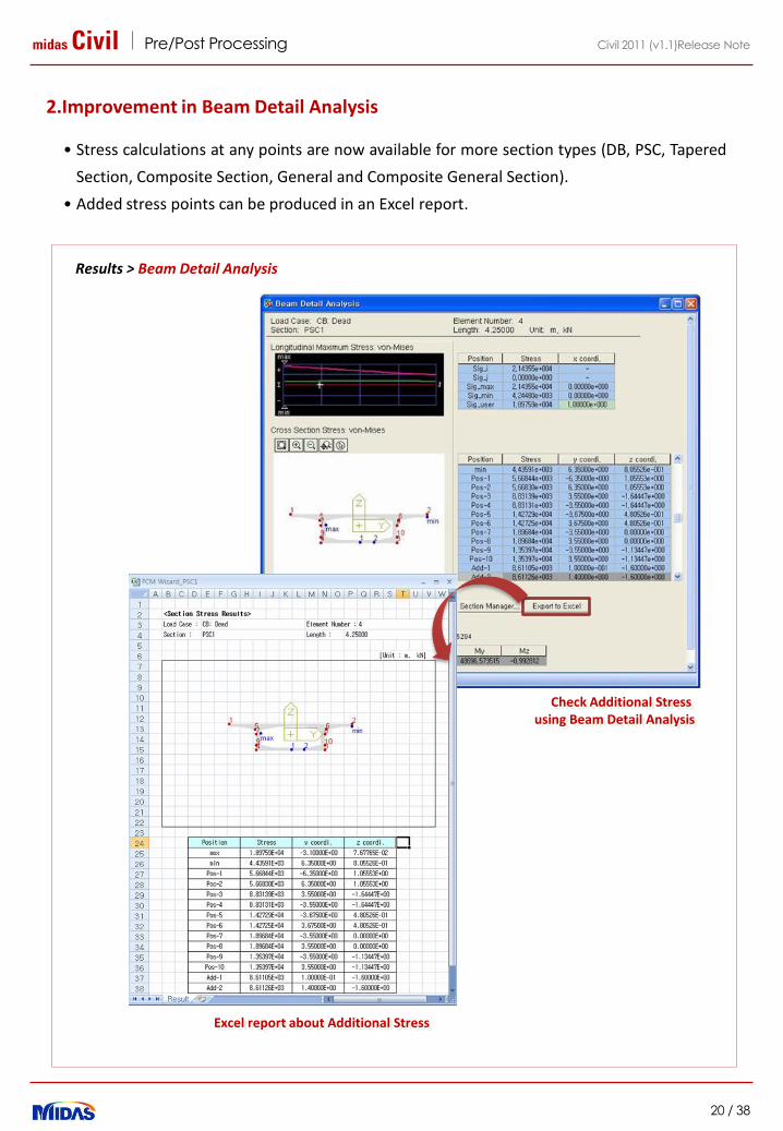
2.Improvement in Beam Detail Analysis
• Stress calculations at any points are now available for more section types (DB, PSC, Tapered
Section, Composite Section, General and Composite General Section).
• Added stress points can be produced in an Excel report.
Results > Beam Detail Analysis
Check Additional Stress using Beam Detail Analysis
Excel report about Additional Stress
midas Civil Pre/Post Processing
21 / 38
Civil 2011 (v1.1)Release Note
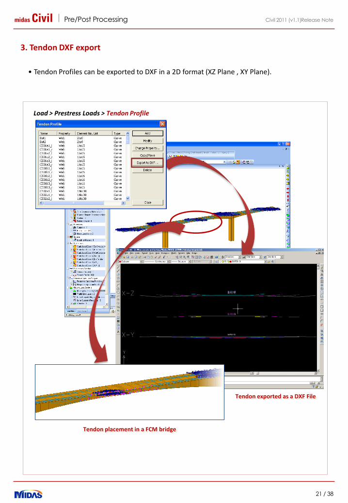
3. Tendon DXF export
• Tendon Profiles can be exported to DXF in a 2D format (XZ Plane , XY Plane).
Load > Prestress Loads > Tendon Profile
Tendon exported as a DXF File
Tendon placement in a FCM bridge
midas Civil Pre/Post Processing
22 / 38
Civil 2011 (v1.1)Release Note
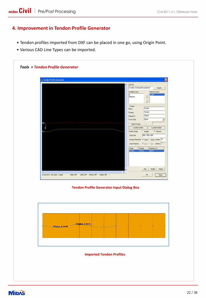
4. Improvement in Tendon Profile Generator
• Tendon profiles imported from DXF can be placed in one go, using Origin Point.
• Various CAD Line Types can be imported.
Tools > Tendon Profile Generator
Imported Tendon Profiles
Tendon Profile Generator Input Dialog Box
midas Civil Pre/Post Processing
23 / 38
Civil 2011 (v1.1)Release Note
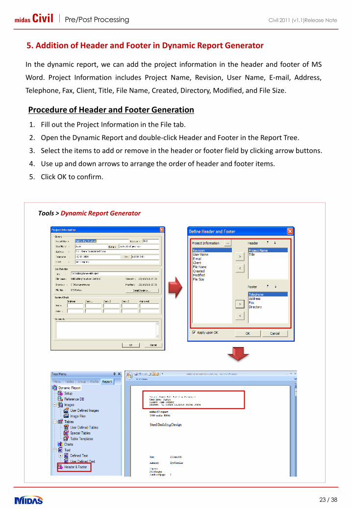
1. Fill out the Project Information in the File tab.
2. Open the Dynamic Report and double-click Header and Footer in the Report Tree.
3. Select the items to add or remove in the header or footer field by clicking arrow buttons.
4. Use up and down arrows to arrange the order of header and footer items.
5. Click OK to confirm.
5. Addition of Header and Footer in Dynamic Report Generator
In the dynamic report, we can add the project information in the header and footer of MS
Word. Project Information includes Project Name, Revision, User Name, E-mail, Address,
Telephone, Fax, Client, Title, File Name, Created, Directory, Modified, and File Size.
Procedure of Header and Footer Generation
Tools > Dynamic Report Generator

midas Civil Pre/Post Processing
24 / 38
Civil 2011 (v1.1)Release Note
8. Improvement in Traffic Line-lane and Surface-lane display
• After displaying the traffic surface lanes, it took long time to change the display of model
view. Now, once the traffic surface lanes have been displayed, the view can be changed
instantly.
• After a first display of the traffic surface lanes, the lanes can be displayed instantly from
the second time of displaying.
• Each lane can be displayed separately.
Display all the lanes at a time
Display one lane at a time

midas Civil Pre/Post Processing
25 / 38
Civil 2011 (v1.1)Release Note
1. Moment-Curvature Calculation
2. Damping Ratios by Material Properties
3. Considering Consistent Mass in Time History Analysis
4. Improvement in Group Damping
5. Considering Static Load Case for the Initial Loading in Time
History Analysis
6. Considering the Construction Stage Load for Initial Loading in
Pushover Analysis
7. Option for cumulating reactions and displacements due to initial
loads in Pushover Analysis
8. Considering Boundary Change Assignment Function in Pushover
Analysis
9. Option for Considering the Shear Failure in Pushover Analysis
10.Addition of Ramberg-Osgood and Hardin-Drnevich Models in
Inelastic Hinge Properties
Analysis
midas Civil Analysis
26 / 38
Civil 2011 (v1.1)Release Note
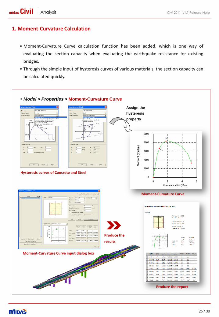
1. Moment-Curvature Calculation
• Moment-Curvature Curve calculation function has been added, which is one way of
evaluating the section capacity when evaluating the earthquake resistance for existing
bridges.
• Through the simple input of hysteresis curves of various materials, the section capacity can
be calculated quickly.
Model > Properties > Moment-Curvature Curve
Hysteresis curves of Concrete and Steel
Produce the report
Moment-Curvature Curve
Moment-Curvature Curve input dialog box
Produce the
results
Assign the
hysteresis
property

midas Civil Analysis
27 / 38
Civil 2011 (v1.1)Release Note
2. Damping Ratios by Material Properties
• An option considering different damping ratios for different materials has been added in
the Material Data for time history analysis and response spectrum analysis.
• In order to apply the damping ratio specified in the Material Data, following damping
method needs to be selected in the Time History Load Cases.
Response Spectrum Analysis : Strain Energy Proportional
Time History Analysis: Element Mass & Stiffness Proportional or Strain Energy Damping
Model > Properties > Material > Add > Damping Ratio
Load > Time History Analysis Data > Time History Load Cases
Default value of damping ratio by material types
- Steel : 0.02 (2%)- Concrete / SRC : 0.05 (5%)- USER : 0.00 (0%)
midas Civil Analysis
28 / 38
Civil 2011 (v1.1)Release Note
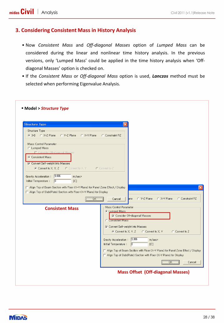
3. Considering Consistent Mass in History Analysis
• Now Consistent Mass and Off-diagonal Masses option of Lumped Mass can be
considered during the linear and nonlinear time history analysis. In the previous
versions, only ‘Lumped Mass’ could be applied in the time history analysis when ‘Off-
diagonal Masses’ option is checked on.
• If the Consistent Mass or Off-diagonal Mass option is used, Lanczos method must be
selected when performing Eigenvalue Analysis.
Model > Structure Type
Consistent Mass
Mass Offset (Off-diagonal Masses)

midas Civil Analysis
29 / 38
Civil 2011 (v1.1)Release Note
4. Improvement in Group Damping
• Group Damping dialog box has been divided into ‘Element Mass & Stiffness
Proportional…’ and ‘Strain Energy Proportional…’.
• Now Mass Coefficient (alpha) can be considered. Coefficients for mass and stiffness
(alpha and beta) are automatically calculated.
Model > Properties > Group Damping : Element Mass & Stiffness Proportional
Model > Properties > Group Damping : Strain Energy Proportional
Element Mass & Stiffness Proportional
Strain Energy Proportional
midas Civil Analysis
30 / 38
Civil 2011 (v1.1)Release Note
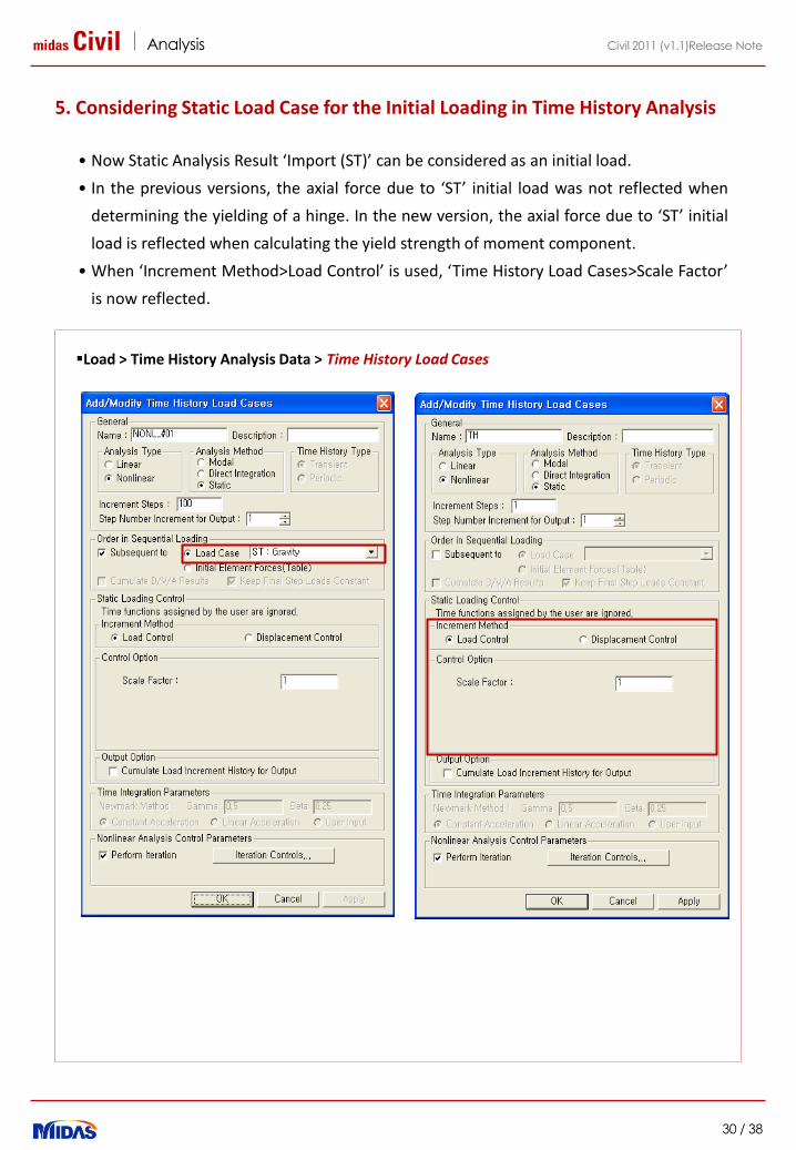
5. Considering Static Load Case for the Initial Loading in Time History Analysis
• Now Static Analysis Result ‘Import (ST)’ can be considered as an initial load.
• In the previous versions, the axial force due to ‘ST’ initial load was not reflected when
determining the yielding of a hinge. In the new version, the axial force due to ‘ST’ initial
load is reflected when calculating the yield strength of moment component.
• When ‘Increment Method>Load Control’ is used, ‘Time History Load Cases>Scale Factor’
is now reflected.
Load > Time History Analysis Data > Time History Load Cases
midas Civil Analysis
31 / 38
Civil 2011 (v1.1)Release Note
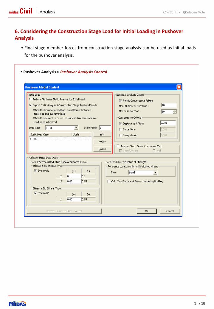
6. Considering the Construction Stage Load for Initial Loading in Pushover Analysis
• Final stage member forces from construction stage analysis can be used as initial loads
for the pushover analysis.
Pushover Analysis > Pushover Analysis Control
midas Civil Analysis
32 / 38
Civil 2011 (v1.1)Release Note
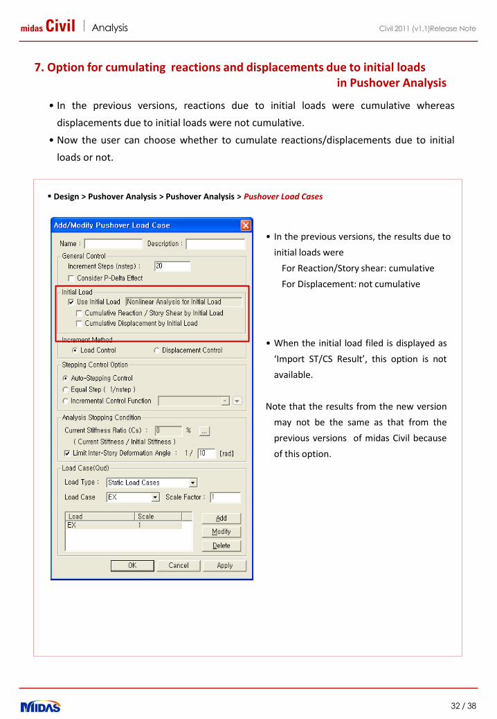
7. Option for cumulating reactions and displacements due to initial loads in Pushover Analysis
• In the previous versions, reactions due to initial loads were cumulative whereas
displacements due to initial loads were not cumulative.
• Now the user can choose whether to cumulate reactions/displacements due to initial
loads or not.
Design > Pushover Analysis > Pushover Analysis > Pushover Load Cases
• When the initial load filed is displayed as
‘Import ST/CS Result’, this option is not
available.
Note that the results from the new version
may not be the same as that from the
previous versions of midas Civil because
of this option.
• In the previous versions, the results due to
initial loads were
For Reaction/Story shear: cumulative
For Displacement: not cumulative

midas Civil Analysis
33 / 38
Civil 2011 (v1.1)Release Note
8. Considering Boundary Change Assignment Function in Pushover Analysis
• This function can be applied to the following condition:
- When the boundary condition of the initial loading is different from that of the pushover loading
- When the section stiffness scale factor assigned for the initial loading is different from that of the
pushover loading
Analysis > Boundary Change Assignment to Load Cases/Analyses

midas Civil Analysis
34 / 38
Civil 2011 (v1.1)Release Note
9. Option for Considering the Shear Failure in Pushover Analysis
• New option for considering the shear component failure has been added. When the option is
selected, the analysis will automatically terminate if the shear hinge occurs in the selected
member type.
Design > Pushover Analysis > Pushover Global Control

midas Civil Analysis
35 / 38
Civil 2011 (v1.1)Release Note
10. Addition of Ramberg-Osgood and Hardin-Drnevich Models in Inelastic Hinge Properties
• Two material models have been added to the Inelastic Hinge Properties (Ramberg-
Osgood, Hardin-Drnevich)
• It can be applied for the inelastic time history analysis of the soil.
Model > Properties > Inelastic Hinge Properties
Ramberg-Osgood, Hardin-Drnevich
Hysteresis Curve

midas Civil Analysis
36 / 38
Civil 2011 (v1.1)Release Note
1. Irregular Section Check as per EC2-2:06
2. MS Excel Report for Composite Plate-Girder design as per EC4
Design

midas Civil Design
37 / 38
Civil 2011 (v1.1)Release Note
1. Irregular Section Check as per EC2-2:06
Design > Concrete Design > Column General Section Data for Checking
Graphic design report 3D interaction surface
Assign rebar to irregular section
• Any column with an irregular section can be checked as per EUROCODE2-2: 06 at Ultimate Limit State for moment and shear.
• Sections imported from AutoCAD or SPC can be checked.
• Point, linear, and circular type rebars can be assigned to the irregular section.
Design > Concrete Design > Concrete Code Check > Column Checking
midas Civil Design
38 / 38
Civil 2011 (v1.1)Release Note
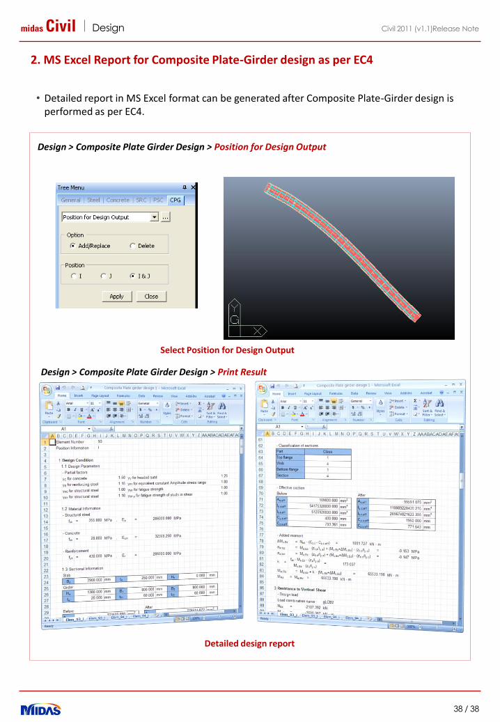
2. MS Excel Report for Composite Plate-Girder design as per EC4
Design > Composite Plate Girder Design > Position for Design Output
Detailed design report
Select Position for Design Output
• Detailed report in MS Excel format can be generated after Composite Plate-Girder design is performed as per EC4.
Design > Composite Plate Girder Design > Print Result

midas Civil Pre & Post-processing
1 / 13
Civil 2010 (v2.1)Release Note
Integrated Solution System for Bridge and Civil Engineering

midas Civil Pre & Post-processing
2 / 13
Civil 2010 (v2.1)Release Note
Enhancements
Pre/Post Processing
1. Dynamic Report Generation
2. Addition of Concurrent Reaction for BD37-01 Vehicle Load
3. Pressure Type of Beam Loads
4. Improved Eccentricity Option in the Element Beam Load and Line Beam Load
5. Improved India Standard section DB
Analysis
1. Mander Model in Inelastic Material Properties
2. Improved MINEGOTTO-PINTO Steel Model
3. Improved Pushover Analysis Result
Design
1. Addition of EUROCODE PSC Design
3
10
13
midas Civil Pre & Post-processing
3 / 13
Civil 2010 (v2.1)Release Note
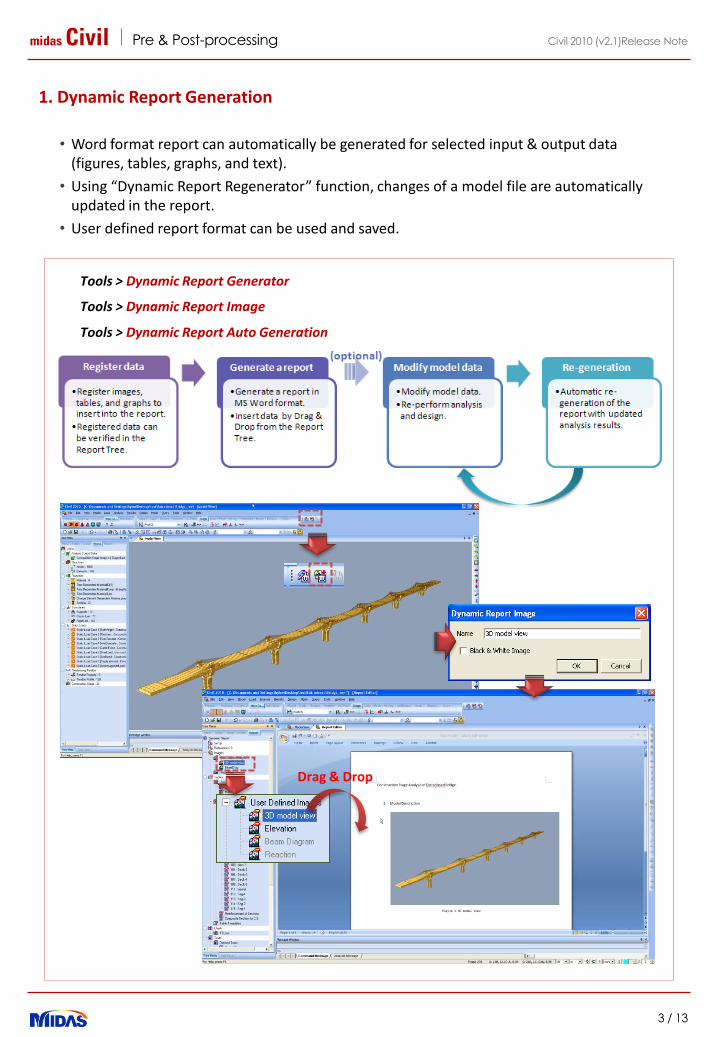
• Word format report can automatically be generated for selected input & output data (figures, tables, graphs, and text).
• Using “Dynamic Report Regenerator” function, changes of a model file are automatically updated in the report.
• User defined report format can be used and saved.
1. Dynamic Report Generation
Drag & Drop
Tools > Dynamic Report Generator
Tools > Dynamic Report Image
Tools > Dynamic Report Auto Generation

midas Civil Pre & Post-processing
4 / 13
Civil 2010 (v2.1)Release Note
Step 1. Open midas Civil model file.
Step 2. Register contents(image, table, chart, summary…) to enter them in the report.
Registered contents are displayed in the Report Tree.
Step 3. Open a new report.
Step 4. Enter the contents by Drag & Drop from report tree.
Step 5. Modify the report file if required.
Procedure for Dynamic Report Generation
Register a image
Insert contents by Drag & Drop
Open a new report
Register a table
Report Tree
midas Civil Pre & Post-processing
5 / 13
Civil 2010 (v2.1)Release Note
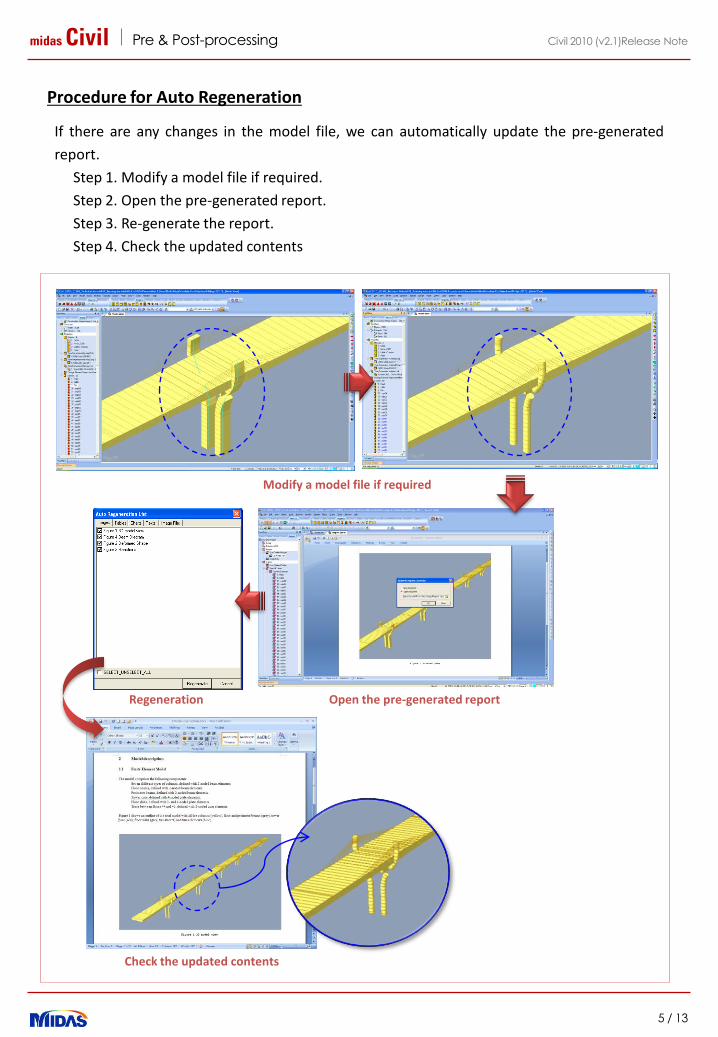
Procedure for Auto Regeneration
Open the pre-generated report
Modify a model file if required
Regeneration
Check the updated contents
If there are any changes in the model file, we can automatically update the pre-generated
report.
Step 1. Modify a model file if required.
Step 2. Open the pre-generated report.
Step 3. Re-generate the report.
Step 4. Check the updated contents

midas Civil Pre & Post-processing
6 / 13
Civil 2010 (v2.1)Release Note
2. Addition of Concurrent Reaction for BD37-01 Vehicle Load
• “Concurrent Reactions” can now be calculated for BD37-01 Vehicle load.
• Generally, the reactions or member forces calculated due to moving load analysis are the
Max/Min values for each reaction values (ex. FX, FY, ... etc.). However, for the support nodes
included in the Concurrent Reaction Group, the concurrent reactions are calculated.
Result > Result table > Concurrent (Max/Min) Reaction
BD37-01 VehicleConcurrent Reaction Group
Concurrent Reaction Result Table
midas Civil Pre & Post-processing
7 / 13
Civil 2010 (v2.1)Release Note
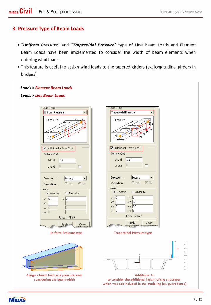
3. Pressure Type of Beam Loads
• “Uniform Pressure” and “Trapezoidal Pressure” type of Line Beam Loads and Element
Beam Loads have been implemented to consider the width of beam elements when
entering wind loads.
• This feature is useful to assign wind loads to the tapered girders (ex. longitudinal girders in
bridges).
Additional H to consider the additional height of the structures
which was not included in the modeling (ex. guard fence)
Assign a beam load as a pressure load considering the beam width
Loads > Element Beam Loads
Loads > Line Beam Loads
Uniform Pressure type Trapezoidal Pressure type
midas Civil Pre & Post-processing
8 / 13
Civil 2010 (v2.1)Release Note
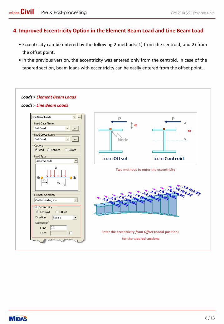
4. Improved Eccentricity Option in the Element Beam Load and Line Beam Load
• Eccentricity can be entered by the following 2 methods: 1) from the centroid, and 2) from
the offset point.
• In the previous version, the eccentricity was entered only from the centroid. In case of the
tapered section, beam loads with eccentricity can be easily entered from the offset point.
Loads > Element Beam Loads
Loads > Line Beam Loads
Enter the eccentricity from Offset (nodal position)
for the tapered sections
Two methods to enter the eccentricity

midas Civil Pre & Post-processing
9 / 13
Civil 2010 (v2.1)Release Note
5. Improved India Standard section DB
• New sections (Box, Pipe, and Angle) have been implemented in IS, IS1161, and IS808
section DB.
Model > Properties > Section
Box Section SHS
Pipe Section NB
Box Section RHS
Angle Section Data

midas Civil Analysis
10 / 13
Civil 2010 (v2.1)Release Note
1. Mander Model in Inelastic Material Properties
• Mander Model has been added to model the behavior of concrete confined with steel
stirrups.
• The menu name, Fiber Material Properties, has been changed to Inelastic Material
Properties.
Model > Properties > Inelastic Material Properties
midas Civil Analysis
11 / 13
Civil 2010 (v2.1)Release Note
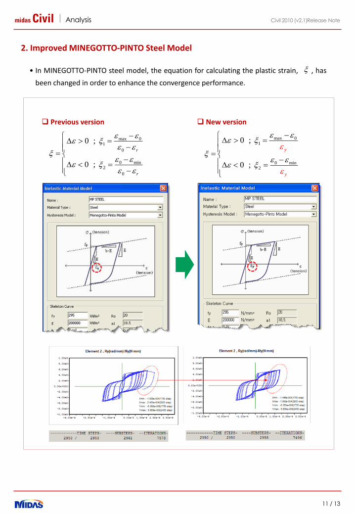
• In MINEGOTTO-PINTO steel model, the equation for calculating the plastic strain, , has
been changed in order to enhance the convergence performance.
max 01
0
0 min2
0
0 ;
0 ;
r
r
max 01
0 min2
0 ;
0 ;
y
y
Previous version New version
2. Improved MINEGOTTO-PINTO Steel Model
midas Civil Analysis
12 / 13
Civil 2010 (v2.1)Release Note
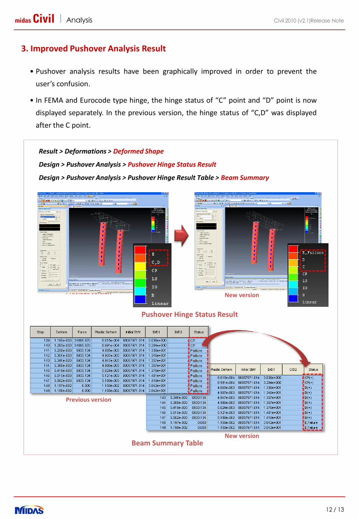
• Pushover analysis results have been graphically improved in order to prevent the
user’s confusion.
• In FEMA and Eurocode type hinge, the hinge status of “C” point and “D” point is now
displayed separately. In the previous version, the hinge status of “C,D” was displayed
after the C point.
Result > Deformations > Deformed Shape
Design > Pushover Analysis > Pushover Hinge Status Result
Design > Pushover Analysis > Pushover Hinge Result Table > Beam Summary
Previous version New version
Beam Summary Table
Pushover Hinge Status Result
Previous version
New version
3. Improved Pushover Analysis Result
midas Civil Design
13 / 13
Civil 2010 (v2.1)Release Note
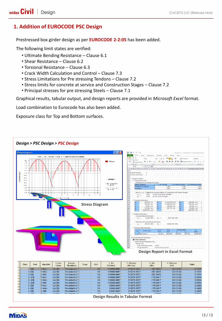
1. Addition of EUROCODE PSC Design
Design > PSC Design > PSC Design
Prestressed box girder design as per EUROCODE 2-2:05 has been added.
The following limit states are verified:
• Ultimate Bending Resistance – Clause 6.1• Shear Resistance – Clause 6.2• Torsional Resistance – Clause 6.3• Crack Width Calculation and Control – Clause 7.3• Stress Limitations for Pre stressing Tendons – Clause 7.2• Stress limits for concrete at service and Construction Stages – Clause 7.2• Principal stresses for pre stressing Steels – Clause 7.1
Graphical results, tabular output, and design reports are provided in Microsoft Excel format.
Load combination to Eurocode has also been added.
Exposure class for Top and Bottom surfaces.
Design Report in Excel Format
Design Results in Tabular Format
Stress Diagram