cl series centrifugal fire pumps installation instructions · cl series centrifugal fire pumps...
TRANSCRIPT

CL Series Centrifugal Fire Pumps
Installation Instructions
Read through the safety information and operating instructions carefully before using your Waterous Fire
Pump.
F-1031, Section 3020 (4/10/17)
Waterous Company, 125 Hardman Avenue South, South St. Paul, Minnesota 55075 USA (651) 450-5000
www.waterousco.com
Table of Contents
Safety Information .................................................................. 1
Introduction ............................................................................... 2
Pump Mounting ....................................................................... 2
Pump Mounting-CLK Series (Optional Mounting Brackets) 3
Optional Suspension Pin Mounting Kit (K520)…………………..4
Pump Mounting – CLT Series ............................................ …5
Pump Mounting – CLD Series ................................................ 6
Pump Mounting – CLPA Series ............................................. 7
Installation of Foam Manager ................................................ 8
Optional Corrosion Protections ............................................ 8
Final Checks............................................................................ 9
Lubrication:
K Transmission ................................................................... 9
T Transmission ................................................................... 9
PA Transmission ................................................................. 9
Testing ...................................................................................... 9

F-1031, Section 3020 Page 1 of 9
WARNING
Death or serious personal injury might occur if proper operating procedures are not followed. The pump operator, as well as individuals connecting supply or discharge hoses to the apparatus must be familiar with these pump operating instructions as well as other operating instructions and manuals for the apparatus, water hydraulics and component limitation.
WARNING
Pressure Hazard. May result in personal injury.
Prior to connection or removal of hoses, caps or other closure with pump intake or pump discharge connections, relieve pressure by opening drains or bleeder valves. Bleeder valves should also be used while filling a hose connected to an intake with water.
WARNING
Scalding Water Hazard. May result in serious burns.
When operating the pump, be sure to open at least one discharge valve slightly to prevent the pump from overheating. If the pump runs for a few minutes completely closed, it may heat the water enough to scald someone when the valve is opened. Overheating can damage the packing, seals and other pump parts. If the apparatus builder has installed a by-pass system or other provision designed to prevent overheating, opening a discharge valve may be unnecessary.
WARNING
Rotating Parts Hazard or Unexpected Truck Movement. May result in serious personal injury or death.
Stop the engine, set parking brake and chock the wheels before going under the truck to adjust packing or to check packing gland temperatures.
OEM Installation Warning
WARNING
Unexpected Truck Movement. May result in serious personal injury or death.
Failure to properly install the pump shift control and pump shift indicator system in the apparatus or failure to incorporate in the Pump Operator’s Panel Engine Speed Interlock System may result in unexpected truck movement which may result in serious personal injury or death.
WARNING
Inability to Pump Water. May result in personal injury or death.
Failure to properly install the pump shift control and pump shift indicator system in the apparatus or failure to incorporate in the Pump Operator’s Panel Engine Speed Interlock System may result in unexpected truck movement which may result in serious personal injury or stress.
WARNING
Exceeding Power Train Torque Ratings. May result in inability to pump water causing serious personal injury or death.
This fire pump may have the capability under certain pumping conditions to exceed the torque rating of the powertrain.
A means to control the engine output to a torque level no greater than the power train’s continuous-duty torque rating must be considered when specifying power train components and engine control system parameters.
Read through and communicate safety information to the end user of this Waterous Fire Pump.
Safety Information
F-1031, Section 3020 Page 2 of 9
Model Descriptions
CLR Intake: 4 in. NH or BSP thread Discharge: Head with 2-1/2 in. flanges, 3 in. NPT tapped
flange, 3 in. Victaulic® or blank (without head
or tapped flange or Victaulic® fitting)
CLV Intake: 4 in. Victaulic®
Discharge: Head with 2-1/2 in. flanges, 3 in. NPT tapped flange, 3 in. Victaulic® or blank (without head
or tapped flange or Victaulic® fitting)
CLD Direct drive with automatic piston primers. Intake: 4 in. or 4-1/2 in. flanged or threaded
Discharge: 3 in NPT tapped flange or blank
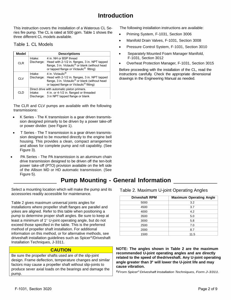
Introduction
This instruction covers the installation of a Waterous CL Se‐ ries fire pump. The CL is rated at 500 gpm. Table 1 shows the three different CL models available.
Table 1. CL Models
The following installation instructions are available:
Priming System, F-1031, Section 3006
Manifold Drain Valves, F-1031, Section 3008
Pressure Control System, F-1031, Section 3010
Separately Mounted Foam Manager Manifold, F-1031, Section 3012
Overheat Protection Manager, F-1031, Section 3015
Before proceeding with the installation of the CL, read the instructions carefully. Check the appropriate dimensional drawings in the Engineering Manual as needed.
The CLR and CLV pumps are available with the following transmissions:
K Series - The K transmission is a gear driven transmis‐ sion designed primarily to be driven by a power take-off or power divider. (see Figure 1).
T Series - The T transmission is a gear driven transmis‐ sion designed to be mounted directly to the engine bell housing. This provides a clean, compact arrangement and allows for complete pump and roll capability. (See Figure 3).
PA Series - The PA transmission is an aluminum chain drive transmission designed to be driven off the ten-bolt power take-off (PTO) provision available on the left side of the Allison MD or HD automatic transmission. (See Figure 5).
Pump Mounting - General Information Select a mounting location which will make the pump and its accessories readily accessible for maintenance.
Table 2 gives maximum universal joints angles for installations where propeller shaft flanges are parallel and yokes are aligned. Refer to this table when positioning a pump to determine proper shaft angles. Be sure to keep at
least a minimum of 1 U-joint operating angle, but do not exceed those specified in the table. This is the preferred method of propeller shaft installation. For additional information on this method, or for alternative methods, see driveshaft installation guidelines such as Spicer®/Driveshaft Installation Techniques, J-3311.
Table 2. Maximum U-joint Operating Angles
Driveshaft RPM Maximum Operating Angle
5000 3.2
4500 3.7
4000 4.2
3500 5.0
3000 5.8
2500 7.0
2000 8.7
1500 11.5
NOTE: The angles shown in Table 2 are the maximum recommended U-joint operating angles and are directly related to the speed of the
driveshaft. Any U-joint operating
angle greater than 3 will lower the U-joint life and may cause vibration. 1From Spicer© Driveshaft Installation Techniques, Form J-3311.
CAUTION Be sure the propeller shafts used are of the slip-joint
design. Frame deflection, temperature changes and similar
factors may cause a propeller shaft without slip-joints to
produce sever axial loads on the bearings and damage the
pump.
F-1031, Section 3020 Page 3 of 9
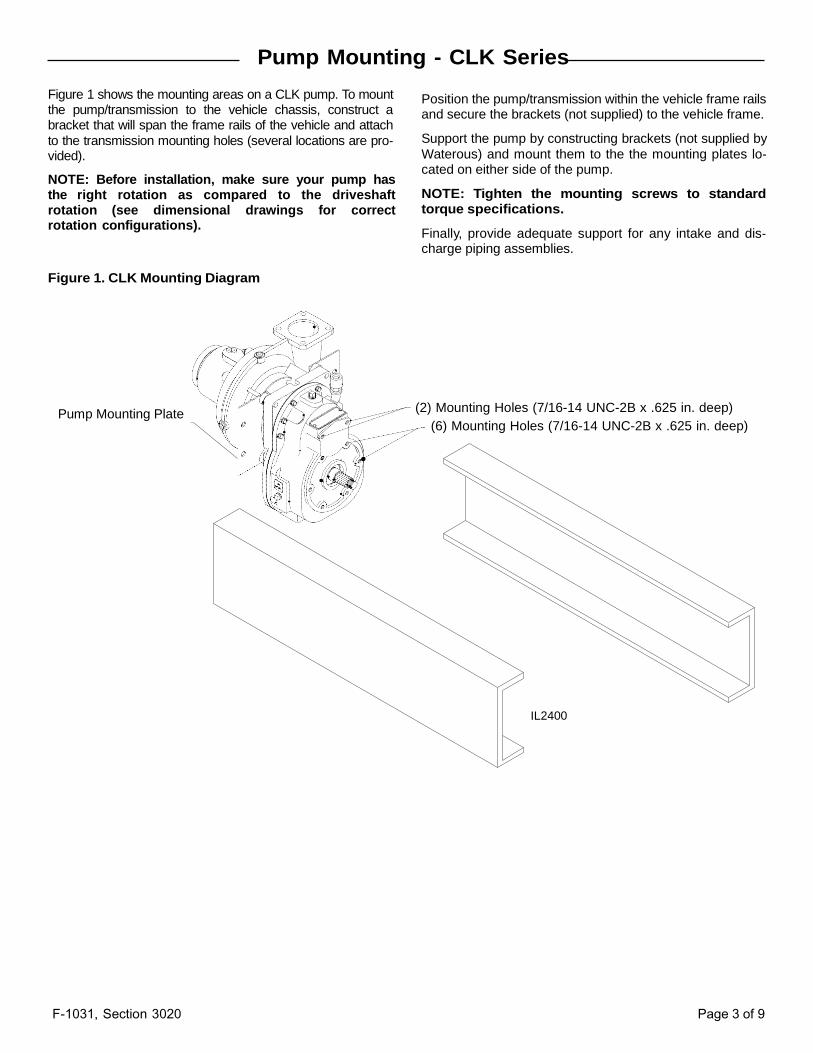
Pump Mounting - CLK Series Figure 1 shows the mounting areas on a CLK pump. To mount the pump/transmission to the vehicle chassis, construct a bracket that will span the frame rails of the vehicle and attach
to the transmission mounting holes (several locations are pro‐ vided).
NOTE: Before installation, make sure your pump has the right rotation as compared to the driveshaft rotation (see dimensional drawings for correct rotation configurations).
Position the pump/transmission within the vehicle frame rails and secure the brackets (not supplied) to the vehicle frame.
Support the pump by constructing brackets (not supplied by
Waterous) and mount them to the the mounting plates lo‐ cated on either side of the pump.
NOTE: Tighten the mounting screws to standard torque specifications.
Finally, provide adequate support for any intake and dis‐ charge piping assemblies.
Figure 1. CLK Mounting Diagram
Pump Mounting Plate (2) Mounting Holes (7/16-14 UNC-2B x .625 in. deep)
(6) Mounting Holes (7/16-14 UNC-2B x .625 in. deep)
IL2400
F-1031, Section 3020 Page 4 of 9
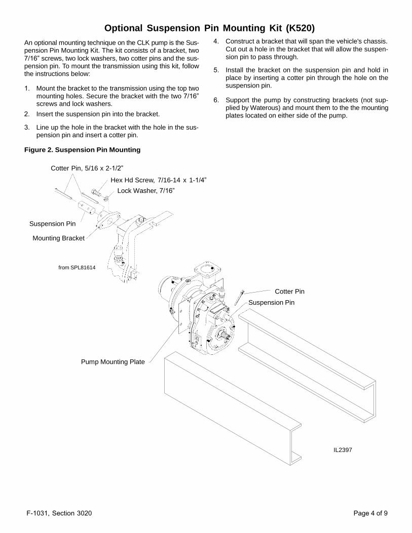
Optional Suspension Pin Mounting Kit (K520)
An optional mounting technique on the CLK pump is the Sus‐ pension Pin Mounting Kit. The kit consists of a bracket, two
7/16” screws, two lock washers, two cotter pins and the sus‐ pension pin. To mount the transmission using this kit, follow the instructions below:
1. Mount the bracket to the transmission using the top two mounting holes. Secure the bracket with the two 7/16” screws and lock washers.
2. Insert the suspension pin into the bracket.
3. Line up the hole in the bracket with the hole in the sus‐ pension pin and insert a cotter pin.
4. Construct a bracket that will span the vehicle's chassis.
Cut out a hole in the bracket that will allow the suspen‐ sion pin to pass through.
5. Install the bracket on the suspension pin and hold in place by inserting a cotter pin through the hole on the suspension pin.
6. Support the pump by constructing brackets (not sup‐ plied by Waterous) and mount them to the the mounting plates located on either side of the pump.
Figure 2. Suspension Pin Mounting
Cotter Pin, 5/16 x 2-1/2”
Hex Hd Screw, 7/16-14 x 1-1/4”
Lock Washer, 7/16”
Suspension Pin
Mounting Bracket
from SPL81614
Cotter Pin
Suspension Pin
Pump Mounting Plate
IL2397

F-1031, Section 3020 Page 5 of 9
Pump Mounting - CLT Series Figure 3 shows the CLT pump. The CLT is a direct-engine
mounted pump. The bellhousing attaches to the vehicles fly‐ wheel housing.
NOTE: The design of the T transmission relies on the engine flywheel to control the axial and radial movement of the drive shaft. Prior to installation on the engine, the allowable axial movement of the pump drive (input) shaft is .273 in. (7 mm).
NOTE: Before installation, make sure your pump has the right rotation as compared to the driveshaft rotation (see dimensional drawings for correct rotation configurations).
To install the CLT pump, perform the following:
1. Provide for an input shaft support bearing.
NOTE: Input shaft support bearing is not supplied by Waterous.
2. Install the drive plate assembly according to the manufacturer's instructions
NOTE: Drive plate may be purchased as an option from Waterous or from another manufacturer.
3. With a suitable hoist, guide the pump drive shaft into the drive plate and pilot bearing. Align screws holes in the
pump mounting flange with those in the flywheel hous‐ ing. Install the twelve (12) screws and tighten securely.
4. Finally, provide adequate support for any intake and dis‐ charge piping assemblies.
NOTE: Tighten the mounting screws to standard torque specifications.
Figure 3. CLT Mounting Diagram
IL2398 from DPL82527
F-1031, Section 3020 Page 6 of 9
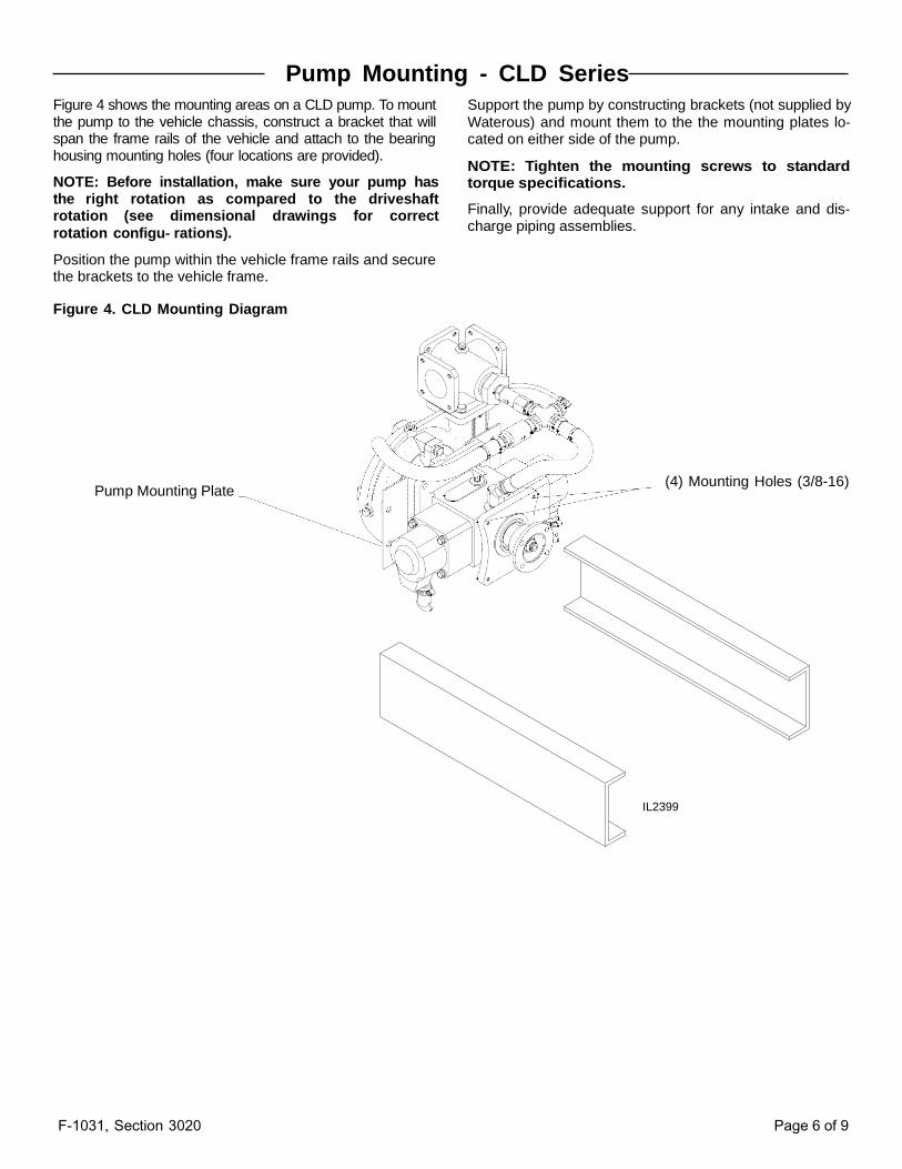
Pump Mounting - CLD Series
Figure 4 shows the mounting areas on a CLD pump. To mount the pump to the vehicle chassis, construct a bracket that will span the frame rails of the vehicle and attach to the bearing housing mounting holes (four locations are provided).
NOTE: Before installation, make sure your pump has the right rotation as compared to the driveshaft rotation (see dimensional drawings for correct
rotation configu‐ rations).
Position the pump within the vehicle frame rails and secure the brackets to the vehicle frame.
Support the pump by constructing brackets (not supplied by
Waterous) and mount them to the the mounting plates lo‐ cated on either side of the pump.
NOTE: Tighten the mounting screws to standard torque specifications.
Finally, provide adequate support for any intake and dis‐ charge piping assemblies.
Figure 4. CLD Mounting Diagram
Pump Mounting Plate (4) Mounting Holes (3/8-16)
IL2399
F-1031, Section 3020 Page 7 of 9
Pump Mounting - CLPA Series
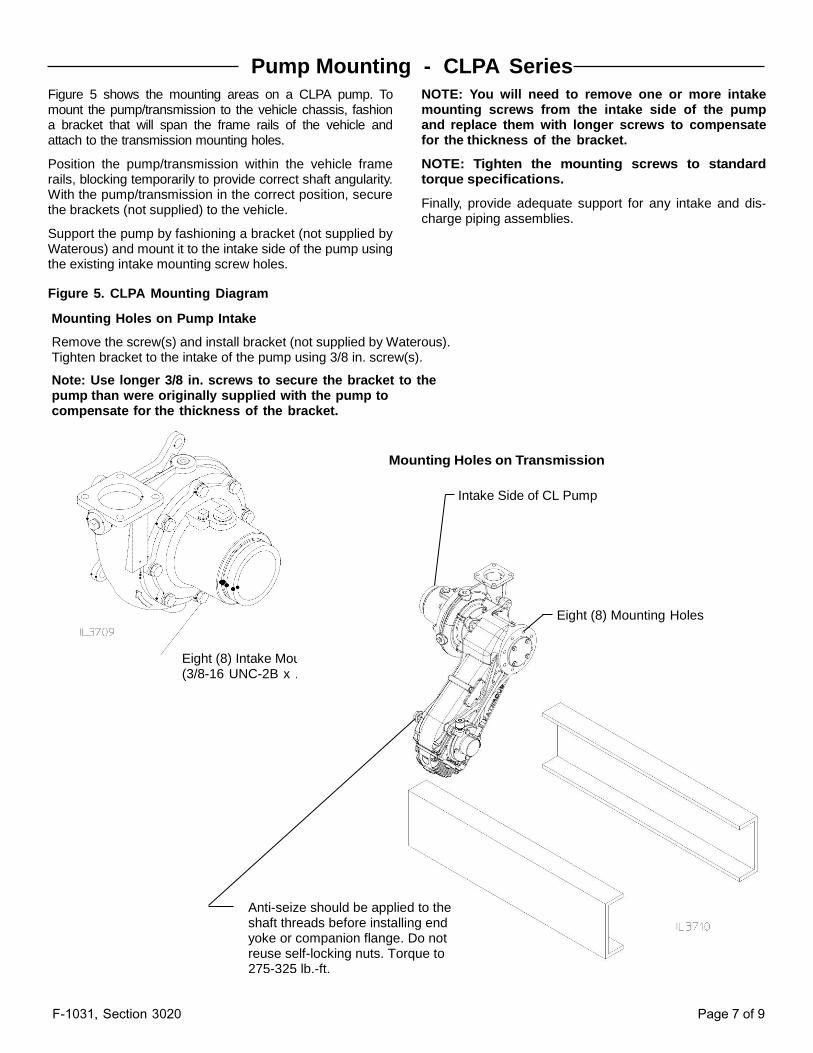
Figure 5 shows the mounting areas on a CLPA pump. To mount the pump/transmission to the vehicle chassis, fashion a bracket that will span the frame rails of the vehicle and attach to the transmission mounting holes.
Position the pump/transmission within the vehicle frame rails, blocking temporarily to provide correct shaft angularity. With the pump/transmission in the correct position, secure the brackets (not supplied) to the vehicle.
Support the pump by fashioning a bracket (not supplied by Waterous) and mount it to the intake side of the pump using the existing intake mounting screw holes.
NOTE: You will need to remove one or more intake mounting screws from the intake side of the pump and replace them with longer screws to compensate for the thickness of the bracket.
NOTE: Tighten the mounting screws to standard torque specifications.
Finally, provide adequate support for any intake and dis‐ charge piping assemblies.
Figure 5. CLPA Mounting Diagram
Mounting Holes on Pump Intake
Remove the screw(s) and install bracket (not supplied by Waterous). Tighten bracket to the intake of the pump using 3/8 in. screw(s).
Note: Use longer 3/8 in. screws to secure the bracket to the pump than were originally supplied with the pump to compensate for the thickness of the bracket.
Mounting Holes on Transmission
Intake Side of CL Pump
Eight (8) Intake Mounting Screws (3/8-16 UNC-2B x .500 Deep)
Anti-seize should be applied to the shaft threads before installing end yoke or companion flange. Do not reuse self-locking nuts. Torque to 275-325 lb.-ft.
Eight (8) Mounting Holes
F-1031, Section 3020 Page 8 of 9
Installation of Foam Manager If the fire pump is supplied with a Foam Manager™ (500 or 1000 GPM) the foam manifold and a FoamPro® foam proportioner are shipped loose from the factory. Refer to the FoamPro® Installation and Operation Manual (P/N L-0825) for controller wiring and foam concentrate inlet plumbing instructions.
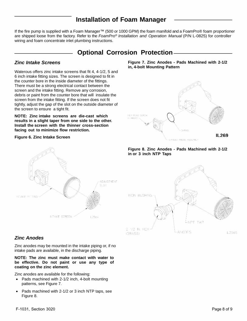
Zinc Intake Screens
Optional Corrosion Protection
Figure 7. Zinc Anodes - Pads Machined with 2-1/2 in, 4-bolt Mounting Pattern
Waterous offers zinc intake screens that fit 4, 4-1/2, 5 and 6 inch intake fitting sizes. The screen is designed to fit in the counter bore in the inside diameter of the fittings. There must be a strong electrical contact between the screen and the intake fitting. Remove any corrosion, debris or paint from the counter bore that will insulate the screen from the intake fitting. If the screen does not fit tightly, adjust the gap of the slot on the outside diameter of the screen to ensure a tight fit.
NOTE: Zinc intake screens are die-cast which results in a slight taper from one side to the other. Install the screen with the thinner cross-section facing out to minimize flow restriction.
Figure 6. Zinc Intake Screen
Figure 8. Zinc Anodes - Pads Machined with 2-1/2 in or 3 inch NTP Taps
Zinc Anodes
Zinc anodes may be mounted in the intake piping or, if no intake pads are available, in the discharge piping.
NOTE: The zinc must make contact with water to be effective. Do not paint or use any type of coating on the zinc element.
Zinc anodes are available for the following:
Pads machined with 2-1/2 inch, 4-bolt mounting patterns, see Figure 7.
Pads machined with 2-1/2 or 3 inch NTP taps, see Figure 8.
IL2695
F-1031, Section 3020 Page 9 of 9
Final Checks
After the pump, accessories, piping and miscellaneous connections are completely installed, check the points listed
be‐ low:
Lubrication
K & T Transmissions
Add any type of SAE 80W-90 gear oil through the fluid level hole or by removing the breather. Approximately 1 quart is required to fill the transmission when completely drained. The fluid should be level with bottom of the fluid level hole.
PA Transmissions
Add any type of automatic transmission fluid (ATF) through the fluid level hole or by removing the breather. Approximately 1 quart is required to fill the transmission when completely drained. The fluid should be level with bottom of the fluid level hole.
CLD Primers
Add any type of 10W-30 motor oil through the primer oil dip‐ stick. Approximately 1/2 quarts (.5 Liters) is required to fill the primers when completely drained.
Testing Perform the tests listed in F-1031, Section 1000,
“Centrifugal Fire Pump Principles of Operation,
Inspection Tests and Troubleshooting Guide.” During
the running tests, monitor the smoothness of operation,
listen for unusual noises and check for leaks.
CAUTION Be sure the propeller shafts used are of the slip- joint design. Frame deflection, temperature changes and similar factors may cause a propeller shaft without slip- joints to produce severe axial loads on the bearings and damage the pump.