classless inter domain routing - cidr ... classless inter domain routing - cidr marko luoma helsinki...
TRANSCRIPT

1
CLASSLESS INTER DOMAIN ROUTING - CIDR
Marko Luoma
Helsinki University of Technology
Laboratory of Telecommunications Technology
ABSTRACTAs the Internet evolved and become more familiar to people it become clear thatinternet would face several serious scaling problems. These included: exhaustion ofclass B addresses, routing information overflow and IP address space exhaustion.CIDR is a method to stem the tide of IP address allocation as well as routing tableoverflow. Basically, CIDR eliminates the concept of class A, B, and C networks andreplaces this with a generalized “IP prefix”.
TABLE OF CONTENTS
1. INTRODUCTION 2
1.1 EXHAUSTION OF CLASS B ADRESSES 21.2 ROUTING INFORMATION OVERLOAD 2
2. CLASSLESS INTER DOMAIN ROUTING 3
3. AGGREGATION 4
3.1 PROBLEM WITH MULTI -HOME ORGANISATIONS 4
4. ROUTE ADVERTISEMENT 5
4.1 RULES FOR ROUTE ADVERTISEMENT 54.2 EXAMPLE [4] 54.2.1 NETWORK NUMBERING 54.2.2 ROUTING ADVERTISEMENTS 6
5. INFORMATION EXCHANGE IN CIDR 7
5.1 INTRA-DOMAIN 75.2 INTER-DOMAIN 75.3 INTERNETWORKING WITH NON -CIDR NETWORKS 8

2
1. INTRODUCTIONAs the Internet evolved and become more familiar to people it become clear thatinternet would face several serious scaling problems. These included:
• Exhaustion of the class-B network address space. One fundamental cause of thisproblem was/is the lack of a network class of a size that is appropriate for a mid-sized organization. Class-C, with a maximum of 254 host addresses, is too small,while class-B, which allows up to 65534 addresses, is too large to be denselypopulated. The result is inefficient utilization of class-B network numbers.
• Routing information overload. The size and rate of growth of the routing tables inInternet routers was beyond the ability of software (and people) to effectivelymanage. Size of routing tables was directly proportional to number of networks.
• Eventual exhaustion of IP network numbers.
It become clear that the first two of these problems were likely to become critical inthe near term. Classless Inter-Domain Routing (CIDR) attempts to deal with theseproblems by defining a mechanism to slow the growth of routing tables and reduce theneed to allocate new IP network numbers. It does not attempt to solve the thirdproblem, which is of a more long-term nature, but instead endeavors to ease enough ofthe short to mid-term difficulties to allow the Internet to continue to functionefficiently while progress is made on a longerterm solution (Ipv6).
1.1 Exhaustion of class B adresses
The problem of class B exhaustion has occurred simply because the class B addressspace is too large for many middle-sized organizations and the class C address spaceis rarely enough to fulfil networking requirements.
By the time problems started only the half of the total number of 16384 class Baddresses are available. There is a total of about 2 million class C addresses and asmall number of them were already allocated by service providers. A class B networkwould consist of a maximum of 65536 hosts and a class C network consist with amaximum of only 256 hosts. The classification of internet networks is not practicablesince very few organizations have tens of thousands of hosts, but almost allorganizations have lots more hosts than 256. It has been estimated that a network sizeconsisting of about 4000 hosts is more suitable for organizations.
1.2 Routing information overload
The routing tables in the Internet have been growing as fast as the Internet and therouter technology specifically and computer technology in general has not been able tokeep pace. In December 1990 there were 2190 routes and 2 years later there were over8500 routes. In July 1995 there are were over 29,000 routes, which requireapproximately 10 MB in a router with a single peer. Routers at interconnection points(or multi-homed hosts doing full routing with many peers) receive these routes fromseveral peers, and need several dozen megabytes of RAM (and the appropriate CPUhorsepower) to handle this. Routers with 64MB of memory have the capacity forapproximately 60,000 routes after which some routes will just have to be left out of
3
the global routing tables, and the more likely ones to be left out are routes coveringsmall pieces of address space. [7]
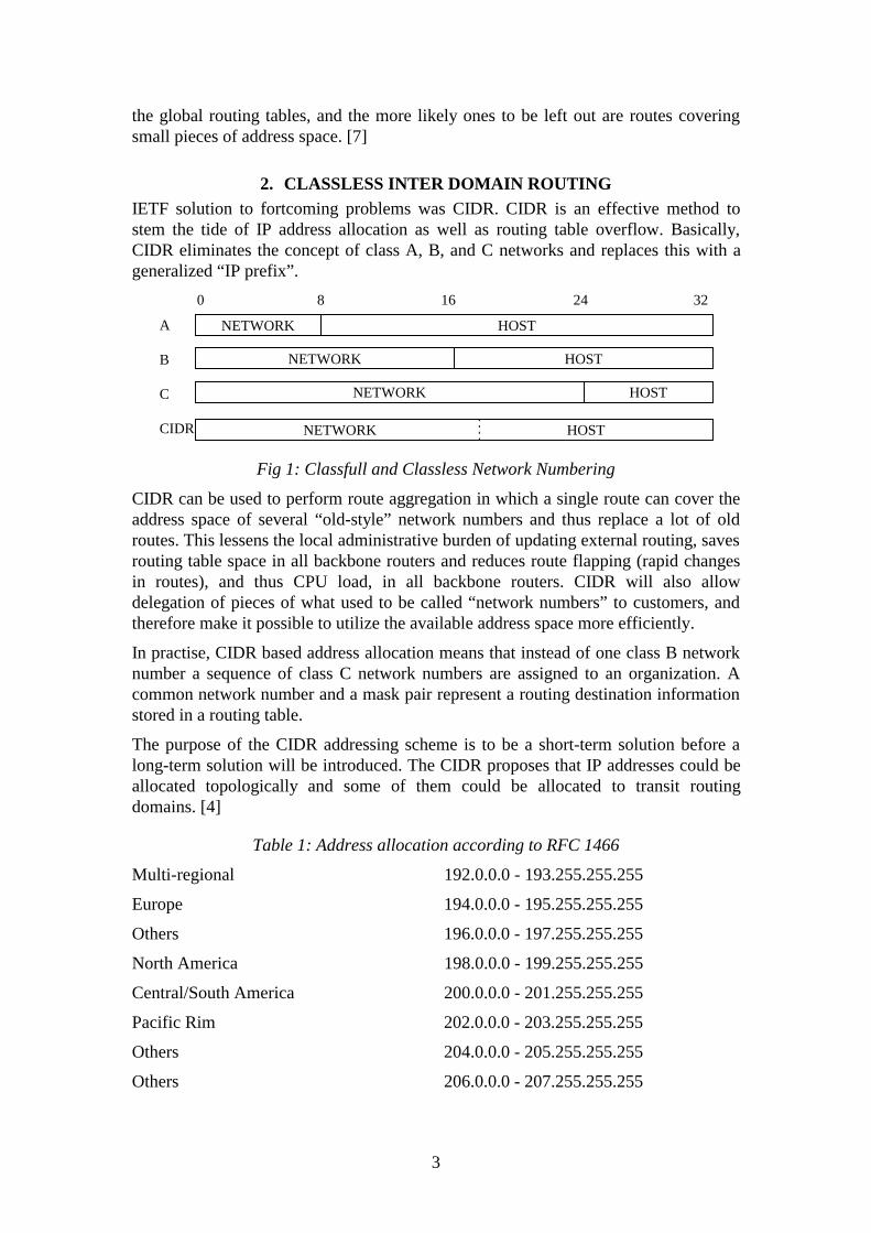
2. CLASSLESS INTER DOMAIN ROUTINGIETF solution to fortcoming problems was CIDR. CIDR is an effective method tostem the tide of IP address allocation as well as routing table overflow. Basically,CIDR eliminates the concept of class A, B, and C networks and replaces this with ageneralized “IP prefix”.
NETWORK
NETWORK
NETWORK
HOST
HOST
HOST
A
B
C
CIDR
0 8 16 24 32
NETWORK HOST
Fig 1: Classfull and Classless Network Numbering
CIDR can be used to perform route aggregation in which a single route can cover theaddress space of several “old-style” network numbers and thus replace a lot of oldroutes. This lessens the local administrative burden of updating external routing, savesrouting table space in all backbone routers and reduces route flapping (rapid changesin routes), and thus CPU load, in all backbone routers. CIDR will also allowdelegation of pieces of what used to be called “network numbers” to customers, andtherefore make it possible to utilize the available address space more efficiently.
In practise, CIDR based address allocation means that instead of one class B networknumber a sequence of class C network numbers are assigned to an organization. Acommon network number and a mask pair represent a routing destination informationstored in a routing table.
The purpose of the CIDR addressing scheme is to be a short-term solution before along-term solution will be introduced. The CIDR proposes that IP addresses could beallocated topologically and some of them could be allocated to transit routingdomains. [4]
Table 1: Address allocation according to RFC 1466
Multi-regional 192.0.0.0 - 193.255.255.255
Europe 194.0.0.0 - 195.255.255.255
Others 196.0.0.0 - 197.255.255.255
North America 198.0.0.0 - 199.255.255.255
Central/South America 200.0.0.0 - 201.255.255.255
Pacific Rim 202.0.0.0 - 203.255.255.255
Others 204.0.0.0 - 205.255.255.255
Others 206.0.0.0 - 207.255.255.255

4
Each block represents 131,072 addresses or approximately 6% of the total Class Caddress space.
3. AGGREGATIONThe routing table aggregation is based on classless addresses. It means that a block ofcontinuous network numbers have been assigned to a service provider. Anorganization gets a continuous sequence of network numbers from a service provider.A block of network numbers is represented as a single network number and a maskpair (IP prefix):
[xxx.xxx.xxx.xxx zzz.zzz.zzz.zzz]
Bitwise logical AND operation on the IP-address and IP-mask component of a tupleyields the sequence of leftmost contiguous significant bits that form the IP addressprefix. For example a tuple with the value [193.1.0.0 255.255.0.0] denotes an IPaddress prefix with 16 leftmost contiguous significant bits.
In aggregation a service provider advertises all the available addresses connected to ithierarchically at a lower level. The most straightforward case of this occurs whenthere is a set of routing domains that are all attached to a single service providerdomain (e.g. regional network), and which use that provider for all inter-domaintraffic. Each routing domain owns a prefix covering all connected subnetworks tothem. The service provider advertises, based on the routing domains' prefixes, one orseveral continuous prefixes to the upper hierarchical level to which it has connected.This allows a hierarchical and recursive abbreviation of routing information and datareduction while advertising routing information.
This infers a super-networking idea and a decision of super-networking could be donebased on topological or organizational information. The aggregation policy increasesthe hierarchy of network addressing since all sub-network level addresses must beknown at a certain upper level. Each upper level node knows the address space on thelower levels.
3.1 Problem with multi-home organisations
Aggregations are not simple to implement, for example in the case of multi-homedrouting domains. A multi-homed routing domain may consist of single-site campusesand companies that are attached to multiple backbones, large organizations that areattached to different providers at different locations in the same country, or multi-national organizations that are attached to backbones in a variety of countriesworldwide.
In generally multi-homed routing domains are organisations that might have manyservice providers to connect them to the outside world.
In the case of a multi-homed organization, each service provider should advertise thesame address space connected to them and the routing cost will not decrease.
In the case of changing the service provider, an organization should renumber thepreviously allocated address space to the new one given by the new service provider.Otherwise, traffic assigned to a client who has changed a service provider might go to

5
an old service provider. If a client wants to keep the same addresses, the aggregationof the old service provider must be changed.
4. ROUTE ADVERTISEMENT
4.1 Rules for Route Advertisement
Following rules are stated to be enough in order to achieve all benefits from CIDR. [4]
1. Routing to all destinations must be done on a longest-match basis only. Thisimplies that destinations which are multi-homed relative to a routing domainmust always be explicitly announced into that routing domain - they cannot besummarized (this makes intuitive sense - if a network is multi-homed, all of itspaths into a routing domain which is “higher” in the hierarchy of networksmust be known to the “higher” network).
2. A routing domain which performs summarization of multiple routes mustdiscard packets which match the summarization but do not match any of theexplicit routes which makes up the summarization. This is necessary to preventrouting loops in the presence of less-specific information (such as a defaultroute).
4.2 Example [4]
4.2.1 Network numbering
Block of 2048 class C network numbers beginning with 192.24.0.0 and ending with192.31.255.0 allocated to a single network provider, “A”. A “supernetted eq. CIDR”route to this block of network numbers would be described as 192.24.0.0 with mask of255.248.0.0.
This service provider connects six clients in the following order:
• “C1” requiring fewer than 2048 addresses (8 class C networks)
• “C2” requiring fewer than 4096 addresses (16 class C networks)
• “C3” requiring fewer than 1024 addresses (4 class C networks)
• “C4” requiring fewer than 1024 addresses (4 class C networks)
• “C5” requiring fewer than 512 addresses (2 class C networks)
• “C6” requiring fewer than 512 addresses (2 class C networks)
In all cases, the number of IP addresses “required” by each client is assumed to allowfor significant growth. The service provider allocates its address space as follows:
• C1: allocate 192.24.0 through 192.24.7. This block of networks is described by theroute 192.24.0.0 and mask 255.255.248.0
• C2: allocate 192.24.16 through 192.24.31. This block is described by the route192.24.16.0, mask 255.255.240.0
• C3: allocate 192.24.8 through 192.24.11. This block is described by the route192.24.8.0, mask 255.255.252.0
• C4: allocate 192.24.12 through 192.24.15. This block is described by the route192.24.12.0, mask 255.255.252.0

6
• C5: allocate 192.24.32 and 192.24.33. This block is described by the route192.24.32.0, mask 255.255.254.0
• C6: allocate 192.24.34 and 192.24.35. This block is described by the route192.24.34.0, mask 255.255.254.0
Note that if the network provider uses an IGP which can support classless networks,he can (but doesn't have to) perform “supernetting” at the point where he connects tohis clients and therefore only maintain six distinct routes for the 36 class C networknumbers. If not, explicit routes to all 36 class C networks will have to be carried bythe IGP. To make this example more realistic, assume that C4 and C5 are multi-homed through some other service provider, “B”. Further assume the existence of aclient “C7” which was originally connected to “B” but has moved to “A”. For thisreason, it has a block of network numbers which are allocated out “B”'s block of (thenext) 2048 class C network numbers:
• C7: allocate 192.32.0 through 192.32.15. This block is described by the route192.32.0, mask 255.255.240.0
For the multi-homed clients, we will assume that C4 is advertised as primary via “A”and secondary via “B”; C5 is primary via “B” and secondary via “A”. To connect thismess together, we will assume that “A” and “B” are connected via some common“backbone” provider “BB”.
4.2.2 Routing advertisements
To follow rule 1, “A” will need to advertise the block of addresses that it was givenand C7. Since C4 is multi-homed and primary through “A”, it must also beadvertised. C5 is multi-homed and primary through “B”. It need not be advertisedsince longest match will automatically select “B” as primary and the advertisement of“A's” aggregate will be used as a secondary.
Advertisements from “A” to “BB” will be:
• 192.24.12.0/255.255.252.0 primary (advertises C4)
• 192.32.0.0/255.255.240.0 primary (advertises C7)
• 192.24.0.0/255.248.0.0 primary (advertises remainder of A)
For “B”, the advertisements must also include C4 and C5 as well as it's block ofaddresses. Further, “B” may advertise that C7 is unreachable.
Advertisements from “B” to “BB” will be:
• 192.24.12.0/255.255.252.0 secondary (advertises C4)
• 192.24.32.0/255.255.254.0 primary (advertises C5)
• 192.32.0.0/255.248.0.0 primary (advertises remainder of B)

7
A B
C2192.24.16.0 - 192.24.31.0192.24.16.0/255.255.240.0
C3192.24.8.0 - 192.24.11.0192.24.8.0/255.255.252.0
C6192.24.34.0 - 192.24.35.0192.24.34.0/255.255.254.0
C1192.24.0.0 - 192.24.7.0
192.24.0.0/255.255.248.0
C4192.24.12.0 - 192.24.15.0192.24.12.0/255.255.252.0
C5192.24.32.0 - 192.24.33.0192.24.32.0/255.255.254.0
C7192.32.0.0 - 192.32.15.0192.32.0.0/255.255.240.0
BB
192.24.12.0/255.255.252.0 (C4)192.32.0.0/255.255.240.0 (C7)
192.24.0.0/255.248.0.0 (A)
192.24.12.0/255.255.252.0 (C4)192.24.32.0/255.255.254.0 (C5)
192.32.0.0/255.248.0.0 (B)
AS (A)
AS (B)
Fig 2: Route advertisement
If “A” loses connectivity to C7 (the client which is allocated out of “B's” space). In astateful protocol, “A” will announce to “BB” that 192.32.0.0/255.255.240.0 hasbecome unreachable. Now, when “BB” flushes this information out of its routingtable, any future traffic sent through it for this destination will be forwarded to “B”(where it will be dropped according to rule 2) by virtue of “B's” less specific match192.32.0.0/255.248.0.0. While this does not cause an operational problem (C7 isunreachable in any case), it does create some extra traffic across “BB”
5. INFORMATION EXCHANGE IN CIDR
5.1 Intra-domain
There are two ways to deal with interior (intra-domain) routing:
1. To use inter-domain protocols in intra-domain environment
2. To use routing protocols that support CIDR eq. OSPF, RIP II, Integrated IS-IS, and E-IGRP.
5.2 Inter-domain
The exterior (inter-domain) routing protocol that supports CIDR is BGP-4. Protocolslike RIP, BGP-3, EGP, and IGRP do not support CIDR [6].

8
The primary function of a BGP speaking system is to exchange network reachabilityinformation with other BGP systems. This network reachability information includesinformation on the list of Autonomous Systems (ASs) that reachability informationtraverses. This information is sufficient to construct a graph of AS connectivity fromwhich routing loops may be pruned and some policy decisions at the AS level may beenforced.
BGP-4 provides a new set of mechanisms for supporting classless inter-domainrouting. These mechanisms include support for advertising an IP prefix andeliminates the concept of network “class” within BGP. BGP-4 also introducesmechanisms which allows aggregation of routes, including aggregation of AS paths.[10]
BGP-4 enhances the AS-PATH attribute to include sets of autonomous systems aswell as lists. This extended format allows generated aggregate routes to carry pathinformation from the more specific routes used to generate the aggregate. [11]
5.3 Internetworking with non-CIDR networks
At each phase during the transition to CIDR one of the essential aspects of the Internetoperations will be the exchange of inter-domain routing information between CIDR-capable providers and CIDR-incapable provider.
When exchanging inter-domain routing information between a CIDR-capableprovider and a CIDR-incapable provider, it is of utmost importance to take intoaccount the view each side wants the other to present. This view has two distinctaspects:
• The type of routing information exchanged (i.e., Default route, traditional(non-CIDR) reachability information, CIDR reachability information)
• Routing information processing each side needs to do to maintain theseviews (e.g., ability to perform aggregation, ability to perform controlled de-aggregation)
The exchange of inter-domain routing information is expected to be controlled bybilateral agreements between the directly connected service providers. Consequently,the views each side wants of the other are expected to form an essential component ofsuch agreements. To facilitate troubleshooting and problem isolation, the bilateralagreements should be made accessible to other providers. [9]
REFERENCES/1/ Braun, Ford, Rekhter, CIDR and the Evolution of the Internet Protocol,
Proc. INET '93. 5p.
/2/ RFC 1466, E. Gerich, “Guidelines for Management of IP AddressSpace”, 26.5.1993. 10p.
/3/ RFC 1518, Y. Rekhter, T. Li, “An Architecture for IP Address Allocationwith CIDR”, 24.9.1993. 27p.

9
/4/ RFC 1519, V. Fuller, T. Li, J. Yu, K. Varadhan, “Classless Inter-DomainRouting (CIDR): an Address Assignment and Aggregation Strategy”,24.9.1993. 24p.
/5/ RFC 1517, R. Hinden, “Applicability Statement for the Implementation ofClassless Inter-Domain Routing (CIDR)”, 24.9.1993. 4p.
/6/ RFC 1817, Y. Rekhter, “CIDR and Classful Routing”, 4.8.1995. 2p.
/7/ CIDR FAQ v6, URL: http://www.ibm.net.il/~hank/cidr.html
/8/ Christian Huitema, Routing in the Internet, Prentice Hall, 1995.
/9/ RFC 1520, Y. Rekhter, C. Topolcic, “Exchanging Routing InformationAcross Provider Boundaries in the CIDR Environment”, 24.9.1993. 9p.
/10/ RFC 1771, Y. Rekhter, T. Li, “A Border Gateway Protocol 4 (BGP-4)”,21.3.1995
/11/ RFC 1774, P. Traina, “BGP-4 Protocol Analysis”, 21.3.1995 10p.