clean energy council install and supervise guidelines · pdf filecouncil install and supervise...
TRANSCRIPT

CLEAN ENERGY
COUNCIL INSTALL
AND SUPERVISE
GUIDELINES FOR
ACCREDITED
INSTALLERS
ISSUE 11, 1 MAY 2017

GRID-CONNECTED SOLAR PV SYSTEMS - INSTALL AND SUPERVISE GUIDELINES FOR ACCREDITED INSTALLERS
ISSUE 11, MAY 2017
2
1 GENERAL 5
2 DEFINITIONS 5
3 STANDARDS FOR INSTALLATION 5
4 LICENSING 6
4.1 Extra Low Voltage (ELV) 6
4.2 Low Voltage (LV) 6
5 DOCUMENTATION 7
6 RESPONSIBILITIES OF ACCREDITED PERSON 7
6.1 An accredited person shall sign-off on systems where they have; 7
6.2 Limits apply to the number of installations an accredited person shall sign-off per day 8
6.3 Multiple systems at one location 8
6.4 Grid Connect Battery Backup System 8
7 PV ARRAY INSTALLATION 9
7.1 General 9
7.2 Roof mounting (not building integrated) 9
7.3 Free standing PV arrays 11
7.4 Building integrated (BIPV) installations 11
7.5 Verification of AS1170.2 11
7.6 Attaching modules to array mounting structure 11
7.7 Earthing of array frames for a PV array with maximum voltage greater than ELV (including AC modules and micro inverter systems) 12
7.8 Wiring at the PV array 14
7.9 String protection 14
7.10 PV array DC isolator at array (Not applicable for micro inverter and AC modules systems) 14
TABLE OF CONTENTS
GRID-CONNECTED SOLAR PV SYSTEMS - INSTALL AND SUPERVISE GUIDELINES FOR ACCREDITED INSTALLERS
ISSUE 11, MAY 2017
3
7.11 PV array cable between array and inverter 18
8 INVERTER INSTALLATION 21
8.2 PV array DC isolator near inverter (Not applicable for micro inverter AC and modules systems) 22
8.3 AC isolator near inverter 23
8.4 AC Isolators for Micro inverter installation 24
8.5 AC cable selection 24
8.6 Solar supply main switch in switchboard 25
8.7 Shutdown procedure 27
8.8 Additional Requirements for Micro Inverters 27
8.9 Inverter Earth Fault Indication 27
9 METERING 28
10 SIGNAGE 28
11 COMMISSIONING 29
12 INSTALLATION AND COMMISSIONING 29
12.1 General 29
12.2 Insulation resistance measurement 29
12.3 String Inverter Installation and commissioning sample 30
12.4 Micro Inverter and AC Module Installation and commissioning sample 32
13 EXAMPLES OF SIGNAGE 34
13.1 String Inverter Systems 34
13.2 Micro Inverter Systems 35
13.3 Example of 1 X String, 1 X Inverter IES connected to sub board 36
13.4 Example of 1 X inverter, 2 X Arrays IES connected to main board 37
13.5 Example of 2 X String inverters IES connected to marshalling board 38
13.6 Example of Micro inverters connected to main board 39
14 ATTACHMENT 1: DANGEROUS SITUATION 40
15 ATTACHMENT 2: PV ARRAY ROOF MOUNTING 40

GRID-CONNECTED SOLAR PV SYSTEMS - INSTALL AND SUPERVISE GUIDELINES FOR ACCREDITED INSTALLERS
ISSUE 11, MAY 2017
4
These guidelines have been developed by Clean Energy Council. They represent latest industry best practice for the installation of grid-connected PV systems. © Copyright 2017 While all care has been taken to ensure these guidelines are free from omission and error, no responsibility can be taken for the use of this information in the installation of any grid-connected power system.
GRID-CONNECTED SOLAR PV SYSTEMS - INSTALL AND SUPERVISE GUIDELINES FOR ACCREDITED INSTALLERS
ISSUE 11, MAY 2017
5
______________________________________________________________________ 1 GENERAL
The objectives of these guidelines are to: • improve the safety, performance and reliability of solar photovoltaic power systems installed in the field • encourage Industry Best Practice for all design and installation work involving solar photovoltaic power
systems • provide a network of competent solar photovoltaic power systems designers and installers • increase the uptake of solar photovoltaic power systems , by giving customers increased confidence in the
design and installation work.
The performance of a reliable installation that fulfils customer expectations requires both careful design and correct installation practice. Compliance with relevant state health and safety regulations is also necessary. NOTE: These guidelines alone do not constitute a fully definitive set of rules and are to be read in conjunction with all relevant Australian standards. Where these guidelines have additional requirements above that stated in the Australian standards then these guidelines shall be followed. ______________________________________________________________________ 2 DEFINITIONS
This document uses the same terminology as outlined in AS/NZS 5033. Two important definitions are: 2.1.1 Where the word “shall” is used, this indicates that a statement is mandatory 2.1.2 Where the word “should” is used, this indicates that a statement is a recommendation
______________________________________________________________________ 3 STANDARDS FOR INSTALLATION
Accredited installers shall comply with the following standards where applicable: AS/NZS 3000 Wiring Rules
AS/NZS 5033 Installation and safety requirements for photovoltaic (PV) arrays
AS/NZS 4509.2 Stand-alone Power Systems – Design
AS/NZS 1170.2 Structural design actions – Wind Actions
AS 4777.1 Grid connection of energy systems via inverters – Installation requirements
AS/NZS 1768
Lightning Protection
AS/NZS 3008 Electrical installations – Selection of cables

GRID-CONNECTED SOLAR PV SYSTEMS - INSTALL AND SUPERVISE GUIDELINES FOR ACCREDITED INSTALLERS
ISSUE 11, MAY 2017
6
3.1.1 The grid-interactive inverter shall be tested in accordance with AS/NZS 4777.2 and with IEC 62109 (parts 1 and 2).
3.1.2 The grid-interactive inverter shall be listed on the Clean Energy Council’s approved inverter list (or approved by the Distribution Network Service Providers (DNSP)).
3.1.3 The system shall comply with the relevant electrical service and installation rules for the state where the system is installed. (NOTE: the local electricity distributor may have additional requirements.)
3.1.4 These guidelines set additional requirements to the standards. An accredited installer or supervisor is expected to follow these guidelines in addition to the requirements within the relevant standards.
3.1.5 These guidelines will become mandatory on 30 June 2017 ______________________________________________________________________ 4 LICENSING
4.1 Extra Low Voltage (ELV)
4.1.1 All extra low voltage wiring should be performed by a 'competent' person, which is defined by the Australian Standard AS/NZS 4509.1 stand-alone power systems as: "a person who has acquired through training, qualifications, experience or a combination of these, knowledge and skill enabling that person to correctly perform the task required."
4.2 Low Voltage (LV)
4.2.1 All low voltage work: >120V DC or >50V AC shall be performed by a licensed electrician. 4.2.2 A licensed electrician is required to be responsible for the safety of the system wiring prior to connection
of the system to the grid.
4.2.3 If the system contains ELV wiring installed by a non-licensed person, then a minimum level of inspection by the electrician prior to closing the PV array isolators would include:
An open circuit voltage test on each PV string and on the total array. A visual inspection of an open PV junction box (randomly selected) and the master array junction
box. These inspections/checks shall confirm: the array voltages are as designed and specified the appropriate cables (cross sectional area and insulation), junction fittings and enclosures have been used. An accredited non-electrician ELV installer is expected to carry out these checks.
GRID-CONNECTED SOLAR PV SYSTEMS - INSTALL AND SUPERVISE GUIDELINES FOR ACCREDITED INSTALLERS
ISSUE 11, MAY 2017
7
______________________________________________________________________ 5 DOCUMENTATION
All complex systems require a user manual for the customer. Grid-connected PV systems are no different. The following system installation documentation shall be provided (as specified in AS/NZS 5033). The documentation can be either supplied in hard copy or electronic form (at the customer’s discretion). Where the accredited installer is not also signing off as the CEC accredited designer for the installation, the accredited designer shall provide the information as indicated below.
5.1.1 A list of equipment supplied with model, description & serial numbers. – Obtained from CEC designer. Basic system information including system rating and component ratings, commissioning date
and equipment location. 5.1.2 A list of actions to be taken in the event of an earth fault alarm – including any remote monitoring
configuration. 5.1.3 The shutdown and isolation procedure for emergency and maintenance. 5.1.4 A basic connection diagram that includes the electrical ratings of the PV array, and the ratings of all
overcurrent devices and switches as installed – Obtained from CEC designer. 5.1.5 System performance estimate – Obtained from CEC designer. 5.1.6 Recommended maintenance for the system – Obtained from CEC designer. 5.1.7 Maintenance procedure and timetable – Obtained from CEC designer. 5.1.8 The commissioning sheet and installation checklist. 5.1.9 Array frame engineering certificate for wind and mechanical loading – Obtained from CEC designer. 5.1.10 Installer/designer’s declaration of compliance. 5.1.11 Warranty information – Obtained from CEC designer. 5.1.12 Equipment manufacturer’s documentation and handbooks for all equipment supplied – Obtained from
CEC designer. 5.1.13 Contact personnel for installation enquiries and system support 5.1.14 Voltage rise calculations or measurements 5.1.15 Details of any central protection, phase balancing or export control installed, including devices, wiring and
settings ______________________________________________________________________ 6 RESPONSIBILITIES OF ACCREDITED PERSON
6.1 An accredited person shall sign-off on systems where they have;
6.1.1 Undertaken the installation; or 6.1.2 Supervised the installation by others 6.1.3 Supervision includes visiting the site at:
Job set up Mid-installation check-up Testing and commissioning
6.1.4 Sign-off is defined as the installer or supervisor performing the testing and commissioning requirements stated in section 11.
6.1.5 The date of sign-off is the day that the installer or supervisor performs the testing and commissioning requirements.
Note: It is vitally important that a system is tested as per the commissioning requirements of this document to ensure it is safe at the time of final sign off.

GRID-CONNECTED SOLAR PV SYSTEMS - INSTALL AND SUPERVISE GUIDELINES FOR ACCREDITED INSTALLERS
ISSUE 11, MAY 2017
8
6.2 Limits apply to the number of installations an accredited person shall sign-off per day
6.2.1 Where an accredited person is installing or supervising complete installations only, they shall not sign off on more than three (3) installations per day.
6.2.2 Where an accredited person is installing or supervising complete installations and upgrades /repairs (the installation or replacement of panels only) in the same day, they shall not sign off more than two (2) complete installations and more than three (3) upgrades on the same day
6.2.3 Where an accredited person is installing or supervising complete installations and upgrades /repairs (the installation or replacement of panels only) in the same day, they shall not sign off more than one (1) complete installation and more than four (4) upgrades on the same day
6.2.4 Where an accredited person is installing or supervising upgrades and/or repairs to existing systems involving the installation or replacement of panels only, the installer or supervisor shall not sign off on more than five (5) system upgrades / repairs per day.
Note: The reasoning behind these requirements is to ensure integrity is maintained in the solar industry and that all systems are installed in a safe manner and meet all the guidelines and standards. Data from previous audit regimes identified that there was a direct correlation between systems deemed to require rectification (sub-standard installation) and the number of systems signed off in one day.
6.3 Multiple systems at one location
If a project involves multiple systems at one location, where the systems are installed in stages, the accredited person installing or supervising these installations may request a formal exemption from clause 6.2 to sign-off up to 10 systems per day. Example: multiple systems installed on an apartment block, or at a retirement village, where the cables roughed in on one date; the inverter, mounting frame and panels installed on another date; and the final connection and commissioning on an another date.
6.3.1 An installer shall contact the CEC and request an exemption from clause 6.2 prior to the installation starting. Exemptions to clause 6.2 WILL NOT be granted after a project has been completed.
6.3.2 The installer must provide details of the project and the installation schedule for assessment by the CEC. Exemptions may be granted by the CEC to installers who can demonstrate that the schedule of installation will ensure all systems are installed in a safe manner and meet all guidelines and standards.
6.3.3 Once the assessment is complete, the CEC will respond to the installer with a letter detailing the assessment finding, and exemption from clause 6.2.1 if granted. This letter shall be the only acceptable evidence of an exemption from clause 6.2.1 for the purposes of STC creation. Note: An administration fee may apply for all exemption request assessments in the future.
6.4 Grid Connect Battery Backup System
6.4.1 When installing a grid connect battery backup system the installation shall be performed by a person with CEC grid connected install accreditation with battery backup endorsement or a person(s) with CEC grid connected install accreditation and CEC stand-alone install accreditation
Note: The installation of battery storage has additional safety risks associated with their installation. These include: • Electric shock hazard • Energy hazard • Chemical hazard
GRID-CONNECTED SOLAR PV SYSTEMS - INSTALL AND SUPERVISE GUIDELINES FOR ACCREDITED INSTALLERS
ISSUE 11, MAY 2017
9
______________________________________________________________________ 7 PV ARRAY INSTALLATION
7.1 General
7.1.1 PV arrays for installation on domestic dwellings shall not have PV array maximum voltages greater than 600 V.
7.1.2 The following types of buildings are considered “domestic dwellings”, using the building classifications in the National Construction Code:
• Class 1 (e.g. a free-standing house, terrace house, town house, villa unit) • Class 2 (e.g. an apartment block.) • Class 3 (e.g. a hotel/motel, boarding house or guest house) • Class 10a (e.g. a private garage, carport, or shed)
7.1.3 Modules that are electrically in the same string shall all be installed at the same tilt angle and orientation
(unless using DC conditioning units). 7.1.4 Unless specified by the CEC system designer, the installer shall not install two parallel strings, connected
to the same MPPT input at the inverter, installed on different orientations (e.g. east and west). Note: Some manufacturers will not guarantee inverter performance where parallel strings are installed on different orientations. The system designer shall confirm that this arrangement is acceptable with the inverter manufacturer. A minimum tilt of 10° is recommended to take advantage of self-cleaning during rain events. Where modules are installed at a tilt angle less than 10°, the customer shall be advised about the need for more frequent cleaning of the modules, and this should be included in the recommended maintenance schedule.
7.2 Roof mounting (not building integrated)
7.2.1 All array supports, brackets, screws and other metal parts shall be of suitable low-corrosion materials suitable for the lifetime and duty of the system, that do not increase their rates of corrosion when mounted together in an array, and when mounted on the surface of the underlying structure. This may include techniques to minimise corrosion rates appropriate to the local environment, including but not restricted to methods such as: non-reactive separators between metal surfaces and under screw and bolt heads; and selection of materials with appropriate type and thickness of anti-corrosive coating.
7.2.2 Refer to the manufacturer’s guidelines to ensure that the materials introduced are compatible with the roofing.
7.2.3 Any roof penetrations shall be suitably sealed and waterproofed for the expected life of the system. (Refer to roofing manufacturer’s guidelines.). See section 7.11.6 for more details. If this is not possible then this shall be detailed in the system’s Maintenance Timetable.
7.2.4 It is important to allow sufficient clearance to facilitate self-cleaning of the roof to prevent the build-up of leaves and other debris (Refer to roofing manufacturers guidelines.)
7.2.5 If fauna (such as birds, vermin, etc) are a problem in the vicinity of the installation then consideration should be given to how to prevent them gaining access under the array.
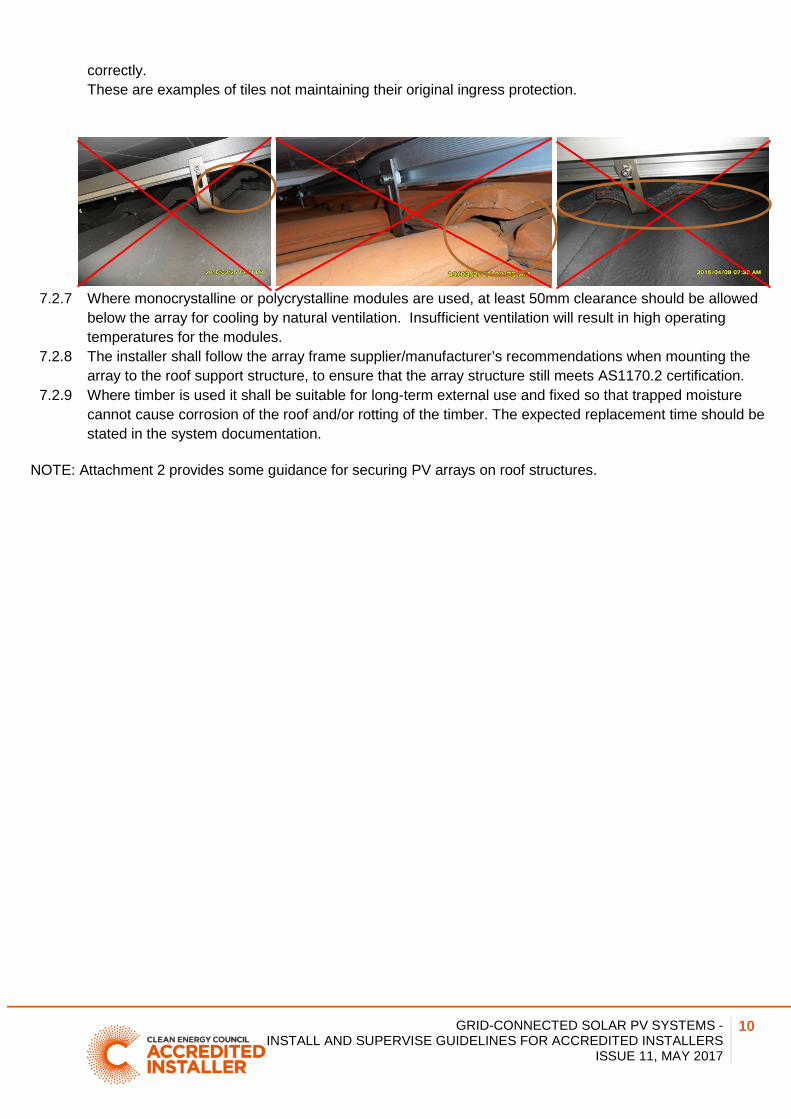
7.2.6 Tiles shall sit flat after the installation of tile mounting brackets to ensure the tiles maintain their original ingress protection. There may be a requirement to grind some of the underside of the tile to enable it to sit
GRID-CONNECTED SOLAR PV SYSTEMS - INSTALL AND SUPERVISE GUIDELINES FOR ACCREDITED INSTALLERS
ISSUE 11, MAY 2017
10
correctly. These are examples of tiles not maintaining their original ingress protection.
7.2.7 Where monocrystalline or polycrystalline modules are used, at least 50mm clearance should be allowed
below the array for cooling by natural ventilation. Insufficient ventilation will result in high operating temperatures for the modules.
7.2.8 The installer shall follow the array frame supplier/manufacturer’s recommendations when mounting the array to the roof support structure, to ensure that the array structure still meets AS1170.2 certification.
7.2.9 Where timber is used it shall be suitable for long-term external use and fixed so that trapped moisture cannot cause corrosion of the roof and/or rotting of the timber. The expected replacement time should be stated in the system documentation.
NOTE: Attachment 2 provides some guidance for securing PV arrays on roof structures.

GRID-CONNECTED SOLAR PV SYSTEMS - INSTALL AND SUPERVISE GUIDELINES FOR ACCREDITED INSTALLERS
ISSUE 11, MAY 2017
11
7.3 Free standing PV arrays
7.3.1 The array mounting frame shall be wind rated in accordance with AS 1170.2 part 2: Wind Loads. 7.3.2 Installation of footings, posts and/or in-ground fasteners shall follow the manufacturer’s instructions and
installation manual.
7.4 Building integrated (BIPV) installations
7.4.1 The installation of modules that are being used as building material e.g. tiles, building walls, sun-screens should only be installed by a person qualified to install that particular type of building element.
7.5 Verification of AS1170.2
7.5.1 Installers shall obtain from their frame supplier a copy of the engineering certificate stating that the array frame is certified to AS1170.2 for their location.
7.5.2 Installers shall obtain information on how the frame is to be mounted on the roof to maintain this certification.
7.5.3 The array frame shall be installed to the manufacturer’s instructions to ensure that the array structure meets AS1170.2 certification. The installer shall consider the following:
spacing between fixings for specific wind load regions area of roof that is applicable for panels to be installed (some manufacturers only allow the
frames to be installed in a specific internal zone of the roof) type, length and gauge of screws to be used. number of screws required per fixing size of batten/purlin required for fixing.
7.5.4 The installation checklist includes a clause stating that the system has been installed in accordance with the recommendations of the supplier/manufacturer. Copies of both these documents shall be included in the manual provided to the customer.
(NOTE: If installers are manufacturing their own frames, then they shall provide the certificates and include in the manual.)
7.6 Attaching modules to array mounting structure
7.6.1 Solar modules should be attached to the array structure either using the mounting holes provided by the manufacturer or via clamps.
7.6.2 Where modules are installed in such way that the junction box is to the side or at the bottom, care must be taken to ensure this is permitted by the manufacturer.
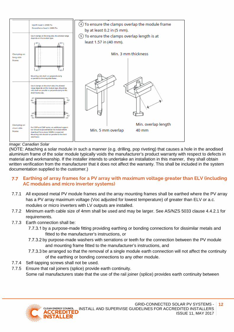
7.6.3 When using clamps solar panel manufacturer’s installation instructions shall be followed. The installer shall consider the following:
amount of overhang allowed from clamp to end of module size of clamp required.
GRID-CONNECTED SOLAR PV SYSTEMS - INSTALL AND SUPERVISE GUIDELINES FOR ACCREDITED INSTALLERS
ISSUE 11, MAY 2017
12
Image: Canadian Solar (NOTE: Attaching a solar module in such a manner (e.g. drilling, pop riveting) that causes a hole in the anodised aluminium frame of the solar module typically voids the manufacturer’s product warranty with respect to defects in material and workmanship. If the installer intends to undertake an installation in this manner, they shall obtain written verification from the manufacturer that it does not affect the warranty. This shall be included in the system documentation supplied to the customer.)
7.7 Earthing of array frames for a PV array with maximum voltage greater than ELV (including AC modules and micro inverter systems)
7.7.1 All exposed metal PV module frames and the array mounting frames shall be earthed where the PV array has a PV array maximum voltage (Voc adjusted for lowest temperature) of greater than ELV or a.c. modules or micro inverters with LV outputs are installed.
7.7.2 Minimum earth cable size of 4mm shall be used and may be larger. See AS/NZS 5033 clause 4.4.2.1 for requirements.
7.7.3 Earth connection shall be: by a purpose-made fitting providing earthing or bonding connections for dissimilar metals and
fitted to the manufacturer’s instructions, or by purpose-made washers with serrations or teeth for the connection between the PV module
and mounting frame fitted to the manufacturer’s instructions, and be arranged so that the removal of a single module earth connection will not affect the continuity
of the earthing or bonding connections to any other module. 7.7.4 Self-tapping screws shall not be used. 7.7.5 Ensure that rail joiners (splice) provide earth continuity.
Some rail manufacturers state that the use of the rail joiner (splice) provides earth continuity between

GRID-CONNECTED SOLAR PV SYSTEMS - INSTALL AND SUPERVISE GUIDELINES FOR ACCREDITED INSTALLERS
ISSUE 11, MAY 2017
13
rails. If the manufacturer does not provide this information, an earth strap shall be installed across the join.
7.7.6 As per AS/NZS 3000 the earth cable can be insulated unsheathed cable except when exposed to direct sunlight. If exposed to direct sunlight the insulated unsheathed cable shall have a physical barrier to prevent exposure to direct sunlight (e.g. conduit).
7.7.7 The earth cable shall be installed as per AS/NZS 3000 requirements. Particular attention shall be paid to mechanical protection and support. Earth cable cannot pass through a tile or steel roof without additional mechanical protection (conduit) and an appropriate collar flashing (e.g. dectite). The same conduit that is used for the PV array cable can also be used for the earth cable. These are examples of earth cable that is not adequately mechanically protected.
7.7.8 The earthing conductor from the PV array can connect to inverter’s main earth conductor in the A.C
output cable provided the following conditions are met: 7.7.9 Installation is not subject to lightning 7.7.10 Inverter A.C earth is of an appropriate size:
• Isolated inverter (transformer based) and floating array: inverter A.C earth size is appropriate • Non Isolated inverter (transformerless): earth conductor shall be sized according to AS/NZS
3000 using the size of the PV array cabling as the active conductor. • Functionally earthed arrays: see AS/NZS 5033 clause 4.4.2.2 for requirement.
Note: See AS/NZS 5033 clause 4.4.2.2 for more detailed information regarding this requirement
7.7.11 AC modules / Micro Inverters additional requirements (not subject to lightning) The earthing of the PV module and mounting frame can be achieved using the micro inverter earth connection (see AS/NZS 5033 clause 4.4.2.2).
GRID-CONNECTED SOLAR PV SYSTEMS - INSTALL AND SUPERVISE GUIDELINES FOR ACCREDITED INSTALLERS
ISSUE 11, MAY 2017
14
7.8 Wiring at the PV array
7.8.1 The electrical installation of the array shall be in accordance with AS/NZS 5033. 7.8.2 All LV wiring shall be undertaken by a licensed electrician. 7.8.3 Plastic cable ties are not to be used as the primary means of support. 7.8.4 The PV array wiring shall comply with the wiring requirements of AS/NZS 3000. 7.8.5 Cables shall be protected from mechanical damage. 7.8.6 The installer shall ensure that all connectors used are waterproof and connected securely to avoid the
possibility of a loose connection. 7.8.7 Only connectors which are the same type/model from the same manufacturer are allowed to be married at
a connection point. 7.8.8 Cables shall not lay on roofs or floors without an enclosure or conduit. 7.8.9 Cable size to be determined by AS/NZS 5033 Clause 4.3.6.1. 7.8.10 For LV PV arrays, the CEC recommend that under maximum load conditions, the voltage drop from the
most remote module in the array to the input of the inverter should not exceed 3% of the Vmp voltage (at STC).
7.8.11 In particular, refer to the clause in AS/NZS 3000 that refers to fauna which states: Where the presence of fauna is expected to constitute a hazard, either the wiring system shall be selected accordingly, or special protective measures shall be adopted.
7.8.12 All conduits exposed to direct sunlight shall be suitably UV rated.
7.9 String protection
Faults due to short circuits in modules, junction boxes, combiner boxes, module wiring or earth faults in array wiring can result in overcurrent within a PV array.
7.9.1 Overcurrent protection shall be provided where it is required by manufacturers of PV modules. The key criteria for this the module’s “Maximum Series Fuse Rating”, sometimes listed as “Maximum Reverse Current”.
7.9.2 AS/NZS 5033 Clause 3.3.4 defines the formula to calculate if string protection is required. Refer to Attachment 3 for more details of this method.
7.9.3 AS/NZS 5033 Clause 3.3.5.1 defines the rating of the fuse protection. 7.9.4 In LV arrays, overcurrent protective devices, where required, shall be placed in all current carrying
conductors not directly connected to earth. 7.9.5 In ELV arrays, overcurrent protective devices, where required for string and sub-array cables, shall be
placed in either the positive or negative conductor (the number of current carrying conductors minus one).
7.10 PV array DC isolator at array (Not applicable for micro inverter and AC modules systems)
The positive and negative terminal of a solar array or sub-array represents a hazard with potentially high risk when the output voltage is 120V DC or above. See Attachment 1 for more details.
Note the following requirements for the PV array isolator at array:
7.10.1 AS/NZS 5033:2014 Clause 4.4.1.5 makes it mandatory for an isolator to be installed within 3 meters of the array and visible from both locations for LV systems. This is to enable safe disconnection of the array and isolation of the PV array cable.
Isolators shall not be installed mid string E.g. Where one electrical string is split over different roof faces (all faces are at the same orientation) one isolator is required at the point where the PV panel wiring transitions from the PV array to the fixed wiring to the inverter at the array.
GRID-CONNECTED SOLAR PV SYSTEMS - INSTALL AND SUPERVISE GUIDELINES FOR ACCREDITED INSTALLERS
ISSUE 11, MAY 2017
15
7.10.2 Isolators shall not be fixed on any portion of the panel. 7.10.3 Isolators shall be fixed to the supports by the use of stainless steel screws (or by screws of galvanically
similar material) to minimise corrosion. 7.10.4 Isolators shall have an IP rating of at least IP 55, (Note: the CEC recommend using isolators rated to
IP66). 7.10.5 Isolators shall be UV resistant. 7.10.6 The recommended method of fixing isolators is by using fixing points that are on the outside of the
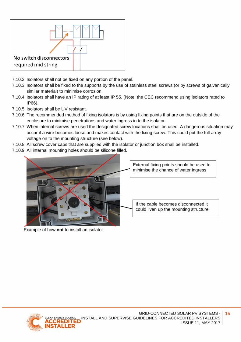
enclosure to minimise penetrations and water ingress in to the isolator. 7.10.7 When internal screws are used the designated screw locations shall be used. A dangerous situation may
occur if a wire becomes loose and makes contact with the fixing screw. This could put the full array voltage on to the mounting structure (see below).
7.10.8 All screw cover caps that are supplied with the isolator or junction box shall be installed. 7.10.9 All internal mounting holes should be silicone filled.
Example of how not to install an isolator.
If the cable becomes disconnected it could liven up the mounting structure
External fixing points should be used to minimise the chance of water ingress

GRID-CONNECTED SOLAR PV SYSTEMS - INSTALL AND SUPERVISE GUIDELINES FOR ACCREDITED INSTALLERS
ISSUE 11, MAY 2017
16
7.10.10 Isolators shall be readily available (this is defined as “Capable of being reached for inspection,
maintenance or repairs without necessitating the dismantling of structural parts, cupboards, benches or the like.”)
7.10.11 Isolators shall be rated for DC use. 7.10.12 Isolators shall be rated to interrupt full load and prospective fault currents (rated operational current
suitable for a temperature of 40°C ambient plus an additional 40°C, e.g. 80°C see below for example ).
Example of temperature de-rating curve (Image: NHP)
7.10.13 Isolators shall not be polarity sensitive. 7.10.14 Isolators shall interrupt all live conductors simultaneously. 7.10.15 Isolators shall not have exposed live parts in connected or disconnected state. 7.10.16 Shall comply with the requirements of IEC 60947 (series) and shall have a utilization category of at
least DC21B (refer IEC 60947-3). 7.10.17 Isolator voltage ratings shall be as per AS/NZS5033:2014 Appendix B:
for non-functionally earthed systems, isolated inverter (transformer based): voltage rating of both poles together of the switch-disconnector shall be at least the PV array maximum voltage (Voc Array adjust for lowest ambient temperature of site)
non-isolated inverter (transformerless based): voltage rating of each pole of the isolator/switch disconnector shall be at least the PV array maximum voltage. (Voc Array adjust for lowest ambient temperature of site)
7.10.18 Functionally earthed array presents specific issues. The voltage rating of isolators for these systems are detailed in AS/NZS 5033:2014 Appendix B.
7.10.19 Labelled “PV ARRAY D.C. ISOLATOR”. 7.10.20 Manufacturer’s installation instructions for isolators shall be followed regarding mounting orientation
to ensure the IP rating is maintained. The roof mounted isolator should be mounted such that the switch is in a sideways position.
(NOTE: Ensure that the switch does not shade the array.)
Entry points underneath or facing down the roof

GRID-CONNECTED SOLAR PV SYSTEMS - INSTALL AND SUPERVISE GUIDELINES FOR ACCREDITED INSTALLERS
ISSUE 11, MAY 2017
17
7.10.21 All entry points (conduit and cable glands) to the isolator should be on the lower end of the enclosure - either underneath or facing down the roof.
7.10.22 Where an entry to an isolator is a conduit gland the gland shall be rated IP 55 (CEC recommend IP 66) Note: If the conduit gland requires the conduit to be glued to maintain the IP rating the conduit shall be glued
Image: Cobalt Solar
7.10.23 Where the entry to an isolator is a cable gland the gland shall: Be rated at least IP 55 (CEC recommend IP 66). Where multiple cables go through one gland a multi hole cable gland shall be used.
7.10.24 There shall be no open ends of conduit. If a cable is required to exit from conduit, a cable gland (as
specified above) shall be installed on the end of the conduit to ensure the IP rating is maintained.
7.10.25 A secondary shield is required to shelter the DC isolator from direct exposure to rain and sun.
Where the panels are installed parallel to the roof, a shroud shall be installed over the isolator. PV DC Isolator(s) shall not be installed under a solar module when the panels are parallel to the roof.
Where the panels are on a tilt frame the isolator shall be installed in a location where it is sheltered by the panels. Note: Installation of a PV DC Isolator under a solar module, of a tilt array, may be considered as a “secondary shield.” However, this method must also comply with relevant local requirements (such as regulatory bodies, etc)

GRID-CONNECTED SOLAR PV SYSTEMS - INSTALL AND SUPERVISE GUIDELINES FOR ACCREDITED INSTALLERS
ISSUE 11, MAY 2017
18
7.10.26 If a junction box is used at the array it is recommended that junction boxes are mounted so that the
access to the junction box is made on the side of the junction box and not on a side facing up. Additionally the junction box should be installed in a location that is not exposed to the weather.
7.11 PV array cable between array and inverter
7.11.1 PV array cables within a domestic building that are installed in ceiling spaces, wall cavities, under floors shall be enclosed in metal or heavy-duty (HD) insulating conduit. When installed in a building, other than those listed previously, the PV array cable shall be in medium duty conduit as a minimum. Note: the intention of this is to provide additional protection for cables in locations where they may not be visible, e.g. a person drilling a hole into a wall cavity will hit the conduit first before making contact with the cables. Where cables are installed inside buildings but clearly visible (e.g. surface mounted conduit on the inside a of garage wall), medium-duty (MD) conduit is acceptable as an alternative.
Note: For non-domestic installations, see AS/NZS 5033 clause 4.3.6.3.2 for requirements.

GRID-CONNECTED SOLAR PV SYSTEMS - INSTALL AND SUPERVISE GUIDELINES FOR ACCREDITED INSTALLERS
ISSUE 11, MAY 2017
19
7.11.2 Conduits shall be installed so that they are adequately supported. These are examples of conduit that is not adequately supported.
7.11.3 AS/NZS5033:2014 does not allow for any medium duty (MD) conduit to be installed in the ceiling space.
Ensure that the transition from MD to HD occurs at the point of penetration of the roof. Alternatively, UV rated HD corrugated conduit could be used where the cable enters the ceiling space.
7.11.4 Double insulation of each conductor shall be maintained within wiring enclosures (e.g. conduit). 7.11.5 The wiring enclosure shall be labelled ‘SOLAR’ at not more than 2m intervals. 7.11.6 Where the PV array cable and conduit passes through a tile or steel roof an appropriate collar flashing
shall be installed (e.g. dectite).
Note: Grinding a tile and passing the conduit between tiles is not an acceptable method as it is in breach of AS/NZS 3000 (clause 3.9.4.3.1) Conduit passing through a hole in a steel roof and then sealed with silicon is in breach of Standards Australia Handbook 39-1997 (clause 8.6)

GRID-CONNECTED SOLAR PV SYSTEMS - INSTALL AND SUPERVISE GUIDELINES FOR ACCREDITED INSTALLERS
ISSUE 11, MAY 2017
20
Examples of non-acceptable methods.

GRID-CONNECTED SOLAR PV SYSTEMS - INSTALL AND SUPERVISE GUIDELINES FOR ACCREDITED INSTALLERS
ISSUE 11, MAY 2017
21
______________________________________________________________________ 8 INVERTER INSTALLATION
8.1.1 The inverter shall be installed in accordance with the manufacturer’s instructions. The installer shall do the following:
ensure the location is appropriate for the IP Rating of the inverter. Where this is not possible, then the inverter/s should be in an appropriate weatherproof enclosure. comply with specific environmental requirements e.g. not exposed to direct sunlight, direct rain, etc ensure mounting structure is able to support inverter weight ensure mounting structure material is appropriate for the inverter recommended clearances around the inverter shall be followed.
8.1.2 The inverter heat sink shall be clear of any obstacles to facilitate cooling of the inverter. 8.1.3 Cables connected to the inverter shall be mechanically secured in such a manner that they cannot be
inadvertently unplugged from the inverter. This can be achieved by: installing the inverter in an external enclosure (with cables suitably supported) the use of an inverter which has the cable connection area of inverter covered by a removable enclosure/cover which protects the supported cables so that there are no exposed, unsupported cable loops the use of conduit and secure wall fixings. Note: Where the inverter requires DC connectors to be used, a maximum allowable distance of no more than 300mm of unprotected DC cable shall be permitted between connectors and conduit, provided the location is not subject to mechanical damage. Where the inverter is exposed to the weather there shall be no open ends of conduit. If a cable is required to exit from a conduit, an appropriate cable gland shall be installed on the end of the conduit to ensure the IP rating is maintained (see section 7.10.24.
8.1.4 The installer shall ensure that the inverter is configured for Australia, and that the AS/NZS4777.2 parameters are loaded. Note: one method to ensure the 4777.2 parameters are installed is by monitoring the inverter power out when the inverter is turned on. The inverter should not go straight to full power. It is required to ramp up from 0%-100% over a 6 minute period.
8.1.5 The installer shall ensure that the grid parameters of the inverter are set to the local distributor’s requirements.
GRID-CONNECTED SOLAR PV SYSTEMS - INSTALL AND SUPERVISE GUIDELINES FOR ACCREDITED INSTALLERS
ISSUE 11, MAY 2017
22
8.2 PV array DC isolator near inverter (Not applicable for micro inverter AC and modules systems)
8.2.1 Where the inverter in LV systems is not in sight of the array or more than 3m from the array, PV array switch-disconnector/s shall also be installed adjacent to the inverter. Note: Generally the PV array DC isolator at the inverter will always be required for roof top mounted systems.
8.2.2 All PV array switch-disconnectors shall be readily available (see section 7.10.10 for details on readily available).
8.2.3 For inverters with an integrated switch-disconnector: a separate switch-disconnector is not required at the inverter if the switch-disconnector is mechanically interlocked with a replaceable module of the inverter and allows the module to be removed from the section containing the switch-disconnector without risk of electrical hazards.
8.2.4 Where multiple disconnection devices are required to isolate power conversion equipment, they shall be grouped so that they all operate simultaneously, or they shall all be grouped in a common location and have warning signs indicating the need to isolate multiple supplies to isolate the equipment (see section 12 for examples of signs).
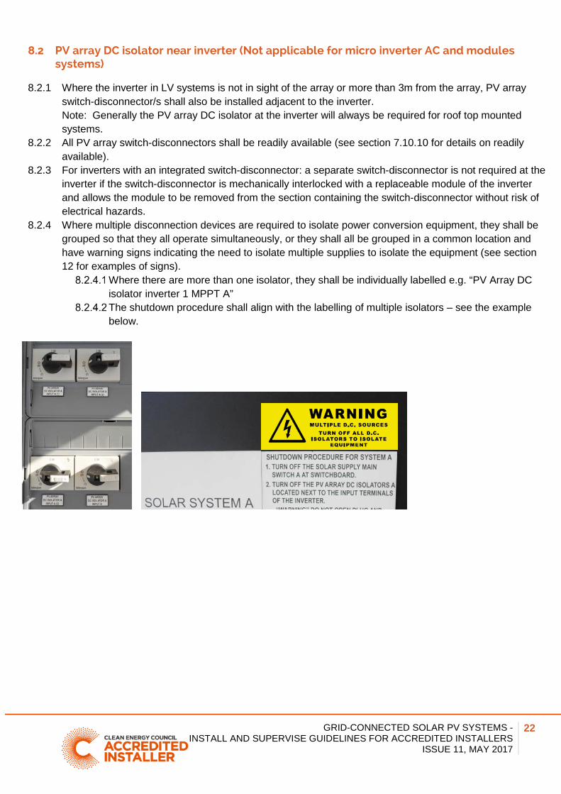
Where there are more than one isolator, they shall be individually labelled e.g. “PV Array DC isolator inverter 1 MPPT A” The shutdown procedure shall align with the labelling of multiple isolators – see the example below.

GRID-CONNECTED SOLAR PV SYSTEMS - INSTALL AND SUPERVISE GUIDELINES FOR ACCREDITED INSTALLERS
ISSUE 11, MAY 2017
23
8.2.5 Where strings are paralleled at the inverter, the CEC recommend that this should occur on the inverter side of the disconnection devices, or in the inverter itself.
Note: This will enable the cable to either string to be safely de-energised, without the need to turn off both rooftop isolators.
8.2.6 Where the inverter and isolator are exposed to the weather the isolator shall have an IP rating of at least IP 55, (Note: the CEC recommend using isolators rated to IP66).
8.2.7 Where an isolator is exposed to the weather, the CEC recommend that there be no top entries into the isolator, and drip loops are utilised at the bottom of the isolator to minimise water ingress.
8.2.8 PV array isolators shall meet the requirements of 7.10.6 to 7.10.23.
8.3 AC isolator near inverter
The purpose of the AC isolator is to de-energise the inverter for maintenance or fault rectification.
Conduit entry at bottom of isolator – drip loop

GRID-CONNECTED SOLAR PV SYSTEMS - INSTALL AND SUPERVISE GUIDELINES FOR ACCREDITED INSTALLERS
ISSUE 11, MAY 2017
24
8.3.1 Where the inverter is not adjacent to the switchboard to which it is connected, an isolator shall be provided at the inverter so that a person operating the switch has a clear view of any person working on the inverter - refer to AS/NZS 3000 7.3.4.
8.3.2 Connection of a.c. and d.c. components in the same enclosure shall not be mounted on a common conductive mounting rail.
8.3.3 A.c. and d.c. circuits within enclosures shall be physically segregated by an insulation barrier (see AS/NZS 5033:2014 clause 4.4.4.3). Note: this is to reduce the chance of a.c. and d.c. cables coming in to contact with each other.
8.3.4 Where the inverter and isolator are exposed to the weather the isolator shall have an IP rating of at least IP 55, (Note: the CEC recommend using isolators rated to IP66).
8.3.5 Where an isolator is exposed to the weather, , the CEC recommend that there be no top entries into the isolator and drip loops should be utilised at the bottom of the isolator to minimise water ingress.
8.4 AC Isolators for Micro inverter installation
8.4.1 A labelled, lockable, isolating switch (inverter a.c. isolator) shall be installed at the point of transition from micro inverter interconnect cable to fixed wiring. The purpose of the a.c. isolator is to de-energise the a.c. from the micro inverter for maintenance or fault rectification
8.4.2 The isolator shall be installed adjacent to the inverter or inverter group. This isolator may be a single isolator and can be used to isolate multiple adjacent inverters.
8.4.3 Where micro inverters are not installed adjacent to each other, additional isolators shall be installed. 8.4.4 Isolator enclosures shall be IP55 rated (CEC recommend IP66) 8.4.5 All entry points (conduit and cable glands) to the isolator should be on the lower end of the enclosure -
either underneath or facing down the roof. 8.4.6 A secondary shield is recommended to shelter the Inverter AC isolator from direct exposure to rain and
sun.
8.5 AC cable selection
AC cables shall comply with the wiring requirements of AS/NZS 3000. 8.5.1 The overall voltage rise from the point of supply and the inverter AC terminals shall not exceed 2% of
the nominal voltage at the point of supply. Individual states and territories may have their own specific
Conduit entry at bottom of isolator – drip loop

GRID-CONNECTED SOLAR PV SYSTEMS - INSTALL AND SUPERVISE GUIDELINES FOR ACCREDITED INSTALLERS
ISSUE 11, MAY 2017
25
requirements regarding cable selection and voltage rise. The installer shall ensure these are also complied with.
It is recommended that the voltage drop between the inverter and the main switchboard should be kept as small as possible (recommended <1%) to minimise voltage rise within the installation See table below).
Note: This will limit inverter disconnection in areas where the grid voltage may be high, to decrease incidents of overvoltage trips for inverters. This is also an issue for micro inverter installations where the AC cable run may be long
TABLE 1 MAXIMUM CABLE LENGTHS FOR 1% VOLTAGE RISE
Inverter Configuration Single Phase
Three Phase Three Phase
Inverter Rating (kVA) 5 5 10 Conductor Current (A) 21.7 7.2 14.5 Cable Conductor Size (mm2) Conductor
Material Maximum Route length (m)
Maximum Route length (m)
Maximum Route length (m)
6 Cu 14 85 42 10 Cu 24 143 71 16 Cu 38 227 113 25 Cu 59 357 179
8.5.2 The inverter shall be connected by fixed wiring to a dedicated circuit on a switchboard. 8.5.3 AC cables between the inverter and any switchboard and all the cables between any distribution boards
and a main switchboard which carry current from the inverter shall be rated for at least the full output current of the inverter energy system.
8.5.4 All cabling shall be sized in accordance with AS/NZS 3000 and AS/NZS 3008.
8.6 Solar supply main switch in switchboard
8.6.1 The inverter should be connected directly to the main switchboard. 8.6.2 Where this is not possible or not desirable, the inverter energy system should be connected to the
distribution board located physically nearest to the inverter, and the main switchboard. All intermediate distribution boards shall be appropriately labelled (see section 13 for examples of signs)
8.6.3 Labelled “Main Switch (Grid Supply)” 8.6.4 The main switch for the switchboard, to which the inverter is connected, shall be a lockable switch. 8.6.5 An RCD dedicated for an IES may be used to meet the mechanical protection cable protection
requirements and isolation requirements of AS/NZS 3000 for the cable between the switchboard and the IES. If an RCD is used, it shall disconnect actives & neutral and be the type specified by the manufacturer.
NOTE: An RCD shall not be connected between the switchboard and a multimode inverter.

GRID-CONNECTED SOLAR PV SYSTEMS - INSTALL AND SUPERVISE GUIDELINES FOR ACCREDITED INSTALLERS
ISSUE 11, MAY 2017
26
8.6.6 In accordance with AS/NZS 3000, the cable between the switchboard and inverter requires protection so it is recommended that the isolator is a suitably rated circuit breaker.
8.6.7 Arrangements of Multiple Main Switches at a Main Switchboard or Distribution Switchboard shall comply with table 2 below:
When three phase inverters are connected to a three phase supply connection, a single three-pole main switch shall be installed IES 5kVA or below, main switches shall be grouped
8.6.8 For inverter Energy Systems (IES) on different switchboards, refer to AS/NZS 4777.1 clause 5.5.4
Please refer to the table 2 below TABLE 2
ARRANGEMENTS OF MAIN SWITCHES
Maximum rating of IES
Single-phase supply
connection
Two-phase supply connection
Three-phase supply connection
Three-phase supply connection
Type of inverter Single-phase Single or two-phase Single-phase Three-phase
IES ≤5 kVA Grouped Grouped Where number of IES is >2, a two-pole main switch shall be installed. Inverter outputs should be balanced across phases
Grouped Where number of IES is >2, a three-pole main switch should be installed. Inverter outputs should be balanced across phases
Single three-pole main switch
5 < IES ≤30 kVA Not permitted Two-pole main switches shall be installed. Where number of main switches required >2 on a switchboard, then a single Main Switch (Inverter Supply) with its own distribution switchboard
Three-phase main switches should be installed. Where number of main switches required >2 on a switchboard, then a single Main Switch (Inverter Supply) with its own distribution switchboard should be used
Single three-pole main switch
30 < IES ≤200 kVA Not permitted Not permitted Where inverters are co-located use distribution and single Submain Switches (Inverter Supply). Where inverters are not co-located, minimize the number of isolation points for safe isolation
Single three-pole main switch
NOTE: All single-phase inverters connected to three-phase supply are to be balanced across phases and isolated in groups of three by operation of three-pole isolators.

GRID-CONNECTED SOLAR PV SYSTEMS - INSTALL AND SUPERVISE GUIDELINES FOR ACCREDITED INSTALLERS
ISSUE 11, MAY 2017
27
8.7 Shutdown procedure
A shutdown procedure is required to ensure safe de-energisation of the system. 8.7.1 The shutdown procedure shall reflect the specific requirements of the individual system. All isolating
switches referred to in the shutdown procedure shall correspond to individual isolator labels. E.g “PV array DC isolator”, “Solar Supply Main Switch”
8.7.2 For central inverter systems, an engraved label showing the shutdown procedure shall be installed adjacent to the inverter. An example shutdown procedure would be as follows:
• Turn off the main switch solar supply at the AC switchboard and then the AC isolator at the inverter (where installed) then
• Turn off the PV array isolator at the inverter.
WARNING: PV array DC isolators do not de-energise the PV array and array cabling. (see below for example)
8.7.3 Micro inverter and AC module systems (shall be installed at the switchboard to which the inverter is
connected) An example shutdown procedure would be: • Turn off the main switch solar supply at the AC switchboard
This will isolate the PV array
8.7.4 DC Conditioning Units The shutdown procedure must reflect the specific requirements of the individual system. Note: As this is different for the various technologies an example cannot be given
8.8 Additional Requirements for Micro Inverters
The following is in addition to the above requirements for all inverters. 8.8.1 Each input of the micro inverter is limited to 350W PV power at STC and at ELV. 8.8.2 DC cable length is less than 1.5m (including any adaptor cables) 8.8.3 The method of cable support for the interconnecting AC cable and DC panel cables shall have a life as
long as the system. 8.8.4 Cable support shall ensure that there is no stress placed on connectors. 8.8.5 Plugs, sockets and connectors shall only be mated with those of the same type from the same
manufacturer 8.8.6 A PV array disconnection device is not required for PV modules connected to micro inverters (AS/NZS
5033:2014 clause 4.4.1.2) Note: See section 7 for array earthing requirements for micro inverter systems.
8.9 Inverter Earth Fault Indication
As of 11 July 2015 AS/NZS 5033 requires the installation of an earth fault alarm indication

GRID-CONNECTED SOLAR PV SYSTEMS - INSTALL AND SUPERVISE GUIDELINES FOR ACCREDITED INSTALLERS
ISSUE 11, MAY 2017
28
8.9.1 Where the PV array maximum voltage is greater than ELV an earth fault system shall be installed. 8.9.2 The alarm system may be an audible signal, indicator light or another form of fault communication, e.g.
fax, email, SMS. The fault indication shall be installed in a way that it will make the system owner aware of the fault and initiate an action to correct an earth fault.
8.9.3 Micro inverter and a.c. module systems operate at with a PV array maximum voltage in the ELV range and therefore are not required to have the earth fault indication, although the CEC recommends that if the system has the capability it should be installed.
8.9.4 Where the system utilises remote monitoring to inform the customer of an earth fault the configuration of the remote monitoring shall be provided in the customer manual (see section 5).
______________________________________________________________________ 9 METERING
9.1.1 The installer shall notify the customer of the metering processes. 9.1.2 The system shall not be energized until correct metering is installed, other than for testing or
commissioning purposes as defined in section 12. Note: AS/NZS3000 clause 7.3.3 states that the system may not be energised until a formal agreement has been made with the electricity distributor.
______________________________________________________________________ 10 SIGNAGE
10.1.1 All signage on switches, isolators and within distribution boards and switchboards shall be in accordance with AS 4777 and AS/NZS 5033 and/or:
10.1.2 The relevant electrical service and installation rules for the state where the system is installed. 10.1.3 Where multiple systems are installed at one premises, labelling shall accurately reflect which devices
control which equipment.
10.1.4 See section 13 for examples of signs.

GRID-CONNECTED SOLAR PV SYSTEMS - INSTALL AND SUPERVISE GUIDELINES FOR ACCREDITED INSTALLERS
ISSUE 11, MAY 2017
29
______________________________________________________________________ 11 COMMISSIONING
11.1.1 The commissioning sheets provided with these guidelines (or similar document) shall be completed by the accredited installer or the accredited supervisor (with suitably licensed person).
11.1.2 A fully completed copy shall be provided to the customer in the system documentation and a copy shall be retained by the accredited person.
Note: It is vitally important that a system is tested as per the commissioning requirements of this document to ensure it is safe at the time of final sign off. Additionally, it enables the installer to prove the system was correctly installed at the time of installation should any questions arise post installation. ______________________________________________________________________ 12 INSTALLATION AND COMMISSIONING
12.1 General
WARNING: Where short circuit current measurements are required, follow AS/NZS 5033 Appendix D for the steps that shall be undertaken to measure the short circuit current safely. NOTE: Some projects require that short circuit currents are recorded as part of the contractual commissioning; otherwise a record of the actual operating current of each string is sufficient. This could be done by using the meter on the inverter or by using a clamp meter when the system is operational.
12.2 Insulation resistance measurement
WARNING: PV array dc circuits are live during daylight and, unlike a conventional ac circuit, cannot be isolated before performing this test. Follow AS/NZS 5033 Appendix D4 for the steps that shall be undertaken to measure the insulation resistance safely.

GRID-CONNECTED SOLAR PV SYSTEMS - INSTALL AND SUPERVISE GUIDELINES FOR ACCREDITED INSTALLERS
ISSUE 11, MAY 2017
30
12.3 String Inverter Installation and commissioning sample
INSTALLATION DETAILS Address of installation:
PV module manufacturer and model number:
Number of modules in series in a string:
Number of strings in parallel in PV array:
Inverter manufacturer and model number:
Number of inverters: Number of MPPTs: PV ARRAY PV array tilt ……………………° PV array orientation ……………………° Array frame is certified to AS1170.2 for installation location
Array frame is installed to manufacturer’s instructions
No galvanically dissimilar metals are in contact with the array frames or supports
Roof penetrations are suitably sealed and weatherproofed
PV wiring losses are less than 3%at the maximum current output of the array
Where PV array comprises multiple strings- string protection has been provided
Wiring is protected from mechanical damage and is appropriately supported
Weatherproof PV array isolator mounted adjacent to the array (Brand / Model:…………………………..Rating:………………. ………………….Vdc,…………….Adc)
LV DC and AC INSTALLATION All low voltage wiring has been installed by a licensed electrical tradesperson
All wiring has been tested and approved by qualified electrical tradesperson

GRID-CONNECTED SOLAR PV SYSTEMS - INSTALL AND SUPERVISE GUIDELINES FOR ACCREDITED INSTALLERS
ISSUE 11, MAY 2017
31
INVERTER PV array isolator mounted adjacent to the inverter (Brand / Model:…………………………..Rating:………………. ………………….Vdc,…………….Adc)
Isolator is mounted on output of the inverter (where required)
Lockable AC circuit breaker mounted within the switchboard to act as the inverter main switch for the PV/inverter system (Rating ……….. A )
Inverter is installed as per manufacturer’s specification
Inverter ceases supplying power within two seconds of a loss of AC mains
Inverter does not resume supplying power until mains have been present for more than 60 seconds. The inverter shall not go straight to full power. It is required to ramp up from 0%-100% over a 6 minute period.
CONTINUITY CHECK Circuit checked (record a description of the circuit checked in this column) Continuity of all string, sub-array and array cables
Continuity of all earth connections (including module frame)
SYSTEM CHECK WARNING:
• IF A STRING IS REVERSED AND CONNECTED TO OTHERS, FIRE MAY RESULT. • IF POLARITY IS REVERSED AT THE INVERTER DAMAGE MAY OCCUR TO THE INVERTER.
Polarity Voltage Short Circuit Operating Current
String 1 V A A String 2 V A A String 3 V A A String 4 V A A Sub-arrays where required V A A PV array at PV array switch-disconnector V A A Irradiance at time of recording the current W/m2 W/m2 INSULATION RESISTANCE MEASUREMENTS (see table 12.3.1 for minimum values of insulation resistance) Array positive to earth MΩ
Array negative to earth MΩ
INSTALLER INFORMATION CEC Accredited installer’s name:
CEC Accreditation number:
I verify that the above system has been installed to all relevant standards
Signed: Date:
CEC Accredited Designer’s name:
Licensed electrician’s name: (where applicable, e.g. LV work)
Electrician’s licence number:
Signed: Date:

GRID-CONNECTED SOLAR PV SYSTEMS - INSTALL AND SUPERVISE GUIDELINES FOR ACCREDITED INSTALLERS
ISSUE 11, MAY 2017
32
Table 12.3.1 Minimum insulation resistance
12.4 Micro Inverter and AC Module Installation and commissioning sample
INSTALLATION DETAILS Address of installation:
PV module manufacturer and model number:
Number of modules in array:
Inverter manufacturer and model number:
Number of inverters:
PV ARRAY PV array 1 tilt……………………° PV array 1 orientation..…° Number of panels…… PV array 2 tilt……………………° PV array 2 orientation..…° Number of panels…… PV array 3 tilt……………………° PV array 3 orientation..…° Number of panels…… PV array 4 tilt……………………° PV array 4 orientation..…° Number of panels…… Array frame is certified to AS1170.2 for installation location
Array frame is installed to manufacturer’s instructions
Wiring is protected from mechanical damage and is appropriately supported
No galvanically dissimilar metals are in contact with the array frames or supports
Roof penetrations are suitably sealed and weatherproofed
LV DC and AC INSTALLATION All low voltage wiring has been installed by a licensed electrical tradesperson
All wiring has been tested and approved by qualified electrical tradesperson

GRID-CONNECTED SOLAR PV SYSTEMS - INSTALL AND SUPERVISE GUIDELINES FOR ACCREDITED INSTALLERS
ISSUE 11, MAY 2017
33
INVERTER AC isolator mounted adjacent to each group of micro inverters (Rating:………………..Vdc, …………….Adc)
Inverter communications device has been installed inverter (where required)
Lockable AC circuit breaker mounted within the switchboard to act as the inverter main switch for the PV/inverter system (Rating ……….. A )
Inverter is installed as per manufacturer’s specification
Inverter ceases supplying power within two seconds of a loss of AC mains
Inverter does not resume supplying power until mains have been present for more than 60 seconds.
CONTINUITY CHECK Circuit checked (record a description of the circuit checked in this column)
SYSTEM CHECK (may need to be verified through the system communications portal) WARNING:
• IF POLARITY IS REVERSED AT THE INVERTER DAMAGE MAY OCCUR TO THE INVERTER.
Polarity Operating Voltage
Operating Current
Polarity Operating Voltage
Operating Current
Panel 1 V A Panel 11 V A Panel 2 V A Panel 12 V A Panel 3 V A Panel 13 V A Panel 4 V A Panel 14 V A Panel 5 V A Panel 15 V A Panel 6 V A Panel 16 V A Panel 7 V A Panel 17 V A Panel 8 V A Panel 18 V A Panel 9 V A Panel 19 V A Panel 10 V A Panel 20 V A Irradiance at time of recording the current W/m2 INSTALLER INFORMATION CEC Accredited installer’s name:
CEC Accreditation number:
I verify that the above system has been installed to all relevant standards
Signed: Date:
CEC Accredited Designer’s name:
Licensed electrician’s name: (where applicable, e.g. LV work)
Electrician’s licence number:
Signed: Date:
GRID-CONNECTED SOLAR PV SYSTEMS - INSTALL AND SUPERVISE GUIDELINES FOR ACCREDITED INSTALLERS
ISSUE 11, MAY 2017
34
13 EXAMPLES OF SIGNAGE
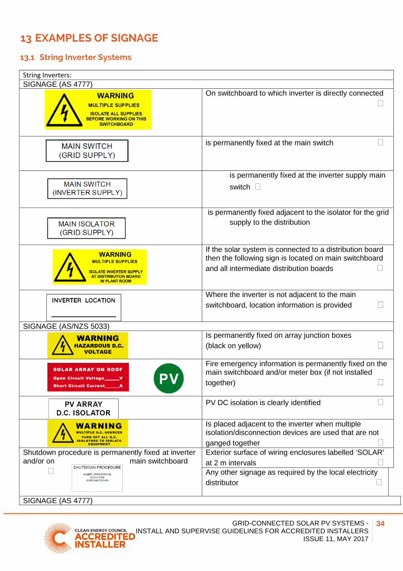
13.1 String Inverter Systems
String Inverters: SIGNAGE (AS 4777) On switchboard to which inverter is directly connected
is permanently fixed at the main switch
is permanently fixed at the inverter supply main switch
is permanently fixed adjacent to the isolator for the grid supply to the distribution
If the solar system is connected to a distribution board then the following sign is located on main switchboard and all intermediate distribution boards
Where the inverter is not adjacent to the main switchboard, location information is provided
SIGNAGE (AS/NZS 5033) Is permanently fixed on array junction boxes
(black on yellow)
Fire emergency information is permanently fixed on the main switchboard and/or meter box (if not installed together)
PV DC isolation is clearly identified
Is placed adjacent to the inverter when multiple isolation/disconnection devices are used that are not ganged together
Shutdown procedure is permanently fixed at inverter and/or on main switchboard
Exterior surface of wiring enclosures labelled ‘SOLAR’ at 2 m intervals Any other signage as required by the local electricity distributor
SIGNAGE (AS 4777)
GRID-CONNECTED SOLAR PV SYSTEMS - INSTALL AND SUPERVISE GUIDELINES FOR ACCREDITED INSTALLERS
ISSUE 11, MAY 2017
35
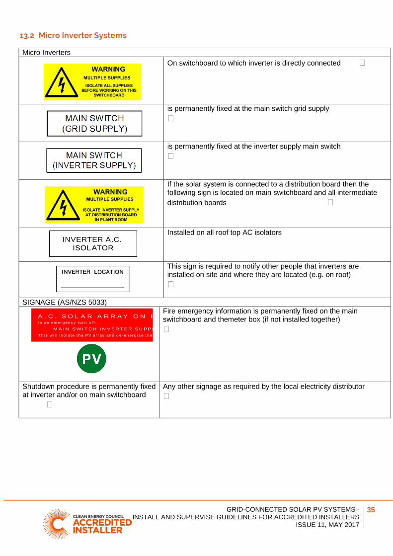
13.2 Micro Inverter Systems
Micro Inverters On switchboard to which inverter is directly connected
is permanently fixed at the main switch grid supply
is permanently fixed at the inverter supply main switch
If the solar system is connected to a distribution board then the following sign is located on main switchboard and all intermediate distribution boards
Installed on all roof top AC isolators
This sign is required to notify other people that inverters are installed on site and where they are located (e.g. on roof)
SIGNAGE (AS/NZS 5033)
Fire emergency information is permanently fixed on the main switchboard and themeter box (if not installed together)
Shutdown procedure is permanently fixed at inverter and/or on main switchboard
Any other signage as required by the local electricity distributor
INVERTER A.C. ISOLATOR
A . C . S O L A R A R R A Y O N RIn an em er g en c y t u r n o f f -
Th i s w i l l i s o l at e t h e PV ar r ay an d d e - en er g i s e t h e M A I N S W I T C H I N V E R T E R S U P P L
GRID-CONNECTED SOLAR PV SYSTEMS - INSTALL AND SUPERVISE GUIDELINES FOR ACCREDITED INSTALLERS
ISSUE 11, MAY 2017
36
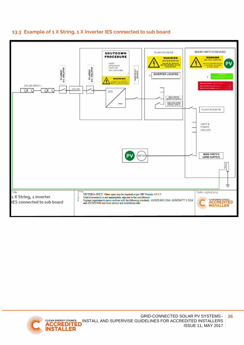
13.3 Example of 1 X String, 1 X Inverter IES connected to sub board
GRID-CONNECTED SOLAR PV SYSTEMS - INSTALL AND SUPERVISE GUIDELINES FOR ACCREDITED INSTALLERS
ISSUE 11, MAY 2017
37
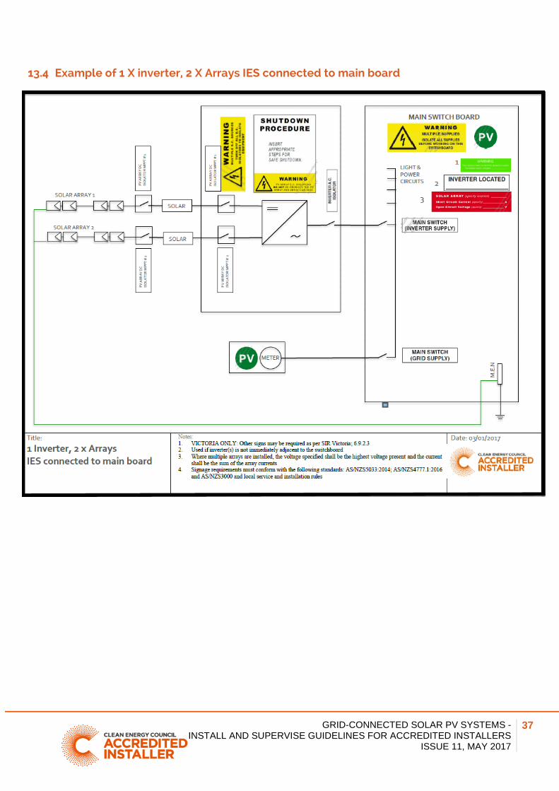
13.4 Example of 1 X inverter, 2 X Arrays IES connected to main board
GRID-CONNECTED SOLAR PV SYSTEMS - INSTALL AND SUPERVISE GUIDELINES FOR ACCREDITED INSTALLERS
ISSUE 11, MAY 2017
38
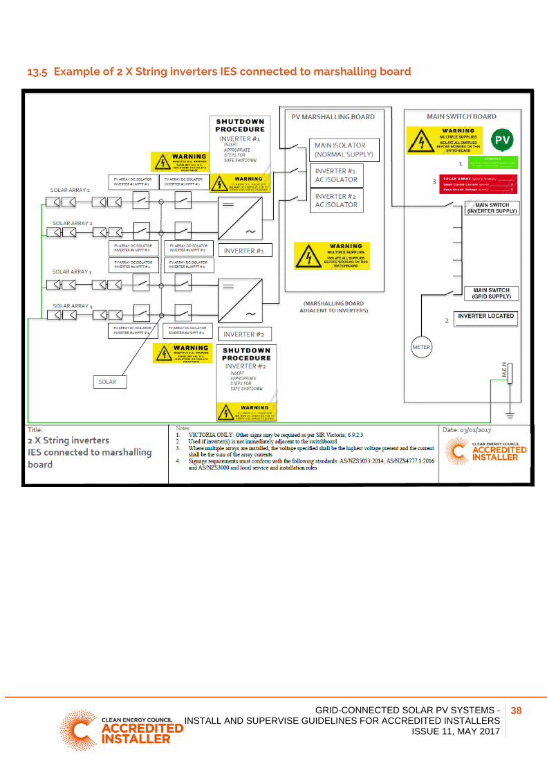
13.5 Example of 2 X String inverters IES connected to marshalling board
GRID-CONNECTED SOLAR PV SYSTEMS - INSTALL AND SUPERVISE GUIDELINES FOR ACCREDITED INSTALLERS
ISSUE 11, MAY 2017
39
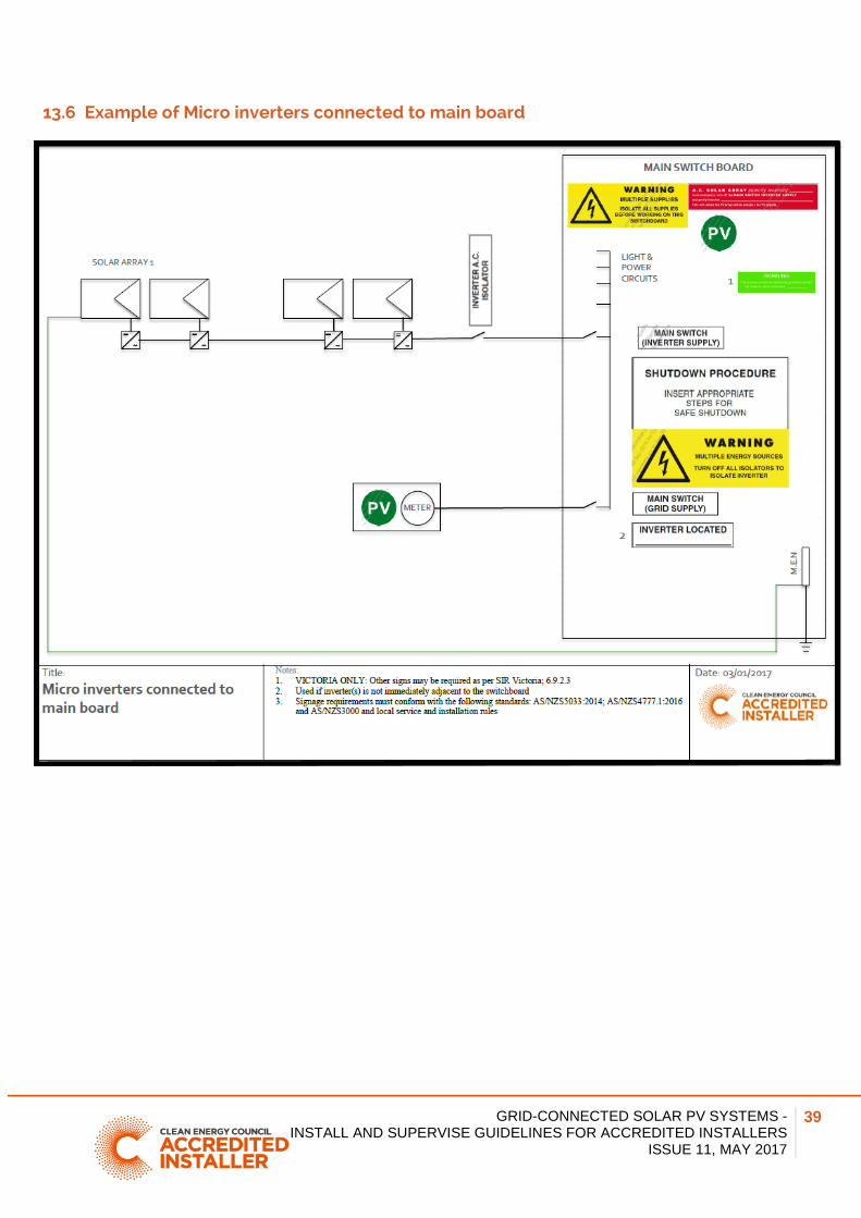
13.6 Example of Micro inverters connected to main board
GRID-CONNECTED SOLAR PV SYSTEMS - INSTALL AND SUPERVISE GUIDELINES FOR ACCREDITED INSTALLERS
ISSUE 11, MAY 2017
40
___________________________________________________________ 14 ATTACHMENT 1: DANGEROUS SITUATION
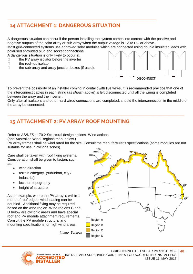
A dangerous situation can occur if the person installing the system comes into contact with the positive and negative outputs of the solar array or sub-array when the output voltage is 120V DC or above. Most grid-connected systems use approved solar modules which are connected using double insulated leads with polarised shrouded plug and socket connections. A dangerous situation is only likely to occur at: the PV array isolator before the inverter the roof-top isolator the sub-array and array junction boxes (if used). To prevent the possibility of an installer coming in contact with live wires, it is recommended practice that one of the interconnect cables in each string (as shown above) is left disconnected until all the wiring is completed between the array and the inverter. Only after all isolators and other hard wired connections are completed, should the interconnection in the middle of the array be connected. ______________________________________________________________________ 15 ATTACHMENT 2: PV ARRAY ROOF MOUNTING
Refer to AS/NZS 1170.2 Structural design actions- Wind actions (and Australian Wind Regions map, below.) PV array frames shall be wind rated for the site. Consult the manufacturer’s specifications (some modules are not suitable for use in cyclone zones). Care shall be taken with roof fixing systems. Consideration shall be given to factors such as:
• wind direction • terrain category (suburban, city /
industrial) • location topography • height of structure.
As an example, where the PV array is within 1 metre of roof edges, wind loading can be doubled. Additional fixing may be required based on the wind region. Wind regions C and D below are cyclonic areas and have special roof and PV module attachment requirements. Consult the PV module structural and mounting specifications for high wind areas.
Image: Sunlock
DISCONNECT