cleaver-brooks...cleaver-brooks model cb, cb-le packaged boiler 400 - 800 hp, light oil, heavy oil,...
TRANSCRIPT
CLEAVER-BROOKSModel CB, CB-LE Packaged Boiler
400 - 800 HP, Light Oil, Heavy Oil, Gas, or Combination
Operation and Maintenance Manual
Manual Number: 750-94
Release Date: December 2009

Copyright © 2009 by Cleaver-Brooks
All rights reserved. No part of this document may be reproduced, stored in a retrieval system, or transmitted in any form or by any means without the prior writ-
ten consent of Cleaver-Brooks.
Cleaver-Brooks
11950 West Lake Park Drive
Milwaukee, WI 53224
414-359-0600
www.cleaver-brooks.com

Model CB, CB-LE Packaged Boiler
750-94
Table of Contents
CHAPTER 1 Basics of Firetube Operation 1-11.1 — Introduction 1-1
1.2 — The Boiler 1-4
1.3 — Construction 1-5
1.4 — Steam Controls (All Fuels) 1-61.4.1 — Operating Limit Pressure Control 1-61.4.2 — High Limit Pressure Control 1-71.4.3 — Modulating Pressure Control 1-71.4.4 — Low Water Cutoff and Pump Control 1-71.4.5 — Water Column Assembly 1-81.4.6 — Water Column Drain Valve 1-81.4.7 — Water Gauge Glass Drain Valve 1-91.4.8 — Vent Valve 1-91.4.9 — Steam Pressure Gauge 1-91.4.10 — Auxiliary Low-Water Cutoff 1-91.4.11 — Safety Valve(s) 1-10
1.5 — Hot Water Controls (All Fuels) 1-111.5.1 — Water Pressure and Temperature Gauge 1-111.5.2 — Operating Limit Temperature Control 1-111.5.3 — High Limit Temperature Control 1-111.5.4 — Modulating Temperature Control 1-121.5.5 — Low-Water Cutoff 1-121.5.6 — Auxiliary Low-Water Cutoff (optional) 1-121.5.7 — Safety Valve(s) 1-12
750-94 (revised 2009)Model CB, CB-LE Packaged Boiler Manual
i

1.6 — IFGR Components 1-121.6.1 — Flue Gas Transfer Port, IFGR Damper, & Flange Collar 1-121.6.2 — IFGR Damper Linkage 1-131.6.3 — Over-Travel Mechanism 1-131.6.4 — Fuel Change-Over Linkage 1-131.6.5 — Fan/Motor Cassette 1-151.6.6 — Burner Drawer 1-151.6.7 — Combustion Air Inlet 1-151.6.8 — Front Door Insulation 1-16
CHAPTER 2 Burner Operation and Control 2-12.1 — The Burner 2-1
2.2 — Control and Component Function 2-2
2.3 — Components Common to All Boilers 2-3
2.4 — Controls for Gas Firing 2-7
2.5 — Controls Common to Oil-Fired Boilers 2-10
2.6 — Additional Controls for Heavy Oil 2-14
2.7 — Controls for Combination Burners Only 2-18
2.8 — Combustion Air 2-18
2.9 — Automatic Ignition 2-19
2.10 — Atomizing Air 2-19
2.11 — Oil Fuel Flow: Light Oil 2-20
ii 750-94 (revised 2009)Model CB, CB-LE Packaged Boiler Manual
2.12 — Oil Fuel Flow: Heavy Oil 2-22
2.13 — Gas Fuel Flow 2-24
2.14 — Modulating Firing 2-24
CHAPTER 3 Waterside Care and Requirements 3-13.1 — Overview 3-1
3.2 — Water Requirements: Hot Water Boiler 3-23.2.1 — Air Removal 3-2
3.2.1.1 — Minimum Water Temperature 3-23.2.1.2 — Rapid Replacement of Boiler Water 3-33.2.1.3 — Continuous Flow Through the Boiler 3-3
3.2.2 — Water Circulation 3-33.2.2.1 — Multiple Boiler Installations 3-43.2.2.2 — Pump Location 3-53.2.2.3 — Pump Operation 3-5
3.2.3 — Pressure 3-5
3.3 — Water Requirements: Steam Boiler 3-73.3.1 — Feed Pump Operation 3-73.3.2 — Water Feeder (optional) Operation 3-8
3.4 — Water Treatment 3-8
3.5 — Cleaning 3-93.5.1 — Hot Water and Steam Piping 3-93.5.2 — Pressure Vessel 3-9
3.6 — Boil-Out of a New Unit 3-10
750-94 (revised 2009)Model CB, CB-LE Packaged Boiler Manual
iii

3.7 — Washing Out 3-133.7.1 — Hot Water Boiler 3-133.7.2 — Steam Boiler 3-133.7.3 — Flushing of Pressure Vessel Interior 3-13
3.8 — Blowdown: Steam Boiler 3-143.8.1 — Intermittent Manual Blowdown 3-153.8.2 — Continuous Blowdown 3-153.8.3 — Frequency of Manual Blowdown 3-153.8.4 — Manual Blowdown Procedure 3-16
3.9 — Periodic Inspection 3-17
3.10 — Preparation for Extended Lay-Up 3-19
CHAPTER 4 Sequence of Operation 4-14.1 — Overview 4-1
4.2 — Circuit and Interlock Controls 4-2
4.3 — Sequence of Operation: Oil or Gas 4-44.3.1 — Pre-Purge Cycle 4-44.3.2 — Ignition Cycle 4-54.3.3 — Run Cycle 4-64.3.4 — Burner Shutdown: Post Purge 4-7
4.4 — Flame Loss Sequence 4-74.4.1 — No Pilot Flame 4-84.4.2 — Pilot But No Main Flame 4-84.4.3 — Loss of Flame 4-8
iv 750-94 (revised 2009)Model CB, CB-LE Packaged Boiler Manual

CHAPTER 5 Starting and Operating Instructions 5-15.1 — Overview 5-1
5.2 — Control Settings: Steam and Hot Water 5-35.2.1 — Operating Limit Control 5-35.2.2 — High Limit Control 5-35.2.3 — Modulating Control 5-35.2.4 — Low-Water Cutoff and Pump Control 5-45.2.5 — Additional Considerations 5-4
5.3 — Gas Pilot 5-4
5.4 — Atomizing Air 5-5
5.5 — Firing Preparations for No. 2 Oil (Series 100 - 200) 5-75.5.1 — Oil Flow 5-75.5.2 — Oil Pressure 5-95.5.3 — Starting 5-9
5.6 — Firing Preparation for No. 6 Oil (Series 400 - 600) 5-95.6.1 — Oil Flow 5-105.6.2 — Oil Pressure 5-115.6.3 — Oil Temperature 5-115.6.4 — Starting 5-12
5.7 — Firing Preparations for Gas (Series 200-400-700) 5-13
5.8 — IFGR Setup 5-15
5.9 — Startup, Operating and Shutdown: All Fuels 5-175.9.1 — Operating 5-195.9.2 — Shutdown 5-20
5.10 — Control Operational Test and Checks 5-20
750-94 (revised 2009)Model CB, CB-LE Packaged Boiler Manual
v
CHAPTER 6 Adjustment Procedures 6-16.1 — Overview 6-1
6.1.1 — High Turndown Burner 6-1
6.2 — Linkage: Modulating Motor and Air Damper 6-2
6.3 — Modulating Motor 6-5
6.4 — Modulating Motor Switches: Low-Fire and High-Fire 6-6
6.5 — Burner Operating Controls: General 6-6
6.6 — Modulating Pressure Control: Steam 6-10
6.7 — Operating Limit Pressure Control: Steam 6-10
6.8 — High Limit Pressure Control: Steam 6-10
6.9 — Modulating Temperature Control: Hot Water 6-11
6.10 — Operating Limit Temperature Control: Hot Water 6-12
6.11 — High Limit Temperature Control: Hot Water 6-12
6.12 — Low Water Cutoff Devices: Steam & Hot Water 6-12
6.13 — Combustion Air Proving Switch 6-12
6.14 — Atomizing Air Proving Switch 6-13
6.15 — Gas Pilot Flame Adjustment 6-146.15.1 — Measure and Adjust Pilot 6-14
vi 750-94 (revised 2009)Model CB, CB-LE Packaged Boiler Manual

6.16 — Gas Pressure and Flow Information 6-166.16.1 — Pressure 6-166.16.2 — Gas Flow 6-196.16.3 — Pressure Correction 6-196.16.4 — Checking Gas Flow 6-21
6.17 — Gas Fuel Combustion Adjustment 6-216.17.1 — Standard Burner Low-Fire Adjustment 6-256.17.2 — High Turndown Burner Low-Fire Adjustment 6-26
6.18 — Low-Gas Pressure Switch 6-26
6.19 — High-Gas Pressure Switch 6-27
6.20 — Fuel Oil Pressure and Temperature: General 6-27
6.21 — Fuel Oil Combustion Adjustment 6-296.21.1 — Standard Burner Low-Fire Adjustment: Heavy Oil 6-306.21.2 — High Turndown Burner Low-Fire Adjustment: Light Oil 6-31
6.22 — Burner Drawer Adjustment 6-31
6.23 — Oil Drawer Switch 6-33
6.24 — Low Oil Temperature Switch 6-33
6.25 — High Oil Temperature Switch (Optional) 6-34
6.26 — Low Oil Pressure Switch (Optional) 6-34
6.27 — Electric Oil Heater Thermostat (400 and 600 Series: Steam) 6-34
6.28 — Steam Oil Heater Thermostat: No. 6 Oil 6-35
6.29 — Hot Water Oil Heater Thermostat (400 and 600 Series) 6-35
750-94 (revised 2009)Model CB, CB-LE Packaged Boiler Manual
vii
6.30 — Steam Heater Pressure Regulator (400 and 600 Series: Steam) 6-35
CHAPTER 7 Troubleshooting 7-17.1 — Overview 7-1
CHAPTER 8 Inspection and Maintenance 8-18.1 — Overview 8-1
8.1.1 — Periodic Inspection 8-2
8.2 — Fireside Cleaning 8-3
8.3 — Water Level Controls 8-48.3.1 — Steam Boiler 8-48.3.2 — Hot Water Boiler 8-5
8.4 — Water Gauge Glass 8-5
8.5 — Electrical Controls 8-6
8.6 — Flame Safety Control 8-88.6.1 — Checking Pilot Flame Failure 8-98.6.2 — Checking Failure to Light Main Flame 8-98.6.3 — Checking Loss of Flame 8-10
8.7 — Oil Burner Maintenance 8-108.7.1 — Oil Strainers 8-108.7.2 — Light Oil Strainers 8-108.7.3 — Heavy Oil Strainers 8-118.7.4 — Cleaning the Oil Nozzle 8-118.7.5 — Cleaning Air Purge Nozzle (No. 6 Oil) and Back Pressure Orifice Nozzle (No. 2 Oil) 8-12
viii 750-94 (revised 2009)Model CB, CB-LE Packaged Boiler Manual

8.7.6 — Ignition System 8-12
8.8 — Gas Burner Maintenance 8-13
8.9 — Motorized Gas Valve 8-14
8.10 — Solenoid Valves 8-14
8.11 — Air Control Damper, Linkage, and Cam Spring 8-15
8.12 — Forced Draft Fan 8-16
8.13 — Fan/Motor Cassette Removal 8-18
8.14 — Inspection and Adjustment 8-20
8.15 — Airbox Gasket Installation 8-21
8.16 — Fan/Motor Cassette Installation 8-22
8.17 — Safety Valves 8-23
8.18 — Fuel Oil Metering Valve, Adjusting, Relief Valves 8-23
8.19 — Air Pump and Lubricating System 8-268.19.1 — Air Compressor 8-268.19.2 — Lubricating Oil 8-268.19.3 — Lubricating Oil Strainer and Cooling Coil 8-278.19.4 — Air Cleaner 8-278.19.5 — Air-Oil Tank 8-278.19.6 — Lube Oil Cooling Coil 8-288.19.7 — Flexible Coupling Alignment 8-288.19.8 — Air Compressor Replacement 8-30
8.19.8.1 — Dismantling 8-308.19.8.2 — Reassembly 8-31
750-94 (revised 2009)Model CB, CB-LE Packaged Boiler Manual
ix
8.20 — Refractory 8-328.20.1 — Furnace Liner 8-338.20.2 — Throat Tile and Liner Installation 8-348.20.3 — Installation 8-358.20.4 — Rear Door 8-378.20.5 — Front Inner Door 8-39
8.21 — Opening and Closing Rear Door 8-408.21.1 — Closing and Sealing 8-41
8.22 — Lubrication 8-418.22.1 — Electric Motors 8-418.22.2 — Control Linkage 8-438.22.3 — Solenoid and Motorized Valves 8-438.22.4 — IFGR Lubrication 8-43
8.23 — Oil Heater: Electric, Steam, Hot Water 8-44
8.24 — Combustion 8-45
8.25 — Recommended Boiler Inspection Schedule 8-46
CHAPTER 9 Parts Lists and Drawings 9-19.1 — Ordering Parts 9-1
9.2 — Parts 9-29.2.1 — Air Compressor and Piping 9-29.2.2 — Air Compressor 9-39.2.3 — Air Line Piping 9-49.2.4 — Alstrom Heater 9-59.2.5 — Burner Housing Support 9-79.2.6 — Control Panel 9-99.2.7 — Entrance Box 9-119.2.8 — Front Davit 9-129.2.9 — Front Head Linkage 9-139.2.10 — Heavy Oil Piping 9-14
x 750-94 (revised 2009)Model CB, CB-LE Packaged Boiler Manual
9.2.11 — Standard Impeller 9-169.2.12 — Front Head (Electrical) 9-179.2.13 — Pressure Controls 9-199.2.14 — Oil/Air Piping, Front Head (Light Oil) 9-209.2.15 — Rear Head Sealing-Davit 9-229.2.16 — Furnace Liner/Bricking 9-239.2.17 — Throat Tile and Furnace Liner 9-259.2.18 — Blower Assembly 9-279.2.19 — Temperature Controls 9-30
CHAPTER 10 Gas Train Parts Lists 10-110.1 — Standard Main Gas Train 10-1
10.2 — Starter Gas Train Butterfly Valve: All Boilers 10-1
10.3 — Pilot Gas Trains: All Boilers 10-210.3.1 — Standard & CSD-1 Pilot Gas Train 10-210.3.2 — NFPA85 Pilot Gas Train 10-2
10.4 — Standard Main Gas Trains 10-310.4.1 — 60, 30, &20 PPM Standard Main Gas Train 10-310.4.2 — 60, 30, & 20 PPM W/NFPA-85 10-510.4.3 — 60, 30, & 20 PPM, 600 HP Standard Main Gas Train 10-610.4.4 — 60, 30, & 20 PPM, 600 HP W/NFPA-85 10-710.4.5 — 60, 30, & 20* PPM, 700 & 800 HP Standard Main Gas Train 10-860, 30, & 20* PPM, 700 & 800 HP W/FM 10-810.4.6 — 60, 30, & 20* PPM, 700 & 800 HP Standard Main Gas Train W/NFPA-85 10-9
750-94 (revised 2009)Model CB, CB-LE Packaged Boiler Manual
xi

xii 750-94 (revised 2009)Model CB, CB-LE Packaged Boiler Manual

PREFACE
te the
Safety PrecautionsIt is essential to read and understand the following safety precautions before attempting to opera
xiii
equipment. Failure to follow these precautions may result in damage to equipment, serious injury, or death. A complete understanding of this manual is required before attempting to startup, operate, or
ing
d,
750-94 (revised 2009)Model CB, CB-LE Packaged Boiler Manual
maintain the equipment. The equipment should be operated only by personnel who have a workknowledge and understanding of the equipment.
The following symbols are used throughout this manual:
This symbol indicates a potentially hazardous situation which, if not recognized and addressecould result in serious injury or death.
Important!
! Warning
2009)anual
quip- rate
ailure
r per-
the eir
This symbol indicates a potentially hazardous situation which, if not recognized and addressed,
s
! Caution
xiv 750-94 (revisedModel CB, CB-LE Packaged Boiler M
To Owners, Operators, and Maintenance PersonnelThis operating manual presents information that will help to properly operate and care for the ement. Study its contents carefully. The unit will provide good service and continued operation ifproper operating and maintenance instructions are followed. No attempt should be made to opethe unit until the principles of operation and all of the components are thoroughly understood. Fto follow all applicable instructions and warnings may result in severe injury or death.
It is the responsibility of the owner to train and advise, in all aspects of safety, not only his or hesonnel, but the contractors’ personnel who are servicing, repairing, or operating the equipment.
Cleaver-Brooks equipment is designed and engineered to give long life and excellent service on job. The electrical and mechanical devices supplied as part of the unit were chosen because of th
could result in damage to the equipment.
NOTE: This symbol indicates information that is vital to the operation of the equipment.
• Do not operate, service, or repair this equipment unless you fully understand all applicable sectionof this manual.
• Do not allow others to operate, service, or repair this equipment unless they fully understand all applicable sections of this manual.
• Failure to follow all applicable warnings and instructions may result in severe injury or death.
! Warning

xv
To Owners, Operators, and Maintenance Personnel
known ability to perform, however, proper operating techniques and maintenance procedures must be followed at all times. Although these components afford a high degree of protection and safety, oper-ation of equipment is not to be considered free from all dangers and hazards inherent in handling and firing of fuel.
y. he
unt ded
, a ce, or
ty
oper-indef- these
valu-
pha-llow nter-water r the
ld be
750-94 (revised 2009)Model CB, CB-LE Packaged Boiler Manual
Any “automatic” features included in the design do not relieve the attendant of any responsibilitSuch features merely free him of certain repetitive chores and give him more time to devote to tproper upkeep of equipment.
It is solely the operator’s responsibility to properly operate and maintain the equipment. No amoof written instructions can replace intelligent thinking and reasoning and this manual is not intento relieve the operating personnel of the responsibility for proper operation. On the other handthorough understanding of this manual is required before attempting to operate, maintain, servirepair this equipment.
Because of state, local, or other applicable codes, there are a variety of electric controls and safedevices which vary considerably from one boiler to another. This manual contains information designed to show how a basic burner operates.
Operating controls will normally function for long periods of time and we have found that someators become lax in their daily or monthly testing, assuming that normal operation will continue initely. Malfunctions of controls lead to uneconomical operation and damage and, in most cases,conditions can be traced directly to carelessness and deficiencies in testing and maintenance.
It is recommended that a boiler room log or record be maintained. Recording of daily, weekly, monthly, and yearly maintenance activities and recording of any unusual operation will serve as aable guide to any necessary investigation.
Most instances of major boiler damage are the result of operation with low water. We cannot emsize too strongly the need for the operator to periodically check his low water controls and to fogood maintenance and testing practices. Cross-connecting piping to low water devices must be inally inspected periodically to guard against any stoppages which could obstruct the free flow of to the low water devices. Float bowls of these controls must be inspected frequently to check fopresence of foreign substances that would impede float ball movement.
The waterside condition of the pressure vessel is of extreme importance. Waterside surfaces shouinspected frequently to check for the presence of any mud, sludge, scale, or corrosion.

2009)anual
The services of a qualified water treating company or a water consultant to recommend the proper boiler water treating practices are essential.
The operation of this equipment by the owner and his or her operating personnel must comply with all requirements or regulations of the owner’s insurance company and/or other authority having juris-
gs or
xvi 750-94 (revisedModel CB, CB-LE Packaged Boiler M
diction. In the event of any conflict or inconsistency between such requirements and the warnininstructions contained herein, please contact Cleaver-Brooks before proceeding.

CHAPTER 1 Basics of Firetube Operation
1.1 — IntroductionFiretube boilers are available for low or high pressure steam, or for hot water applications. Firetube boilers are typically used for applications ranging from 15 to 800 horsepower. A firetube boiler is a cylindrical vessel, with horizontal tubes passing through and connected to the front and rear tube sheets. The vessel contains the water and absorbs the energy generated from the flame. The front door and rear door provide the seal to contain the hot combustion gasses. Baffles designed into the doors serve to redirect the combustion gasses through the various firetube passages. The flame originates in the fur-nace. As the combustion gasses travel down the furnace and through the various firetube channels, heat from the flame and combustion gasses is transferred to the water. Transferred energy develops into the required steam or hot water. The pri-mary purpose of the boiler is to supply energy to the facility’s operations — for heat, manufacturing processes, laundry, kitchen, etc. The nature of the facility’s operation will dictate whether aa steam or hot water boiler should be used.
The general information in this manual applies directly to Cleaver-Brooks Model CB Boilers in sizes ranging from 400 through 800 boiler horsepower for the following fuels:
Series 100 Light Oil (No. 2) onlySeries 200 Light Oil (No. 2) or GasSeries 400 Heavy Oil (No. 6) or GasSeries 600 Heavy Oil (No. 6) onlySeries 700 Gas only
NOTE: Although the Series 400 or 600 burner is designed and designated to burn No. 6 oil, the burner will handle grades 4 and 5 equally well, with some possible modifications. While the manual contains pertinent information on No. 6 fuel oil, all ref-erences to No. 6 fuel should be considered applicable to all grades of heavy oil.
750-94 (revised 2009)Model CB, CB-LE Packaged Boiler Manual
1-1

Basics of Firetube Operation
FIGURE 1-1. Firetube Boiler (cutaway view)
The LE option, available on Cleaver-Brooks firetube boilers, reduces nitrogen oxide (NOX) emissions, a major precursor to ozone pollution (smog). Carbon monoxide (CO) emissions also tend to be lower, die to increased turbulence caused by the addition of the flue gasses into the combustion air stream, thereby improving combustion.
Rated Capacity 400 through 800 hp
Operating Pressure Steam: 15 - 250 psig, or higher if specifiedHot Water: 30 - 250 psig, or higher if specified
Fuel Oil or Gas or CombinationIgnition AutomaticFiring Full Modulation Through Operating RangesBurner (Oil) (Low Pressure) Air AtomizingBurner (Gas) Non-premix, Orificed TypeAir Damper Rotary Type (Electrically Modulated)Steam Trim ASME CodeWater Trim ASME Code
1-2 750-94 (revised 2009)Model CB, CB-LE Packaged Boiler Manual

1.2 — The Boiler
The LE Option is used on Cleaver-Brooks Model CB firetube boilers firing either natural gas and/or light oil, and is com-patible with both hot water and steam systems.
The IFGR system mixes a portion of the relatively cool flue gas from the exit of the fourth-pass tubes with the incoming combustion air to reduce the furnace flame temperature, thereby reducing NOX emissions. In this approach, the combus-tion air fan handles both the combustion air and the recirculated flue gasses. Accordingly, this method is called Induced Flue Gas Recirculation (IFGR) because the flue gas is “induced” into the fan inlet.
The LE Option, with its various levels of IFGR systems, can affect the selection of the combustion air fan, motor, burner, and other components. Several different system configurations are available, depending on the requirements for NOX emis-sions and the fuels used. All systems use similar primary components, but may have different linkage controls, IFGR damper, fan, and motor sizes.
Always order genuine Cleaver-Brooks parts from your local Cleaver-Brooks authorized representative.
The boiler and related equipment installation are to be in compliance with the standards of the National Board of Fire Underwriters. Installation should also conform to state and local codes governing such equipment. Prior to installation, the proper authorities having jurisdiction are to be consulted, permits obtained, etc. All boilers in the above series comply, when equipped with optional equipment, to Industrial Risk Insurers (IRI), Factory Mutual (FM), or other insuring underwriters requirements.
1.2 — The BoilerThe Model CB boiler is a packaged firetube boiler of welded steel construction and consists of a pressure vessel, burner, burner controls, forced draft fan, damper, air pump, refractory, and appropriate boiler trim.
The horsepower rating of the boiler is indicated by the numbers following the fuel series. Thus, CB700-600 identifies a gas-fired 600 hp boiler.
The firetube construction provides some characteristics that differentiate it from other boiler types. Because of its vessel size, the firetube contains a large amount of water, allowing it to respond to load changes with minimum variation in steam pressure.
Firetube boilers are rated in boiler horsepower (BHP), which should not be confused with other horsepower measurements.
Hot water is commonly used in heating applications with the boiler supplying water to the system at 180º F to 220º F. The operating pressure for hot water heating systems usually in 30 psig to 125 psig.
Steam boilers are designed for low pressure or high pressure applications. Low pressure boilers are limited to 15 psig design, and are typically used for heating applications. High pressure boilers are typically used for process loads and can have a design pressure of 75 to 350 psig.
Steam and hot water boilers are defined according to design pressure and operating pressure. Design pressure is the maxi-mum pressure used in the design of the boiler for the purpose of calculating the minimum permissible thickness or physical characteristics of the pressure vessel parts of the boiler. Typically, the safety valves are set at or below design pressure. Oper-ating pressure is the pressure of the boiler at which it normally operates. The operating pressure usually is maintained at a suitable level below the setting of the pressure relieving valve(s) to prevent their frequent opening during normal operation.
750-94 (revised 2009)Model CB, CB-LE Packaged Boiler Manual
1-3

Basics of Firetube Operation
The type of service that your boiler is required to provide has an important bearing on the amount of waterside care it will require.
Feedwater equipment should be checked and ready for use. Be sure that all valves, piping, boiler feed pumps, and receivers are installed in accordance with prevailing codes and practices.
Water requirements for both steam and hot water boilers are essential to boiler life and length of service. Constant attention to water requirements will pay dividends in the form of longer life, less downtime, and prevention of costly repairs. Care taken in placing the pressure vessel into initial service is vital. The waterside of new boilers and new or remodeled steam or hot water systems may contain oil, grease, or other foreign matter. A method of boiling out the vessel to remove accumula-tions is described in Chapter 3.
The operator should be familiar with Chapter 3 before attempting to place the unit into operation.
1.3 — ConstructionSteam boilers designed for 15 psig and hot water boilers designed for 250º F at 125 psi or less are constructed in accordance with Section IV, Power Boilers, of ASME Code.
Steam boilers designed for operating pressures exceeding 15 psig are constructed in accordance with Section 1, Power Boil-ers, of the ASME Code. hot water boilers designed for operating temperatures above 250º F or 125 psi are likewise built to ASME Code.
Waterside care is of prime importance. For specific information or assistance with your water treatment requirements, con-tact your Cleaver-Brooks service and parts representative. Failure to follow these instructions could result in equipment damage.
! Caution
1-4 750-94 (revised 2009)Model CB, CB-LE Packaged Boiler Manual

1.4 — Steam Controls (All Fuels)
FIGURE 1-2. Steam Boiler: Light Oil or Gas Fired
1.4 — Steam Controls (All Fuels)
1.4.1 — Operating Limit Pressure Control
Breaks a circuit to stop burner operation on a rise of boiler pressure at a selected setting. It is adjusted to stop or start the burner at a preselected pressure setting.
1.4.2 — High Limit Pressure Control
Breaks a circuit to stop burner operation on a rise of pressure above a selected setting. It is adjusted to stop the burner at a preselected pressure above the operating limit control setting. The high limit pressure control is normally equipped with a manual reset.
750-94 (revised 2009)Model CB, CB-LE Packaged Boiler Manual
1-5
Basics of Firetube Operation
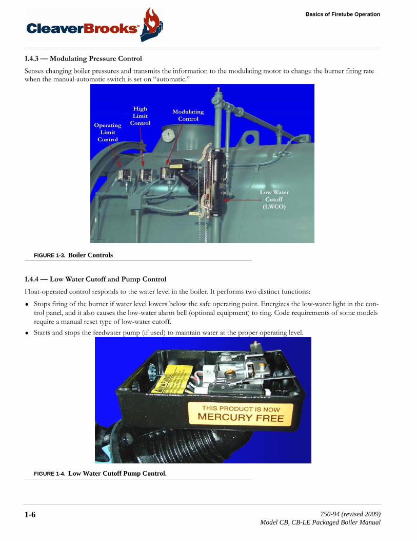
1.4.3 — Modulating Pressure Control
Senses changing boiler pressures and transmits the information to the modulating motor to change the burner firing rate when the manual-automatic switch is set on “automatic.”
FIGURE 1-3. Boiler Controls
1.4.4 — Low Water Cutoff and Pump Control
Float-operated control responds to the water level in the boiler. It performs two distinct functions:
• Stops firing of the burner if water level lowers below the safe operating point. Energizes the low-water light in the con-trol panel, and it also causes the low-water alarm bell (optional equipment) to ring. Code requirements of some models require a manual reset type of low-water cutoff.
• Starts and stops the feedwater pump (if used) to maintain water at the proper operating level.
FIGURE 1-4. Low Water Cutoff Pump Control.
1-6 750-94 (revised 2009)Model CB, CB-LE Packaged Boiler Manual

1.4 — Steam Controls (All Fuels)
1.4.5 — Water Column Assembly
Houses the low-water cutoff and pump control and includes the water gauge glass and gauge glass shutoff cock.
1.4.6 — Water Column Drain Valve
Provided so that the water column and its piping can be flushed regularly to assist in maintaining cross-connecting piping and in keeping the float bowl clean and free of sediment. A similar drain valve is furnished with auxiliary low-water cutoff for the same purpose.
1.4.7 — Water Gauge Glass Drain Valve
Provided to flush the gauge glass.
FIGURE 1-5. Water Column Assembly & LWCO
1.4.8 — Vent Valve
Allows the boiler to be vented during filling, and facilitates routine boiler inspection as required by ASME Code.
1.4.9 — Steam Pressure Gauge
Indicates boiler internal pressure.
Determine that the main and auxiliary low water cutoffs and pump control are level after installation and throughout the equip-ment’s operating life. Failure to follow these instructions could result in equipment damage.
! Caution
750-94 (revised 2009)Model CB, CB-LE Packaged Boiler Manual
1-7

Basics of Firetube Operation
1.4.10 — Auxiliary Low-Water Cutoff
Breaks the circuit to stop burner operation in the event boiler water drops below the master low-water cutoff point. Manual reset type requires manual resetting in order to start the burner after a low-water condition.
1.4.11 — Safety Valve(s)
Prevents buildup over the design pressure of the pressure vessel. The size, rating, and number of valves on a boiler is deter-mined by the ASME Boiler Code. The safety valve and the discharge piping are to be installed to conform to the ASME Code requirements. The installation of a valve is of primary importance to its service life. A valve must be mounted in a ver-tical position so that discharge piping and code required drains can be properly piped to prevent buildup of back pressure and accumulation of foreign material around the valve seat area. Apply only a moderate amount of pipe compound to male threads and avoid overtightening, which can distort the seats. Use only flat-jawed wrenches on the flats provided. When installing a flange-connected valve, use a new gasket and draw the mounting bolts down evenly. Do not install or remove side outlet valves by using a pipe or wrench in the outlet.
FIGURE 1-6. Safety Valve
Only properly qualified personnel such as the safety valve manufacturer’s certified representative can adjust or repair the boiler safety valves. Failure to follow these instructions could result in serious injury or death.
! Warning
1-8 750-94 (revised 2009)Model CB, CB-LE Packaged Boiler Manual

1.5 — Hot Water Controls (All Fuels)
1.5 — Hot Water Controls (All Fuels)
1.5.1 — Water Pressure and Temperature Gauge
Indicates the internal water pressure and the boiler water temperature.
FIGURE 1-7. Water Pressure and Temperature Gauge & Limit Controls (configurations will vary)
1.5.2 — Operating Limit Temperature Control
Breaks a circuit to stop burner operation on a rise of boiler temperature at a selected setting. It is adjusted to stop or start the burner at a preselected operating temperature.
1.5.3 — High Limit Temperature Control
Breaks a circuit to stop burner operation on a rise of temperature at a selected setting. It is adjusted to stop burner at a pre-selected temperature above the operating control setting. The high limit temperature control normally is equipped with a manual reset.
1.5.4 — Modulating Temperature Control
Senses changing boiler water temperature and transmits the information to the modulating motor to change the burner fir-ing rate when the manual-automatic switch is set on “automatic.”
1.5.5 — Low-Water Cutoff
Breaks the circuit to stop burner operation if the water level in the boiler drops below a safe operating point, activating a low-water light and optional alarm bell if burner is so equipped.
1.5.6 — Auxiliary Low-Water Cutoff (optional)
Breaks the circuit to stop burner operation if the water level in the boiler drops below the master low-water cutoff point.
750-94 (revised 2009)Model CB, CB-LE Packaged Boiler Manual
1-9
Basics of Firetube Operation
1.5.7 — Safety Valve(s)
Relieves the boiler of pressure higher than the design pressure or a lower pressure, if designated. Relief valves and their dis-charge piping are to be installed to conform to ASME Code requirements.
1.6 — IFGR Components
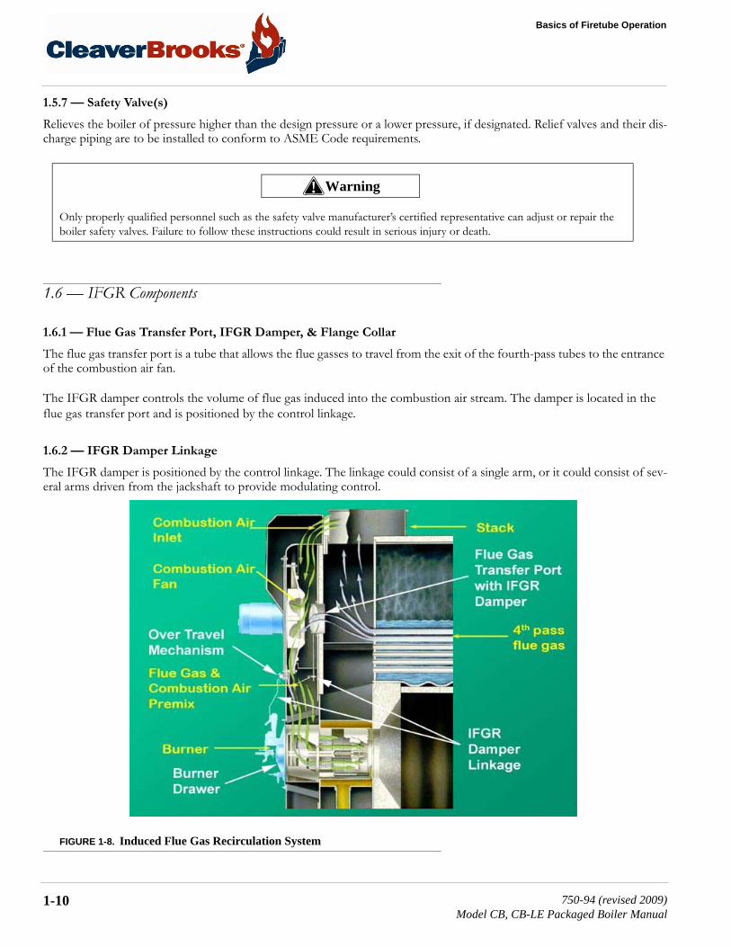
1.6.1 — Flue Gas Transfer Port, IFGR Damper, & Flange Collar
The flue gas transfer port is a tube that allows the flue gasses to travel from the exit of the fourth-pass tubes to the entrance of the combustion air fan.
The IFGR damper controls the volume of flue gas induced into the combustion air stream. The damper is located in the flue gas transfer port and is positioned by the control linkage.
1.6.2 — IFGR Damper Linkage
The IFGR damper is positioned by the control linkage. The linkage could consist of a single arm, or it could consist of sev-eral arms driven from the jackshaft to provide modulating control.
FIGURE 1-8. Induced Flue Gas Recirculation System
Only properly qualified personnel such as the safety valve manufacturer’s certified representative can adjust or repair the boiler safety valves. Failure to follow these instructions could result in serious injury or death.
! Warning
1-10 750-94 (revised 2009)Model CB, CB-LE Packaged Boiler Manual

1.6 — IFGR Components
1.6.3 — Over-Travel Mechanism
The over-travel mechanism has two functions. It allows the linkage to pass through the front door, and it allows jackshaft rotation to exceed (over-travel) IFGR linkage movement. A set of springs allows the linkage to stay in a fixed position while the jackshaft rotates.
1.6.4 — Fuel Change-Over Linkage
When a boiler is equipped to fire either gas or oil (dual fuel boilers), and the required NOX levels are below 60 ppm on nat-ural gas, a dual linkage arrangement is used to provide the different recirculation rates required for each fuel. Two jackshaft drive arms are provided, one for oil and one for gas. The linkage is manually connected to the appropriate arm, based on the fuel being used.
On dual fuel boilers with two jackshaft drive arms, as defined above, a proximity switch is used to prove that the correct linkage connection is made. (Refer to the wiring diagram provided with the boiler.)
FIGURE 1-9. Damper Linkage
750-94 (revised 2009)Model CB, CB-LE Packaged Boiler Manual
1-11

Basics of Firetube Operation
1.6.5 — Fan/Motor Cassette
The fan and motor assemblies are designed as a cassette so that they can be removed from the front of the boiler without opening the front door. The front door davit arm can be used to remove the assembly.
FIGURE 1-10. Fan/Motor Cassette
1.6.6 — Burner Drawer
The as spudding pattern for the IFGR system may be different than that of a non-IFGR, High-Turndown CB Burner of the same horsepower (HP) model designation.
1.6.7 — Combustion Air Inlet
The combustion air inlets are located at the top of the front door. Air enters from the rear of the air inlet shrouds, which reduces the sound level and captures heat from the boiler and stack flue outlet.
1.6.8 — Front Door Insulation
If NOX emissions are below 60 ppm, the front door is insulated inside to control temperature build up. The insulation is held in place with wire mesh.
1-12 750-94 (revised 2009)Model CB, CB-LE Packaged Boiler Manual

CHAPTER 2 Burner Operation and Control
2.1 — The BurnerThe oil burner is of the low pressure, air atomizing (nozzle) type. The gas burner is of the non-premix orifice type. The burners are ignited by a spark ignited gas pilot. The pilot is of the interrupted type and is extinguished after main flame is established.
Burners equipped to burn oil and gas (combination burners) include equipment for each distinct fuel. Since the burner uses only one type of fuel at a time, a gas/oil selector switch is incorporated.
Regardless of which fuel is used, the burner operates with full modulation (within its rated operating range). The burner returns to minimum firing position for ignition. High-pressure boilers (above 15 psi) can be wired for both low-pressure and high-pressure modulation, which enables the boiler to operate at lower pressure during off-load hours, but at a some-what reduced steam output, dependent upon lower steam pressure and steam nozzle sizing.
The flame safeguard and program relay include a flame detector to supervise both oil and gas flames, and to shut the burner down in the event of loss of flame. The programming portion of the control provides a pre-purging period, proving of the pilot and main flame, and a period of continued blower operation to post-purge the boiler of all unburned fuel vapor. Other safety controls shut down the burner under low-water conditions, excess steam pressure, or water temperature.
Safety interlock controls include combustion and atomizing air proving switches and, depending upon the fuel and insur-ance carrier requirements, controls that prove the presence of adequate fuel pressure, plus temperature proving controls when heated fuel oil is used.
The sequence of burner operation from startup through shutdown is governed by the program relay in conjunction with the operating, limit, and interlock devices. The devices are wired into the circuitry to provide safe operation and protect against incorrect operating techniques.
All CB boilers have the burner assembly attached to the front head. The entire head may be swung open for inspection and maintenance.
Combustion air is provided by a centrifugal blower located in the front head. Combustion air delivery to the burner is under the control of the damper motor. The motor also regulates the flow of fuel through a linkage system connected to the gas
NOTE: A Series 100 boiler is usually equipped with a light oil pilot, although a gas pilot is also available.
750-94 (revised 2009)Model CB, CB-LE Packaged Boiler Manual
2-1

Burner Operation and Control
butterfly valve and/or oil through a cam operated metering valve. Fuel input and air are thus properly proportioned for most efficient combustion.
Filtered primary air for atomizing fuel oil is furnished independently of combustion air by an air compressor. The burner control circuit operates on 115 volt, single phase 60 Hz (or 50 Hz when equipped) alternating current.
The forced draft fan motor is generally operated on 3-phase service at the available main power supply voltage.
Indicator lights signaling load demand, fuel valve, low water, and flame failure conditions are standard equipment.
In addition to the standard basic controls supplied, other devices may be required to meet specific requirements of an insur-ance carrier or local code. Refer to the Wiring Diagram (WD) prepared by Cleaver-Brooks for your specific installation to determine the specific controls in the burner and limit control circuits. The function of individual components is outlined in this chapter and the electrical sequence is covered in Chapter 3.
2.2 — Control and Component FunctionThe term “control” covers the more important valves and components, including, but not limited to, electrical controls or those monitored by the program relay. The operator must become familiar with the individual functioning of all controls before understanding boiler operation and procedures outlined in this manual.
The actual controls furnished with any given boiler will depend upon the type of fuel for which it is equipped, and whether it is a hot water or steam boiler. Refer to the applicable group or groups within this chapter that apply to the particular boiler.
NOTE: Boilers with optional features may have control components not listed here.
2-2 750-94 (revised 2009)Model CB, CB-LE Packaged Boiler Manual

2.3 — Components Common to All Boilers
2.3 — Components Common to All Boilers
FIGURE 2-1. Boiler Components
Component Description
Forced Draft Fan Motor Drives forced draft fan directly to provide combustion air. Also referred to as a blower motor.
Forced Draft Fan Provides all air, under pressure, for combustion of pilot fuel and main fuel, and for purging.
Modulating Motor Operates the rotary air damper and fuel metering valves through a cam and linkage system to provide proper air/fuel ratios under all boiler load conditions.
Modulating Motor Transformer (located in the modulating motor)
Reduces control circuit voltage (115 Vac) to required volt-age (24 Vac) for operation of the modulating motor.
Forced Draft Fan Motor Starter Energizes forced draft fan (blower) motor.Ignition Transformer Provides high voltage spark for ignition of gas pilot or light
oil pilot.Low Fire Switch An internal auxiliary switch, cam actuated by the motor
shaft, which must be closed to indicate that the air damper and fuel metering valve are in the low fire position before an ignition cycle can occur.
750-94 (revised 2009)Model CB, CB-LE Packaged Boiler Manual
2-3

Burner Operation and Control
Atomizing Air Proving Switch A pressure sensitive switch actuated by air pressure from the air pump. Its contacts close to prove presence of atom-izing air. The fuel valves cannot be energized unless this switch is satisfied.
Manual-Automatic Switch When set at “automatic,” subsequent operation is at the command of the modulating control, which governs the position of the modulating motor in accordance with load demand. When set at “manual,” the modulating motor, through the manual flame control, can be positioned at a desired burner firing rate. The primary purpose of the man-ual position is for testing and setting the air/fuel ratio through the entire firing range.
Manual Flame Control A manually operated potentiometer that permits the posi-tioning of the modulating motor to a desired burner firing rate when the manual-automatic switch is set on “manual.” It is used primarily for initial or subsequent setting of fuel input throughout the firing range. It has no control over the firing rate when the manual-automatic switch is set on “automatic.”
Burner Switch A manually operated start-stop switch for directly starting and stopping burner operation.
Flame Detector Monitors gas or oil pilot and energizes the programmer flame relay in response to a flame signal. It continues to monitor main flame (oil or gas) after expiration of pilot providing period. a standardly equipped boiler has a lead sulfide (infrared sensitive) detector.
Combustion Air Proving Switch A pressure sensitive switch actuated by air pressure from the forced draft fan. Its contacts close to prove presence of combustion air. The fuel valves cannot be energized unless this switch is satisfied.
Alarm Sounds to notify the operator of a condition requiring attention. The alarm is available as optional equipment.
Stack Thermometer Indicates temperature of vented flue gasses.Diffuser A circular plate, located at the furnace end of the burner
drawer, that imparts a rotary swirling motion to combus-tion air immediately prior to its entering the flame, thus providing a thorough and efficient mixture with the fuel.
Rotary Air Damper Provides accurate control of combustion air in proportion to fuel input for various load demands. It consists of two concentric cylinders with openings. The outer is stationary. The inner is rotated, under control of the modulating motor, to vary the effective size of the openings where they overlap.
Component Description
2-4 750-94 (revised 2009)Model CB, CB-LE Packaged Boiler Manual
2.4 — Controls for Gas Firing
2.4 — Controls for Gas Firing
Depending upon the requirements of the insurance carrier or other governing agencies, the gas flow control system, or gas train, may consist of some, or all, of the items listed below.
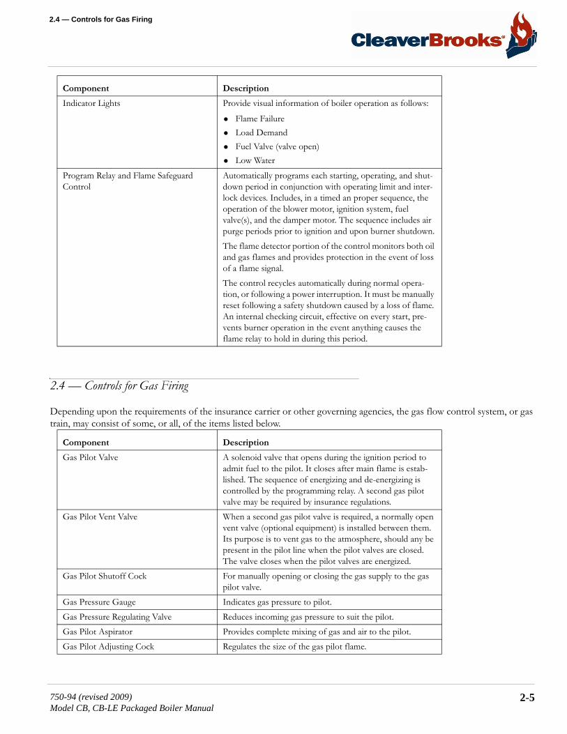
Indicator Lights Provide visual information of boiler operation as follows:
• Flame Failure• Load Demand• Fuel Valve (valve open)• Low Water
Program Relay and Flame Safeguard Control
Automatically programs each starting, operating, and shut-down period in conjunction with operating limit and inter-lock devices. Includes, in a timed an proper sequence, the operation of the blower motor, ignition system, fuel valve(s), and the damper motor. The sequence includes air purge periods prior to ignition and upon burner shutdown.The flame detector portion of the control monitors both oil and gas flames and provides protection in the event of loss of a flame signal.The control recycles automatically during normal opera-tion, or following a power interruption. It must be manually reset following a safety shutdown caused by a loss of flame. An internal checking circuit, effective on every start, pre-vents burner operation in the event anything causes the flame relay to hold in during this period.
Component Description
Gas Pilot Valve A solenoid valve that opens during the ignition period to admit fuel to the pilot. It closes after main flame is estab-lished. The sequence of energizing and de-energizing is controlled by the programming relay. A second gas pilot valve may be required by insurance regulations.
Gas Pilot Vent Valve When a second gas pilot valve is required, a normally open vent valve (optional equipment) is installed between them. Its purpose is to vent gas to the atmosphere, should any be present in the pilot line when the pilot valves are closed. The valve closes when the pilot valves are energized.
Gas Pilot Shutoff Cock For manually opening or closing the gas supply to the gas pilot valve.
Gas Pressure Gauge Indicates gas pressure to pilot.Gas Pressure Regulating Valve Reduces incoming gas pressure to suit the pilot.Gas Pilot Aspirator Provides complete mixing of gas and air to the pilot.Gas Pilot Adjusting Cock Regulates the size of the gas pilot flame.
Component Description
750-94 (revised 2009)Model CB, CB-LE Packaged Boiler Manual
2-5

Burner Operation and Control
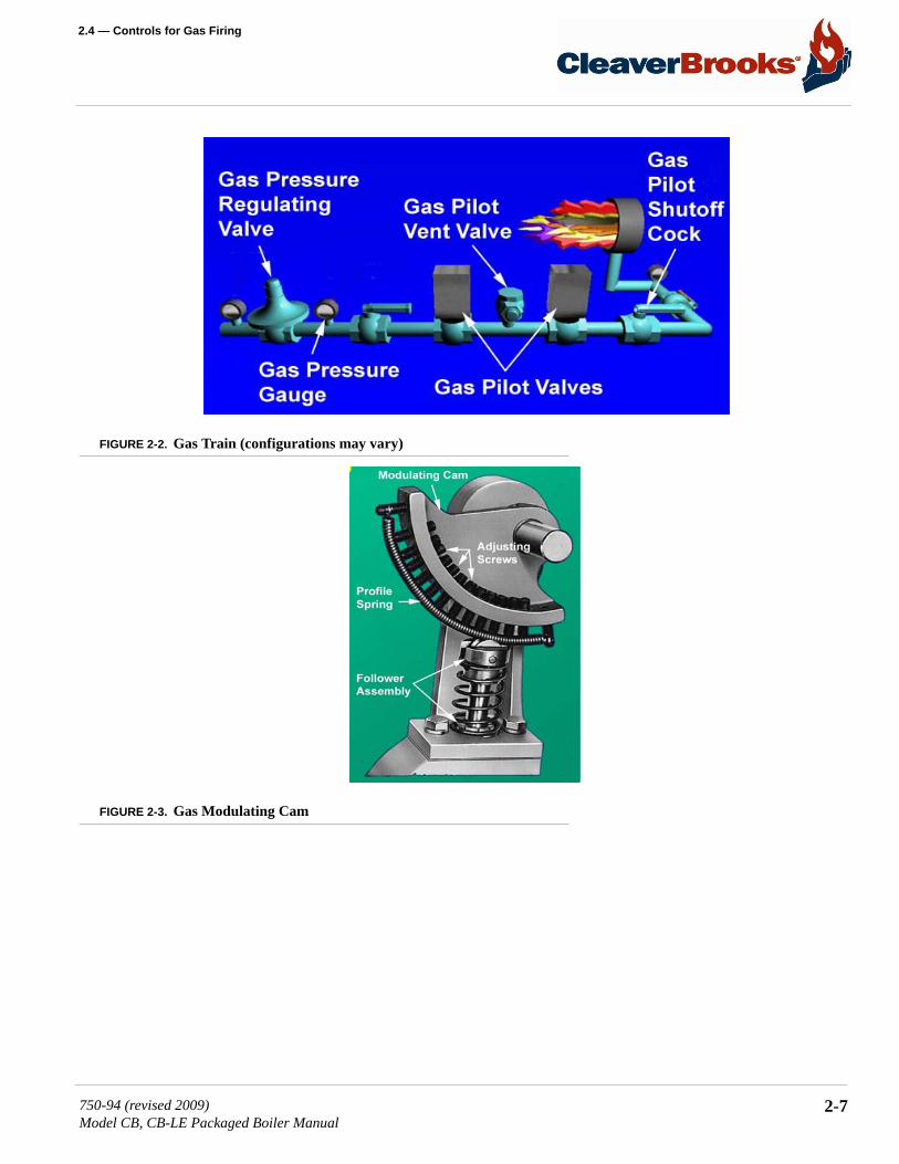
Gas Modulating Cam An assembly, consisting of a quadrant, a series of adjustable allen-head screws, and a contour spring, provided for adjustment of gas input at any point in the modulating range.
Main Gas Cock For manually opening and closing the main fuel gas supply downstream of the main gas line pressure regulator. A sec-ond shutoff cock, downstream of the main gas valve(s), is installed to provide a means of shutting off the gas line whenever a test is made for leakage across the main gas valve.
Butterfly Gas Valve The pivoted disc in the valve is actuated by connecting link-age from the gas modulating cam to regulate the rate of gas flow to the burner.
Main Gas Valves Electrically actuated shutoff valves that open simultane-ously to admit gas to the burner. The downstream valve is equipped with a “proof of closure” switch that is connected into the pre-ignition interlock circuit.
Main Gas Vent Valve A normally open solenoid valve installed between the two main gas valves to vent gas to the atmosphere should any be present in the main gas line when the gas valves are de-energized. The vent valve closes when the gas valves are energized.
Low Gas Pressure Switch A pressure actuated switch that is closed whenever main gas line pressure is above a preselected pressure. Should the pressure drop below the setting, the switch contacts open a circuit causing the main gas valve(s) to close, or prevent the burner from starting. The switch is usually equipped with a device that must be manually reset after being tripped.
High Gas Pressure Switch A pressure actuated switch that is closed whenever main gas line pressure is below a preselected pressure. Should the pressure rise above the setting, the switch contacts will open a circuit causing the main gas valve(s) to close, or pre-vent the burner from starting. The switch is usually equipped with a device that must be manually reset after being tripped.
Leakage Connection The body of the gas valve has a plugged opening that is used whenever it is necessary to conduct a test for possible leakage across the closed valve.
Component Description
2-6 750-94 (revised 2009)Model CB, CB-LE Packaged Boiler Manual
2.4 — Controls for Gas Firing
FIGURE 2-2. Gas Train (configurations may vary)
FIGURE 2-3. Gas Modulating Cam
750-94 (revised 2009)Model CB, CB-LE Packaged Boiler Manual
2-7

Burner Operation and Control
2.5 — Controls Common to Oil-Fired Boilers The following items are applicable to all oil-fired or gas and oil-fired boilers. Additional controls for No. 6 oil are listed in section 2.9 — Automatic Ignition.
FIGURE 2-4. Front of Burner Drawer.
Component Description
Oil Drawer Switch Opens the limit circuit if oil drawer burner gun is not latched in the forward position required for burning oil.
Atomizing Air Proving Switch Pressure actuated switch whose contacts are closed when sufficient atomizing air pressure from the air pump is pres-ent for oil firing. Oil valve(s) will not open, or will not remain open, unless switch contacts are closed.
Atomizing Air Pressure Gauge Indicates the atomizing air pressure at the burner gun.Oil Solenoid Valve Opens when energized through contacts in the program-
mer and allows fuel oil flow from the oil metering valve to the burner nozzle. A light oil fired burner uses two valves operating simultaneously.
2-8 750-94 (revised 2009)Model CB, CB-LE Packaged Boiler Manual
2.5 — Controls Common to Oil-Fired Boilers
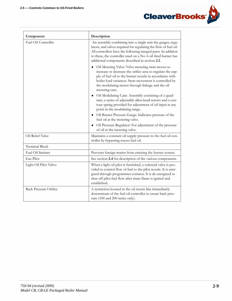
Fuel Oil Controller An assembly combining into a single unit the gauges, regu-lators, and valves required for regulating the flow of fuel oil. All controllers have the following integral parts. In addition to these, the controller used on a No. 6 oil fired burner has additional components described in section 2.1.
• Oil Metering Valve: Valve metering stem moves to increase or decrease the orifice area to regulate the sup-ply of fuel oil to the burner nozzle in accordance with boiler load variances. Stem movement is controlled by the modulating motor through linkage and the oil metering cam.
• Oil Modulating Cam: Assembly consisting of a quad-rant, a series of adjustable allen-head screws and a con-tour spring provided for adjustment of oil input at any point in the modulating range.
• Oil Burner Pressure Gauge: Indicates pressure of the fuel oil at the metering valve.
• Oil Pressure Regulator: For adjustment of the pressure of oil at the metering valve.
Oil Relief Valve Maintains a constant oil supply pressure to the fuel oil con-troller by bypassing excess fuel oil.
Terminal BlockFuel Oil Strainer Prevents foreign matter from entering the burner system.Gas Pilot See section 2.4 for description of the various components.Light Oil Pilot Valve: When a light oil pilot is furnished, a solenoid valve is pro-
vided to control flow of fuel to the pilot nozzle. It is ener-gized through programmer contacts. It is de-energized to shut off pilot fuel flow after main flame is ignited and established.
Back Pressure Orifice A restriction located in the oil return line immediately downstream of the fuel oil controller to create back pres-sure (100 and 200 series only).
Component Description
750-94 (revised 2009)Model CB, CB-LE Packaged Boiler Manual
2-9

Burner Operation and Control
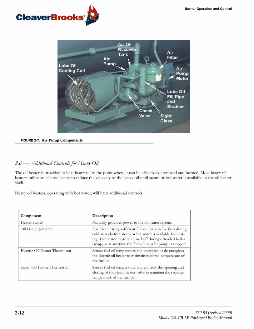
Air Pump Module Assembly Provides the compressed air required to atomize the fuel oil for proper combustion. It is started automatically by the programmer’s sequence. Components include:
• Air Pump Motor: Drives the air pump and an air cool-ing fan. The motor is started and stopped simultane-ously with the forced draft fan motor.
• Air Pump: Provides air for atomization of the fuel oil.• Air Filter: The filter cleans the air supply prior to enter-
ing the air pump.• Check Valve: Prevents lubricating oil and compressed
air from surging back through the pump and air filter when the pump stops.
• Air-Oil Receiver Tank: Holds a supply of oil for lubri-cating the air pump. The receiver tank also separates lube oil from the atomizing air before delivery to the nozzle.
• Lube Oil Level Sight Glass: Indicates the level of lubri-cating oil in the air-oil receiver tank.
• Lube Oil Cooling Coil: Cools the lubricating oil before it enters the air pump. A fan driven by the air pump motor circulates cooling air over the coil.
• Lube Oil Fill Pipe and Strainer: Used when adding oil to the air-oil receiver tank.
Low Oil Pressure Switch (optional) Switch contacts open when the fuel oil pressure drops below selected pressure. Switch will interrupt the limit cir-cuit upon loss of sufficient fuel oil pressure for correct combustion.
Fuel Oil Pump Transfers fuel oil from the storage tank and delivers it under pressure to the burner system.
Component Description
2-10 750-94 (revised 2009)Model CB, CB-LE Packaged Boiler Manual

2.5 — Controls Common to Oil-Fired Boilers
FIGURE 2-5. Oil Control Valve Assembly - Light Oil
FIGURE 2-6. Oil Control Valve Assembly - Heavy Oil
750-94 (revised 2009)Model CB, CB-LE Packaged Boiler Manual
2-11
Burner Operation and Control
FIGURE 2-7. Air Pump Components
2.6 — Additional Controls for Heavy OilThe oil heater is provided to heat heavy oil to the point where it can be effectively atomized and burned. Most heavy oil heaters utilize an electric heater to reduce the viscosity of the heavy oil until steam or hot water is available to the oil heater shell.
Heavy oil heaters, operating with hot water, will have additional controls.
Component Description
Heater Switch Manually provides power to the oil heater system.Oil Heater (electric) Used for heating sufficient fuel oil for low-fire flow during
cold starts before steam or hot water is available for heat-ing. The heater must be turned off during extended boiler lay-up, or at any time the fuel oil transfer pump is stopped.
Electric Oil Heater Thermostat Senses fuel oil temperature and energizes or de-energizes the electric oil heater to maintain required temperature of the fuel oil.
Steam Oil Heater Thermostat Senses fuel oil temperature and controls the opening and closing of the steam heater valve to maintain the required temperature of the fuel oil.
2-12 750-94 (revised 2009)Model CB, CB-LE Packaged Boiler Manual

2.6 — Additional Controls for Heavy Oil
Oil Heater Shell (steam/hot water) Heats fuel oil through medium of steam or hot water. Elec-tric heater is housed in the steam heater, but is housed sep-arately on a hot water heater. Steam oil heaters on 15 psi boilers operate at boiler pressure. Steam oil heaters fur-nished on high pressure boilers are to be operated at less than 15 psi. Operation is accomplished with a steam pres-sure regulator valve.
Oil Return Excess oil returned to the heavy oil supply tank.Oil Inlet From Supply Tank Heavy oil inlet from the supply tank.Steam Heater Check Valve Prevents oil contamination of the waterside of pressure ves-
sel should any leakage occur in the oil heater. Steam Trap Drains condensate and prevents loss of steam from the
steam oil heater. Condensate must be piped to a safe point of discharge.
Check Valve (steam heater discharge) Prevents air entry during shutdown periods when cooling action may create vacuum within steam heater.
Steam Heater Pressure Regulator Adjust to provide reduced (usually less than 15 psi) steam pressure to the heater to properly maintain the required fuel oil temperature. The regulator and the pressure gauge are not furnished on 15 psi units.
Steam Heater Solenoid Valve A normally open solenoid valve opened by the steam oil heater thermostat to allow flow of steam to the steam heater to maintain temperature of fuel oil.
Steam Pressure Gauge Indicates steam pressure entering the heater.Oil Relief Valve allows release of excessive pressure to the return side of the
oil line piped to the tank.Low Oil Temperature Switch Thermostatic switch that prevents burner from starting, or
stops burner firing if fuel oil temperature is lower than required for oil burner operation.
Oil Supply Pressure Gauge Indicates fuel oil pressure in the oil heater and supply pres-sure to the fuel oil controller’s pressure regulator.
Component Description
750-94 (revised 2009)Model CB, CB-LE Packaged Boiler Manual
2-13

Burner Operation and Control
FIGURE 2-8. Oil Heating Assembly (Steam)
In addition to the components of the fuel oil controller identified in section 2.5, the following are used with a heavy oil fired burner.
Component Description
High Oil Temperature Switch (optional) Switch contacts open when fuel oil temperature raises above a selected temperature. Switch will interrupt the limit circuit in the event fuel oil temperature rises above the selected point.
Hot Water Oil Heater Thermostat Used on a hot water boiler to sense fuel oil temperature and control the starting and stopping of the booster water pump.
Booster Water Pump Started and stopped by the hot water thermostat to regulate the flow of hot water through the hot water oil heater to maintain temperature of fuel oil.
Fuel Oil Thermometer Indicates temperature of fuel oil being supplied to the fuel oil controller.
Back Pressure Valve For adjustment of oil pressure on the downstream side of the metering valve. Also regulates rate and return oil flow.
Oil Return Pressure Gauge Indicates oil pressure on the return side of the fuel oil con-troller.
Manual Bypass Valve Provided as a timer saver in establishing oil flow. When open, it permits circulation of oil through the supply and return lines. The valve MUST be closed prior to initial light off.
2-14 750-94 (revised 2009)Model CB, CB-LE Packaged Boiler Manual

2.7 — Controls for Combination Burners Only
2.7 — Controls for Combination Burners OnlyBurners equipped to burn either oil or gas include equipment for each fuel. The Gas-Oil Selector Switch engages the appro-priate interlocks and controls for gas or oil operation. Chapter 4 details the required mechanical functions of each fuel sys-tem.
2.8 — Combustion AirAir for combustion of fuel (referred to as “secondary” air) is furnished by the forced draft fan mounted in the boiler head. In operation, air pressure is built up in the entire head and is forced through a diffuser plate for a thorough mixture with the fuel for proper combustion. The supply of secondary air to the burner is gov-erned by automatically throttling the output of the fan by regulating the rotary air damper. The damper provides the proper amount of air for correct ratio of air to fuel for efficient combustion at all firing rates.
FIGURE 2-9. Secondary Air Flow Diagram
Orifice Oil Control Valve Valve may be opened prior to startup to aid in establishing fuel oil flow through the controller. The valve MUST be closed prior to initial light off. Its disc has an orifice to per-mit a continuous circulation of hot fuel oil through the con-troller.
Air Purge Valve Solenoid valve opens simultaneously with closing of oil solenoid valve at burner shutdown, allowing compressed air to purge oil from the burner nozzle and adjacent piping. The oil is burned by the diminishing flame, which continues burning for approximately 4 seconds after the oil solenoid valve closes.
Air Purge Orifice Nozzle Limits purging air to proper quantity for expelling unburned oil at normal delivery rate.
Air Purge Orifice Nozzle Filter Filters the purging air of any particles that might plug the air purge orifice nozzle.
Air Purge Check Valve Valve check prevents fuel oil from entering the atomizing air line.
Air Purge Relay When energized, control operation of air purge valve.
Component Description
750-94 (revised 2009)Model CB, CB-LE Packaged Boiler Manual
2-15

Burner Operation and Control
2.9 — Automatic IgnitionOil or gas burners are ignited by an interrupted type pilot. The pilot flame is ignited automatically by an electric spark.
The series 100 burner usually is equipped with a pilot fired with light oil fuel. All other burners are equipped with a gas burning pilot. In the case of a combination burner, the gas pilot is used to ignite either the main gas flame or the oil flame. Either pilot serves the same function. (The term “pilot” is used interchangeably.)
At the beginning of the ignition cycle, and governed by the program relay, the pilot solenoid valve and ignition transformer are simultaneously energized.
The ignition transformer supplies high voltage current for the igniting spark. A gas pilot has a single electrode and a spark arcs between the tip of the electrode and the wall of the tube surrounding it. A light oil pilot has two electrodes and the arc is between their tips. The pilot solenoid valve and the transformer are de-energized after main flame is ignited and estab-lished.
Fuel for the gas pilot is supplied from the utility’s main, or from a tank (bottle) supply. Secondary air flows into and mixes with the pilot gas stream to provide an adequate flame.
Insurance regulations may require two gas pilot solenoid valves with a normally open vent valve between them. The vent valve closes when the gas pilot valves open, and opens when the gas pilot valves shut to vent gas, should any be present in the pilot line during the de-energized period of the gas pilot valves.
Fuel for a light-oil pilot is provided from the line that supplies oil under pressure for the main flame. A solenoid actuated valve controls flow of oil to the pilot nozzle. The valve is energized simultaneously with the ignition transformer at the beginning of the ignition cycle and is de-energized after main flame is ignited and established.
2.10 — Atomizing AirAir for atomizing the fuel oil (referred to as “primary” air) is pumped by the air pump into the air-oil receiver tank and deliv-ered under pressure through a manifold block to the oil burner nozzle.
The atomizing air mixes with the fuel oil just prior to the oil leaving the nozzle.
Atomizing air pressure is indicated by the air pressure gauge on the burner gun.
Air pressure from the pump also forces sufficient oil from the tank to the pump bearings to lubricate them and also to pro-vide a seal and lubrication for the pump vanes. As a result, the air delivered to the tank contains some lube oil, however, most of it is recovered through baffles and filters in the tank before the air passes to the burner.
Some of the primary air is also used to assist the oil pressure regulators of the fuel oil controller. Further explanation is given in chapter 5.
2-16 750-94 (revised 2009)Model CB, CB-LE Packaged Boiler Manual

2.11 — Oil Fuel Flow: Light Oil
2.11 — Oil Fuel Flow: Light OilFuel oil is delivered into the system by a supply pump which delivers part of its discharge to the oil burner. Excess oil is returned to the oil storage tank through the fuel oil relief valve and oil return line. Normally the pump operates only while the burner is in operation, although a positioning switch is often provided so that either continuous or automatic pump operation can be obtained (See Figure 2-10).
The oil flows through a fuel oil strainer to prevent any foreign material from flowing through the control valves and nozzle. The fuel oil controller contains in a single unit, a metering valve, a regulator, and a gauge required to regulate the pressure and flow of oil to the burner. The adjustable regulator controls the pressure. To assist in the regulation, back pressure is cre-ated by an orifice nozzle located in the oil return line immediately downstream of the fuel oil controller.
The programming relay energizes or de-energizes the solenoid oil valves to permit or cut off oil flow to the burner. Two valves, operating simultaneously, are used. The valves are closed when de-energized. They cannot be opened (energized) unless the combustion air proving switch and the atomizing air proving switch are closed. The two switches are satisfied, respectively, by sufficient combustion air pressure from the forced draft fan and pressurized air from the air pump.
The oil flow to the burner is controlled by the movement of the metering stem in the oil metering valve, which varies the flow to meet load demands. The metering valve and the air damper are controlled simultaneously at all times by the modu-lating motor to proportion combustion air and fuel for changes in load demand.
750-94 (revised 2009)Model CB, CB-LE Packaged Boiler Manual
2-17

Burner Operation and Control
FIGURE 2-10. Light Oil Flow Diagram
2.12 — Oil Fuel Flow: Heavy Oil Fuel oil is delivered into the system by the fuel oil supply pump which delivers part of its discharge to the oil heater. The remainder of the fuel oil returns to the oil storage tank through a fuel oil relief valve and oil return line (see Figure 2-11).
The combination electric and steam oil preheater is controlled by thermostats. The electric oil heater thermostat energizes the electric heater, which is provided to supply heated oil on cold starts. The steam heater thermostat controls operation of the steam solenoid valve to permit a flow of steam to the heater when steam is available.
2-18 750-94 (revised 2009)Model CB, CB-LE Packaged Boiler Manual
2.12 — Oil Fuel Flow: Heavy Oil
A hot water boiler is equipped to heat the oil with hot water from the boiler, unless other preheating equipment is utilized. The electric heater, which is housed separately, is sized to provide heated oil on a cold start. The hot water thermostat con-trols the operation of a pump that supplies hot water to the oil heater when hot water is available.
The heated oil flows through a fuel oil strainer to prevent any foreign matter from entering the control valves and nozzle.
The fuel oil controller contains, in a single unit, the necessary valves, regulators and gauges to regulate the pressure and flow of oil to the burner.
The program relay energizes or de-energizes the solenoid oil valve to permit or cut off oil flow to the burner. The oil sole-noid is closed when de-energized. It cannot be opened (energized) unless the combustion air proving switch, the atomizing air proving switch, and the low oil temperature and any pressure switches are closed. They are satisfied, respectively, by suf-ficient combustion air pressure from the forced draft fan, pressurized air from the air pump, and sufficient oil temperature and pressure.
Oil flow to the burner is controlled by the movement of the metering stem of the oil metering valve, which varies the flow to meet load demands. The metering valve and the air damper are controlled simultaneously at all times by the modulating motor to proportion combustion air and fuel for changes in load demand.
Oil is purged from the burner gun upon each burner shutdown. The air purge solenoid valve opens as the fuel valve closes, diverting atomizing air through the oil line. The air assures a clean nozzle and line for subsequent restart.
750-94 (revised 2009)Model CB, CB-LE Packaged Boiler Manual
2-19

Burner Operation and Control
FIGURE 2-11. No. 6 Heavy Oil Flow Diagram (Steam-Electric Heater)
2.13 — Gas Fuel FlowMetered gas from the utility flows through the pressure regulator at a reduced pressure suitable to burner requirements, through the main gas shutoff cock, main gas valve(s), and modulating butterfly gas valve to the non-premix orifice-type burner.
The main gas valve is of the normally closed type, and is opened (energized) in proper sequence by the programming relay.
2-20 750-94 (revised 2009)Model CB, CB-LE Packaged Boiler Manual
2.14 — Modulating Firing
The butterfly gas valve modulates the flow of gas from low through high fire settings. The position of the butterfly valve disc is governed by the gas modulating cam. The butterfly gas valve, and the air control damper are controlled simultane-ously by the modulating motor to proportion combustion air and fuel for changes in load demand.
The gas flow rate required for rated burner input depends upon the heating value (Btu/cubic foot) of the gas supplied. The gas pressure regulator adjusts the gas pressure (flow rate) to the entrance of the gas train. The regulator is not always sup-plied with the burner, but may be provided by others.
The main gas valves cannot be energized (opened) unless the combustion air proving switch is closed to indicate a sufficient supply of combustion air. The low gas pressure and high gas pressure switches must be closed to prove sufficient, but not excessive, gas fuel pressure.
2.14 — Modulating FiringThe modulating motor, through a linkage arrangement, controls the air damper and the butterfly gas valve, or the oil meter-ing valve, to maintain a constant air/fuel ratio throughout the firing range.
During burner operation, the motor is controlled by a modulating pressure control on a steam boiler, or by a modulating temperature control on a hot water boiler. A manually operated potentiometer is provided to permit positioning of the motor at the desired burner firing rate. The potentiometer is used primarily for initial or subsequent checking and setting of fuel input. Normal operation should be with the manual-automatic switch in the “automatic” position and under the con-trol of the modulating control.
The modulating motor (commonly called a damper motor) is reversible. It has an internal limit switch that restricts shaft rotation to 90º. During normal operation the motor will move in either direction or stop at any position within the range.
The motor potentiometer is electrically connected to a matching potentiometer in the modulating control. Changing steam pressure or water temperature alters the electrical resistance of the modulating controller potentiometer. The change in resistance compels an integral balancing relay to start, stop, or reverse the motor rotation. Rotation in either direction con-tinues until the resistance ratio of the two potentiometers is equal.
When the resistance ratio is equal, the motor stops in a position that allows the proper fuel and combustion air flow to meet operating demands.
A feature designed into the circuitry maintains the modulating motor in the low-fire position during ignition and keeps it there until the main flame is established. A low-fire switch, integral to the motor, is actuated by the rotation of the motor. The switch must be closed to establish that the damper and fuel metering valves are in the low-fire position before the pro-grammer commences into the ignition period. During this time, neither the manual flame control nor the modulating con-trol have any control over the damper motor, regardless of their setting.
An optionally equipped boiler uses a second integral switch to establish that the motor has driven the damper to an open position during the pre-purge period. The second integral switch closes, as high fire position is approached, to complete an internal circuit in the programmer to allow continuation of the programming cycle.
750-94 (revised 2009)Model CB, CB-LE Packaged Boiler Manual
2-21

Burner Operation and Control
2-22 750-94 (revised 2009)Model CB, CB-LE Packaged Boiler Manual

CHAPTER 3 Waterside Care and Requirements
3.1 — OverviewThe operator should be familiar with this chapter before attempting to place the unit into operation.
Although it is of prime importance, the subject of water supply and treatment cannot adequately be covered in this manual. For specific information or assistance with your water treatment requirements, contact your Cleaver-Brooks service and parts representative.
Feedwater equipment should be checked and ready for use. Be sure that all valves, piping, boiler feed pumps, and receivers are installed in accordance with prevailing codes and practices.
Water requirements for both steam and hot water boilers are essential to boiler life and length of service. It is vital care be taken in placing the pressure vessel into initial service. The waterside of new boilers and new or remodeled steam or hot water systems may contain oil, grease, or other foreign matter. A method of boiling out the vessels to remove the accumula-tions is described later in this chapter.
Boilers, as a part of a hot water system, require proper water circulation. The system must be operated as intended by its designer in order to avoid thermal shock or severe, possibly damaging, stresses from occurring to the pressure vessel.
3.2 — Water Requirements: Hot Water Boiler
3.2.1 — Air Removal
The hot water outlet includes a dip tube which extends 2 to 3 inches into the boiler. The dip tube reduces the possibility of air, which may be trapped at the top of the shell, from entering into the system. Oxygen or air released in the boiler will col-lect or be trapped at the top of the boiler shell.
The air vent tapping on the top center line of the boiler should be piped into the expansion or compression tank. Air trapped at the top of the boiler will find its way out of the boiler through the tapping.
NOTE: This manual only covers boilers using water. Glycol solutions have different operating requirements, circulation rates, temperatures, etc.
750-94 (revised 2009)Model CB, CB-LE Packaged Boiler Manual
3-1
Waterside Care and Requirements
3.2.1.1 — Minimum Water Temperature
The minimum recommended boiler water temperature is 170º F. When water temperatures lower than 170º F are used, the combustion gasses are reduced in temperature to a point where water vapor condenses, causing corrosion in the boiler and possible breeching.
Condensation is more severe on a unit that operates intermittently and which is greatly oversized for the actual load. Con-densation can be minimized by maintaining the boiler water temperatures above 170º F.
A temperature of 170º F is also recommended in order to provide a sufficient “temperature head” when No. 6 fuel oil is to be heated to the proper atomizing temperature by the boiler water in a safety-type oil preheater. (The electric preheater on the boiler must provide additional heat to the oil if boiler water temperature is not maintained above 200º F.
3.2.1.2 — Rapid Replacement of Boiler Water
The system layout and controls should be arranged to prevent the possibility of pumping large quantities of cold water into a hot boiler, which will cause shock or thermal stresses. Water temperature in a boiler of 200º F or 240º F cannot be com-pletely replaced with 80º F water in a few minutes time without causing thermal stress. The same fact applies to periods of normal operation, as well as during initial startup.
When individual zone circulating pumps are used, it is recommended that they be kept running, even though the hear users do not require hot water. The relief device or bypass valve will thus allow continuous circulation through the boiler and can help prevent rapid replacement of boiler water with cold zone water.
3.2.1.3 — Continuous Flow Through the Boiler
The system should be piped and the controls arranged to allow water circulation through the boiler under all operating con-ditions. The operation of three-way valves and system controls should be checked to be sure that the boiler will not be bypassed. Constant circulation through the boiler eliminates the possibility of stratification within the unit and results in more even water temperatures to the system.
A rule of thumb of 3/4 to 1 gpm per boiler horsepower can be used to determine the minimum continuous flow rate through the boiler under all operating conditions. The operator should determine that a flow of water exists through the boiler before initial firing or refiring after the boiler has been drained.
3.2.2 — Water Circulation
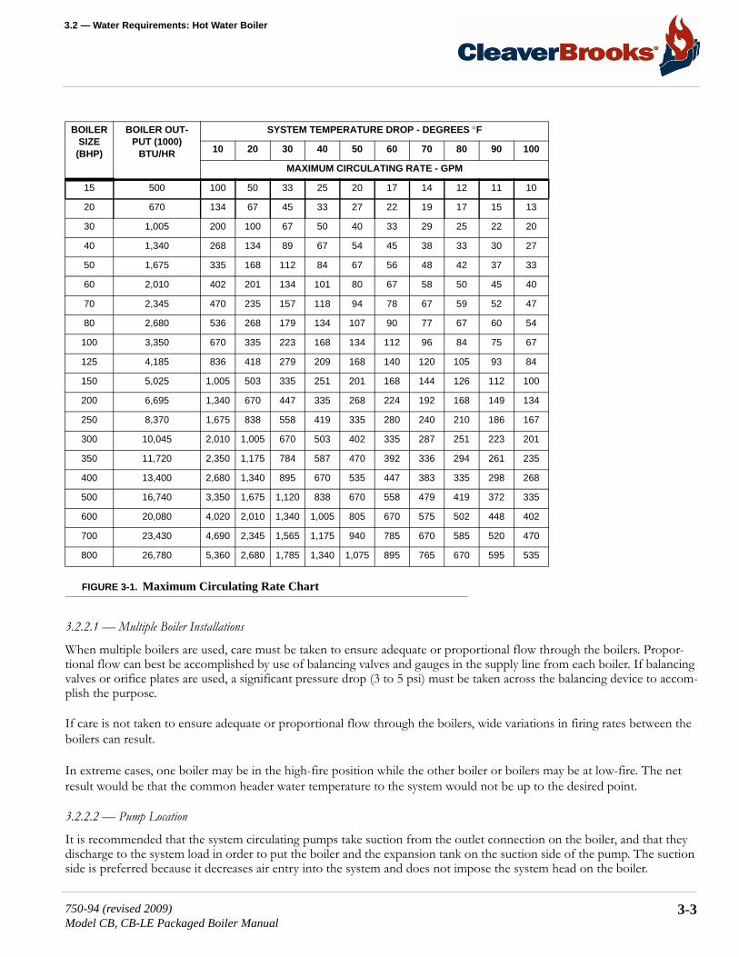
The following chart shows the maximum gpm circulation rate of boiler water in relation to full boiler output and system temperature drop.
NOTE: If the operating water temperature going to the system must be lower than 170º F, the operating boiler water tem-perature should be a minimum of 170º F (200º F if used to preheat No. 6 oil) and mixing valves should be used to avoid damage to the equipment.
NOTE: The circulating pumps should be interlocked with the burner so that the burner cannot operate unless the circulat-ing pump is running in order to avoid damage to the equipment.
3-2 750-94 (revised 2009)Model CB, CB-LE Packaged Boiler Manual
3.2 — Water Requirements: Hot Water Boiler
FIGURE 3-1. Maximum Circulating Rate Chart
3.2.2.1 — Multiple Boiler Installations
When multiple boilers are used, care must be taken to ensure adequate or proportional flow through the boilers. Propor-tional flow can best be accomplished by use of balancing valves and gauges in the supply line from each boiler. If balancing valves or orifice plates are used, a significant pressure drop (3 to 5 psi) must be taken across the balancing device to accom-plish the purpose.
If care is not taken to ensure adequate or proportional flow through the boilers, wide variations in firing rates between the boilers can result.
In extreme cases, one boiler may be in the high-fire position while the other boiler or boilers may be at low-fire. The net result would be that the common header water temperature to the system would not be up to the desired point.
3.2.2.2 — Pump Location
It is recommended that the system circulating pumps take suction from the outlet connection on the boiler, and that they discharge to the system load in order to put the boiler and the expansion tank on the suction side of the pump. The suction side is preferred because it decreases air entry into the system and does not impose the system head on the boiler.
BOILER SIZE
(BHP)
BOILER OUT-PUT (1000)
BTU/HR
SYSTEM TEMPERATURE DROP - DEGREES °F
10 20 30 40 50 60 70 80 90 100
MAXIMUM CIRCULATING RATE - GPM
15 500 100 50 33 25 20 17 14 12 11 10
20 670 134 67 45 33 27 22 19 17 15 13
30 1,005 200 100 67 50 40 33 29 25 22 20
40 1,340 268 134 89 67 54 45 38 33 30 27
50 1,675 335 168 112 84 67 56 48 42 37 33
60 2,010 402 201 134 101 80 67 58 50 45 40
70 2,345 470 235 157 118 94 78 67 59 52 47
80 2,680 536 268 179 134 107 90 77 67 60 54
100 3,350 670 335 223 168 134 112 96 84 75 67
125 4,185 836 418 279 209 168 140 120 105 93 84
150 5,025 1,005 503 335 251 201 168 144 126 112 100
200 6,695 1,340 670 447 335 268 224 192 168 149 134
250 8,370 1,675 838 558 419 335 280 240 210 186 167
300 10,045 2,010 1,005 670 503 402 335 287 251 223 201
350 11,720 2,350 1,175 784 587 470 392 336 294 261 235
400 13,400 2,680 1,340 895 670 535 447 383 335 298 268
500 16,740 3,350 1,675 1,120 838 670 558 479 419 372 335
600 20,080 4,020 2,010 1,340 1,005 805 670 575 502 448 402
700 23,430 4,690 2,345 1,565 1,175 940 785 670 585 520 470
800 26,780 5,360 2,680 1,785 1,340 1,075 895 765 670 595 535
750-94 (revised 2009)Model CB, CB-LE Packaged Boiler Manual
3-3
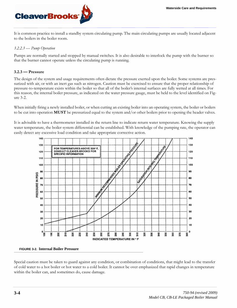
Waterside Care and Requirements
It is common practice to install a standby system circulating pump. The main circulating pumps are usually located adjacent to the boilers in the boiler room.
3.2.2.3 — Pump Operation
Pumps are normally started and stopped by manual switches. It is also desirable to interlock the pump with the burner so that the burner cannot operate unless the circulating pump is running.
3.2.3 — Pressure
The design of the system and usage requirements often dictate the pressure exerted upon the boiler. Some systems are pres-surized with air, or with an inert gas such as nitrogen. Caution must be exercised to ensure that the proper relationship of pressure-to-temperature exists within the boiler so that all of the boiler’s internal surfaces are fully wetted at all times. For this reason, the internal boiler pressure, as indicated on the water pressure gauge, must be held to the level identified on Fig-ure 3-2.
When initially firing a newly installed boiler, or when cutting an existing boiler into an operating system, the boiler or boilers to be cut into operation MUST be pressurized equal to the system and/or other boilers prior to opening the header valves.
It is advisable to have a thermometer installed in the return line to indicate return water temperature. Knowing the supply water temperature, the boiler system differential can be established. With knowledge of the pumping rate, the operator can easily detect any excessive load condition and take appropriate corrective action.
FIGURE 3-2. Internal Boiler Pressure
Special caution must be taken to guard against any condition, or combination of conditions, that might lead to the transfer of cold water to a hot boiler or hot water to a cold boiler. It cannot be over emphasized that rapid changes in temperature within the boiler can, and sometimes do, cause damage.
3-4 750-94 (revised 2009)Model CB, CB-LE Packaged Boiler Manual
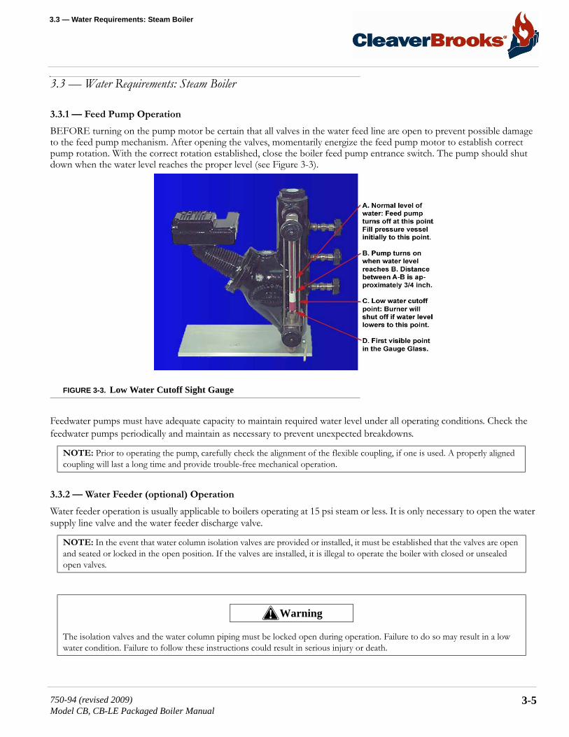
3.3 — Water Requirements: Steam Boiler
3.3 — Water Requirements: Steam Boiler
3.3.1 — Feed Pump Operation
BEFORE turning on the pump motor be certain that all valves in the water feed line are open to prevent possible damage to the feed pump mechanism. After opening the valves, momentarily energize the feed pump motor to establish correct pump rotation. With the correct rotation established, close the boiler feed pump entrance switch. The pump should shut down when the water level reaches the proper level (see Figure 3-3).
FIGURE 3-3. Low Water Cutoff Sight Gauge
Feedwater pumps must have adequate capacity to maintain required water level under all operating conditions. Check the feedwater pumps periodically and maintain as necessary to prevent unexpected breakdowns.
3.3.2 — Water Feeder (optional) Operation
Water feeder operation is usually applicable to boilers operating at 15 psi steam or less. It is only necessary to open the water supply line valve and the water feeder discharge valve.
NOTE: Prior to operating the pump, carefully check the alignment of the flexible coupling, if one is used. A properly aligned coupling will last a long time and provide trouble-free mechanical operation.
NOTE: In the event that water column isolation valves are provided or installed, it must be established that the valves are open and seated or locked in the open position. If the valves are installed, it is illegal to operate the boiler with closed or unsealed open valves.
The isolation valves and the water column piping must be locked open during operation. Failure to do so may result in a low water condition. Failure to follow these instructions could result in serious injury or death.
! Warning
750-94 (revised 2009)Model CB, CB-LE Packaged Boiler Manual
3-5

Waterside Care and Requirements
3.4 — Water TreatmentProperly treated boiler feed water, coupled with good engineering and operating practices, lead to maximum effectiveness and long trouble-free life of pressure vessels, at the lowest operating cost. Contact your local Cleaver-Brooks authorized representative for information on how to prevent the presence of unwanted solids and corrosive gasses.
Objectives of water treatment in general are:
• Prevent hard scale deposits or soft sludge deposits, which reduce heat transfer and can lead to overheated metal and costly downtime and repairs.
• eliminate corrosive gasses in the supply or boiler water.• Prevent intercrystalline cracking or caustic embrittlement of boiler metal.• Prevent carryover and foaming.
Accomplishment of the above objectives generally requires proper feedwater treatment before and after introduction of the water into the boiler. The selection of pre-treatment processes depends upon the water source, its chemical characteristics, amount of makeup water needed, plant operating practices, etc. Treating methods include filtering, softening de-mineraliz-ing, deaerating, and preheating. After-treatment involves chemical treatment of the boiler water.
Because of the variables involved, no single boiler compound can be considered a “cure-all” nor is it advisable to experi-ment with homemade treating methods. Sound recommendations and their employment should be augmented by a peri-odic analysis of the feedwater, boiler water, and condensate.
The internal or waterside surfaces of the pressure vessel should be inspected with enough frequency to determine the pres-ence of any contamination, accumulations of foreign matter, corrosion, and/or pitting. If any of the conditions are detected, contact your local Cleaver-Brooks authorized representative for advice on corrective action.
A properly sized water meter should be installed in the raw water make-up line in order to accurately determine the amount of raw water admitted to the boiler (steam or hot water) and to aid in maintaining proper waterside conditions.
3.5 — Cleaning
3.5.1 — Hot Water and Steam Piping
Steam and water piping systems connected to the boiler may contain oil, grease, or foreign matter. The impurities must be removed in order to prevent damage to pressure vessel heating surfaces. On a steam system, the condensate should be wasted until tests show the elimination of undesirable impurities. During the periods that condensate is wasted, attention must be given to the treatment of the raw water used as make-up so that an accumulation of unwanted materials or corro-sion does not occur. For more information, contact your local Cleaver-Brooks authorized representative.
On a hot water system, chemical cleaning is generally necessary and the entire system should be drained after treatment. Consult your local Cleaver-Brooks authorized representative for recommendations, cleaning compounds, and application procedures.
3-6 750-94 (revised 2009)Model CB, CB-LE Packaged Boiler Manual
3.6 — Boil-Out of a New Unit
3.5.2 — Pressure Vessel
The waterside of the pressure vessel must be kept clean from grease, sludge, and foreign material. Such deposits, if present, will shorten the life of the pressure vessel, will interfere with efficient operation and functioning of control of safety devices, and quite possibly cause unnecessary and expensive re-work, repairs, and downtime.
The installation and operating conditions that the boiler will be subjected to should be considered and cleaning of the water-side of the pressure vessel should be provided during the course of initial start-up.
The pressure vessel and the steam and return lines or hot water piping represent, in effect, a closed system. Although the steam and return (condensate) lines or the hot water piping system may have been previously cleaned, it is possible that:
• Cleaning has been inadequate.• Partial or total old system is involved.• Conditions may prevent adequate cleaning of piping.
The pressure vessel waterside should be inspected on a periodic basis. An inspection will reveal true internal conditions and serve as a check against conditions indicated by chemical analysis of the boiler water. Inspection should be made three months after initial starting and at regular 6-, 9-, or 12-month intervals thereafter. The frequency of further periodic inspec-tions will depend upon the internal conditions found.
If any unwanted conditions are observed, contact you local Cleaver-Brooks authorized representative for recommendations.
Any sludge, mud, or sediment found will need to be flushed out. If excessive mud or sludge is noticed during the blow-down, the scheduling or frequency of blowdown may need to be revised. The need for periodic draining or washout will also be indicated.
Any oil or grease present on the heating surfaces should be removed promptly by a boil-out with an alkaline detergent solu-tion.
3.6 — Boil-Out of a New UnitThe internal surfaces of a newly installed boiler may have oil, grease, or other protective coatings used in manufacturing. Such coatings must be removed because they lower the heat transfer rate and could cause over-heating of a tube. Before boiling out procedures may begin, the burner should be ready for firing. The operator must be familiar with the procedure outlined under burner operation.
NOTE: Temperature of initial fill of water for hydrostatic tests, boil-out, or for normal operation should be as stated in the ASME Boiler Code.
Use of a suitable face mask, goggles, rubber gloves, and protective garments is strongly recommended when handling or mixing caustic chemicals. Do not permit the dry material or the concentrated solution to come in contact with skin or clothing. Failure to follow these instructions could result in serious injury or death.
! Warning
750-94 (revised 2009)Model CB, CB-LE Packaged Boiler Manual
3-7

Waterside Care and Requirements
Your local Cleaver-Brooks authorized representative will be able to recommend a cleaning or boil-out procedure. In the event such service is unavailable or is yet unscheduled, the following information may be of assistance.
Several chemicals are suitable for boil-out. One combination often used is soda ash (sodium carbonate) and caustic soda (sodium hydroxide) at the rate of 3 to 5 pounds each per 1,000 pounds of water, along with a small amount of laundry detergent added as a wetting agent.
The suggested general procedure for cleaning a boiler is (refer to Figure 3-4 to determine water capacity):
1. Have sufficient cleaning material on hand to complete the job.2. When dissolving chemicals:
a) warm water should be put into a suitable containerb) slowly introduce the dry chemical into the water, stirring at all times until completely dissolvedc) add the chemical slowly and in small amounts to prevent excessive heat and turbulence
3. An overflow pipe should be attached to one of the top boiler openings and routed to a safe point of discharge. A relief or safety valve tapping is usually used.
4. Water relief valves and steam safety valves must be removed before adding the boil-out solution so that neither it nor the grease which it may carry will contaminate the valves. Use care in removing and reinstalling the valves. (Refer to Chapter 8, section 8.-13 for valve installation instructions.)
5. All valves in the piping leading to or from the system must be closed to prevent the cleaning solution form getting into the system.
6. Fill the pressure vessel with clean water until the top of the tubes is covered. Add the cleaning solution and then fill to the top. The temperature of the water used in the initial fill should be at ambient temperature.
7. The boiler should then be fired intermittently at a low rate sufficient to hold solution just at the boiling point. Boil the water for at least five hours. Do not produce steam pressure.
FIGURE 3-4. Water Capacity and Weights
8. Allow a small amount of fresh water to enter the boiler to create a slight overflow that will carry off surface impurities.9. Continue the boil and overflow process until the water clears. shut the burner down.10. Let the boiler cool to 120º F or less.
11. Remove handhole plates and wash the waterside surfaces thoroughly using a high pressure water stream.
Generator Sizes
Water - Gallons Water - Weight
Normal Flooded Normal Flooded
CB-LE 400 HP 1777 2402 14810 20015CB-LE 500 HP 1914 2796 15950 23300CB-LE 600 HP 2312 3391 19270 28260CB-LE 700 HP 2760 4003 23000 33360CB-LE 800 HP 2760 4003 23000 33360
Be sure to drain the hot water to a safe point of discharge to avoid scalding. Failure to follow these instructions could result in serious injury or death.
! Warning
3-8 750-94 (revised 2009)Model CB, CB-LE Packaged Boiler Manual
3.7 — Washing Out
12. Inspect the surfaces. If they are not clean, repeat the boil-out.13. After closing the handholes and reinstalling the safety or relief valves, fill the boiler and fire it until the water is heated to
at least 180º F to drive off any dissolved gasses, which might otherwise corrode the metal.
The above procedure may be omitted in the case of a unit previously used or known to be internally clean. However, con-sideration must be given to the possibility of contaminating materials entering the boiler from the system.
On a steam system, the condensate should be wasted until tests show the elimination of undesirable impurities. During the period that condensate is wasted, be sure make-up water is treated to prevent an accumulation of unwanted materials or cor-rosion.
On a hot water system, chemical cleaning is generally necessary and the entire system should be drained after treatment. Consult your local Cleaver-Brooks authorized representative for recommendations, cleaning compounds, and application procedures.
3.7 — Washing Out
3.7.1 — Hot Water Boiler
In theory, a hot water system and boiler that has been initially cleaned, filled with raw water (and water treated), and with no make-up water added, will require no further cleaning or treatment. However, since the system (new or old) can allow entrance of air and unnoticed or undetected leakage of water, introductions of raw water make-up or air may lead to pitting, corrosion, and formation of sludge, sediment, scale, etc. on the pressure vessel waterside.
If the operator is absolutely certain that the system is tight, then an annual waterside inspection may be sufficient. However, if there is any doubt, the pressure vessel waterside should be inspected no later than three months after initially placing the boiler into operation, and periodically thereafter as indicated by conditions observed during inspections.
3.7.2 — Steam Boiler
No later than three months after initially placing the boiler into operation and starting service, and thereafter as conditions warrant, the pressure vessel should be drained after being properly cooled to near ambient temperature. Handhole covers should be removed and waterside surfaces should be inspected for corrosion, pitting, or formation of deposits.
3.7.3 — Flushing of Pressure Vessel Interior
Upon completion of the inspection, the pressure vessel interior should be flushed out, as required, with a high pressure hose. If deposits are not fully removed by flushing, a consultation may be required with your local Cleaver-Brooks autho-rized representative. In extreme cases, it may be necessary to resort to acid cleaning. Professional advice is recommended if acid cleaning is required.
The inspections will indicate the effectiveness of the feedwater treatment. The effectiveness of treatment, the water condi-tions, and the amount of fresh water make-up required are all factors to be considered in establishing frequency of future pressure vessel washouts. Contact your local Cleaver-Brooks authorized representative for more information.
750-94 (revised 2009)Model CB, CB-LE Packaged Boiler Manual
3-9

Waterside Care and Requirements
3.8 — Blowdown: Steam BoilerBoiler water blowdown is the removal of some of the concentrated water from the pressure vessel and its replacement with feedwater so that the lowering of the concentration of solids in the boiler water occurs.
Solids are brought in by the feedwater even though the water is treated prior to use through external processes that are designed to remove unwanted substances which contribute to scale and deposit formations. However, none of the pro-cesses can remove all substances. Regardless of their high efficiency, some solids will be present in the boiler feedwater.
Solids become less soluble in the high temperature of the boiler water and tend to accumulate on heating surfaces. There-fore, blowdown and internal chemical treatment are required to prevent the solids from forming harmful scale and sludge.
Scale has a low heat transfer value and acts as an insulation barrier. Scale retards heat transfer, which not only results in lower operating efficiency, and consequently higher fuel consumption, but more importantly, can cause overheating of boiler metal. Overheating of boiler metal can result in tube failures or other pressure vessel metal damage and lead to boiler down-time and costly repairs.
Scale is caused primarily be calcium and magnesium salts, silica, and oil. Any calcium and magnesium salts in the boiler water are generally precipitated by the use of sodium phosphate, along with organic materials, to maintain the precipitates or “sludge” in a fluid form. The solids such as sodium salts and suspended dirt don not readily form scale. But as the boiler water boils off as relatively pure steam, the remaining water is thickened with the solids. If the concentration is permitted to accumulate, foaming and priming will occur and the sludge can cause harmful deposits that bring about overheating of the metal.
The lowering or removal of the concentration requires the use of boiler water blowdown. The two principal types of blow-down are intermittent manual blowdown and continuous blowdown.
3.8.1 — Intermittent Manual Blowdown
Manual or sludge blowdown is necessary for the operation of the boiler regardless of whether or not continuous blowdown is employed.
The blowdown tappings are located at the bottom or lowest part of the boiler in order to lower the dissolved solids in the pressure vessel water, and to remove a portion of the sludge that accumulates in the lower part of the vessel.
Equipment generally consists of a quick opening valve and a shutoff valve. The valves and necessary piping are not nor-mally furnished with the boiler, but supplied by others. All piping must be to a safe point of discharge. Piping must be prop-erly supported and free to expand.
3.8.2 — Continuous Blowdown
Continuous blowdown is used in conjunction with a surface blow-off tapping (furnished on 60” diameter and larger units) and is the continuous removal of concentrated water.
The surface blow-off opening, when furnished, is on the top center line of the pressure vessel. It is provided with an inter-nal collecting pipe terminating slightly below the working water level for the purpose of skimming surface sediment, oil, or other impurities from the surface of the pressure vessel water.
A controlled-orifice valve is used to allow a continual, yet controlled, flow of concentrated water.
3-10 750-94 (revised 2009)Model CB, CB-LE Packaged Boiler Manual

3.8 — Blowdown: Steam Boiler
Periodic adjustments are made to the valve setting to increase or decrease the amount of blowdown in accordance with the test analysis.
The flow control valve and piping are generally provided by others. All piping must be to a safe point of discharge.
3.8.3 — Frequency of Manual Blowdown
When continuous blowdown is utilized, manual blowdown is primarily used to remove suspended solids or sludge. The con-tinuous blowdown removes sediment and oil from the surface of the water along with a prescribed amount of dissolved sol-ids.
When surface or continuous blowdown is not utilized, manual blowdown is used to control the dissolved or suspended sol-ids in addition to the sludge.
In practice, the valve(s) of the bottom blowdown are opened periodically in accordance with an operating schedule and/or chemical control tests. From the standpoint of control, economy and results, frequent short blows are preferred to infre-quent lengthy blows. The length and frequency of the blowdown is particularly important when the suspended solids con-tent of the water is high. With the use of frequent short blows a more uniform concentration of the pressure vessel water is maintained.
In cases where the feedwater is exceptionally pure, or where there is a high percentage of return condensate, blowdown may be employed less frequently since less sludge accumulates in the pressure vessel. When dissolved and/or suspended solids approach or exceed predetermined limits, manual blowdown to lower the concentrations is required.
It is generally recommended that a steam boiler be blown down at least once in every eight-hour period, but frequency may vary depending upon water and operating conditions. The blowdown amounts and schedule should be recommended by your local Cleaver-Brooks authorized representative.
A hot water boiler does not normally include openings for surface blowdown and bottom blowdown since blowdowns are seldom practiced. The need remains to be alert to system water losses and corresponding amount of raw water make-up. A water meter is recommended for water make-up lines.
3.8.4 — Manual Blowdown Procedure
Blowdown is most effective at a point when the generation of steam is at the lowest rate and feedwater input is also low, thus providing a minimum dilution of the boiler water with low concentration feedwater.
1. Be sure the blow-off piping and tank, if used, are in proper operating condition. Discharge vents should be clear of obstruction, and the waste should be piped to a point of safe discharge.Most blow-off lines are provided with two valves, generally a quick opening valve nearest the boiler and slow opening globe type valve downstream. Valves will vary depending upon pressure involved and make or manufacturer. If seatless valves are installed, follow the manufacturer’s recommendations. If a quick opening valve and globe type of slow opening valve are in combination, the former is normally opened first and closed last with blow down accomplished with the globe or slow opening valve.
750-94 (revised 2009)Model CB, CB-LE Packaged Boiler Manual
3-11

Waterside Care and Requirements
2. When opening the second or downstream valve, crack it slightly to allow the lines to warm, then continue opening slowly.
The length of each blow should be determined by actual water analysis. Lowering the water in the gauge glass approxi-mately 1/2” is often acceptable as a guide to adequate blow. However, lowering the water 1/2” should not be interpreted as a rule since water analysis procedures should prevail. If the glass cannot be viewed by the party operating the valve, another operator should watch the glass and direct the valve operator.
3. Close the downstream (slow opening) valve first and as fast as possible.4. Close the valve next to the boiler.5. Slightly crack the downstream valve and then close it tightly.
Under not circumstances should a blow-off valve be left open and the operator should never leave until the blowdown operation is completed and the valves are closed.
3.9 — Periodic InspectionInsurance regulations or local laws will require a periodic inspection of the pressure vessel by an authorized inspector. Suf-ficient notice is generally given to permit removal of the boiler from service and preparation for inspection.
When shutting down the boiler, the load should be reduced gradually and the pressure vessel cooled at a rate that avoids damaging temperature differential that can cause harmful stresses. Vessels should not normally be drained until all pressure is relieved - to prevent uneven contraction and temperature differentials that can cause expanded tubes to leak. Draining the unit too quickly may cause the baking of deposits that may be present on the heating surfaces. Some heat, however, may be desirable to dry out the interior of the boiler.
If the internal inspection is being made at the request of an authorized inspector, it is well to ask the inspector observe the conditions prior to cleaning or flushing of waterside surfaces.
Be certain that a supply of manhole and handhole gaskets is available, along with any other gaskets or items needed to place the unit back into operation after inspection.
Have available information on the boiler design, dimensions, generating capacity, operating pressure or temperature, time in service, defects found previously, and any repairs or modifications. Also have available for reference records of previous inspections.
Be prepared to perform any testing required by the inspector including a hydrostatic test.
Do not pump the lever action valve open and closed, as water hammer is apt to break the valve bodies or pipe fittings. Fail-ure to follow these instructions could cause damage to the equipment.
To avoid the hazard of electrical shock, we recommend the use of a low voltage flashlight during an internal inspection. Preferably, inspectors should work in pairs. Failure to follow these instructions could result in serious injury or death.
! Caution
! Warning
3-12 750-94 (revised 2009)Model CB, CB-LE Packaged Boiler Manual

3.10 — Preparation for Extended Lay-Up
After proper cooling and draining of the vessel, flush out the waterside with a high pressure water hose. Remove any scale or deposits from the waterside surfaces and check for internal or external corrosion and leakage.
The fireside surface should also be thoroughly cleaned so that metal surfaces, welds, joints, tube ends, fittings and any previ-ous repairs can be readily checked.
Be sure that steam valves, and valves to expansion tank (hot water), feedwater valves, blow-off valves, all fuel valves, and electrical switches are shut off prior to opening handholes, manhole, and front or rear doors. Adequately vent the pressure vessel prior to entry.
Clean out the low-water cutoff piping, the water level controls and cross-connecting pipes. Replace the water gauge glass and clean out the water cocks. Also check and clean the drain and the blowdown valves and piping.
Check all water and steam piping and valves for leaks, wear, corrosion, and other damage. Replace or repair as required.
3.10 — Preparation for Extended Lay-UpMany boilers used for heating or seasonal loads or for standby service may have extended periods of non-use. Special atten-tion must be given to idle boilers so that neither waterside nor fireside surfaces are allowed to deteriorate from corrosion.
Too many conditions exist to lay down definite rules. There are two methods of storage: wet or dry. Your local Cleaver-Brooks authorized representative can recommend the better method depending upon circumstances in the particular instal-lation.
Whichever method is used, common sense dictates a periodic recheck of fireside and waterside conditions during lay-up to allow variations from the above methods for special area or job-site conditions.
Swing open the boiler head at the stack end of the unit to prevent flow of warm, moist air through the boiler tubes.
Although pollution control regulations may continue to limit the permissible sulphur content of fuel oils, care must be taken to avoid corrosion problems that sulphur can cause, especially in a boiler that is seasonally shut down. Dormant periods, and even frequent shutdowns, expose the fireside surfaces to condensation below the dew point during cooling. Moisture and any sulphur residue can form an acid solution. Under certain conditions, and especially in areas with high humidity, the corrosive effect of the acid will be serious enough to eat through or severely damage boiler tubes or other metal heating sur-faces during the time that a boiler is out of service.
The condition does not generally occur during normal firing operation, because the high temperature of operation vapor-izes any condensation. However, proper boiler operation must be maintained, especially with a hot water boiler, to prevent the flue gasses from falling below the dew point.
At the start of lay-up, thoroughly clean the fireside by removing any soot or other products of combustion from the tubes, tube sheets, and other fireside surfaces. Brushing will generally suffice. Sweep away or vacuum any accumulation. The fire-side surfaces may be flushed with water. However, all moisture must be eliminated after flushing and the surface dried by blowing air or applying some form of heat. It is good practice to protect the cleaned surfaces by coating them with an anti-corrosive material to prevent rust.
750-94 (revised 2009)Model CB, CB-LE Packaged Boiler Manual
3-13
Waterside Care and Requirements
T prevent condensation from forming in the control cabinet, keep the control circuit energized. For extended lay-up peri-ods, especially where high humidity or large swings in ambient temperature occur, the control should be removed and stored in a dry atmosphere.
Dry storage is generally employed when the boiler will be out of service for a significant period of time, or where freezing temperatures may exist. In the dry storage method the boiler must be thoroughly dried because any moisture would cause corrosion. Both fireside and waterside surfaces must be cleaned of all scale, deposits, soot, etc. Steps must be taken to elim-inate moisture by placing moisture-absorbing materials such as quick lime (at 2 pounds for 3 cubic feet of volume) or silica gel (at 5 pounds for 30 cubic feet of volume) on trays inside the vessel. Fireside surfaces may be coated with an anti-corro-sive material, or grease or tar paint. Refractories should be brushed clean and wash-coated. All openings to the pressure ves-sel, such as manhole and handholes, should be shut tightly. Feedwater and steam valves should be closed. Damper and vents should be closed to prevent air from reaching fireside surfaces. Periodic inspection should be made and absorption materi-als renewed.
Wet storage is generally used for a boiler held in stand-by condition or in cases where dry storage is not practical. The pos-sibility of freezing temperatures must be considered. Care must again be taken to protect metal surfaces. Variables preclude definite recommendations. However, it is suggested that the pressure vessel be drained, thoroughly cleaned internally, and re-filled to overflowing with treated water. If deaerated water is not available, the unit should be fired to boil the water for a short period of time. Additional chemicals may be suggested by your local Cleaver-Brooks authorized representative to minimize corrosion. Internal water pressure should be maintained at greater than atmospheric pressure. Nitrogen is often used to pressurize the vessel. Fireside surfaces must be thoroughly cleaned and the refractory should be wash-coated.
3-14 750-94 (revised 2009)Model CB, CB-LE Packaged Boiler Manual

CHAPTER 4 Sequence of Operation
4.1 — OverviewChapter 4 outlines the electrical sequencing of various controls through the pre-purge, ignition, run, and shutdown cycles of the burner.
The program relay establishes the sequence of operation and directs the operation of all other controls and components to provide an overall operating sequence.
A. The burner and control system are in starting condition when the following conditions exist:
• Boiler water is up to the correct level, closing the low-water cutoff switch.• The low-water light (panel) is off.• The operating limit pressure control (steam boiler) or the operating limit temperature control (hot water boiler) and high
limit pressure or temperature control are below their cutoff setting.• All applicable limits are correct for burner operation.• The load demand light glows.
B. All entrance switches are closed and power is present at the line terminals of:
• Blower motor starter• Air compressor motor starter (if provided)• Oil heater relay (if provided)• Oil pump motor starter (if provided)
The sequences do not attempt to correlate the action of the fuel supply system or feedwater system except for the interlock controls that directly relate to the action of the program relay. Chapters 6 and 7 contain operating instructions and specific information on setting and adjusting the controls.
NOTE: The make or model of the program relay provided will vary depending upon job specifications. The following sequence applies regardless of the make or model. Please refer to the Wiring Diagram (WD) prepared by Cleaver-Brooks for your specific installation.
750-94 (revised 2009)Model CB, CB-LE Packaged Boiler Manual
4-1
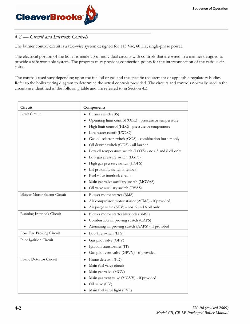
Sequence of Operation
4.2 — Circuit and Interlock ControlsThe burner control circuit is a two-wire system designed for 115 Vac, 60 Hz, single-phase power.
The electrical portion of the boiler is made up of individual circuits with controls that are wired in a manner designed to provide a safe workable system. The program relay provides connection points for the interconnection of the various cir-cuits.
The controls used vary depending upon the fuel oil or gas and the specific requirement of applicable regulatory bodies. Refer to the boiler wiring diagram to determine the actual controls provided. The circuits and controls normally used in the circuits are identified in the following table and are referred to in Section 4.3.
Circuit Components
Limit Circuit • Burner switch (BS)• Operating limit control (OLC) - pressure or temperature• High limit control (HLC) - pressure or temperature• Low-water cutoff (LWCO)• Gas-oil selector switch (GOS) - combination burner only• Oil drawer switch (ODS) - oil burner• Low oil temperature switch (LOTS) - nos. 5 and 6 oil only• Low gas pressure switch (LGPS)• High gas pressure switch (HGPS)• LE proximity switch interlock• Fuel valve interlock circuit• Main gas valve auxiliary switch (MGVAS)• Oil valve auxiliary switch (OVAS)
Blower Motor Starter Circuit • Blower motor starter (BMS)• Air compressor motor starter (ACMS) - if provided• Air purge valve (APV) - nos. 5 and 6 oil only
Running Interlock Circuit • Blower motor starter interlock (BMSI)• Combustion air proving switch (CAPS)• Atomizing air proving switch (AAPS) - if provided
Low Fire Proving Circuit • Low fire switch (LFS)
Pilot Ignition Circuit • Gas pilot valve (GPV)• Ignition transformer (IT)• Gas pilot vent valve (GPVV) - if provided
Flame Detector Circuit • Flame detector (FD)• Main fuel valve circuit• Main gas valve (MGV)• Main gas vent valve (MGVV) - if provided• Oil valve (OV)• Main fuel valve light (FVL)
4-2 750-94 (revised 2009)Model CB, CB-LE Packaged Boiler Manual

4.3 — Sequence of Operation: Oil or Gas
To comply with requirements of insurance underwriters such as Factory Mutual (FM), Industrial Risk Insurers (IRI), or oth-ers, additional interlock devices may be used.
4.3 — Sequence of Operation: Oil or GasOn a combination fuel unit, the gas/oil switch must be set for the proper fuel.
The following sequence occurs with power present at the program relay (PR) input terminals and with all other operating conditions satisfied.
4.3.1 — Pre-Purge Cycle
When the burner switch (BS) is turned “on,” and controls wired in the “limit” and “fuel valve interlock” circuits are closed and no flame signal is present, the “blower motor start circuit” is powered energizing the blower motor starter (BMS). The load demand light (LDL) turns on. When firing oil, the air compressor motor starter (ACMS - if provided) is also powered. the air purge valve (APV - nos. 5 and 6 oil only) remains de-energized.
At the same time, the program relay signals the modulating damper motor (MDM) to open the air damper. The damper begins to open and drives to its full open or high fire position. Opening the damper motor allows a flow of purging air through the boiler prior to the ignition cycle.
On certain boilers the circuitry will include a high fire switch (HFS). The purpose of the switch is to prove that the modu-lating damper motor (MDM) has driven the damper to the open position during the pre-purge cycle. In this instance, the “high fire proving circuit” is utilized.
The controls wired into the “running interlock circuit” must be closed within 10 seconds after the start sequence. In the event any of the controls are not closed at this time, or if they subsequently open, the program relay will go into a safety shutdown.
At the completion of the high fire purge period, the program relay signals the modulating damper motor (MDM) to drive the air damper to its low fire position.
To assure that the system is in low fire position prior to ignition, the low fire switch (LFS) must be closed to complete the “low fire proving circuit.” The sequence will stop and hold until the modulating damper motor (MDM) has returned to the
Firing Rate Circuit • Damper motor transformer (DMT)• Modulating damper motor (MDM)• Manual-automatic switch (MAS)• Manual flame control (MFC)• Modulating control (MC)
High Fire Proving Circuit • High fire switch (HFS)
Running Interlock and Limit Circuit • Low oil pressure switch (LOPS)• High oil pressure switch (HOPS)• High oil temperature switch (HOTS)• Auxiliary low-water cutoff (ALWCO)
Circuit Components
750-94 (revised 2009)Model CB, CB-LE Packaged Boiler Manual
4-3

Sequence of Operation
low fire position and the contacts of the low fire switch (LFS) are closed. Once the low fire switch is closed, the sequence is allowed to continue.
4.3.2 — Ignition Cycle
The ignition transformer (IT) and gas pilot valve (GPV) are energized from the appropriate pilot ignition terminal.
The pilot flame must be established and proven by the flame detector (FD) within a 10 second period in order for the igni-tion cycle to continue. If for any reason this does not happen, the system will shut down and safety lockout will occur.
With a proven pilot, the main fuel valve(s) (OV or MGV) is energized and the main fuel valve light (FVL) in the panel is lighted. The main flame is ignited and the trial period for proving the main flame begins. It lasts 10 seconds for light oil and natural gas, and 15 seconds for heavy oil. At the end of the proving period, if the flame detector still detects main flame, the ignition transformer and pilot valve are de-energized and pilot flame is extinguished.
4.3.3 — Run Cycle
With main flame established, the program relay releases the modulating damper motor (MDM) from its low fire position to control by either the manual flame control (MFC) or the modulating control (MC), depending upon the position of the manual-automatic switch (MAS). This allows operation in ranges above low fire.
With the manual-automatic switch (MAS) set at automatic, subsequent modulated firing will be at the command of the modulating control (MC), which governs the position of the modulating damper motor (MDM). The air damper and fuel valves are actuated by the motor through a linkage and cam assembly to provide modulated firing rates.
NOTE: The ignition trial cannot be started if flame or a flame simulating condition is sensed during the pre-purge period. A safety shutdown will occur if flame is sensed at this time.
NOTE: An oil-fired burner may be equipped with an oil pilot rather than a gas pilot. The ignition sequence of both is identical.
NOTE: Depending upon the requirements of the regulatory body, insurer, or fuel being burned, either the 10 or 15 sec-ond pilot ignition terminal may be used. Both provide the same function but differ in time interval allowed for proving main flame ignition. Refer to the boiler wiring diagram.
NOTE: If the main flame does not light, or stay lit, the fuel valve will close. The safety switch will trip to lock out the con-trol. Refer to flame loss sequence (see Section 4.4) for description of action.
The cause for loss of flame or any other unusual condition should be investigated and corrected before attempting to restart. Failure to follow these instructions could result in serious injury or death.
! Warning
4-4 750-94 (revised 2009)Model CB, CB-LE Packaged Boiler Manual

4.4 — Flame Loss Sequence
The burner starting cycle is now complete. The LDL and FVL lights on the panel remain lit. Demand firing continues as required by load conditions.
4.3.4 — Burner Shutdown: Post Purge
The burner will fire until steam pressure or water temperature in excess of demand is generated. With modulated firing, the modulating damper motor (MDM) should return to the low fire position before the operating limit control (OLC) opens. When the limit control circuit is opened, the following sequence occurs:
1. The main fuel valve circuit is de-energized, causing the main fuel valve (MGV or OV) to close. 2. The flame is extinguished. 3. The control panel lights (LDL and FVL) are turned off.4. The blower motor continues to run to force air through the boiler for the post purge period.5. On a No. 6 oil burner, the air purge valve (APV) is powered from the blower motor start circuit via the contacts of the
air purge relay (APR) to provide an air purge of the oil nozzle. The damper motor returns to the low fire position if it is not already in that position.
6. The blower motor start circuit is de-energized at the end of the post purge cycle and the shutdown cycle is complete.
The program relay is now ready for subsequent recycling, and when steam pressure or water temperature drops to close the contacts of the operating control, the burner again goes through its normal starting and operating cycle.
4.4 — Flame Loss SequenceThe program relay will recycle automatically each time the operating control closes, or after a power failure. It will lockout following a safety shutdown caused by failure to ignite the pilot, or the main flame, or by loss of flame. Lockout will also occur if flame or flame simulating condition occurs during the pre-purge period.
The control will prevent startup or ignition if limit circuit controls or fuel valve interlocks are open. The control will lock out upon any abnormal condition affecting air supervisory controls wired in the running interlock circuit.
4.4.1 — No Pilot Flame
The pilot flame must be ignited and proven within a 10-second period after the ignition cycle begins. If not proven within this period, the main fuel valve circuit will not be powered and the fuel valve(s) will not be energized. The ignition circuit is immediately de-energized and the pilot valve closes, the reset switch lights and lockout occurs immediately.
NOTE: Normal operation of the burner should be with the switch in the manual-automatic position and under the direction of the modulating control. The manual position is provided for initial adjustment of the burner over the entire firing range. When a shutdown occurs while operating in the manual position at other than low fire, the damper will not be in a closed posi-tion, thus allowing more air than desired to flow through the boiler. Excess air flow subjects the pressure vessel metal and refractory to undesirable conditions. The effectiveness of nozzle purging is lost on a No. 6 oil burner.
The lockout switch must be manually reset following a safety shutdown. The cause for loss of flame or any unusual condition should be investigated and corrected before attempting to restart. Failure to follow these instructions could cause damage to the equipment.
! Caution
750-94 (revised 2009)Model CB, CB-LE Packaged Boiler Manual
4-5

Sequence of Operation
The blower motor will continue to operate. The flame failure light and the alarm bell (optional) are energized 10 seconds later.
The blower motor will be de-energized. The lockout switch must be manually reset before operation can be resumed. (Refer to the previous caution notice.)
4.4.2 — Pilot But No Main Flame
When the pilot flame is proven, the main fuel valve circuit is energized. Depending upon the length of the trial-for-ignition period, the pilot flame will be extinguished 10 or 15 seconds later. The flame detecting circuit will respond to de-energize the main fuel valve circuit within 2 to 4 seconds to stop the flow of fuel. The reset switch lights and lockout occurs immedi-ately. The blower motor will continue to operate.
The flame failure light and alarm bell (optional) are energized 10 seconds later.
The blower motor will be de-energized. The lockout switch must be manually reset before operation can be resumed. (Refer to the previous caution notice.)
4.4.3 — Loss of Flame
If a flame outage occurs during normal operation and/or the flame is no longer sensed by the detector, the flame relay will trip within 2 to 4 seconds to de-energize the fuel valve circuit and shut off the fuel flow. The reset switch lights and lockout occurs immediately. The blower motor continues operation. The flame failure light and alarm bell (optional) are energized 10 seconds later.
The blower motor will be de-energized. The lockout switch must be manually reset before operation can be resumed. (Refer to the previous caution notice.)
If the burner will not start, or upon a safety lockout, the troubleshooting section in the operating manual and the technical bulletin should be referred to for assistance in pinpointing problems that may not be readily apparent.
The program relay has the capability to self-diagnose and to display a code or message that indicates the failure condition. Refer to the control bulletin for specifics and suggested remedies. Familiarity with the program relay and other controls in the system can be obtained by studying the contents of the manual and bulletin.
Knowledge of the system and its controls will make troubleshooting much easier. Costly down time or delays can be pre-vented by systematic checks of the actual operation against the normal sequence to determine the stage at which perfor-mance deviates from normal. Following a routine may possibly eliminate overlooking an obvious condition, often one that is relatively simple to correct.
Remember, a safety device, for the most part, is doing its job when it shuts down or refuses to operate. NEVER attempt to circumvent any of the safety features.
Preventive maintenance and scheduled inspection of all components should be followed. Periodic checking of the relay is recommended to see that a safety lockout will occur under conditions of failure to ignite either pilot or main flame, or from loss of flame.
4-6 750-94 (revised 2009)Model CB, CB-LE Packaged Boiler Manual
CHAPTER 5 Starting and Operating Instructions
5.1 — OverviewThe instructions in Chapter 5 are all based upon installation being complete and all electrical, fuel, water, and vent stack connections are made.
The operator should be familiar with the burner, boiler, and all controls and components. To quickly locate and identify the various controls and components mentioned the following paragraphs, refer to the illustrations and the contents of Chap-ters 1, 2, and 3. Instructions for adjusting major components are given in Chapter 6 — Chapter 6 should be reviewed prior to firing. The wiring diagram should also be thoroughly reviewed, along with the firing sequence outlined in Chapter 4.
Verify supply of fuel and proper voltage. Check for blown fuses, open circuit breakers, dropped out overloads, etc. Check reset of all starters and controls having manual reset features. Check the lockout switch on the programmer and reset if nec-essary.
The boiler should be filled with water to the proper operating level using water of ambient temperature. Be sure that treated feedwater is available and use. In heating applications, the entire system should be filled and vented. Refer to Chapter 3 for water requirements. On a steam boiler, open the test valve to vent air displaced during filling. Leave the test valve open until the escape of steam is noted after the burner is operating.
It is recommended that the starting instructions be read completely until they are thoroughly understood, before attempting to operate the boiler, rather than performing each operation as it is read for the first time. Failure to follow these instructions could result in serious injury or death.
Prior to firing a boiler, be sure that discharge piping from safety valves or relief valves, and discharge piping from all blowdown and drain valves, is piped to a SAFE point of discharge, so that emission of hot water or steam cannot possibly cause injury. Fail-ure to do so could result in serious injury or death.
! Warning
! Warning
750-94 (revised 2009)Model CB, CB-LE Packaged Boiler Manual
5-1

Starting and Operating Instructions
Check all linkage for full and free movement of the damper and metering valves and cams. The check can be done by loos-ening the linkage at the damper motor connecting arm and manipulating the linkage by hand.
Check for rotation of all motors by momentarily closing the motor starter or relay. The blower impeller rotation is counter-clockwise when viewed from the front of the boiler. The air pump rotation is clockwise when viewed from its drive end.
Before operating the boiler feed pump or oil supply pump, be sure all valves in the line are open or properly positioned.
For safety reasons, perform a final pre-startup inspection, especially checking for any loose or incomplete piping or wiring or any other situations that might present a hazard.
5.2 — Control Settings: Steam and Hot WaterSee Chapter 6 for adjustment instructions for the following controls:
5.2.1 — Operating Limit Control
Inspect the operating limit control for proper setting.
• The pressure control of a steam boiler should be set slightly above the highest desired steam pressure, but at least 10% lower than the setting of the safety valve.
• The temperature control on a hot water boiler should be set slightly above the highest desired water temperature and within the limits of the pressure vessel.
5.2.2 — High Limit Control
Inspect the high limit control for proper setting.
• On a high pressure steam boiler, the control should be set approximately 10 psig above the operating limit pressure con-trol setting, if feasible, or midway between the operating limit pressure and the safety valve setting. The setting on a low pressure steam boiler may be 2 or 3 psig above the operating limit setting, but must not exceed the safety valve setting.
• On a hot water boiler, the high limit temperature control should be 5º to 10º F above the operating limit temperature control setting but within the limits of the design pressure of the pressure vessel.
5.2.3 — Modulating Control
Inspect the modulating control for proper setting. The control must be set and adjusted so that the modulating motor returns to low fire position before the operating limit control opens. It is further desirable to have its low point setting
NOTE: The pressure vessel support legs are welded to mounting skids in front and secured by bolts at the rear of the pres-sure vessel. The bolts are tightened for shipment. When the boiler is installed, and prior to initial firing, the bolts securing the rear legs to the skid must be loosened to allow for expansion and contraction caused by differences in temperature between pressure vessel and skids and to avoid damage to the equipment.
5-2 750-94 (revised 2009)Model CB, CB-LE Packaged Boiler Manual

5.3 — Gas Pilot
somewhat below the cut-in setting of the limit control so that the burner operates in low fire position for a brief period on each start rather than immediately driving to a high fire position.
5.2.4 — Low-Water Cutoff and Pump Control
Inspect the low-water cutoff and pump control as well as the auxiliary low-water cutoff (if equipped with this optional device). Check for freedom of float movement. Float movement can be verified by observing the level of water in the gauge glass when the water supply has been cut off either by the stopping of the feed pump or by the closing of a valve, and the restarting of the pump or opening of the valve when water is drained from the pressure vessel. The importance of proper functioning of low-water controls cannot be over-emphasized. Be sure that the control and the piping are level.
5.2.5 — Additional Considerations
The settings of controls relating to fuel, either oil or gas, are covered in subsequent sections.
In the event the boiler is equipped with optional control devices not listed here, be certain to ascertain that their settings are correct. If additional information is required, see your local Cleaver-Brooks authorized representative.
On initial startup or whenever the boiler is placed into operation from a “cold” start, the manual-automatic selector switch should be set at “manual” and the manual flame control set at “close.” After the boiler is in operation and thoroughly warmed, the selector switch should be turned to “automatic,” so that the burner firing rate may be controlled by the modu-lating control in accordance with load demands.
Close all power entrance switches (supplied by others).
5.3 — Gas PilotThe gas pilot should be checked for satisfactory performance prior to initial firing. Follow the pilot flame adjustment instructions given in Chapter 6.
On initial starting attempts, several efforts might be required to fully bleed the pilot line. While checking pilot adjustment, observe whether the pilot flame is extinguished promptly when the burner switch is opened. A lingering flame indicates a leaking gas pilot valve, which is a condition requiring correction before proceeding.
NOTE: The settings of all the above controls may require some readjustment after the boiler is started and running for a short period. The scale settings on the controls are relatively accurate, but are principally for use as guides. Final adjustment should be based on and agree with the reading of the steam pressure gauge or the water temperature thermometer.
750-94 (revised 2009)Model CB, CB-LE Packaged Boiler Manual
5-3

Starting and Operating Instructions
5.4 — Atomizing AirThe supply and pressure of the atomizing air on an oil-fired burner should be checked. Before starting, inspect the oil pump lube oil level. Add oil if necessary to bring the level to the midpoint or slightly higher in the sight glass. Use SAE 20 deter-gent oil of a grade mentioned in Chapter 8 and fill in accordance with instructions given there.
FIGURE 5-1. Atomizing Air Compressor
Check the oil level of the air intake strainer.
To verify air flow and pressure, place the burner run/test switch on the program relay to the “test” position. If the burner is a combination fuel burner, be sure that the gas/oil selector switch is set to “oil.” Turn the burner switch on. The burner will cycle to the low fire pre-purge position and stop there.
FIGURE 5-2. Atomizing Air Pressure Gauge
5-4 750-94 (revised 2009)Model CB, CB-LE Packaged Boiler Manual
5.5 — Firing Preparations for No. 2 Oil (Series 100 - 200)
Observe the reading on the air pressure gauge. With no oil flow, the pressure should be a minimum of 7 psi.
If there is no pressure, determine the cause and correct it before proceeding. Check for obstructions in the air inlet line, incorrect rotation (air pump rotation is clockwise), or a loose oil nozzle or other leaks. If the pressure is much higher with-out any oil flow, check for obstruction in the discharge line or at the oil nozzle.
The air pressure will increase when an oil flow exists. At low firing rate, the air pressure may rise to 12 psi or more.
After air flow has been verified, turn the burner switch off and return the run/test switch to the “run” position.
5.5 — Firing Preparations for No. 2 Oil (Series 100 - 200)Prior to initial firing, oil flow and pressure should be established and verified. Atomizing air pressure should also be estab-lished as outlined in Section 5.4. The schematic flow diagram (see Chapter 2) indicates the flow of fuel and atomizing air.
If the burner is a combination fuel model, be certain that the main gas shutoff cock is closed and set the gas/oil selector switch to “oil.” Insert the burner drawer gun into its most forward position and latch it in place.
5.5.1 — Oil Flow
1. Open all valves in the oil suction and oil return lines.2. If the oil supply tank is located above the level of the pump and flow to the pump is by gravity, then it will usually be nec-
essary to vent the suction line to allow oil to fill the line. Venting the suction line can generally be accomplished by crack-ing a union fitting, or by opening the cap of the oil strainer using care to prevent spillage of oil. Tighten the fitting or the cap as soon as oil flow appears. If the oil supply tank is below the level of the oil pump, it is MANDATORY that the suction line to the pump be com-pletely filled with oil prior to starting the pump to avoid the possibility of damage to the pump gears. Non-lubricating fluids such as kerosene should not be used for priming.
3. Prior to priming the suction line and the initial start, check to make certain that all plugs, connections, etc., have been securely tightened to prevent leaks.
4. If the fuel oil supply originates from a pressurized loop, it is assumed that the pressure of the loop will be at a minimum of 75 psi. Under these conditions, the relief valve at the terminal block should be adjusted to the point where it becomes inoperative (or removed and openings plugged). To render inoperative, turn the adjusting screw in as far as possible.
5. A standard equipped boiler has a selector switch incorporated in the oil pump motor starter. Momentarily energize the starter to check for proper pump rotation. With the rotation verified, operate the pump to determine that oil circulation exists.
6. Observe the oil burner pressure gauge for indication that flow is established. If no pressure shows on the gauge after a few moments, stop the oil pump and re-prime.
NOTE: The air pressure should not exceed 35 psi at high fire. Greater air pressure causes excessive wear of the air pump., increases lube oil usage, and can overload the motor, thus causing damage to the equipment.
NOTE: Abnormally high pressure indicated on the nozzle air pressure gauge is an indication that the burner nozzle has become clogged. In the event of clogging check the nozzle and clean as necessary.
750-94 (revised 2009)Model CB, CB-LE Packaged Boiler Manual
5-5

Starting and Operating Instructions
If the supply tank is lower than the pump, it is possible that the initial priming of the suction line, followed by operation of the pump, will not establish oil flow. This might be caused by obstruction in the suction line, excessive lift, inadequate priming, suction line leaks, etc. If oil flow is not readily established, avoid prolonged operation of the pump to minimize risk of damage to internal parts of the pump.
7. A vacuum (or a compound pressure-vacuum) gauge should be installed at the suction port of the pump and its reading observed and recorded for future guidance. If a vacuum condition exists, the reading will reveal the tightness of the sys-tem. It is advisable to maintain the vacuum reading at less than 10” Hg. A vacuum in excess of 10” Hg. may allow oil to vaporize, causing cavitation, loss of prime, and unstable firing condition.
FIGURE 5-3. No.2 Fuel Oil Control
5.5.2 — Oil Pressure
1. Oil supply pressure is regulated by adjusting the pressure relief valve at the oil terminal block. A pressure gauge should be installed in the terminal block and the relief valve adjusted to obtain a minimum reading of 75 psi when the burner is firing at maximum rate.
2. When oil is supplied from a pressurized loop to a multiple boiler installation, the relief valve in the loop should be prop-erly adjusted to provide this reading. In this circumstance, the relief valve at the terminal block should be adjusted to the point when it will be inoperative (or removed and openings plugged). To render inoperative, turn the adjusting screw in as far as possible.
3. Adjustment may also be required to the regulator on the fuel oil controller. The pressure regulating valve is equipped with tubing that directs and adds atomizing air pressure to the adjustable spring pressure. Since the air pump is not run-ning at this time, only tentative adjustment can be made. Without the air supply, adjust the fuel oil pressure regulator so that the oil burner gauge registers approximately 35 psi.
4. The pressure gauge will indicate a higher reading when the flame is present and will increase as the firing rate increases. After the burner is firing and when the air pump is running, final adjustment can be made at the fuel oil controller.
5. Final regulation of oil flow to the nozzle can be done later, if necessary, by adjusting the metering cam screws as outlined in Chapter 6.
NOTE: If oil flow is not established after a second or third priming attempt, a full investigation is required to determine the cause.
5-6 750-94 (revised 2009)Model CB, CB-LE Packaged Boiler Manual

5.6 — Firing Preparation for No. 6 Oil (Series 400 - 600)
5.5.3 — Starting
When all the conditions covered in Sections 5.1, 5.2, 5.3, 5.4, and 5.5 are assured, the burner is ready for firing. Refer to Sec-tion 5.8 for further starting and operating information.
5.6 — Firing Preparation for No. 6 Oil (Series 400 - 600)Prior to initial firing, oil flow, pressure, and temperature should be established and verified. Atomizing air pressure should also be established as outlined in Section 5.4. The schematic flow diagram (see Chapter 2) indicates the flow of fuel and atomizing air.
If the boiler is a combination fuel model, be certain that the main gas shutoff cock is closed and set the gas/oil selector switch to “oil.” Insert the burner drawer gun into its most forward position and latch it in place.
5.6.1 — Oil Flow
1. Open all valves in the oil suction and oil return lines.2. Open the bypass valve on the fuel oil controller until oil flow is established. Normally, the orifice valve is left in a closed
position. however, on cold starts, it may be opened for brief periods to aid in establishing oil flow. The bypass and orifice valves must be returned to the closed positions as soon as oil flow is established as indicated by a reading on the oil sup-ply pressure gauge. Do not at temp to set pressures while valves are open.
FIGURE 5-4. No. 6 Fuel Oil Control
3. Momentarily energize the fuel oil pump starter to check for proper pump rotation. With the rotation verified, prime the suction line strainer with oil and turn the fuel oil pump switch to the “ON” position.
4. Check the oil supply pressure gauge for indication that oil flow is established. If no pressure shows on the gauge after a few moments, stop the oil pump and re-prime. Heavy oil in the storage tank must be at a temperature to produce an oil viscosity that will allow the oil to flow through the oil pump and suction line. If oil flow is not established after several
750-94 (revised 2009)Model CB, CB-LE Packaged Boiler Manual
5-7
Starting and Operating Instructions
attempts, the conditions preventing oil flow must be determined and corrected to avoid damage to the pump’s internal mechanism.
5. A vacuum gauge should be installed in the oil suction line and its reading observed and recorded for future guidance.
5.6.2 — Oil Pressure
Oil pressure is regulated at several points. The first is at the relief valve at the oil heater. The relief valve should be set so that at maximum firing rate a minimum reading of 75 psi is obtained on the oil supply pressure gauge.
The other pressure adjustments are to the regulators on the fuel oil controller. Both the pressure regulating and the back pressure relief valves are equipped with tubing that directs and adds atomizing air pressure to the adjustable spring pressure. Since the air pump is not running at this time, only tentative adjustments can be made. Without the air supply, adjust the fuel oil pressure regulator so that the burner oil gauge registers approximately 35 psi. Adjust the back pressure relief valve so that its gauge reads about 10 psi less than the burner gauge.
After the burner is firing, further adjustments can be made, if necessary, to the valves.
The pressure gauges will indicate higher readings when a flame is present. The pressure will increase as the firing rate increases. The pressure reading on the two gauges on the controller will, despite the fluctuation, retain a nearly constant dif-ference of 10 psi.
Final regulation of oil flow to the nozzle can be done, if necessary, by adjusting the metering cam screws as outlined in Chapter 6.
5.6.3 — Oil Temperature
Suggested oil pressures at high fire operation:
1. After determining that the heater shell is filled and that fuel oil circulation exists, turn the oil heater switch to “on.”2. Adjust the electric oil heater thermostat to maintain oil temperature at approximately 200º F.
The electric heater on burners equipped for No. 6 fuel oil is sized so that it is capable of supplying heated oil at a rate no greater than that required for low fire operation and is primarily supplied for convenience on cold starts. Heating coils utilizing either steam or hot water are supplied to provide sufficient heat so that higher rates of firing can be accom-plished once steam pressure or hot water is available. In normal operation, the thermostat governing the electric heating element is kept at a lower setting than the thermostat governing admission of steam to the heater, or of hot water circu-lation, so that heating is not performed electrically except when steam or hot water is not available.
Oil Supply at the Fuel Oil Controller 75 psiOil Burner Pressure Gauge 30 - 45 psi
Before turning on the electric oil heater switch, be certain that the heater shell is filled with fuel oil and the flow is estab-lished. Failure to follow these instructions could result in equipment damage.
! Caution
5-8 750-94 (revised 2009)Model CB, CB-LE Packaged Boiler Manual

5.7 — Firing Preparations for Gas (Series 200-400-700)
3. Set the steam thermostat or the hot water thermostat to maintain an oil temperature of 220º - 230º F. The electric heater will be turned off automatically as soon as steam or hot water provides heat.
4. Close the manual bypass valve after the temperature rise on the fuel oil controller thermometer is noted. Be certain that hot oil is moving through the controller. The orifice gate valve must also be closed. If the temperature drops, open the orifice gate valve until a rise is noted, then close it.
5. Once the correct setting of the heater thermostats has been established, set the low oil temperature switch at the point approximately 30º F lower than the normal burning temperature. If the system is equipped with a high oil temperature switch, it should be set to open at 20º to 30º F higher than normal burning temperature.
5.6.4 — Starting
When all the conditions covered in Sections 5.1, 5.2, 5.3, and 5.4 are assured, the burner is ready for firing. Refer to Section 5.8 for further starting and operating information.
5.7 — Firing Preparations for Gas (Series 200-400-700)1. Prior to initial starting, check the linkage attached to the gas butterfly valve to assure that movement is free from binding.2. Verify the presence and availability of gas. On a new installation, representatives of the gas utility should be present when
gas first flows into the system to supervise purging of the new gas line, unless they have already done so.3. Determine that the pilot is operating properly, as outlined in Section 5.3.4. Determine that sufficient pressure exists at the entrance to the gas train by installing a test gauge downstream of the reg-
ulator.5. The gas pressure regulator must be adjusted to the proper pressure level. Since the regulator is generally supplied by oth-
ers, adjustment should proceed according to instructions supplied by its manufacturer.It is necessary for the operator to know the burner requirements in gas quantity and pressure. The information can gen-erally be found on the Dimension Diagram (DD) supplied by Cleaver-Brooks for the specific installation. Should the information not be readily available, consult the Cleaver-Brooks Service Department, and be prepared to provide the correct boiler serial number. Chapter 6 contains additional information along with standard gas flow and pressure requirements.
6. If the burner is a combination fuel model, set the gas/oil switch to “gas.” Withdraw the oil burner gun and latch it in its rearward (OUT) position.
FIGURE 5-5. Latch Oil Burner Gun “IN” and “OUT” Positions
NOTE: The temperatures listed are tentative. The composition of the fuel oil in a given grade can vary, necessitating a higher or lower preheating temperature. The viscosity of the oil at the nozzle should be less than 300 SSU and preferably less than 150 SSU. The actual temperature of the oil at the burner should be determined by flame appearance and good combustion based on a stack analysis. Review this chapter for additional information.
750-94 (revised 2009)Model CB, CB-LE Packaged Boiler Manual
5-9

Starting and Operating Instructions
7. On initial startup, it is recommended that the main gas shutoff cock remains closed until the programmer has cycled through pre-purge and pilot sequences. When the fuel light on the control panel comes on, observe the action of the motorized gas valve stem to determine that it opens when energized.
8. As soon as it is confirmed, turn the burner switch “OFF” and let the programmer finish its cycle.9. Check that the gas valve has closed. 10. Again, turn the burner “ON.”11. When the fuel valve light flows, slowly open the main gas cock. Main flame should ignite unless there is air present in the
line. 12. If the flame is not established within about 5 seconds, turn the burner switch “OFF” and allow the programmer to recy-
cle normally for a new lighting trial. Several efforts may be necessary to “bleed” air from the line.
13. Once the main flame is established, turn the burner switch to the “OFF” position and observe that the flame is extin-guished promptly. The flame may continue to burn for a second or two after normal shutdown due to the gas remaining downstream from the fuel valve.
14. If the flame continues to burn for a longer period or during blower motor spindown, it could indicate a main gas valve leak. Immediately turn the burner switch off and close the main gas cock.
15. Investigate and correct the cause of the valve leakage before relighting the burner.
When the conditions covered in Section 5.7 and in Sections 5.1, 5.2, and 5.3 are assured, the burner is ready for firing. Refer to Section 5.8 for further starting and operating information.
5.8 — IFGR Setup
It is recommended that the final “installed” settings be recorded for future reference. The settings should be marked on the linkage as well.
Normally, once the system has been set and adjusted, the settings should not be changed unless conditions (including boiler settings) change. In that case, it will be necessary to contact your local Cleaver-Brooks authorized representative for assis-tance.
Do not repeat unsuccessful lighting attempts without rechecking the burner and pilot adjustments. Failure to follow these instructions could result in serious injury or death.
NOTE: The burner and control system is designed to provide a “pre-purge” period of fan operation prior to establishing ignition spark and pilot flame. Do not attempt to alter the system or to take any action that might circumvent the feature.
NOTE: The main gas valve should provide a tight seal, provided nothing prevents tight closure. Foreign material may be present in either the new or renovated gas lines unless adequate care is taken in cleaning and purging.
NOTE: Initial IFGR linkage settings and adjustments must be established by a Cleaver-Brooks authorized representative. Setup of the LE option requires simultaneous consideration of air-to-fuel ratios and NOX levels. This can only be accom-plished with proper combustion emissions monitoring equipment with NOX, O2, CO, and smoke spot measuring capability.
! Warning
5-10 750-94 (revised 2009)Model CB, CB-LE Packaged Boiler Manual

5.8 — IFGR Setup
After the IFGR system is initially set up, it will start up with the boiler as an integrated boiler system. After shutdown peri-ods in which maintenance and/or adjustments have been performed on the fuel cams, fuel and air linkages, or IFGR con-trol linkages, the recommended approach to startup is as follows:
1. Set all boiler components to their initial settings as discussed in the appropriate chapters of this manual.2. Check fan impeller and motor rotation. Correct rotation is counterclockwise when viewed from the front of the boiler.3. Verify that all the IFGR components are set to the settings recorded on the Startup Report (as noted by the Cleaver-
Brooks authorized representative during original set up). Be sure that all linkages are secure.4. Start and warm the boiler as described in this manual.5. Adjust the boiler components as described in this manual to achieve proper boiler operation.
Refer to Chapter 8 for instructions on cassette removal and installation.
FIGURE 5-6. Jackshaft Linkage Settings
NOTE: The IFGR system can be equipped with either a single or dual linkage arm, depending on the number of fuels used and the NOX levels desired. All single-fueled boilers have a single drive arm. Dual-fueled boilers may or may not have a dual arm, depending on the options purchased.
750-94 (revised 2009)Model CB, CB-LE Packaged Boiler Manual
5-11

Starting and Operating Instructions
FIGURE 5-7. Overtravel Linkage Settings
FIGURE 5-8. Flange Collar and Damper Settings (Top View)
5-12 750-94 (revised 2009)Model CB, CB-LE Packaged Boiler Manual

5.9 — Startup, Operating and Shutdown: All Fuels
5.9 — Startup, Operating and Shutdown: All FuelsDepending upon the fuel being burned, the applicable previous sections in this chapter should be reviewed for preliminary instructions.
1. When firing with oil, be certain that the burner gun is in its most forward position and latched in place. When firing with gas, the burner gun should be properly withdrawn and latched in place. The fuel selector switch should be, accordingly, set to either oil or gas.
2. Set the manual-automatic switch to “manual” and turn the manual flame control to “close.”3. Turn the burner switch to “ON.” The load demand light should glow. The low-water level light should remain out, indi-
cating a safe water level in the boiler. The programmer is now sequencing. See Chapter 4 for sequence details.
4. On ignition failure, the flame failure light will glow and the blower will purge the boiler of unburned fuel vapors before stopping. After ignition failure, wait a few moments before resetting the lockout switch.
5. After main flame ignition, the burner should be set on manual control at its low-fire setting (that is, with manual flame control at “close”) until the boiler is properly warmed. Close the steam header.In the case of a steam boiler, CLOSE the test valve when the steam begins to appear.A hot water boiler must have a continuous flow of system water through the vessel during the warmup period. The entire water content of the system and boiler must be warmed prior to increasing fuel input.
6. If the flame at low-fire provides insufficient heat to reach normal operating pressure or temperature after 30 minutes, gradually increase the firing rate by turning the manual flame control in one point increments to no higher than the third cam screw. Operate at the increased fuel input rate for a period of time until an increase is noted in pressure or tempera-ture.
7. After the boiler is thoroughly warmed, turn the manual flame control to high-fire. At this point a combustion analysis should be made, with instruments, and fuel flow regulated as required. Refer to the adjustment procedures in Chapter 6. After making the high-fire adjustment, manually decrease the firing rate, stopping at each cam screw to analyze combus-tion gasses, and adjust as required.
To properly perform the testing and adjusting, it is necessary that the burner be allowed to fire at a maximum rate long enough to achieve desired results.
NOTE: On an initial starting attempt, several efforts might be required to accomplish “bleeding” of fuel lines, main, or pilot. If ignition does not then occur, do not repeat unsuccessful attempts without rechecking the burner and pilot adjustment.
Do not re-light the pilot or attempt to start the main burner, either oil or gas, if the combustion chamber is hot and/or if gas or oil vapor combustion gasses are present in the furnace or flue passages. Failure to follow these instructions could result in seri-ous injury or death.
The burner and control system is designed to provide a “pre-purge” period of fan operation prior to establishing ignition spark and pilot flame. Do not attempt to alter the system or take any action that might circumvent the “pre-purge” feature. Failure to follow these instructions could result in serious injury or death.
! Warning
! Warning
750-94 (revised 2009)Model CB, CB-LE Packaged Boiler Manual
5-13

Starting and Operating Instructions
5.9.1 — Operating
Normal operation of the burner should be with the switch in the automatic position and under the direction of the modu-lating control. The manual position is provided for initial adjustment of the burner over the entire firing range. When a shutdown occurs while operating in the manual position at other than low-fire, the damper will not be in a closed position, thus allowing more air than desired to flow through the boiler.
With the switch set at “automatic,” the burner will operate on a modulating basis according to the load demand.
The burner will continue to operate with modulated firing until the operating limit pressure or temperature is reached, unless:
• The burner is manually turned “off.”• The low-water condition is detected by low-water level control.• The electrical or fuel supply is interrupted.• The combustion air pressure or atomizing air pressure drops below minimum level.
When the burner is shut down normally, by either the operating limit control or by manually switching the burner off, the load demand light no longer glows.
Shutdown through conditions causing safety or interlock controls to open will actuate the flame failure light (and alarm if so equipped) and the load demand light will remain lit. The cause of this type of shutdown will have to be located, investigated, and corrected before operation can be resumed. Refer to the “troubleshooting” section in Chapter 7.
5.9.2 — Shutdown
When the operating limit control setting is reached to open the circuit or if the burner switch is turned “off.” the following sequence occurs.
The fuel valve is de-energized and the flame is extinguished. The timer begins operation and the blower motor continues running to force air through the furnace in the post-purge period.
At the end of the programmed post-purge period, the blower motor is turned off. The air pump motor of an oil-fired burner is also turned off. The timer has returned to its original starting position and stops. The unit is ready to restart.
NOTE: The hot flame to cool air cycling subjects the pressure vessel metal and refractory to undesirable conditions.
NOTE: There can be other reasons for shutdown, such as motor overload, flame outages, tripped circuit breakers, blown fuses, or through other interlock devices in the circuitry.
It is advisable to check for tight shut-off of fuel valves. Despite precautions and strainers, foreign material in either new or renovated fuel lines may lodge under a valve seat and prevent tight closure. The situation is especially true in new installa-tions. Promptly correct any conditions causing leakage. Failure to follow these instructions could result in serious injury or death.
! Warning
5-14 750-94 (revised 2009)Model CB, CB-LE Packaged Boiler Manual

5.10 — Control Operational Test and Checks
5.10 — Control Operational Test and ChecksProper operation of the various controls should be verified and tested when the boiler is initially placed into service, or whenever a control is replaced. Periodic checks should be made thereafter in accordance with a planned maintenance pro-gram.
The operating limit control may be checked by allowing steam pressure or water temperature to increase until the burner shuts down. Depending upon the load, it may be necessary to manually increase the firing rate to raise steam pressure to the burner shut off point. If the load is heavy, the header valve can be closed or throttled until the pressure increases. Observe the steam gauge to check the cutoff pressure as the operating limit control shuts the burner down. Slowly open the header valve to release steam pressure and check the cut-in setting as the burner restarts. Check the modulating control for the desired operating pressure range. See Chapter 6 for instructions on the adjustment of controls.
The water temperature on a hot water boiler that may be operating at less than full load may be raised by manually increas-ing the firing rate until the burner shuts down through the action of the operating limit control. Observe the thermometer to verify the desired settings at the point of cut-out and again when the burner restarts. Return the manual automatic switch to “automatic” and check the modulating control for the desired temperature range. See Chapter 6 for instructions on the adjustment of the controls.
Check the proper operation and setting of the low-water cutoff (and pump operating control, if used).
Proper operation of the flame failure device should be checked at startup and at least once a week thereafter. Refer to Chap-ter 8 for information on flame safety checks. Check the program relay’s annunciation for any system failure. Observe the promptness of ignition of the pilot flame and the main flame.
Check for tight shutoff of all fuel valves. Despite precautions and strainers, foreign material may lodge under a valve seat and prevent tight closure. Promptly correct any conditions that cause leakage.
Refer to the adjustment procedures and maintenance instructions given in Chapters 6 and 8.
750-94 (revised 2009)Model CB, CB-LE Packaged Boiler Manual
5-15

Starting and Operating Instructions
5-16 750-94 (revised 2009)Model CB, CB-LE Packaged Boiler Manual

CHAPTER 6 Adjustment Procedures
6.1 — OverviewEach Cleaver-Brooks boiler is tested for correct operation before shipment from the factory. However, variable conditions such as burning characteristics of the fuel and operating load conditions may require further adjustment after installation to assure maximum operating efficiency and economy.
A combustion efficiency analysis made during the initial startup will help to determine what additional adjustments are required in a particular installation.
Prior to placing the boiler into service, a complete inspection should be made of all controls, connecting piping, wiring, and all fastenings such as nuts, bolts, and setscrews to be sure that no damage has occurred, or that adjustments have not changed during shipment and installation.
The adjustment procedures in Chapter 6 apply to standard components furnished on steam or hot water boilers fired with gas and/or the various grades of oil.
6.1.1 — High Turndown Burner
In order to reduce stress on boiler components and to improve boiler operating efficiency, burners have been designed for enhanced fuel turndown capabilities. A High Turndown Burner (HTB) is installed on boilers equipped to fire light oil (Series 100), or gas (Series 700), or both (Series 200). Air and fuel inlets, the diffuser, and the air damper control linkage have been modified for these burners.
Contact your local Cleaver-Brooks authorized representative or the Cleaver-Brooks Service Department for recommenda-tions covering special controls that are not included in Chapter 6.
NOTE: Observe that proper air damper linkage and fuel metering adjustment procedures are followed for standard (Series 400 or 600) or HTB (Series 100, 200, or 700) burners to avoid damage to the equipment. The burner series is identified on the boiler data plate affixed to the front head of the boiler.
750-94 (revised 2009)Model CB, CB-LE Packaged Boiler Manual
6-1

Adjustment Procedures
6.2 — Linkage: Modulating Motor and Air DamperThe linkage consists of various arms, connecting rods, and swivel ball joints that transmit motion form the modulating motor to the metering cam(s), rotary air damper, and gas butterfly valve.
When properly adjusted, a coordinated movement of the damper and metering cams within the limits of the modulating motor travel is attained to provide proper fuel-air ratios through the firing range.
In linkage adjustments there are several important factors that must serve as guides.
• The modulating motor must be able to complete its full travel range.
• Initial adjustment should be made with the motor in full closed position, that is with the shaft on the power end of the motor in its most counterclockwise position.
• The closer the connector is to the drive shaft, the less the arm will travel - the closer the connector is to the driven shaft, the farther that arm will travel.
• Over-travel linkage, where used, should not be required in order to extend its spring to the fullest stretch.
NOTE: On combination gas and oil boilers, the gas butterfly valve might not be used. Also on combination gas and oil boilers, the oil metering valve might not be used.
Do not restrict the full travel of the modulating motor. Failure to follow these instructions could result in equipment dam-age.
! Caution
6-2 750-94 (revised 2009)Model CB, CB-LE Packaged Boiler Manual

6.2 — Linkage: Modulating Motor and Air Damper
FIGURE 6-1. Complete Linkage Assembly: Combination Gas and Oil
With the modulating motor in the low-fire position, the arm on its shaft should be at an angle of 45º below the horizontal. The driven arm on the jackshaft should also be 45º below horizontal. Secure both arms and fit the connecting linkage rod in place between them.
750-94 (revised 2009)Model CB, CB-LE Packaged Boiler Manual
6-3

Adjustment Procedures
Position the oil and/or gas modulating cams on the jackshaft so that the cam follower assembly is between the first and sec-ond cam adjusting screws (under the first adjusting screw for High Turndown Burners). In this position, fuel delivery is at low-fire rate. Tighten the set screws to secure the cams on the jackshaft.
FIGURE 6-2. Rotary Air Damper
The stop screw in the rotary air damper limits damper travel at both closed (low-fire) and fully opened (high-fire) positions. The screw is provided so that it is possible to tell, even with the burner in place, whether the damper rotor is in fully opened or closed position. Rotating the damper clockwise to the stop screw closes the damper. Rotating the damper counterclock-wise to the stop screw opens the damper. Normally, the rate of flow of air through the damper with the rotor in low-fire position is about one-third of maximum for a standard burner or one-sixth for a HTB.
The amount of angular movement controlling the rate of air flow is determine by the location of the ends of the rotary air damper rod in both the jackshaft arm and the air damper arm. When the air damper is in low-fire position, the jackshaft arm should be at 45º (47-1/2º for HTB) and the rotary air damper arm should be at an angle of approximately 60º below the horizontal. This will ensure that the angular movement of the damper starts slowly, increasing in rate as the high fire position is approached.
Prior to initially firing a boiler it is advisable to check for free movement of the linkage. The damper motor must be allowed to complete its full stroke and the damper must move freely from low- to high-fire position. Adjustment of linkage con-nected to a gas butterfly valve is describe in Section 6.17.
6.3 — Modulating MotorThe modulating motor has a 90º shaft rotation. The motor manufacturer also provides a 160º stroke model for other appli-cations. If a replacement is obtained from someone other than a Cleaver-Brooks Service or Parts representative, it may have an incorrect stroke. To prevent damage, determine the 90º stroke prior to installing a replacement.
6-4 750-94 (revised 2009)Model CB, CB-LE Packaged Boiler Manual

6.4 — Modulating Motor Switches: Low-Fire and High-Fire
The stroke may be determined by powering the motor and connecting terminals R-B to actually determine the stroke as the motor drives to an open position.
FIGURE 6-3. Modulating Motor
6.4 — Modulating Motor Switches: Low-Fire and High-FireThe modulating motor contains either one or two internal switches, depending upon application. The microswitches are actuated by adjustable cams attached to the motor shaft.
Factory replacement motors have the cams preset. The low-fire start switch is set to make the red and yellow leads at approximately 8º on motor closing. The high-fire purge air proving switch (located in the modulating motor) is set to make red and blue tracer leads at approximately 60º on motor opening. Normally, the settings are left as is, but job conditions may require readjustment. If the cams require adjustment or resetting, follow the instructions in the manufacturer’s technical manual.
6.5 — Burner Operating Controls: General
The standard boiler operating control package consists of three separate controls.
1. High Limit Control: Senses the hot water temperature or steam pressure. It is used as a safety limit to turn the burner off in the event the operating limit control fails. The high limit control should be set sufficiently above the operating limit control to avoid nuisance shutdowns.
2. Operating Limit Control: Senses temperature or pressure and automatically turns the burner on to initiate the startup sequence when required and turns the burner off to initiate the shutdown sequence when the demand is satisfied. The control must be set to initiate startup only at the low-fire position.
NOTE: Adjustments to the boiler operating controls should be made by an authorized Cleaver-Brooks Service Technician. Refer to the appropriate boiler operation and maintenance manual for specific information on boiler startup and operation.
750-94 (revised 2009)Model CB, CB-LE Packaged Boiler Manual
6-5

Adjustment Procedures
3. Modulating Control: Senses changes in the hot water temperature or steam pressure and signals the modulating motor to control the flow of fuel and air to the burner. With either steam or hot water boilers, the modulating control must be set to ensure the burner is at its minimum low-fire position before the operating limit control either starts or stops the burner.
When adjusting or setting controls, first be sure all control devices are securely mounted and level. With the temperature sensing control, make sure the sensing bulb is properly bottomed in its well and is secured against movement. Be sure the connecting tubing is not kinked.
The dial settings are generally accurate, although it is not unusual to have a slight variation between a scale setting and an actual pressure gauge or thermometer reading. Always adjust the control setting to agree with pressure gauge or thermom-eter readings. Accurate instrument readings are required. When necessary use auxiliary test equipment to set controls.
Burner controls correctly set to match load demands will provide operational advantages and achieve the following desir-able objectives:
• The burner will be operating in low-fire position prior to shutdown.• The burner will operate at low-fire for a brief period on each start during normal operation.• Elimination of frequent burner on-off cycling.
Separate and independent controls affect modulated firing and burner on-off cycling.
FIGURE 6-4. Firing Graph
The burner will be “on” whenever the pressure or temperature is less than point B (see Figure 6-4) and “off ” whenever pressure or temperature is greater than point A. The distance between points A and B represents the “on-off ” differential of the operating limit control.
6-6 750-94 (revised 2009)Model CB, CB-LE Packaged Boiler Manual
6.5 — Burner Operating Controls: General
In normal operation, the burner will shut down whenever the pressure or temperature rises above setting A. At that point the switch in the operating limit control will open. As the pressure or temperature drops back to B, the operating limit con-trol closes and the burner will restart. The modulating control will signal the modulating motor to be in a low-fire position. If the load demands exceed the low fire input potential, the modulating control will increase the firing rate proportionately as pressure or temperature falls toward point D. The modulating motor will stop at any intermediate point between C and D whenever the fuel input balances the load requirement.
As the load requirement changes, the firing rate will change accordingly. Thus it is referred to as modulated firing.
Point D represents the maximum firing rate of the burner, or high-fire. In the event pressure or temperature drops while the burner is firing at high-fire, it indicates that the load exceeds the capacity of the boiler.
The firing graph (Figure 6-4) shows that point B and point C do not coincide. Extreme load conditions could require the points be closely matched.
When set as shown, with a time lag between B and C, the burner will be in a low-fire position upon a restart and will fire at that rate for a short period of time before falling pressure or temperature requires an increase in the firing rate.
If points B and C overlap when restart occurs, the burner would drive to a higher firing position immediately after the main flame was proven.
When firing a cold boiler, it is recommended that the burner be kept at low-fire, under manual flame control, until normal operating pressure or temperature is reached. If the burner is not under manual control on a cold start, it will immediately move toward high-fire as soon as the program control releases the circuit that holds the burner in low-fire. The modulating control will be calling for high-fire and the burner will move to that position as rapidly as the damper motor can complete its travel.
Do not operate the boiler in excess of 90% of the safety valve relief setting. The closer the operating pressure is to the safety valve relief pressure, the greater the possibility of valve leakage. continued leakage, however slight, will cause erosion and necessitate early safety valve replacement. The control settings on a hot water boiler must be within the temperature limits of the boiler.
Ideally, the boiler operating controls should be set under actual load conditions. Especially under new construction condi-tions, the boiler is initially started and set to operate under less than full load requirements. As soon as possible thereafter, the controls should be reset to provide maximum utilization of the modulating firing system. To accomplish maximum uti-lization, and assuming that air/fuel combustion ratios have been set, make the required adjustments to the controls to bring the boiler pressure or temperature up to meet the load requirements.
To properly set the modulating control, carefully adjust it under load conditions, until the load is maintained with the burner firing at a steady rate. The firing rate at that point may be full high-fire or slightly less, depending upon the relationship of the boiler size to the load.
NOTE: On-off cycling in excess of 8 cycles per hour will shorten the life of the combustion air motor and cause excessive wear on switch gear and pilot electrodes.
NOTE: It is not recommended that the boiler controls be set so as to overlap the modulating control range and operating con-trol range.
NOTE: Rapid heat input can subject the pressure vessel metal and refractory to undesirable conditions.
750-94 (revised 2009)Model CB, CB-LE Packaged Boiler Manual
6-7

Adjustment Procedures
When the modulating control is set and the burner is in full high-fire, the scale setting of the modulating pressure control on a steam boiler will indicate the low point of the modulating range. The scale setting of the modulating temperature con-trol on a hot water boiler will have a reading that indicates the midpoint of the modulating range.
The operating limit control should now be adjusted and the differential established. In an installation that does not require a very close control of steam pressure or water temperature, the adjustable differential should be set as wide as conditions permit, since a wide setting will provide less frequent burner cycling.
The high limit control provides a safety factor to shut the burner off in the event the operating limit control should fail. The setting of the control should be sufficiently above the operating limit control to avoid nuisance shutdowns. The setting, however, must be within the limits of the safety valve settings and should not exceed 90% of the valve setting. The control requires manual resetting after it shuts off the burner.
In the setting of the controls, consideration must be given to the time required for a burner restart. Each start, requires a pre-purge period, plus the fixed time required for proving the pilot and main flame. In addition, approximately one-half minute is required for the damper motor to travel from low to high-fire. The time lag may allow pressure or temperature to drop below desirable limits.
6.6 — Modulating Pressure Control: SteamTurn the adjusting screw until the indicator is opposite the low point of the desired modulating range. Modulated firing will range between the low point and a higher point equal to the modulating range of the particular control.
• in 0 - 5 psi controls the range is 1/2 lb• in 5 - 150 psi controls the range is 5 lbs• in 10 - 300 psi controls the range is 12 lbs
6.7 — Operating Limit Pressure Control: SteamSet the “cut-out” (burner off) pressure on the main scale using the large adjusting screw. Set the differential on the short scale by turning the small adjusting screw until the indicator points to the desired difference between cut-out and cut-in pressures. The “cut-in” (burner on) pressure is the cut-out pressure minus the differential. The cut-out pressure should not exceed 90% of the safety valve setting.
6.8 — High Limit Pressure Control: SteamSet the “cut-out” (burner off) pressure on the main scale using the adjusting screw. The control will break a circuit when pressure reaches this point. The setting should be sufficiently above the operating limit pressure control to avoid shut-
To prevent burner shutdown at other than low-fire setting, adjust the modulating pressure control to modulate to low-fire BEFORE the operating limit pressure control shuts off the burner. Failure to follow these instructions could result in dam-age to the equipment.
! Caution
6-8 750-94 (revised 2009)Model CB, CB-LE Packaged Boiler Manual

6.9 — Modulating Temperature Control: Hot Water
downs, and preferably not exceed 90% of safety valve setting. The control requires manual resetting after tripping on a pres-sure increase. To reset, allow pressure to return to normal and then press the reset button.
6.9 — Modulating Temperature Control: Hot WaterTurn the knob on the front of the case until the pointer indicates the desired setpoint temperature. The desired setpoint is the center point of a proportional range. The control has a 3º to 30º differential and may be adjusted to vary the tempera-ture range within which modulating action is desired.
FIGURE 6-5. Hot Water Controls
With the cover off, turn the adjustment wheel until the pointer indicates the desired range.
6.10 — Operating Limit Temperature Control: Hot WaterSet “cut-out” (burner off) temperature on the scale by inserting a screwdriver through the cover opening to engage the slot-ted head adjusting screw. The “cut-in” (burner on) temperature is the cut-out temperature minus the differential. The differ-ential is adjusted from 5º to 30º F.
To prevent burner shutdown at other than low-fire setting, adjust the modulating pressure control to modulate to low-fire BEFORE the operating limit pressure control shuts off the burner. Failure to follow these instructions could result in damage to the equipment.
! Caution
750-94 (revised 2009)Model CB, CB-LE Packaged Boiler Manual
6-9
Adjustment Procedures
6.11 — High Limit Temperature Control: Hot WaterSet the “cut-out” (burner off) temperature on scale using the adjusting screw. The control will break the circuit and lock out on a rise in water temperature above the setting. The setting should be sufficiently above the operating limit temperature to avoid unnecessary shutdowns. On a 30 psig hot water boiler, the setting is not to exceed 240º F. The control requires man-ual resetting after tripping on a temperature increase. To reset, allow the water temperature to drop below the cut-out set-ting less differential, and then press the manual reset button.
6.12 — Low Water Cutoff Devices: Steam & Hot WaterNo adjustment is required since LWCO controls are preset by the original manufacturer. However, if the water level is not properly maintained, inspect the devices immediately and replace as required.
6.13 — Combustion Air Proving SwitchAir pressure against the diaphragm actuates the switch which, when made, completes a circuit to prove the presence of combustion air. Since the pressure of the combustion air is at its minimum value when the damper is full open, the switch should be adjusted under that situation. It should be set slightly below the minimum pressure, but not too close to that point to cause nuisance shutdowns.
The run/test switch on the program relay should be set to TEST. Turn the burner switch on. The blower will start (pro-vided that all limit circuits are completed) and the programmer will remain in the low-fire (damper closed) portion of the pre-purge.
To have the modulating damper motor drive to high-fire (damper open), remove the cover from the motor and remove the wire from terminal W.
Slowly turn down the air switch adjusting screw until it breaks the circuit. Here the programmer will lock out and must be manually reset before it can be restarted. Add a half turn or so to the adjusting screw to remake its circuit.
Recycle the program relay to be sure that normal operation is obtained. Replace the wire on terminal W and re-install the cover. Return the test switch to the RUN position.
6.14 — Atomizing Air Proving SwitchThe air pressure against the diaphragm actuates the switch which, when closed, completes a circuit to prove the presence of atomizing air. Since the pressure of the atomizing air is at its minimum value when there is no fuel present at the nozzle, adjustment of the switch should be done while the unit is running but not firing. The control should be set slightly below the minimum pressure, but not too close to that point to cause nuisance shutdowns.
NOTE: On an oil fired boiler, the atomizing air proving switch (AAPS) must also be closed.On a combination fuel fired burner, the fuel selector switch could be set at “gas” to eliminate the atomizing air proving switch from the circuitry.
6-10 750-94 (revised 2009)Model CB, CB-LE Packaged Boiler Manual

6.15 — Gas Pilot Flame Adjustment
The control adjustment may be made during the pre-purge period of operation by stopping the programmer during the pre-purge period through the use of the TEST switch. Refer to the control instruction bulletin for details.
The adjustment screw of the atomizing air proving switch can then be adjusted until it breaks the circuit. Here, the pro-grammer will lock out and must be manually reset before it can be restarted. Turn the adjusting screw up a half turn or so to remake the circuit.
Since the adjustment of the air switch may be made either during the damper closed or damper open position of pre-purge, it is also possible to make the adjustment with the relay stopped in the damper open position in a similar manner to the adjustment of the combustion air proving switch described in Section 6.13.
After making the adjustment, recycle the control to be sure that normal operation is obtained. The TEST switch must be set to RUN position.
6.15 — Gas Pilot Flame AdjustmentThe size of the gas pilot flame is regulated by adjusting the gas flow through the pilot gas regulator and the adjusting cock. The flame must be sufficient to ignite the main flame and to be seen by the flame detector. But an extremely large flame is not required. An overly rich flame can cause sooting or carbon buildup on the flame detector. Too small a flame can cause ignition problems.
Although it is possible to visibly adjust the size of the pilot flame, it is preferable to obtain a microamp or voltage reading of the flame signal.
The correct voltage or microamp readings can be found in the information supplied with the flame safeguard system.
The program relay used may be of the type that provides message information that includes a constant flame signal of DC voltage. In this case a separate DC voltmeter is not required.
6.15.1 — Measure and Adjust Pilot
1. When making a pilot adjustment, turn the manual-automatic switch to “manual” and the manual flame control to “close.”
2. Open both the cutoff cock and the pilot adjusting cock. The main gas cock should remain closed. The regulator in the pilot line, if provided, is to reduce the gas pressure to suit the pilot’s requirement of between 5” to 10” WC. Regulator adjustment is not critical, however, with a lower pressure the final adjustment of the pilot flame with adjusting cock is less sensitive.
3. Connect the micro-ammeter.4. Turn the burner switch on. Let the burner go through the normal pre-purge cycle. When the ignition trial period is sig-
naled, set the test switch to the TEST position to stop the sequence.5. If the pilot flame is not established within 10 seconds, turn off the burner switch. Repeat the lighting attempt.
6. When the pilot flame is established, and with the pilot adjusting cock wide open, remove the flame detector from the burner plate. The pilot flame can then be observed through this opening.
NOTE: On an initial starting attempt, portions of the fuel lines may be empty and require “bleeding” time. It is better to accomplish this with repeated short lightning trial periods with intervening purge periods than to risk prolonged fuel introduc-tion. If the pilot does not light after several attempts, check all components of the pilot system.
750-94 (revised 2009)Model CB, CB-LE Packaged Boiler Manual
6-11

Adjustment Procedures
7. To make the final adjustment, slowly close the gas pilot adjusting cock until the flame can no longer be seen through the sight tube. Then slowly open the cock until a flame providing full sight tube coverage is observed. The adjustment must be accomplished within the time limit of the safety switch or approximately 30 seconds after the detector is removed. If the control shuts down, manually reset it. Replace the detector and repeat the process from step 6.
8. When a suitable flame is obtained, replace the detector. Observe the reading on the micro-ammeter. The reading should be between 2-1/4 and 5 microamps when using a lead sulfide detector and a standard amplifier. See the flame signal table in the manufacturer's bulletin for values of other combinations. The flame signal indicated on the annunciator type relay should not be less than 10 Vdc, and may be as high as 20 Vdc or greater.The reading must be steady. If the reading fluctuates, recheck the adjustment. Be sure that the flame detector is properly seated and that the lens is clean.
9. Return the test switch to the RUN position.10. If main flame has not been previously established, proceed to do so in accordance with proper instructions.11. The reading of the main flame signal should also be checked. Observe the flame signal for pilot alone, pilot and main
burner flame together, and the main burner flame at high, low, and intermediate firing rate positions. Readings should be steady and in the range indicated in Step 8. If there are any deviations, refer to the troubleshooting section in the techni-cal bulletin.
6.16 — Gas Pressure and Flow InformationBecause of variables in both the properties of gas and the supply system, it will be necessary to regulate the pressure of the gas to a level that produces a steady, dependable flame that yields highest combustion efficiency at rated performance yet prevents overfiring. Once the optimum pressure has been established, it should be recorded and periodic checks made to verify that the regulator is holding the pressure at this level. Occasional modification in fuel composition or pressure by the supplier may, at times, require readjustment to return the burner to peak efficiency. Since the gas pressure regulator itself is usually furnished by others, detailed adjustment instructions and adjusting procedures recommended by the manufacturer should be followed.
6.16.1 — Pressure
The gas supplied must provide not only the quantity of gas demanded by the unit, but must also be at a pressure high enough to overcome the pressure-loss due to the frictional resistance imposed by the burner system and the control valves.
Wear a protective shield or suitable glasses and keep eyes sufficiently away from the sight tube opening to avoid serious per-sonal injury. Never remove the flame detector while the main burner is firing. When checking the pilot flame, be aware the electrode is energized.Failure to follow these instructions could result in serious injury or death.
! Warning
6-12 750-94 (revised 2009)Model CB, CB-LE Packaged Boiler Manual
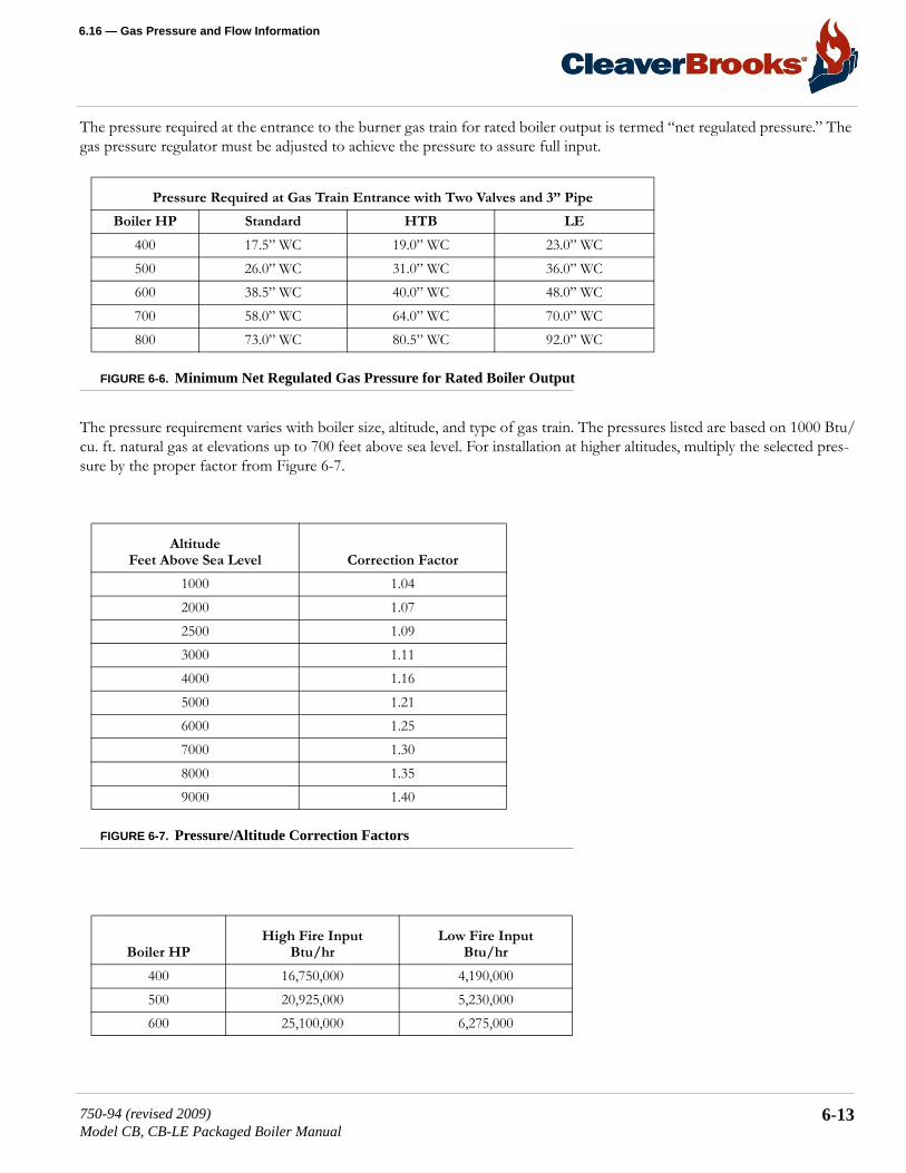
6.16 — Gas Pressure and Flow Information
The pressure required at the entrance to the burner gas train for rated boiler output is termed “net regulated pressure.” The gas pressure regulator must be adjusted to achieve the pressure to assure full input.
FIGURE 6-6. Minimum Net Regulated Gas Pressure for Rated Boiler Output
The pressure requirement varies with boiler size, altitude, and type of gas train. The pressures listed are based on 1000 Btu/cu. ft. natural gas at elevations up to 700 feet above sea level. For installation at higher altitudes, multiply the selected pres-sure by the proper factor from Figure 6-7.
FIGURE 6-7. Pressure/Altitude Correction Factors
Pressure Required at Gas Train Entrance with Two Valves and 3” Pipe
Boiler HP Standard HTB LE
400 17.5” WC 19.0” WC 23.0” WC500 26.0” WC 31.0” WC 36.0” WC600 38.5” WC 40.0” WC 48.0” WC700 58.0” WC 64.0” WC 70.0” WC800 73.0” WC 80.5” WC 92.0” WC
AltitudeFeet Above Sea Level Correction Factor
1000 1.042000 1.072500 1.093000 1.114000 1.165000 1.216000 1.257000 1.308000 1.359000 1.40
Boiler HPHigh Fire Input
Btu/hrLow Fire Input
Btu/hr
400 16,750,000 4,190,000500 20,925,000 5,230,000600 25,100,000 6,275,000
750-94 (revised 2009)Model CB, CB-LE Packaged Boiler Manual
6-13

Adjustment Procedures
FIGURE 6-8. Standard Burner Required Input
FIGURE 6-9. High Turndown Burner Required Input
FIGURE 6-10. Pressure Correction Factors
700 29,300,000 7,325,000800 33,500,000 8,375,000
Boiler HPHigh Fire Input
Btu/hrLow Fire Input
Btu/hr
400 16,750,000 1,675,000500 20,925,000 2,092,500600 25,100,000 2,510,000700 29,300,000 2,930,000800 33,500,000 3,350,000
Regulator Inlet Pressure (psig) Pressure Factor
1 1.052 1.113 1.184 1.255 1.326 1.397 1.458 1.539 1.5910 1.6611 1.7212 1.8113 1.8614 1.9315 2.00
Boiler HPHigh Fire Input
Btu/hrLow Fire Input
Btu/hr
6-14 750-94 (revised 2009)Model CB, CB-LE Packaged Boiler Manual

6.16 — Gas Pressure and Flow Information
6.16.2 — Gas Flow
The volume of gas flow is measured in terms of cubic feet and is determined by a meter reading. The gas flow rate required for maximum boiler output depends on the heating value (Btu/cu. ft.) of the gas supplied and boiler efficiency. The supply-ing utility can provide the information.
INPUT = OUTPUT x 100% EFFICIENCY
GAS FLOW = INPUT
GAS Btus/Ft3
= OUTPUT x 100
EFFICIENCY x GAS BTUs/Ft3
6.16.3 — Pressure Correction
The flow rate outlined in Section 6.16 is based on a “base” pressure, which is usually atmospheric or 14.7 psia.
Meters generally measure gas in cubic feet at “line” or supply pressure. The pressure at which each cubic foot is measured and the correction factor for the pressure must be known in order to convert the quantity indicated by the meter into the quantity which would be measured at “base” pressure.
To express the volume obtained from an actual meter reading into cubic feet at base pressure, it is necessary to multiply the meter index reading by the proper pressure factor obtained from Figure 6-10.
Conversely, to determine what the meter index reading should be in order to provide the volume of gas required for input, divide the desired flow rate by the proper pressure correction factor. This answer indicates the number of cubic feet at line pressure which must pass through the meter to deliver the equivalent number of cubic feet at base pressure.
For example, assume that a 600 horsepower boiler is installed at 2,000 feet above sea level, is equipped with a standard gas train and a high turndown burner, and that 1,000 Btu natural gas is available with in incoming gas pressure of 3 psig. The pressure and flow requirements can be determined as follows:
PRESSURE
Correction for the 2,000 feet altitude must be made since altitude has a bearing on the net regulated gas pressure. The stan-dard gas train requires 37.5” WC gas pressure at sea level. Figure 6-7 indicates a correction factor of 1.07 for 2,000 feet. Multiplying results in a calculated net regulated gas requirement of approximately 40.1” WC. This is the initial pressure to which the regulator should e adjusted. Slight additional adjustment can be made later, if necessary, to obtain the gas input needed for burner rating.
FLOW
Since the gas flow rate is based on standard conditions of flow, correction must be made for the supply pressure through the meter of 3 psig. Determine the flow rate by dividing the Btu content of the gas into the burner input (Figure 6-8) and “correct” this answer by applying the correction factor for 3 psig (Figure 6-9).
750-94 (revised 2009)Model CB, CB-LE Packaged Boiler Manual
6-15
Adjustment Procedures
Btu/hr input = CFH (Cubic feet/hour)Btu/cu. ft.
OR
25,100,000 = 25,100 CFH (at 14.7 lb atmospheric base pressure)1,000
THEN
25.100 = 21,271 CFH1.18
This is the CFH (at line pressure) that must pass through the meter so that the equivalent full input requirement of 25,100 CFH (at base pressure) will be delivered.
6.16.4 — Checking Gas Flow
Your gas supplier can generally furnish a gas meter flow chart from which gas flow can be determined. After a short obser-vation period, the information aids in adjusting the regulator to increase or decrease flow as required to obtain the rating.
Final adjustment of the gas fuel is carried out be means of the adjusting screws in the gas modulating cam, while perform-ing a combustion efficiency analysis. See Section 6.17 for details.
6.17 — Gas Fuel Combustion AdjustmentAfter operating for a sufficient period of time to assure a warm boiler, adjustments should be made to obtain efficient com-bustion.
Burner efficiency is measured by the amount or percentage of O2 present in the flue gas. O2 readings determine the total amount or excess air in the combustion process, above the point of stoichiometric combustion or perfect combustion. Stoi-chiometric combustion is a term used to describe a condition when there is the exact amount, molecule for molecule, of air for the fuel burned. This can be accomplished under laboratory conditions, however, it’s not practical to attempt to meet this condition in a boiler. Stoichiometric combustion, however, is the reference point used when setting air/fuel ratios in a boiler.
There must always be excess air in the combustion process to account for changes in boiler room temperature and atmo-spheric conditions, and to ensure the combustion is on the proper side of the combustion curve (see Figure 6-11).
Proper setting of the air/fuel ratios at all rates of firing must be established by the use of a combustion or flue gas analyzer.
NOTE: The information given in this section is for all practical purposes sufficient to set and adjust controls for gas input. Your gas supplier can, if necessary, furnish exact correction factors that take into consideration Btu content, exact base pressure, specific gravity, temperature, etc. of the gas used.
6-16 750-94 (revised 2009)Model CB, CB-LE Packaged Boiler Manual

6.17 — Gas Fuel Combustion Adjustment
The appearance or color of the gas flame is not an indication of its efficiency, because an efficient gas flame will vary from transparent blue to translucent yellow.
FIGURE 6-11. Flue Gas Analysis for Natural Gas
Most flue gas analyzers in use today measure the content, by percentage of oxygen (O2) and carbon monoxide (CO) either by percent or parts per million (ppm). Carbon dioxide (CO2) is not normally measured with today’s flue gas analyzers, but may be displayed via a calculation.
The O2 levels through the entire firing range of the burner, low-fire to high-fire should be tested. The burner manufacturer’s recommendations on turndown should also be followed and the turndown range of the burner should not be exceeded.
It is important to understand what the readings shown on an instrument refer to when setting combustion in a boiler. To assist with this understanding Figure 6-11 shows the relationship between O2 levels (excess air) and the products of com-bustion for a typical flue gas analysis (natural gas).
One of the products of combustion is CO2 (carbon dioxide). This is shown in percentage.
Another product of combustion is CO (carbon monoxide) and is shown in both percentage and parts per million (ppm). The maximum CO level standardly allowed is less than 400 ppm. However, this may change subject to local regulations.
The percent O2 recorded on an instrument equates to percent excess air, i.e., 3% O2 is approximately 15% excess air and 4% O2 is approximately 20% excess air. The exact percentage of excess air is a mathematical calculation based on an ultimate fuel analysis of the fuel being fired.
It is generally recommended that O2 readings of between 3% and 4% be attained with less than 400 ppm CO, at high-fire.
Using information from section 6.16, determine the standard conditions of gas pressure and flow for the boiler size and attached gas train. Calculate the actual pressure and flow through the use of correction factors that compensate for incom-ing gas pressure and altitude.
750-94 (revised 2009)Model CB, CB-LE Packaged Boiler Manual
6-17

Adjustment Procedures
Basically, gas adjustments are made with a gas pressure regulator, which controls the pressure and with the butterfly gas valve which directly controls the rate of flow.
FIGURE 6-12. Butterfly Gas Valve
In initially setting the linkage:
1. Back off the low fire stop screw on the butterfly valve so that the valve is closed. 2. Then run the screw out to touch the arm, and give it two complete turns. 3. Adjust the connecting rod so that the override tension is released and so that the arm is now just touching the stop
screw. 4. Tighten the locknuts on all ball joints.
The low fire setting should be regarded as tentative until the proper gas pressure for high-fire operation is established. To reach high-fire rate:
1. Turn the manual flame control switch toward “OPEN” in minor increments while monitoring combustion for overly rich or lean conditions.
2. At high-fire the gas butterfly valve should be open as wide as indicated by the slot on the end of the shaft. Set and lock the high-fire stop screw so that it is just touching the valve arm.
3. Determine the actual gas flow from a meter reading.4. With the butterfly valve open and with regulated gas pressure set at the calculated pressure, the actual flow rate should
be close to the required input. If corrections are necessary, increase or decrease the gas pressure by adjusting the gas pressure regulator, following the manufacturer’s directions for regulator adjustment.
When proper gas flow is obtained, take a flue gas reading. The O2 should be between 3% and 4% at high-fire.
If the fuel input is correct, but the O2 values do not fall within this range, the air damper travel may need to be adjusted. Adjustment of the air damper linkage is described in Section 6.2.
With the high-fire air/fuel ratio established, the gas pressure regulator needs no further adjusting.
6-18 750-94 (revised 2009)Model CB, CB-LE Packaged Boiler Manual
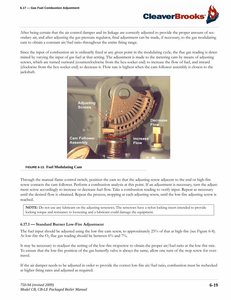
6.17 — Gas Fuel Combustion Adjustment
After being certain that the air control damper and its linkage are correctly adjusted to provide the proper amount of sec-ondary air, and after adjusting the gas pressure regulator, final adjustment can be made, if necessary, to the gas modulating cam to obtain a constant air/fuel ratio throughout the entire firing range.
Since the input of combustion air is ordinarily fixed at any given point in the modulating cycle, the flue gas reading is deter-mined by varying the input of gas fuel at that setting. The adjustment is made to the metering cam by means of adjusting screws, which are turned outward (counterclockwise from the hex-socket end) to increase the flow of fuel, and inward (clockwise from the hex-socket end) to decrease it. Flow rate is highest when the cam follower assembly is closest to the jackshaft.
FIGURE 6-13. Fuel Modulating Cam
Through the manual flame control switch, position the cam so that the adjusting screw adjacent to the end or high-fire screw contacts the cam follower. Perform a combustion analysis at this point. If an adjustment is necessary, turn the adjust-ment screw accordingly to increase or decrease fuel flow. Take a combustion reading to verify input. Repeat as necessary until the desired flow is obtained. Repeat the process, stopping at each adjusting screw, until the low-fire adjusting screw is reached.
6.17.1 — Standard Burner Low-Fire Adjustment
The fuel input should be adjusted using the low-fire cam screw, to approximately 25% of that at high-fire (see Figure 6-8). At low-fire the O2 flue gas reading should be between 6% and 7%.
It may be necessary to readjust the setting of the low-fire stopscrew to obtain the proper air/fuel ratio at the low-fire rate. To ensure that the low-fire position of the gas butterfly valve is always the same, allow one turn of the stop screw for over-travel.
If the air damper needs to be adjusted in order to provide the correct low-fire air/fuel ratio, combustion must be rechecked at higher firing rates and adjusted as required.
NOTE: Do not use any lubricant on the adjusting setscrews. The setscrews have a nylon locking insert intended to provide locking torque and resistance to loosening and a lubricant could damage the equipment.
750-94 (revised 2009)Model CB, CB-LE Packaged Boiler Manual
6-19

Adjustment Procedures
If all cam screws are properly adjusted, none will deviate from the general overall contour of the cam face.
6.17.2 — High Turndown Burner Low-Fire Adjustment
The fuel input should be adjusted using the low-fire cam screw, to approximately 10% of that at high-fire (see Figure 6-9). At low-fire the O2 flue gas reading should be between 9.5% and 11%.
It may be necessary to readjust the setting of the low-fire stopscrew in order to obtain the proper air/fuel ratio at low-fire. To ensure that the low-fire position of the gas butterfly valve is always the same, allow a half turn of the stop screw for overtravel.
If the air damper must be reset to meet the low-fire air/fuel requirements, combustion at higher firing rates must be rechecked.
The second cam adjusting screw may need to be adjusted in order to maintain a smooth cam profile. If all screws are prop-erly adjusted, none will deviate from the general overall contour of the cam face.
6.18 — Low-Gas Pressure SwitchAdjust the scale setting to slightly below the normal burning pressure. The control circuit will be broken when pressure falls below this point. Since gas line distribution pressure may decrease under some conditions, shutdowns may result if the set-ting is too close to normal. However, regulations require that the setting may not be less than 50% of the rated pressure downstream of the regulator.
Manual resetting is necessary after a pressure drop. Press the reset lever after pressure is restored. Be sure that the mercury switch equipped control is level.
6.19 — High-Gas Pressure SwitchAdjust the scale setting to slightly above the normal burning pressure. The control circuit will be broken when pressure exceeds the normal operating pressure. Unnecessary shutdowns may result if the setting is too close to normal, however, regulations require that the setting may not be greater than 150% of rated pressure.
6-20 750-94 (revised 2009)Model CB, CB-LE Packaged Boiler Manual

6.20 — Fuel Oil Pressure and Temperature: General
Manual resetting is necessary after a pressure rise. Press the reset lever after pressure falls. Be sure that the mercury switch equipped control is level.
FIGURE 6-14. Gas Train Pressure Switches
6.20 — Fuel Oil Pressure and Temperature: GeneralVariations in burning characteristics of the fuel oil may occasionally require adjustments to assure highest combustion effi-ciency. The handling and burning characteristics may vary from one delivery of oil to another. Therefore, it is recommended that the oil system be inspected from time to time to verify that pressures and viscosity are at the proper operating levels.
Because of variation in oils, including chemical content, source, blends, and viscosity characteristics, the temperatures and pressures listed in Chapter 5, and mentioned in the adjusting of the controls in the following paragraphs, will vary and thus may be regarded as tentative and to be changed to provide best firing conditions. Figure 6-15 is an oil viscosity-temperature chart. It may be used as a guide, although your oil supplier will be able to give you more exact information based on an anal-ysis of the oil.
750-94 (revised 2009)Model CB, CB-LE Packaged Boiler Manual
6-21

Adjustment Procedures
FIGURE 6-15. Oil Viscosity Chart
Review of the applicable maintenance instructions given in Chapter 8 will aid in maintaining an efficient fuel system.
When the boiler is shut down, or switched over to gas firing, the pump must operate for a sufficient period of time to cool the oil heater. Similarly, if an electric, steam, or hot water oil heater is removed for servicing, the temperature of the heater should be reduced by circulating oil until it has cooled.
6.21 — Fuel Oil Combustion AdjustmentAfter operating for a sufficient period of time to assure a warm boiler, adjustments should be made to obtain efficient com-bustion.
Burner efficiency is measured by the amount or percentage of O2 present in the flue gas. O2 readings determine the total amount or excess air in the combustion process, above the point of stoichiometric combustion or perfect combustion. Stoi-chiometric combustion, however, is the reference point used when setting air/fuel ratios in a boiler.
There must always be excess air in the combustion process to account for changes in boiler room conditions and to ensure the combustion is on the proper side of the combustion curve.
Proper setting of the air/fuel ratios at all rates of firing must be established by the use of a combustion gas analyzer. Effi-cient combustion cannot be solely judged by flame condition or color, although they may be used in making approximate settings. Combustion settings should be done so that there is a bright sharp flame with no visible haze.
NOTE: To prevent oil heater coking, the fuel oil pump must be in operation during all times that an oil heater is in service. During any time that the oil pump is not operating, the oil heating system must be electrically shut down by manually turn-ing the oil heater switch to the “off ” position.
6-22 750-94 (revised 2009)Model CB, CB-LE Packaged Boiler Manual

6.21 — Fuel Oil Combustion Adjustment
Most flue gas analyzers in use today measure the content, by percentage, of oxygen (O2) and in some cases, smoke. Carbon dioxide (CO2) is not normally measured with modern gas analyzers, but may be displayed as a calculation.
The O2 levels through the entire firing range of the burner, low-fire to high-fire should be tested. The burner manufacturer’s recommendations on turndown should also be followed and the turndown range of the burner should not be exceeded.
It is required to set the burner to operate with a reasonable amount of excess air to compensate for minor variations in the pressure, temperature, or burning properties of oil. 15% to 20% excess air is considered reasonable. This would result in an O2 reading of 3% to 4% at high-fire.
Final adjustment to fuel input must be made to produce a minimum of smoke. A maximum smoke spot density of a No. 2 for light oil, or a No. 4 for heavy oil is acceptable, as measured in conformance to ASTMD 2156-63T.
Through the use of the manual flame control, slowly bring the unit to high-fire by stages while monitoring combustion for overly rich or lean conditions. At the high-fire position, the air damper should be fully opened and the air and oil pressure readings should be on the order of the readings given in Chapter 5.
Take a flue gas analysis reading. If necessary, adjust the fuel oil controller to increase or decrease oil pressure. Adjustments to the pressure should be done before attempting to adjust the screws in the metering cam. Ideally, the cam profile spring should be as close to the cam casting as practical. It is more desirable to lower the oil pressure to reduce flow, if necessary, than to extend the adjusting screws to an extreme position in an effort to cut back flow.
After being certain that the air control damper and its linkage are operating properly, final adjustment can be made, if neces-sary, to the oil modulating cam to obtain a constant air/fuel ratio through the entire firing range.
Since the input of combustion air is ordinarily fixed at any given point in the modulating cycle, the flue gas reading is deter-mined by varying the input of fuel at that setting. The adjustment is made to the metering cam by means of adjusting screws, which are turned out (counterclockwise from the hex-socket end) to increase the flow of fuel and in (clockwise from the hex-socket end) to decrease it. Flow rate is highest when the cam follower assembly is closest to the jackshaft.
If oil pressure, primary air pressure, and linkages are properly adjusted, the metering cam should require minimal adjust-ment.
Using the flame control switch, position the cam so that the adjusting screw adjacent to the end, high-fire screw, contacts the cam follower. Make a combustion analysis at this point.
If an adjustment is necessary, turn the adjustment screw accordingly to increase or decrease fuel flow. Take a combustion reading to verify input. Repeat as necessary until the desired flow is obtained. Continue this pressure, stopping at each adjusting screw, until the low-fire position is reached.
6.21.1 — Standard Burner Low-Fire Adjustment: Heavy Oil
The fuel input should be adjusted with the low-fire cam screw, to approximately 25% of that at high-fire. At low fire the O2 flue gas reading should be between 7% and 8%.
NOTE: Do not use any lubricant on the adjusting setscrews. These have a nylon locking insert intended to provide locking torque and resistance to loosening and a lubricant could damage the equipment.
750-94 (revised 2009)Model CB, CB-LE Packaged Boiler Manual
6-23
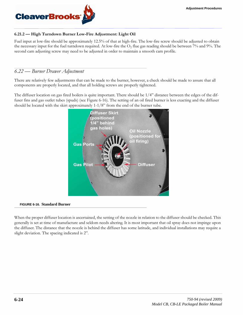
Adjustment Procedures
6.21.2 — High Turndown Burner Low-Fire Adjustment: Light Oil
Fuel input at low-fire should be approximately 12.5% of that at high-fire. The low-fire screw should be adjusted to obtain the necessary input for the fuel turndown required. At low-fire the O2 flue gas reading should be between 7% and 9%. The second cam adjusting screw may need to be adjusted in order to maintain a smooth cam profile.
6.22 — Burner Drawer AdjustmentThere are relatively few adjustments that can be made to the burner, however, a check should be made to assure that all components are properly located, and that all holding screws are properly tightened.
The diffuser location on gas fired boilers is quite important. There should be 1/4” distance between the edges of the dif-fuser fins and gas outlet tubes (spuds) (see Figure 6-16). The setting of an oil fired burner is less exacting and the diffuser should be located with the skirt approximately 1-1/8” from the end of the burner tube.
FIGURE 6-16. Standard Burner
When the proper diffuser location is ascertained, the setting of the nozzle in relation to the diffuser should be checked. This generally is set at time of manufacture and seldom needs altering. It is most important that oil spray does not impinge upon the diffuser. The distance that the nozzle is behind the diffuser has some latitude, and individual installations may require a slight deviation. The spacing indicated is 2”.
6-24 750-94 (revised 2009)Model CB, CB-LE Packaged Boiler Manual

6.22 — Burner Drawer Adjustment
Check the setting of the ignition electrode(s) for proper gap and position. Be sure that the porcelain insulator is not cracked and that ignition cable connections are tight.
FIGURE 6-17. Burner Drawer With Gas Pilot
The oil nozzle tip should be seated tightly in the body with the swirler and the seating spring in place. See Section 8.7 for additional nozzle tip information.
FIGURE 6-18. Electrode Setting: Oil Pilot
Check to see that the flame detector sight tube and the gas pilot tube extend through their respective openings in the dif-fuser face.
750-94 (revised 2009)Model CB, CB-LE Packaged Boiler Manual
6-25

Adjustment Procedures
6.23 — Oil Drawer SwitchThe integral contacts of the control are closed by proper positioning and latching of the oil drawer in its forward position. Adjustment of the switch must be such that its contacts open if the oil drawer is not properly positioned for oil firing. The switch is electrically removed from the circuit when a combination fuel burner is fired on gas.
6.24 — Low Oil Temperature SwitchThe LOTS prevents the burner from starting, or stops its operation, if the temperature of the oil is below normal operating temperature.
To adjust the control:
1. Insert a screwdriver into the center slot in the control cover and turn the dial until the fixed (center) pointer is approxi-mately 30º F lower than the oil heater thermostat setting.
2. Turn the differential adjusting screw (located above dial) until the movable indicator is approximately 5º F above the set-ting on the main scale.
On a hot water boiler, the low oil temperature switch is an integral part of the electric oil heater. The switch is non-adjust-able and is factory set at approximately 40º F below the maximum operating temperature of the heater.
6.25 — High Oil Temperature Switch (Optional)The HOTS prevents the burner from starting, or stops its operation, if the temperature of the oil exceeds the normal oper-ating temperature.
To adjust, turn the dial until the pointer is approximately 25º F above the normal operating temperature. The controls gen-erally have a set differential and will close 5º F below the setpoint.
6.26 — Low Oil Pressure Switch (Optional)The LOPS prevents burner ignition, or stops its operation, when the oil pressure is below the setpoint. Adjust the control by turning the screw on top of the control case to an indicated pressure 10 psi below the established primary oil pressure setting indicated on the oil supply pressure gauge. The switch will remain in a closed position as long as the oil pressure exceeds this setting. The control normally used automatically resets when pressure is restored after a drop.
6.27 — Electric Oil Heater Thermostat (400 and 600 Series: Steam)The maximum temperature setting of the control is stamped on the dial. The maximum temperature setting is attained with the adjusting knob turned to the “high” end of the scale. Lower settings are obtained by turning the adjusting knob clock-wise using the thermometer in the fuel oil controller as a guide.
6-26 750-94 (revised 2009)Model CB, CB-LE Packaged Boiler Manual

6.28 — Steam Oil Heater Thermostat: No. 6 Oil
The final setting of this thermostat should be at a temperature approximately 15º F lower than the steam heater thermostat. This eliminates the electric heater operation when the steam heater is functioning. The electric heater is sized to provide suf-ficient heated oil for low-fire operation on cold starts before steam is available.
6.28 — Steam Oil Heater Thermostat: No. 6 Oil
(400 and 600 Series: Steam)The maximum temperature setting of the control is stamped on the dial. The maximum temperature setting is attained with the adjusting knob turned to the “high” end of the scale. Lower settings are obtained by turning the adjusting knob clock-wise using the thermometer in the fuel oil controller as a guide.
The final setting of the thermostat should provide oil at a sufficient temperature for efficient combustion based on flue gas analysis. There is no need to heat the oil in excess of the temperature.
6.29 — Hot Water Oil Heater Thermostat (400 and 600 Series)To adjust the thermostat, insert a screwdriver into the center slot in the control cover and turn the dial until the pointer is at the desired temperature level. The control generally has a set differential, and will close 5º F below the setpoint.
The thermostat contacts close to energize the booster water pump, which pumps water from the boiler through the heater. On cold starts, it is normal practice to manually close the valve in the pump discharge line until the boiler water temperature exceeds the temperature of fuel oil entering the heater.
The electric oil heater on a hot water boiler burning No. 6 oil and equipped with a hot water oil heater has a built-in adjust-able thermostat. The maximum temperature setting is stamped on its dial. The desired temperature can be obtained by turn-ing the adjusting screw. The thermostat should be set at a temperature approximately 15 degrees lower than the hot water heater thermostat. Such a temperature prevents the electric heater from operation when the water heater is functioning. The electric heater is sized to provide sufficient heated oil for low-fire operation on cold starts before hot water is available.
6.30 — Steam Heater Pressure Regulator (400 and 600 Series: Steam)The regulator is provided on a boiler designed to operate at pressures above 15 psi and reduces boiler steam pressure to the level necessary for proper operation of the steam oil heater. The pressure should be reduced to a point that permits suffi-cient temperature to heat the oil, while allowing as continuous a steam flow as possible. Pressure that is too high will result in frequent cycling of the steam solenoid valve.
It is best to adjust the regulator under typical flow conditions. To do so, it is suggested that the globe valve in the steam sup-ply line be closed so that there is no pressure on the regulator. Turn out the adjusting screw fully to relieve compression on the regulator spring, thus closing the regulator. With steam at normal pressure, open the globe valve and then set the sec-ondary pressure by turning the adjusting screw or handle until the downstream gauge shows the desired pressure.
750-94 (revised 2009)Model CB, CB-LE Packaged Boiler Manual
6-27

Adjustment Procedures
6-28 750-94 (revised 2009)Model CB, CB-LE Packaged Boiler Manual

CHAPTER 7 Troubleshooting
7.1 — Overview
Chapter 7 assumes that the unit has been properly installed and adjusted, and that it has been running for some time. It is further assumed that the operator has become thoroughly familiar with both burner and manual by this time. The points under each heading are set down briefly as possible causes, and suggestions or clues to simplify locating the source of trou-ble. Methods of correcting the trouble, once it has been identified, may be found elsewhere in this manual.
If the burner will not start or operate properly, the troubleshooting chapter should be referred to for assistance in pinpoint-ing problems that may not be readily apparent.
The program relay has the capability to self-diagnose and to display a code or message that indicates the failure condition. Refer to the control bulletin for specifics and suggested remedies.
Familiarity with the programmer and other controls in the system may be obtained by studying the contents of this manual. Knowledge of the system and its controls will make troubleshooting much easier. Costly downtime or delays can be pre-vented by systematic checks of actual operation against the normal sequence to determine the stage at which performance
Troubleshooting should be performed only by personnel who are familiar with the equipment and who have read and under-stand the contents of this manual. Failure to follow these instructions could result in serious injury or death.
Disconnect and lock out the main power supply in order to avoid the hazard of electrical shock. Failure to follow these instruc-tions could result in serious injury or death.
NOTE: The make or model of the program relay provided will vary depending upon job specifications. The following sequence applies regardless of the make or model. Please refer to the Wiring Diagram (WD) prepared by Cleaver-Brooks for your specific installation.
! Warning
! Warning
750-94 (revised 2009)Model CB, CB-LE Packaged Boiler Manual
7-1

Troubleshooting
deviates from normal. Following a routine may possibly eliminate overlooking an obvious condition, often one that is rela-tively simple to correct.
If an obvious condition is not apparent, check the continuity of the circuits with a voltmeter or test lamp. Each circuit can be checked and the fault isolated and corrected. Most circuitry checking can be done between appropriate terminal on the terminal boards in the control cabinet or the entrance box. Refer to the schematic wiring diagram for terminal identifica-tion.
Problem Possible Cause(s)
BURNER DOES NOT START
1. No voltage at program relay power input terminals.A. Main disconnect switch open.B. Blown control circuit fuse.C. Loose or broken electrical connection.
2. Program relay safety switch requires resetting.3. Limit circuit not completed - no voltage at end of limit circuit program
relay terminal.A. Pressure or temperature is above setting of operation control. (Load
demand light will not glow.)B. Water below required level.
1) Low-water light (and alarm horn) should indicate this condition.2) Check manual reset button (if provided) on low-water control.
C. Fuel pressure must be within settings of low pressure and high pres-sure switches.
D. Oil fired unit - burner gun must be in full forward position to close oil drawer switch.
E. Heavy oil fired unit - oil temperature below minimum settings.4. Fuel valve interlock circuit not completed.
A. Fuel valve auxiliary switch not enclosed.
7-2 750-94 (revised 2009)Model CB, CB-LE Packaged Boiler Manual

7.1 — Overview
NO IGNITION 1. Lack of spark.A. Electrode grounded or porcelain cracked.B. Improper electrode setting.C. Loose terminal on ignition cable - or cable shorted.D. Inoperative ignition transformer.E. Insufficient or no voltage at pilot ignition circuit terminal.
2. Spark but no flame.A. lack of fuel - no gas pressure, closed valve, empty tank, broken line,
etc.B. Inoperative pilot solenoid.C. Insufficient or no voltage at pilot ignition circuit terminal.D. Too much air.
3. Low-fire switch open in low-fire proving circuit.A. Damper motor not closed, slipped cam, defective switch.B. Damper jammed or linkage binding.
4. Running interlock circuit not completed.A. Combustion or atomizing air proving switches defective or not
properly set.B. Motor starter interlock contact not closed.
5. Flame detector defective, sight tube obstructed, or lens dirty.
PILOT FLAME, BUT NO MAIN FLAMW
1. Insufficient pilot flame.2. Gas fired unit:
A. Manual gas cock closed.B. Main gas valve inoperative.C. Gas pressure regulator inoperative.
3. Oil fired unit:A. Oil supply cut off by obstruction, closed valve, or loss of suction.B. Supply pump inoperative.C. No fuel.D. Main oil valve inoperative.E. Check oil nozzle, gun, and lines.
4. Flame detector defective, sight tube obstructed or lens dirty.5. Insufficient or no voltage at main fuel valve circuit terminal.
BURNER STAYS IN LOW-FIRE
1. Pressure or temperature above modulating control setting.2. Manual-automatic switch in wrong position.3. Inoperative modulating motor.4. Defective modulating control.5. Binding or loose linkage, cams, setscrews, etc.
Problem Possible Cause(s)
750-94 (revised 2009)Model CB, CB-LE Packaged Boiler Manual
7-3

Troubleshooting
SHUTDOWN OCCURS DURING FIRING
1. Loss or stoppage of fuel supply.2. Defective fuel valve, loose electrical connection.3. Flame detector weak or defective.4. Lens dirty or sight tube obstructed.5. If the programmer lockout switch has not tripped, check the limit cir-
cuit for an opened safety control.6. If the programmer lockout switch has tripped:
A. Check fuel lines and valves.B. Check flame detector.C. Check for open circuit in running interlock circuit.D. The flame failure light is energized by ignition failure, main flame
failure, inadequate flame signal, or open control in the running interlock circuit.
7. Improper air/fuel ratio (lean fire):A. Slipping linkage.B. Damper stuck open.C. Fluctuating fuel supply:
1) Temporary obstruction in fuel line.2) Temporary drop in gas pressure.3) Orifice gate valve open.
8. Interlock device inoperative or defective.
MODULATING MOTOR DOES NOT OPERATE
1. Manual-automatic switch in wrong position.2. Linkage loose or jammed.3. Motor does not drive to open or close during pre-purge or close on
burner shutdown:A. Motor defective.B. Loose electrical connection.C. Damper motor transformer defective.
4. Motor does not operate on demand:A. Manual-automatic switch in wrong position.B. Modulating control improperly set or inoperative.C. Motor defective.D. Loose electrical connection.E.Damper motor transformer defective.
Problem Possible Cause(s)
7-4 750-94 (revised 2009)Model CB, CB-LE Packaged Boiler Manual
CHAPTER 8 Inspection and Maintenance
8.1 — Overview
A well planned maintenance program will help avoid unnecessary downtime or costly repairs, promote safety, and aid boiler inspectors. An inspection schedule with a listing of procedures should be established. It is recommended that a boiler room log or record be maintained. Recording of daily, weekly, monthly, and yearly maintenance activities provides a valuable guide and aids in obtaining economical and lengthy service from Cleaver-Brooks equipment. A sample boiler inspection schedule is provided at the end of this chapter. It is important to realize that the frequency of inspection will depend on variable con-ditions such as load, fuel, system requirements, boiler environment (indoor/outdoor), etc.
Good housekeeping helps maintain a professional appearing boiler room. Only trained and authorized personnel should be permitted to operate, adjust, or repair the boiler and its related equipment. The boiler room should be kept free of all mate-rial and equipment not necessary to the operation of the boiler or heating system.
Even though the boiler has electrical and mechanical devices that make it automatic or semi-automatic in operation, the devices require systematic and periodic maintenance. Any automatic feature does not relieve the operator from responsibil-ity, but rather frees the operator from certain repetitive chores providing time to devote to upkeep and maintenance.
Alertness in recognizing an unusual noise, improper gauge reading, leaks, etc., can make the operator aware of a developing malfunction and permit prompt corrective action that may prevent extensive repairs or unexpected downtime. Any leaks — fuel, water, steam, exhaust gas — should be repaired promptly and under conditions that observe necessary safety precau-tions. Preventive maintenance measures, such as regularly checking the tightness of connections, locknuts, setscrews, pack-ing glands, etc., should be included in regular maintenance activities.
NOTE: For more information on your flame safeguard system, refer to the appropriate manual that was provided with your boiler.
Inspection and maintenance should be performed only by trained personnel who are familiar with this equipment. Failure to follow these instructions could result in equipment damage.
! Caution
750-94 (revised 2009)Model CB, CB-LE Packaged Boiler Manual
8-1

Inspection and Maintenance
8.1.1 — Periodic Inspection
Insurance regulations and local laws require periodic inspection of the pressure vessel by an authorized inspector. Section 3.8 in Chapter 3 contains information relative to the inspection.
Inspections are usually, though not necessarily, scheduled for periods of normal boiler downtime, such as an off season. This major inspection can often be used to accomplish maintenance, replacement or repairs that cannot easily be done at other times. Inspection also serves as a good basis for establishing a schedule for annual, monthly, or other periodic mainte-nance programs.
While the inspection pertains primarily to the waterside and fireside surfaces of the pressure vessel it provides the operator an excellent opportunity for detailed inspection and check of all components of the boiler, including piping, valves, pumps, gaskets, refractory, etc. Comprehensive cleaning, spot painting or repainting, and the replacement of expendable items should be planned for and taken care of during this time. Any major repairs or replacements that may be required should also, if possible, be coordinated with the period of boiler shutdown.
Replacement spare parts, if not on hand, should be ordered sufficiently prior to shutdown.
Cleaver-Brooks boilers are designed, engineered, and built to provide long life and excellent service. Good operating prac-tices and conscientious maintenance and care will assure efficiency and economy from their operation, and will contribute to many years of performance.
A total protection plan includes a Planned Maintenance Program that covers many of the items included in this chapter.
For information regarding a total protection plan, contact your local Cleaver-Brooks authorized representative.
8.2 — Fireside CleaningSoot and non-combustibles are effective insulators, and, if allowed to accumulate, will reduce heat transfer to the water and increase fuel consumption. Soot and other deposits can be very moisture-absorbent, and may attract moisture to form cor-rosive acids that will deteriorate fireside metal.
Cleanout should be performed at regular and frequent intervals, depending upon load, type, and quality of fuel. internal boiler temperature, and combustion efficiency. A stack temperature thermometer can be used as a guide to cleanout inter-vals since an accumulation of soot deposits will raise the flue gas temperature.
Tube cleaning is accomplished by opening the front and rear doors. Tubes may be brushed from either end. All loose soot and accumulations should be removed. Any soot, or other deposits, should be removed from the furnace and tube sheets.
Refer to Section 8.17 for instructions on properly closing rear heads.
The flue gas outlet and stack should be inspected annually and cleaned as necessary. Commercial firms are available to per-form the work. The stack should be inspected for damage and repaired as required.
The fireside should be thoroughly cleaned prior to any extended lay-up of the boiler. Depending upon circumstances, a pro-tective coating may be required. See Section 3.9 in Chapter 3.
NOTE: Cleaver-Brooks genuine parts should be used to ensure proper operation. Contact your local Cleaver-Brooks rep-resentative for parts information and ordering.
8-2 750-94 (revised 2009)Model CB, CB-LE Packaged Boiler Manual

8.3 — Water Level Controls
8.3 — Water Level ControlsThe need to periodically check water level controls and the waterside of the pressure vessel cannot be overemphasized. Most instances of major boiler damage are the result of operating with low water, or the use of untreated (or incorrectly treated) water.
Always be sure of the boiler water level. On steam boilers, the water column should be blown down daily. Check samples of boiler water and condensate in accordance with procedures recommended by your local Cleaver-Brooks authorized repre-sentative. Refer to Sections 3.7 and 3.8 in Chapter 3 for blowdown instructions and internal inspection procedures.
Since low-water cutoff devices are generally set by the original manufacturer, no attempt should be made to adjust these controls to alter the point of low-water cutoff or point of pump cut-in or cut-out. If a low-water device should become erratic in operation, of if its setting changes from previously established levels, contact your local Cleaver-Brooks authorized representative.
8.3.1 — Steam Boiler
FIGURE 8-1. Low Water Cutoff
The low water cutoff controls normally function for long periods of time, which may lead to laxity in testing on the assump-tion that normal operation will continue indefinitely.
On a steam boiler, the head mechanism of the low water cutoff device(s) should be removed from the bowl at least semi-annually to check and clean the float ball, the internal moving parts, and the bowl or water column.
Safe operation of your generator demands periodic inspection and maintenance of all low water cutoff devices. Open and inspect them at least once a month. Under constant attendance and with the burner in lo-fire position, check operation fre-quently by stopping water flow to the generator and allowing the water level to lower. If controls do not cut off the burner at the proper safe water level, or appear to be in poor physical condition, repair or replace at once.
! Warning
750-94 (revised 2009)Model CB, CB-LE Packaged Boiler Manual
8-3
Inspection and Maintenance
Remove the pipe plugs from the tees or crosses and make certain the cross-connecting piping is clean and free of obstruc-tions. Controls must be mounted in a plumb position for proper performance. Determine that piping is vertically aligned after shipment and installation and throughout life of the equipment.
A blowdown of the water controls on a steam boiler should be performed daily.
8.3.2 — Hot Water Boiler
It is impractical to blowdown the low water cutoff device(s) on a hot water boiler since the entire water content of the sys-tem would become involved. Many hot water systems are fully closed and any loss of water will require make-up and addi-tional feedwater treatment that might not otherwise be necessary. Since the boiler and system arrangement usually make it impractical to perform daily and monthly maintenance of the low water cutoff device(s), it is essential to verify proper oper-ation. Remove the operating mechanism from the bowl annually or more frequently, if possible, to check and clean the float ball, internal moving parts, and the bowl housing. Also check the cross-connecting piping to be certain that it is clean and free of obstruction.
8.4 — Water Gauge GlassA broken or discolored glass should be replaced at once. Periodic replacement should be a part of the maintenance pro-gram. Always use new gaskets when replacing a glass. Use a Proper size rubber packing. Do not use loose packing, which could be forced below the glass and possibly plug the valve opening.
1. Close the valves when replacing the glass. 2. Slip a packing nut, a packing washer, and packing ring onto each end of the glass. Insert one end of the glass into the
upper gauge valve body far enough to allow the lower end to be dropped into the lower body. 3. Slide the packing nuts onto each valve and tighten. 4. It is recommended that the boiler is off and cool when the glass is replaced. However, if the glass is replaced while the
boiler is in service, open the blowdown and slowly bring the glass to operating temperature by opening the gauge valves slightly.
5. After the glass is warmed up, close the blowdown valve and open the gauge valves completely.
6. Check try cocks and gauge cocks for freedom of operation and clean as required. It is imperative that the gauge cocks are mounted in exact alignment. If they are not, the glass will be strained and may fail prematurely.
8.5 — Electrical ControlsThe operating controls should be inspected monthly. Examine tightness of electrical connections and keep the controls clean. Remove any dust that accumulates in the interior of the control using a low pressure air. Take care not to damage the mechanism.
Examine any mercury tube switches (if older device is being used) for damage or cracks. Dark scum over the normally bright surface of the mercury may lead to erratic switching action. Be certain that controls are correctly leveled. The piping leading to the pressure control actuators should be cleaned, if necessary. Covers should be left on controls at all times.
Do not attempt to change the gauge glass while the boiler is in service. Failure to follow these instructions could result in serious injury or death.
! Warning
8-4 750-94 (revised 2009)Model CB, CB-LE Packaged Boiler Manual

8.5 — Electrical Controls
Dust and dirt can cause excessive wear and overheating of motor starter and relay contacts. Use a burnishing tool or a hard surface paper to clean and polish contacts. Starter contacts are plated with silver and are not harmed by discoloration and slight pitting. Replacement of the contacts is necessary only if the silver has worn thin.
FIGURE 8-2. Recommended Maximum “Fusetron” Fuse Sizes
Thermal relay units (overloads) are of the melting-alloy type and, when tripped, the alloy must be given time to re-solidify before relay can be reset. IF the overloads trip out repeatedly when the motor current is normal, replace them with new overloads. If the condition continues after replacement, it will be necessary to determine the cause of excessive current draw at the overloads.
Do not use files or abrasive materials such as sandpaper on the contact points. Failure to follow these instructions could result in equipment damage.
! Caution
750-94 (revised 2009)Model CB, CB-LE Packaged Boiler Manual
8-5

Inspection and Maintenance
Power supply to the boiler must be protected with dual element fuses (fusetrons) or circuit breakers. Similar fuses should be used in branch circuits. Standard one-shot fuses are not recommended. Refer to the chart in Figure 8-2 for fuse requirement guidance.
8.6 — Flame Safety ControlThe microprocessor based control requires minimal maintenance because the safety and logic timings are inaccessible. There also are not any accessible contacts. Check to see that the retaining screw is securely holding the chassis to the mounting base. Also check to see that the amplifier and the program module are tightly inserted.
The relay’s self-diagnostic ability includes advising when it or its plug-in modules are at fault and require replacement.
Your spare control should be stored in a dry atmosphere and wrapped in plastic. During an extended shutdown (e.g., sea-sonal) the active control should be removed and stored. Moisture can cause problems with control operation.
It is recommended that service be rotated between the active and a spare control to assure a working replacement is avail-able.
Be sure the connecting contacts on the control and its base are not bent out of position.
The flame detector lens should be cleaned as often as operating conditions demand. Use a soft cloth moistened with deter-gent to clean the lens.
A safety check procedure should be established to test the complete safeguard system at least once a month, or more often. Tests should verify safety shutdown and a safety lockout upon failure to ignite the pilot, upon failure to ignite the main flame, and upon loss of flame. Each of the conditions should be checked on a scheduled basis.
The following tests should be used to test the complete safeguard system. If the sequence of events is not as described, then a problem may exist. Contact your local Cleaver-Brooks authorized representative for assistance.
8.6.1 — Checking Pilot Flame Failure
1. Close the gas pilot shutoff cock and shut off the main fuel supply.2. Turn the burner switch “on.”
The pilot ignition circuit will be energized at the end of the pre-purge period. There should be an ignition spark, but no flame. Since there is no flame to be detected, the program relay will signal the condition. The ignition circuit will de-energize and the control will lock out on a safety shutdown. The flame failure light (and optional alarm) will be activated. The blower motor will run through the post-purge and stop.
3. Turn the burner switch “off.”4. Reset the safety switch.5. Re-open the gas pilot shutoff cock and re-establish main fuel supply.
When replacing a control, be sure to lock out the main power supply switch since the control is “hot” even though the burner switch is off. Failure to follow these instructions could result in serious injury or death.
! Warning
8-6 750-94 (revised 2009)Model CB, CB-LE Packaged Boiler Manual

8.7 — Oil Burner Maintenance
8.6.2 — Checking Failure to Light Main Flame
1. Leave the gas pilot shutoff cock open.2. Shut off the main burner fuel supply. 3. Turn the burner switch “on.”
The pilot will light upon completion of the pre-purge period. The main fuel valve(s) will be energized, but there should be no main flame.The fuel valve(s) de-energize within 4 seconds after the main burner ignition trial ends. The control will lock out on a safety shutdown. The flame failure light (and optional alarm) will be activated. The blower motor will run through the post-purge and stop.
4. Turn the burner switch “off.”5. Reset the safety switch.6. Re-establish main fuel supply.
8.6.3 — Checking Loss of Flame
1. With the burner in normal operation, shut off the main burner fuel supply to extinguish main flame.The fuel valve(s) will be de-energized and the relay will signal the condition within 4 seconds. The control will then lock out on a safety shutdown. The flame failure light (and optional alarm) will be activated. The blower motor will run through the post-purge and stop.
2. Turn the burner switch “off.”3. Reset the safety switch.4. Re-establish main fuel supply.5. The flame detector lens should be cleaned as often as operating conditions demand. Use a soft cloth moistened with
detergent, if necessary.
8.7 — Oil Burner MaintenanceThe burner should be inspected for evidence of damage due to improperly adjusted combustion. Any soot buildup on the diffuser or the oil nozzle should be removed. The setting of the oil nozzle in relation to the diffuser and other components is important for proper firing and should be checked.
8.7.1 — Oil Strainers
Oil strainers should be cleaned frequently to maintain a free and full flow of fuel.
8.7.2 — Light Oil Strainers
The fuel oil strainer screen must be removed and cleaned at regular intervals. It is advisable to remove the screen each month and clean thoroughly by immersing it in solvent and blowing it dry with compressed air. To remove:
1. Loosen the cover cap screw, being careful not to lose the copper gasket. If necessary, tap the strainer cover gently to loosen.
2. Check the cover gasket for damage and replace if necessary. 3. Slip pliers into the cross on the top of the strainer and twist counterclockwise to remove the basket.4. Reassemble in reverse order.
750-94 (revised 2009)Model CB, CB-LE Packaged Boiler Manual
8-7

Inspection and Maintenance
8.7.3 — Heavy Oil Strainers
Keep the cartridge of the oil strainer clear by regularly giving the exterior handle one complete turn in either direction. Do this often until experience indicates the frequency of cleaning necessary to maintain optimum condition of flow. If the han-dle turns hard, rotate the handle back and forward until it can be turned through a complete revolution. Do not force it with a wrench or other tool.
Drain the sump as often until experience indicates the draining frequency necessary to maintain optimum condition. Remove the sump, or the head and cartridge assembly, for thorough cleaning and inspection at frequent intervals. Exercise care not to damage the cartridge discs or the cleaner blades. Wash the cartridge in solvents. Do not attempt to disassemble the cartridge.
8.7.4 — Cleaning the Oil Nozzle
The design of the burner, together with the oil purge system on a heavy oil burner, make it unnecessary to clean the oil noz-zle during periods of operation. A routine check and any necessary cleaning should be made during off periods or when the burner is firing on gas.
If at any time the burner flame appears “stringy” or “lazy,” it is possible that the nozzle tip or swirler has become partially clogged or worn. Any blockage within the tip will cause the air pressure gauge to increase above its normal value.
FIGURE 8-3. Standard Burner Nozzle Components
Disassemble with the power off:
1. Unlatch and withdraw the burner gun.2. Insert the nozzle body into the hanger vise and use the spanner wrench to remove the tip.3. Carefully remove the swirler and seating spring being careful not to drop or damage any parts.4. Perform any necessary cleaning with a suitable solvent. Take the necessary precautions when working with solvents. Use
a soft fiber brush or pointed piece of soft wood for cleaning. Do not use wire or a sharp metallic object, which could scratch or deform the orifices as well as the precision ground surfaces of the swirler and tip.
5. Inspect for scratches or signs of wear or erosion, which may make the nozzle unfit for further use.
8-8 750-94 (revised 2009)Model CB, CB-LE Packaged Boiler Manual

8.8 — Gas Burner Maintenance
The tip and swirler are a matched set, which are precision lapped at the time of assembly. The close fit of the lapped sur-faces must be maintained in order to provide optimum performance. Additional lapping may be required to provide bet-ter atomization for more efficient combustion. Do not interchange parts if a spare is kept.
6. In reassembling, be certain that the seating spring is in place and that it is holding the swirler tightly against the tip. The swirler is stationary and does not rotate, but rather imparts a swirling motion to the oil.
7. See that the plugged hole is at the bottom of the nozzle body when the gun is installed.
8.7.5 — Cleaning Air Purge Nozzle (No. 6 Oil) and Back Pressure Orifice Nozzle (No. 2 Oil)
The air purge nozzle and its strainer should be inspected periodically and cleaned. The nozzle consists of a tip and internal core.
1. Clean all internal surfaces of the tip and the slotted parts of the core using a wood splinter to avoid damage from scratch-ing.
2. Replace the core, setting it tightly but not excessively so.3. Clean the strainer screen carefully to remove any foreign matter. Use suitable solvents for cleaning. Extremely hot water
at high velocity is also helpful in cleaning.4. Replace strainer by screwing it into the nozzle body only finger tight. Do not use an orifice of a size other than originally
installed.
8.7.6 — Ignition System
For best results, maintain the proper gap and dimensions of the ignition electrode(s).
1. Inspect the electrode tip for signs of pitting or combustion deposits and dress as required with a fine file.2. Inspect the porcelain insulator(s) for any cracks that might be present. If cracks are present, replace the electrode since
cracks in the insulator can cause grounding of the ignition voltage. 3. Wipe the insulating portion of the electrode(s) clean of any carbon, if present. Carbon is an electrical conductor. Ammo-
nia will aid in removing carbon and soot. 4. Check the ignition cables for cracks in the insulation. 5. Check to see that all connections between the transformer and the electrodes are tight.6. Periodically remove the access plug from the gas pilot aspirator and clean out any accumulated lint or other foreign
material.
8.8 — Gas Burner MaintenanceThe gas burner components should be inspected for evidence of damage due to improperly adjusted combustion. Combus-tion adjustments should be checked monthly.
Check periodically for a proper seal between the end of the burner housing and boiler refractory. Any deterioration of the seal should be corrected, as an improper or poor seal allows air leaks, which can cause overheating or burning of the burner housing.
Whenever the burner is removed, the diffuser, gas housing and gas spuds (HTB model only) should be checked for any deterioration. Verify that the diffuser skirt conforms to the bore of the burner housing so as to minimize the amount of combustion air which bypasses the diffuser. If the burner is a high turndown burner (HTB) model, check to see that the dif-fuser is properly located in reference to the gas spuds. There should be 1/4” between the edge of the diffuser fins and the
750-94 (revised 2009)Model CB, CB-LE Packaged Boiler Manual
8-9

Inspection and Maintenance
gas spuds when the burner is installed. Check to see that the diffuser fins don not interfere with the gas ports or gas spuds in the burner housing.
Check the electrode setting for any cracks that might be present on the porcelain insulator. Replace the electrode if cracking is evident, since cracking can cause grounding of the ignition voltage. Inspect the tip of the electrode for signs of pitting, combustion deposits, and wear, and dress as required with a fine file.
Periodically remove the access plug from the gas pilot aspirator and clean out any accumulated lint or other foreign mate-rial.
Check the ignition cables for cracks in the insulation. Verify that all connections between the transformer and the electrode are tight.
8.9 — Motorized Gas ValveThe motorized gas valve (hydramotor) operating mechanism is completely immersed in oil and little maintenance is required because of the sealed design. However, proper operation should be checked on a routine periodic basis.
Keep outer parts of the valve clean, especially the stem between the operator and the valve. A nicked, scored or otherwise damaged valve stem can cause leakage. Do not remove dust covers if installed.
The packing gland is of the O-ring type. If oil is noticed around the operator base or if leakage occurs, repair by replacing any leaking O-rings and refilling the actuator with oil.
If the actuator is sluggish or fails to operate, even after the oil level is checked, replace the entire operator portion.
8.10 — Solenoid ValvesForeign matter between the valve seat and seat disc can cause leakage. Valves are readily disassembled, however, care must be used during disassembly to be sure that internal parts are not damaged during the removal and that reassembly is in proper order.
A low hum or buzzing will normally be audible when the coil is energized. If the valve develops a loud buzzing or chattering noise, check for proper voltage and clean the plunger assembly and interior plunger tube thoroughly. Do not use any oil. Be sure that the plunger tube and solenoid are tight when reassembled. Take care not to nick, dent, or damage the plunger tube.
Coils may be replaced without removing the valve from the line.
Be sure to turn off power to the valve in order to avoid electrical shock. Failure to follow these instructions could result in seri-ous injury or death.
! Warning
8-10 750-94 (revised 2009)Model CB, CB-LE Packaged Boiler Manual

8.11 — Air Control Damper, Linkage, and Cam Spring
Check coil position and make sure that any insulating washers or retaining springs are reinstalled in proper order.
8.11 — Air Control Damper, Linkage, and Cam SpringThe burner air control damper should be checked for free movement as a part of the monthly inspection. With the burner off and the jackshaft damper control rod disconnected, the air control damper should rotate freely through its entire range of movement. Any resistance to movement or excessive play in the support bearing should be investigated and corrected before the burner is put back in operation.
The overall tightness of the linkage assembly should be checked monthly. If necessary, tighten the setscrews and the con-nections at the uniballs. Check the uniballs for wear and replace if necessary.
The linkage assembly should be tight but should not bind. If the linkage assembly is binding, determine the cause of the binding and correct as necessary.
Linkage rod end attachment points should be marked on the variable displacement linkage arms as an aid in subsequent reassembly.
Inspection of the air damper and linkage bearings should be performed on a more frequent basis if the boiler is operating in a dirty environment.
The fuel cam profile spring should be inspected monthly for wear, scoring or distortion. If any of the questionable condi-tions are found, the spring must be replaced immediately to avoid the possibility of breakage in service. Use care to avoid damaging the cam or spring during installation.
Lubricate occasionally with a non-gumming, dripless, high-temperature lubricant such as graphite or a silicone derivative.
8.12 — Forced Draft FanThe position of the fan housing and the clearance between it and the fan (impeller) is extremely important to the output capacity of the fan.
To install and adjust:
1. Bolt the motor securely to the head.2. Slide the fan onto the shaft, but do not tighten the setscrews.3. Turn the spacers on the studs until they contact the headplate.4. Place external tooth lockwashers next to the spacers and install the fan housing on the studs. 5. Hold the fan housing in place with nuts and lockwashers. Tighten the nuts by hand.
Combustion should be checked and readjusted whenever the burner is removed or any control linkage is disturbed. Failure to follow these instructions could result in equipment damage.
! Caution
750-94 (revised 2009)Model CB, CB-LE Packaged Boiler Manual
8-11

Inspection and Maintenance
6. Slide the impeller outward until its vanes contact the fan housing. The housing must be parallel to the impeller. Adjust the spacers as necessary to align the housing with the impeller.
7. Slide the impeller toward the motor. Use a feeler gauge to obtain a .030” - .050” clearance between the impeller and the housing.
8. Secure the key and then tighten the impeller hub setscrews. 9. Using a selected vane, rotate the impeller while checking to see that the clearance between the impeller and the housing
remains constant and within the specified .030” - .050” clearance.10. Install the air duct assembly through the head opening. Tighten the screws securing the air duct to the fan housing only
enough to create a seal between the neoprene gasket and the housing.11. After connecting the motor leads, verify that the impeller rotation is counterclockwise when viewed from the motor end.
FIGURE 8-4. Forced Draft Fan Mounting
NOTE: If the boiler is installed in a dusty location, check the vanes occasionally for deposits of dust or dirt. These build-ups can cause a decrease in air capacity, or lead to an unbalanced condition or cause damage to the equipment.
8-12 750-94 (revised 2009)Model CB, CB-LE Packaged Boiler Manual
8.13 — Fan/Motor Cassette Removal
8.13 — Fan/Motor Cassette RemovalBefore the boiler is commissioned at the job site, the IFGR system should be visually inspected. The fan/motor cassette should be removed to expose the internal IFGR linkage and damper. To remove the fan/motor:
1. Disconnect and lock out electric power to the boiler.2. Ensure the front door is securely bolted to the boiler.
3. Release the davit arm by removing the retaining bolt at the top center of the boiler.
4. Connect the davit arm to the fan/motor cassette using the suspension system.
5. Arrange the attaching chains so the lifting point is over the motor shaft centerline and the center of balance for the fan/motor cassette. This point is approximately 4 inches from the motor backplate for 600 - 800 hp units, and 3 inches for 250 - 500 hp units.
6. Remove the fan/motor cassette fastening nuts.7. Swing the fan/motor cassette to the side and secure it to the boiler using high strength cord. Do not over extend the
motor wires.
Disconnect and lock out electrical power to the boiler before removing the fan/motor cassette. Failure to follow these instruc-tions could result in serious injury or death.
Do not remove the davit arm assembly without first ensuring that the front door is securely bolted to the boiler. Failure to follow these instructions could result in serious injury or death.
When suspending the fan/motor cassette from the davit arm, all equipment used must be of adequate strength to safely support the complete cassette. Failure to follow these instructions could result in serious injury or death.
Chains or other devices used to attach a lifting device to the fan/motor cassette must be arranged so the cassette does not rotate or tilt when removed from the front head. Failure to follow these instructions could result in serious injury or death.
Be sure that the fan motor wiring and conduit are not stretched during the fan/motor cassette removal. Failure to follow these instructions could result in equipment damage.
! Warning
! Warning
! Warning
! Warning
! Caution
750-94 (revised 2009)Model CB, CB-LE Packaged Boiler Manual
8-13

Inspection and Maintenance
FIGURE 8-5. Fan/Motor Cassette Removal
8.14 — Inspection and AdjustmentNOx levels should be checked periodically to ensure compliance with all local and federal regulations, as well as to ensure that the boiler is operating at maximum efficiency. Linkages should be inspected and free movement (no binding) of the IFGR damper confirmed.
Increasing or decreasing NOx levels could indicate incorrect damper positioning, loose linkages, an improper air-to-fuel ratio, or stack draft changes. If adjustment is required, or if problems persist, contact your local Cleaver-Brooks authorized representative for further assistance.
As ash and products of combustion pass through the IFGR damper, there will be some accumulation on the damper, wind-box, and other parts of the IFGR system and burner.
To ensure proper operation of the IFGR system and burner, inspection and cleaning should be performed at regular inter-vals, depending on the load, type of fuel, and combustion temperatures.
1. With the IFGR damper exposed, inspect the internal linkages for secure connections, and check for free movement of the linkage arms and the IFGR damper assembly. Check for free movement of the linkage by separating the external linkage from the jackshaft drive arm(s) and cycling the exterior linkage through its range of movement.
NOTE: For 96” (400 - 800 hp) units, it is recommended to use a 3-point davit attachment from the davit arm to the fan/motor cassette.
8-14 750-94 (revised 2009)Model CB, CB-LE Packaged Boiler Manual

8.15 — Airbox Gasket Installation
2. Check the clearance between the impeller and backplate (see Figure 8-6). Adjust, if necessary.
FIGURE 8-6. Impeller Clearances
3. The impeller clearance is checked by inserting a long feeler gauge of the proper thickness between the impeller and the impeller housing. Impeller clearances should be checked at the highest fin on the impeller (that fin which is closest to the impeller housing), and must be checked at each point where the housing is attached to the motor backplate.
4. If the impeller clearance is not correct at all points, adjust as necessary:A. Loosen retaining nuts on both sides of the impeller housing.B. Adjust retainers for the correct impeller clearance at two housing attachment points 180º apart.C. Adjust retainers for correct clearance at the housing attachment points 90º from those initially adjusted. D. Adjust for correct impeller clearance at the remaining attachment points.
5. Check and replace any gaskets that have been damaged. Gaskets that have been in use for one year or more should be replaced. In particular, inspect the airbox gasket for damage and replace if necessary.
8.15 — Airbox Gasket Installation
FIGURE 8-7. Induced Flue Gas Recirculation System (IFGR)
Standard 60 PPM30 PPM25 PPM 20 PPM
.040 + .010 .050 + .010/-.005 .060 + .005/-.000
750-94 (revised 2009)Model CB, CB-LE Packaged Boiler Manual
8-15

Inspection and Maintenance
If the fan/motor cassette is opened for any reason after the unit has been in operation for one year, the airbox gasket should be replaced.
Attach the airbox gasket to the inlet box with high-temperature silicone adhesive/sealant, using two beads of silicone about 1/4” in from each side of the gasket (gasket surface is 2” wide).
1. Secure the gasket in position with clamps, using strips of wood on top of the gasket for a bearing surface.2. After the silicone has dried (approximately 24 hours), remove the clamps and strips of wood.
8.16 — Fan/Motor Cassette InstallationTo close the fan/motor cassette:
1. Check that all adjustment screws are tight, and check the linkage and IFGR damper for free movement before closing the unit.
2. Position the cassette into the front door.3. Slide the cassette into position until it begins to contact the inlet gasket, then measure the clearance between the cassette
flange and the front door mounting face. There must be clearance of at least 1/4” to provide adequate gasket compres-sion when the cassette is mounted tightly to the door.
4. Secure the cassette with the fastening nuts.
5. After the cassette has been secured to the front head, reconnect the davit to the front door by screwing in the retaining bolt at the top centerline.
6. Check occasionally that the fan is securely tightened to the motor shaft. Check the clearance between the fan vanes and housing.
8.17 — Safety ValvesThe safety valve is a very important safety device and deserves attention accordingly.
Follow the recommendations of your boiler inspector regarding valve inspection and testing. The frequency of testing, either by the use of the lifting lever or by raising the steam pressure, should be based on the recommendation of your boiler inspector and/or the valve manufacturer, and in accordance with sections VI and VII of the ASME Boiler and Pressure Vessel Code.
When replacing the airbox gasket, use only Cleaver-Brooks components. Failure to use components designed for this applica-tion can result in improper combustion. Failure to follow these instructions could result in equipment damage.
Do not remove the davit arm assembly from the motor/fan cassette without first verifying that the cassette is securely bolted to the boiler. Failure to follow these instructions could result in serious injury or death.
! Caution
! Warning
8-16 750-94 (revised 2009)Model CB, CB-LE Packaged Boiler Manual
8.18 — Fuel Oil Metering Valve, Adjusting, Relief Valves
Avoid excessive operation of the safety valve — even one opening can provide a means of leakage. Safety valves should be operated only often enough to assure that they ar in good working order. When a pop test is required, raise the operating pressure to the set pressure of the safety valve, allowing it to open and reseat as it would in normal service.
Do not hand operate the valve with less than 75% of the stamped set pressure exerted on the underside of the disc. When hand operating, be sure to hold the valve in an open position long enough to purge accumulated foreign material from the seat area and then allow the valve to snap shut.
Frequent usage of the safety valve will cause the seat and disc to become wire drawn or steam cut. This will cause the valve to leak and necessitate downtime of the boiler for valve repair or replacement. Repair of a valve must be done only by the manufacturer or his authorized representative.
Avoid having the operating pressure too near the safety valve set pressure. A 10% differential is recommended. An even greater differential is desirable and will assure better seat tightness and valve longevity.
8.18 — Fuel Oil Metering Valve, Adjusting, Relief ValvesIn the event that a leak occurs in the packing of the metering valve, the packing nut should be snugged gradually to stop the leak.
Do not over tighten the metering valve packing nut. Excessive tightening of the packing nut prevents free movement of the metering stem. Failure to follow these instructions could result in equipment damage.
! Caution
750-94 (revised 2009)Model CB, CB-LE Packaged Boiler Manual
8-17

Inspection and Maintenance
If replacement of the metering valve packing is necessary, procure kit P/N 880-370 and install:
FIGURE 8-8. Metering Valve Packing Sequence
1. Shut off the oil flow. Be sure no pressure shows on the gauge.2. Match-mark the cam hub and drive shaft. Match-marking will enable replacement of the cam in its original position and
result in a minimum of cam adjustment when the burner is refired.3. Clamp or hold the metering stem in the down position.4. Loosen the setscrews in the cam hub and rotate, or move the cam to a position where it does not interfere with stem
removal.5. Withdraw the metering valve stem and spring. Do not drop or mishandle. Check for nicks or scratches. Check that the
pin holding the metering portion is not protruding. Back off the packing gland. 6. Remove the capscrews holding the jackshaft support bracket so that the bracket can be moved. It may also be necessary
to loosen the supporting bracket on the far end of the shaft.7. Remove the existing packing and guides. Do not reuse the packing and guides.8. Lightly coat the stem with the lubricant provided with the packing kit. Place the new packing, O-rings and guides onto
the stem in the sequence shown in Figure 8-8. The beveled face of the guides and the teflon rings must face upward, with the exception of the upper brass guide which is facing down. Be sure that the O-rings are properly located.
9. Using the stem as a guide, insert the assembled packing into the cavity, then withdraw the stem.10. In the event the packing is too high, remove one teflon packing from each side of the middle brass guide as needed.
Under no circumstance eliminate the two teflon packings on only one side of the brass guide.11. Replace the gasket, put the support in place, and secure all fastenings.12. Replace the metering stem and spring. Lightly lubricate the stem to facilitate insertion and easy movement. Use care
when inserting so that the orifice and the stem are not damaged.
8-18 750-94 (revised 2009)Model CB, CB-LE Packaged Boiler Manual

8.19 — Air Pump and Lubricating System
13. Snug the packing gland, but only sufficiently to place slight tension on the packing. The stem must move freely from the force of the spring.
14. Work the stem up and down several times to ensure that it moves freely.15. Depress the valve stem and replace the cam. Mate the match-marks and secure the setscrews. Be sure the cam spring is
centered in the roller.16. Restore oil flow. Test fire the burner at various firing rates being certain that the metering stem freely follows the cam.17. Tighten the packing gland after a period of operation, if necessary, to maintain proper tension on the packing. Do not
over tighten.
If there are indications that the oil metering valve has become clogged at its orifice, it will be necessary to disassemble the control to remove the obstruction. Clean the slotted stem of the oil metering valve with suitable solvent and blow-dry with an air line. Follow the procedure outlined above when removing or reinstalling the metering valve stem. Also check all fuel line strainers.
Should a pressure adjusting or relief valve become clogged, disassemble by releasing the locknut and backing off the screw to relieve tension on the diaphragm. Remove the valve cover and the diaphragm to expose any dirt or foreign material which may have entered the valves. The diaphragms should be replaced annually.
8.19 — Air Pump and Lubricating System
8.19.1 — Air Compressor
The air pump requires little maintenance. However, the life of the pump is dependent upon a sufficient supply of clean cool lubricating oil. The oil level in the air-oil tank must be observed closely. Lack of oil will damage the pump making replace-ment necessary. Disassembly or field repairs to the pump are not recommended.
8.19.2 — Lubricating Oil
Lubricating oil must be visible in the gauge glass at all times. There is no specific level required as long as oil is visible. Do not operate if oil is not visible.
Oil with proper viscosity must be used. SAE 20 detergent is recommended, although SAE 10 detergent is also permissible.
When adding oil:
1. Remove the cover from the fill pipe and add oil through the conical strainer in the pipe with the unit running.
The oil and its container should be clean. Although there is a strainer in the lube oil line, its purpose is to remove any unwanted materials rather than to act as a filter for unclean oil.
Oil must NEVER be added unless the pump is in operation and the strainer screen is in place. Failure to follow these instructions could result in equipment damage.
! Caution
750-94 (revised 2009)Model CB, CB-LE Packaged Boiler Manual
8-19

Inspection and Maintenance
8.19.3 — Lubricating Oil Strainer and Cooling Coil
Air pressure from the pump forces lubricating oil from the tank through a cooling coil to the pump. The oil lubricates the pump bearings and also provides a seal and lubrication for the pump vanes.
The cooled oil flows to the pump through the strainer in the filler pipe. It is possible to visually verify oil flow during oper-ation by removing the filler cap and checking the flow. If necessary, the strainer may be cleaned during operation.
In the event it is necessary to clean the strainer during operation, clean it an replace immediately. It can be cleaned by immersing in solvent and blowing it dry with compressed air. Do not operate without the strainer any longer than neces-sary, and never add new oil unless it is in place. A spare strainer basket can be obtained, if desired, and used on a rotating basis while the other is serviced.
8.19.4 — Air Cleaner
Never operate the air pump without the air cleaner in place. The cleaner itself must be periodically checked and its element flushed and cleaned semi-annually.
8.19.5 — Air-Oil Tank
FIGURE 8-9. Air Oil Receiver Tank
Pads of steel wool are used in the air oil receiver tank as a filtering medium to separate the lube oil from the compressed air.
The pads play a very important role and should be replaced semi-annually. It is also important that a proper grade of steel wool be used. Only No. 3 coarse grade American steel wool or equivalent (CB919-124) should be used. Three pads are required. When replacing the wool:
1. Insert two pads into the cylinder.2. Alternate the grain of the pads. 3. Install the spacer with its stub end toward the opening and fit one pad over the stub. Be careful not to overly compress
the wool and be sure that it is fluffed out to fill all available space. Improper packing can cause high oil consumption.4. After the last pad is in place, slip the retainer screen onto the cylinder.
8-20 750-94 (revised 2009)Model CB, CB-LE Packaged Boiler Manual
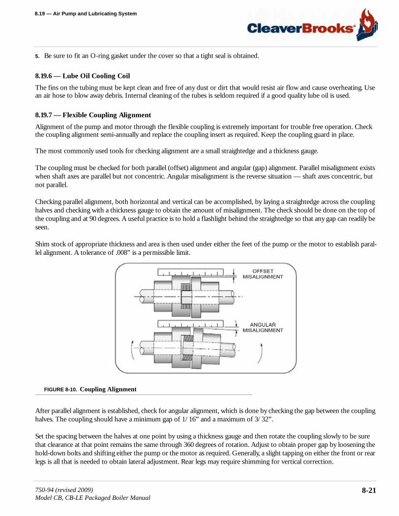
8.19 — Air Pump and Lubricating System
5. Be sure to fit an O-ring gasket under the cover so that a tight seal is obtained.
8.19.6 — Lube Oil Cooling Coil
The fins on the tubing must be kept clean and free of any dust or dirt that would resist air flow and cause overheating. Use an air hose to blow away debris. Internal cleaning of the tubes is seldom required if a good quality lube oil is used.
8.19.7 — Flexible Coupling Alignment
Alignment of the pump and motor through the flexible coupling is extremely important for trouble free operation. Check the coupling alignment semi-annually and replace the coupling insert as required. Keep the coupling guard in place.
The most commonly used tools for checking alignment are a small straightedge and a thickness gauge.
The coupling must be checked for both parallel (offset) alignment and angular (gap) alignment. Parallel misalignment exists when shaft axes are parallel but not concentric. Angular misalignment is the reverse situation — shaft axes concentric, but not parallel.
Checking parallel alignment, both horizontal and vertical can be accomplished, by laying a straightedge across the coupling halves and checking with a thickness gauge to obtain the amount of misalignment. The check should be done on the top of the coupling and at 90 degrees. A useful practice is to hold a flashlight behind the straightedge so that any gap can readily be seen.
Shim stock of appropriate thickness and area is then used under either the feet of the pump or the motor to establish paral-lel alignment. A tolerance of .008” is a permissible limit.
FIGURE 8-10. Coupling Alignment
After parallel alignment is established, check for angular alignment, which is done by checking the gap between the coupling halves. The coupling should have a minimum gap of 1/16” and a maximum of 3/32”.
Set the spacing between the halves at one point by using a thickness gauge and then rotate the coupling slowly to be sure that clearance at that point remains the same through 360 degrees of rotation. Adjust to obtain proper gap by loosening the hold-down bolts and shifting either the pump or the motor as required. Generally, a slight tapping on either the front or rear legs is all that is needed to obtain lateral adjustment. Rear legs may require shimming for vertical correction.
750-94 (revised 2009)Model CB, CB-LE Packaged Boiler Manual
8-21
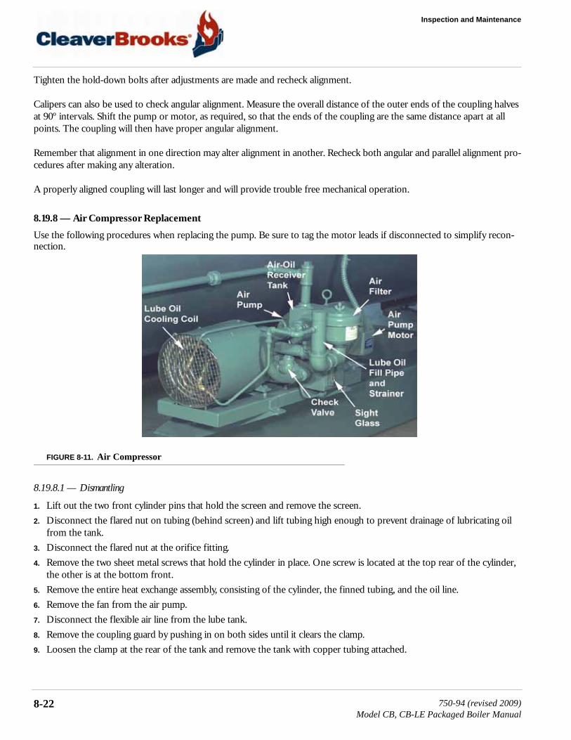
Inspection and Maintenance
Tighten the hold-down bolts after adjustments are made and recheck alignment.
Calipers can also be used to check angular alignment. Measure the overall distance of the outer ends of the coupling halves at 90º intervals. Shift the pump or motor, as required, so that the ends of the coupling are the same distance apart at all points. The coupling will then have proper angular alignment.
Remember that alignment in one direction may alter alignment in another. Recheck both angular and parallel alignment pro-cedures after making any alteration.
A properly aligned coupling will last longer and will provide trouble free mechanical operation.
8.19.8 — Air Compressor Replacement
Use the following procedures when replacing the pump. Be sure to tag the motor leads if disconnected to simplify recon-nection.
FIGURE 8-11. Air Compressor
8.19.8.1 — Dismantling
1. Lift out the two front cylinder pins that hold the screen and remove the screen.2. Disconnect the flared nut on tubing (behind screen) and lift tubing high enough to prevent drainage of lubricating oil
from the tank.3. Disconnect the flared nut at the orifice fitting.4. Remove the two sheet metal screws that hold the cylinder in place. One screw is located at the top rear of the cylinder,
the other is at the bottom front.5. Remove the entire heat exchange assembly, consisting of the cylinder, the finned tubing, and the oil line.6. Remove the fan from the air pump.7. Disconnect the flexible air line from the lube tank.8. Remove the coupling guard by pushing in on both sides until it clears the clamp.9. Loosen the clamp at the rear of the tank and remove the tank with copper tubing attached.
8-22 750-94 (revised 2009)Model CB, CB-LE Packaged Boiler Manual
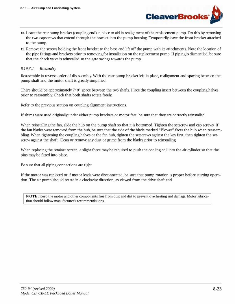
8.19 — Air Pump and Lubricating System
10. Leave the rear pump bracket (coupling end) in place to aid in realignment of the replacement pump. Do this by removing the two capscrews that extend through the bracket into the pump housing. Temporarily leave the front bracket attached to the pump.
11. Remove the screws holding the front bracket to the base and lift off the pump with its attachments. Note the location of the pipe fittings and brackets prior to removing for installation on the replacement pump. If piping is dismantled, be sure that the check valve is reinstalled so the gate swings towards the pump.
8.19.8.2 — Reassembly
Reassemble in reverse order of disassembly. With the rear pump bracket left in place, realignment and spacing between the pump shaft and the motor shaft is greatly simplified.
There should be approximately 7/8” space between the two shafts. Place the coupling insert between the coupling halves prior to reassembly. Check that both shafts rotate freely.
Refer to the previous section on coupling alignment instructions.
If shims were used originally under either pump brackets or motor feet, be sure that they are correctly reinstalled.
When reinstalling the fan, slide the hub on the pump shaft so that it is bottomed. Tighten the setscrew and cap screws. If the fan blades were removed from the hub, be sure that the side of the blade marked “Blower” faces the hub when reassem-bling. When tightening the coupling halves or the fan hub, tighten the setscrews against the key first, then tighten the set-screw against the shaft. Clean or remove any dust or grime from the blades prior to reinstalling.
When replacing the retainer screen, a slight force may be required to push the cooling coil into the air cylinder so that the pins may be fitted into place.
Be sure that all piping connections are tight.
If the motor was replaced or if motor leads were disconnected, be sure that pump rotation is proper before starting opera-tion. The air pump should rotate in a clockwise direction, as viewed from the drive shaft end.
NOTE: Keep the motor and other components free from dust and dirt to prevent overheating and damage. Motor lubrica-tion should follow manufacturer’s recommendations.
750-94 (revised 2009)Model CB, CB-LE Packaged Boiler Manual
8-23
Inspection and Maintenance
8.20 — RefractoryThe boiler is shipped with completely installed refractory. The refractory consists of the rear head, the inner door, and the furnace liner. Normal maintenance requires little time and expense, and prolongs the operating life of the refractory.
FIGURE 8-12. Refractory Liner Tile
Preventive maintenance through periodic inspection will keep the operator informed of the condition of the refractory, and will guard against unexpected and unwanted downtime and major repairs.
Frequent wash coating of the refractory surfaces is recommended. High-temperature bonding, air-dry type mortar, diluted with water to the consistency of light cream, is used for wash coating. Re-coating intervals will vary with operating loads and are best determined by the operator when the boiler is opened for inspection.
8.20.1 — Furnace Liner
Maintenance consists of occasional wash coating of the entire liner. Face all joints or cracks by applying high temperature bonding mortar with a trowel or fingertips. Wash coating should be done as soon as cracks are detected.
Should segments of the liner burn away or fall out, replace the entire refractory. Any refractory that may break out should be removed as soon as detected so that it will not fuse to the bottom of the furnace and obstruct the flame.
If replacement is necessary, refer to Chapter 9 and order proper replacement materials. Remove existing refractory. Thor-oughly clean the furnace to remove all old refractory cement or other foreign material to ensure the new liner seats firmly against the steel. Inspect the furnace metal.
Depending upon the design pressure of the boiler, the furnace may be of the corrugated type. It is necessary to fill in the corrugation valleys under the furnace liner tile from 4 o’clock to 8 o’clock with insulating cement. The liner tile should be fitted tightly against the crown of the corrugation.
NOTE: The area between the burner housing and the throat tile requires a good seal. An improper or poor seal allows air leaks that can cause overheating and burning of the burner housing metal. The area should be inspected semi-annually. Contact your local Cleaver-Brooks representative for information and service.
8-24 750-94 (revised 2009)Model CB, CB-LE Packaged Boiler Manual

8.20 — Refractory
FIGURE 8-13. Refractory Throat Tile
8.20.2 — Throat Tile and Liner Installation
The throat tile must be installed to maintain an approximately 16” inside diameter, and be centered in the furnace. Since the thickness of the furnace metal varies with the boiler design pressure, a shim of appropriate thickness must be used to com-pensate for the variance. A layer or two of insulating board or equal, or a bed of refractory material, may be used to center the ring.
The liner tile can be fitted tightly against the furnace, since the finished diameter is not critical.
FIGURE 8-14. Furnace Liner Refractory
750-94 (revised 2009)Model CB, CB-LE Packaged Boiler Manual
8-25
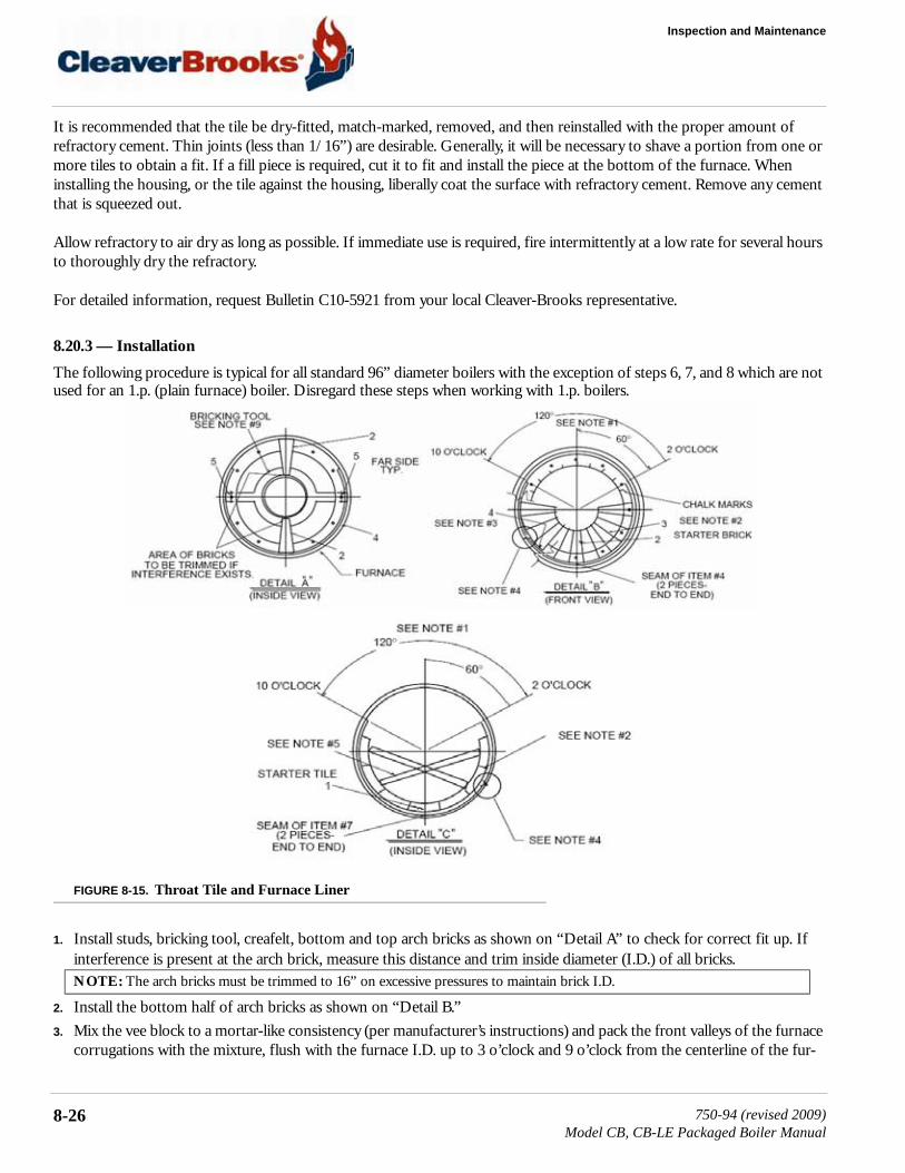
Inspection and Maintenance
It is recommended that the tile be dry-fitted, match-marked, removed, and then reinstalled with the proper amount of refractory cement. Thin joints (less than 1/16”) are desirable. Generally, it will be necessary to shave a portion from one or more tiles to obtain a fit. If a fill piece is required, cut it to fit and install the piece at the bottom of the furnace. When installing the housing, or the tile against the housing, liberally coat the surface with refractory cement. Remove any cement that is squeezed out.
Allow refractory to air dry as long as possible. If immediate use is required, fire intermittently at a low rate for several hours to thoroughly dry the refractory.
For detailed information, request Bulletin C10-5921 from your local Cleaver-Brooks representative.
8.20.3 — Installation
The following procedure is typical for all standard 96” diameter boilers with the exception of steps 6, 7, and 8 which are not used for an 1.p. (plain furnace) boiler. Disregard these steps when working with 1.p. boilers.
FIGURE 8-15. Throat Tile and Furnace Liner
1. Install studs, bricking tool, creafelt, bottom and top arch bricks as shown on “Detail A” to check for correct fit up. If interference is present at the arch brick, measure this distance and trim inside diameter (I.D.) of all bricks.
2. Install the bottom half of arch bricks as shown on “Detail B.”3. Mix the vee block to a mortar-like consistency (per manufacturer’s instructions) and pack the front valleys of the furnace
corrugations with the mixture, flush with the furnace I.D. up to 3 o’clock and 9 o’clock from the centerline of the fur-
NOTE: The arch bricks must be trimmed to 16” on excessive pressures to maintain brick I.D.
8-26 750-94 (revised 2009)Model CB, CB-LE Packaged Boiler Manual

8.20 — Refractory
nace. Install both pieces of cerafelt to insulate the tile from the corrugation and begin bottom half of first row of tiles as shown on “Detail C.”
4. To begin top half of arch bricks and tiles, measure off upper half of furnace arch bricks and tiles with templates, mark with chalk, and determine if a cut brick or cut tile is needed (see “Detail B”). If a cut brick is required, locate it below the 2 o’clock and 10 o’clock positions. If the brick is cut, the angle of the cut surface should be the same as the original brick. If cut brick or tile measures less than 1/2 full width, cut two pieces.
5. Install bricking tool as shown on “Detail A” and continue installing upper half by alternating one arch brick and one cor-responding tile.
6. For the last two rows of tiles, pack all remaining valleys of furnace corrugations (measure 36” from inside surface of arch bricks) with vee block mixture flush with furnace I.D. up to the 3 o’clock and 9 o’clock centerline of the furnace.
7. After joint cement hardens (approximately 2 hours), remove bricking tool, wooden tile supports, and discard cerafelt shims.
8.20.4 — Rear Door
The rear door is a steel shell containing horizontal baffle tiles and lined with insulation material and castable refractory.
Burned or discolored paint on the outer surface of the door does not necessarily indicate refractory trouble, but may be an indication of other conditions such as:
• Leaking gaskets.• Improper seal.• Door retaining bolts insufficiently or unevenly tightened.• The air line to the rear sight tube may be blocked or loose.• Door was repainted with other than heat resistant paint.
Therefore, before assuming that the refractory requires reworking:
INSTALLATION NOTES:
1. No cerafelt, cut bricks, or cut tiles to be installed in the upper 120º section of the furnace. See “Detail A” and “Detail B.”
2. Pack all bricks and tiles tightly with mallet and remove excess cement: 1/16” typical joint, 1/8” maxi-mum.
3. No cement applied between cerafelt and bricks, tiles, or furnace. Only applied between bricks and tiles.
4. Do not cover furnace weld seam with cerafelt. cut and space to suit as shown on “Detail B” and “Detail C.”
5. Support upper tiles with wooden boards to suit assembly. Two boards per tile as shown on “Detail C.” (For 96” diameter, use 3/4” x 1-1/2” x 38”. For 78” diameter, use 3/4” x 1-1/2” x 28”.)
6. To insure tight fit and maximum I.S. of arch bricks, cut a 3” square piece of scrap cerafelt and use as a shim between bricking tool O.D. and I.D. of upper half of bricks.
7. Stagger cemented joints (seams) between all arch bricks and tiles.8. After each half course of bricks or tiles installed, clean up excessive cement and fill open joint areas
where necessary.9. For 78” diameter boilers, use bricking tool #98-d-280 and fasten with two 1/2”-13 nuts. For 96”
boilers, use bricking tool #98-d-279 and fasten with two 5/8”-11 nuts.
750-94 (revised 2009)Model CB, CB-LE Packaged Boiler Manual
8-27

Inspection and Maintenance
• Check the condition of the tadpole gasket and rope seal.• Check for cracks in the castable refractory at ends of the baffle tile.• Check the tightness of the door bolts.• See that the air line to the sight tube is clear, and that the connections are tight. If necessary, blow the line clear with an
air hose.
FIGURE 8-16. Rear Door Sealing
It is normal for refractories exposed to hot gasses to develop thin “hairline” cracks. This is not an indication of improper design or workmanship. Since refractory materials expand and contract with changes in temperature, they should be expected to show minor cracks due to contraction when examined at low temperatures. Cracks to approximately 1/8” across may be expected to close at high temperature. If there are any cracks that are relatively large (1/8” to 1/4” in width), clean and fill them with high-temperature bonding mortar.
If the refractory or blanket insulation require replacement, contact your local Cleaver-Brooks authorized representative.
A good seal between the rear door and the pressure vessel is necessary to prevent leakage of combustion gasses, loss of heat, and to aid in obtaining operating efficiency. Leaks can also cause hot spots that can lead to premature refractory failure and/or damage to the door metal.
8-28 750-94 (revised 2009)Model CB, CB-LE Packaged Boiler Manual

8.20 — Refractory
When opening the door, either for routine maintenance of for an annual inspection, do not do so when the boiler or the door is hot. The refractory will hold its temperature for some time and exposure to ambient temperature or rapid cooling may cause refractory cracking and/or harm to the boiler and door metal.
Before loosening the door bolts, tighten the nut on the davit stud to ensure tension on the davit arm. Putting the davit arm under tension will help eliminate sagging, and will facilitate opening and closing.
The opened door should be supported by blocking or jacking to eliminate possible deformation of the door.
Prior to closing, check all gaskets and sealing surfaces. If the door gasket is hard or brittle, it should be replaced. The fiber-glass ropes used for the baffle seal and for the door gasket seal should not be reused. The door flange and the tube sheet area of the baffle seal should be clean and free of old sealing material, scale, etc. Be sure that all of the gasket retaining fas-teners are in place.
Remove the old rope and insulating cement from the baffle tile or refractory. Be careful not to chip or crack the refractory. The rope is placed in the groove of the monolithic design and on top of the lip of the tile baffle type construction.
Attach a new length of 1-1/4” diameter fiberglass rope (P/N 853-982) to the baffle. Be certain that it is properly positioned and use a rapid setting adhesive (P/N 872-481) to hold it in place.
The area between the curved portion of the sheet and the flange is packed with fiberglass rope and covered with cement to fill the void and to provide a smooth sealing area.
Replacement is not normally necessary, but, if it is, completely remove the old material. Firmly caulk a layer of 1/2” diame-ter rope (P/N 853-996) into the area. Tamp a second layer of 1” diameter rope (P/N 853-999) over the first layer. Apply a coating of insulating cement pulp (P/N 872-26) over the ropes to form a smooth surface. Allow the cement pulp to harden before closing the door.
8.20.5 — Closing and Sealing
Coat the door gasket with an oil and graphite mixture. Apply a small amount of a pulp mixture, consisting of P/N 872-26 cement and water around the inner circumference of the gasket. Press rope into this area. Use 1/2” diameter rope (P/N 853-996) for a boiler of low pressure design. Use 1” diameter rope (P/N 853-999) for a high pressure boiler.
After the rope is installed, the entire rope and gasket area, and the baffle area, should be liberally coated with the pulp mix-ture. When the door is closed, the pulp will compress to protect the tadpole gasket and form a seal between the refractory surface and the tube sheet.
Door bolts should be run in snug and tightened evenly to avoid cocking the door and damaging the gasket. Start tightening at top center and alternate between the top and bottom bolts until both are tight. Do not over tighten. Tighten alternate bolts until the door is secured and gas tight. After the boiler is back in operation, retighten the bolts to compensate for any expansion. Loosen the nut on the davit stud to release tension from the davit arm.
Be certain that the davit arm is under tension before opening. Failure to follow these instructions could result in serious injury or death.
NOTE: A boiler built for high pressure design, such as 150 psi or higher steam or for 60 psi or higher hot water, is constructed with a flanged tube sheet that fits inside the boiler shell and door flange.
! Warning
750-94 (revised 2009)Model CB, CB-LE Packaged Boiler Manual
8-29
Inspection and Maintenance
8.21 — Lubrication
8.21.1 — Electric Motors
Manufacturers of electric motors vary in their specifications for lubrication and care of motor bearings, however, their spe-cific recommendations should be followed.
Ball-bearing equipped motors are pre-lubricated. The length of time a bearing can run without having grease added will depend upon many factors, including the rating of the motor, type of motor enclosure, duty, atmospheric conditions, humidity, and ambient temperatures.
Complete renewal of grease, when necessary, can be accomplished by forcing out the old grease with the new grease:
1. Thoroughly wipe those portions of the housing around the filler and drain plugs (above and below bearings). 2. Remove the drain plug (bottom) and free the drain hole of any hardened grease which may have accumulated. 3. With the motor not running, add new grease through the filler hole until clear grease starts to come out of the drain
hole.4. Before replacing the drain plug, run the motor for 10 to 20 minutes to expel any excess grease. 5. The filler and drain plugs should be thoroughly cleaned before they are replaced.
The lubricant used should be clean and equal to one of the good commercial grades of grease locally available. Some lubri-cants that are distributed nationally are:
• Gulf Oil - Precision Grease No. 2• Humble Oil - Andok B• Texaco - Multifak No. 2• Phillips - 1B + RB No. 2• Fiske Bros. - Ball Bearing Lubricant• Standard/Mobil - Mobilux No. 2
NOTE: Siemens TEFC motors use a different and incompatible grease to those listed above.For Siemens Motors: Contains re-greasable bearings. The shaft end (impeller end) requires the use of CB’s high temperature auto grease system (PN 884-133) for proper lubrication.The opposite shaft end (end opposite impeller) can be greased by the auto grease system or by hand pump, using two or three pumps every three months with a grease compatible with a high temperature aluminum complex grease.
Daily • Check visually for free movement of IFGR linkage.
Quarterly • Manually check for free movement of IFGR linkage.• Inspect and clean IFGR damper (oil-fueled system).• Inspect and clean fan and burner (oil-fueled system).• Grease fan motor.
8-30 750-94 (revised 2009)Model CB, CB-LE Packaged Boiler Manual
8.21 — Lubrication
8.21.2 — Control Linkage
Apply a non-gumming, dripless, high-temperature lubricant, such as graphite or a silicone derivative to all pivot points and moving parts. Work lubricant in well and wipe away excess. Repeat application at regular intervals to maintain freedom of motion of parts.
8.21.3 — Solenoid and Motorized Valves
Solenoid valves and motorized valves require no lubrication.
8.21.4 — IFGR Lubrication
Motors should be lightly lubricated at startup.
1. Disconnect and lock out electrical power to the boiler.2. Wipe clean all grease fittings (fill and drain fittings).3. Remove the fill and drain plugs from the motor end cap.4. Free the drain hole of any hard grease (if necessary, use a piece of wire).5. Add grease using a low-pressure grease gun.
6. With the fill and drain plugs still removed, apply electric power to the boiler, start the motor, and let it run for approxi-mately 30 minutes.
7. Turn the boiler off.
8. Disconnect and lock out electrical power to the boiler. 9. Wipe excess grease from the motor, and install the fill and drain plugs. The motor is ready for operation.10. Reconnect electrical power.
Semi-Annually • Inspect and clean IFGR damper (gas-fueled system).• Inspect and clean fan and burner (gas-fueled system).• Open motor/fan cassette to check for free movement of IFGR linkage
and damper assembly.Annually • Inspect fan impeller.
• Check emissions.• Change inlet gasket.
Disconnect and lock out electrical power to the boiler before lubricating the fan motor. Failure to follow these instructions could result in serious injury or death.
NOTE: The amount and type of grease is very important. Only enough grease should be added to replace the grease used by the bearing. Either too much or too little grease can be harmful. The grease cavity should be filled 1/3 to 1/2 full, using Chev-ron SRI 2 grease or equivalent. Shell Dolium R is a suitable substitute lubricant.
Disconnect and lock out electrical power to the boiler before lubricating the fan motor. Failure to follow these instructions could result in serious injury or death.
! Warning
! Warning
750-94 (revised 2009)Model CB, CB-LE Packaged Boiler Manual
8-31

Inspection and Maintenance
8.22 — Oil Heater: Electric, Steam, Hot WaterAn annual maintenance of the heaters consists primarily of removing the heating element from the shell and scraping any accumulation of carbonized oil or sludge deposits that may have collected on the heat exchanging surfaces.
Before breaking any of the electrical connections to the electric heating elements, mark all wires and terminals to assure rapid and correct replacement of wires.
Finish the cleaning process with a cleaning solvent to cut all hardened deposits from the heater element. Because of the insulating effect of carbon and sludge, periodic cleaning is necessary to prevent overheating of the elements. If operation of the heater becomes sluggish, examine the elements at once and clean as required.
Inspect the shell or tank each time the heater is removed. Flush all accumulated sludge and sediment from the tank before reinstalling the heater.
The condensate from steam oil heaters must be safely discharged to waste. The waste should be checked periodically for any traces of oil that would indicate leaking tubes within the heater.
The hot water oil heater contains a heat transfer solution. Oil flows through an inner tube while boiler water surrounds the outer tube. The space between the two tubes is filled with the heat transfer solution and is connected to an expansion chamber on the rear of the heater. A visual indicator on the chamber reveals the presence of any oil if an oil leak occurs.
A 50/50 solution of permanent antifreeze and water is generally used as the heat transfer solution. If there is no danger of freezing, plain water may be used as a replenishment if necessary to refill.
Evidence of oil in either the steam heater condensate or in the water heater indicator demands prompt repairs.
8.23 — CombustionThe frequency of burner adjustments depends upon several factors, including type of burner, type of fuel, load conditions, ambient temperature, climatic variables, and general maintenance practices.
The air-fuel ratio should be checked monthly in order to alert the operator to losses in efficiency, which do not produce vis-ible flame change. Any time maintenance is performed on the burner linkage, the air-fuel ratio should be checked. Readjust-ment of the burner may be required due to variations in fuel composition. A combustion analyzer should be used to adjust air-fuel ratio for maximum operating efficiency. If your burner requires adjustments, contact your local Cleaver-Brooks authorized representative for assistance.
8-32 750-94 (revised 2009)Model CB, CB-LE Packaged Boiler Manual

8.24 — Recommended Boiler Inspection Schedule
8.24 — Recommended Boiler Inspection Schedule
Daily Monthly Semi-Annually Annually
• Check water level• Check combustion visu-
ally• Blow down boiler• Blow down water col-
umn• Record feedwater pres-
sure/temperature• Record flue gas tempera-
ture• Record oil pressure and
temperature• Record gas pressure• Treat water according to
the established program• Record atomizing air
pressure
• Inspect burner• Inspect for flue gas leak• Inspect for hot spots• Check cams• Check for tight closing
of fuel valve• Check fuel and air link-
age• Check indicating lights
and alarms• Check operating and
limit controls• Check safety and inter-
lock controls• Check for leaks, noise,
vibration, unusual condi-tions, etc.
• Check low water cutoff operation
• Clean low water cutoff• Clean oil pump strainer,
filter• Clean air cleaner and
air/oil separator• Inspect refractory• Remove and clean oil
preheater• Check air pump cou-
pling alignment• Inspect/repair burner
housing to refractory seal
• Clean fireside surfaces• Clean breeching• Inspect waterside sur-
faces• Check operation of
safety valves
750-94 (revised 2009)Model CB, CB-LE Packaged Boiler Manual
8-33

Inspection and Maintenance
8-34 750-94 (revised 2009)Model CB, CB-LE Packaged Boiler Manual

CHAPTER 9 Parts Lists and Drawings
9.1 — Ordering PartsFurnish complete information when ordering parts by giving the item number, description, and the quantity of parts desired, together with the complete nameplate data, including all electrical requirements.
Repair and replacement parts should be ordered from your local Cleaver-Brooks authorized representative.
750-94 (revised 2009)Model CB, CB-LE Packaged Boiler Manual
9-1

Parts Lists and Drawings
9.2 — Parts
9.2.1 — Air Compressor and Piping
9-2 750-94 (revised 2009)Model CB, CB-LE Packaged Boiler Manual

9.2 — Parts
9.2.2 — Air Compressor
750-94 (revised 2009)Model CB, CB-LE Packaged Boiler Manual
9-3

Parts Lists and Drawings
9.2.3 — Air Line Piping
9-4 750-94 (revised 2009)Model CB, CB-LE Packaged Boiler Manual

9.2 — Parts
9.2.4 — Alstrom Heater
750-94 (revised 2009)Model CB, CB-LE Packaged Boiler Manual
9-5
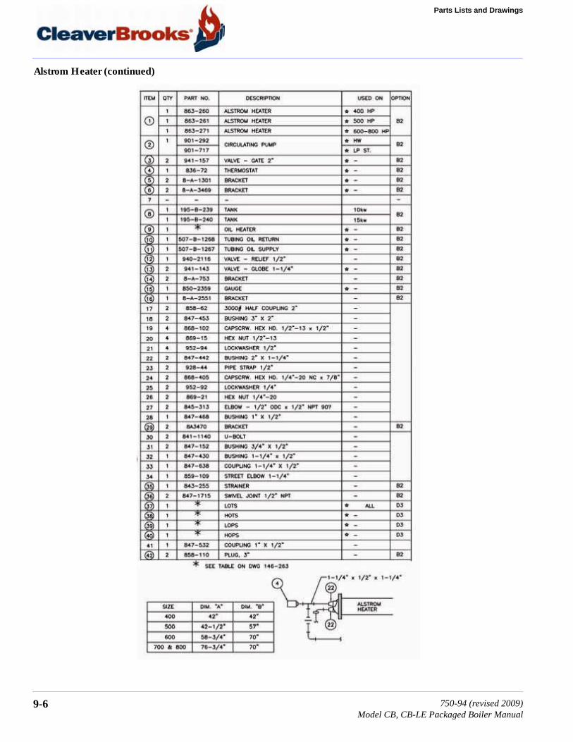
Parts Lists and Drawings
Alstrom Heater (continued)
9-6 750-94 (revised 2009)Model CB, CB-LE Packaged Boiler Manual

9.2 — Parts
9.2.5 — Burner Housing Support
750-94 (revised 2009)Model CB, CB-LE Packaged Boiler Manual
9-7

Parts Lists and Drawings
Burner Housing Support (continued)
9-8 750-94 (revised 2009)Model CB, CB-LE Packaged Boiler Manual
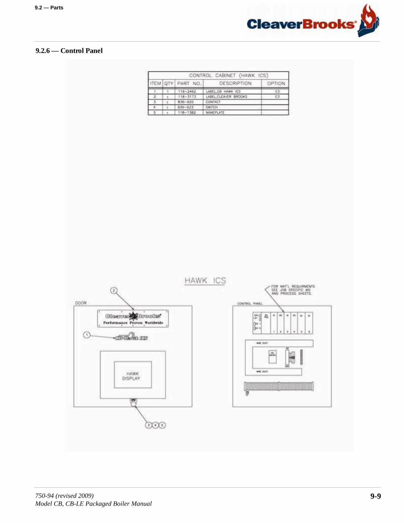
9.2 — Parts
9.2.6 — Control Panel
750-94 (revised 2009)Model CB, CB-LE Packaged Boiler Manual
9-9
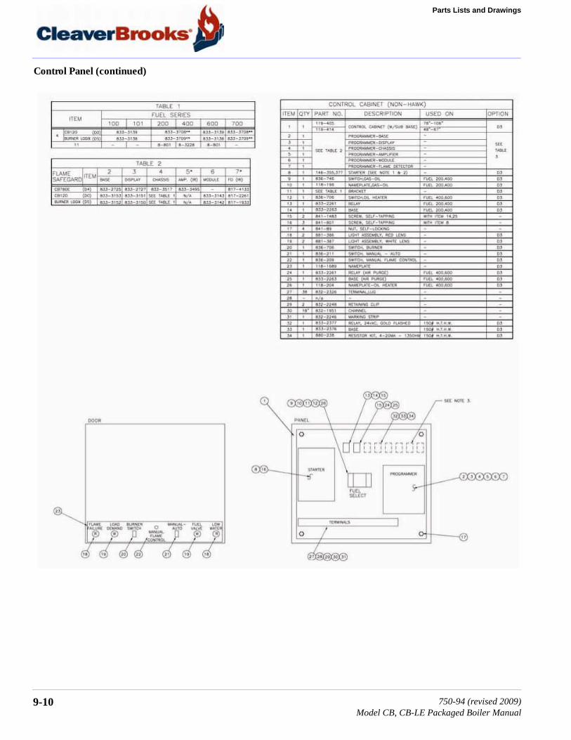
Parts Lists and Drawings
Control Panel (continued)
9-10 750-94 (revised 2009)Model CB, CB-LE Packaged Boiler Manual
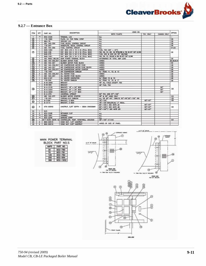
9.2 — Parts
9.2.7 — Entrance Box
750-94 (revised 2009)Model CB, CB-LE Packaged Boiler Manual
9-11

Parts Lists and Drawings
9.2.8 — Front Davit
9-12 750-94 (revised 2009)Model CB, CB-LE Packaged Boiler Manual

9.2 — Parts
9.2.9 — Front Head Linkage
750-94 (revised 2009)Model CB, CB-LE Packaged Boiler Manual
9-13

Parts Lists and Drawings
9.2.10 — Heavy Oil Piping
9-14 750-94 (revised 2009)Model CB, CB-LE Packaged Boiler Manual
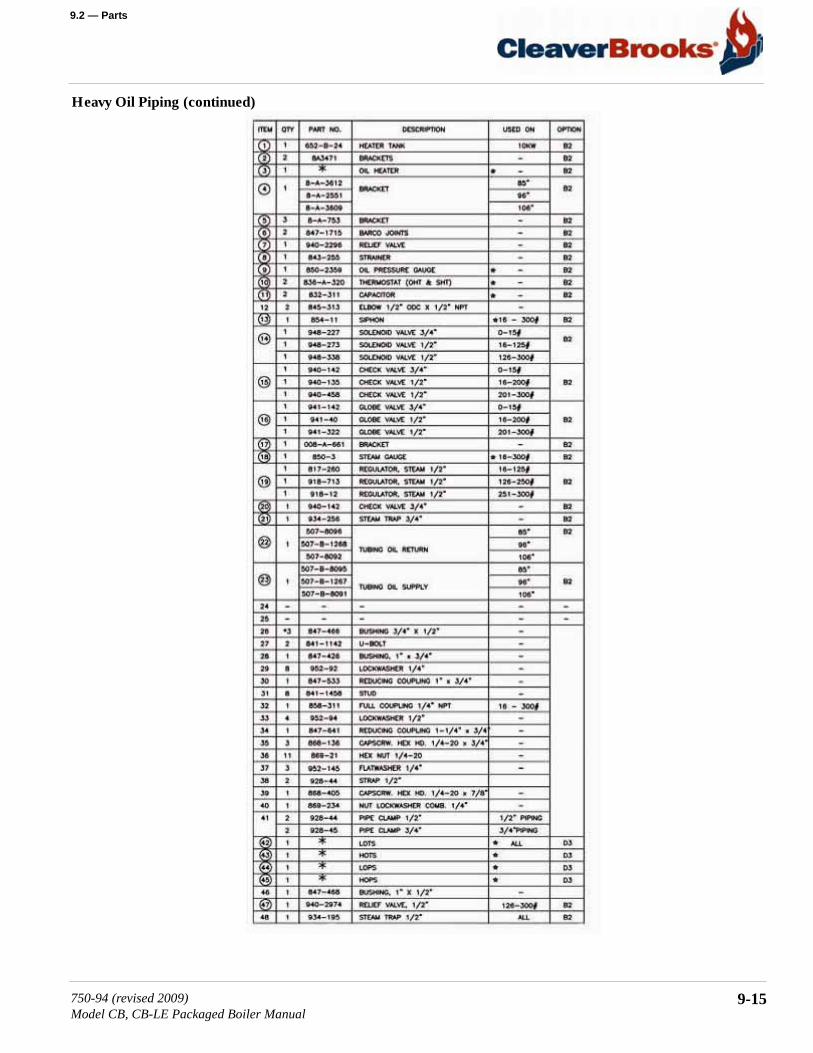
9.2 — Parts
Heavy Oil Piping (continued)
750-94 (revised 2009)Model CB, CB-LE Packaged Boiler Manual
9-15

Parts Lists and Drawings
9.2.11 — Standard Impeller
9-16 750-94 (revised 2009)Model CB, CB-LE Packaged Boiler Manual

9.2 — Parts
9.2.12 — Front Head (Electrical)
750-94 (revised 2009)Model CB, CB-LE Packaged Boiler Manual
9-17
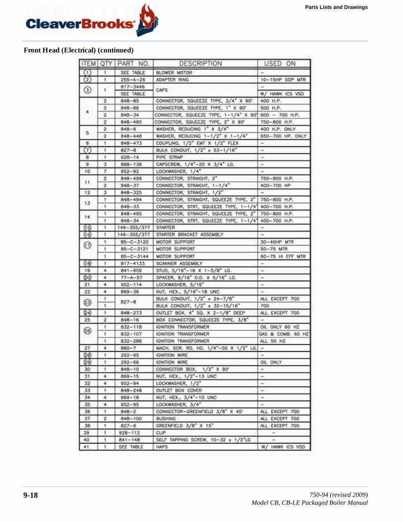
Parts Lists and Drawings
Front Head (Electrical) (continued)
9-18 750-94 (revised 2009)Model CB, CB-LE Packaged Boiler Manual
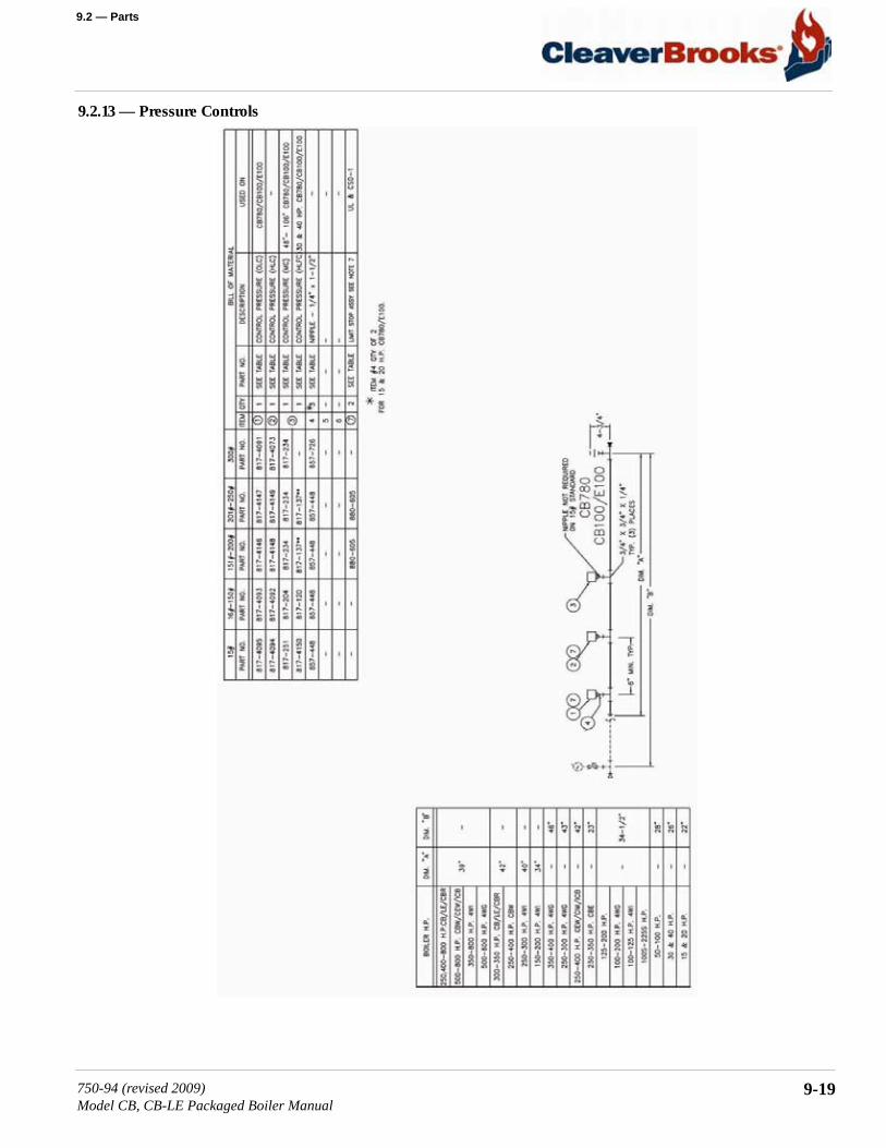
9.2 — Parts
9.2.13 — Pressure Controls
750-94 (revised 2009)Model CB, CB-LE Packaged Boiler Manual
9-19

Parts Lists and Drawings
9.2.14 — Oil/Air Piping, Front Head (Light Oil)
9-20 750-94 (revised 2009)Model CB, CB-LE Packaged Boiler Manual

9.2 — Parts
Oil/Air Piping, Front Head (continued)
750-94 (revised 2009)Model CB, CB-LE Packaged Boiler Manual
9-21
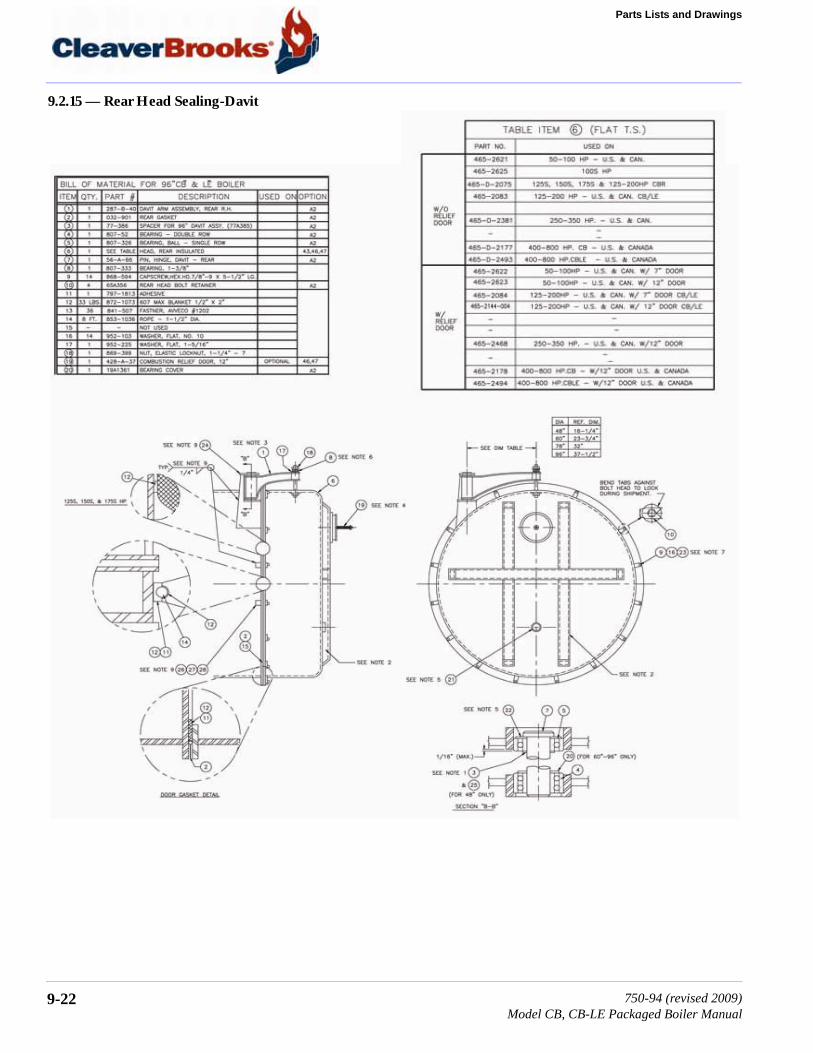
Parts Lists and Drawings
9.2.15 — Rear Head Sealing-Davit
9-22 750-94 (revised 2009)Model CB, CB-LE Packaged Boiler Manual

9.2 — Parts
9.2.16 — Furnace Liner/Bricking
750-94 (revised 2009)Model CB, CB-LE Packaged Boiler Manual
9-23

Parts Lists and Drawings
9.2.16 — Furnace Liner/Bricking (continued)
9-24 750-94 (revised 2009)Model CB, CB-LE Packaged Boiler Manual

9.2 — Parts
9.2.17 — Throat Tile and Furnace Liner
750-94 (revised 2009)Model CB, CB-LE Packaged Boiler Manual
9-25
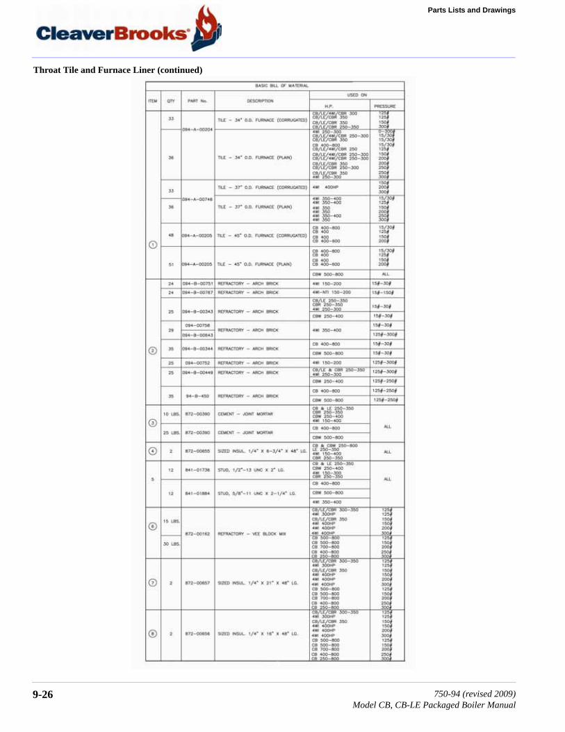
Parts Lists and Drawings
Throat Tile and Furnace Liner (continued)
9-26 750-94 (revised 2009)Model CB, CB-LE Packaged Boiler Manual

9.2 — Parts
9.2.18 — Blower Assembly
750-94 (revised 2009)Model CB, CB-LE Packaged Boiler Manual
9-27

Parts Lists and Drawings
Blower Assembly (continued)
9-28 750-94 (revised 2009)Model CB, CB-LE Packaged Boiler Manual

9.2 — Parts
Blower Assembly (continued)
750-94 (revised 2009)Model CB, CB-LE Packaged Boiler Manual
9-29

Parts Lists and Drawings
9.2.19 — Temperature Controls
9-30 750-94 (revised 2009)Model CB, CB-LE Packaged Boiler Manual
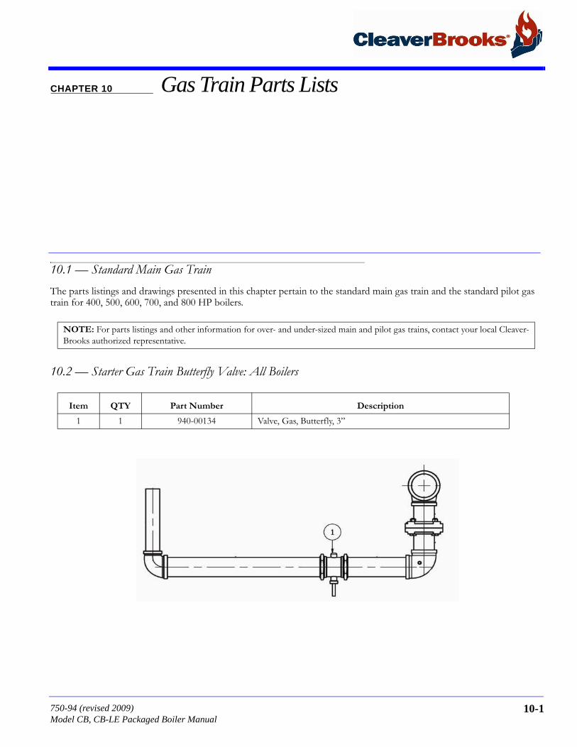
CHAPTER 10 Gas Train Parts Lists
10.1 — Standard Main Gas TrainThe parts listings and drawings presented in this chapter pertain to the standard main gas train and the standard pilot gas train for 400, 500, 600, 700, and 800 HP boilers.
10.2 — Starter Gas Train Butterfly Valve: All Boilers
NOTE: For parts listings and other information for over- and under-sized main and pilot gas trains, contact your local Cleaver-Brooks authorized representative.
Item QTY Part Number Description
1 1 940-00134 Valve, Gas, Butterfly, 3”
750-94 (revised 2009)Model CB, CB-LE Packaged Boiler Manual
10-1

Gas Train Parts Lists
10.3 — Pilot Gas Trains: All Boilers
10.3.1 — Standard & CSD-1 Pilot Gas Train
10.3.2 — NFPA85 Pilot Gas Train
Item QTY Part Number Description
1 1 825-00030 Cock, Gas Service, Tee Head, 1/2” NPT, Bronze2 1 918-00356 Regulator, Gas Pressure, 1/2” NPT, 2-6” WC3 1 850-00109 Gauge, Pressure, 2-1/2”, 0-35” WC, 1/4” NPT Bottom Mount4 1 948-00197 Valve, Solenoid, 1/2” NPT, NC, 0-50 PSI, 150#
Item QTY Part Number Description
1 1 825-00030 Cock, Gas Service, Tee Head, 1/2” NPT, Bronze2 1 918-00356 Regulator, Gas Pressure, 1/2” NPT, 2-6” WC3 1 850-00109 Gauge, Pressure, 2-1/2”, 0-35” WC, 1/4” NPT Bottom Mount4 2 948-00197 Valve, Solenoid, 1/2” NPT, NC, 0-50 PSI, 150#5 1 948-00002 Valve, Solenoid, Gas Vent, 3/4” NPT
10-2 750-94 (revised 2009)Model CB, CB-LE Packaged Boiler Manual

10.4 — Standard Main Gas Trains
10.4 — Standard Main Gas Trains
10.4.1 — 60, 30, &20 PPM Standard Main Gas Train
60, 30, & 20 PPM, 400 HP Standard
60, 30, & 20 PPM, 400 HP W/FM
Item QTY Part Number Description
1 2 941-01947-000 Valve, Butterball, Bronze, 2”, 175 PSI2 1 949-00448-000 Valve Body, Gas, 2”3 1 817-02418-000 LPGS, 12-60” WC Range, MR, 1/4” NPT Mount4 1 945-00238-000 Actuator, Gas Valve, W/O POC5 1 945-00234-000 Actuator, Regulating, W/POC, 6 ”-100” WC6 1 817-02417-000 HGPS, 12-60” Range, MR, 1/4” NPT Mount7 1 941-02640-000 Valve, Ball, Brass, 1/4”, 150#
Item QTY Part Number Description
1 2 941-01947-000 Valve, Butterball, Bronze, 2”, 175 PSI2 1 949-00448-000 Valve Body, Gas, 2”3 1 817-02418-000 LPGS, 12-60” WC Range, MR, 1/4” NPT Mount4 1 945-00236-000 Actuator, Gas Valve, W/POC5 1 945-00234-000 Actuator, Regulating, W/POC, 6 ”-100” WC6 1 817-02417-000 HGPS, 12-60” Range, MR, 1/4” NPT Mount7 1 941-02640-000 Valve, Ball, Brass, 1/4”, 150#
750-94 (revised 2009)Model CB, CB-LE Packaged Boiler Manual
10-3
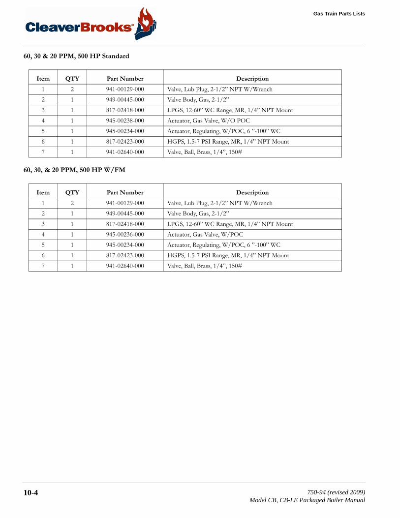
Gas Train Parts Lists
60, 30 & 20 PPM, 500 HP Standard
60, 30, & 20 PPM, 500 HP W/FM
Item QTY Part Number Description
1 2 941-00129-000 Valve, Lub Plug, 2-1/2” NPT W/Wrench2 1 949-00445-000 Valve Body, Gas, 2-1/2”3 1 817-02418-000 LPGS, 12-60” WC Range, MR, 1/4” NPT Mount4 1 945-00238-000 Actuator, Gas Valve, W/O POC5 1 945-00234-000 Actuator, Regulating, W/POC, 6 ”-100” WC6 1 817-02423-000 HGPS, 1.5-7 PSI Range, MR, 1/4” NPT Mount7 1 941-02640-000 Valve, Ball, Brass, 1/4”, 150#
Item QTY Part Number Description
1 2 941-00129-000 Valve, Lub Plug, 2-1/2” NPT W/Wrench2 1 949-00445-000 Valve Body, Gas, 2-1/2”3 1 817-02418-000 LPGS, 12-60” WC Range, MR, 1/4” NPT Mount4 1 945-00236-000 Actuator, Gas Valve, W/POC5 1 945-00234-000 Actuator, Regulating, W/POC, 6 ”-100” WC6 1 817-02423-000 HGPS, 1.5-7 PSI Range, MR, 1/4” NPT Mount7 1 941-02640-000 Valve, Ball, Brass, 1/4”, 150#
10-4 750-94 (revised 2009)Model CB, CB-LE Packaged Boiler Manual

10.4 — Standard Main Gas Trains
10.4.2 — 60, 30, & 20 PPM W/NFPA-85
60, 30, & 20 PPM, 400 HP
60, 30, & 20 PPM, 500 HP
Item QTY Part Number Description
1 2 941-01947-000 Valve, Butterball, Bronze, 2”, 175 PSI2 1 949-00448-000 Valve Body, Gas, 2”3 1 850-02363-000 Gauge, Pressure, 2-1/2”, 0-15 PSI, 1/4” BTM Conn.4 1 817-02418-000 LGPS, 12-60” WC Range, MR, 1/4” NPT Mount5 1 945-00236-000 Actuator, Gas Valve, W/POC6 1 945-00234-000 Actuator, Regulating, W/POC, 6 ”-100” WC7 1 817-02417-000 HGPS, 12-60” WC Range, MR, 1/4” NPT Mount8 1 850-01093-000 Gauge, Pressure, 2-1/2”, 0-100” WC, 1/4” NPT Bottom Mount9 3 941-02640-000 Valve, Ball, Brass, 1/4”, 150#
Item QTY Part Number Description
1 2 941-00129-000 Valve, Lub Plug, 2-1/2” NPT W/Wrench2 1 949-00445-000 Valve Body, Gas, 2-1/2”3 1 850-02363-000 Gauge, Pressure, 2-1/2”, 0-15 PSI, 1/4” Btm. Conn.4 1 817-02418-000 LGPS, 12-60” WC Range, MR, 1/4” NPT Mount5 1 945-00236-000 Actuator, Gas Valve, W/POC6 1 945-00234-000 Actuator, Regulating, W/POC, 6 ”-100” WC7 1 817-02423-000 HGPS, 1.5-7 PSI Range, MR, 1/4” NPT Mount8 1 850-01093-000 Gauge, Pressure, 2-1/2”, 0-100 WC, 1/4” NPT Bottom Mount9 3 941-02640-000 Valve, Ball, Brass, 1/4”, 150#
750-94 (revised 2009)Model CB, CB-LE Packaged Boiler Manual
10-5

Gas Train Parts Lists
10.4.3 — 60, 30, & 20 PPM, 600 HP Standard Main Gas Train
60, 30, & 20 PPM, 600 HP Standard
60, 30, & 20 PPM, 600 HP W/FM
Item QTY Part Number Description
1 1 941-00129-000 Valve, Lub Plug, 2-1/2” NPT W/Wrench2 1 949-00445-000 Valve Body, Gas, 2-1/2”3 1 817-03591-000 LPGS, 1.5-7 PSI Range, MR, 1/4” NPT Mount4 1 945-00238-000 Actuator, Gas Valve, W/O POC5 1 945-00234-000 Actuator, Regulating, W/POC, 6 ”-100” WC6 1 817-02423-000 HGPS, 1.5-7 PSI Range, MR, 1/4” NPT Mount7 1 941-02640-000 Valve, Ball, Brass, 1/4”, 150#8 1 941-00130-000 Valve, Lub Plug, 3” NPT W/Wrench
Item QTY Part Number Description
1 1 941-00129-000 Valve, Lub Plug, 2-1/2” NPT W/Wrench2 1 949-00445-000 Valve Body, Gas, 2-1/2”3 1 817-03591-000 LPGS, 1.5-7 PSI Range, MR, 1/4” NPT Mount4 1 945-00236-000 Actuator, Gas Valve, W/POC5 1 945-00234-000 Actuator, Regulating, W/POC, 6 ”-100” WC6 1 817-02423-000 HGPS, 1.5-7 PSI Range, MR, 1/4” NPT Mount7 1 941-02640-000 Valve, Ball, Brass, 1/4”, 150#8 1 941-00130-000 Valve, Lub Plug, 3” NPT W/Wrench
10-6 750-94 (revised 2009)Model CB, CB-LE Packaged Boiler Manual

10.4 — Standard Main Gas Trains
10.4.4 — 60, 30, & 20 PPM, 600 HP W/NFPA-85
60, 30, & 20 PPM, 600 HP W/NFPA-85
Item QTY Part Number Description
1 1 941-00129-000 Valve, Lub Plug, 2-1/2” NPT W/Wrench2 1 949-00445-000 Valve Body, Gas, 2-1/2”3 1 850-02363-000 Gauge, Pressure, 2-1/2”, 0-15 PSI, 1/4” Btm. Conn.4 1 817-03591-000 LGPS, 1.5-7 PSI Range, MR, 1/4” NPT Mount5 1 945-00236-000 Actuator, Gas Valve, W/POC6 1 945-00234-000 Actuator, Regulating, W/POC, 6 ”-100” WC7 1 817-02423-000 HGPS, 1.5-7 PSI Range, MR, 1/4” NPT Mount8 1 850-01093-000 Gauge, Pressure, 2-1/2”, 0-100 WC, 1/4” NPT Bottom Mount9 3 941-02640-000 Valve, Ball, Brass, 1/4”, 150#10 1 941-00130-000 Valve, Lub Plug, 3” NPT W/Wrench
750-94 (revised 2009)Model CB, CB-LE Packaged Boiler Manual
10-7

Gas Train Parts Lists
10.4.5 — 60, 30, & 20* PPM, 700 & 800 HP Standard Main Gas Train
60, 30, & 20* PPM, 700 & 800 HP Standard
60, 30, & 20* PPM, 700 & 800 HP W/FM
Item QTY Part Number Description
1 2 941-00130-000 Valve, Lub Plug, 3” NPT W/Wrench2 1 949-00446-000 Valve Body, 3”3 1 817-03591-000 LPGS, 1.5-7 PSI Range, MR, 1/4” NPT Mount4 1 945-00238-000 Actuator, Gas Valve, W/O POC5 1 945-00234-000 Actuator, Regulating, W/POC, 6 ”-100” WC6 1 817-02423-000 HGPS, 1.5-7 PSI Range, MR, 1/4” NPT Mount7 1 941-02640-000 Valve, Ball, Brass, 1/4”, 150#
Item QTY Part Number Description
1 2 941-00130-000 Valve, Lub Plug, 3” NPT W/Wrench2 1 949-00446-000 Valve Body, 3”3 1 817-03591-000 LPGS, 1.5-7 PSI Range, MR, 1/4” NPT Mount4 1 945-00236-000 Actuator, Gas Valve, W/POC5 1 945-00234-000 Actuator, Regulating, W/POC, 6 ”-100” WC6 1 817-02423-000 HGPS, 1.5-7 PSI Range, MR, 1/4” NPT Mount7 1 941-02640-000 Valve, Ball, Brass, 1/4”, 150#
10-8 750-94 (revised 2009)Model CB, CB-LE Packaged Boiler Manual

10.4 — Standard Main Gas Trains
10.4.6 — 60, 30, & 20 PPM, 700 & 800 HP Standard Main Gas Train W/NFPA-85
60, 30, & 20* PPM, 700 & 800 HP W/NFPA-86
* There is no 800 HP unit for the 20 PPM boiler.
Item QTY Part Number Description
1 2 941-00130-000 Valve, Lub Plug, 3” NPT W/Wrench2 1 949-00446-000 Valve Body, 3”3 1 850-02363-000 Gauge, Pressure, 2-1/2”, 0-15 PSI, 1/4” Btm. Conn.4 1 817-03591-000 LGPS, 1.5-7 PSI Range, MR, 1/4” NPT Mount5 1 945-00236-000 Actuator, Gas Valve, W/POC6 1 945-00234-000 Actuator, Regulating, W/POC, 6 ”-100” WC7 1 941-02640-000 Valve, Ball, Brass, 1/4”, 150#8 1 850-01093-000 Gauge, Pressure, 2-1/2”, 0-100” WC, 1/4” NPT Bottom Mount9 3 941-02640-000 Valve, Ball, Brass, 1/4”, 150#
750-94 (revised 2009)Model CB, CB-LE Packaged Boiler Manual
10-9

Gas Train Parts Lists
10-10 750-94 (revised 2009)Model CB, CB-LE Packaged Boiler Manual