cltp4 sensor actuator pdf配布用 - uniseccltp4_sensor_actuator.pdf · use case of satellite...
TRANSCRIPT
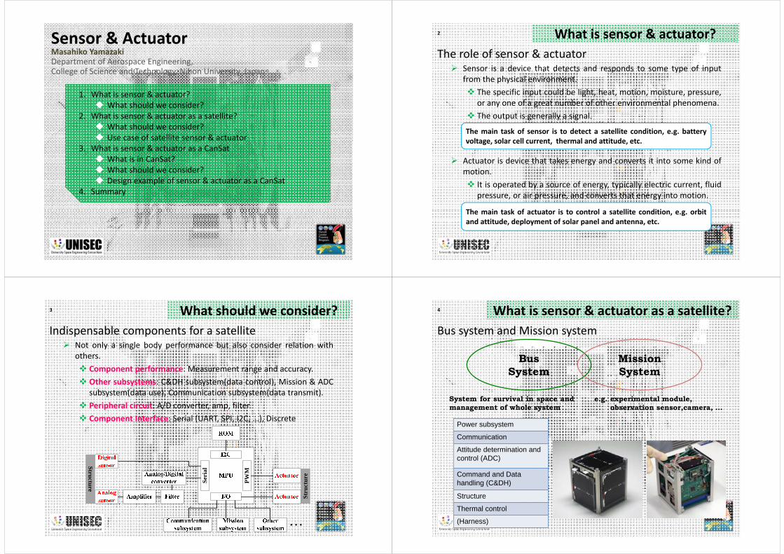
Sensor & ActuatorMasahiko YamazakiDepartment of Aerospace Engineering,College of Science and Technology, Nihon University, Japan
1. What is sensor & actuator? What should we consider?
2. What is sensor & actuator as a satellite? What should we consider? Use case of satellite sensor & actuator
3. What is sensor & actuator as a CanSat What is in CanSat? What should we consider? Design example of sensor & actuator as a CanSat
4. Summary
2 What is sensor & actuator?
Sensor is a device that detects and responds to some type of inputfrom the physical environment. The specific input could be light, heat, motion, moisture, pressure,
or any one of a great number of other environmental phenomena. The output is generally a signal.
Actuator is device that takes energy and converts it into some kind ofmotion. It is operated by a source of energy, typically electric current, fluid
pressure, or air pressure, and converts that energy into motion.
The role of sensor & actuator
The main task of sensor is to detect a satellite condition, e.g. batteryvoltage, solar cell current, thermal and attitude, etc.
The main task of actuator is to control a satellite condition, e.g. orbitand attitude, deployment of solar panel and antenna, etc.
3 What should we consider?
Not only a single body performance but also consider relation withothers. Component performance: Measurement range and accuracy. Other subsystems: C&DH subsystem(data control), Mission & ADC
subsystem(data use), Communication subsystem(data transmit). Peripheral circuit: A/D converter, amp, filter. Component Interface: Serial (UART, SPI, I2C, ...), Discrete
Indispensable components for a satellite
PWM
Seri
al
Structure
Stru
ctur
e4 What is sensor & actuator as a satellite?Bus system and Mission system
Bus System
Mission System
System for survival in space andmanagement of whole system
e.g. experimental module,observation sensor,camera, …
Power subsystem
Communication
Attitude determination and control (ADC)
Command and Data handling (C&DH)
Structure
Thermal control
(Harness)

5
Communication
Receiver Transmitter
Sensor
S1 S2 Sn
voltage, temperature, current, attitude sensors
Command & Data handling
Actuator
ThrusterTorquer
Reaction wheel
Mission Subsystem
SensorExperimental system
Camera etc.
Electrical power supply
Battery
OBC Memory
Uplink Downlink
Solar cell
Solar cell
Structure
Ground Station
UplinkDownlink
What is sensor & actuator as a satellite? What is sensor & actuator as a satellite?6
Ground Station
UplinkDownlink
VoltageTemperatureCurrentMagnetismSun lightAccelerationAngular velocity
Reaction wheelMagnetic torqueNichrome wire
Sensor example
Actuator example
7 What should we consider?
Ground Station
UplinkDownlink
Sensor & Actuator are closely related with C&DH subsystem.― Data communication rate, Sampling interval, Memory size, Control
interval, etc.
8 What should we consider?
Ground Station
UplinkDownlink
Sensor & Actuator are closely related with other subsystemsElectrical power supply, Communication, Structure, Command & datahandling subsystem.― power consumption, data amount(Memory size, sampling interval,
downlink format), operation order, component layout, etc…

9 What should we consider?
-0.4
-0.2
0
0.2
0.4
0.6
0 200 400 600 800 1000 1200
BxByBz
Mag
netic
flux
den
sity
[gau
ss]
Time [sec]
CW started
[Operation order]Magnetic sensor (with radio communication noise)
10 What should we consider?[Components layout]Thermal sensor (Inner and Outer components)
-40-30-20-10
0102030
0 1000 2000 3000 4000 5000 6000 7000
Solar panel 1Solar panel 2Solar panel 3
Solar panel 4Solar panel 5Solar panel 6
Tem
pera
ture
(Cel
sius
)
Time (sec)
Eclipse
Daytime
-40-30-20-10
0102030
0 1000 2000 3000 4000 5000 6000 7000
Li-ion battery #1Gyro # 2
ReceiverDigi-talker
Tem
pera
ture
(Cel
sius
)
Time (sec)
11 What should we consider?[Components layout]Sun sensor (Outer panel of CubeSat)
12+ 0.0- 0.0220.0 [mm]
20100.
+.0
-210.0
[mm]
15148.
+.8
-214.8
[mm]
12 Use case of satellite sensor & actuatorAttitude determination and control subsystem
Attitude determination = determination ofthe directional vector of each body axis
Attitude control = to control the directionalvector to required value
sat sat sat satx y z
é ù= ê úë ûR e e e

13
Attitude determination and control subsystem Attitude determination sensor
For example, extended Kalman filter by using sun sensors, geomagnetic sensors, and gyro sensors
Reference direction
Sensor for attitude
determination
Geomagnetic sensor
Sun sensor
Earth sensor
Star tracker
Attitude motion
Relative position
Angular velocity
Relative angle
Acceleration
GPS receiver
RF sensor
Mechanical gyro
Optical gyro
MEMS gyro
Accelerometer
Position
Field
Use case of satellite sensor & actuator 14
Attitude determination and control subsystem Attitude control actuator
For example, 3 axis control by magnetic torquerInternal force
Attitude control
actuator
External force
Momentum wheel, Reaction wheel
Monopropellant(catalytic hydrazine )
Control moment gyro
Thruster
Bipropellant (oxidizer and fuel)
Gas-liquid equilibrium thruster
Ion engine
Gravity gradient torque Extensible boom
Geomagnetic torque
Aerodynamic drag
Solar radiation pressure
Magnetic torquer
Permanent magnet
Dragshute
Deployable membrane
Cold gas jet
Use case of satellite sensor & actuator
15
Attitude determination and control subsystem Attitude control actuator
For example, 3 axis control by magnetic torquerInternal force
Attitude control
actuator
External force
Momentum wheel, Reaction wheel
Monopropellant(catalytic hydrazine )
Control moment gyro
Thruster
Bipropellant (oxidizer and fuel)
Gas-liquid equilibrium thruster
Ion engine
Gravity gradient torque Extensible boom
Geomagnetic torque
Aerodynamic drag
Solar radiation pressure
Magnetic torquer
Permanent magnet
Dragshute
Deployable membrane
Cold gas jet
Solar sailIKAROS
Use case of satellite sensor & actuator 16
Attitude determination and control subsystem A/D converter, Filter and Amp.
Out
put V
olta
ge (V
) x
yz
Out
put V
olta
ge (V
)
x
yz
Low pass filter for gyro sensor
Use case of satellite sensor & actuator

17
Attitude determination and control subsystem Current control.
Pulse width modulation
Command & Data handling
OBCMemoryData storage
Actuator
ActuatorCurrent control
(PWM, Motor driver)
Control input(digital signal)
Pulse width modulation(PWM) Pulse Width Modulation is a
simple method for controllinganalog devices via a digital signal.It’s a very efficient way to drivemotors.
Use case of satellite sensor & actuator
Command & Data handling
OBCMemoryData storage
Sensor
Galvanometer
Output voltage(Analog signal)Amp
Filter
AD convertor
Command(Digital signal)
Output voltage(Digital signal)
Actuator
Magnetic Torquer
Current control(PWM, Motor driver)
Control input
Gyro 3axis
18
Attitude determination and control subsystem Ex. De-spin control by Magnetic Torquer
Use case of satellite sensor & actuator
19 What should we consider?
Ground Station
UplinkDownlink
Sensor & Actuator are closely related with other subsystems (Electricalpower supply, Communication, Structure, Command & Data handling) andaffected each other.― power consumption, data amount(Memory size, sampling interval,
downlink format), operation order, component layout, etc…
It is important to extract performance as a system.
It is important to consider the interference between sub-systems
The mission sequence should be imaged well, discussed, and should beshared well in the team.
CanSat?
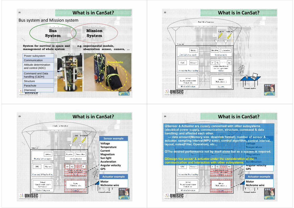
21 What is in CanSat?Bus system and Mission system
Bus System
Mission System
System for survival in space andmanagement of whole system
e.g. experimental module,observation sensor, camera, …
Power subsystemCommunicationAttitude determination and control (ADC)
Command and Data handling (C&DH)StructureParachute(Harness)
Parachute
22 What is in CanSat?
23 What is in CanSat?
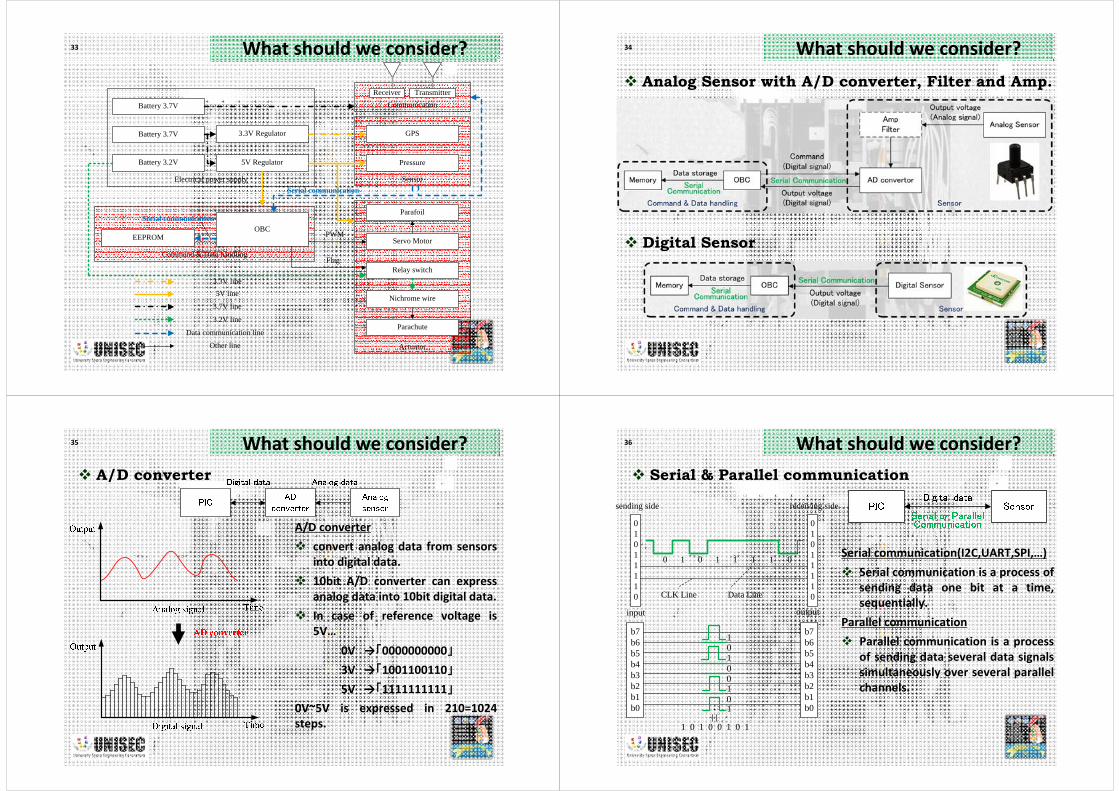
VoltageTemperatureCurrentMagnetismSun lightAccelerationAngular velocityGPS
MotorNichrome wire
Sensor example
Actuator example
24 What is in CanSat?
VoltageTemperatureCurrentMagnetismSun lightAccelerationAngular velocityGPS
MotorNichrome wire
Sensor example
Actuator example
Sensor & Actuator are closely concerned with other subsystems (electrical power supply, communication, structure, command & data handling) and affected each other.― data amount(Memory size, downlink format), number of sensor &
actuator, sampling interval(MPU spec), control algorithm, control interval, layout, noise(Filter, Operation), etc…
The desired performance not by itself alone but as a system is required.
Design the sensor & actuator under the consideration of the communication and interaction with other subsystems.

25 What should we consider?
Separation
Autonomous Flight
Launch Ground stationObjective point
Downlink
Uplink
26 What should we consider?
Separation
Autonomous Flight
Launch Ground stationObjective point
Downlink
Uplink
The mission sequence should be imaged well, discussed, and should be shared well in the team.
Imagine all the possible events and anomalies which may happen on CanSat and prepare countermeasures for them as many as possible.
27 What should we consider?
Separation
Autonomous Flight
Launch Ground stationObjective point
Downlink
Uplink
Step1:Sensor and Actuator selection
Consider requirement(weight, dimension), environmental condition(vibration, acceleration, thermal), flight time, etc…from past experience
Consider Mission Sequence & clarify requirements(1) Set up CanSat and put it into a rocket and turn on switch A.
(2) Rocket side prepare launch(you cannot contact and not predict the time)
(3) Launch with high acceleration(CanSat may measure something in a rocket and write in memory)
(4) CanSat Starts certain operation triggered by some switch at the timing of release from the rocket.
(5) Downlink mission data as well as write in memory.
(6) Landing may trigger also another actions….
28 What should we consider?
Sensoring: to be detected considering what kind of sensors are available and how easy to implement―Temperature, Pressure, GPS, Accelerometer, Sun light, Gyro, Ultra violet, Sound, Infra red,…
Actuation: available actuators, power, force, etc…―Motor, Nichrome line to cut nylon wire, Magnet, Utilization of shock of landing, Spring, Gravity,…
High level actions: combination of sensor, actuator & other systems―Guidance/control with GPS(comeback), camera, stand up, moving a er landing,…
Step1:Sensor and Actuator selectionWhat kind of sensors & actuator are available. How easy to implement―Spec(How accurate?, How often?), Environmental tolerance, Powerconsumption, Data form(Digital/Analog) and Interface(I2C, Serial, UART),Size, Weight, Operating voltage… )

29 What should we consider?
Direction control start!
Mission Example
Parachute separation!
30 What should we consider? Mission Example
Release from the Rocket
Launch!
Parachute deployment
Power ON
Save sensor data(GPS & Pressure)
Altitude <=1600ftParachute release
(Pressure & Nichrome wire)
Parafoildeployment
Direction control(Servo Motor & GPS)
Landing
Parachute separation!
Direction control start!
31 What should we consider? Mission Example
Release from the Rocket
Launch!
Parachute deployment
Power ON
Save sensor data(GPS & Pressure)
Altitude <=1600ftParachute release
(Pressure & Nichrome wire)
Parafoildeployment
Direction control(Servo Motor & GPS)
Landing
32 What should we consider?
Electrical power supply
Actuator
Sensor
Command & Data handling
OBCEEPROM Servo Motor
GPS
Relay switch
Nichrome wire
Battery 3.7V
5V Regulator
3.3V Regulator
Parafoil
Battery 3.2V
Parachute
5V line
Data communication line
Other line
Pressure
3.2V line
Battery 3.7V CommunicationReceiver Transmitter
3.7V line
PWM
Flag
Serial communication
Serial communication
3.3V line
33 What should we consider?
Electrical power supply
Actuator
Sensor
Command & Data handling
OBCEEPROM Servo Motor
GPS
Relay switch
Nichrome wire
Battery 3.7V
5V Regulator
3.3V Regulator
Parafoil
Battery 3.2V
Parachute
Pressure
Battery 3.7V CommunicationReceiver Transmitter
PWM
Flag
Serial communication
Serial communication
5V line
Data communication line
Other line
3.2V line
3.7V line
3.3V line
34 What should we consider? Analog Sensor with A/D converter, Filter and Amp.
Digital Sensor
35 What should we consider? A/D converter
A/D converter convert analog data from sensors
into digital data. 10bit A/D converter can express
analog data into 10bit digital data. In case of reference voltage is
5V…0V →「0000000000」3V →「1001100110」5V →「1111111111」
0V~5V is expressed in 210=1024steps.
36 What should we consider? Serial & Parallel communication
01011110
01011110
0 1 0 1 1 1 1 0
sending side receiving side
CLK Line Data Line
b7b6b5b4b3b2b1b0
b7b6b5b4b3b2b1b0
input output
1
0
0
0
1
01
1
1 0 1 0 0 1 0 1
Serial communication(I2C,UART,SPI,…) Serial communication is a process of
sending data one bit at a time,sequentially.
Parallel communication Parallel communication is a process
of sending data several data signalssimultaneously over several parallelchannels.
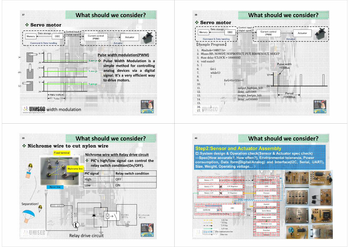
37 What should we consider? Servo motor
Pulse width modulation
Pulse width modulation(PWM) Pulse Width Modulation is a
simple method for controllinganalog devices via a digitalsignal. It’s a very efficient wayto drive motors.
38 What should we consider? Servo motor
【Sample Program】 1. #include<16f877.h> 2.#fuses HS, NOWDT, NOPROTECT, PUT, BROWNOUT, NOLVP 3.#use delay (CLOCK = 10000000) 4.void main() 5.{ 6. int i; 7. while(1) 8. { 9. for(i=0;i<10;i++) 10. { 11. output_high(pin_b3); 12. delay_us(1500); 13. output_low(pin_b3); 14. delay_us(16500); 15. } 16. } 17.}
V+
0V
Pulse width =1500us
Period=18000us
39 What should we consider? Nichrome wire to cut nylon wire
+3.2V
D1DIODE
+
-VcSW1STTL
PIC in
+V5V
Q1PNP
WireNichromR2
1k
Relay drive circuit
PIC signal Relay switch condition
High OFF
Low ON
Nichrome wire with Relay drive circuit PIC’s high/low signal can control the
relay switch condition(On/OFF).
Separation!
40 What should we consider?Step2:Sensor and Actuator Assembly:System design & Operation check(Sensor & Actuator spec check)―Spec(How accurate?, How often?), Environmental tolerance, Power consumption, Data form(Digital/Analog) and Interface(I2C, Serial, UART),Size, Weight, Operating voltage… )
Electrical power supply
Actuator
Sensor
Command & Data handling
OBCEEPROM Servo Motor
GPS
Relay switch
Nichrome wire
Battery 3.7V
5V Regulator
3.3V Regulator
Parafoil
Battery 3.2V
Parachute
Pressure
Battery 3.7V CommunicationReceiver Transmitter
PWM
Flag
Serial communication
Serial communication
5V line
Data communication line
Other line
3.2V line
3.7V line
3.3V line
41 What should we consider?
Structure
Electrical power supply
Actuator
Sensor
Command & Data handling
OBCEEPROM Servo Motor
GPS
Relay switch
Nichrome wire
Battery 3.7V
5V Regulator
3.3V Regulator
Parafoil
Battery 3.2V
Parachute
Pressure
Battery 3.7V CommunicationReceiver Transmitter
PWM
Flag
Serial communication
Serial communication
5V line
Data communication line
Other line
3.2V line
3.7V line
3.3V line
42 What should we consider?
Electrical power supply
Actuator
Sensor
Command & Data handling
OBC(PIC16F877)EEPROM Servo Motor
(S3102)
GPS(CCA-552JZ)
Relay switch
Nichrome wire
Battery 3.7V
5V Regulator
3.3V Regulator
Parafoil
Battery 3.2V
Parachute
5V line
Data communication line
Other line
Pressure(PSM001/2KPG)
3.2V line
Battery 3.7V Communication
Receiver Transmitter
3.7V line
PWM
Flag
Step3:Sensor and Actuator Integration & TestAssemble sensor & actuator with other subsystem as a CanSat.
Integration is carried out taking into consideration the problem which may arise at the time of integration. ―Power consumption, layout, algorithm, operation sequence, interference.
Try as many ground test as possible in various settings to ensure normal operation of CanSat.
Test is carried out to ensure normal operation of CanSat.―Integrated testing(performance check as a CanSat), Environmental Testing(thermal, vibration, etc), Calibration, Operation Testing
Satellite or CanSat cannot always be experimented or confirmed under the circumstance that is similar to the real one.
Results of number of experiments and confirmation tests are connected in order to build a trustworthy system.
43 What should we consider?
3
3.2
3.4
3.6
3.8
4
4.2
4.4
0 5000 10000 15000 20000 25000
Main Battery
Servo Battery
Waiting for launch
Servo system is ON(1hour)
Voltage
[V]
Time [sec]
Electric power verification Test
Release from the Rocket
Launch!
Parachute deployment
Power ON
Save sensor data(GPS & Pressure)
Altitude <=16000ftParachute release
(Pressure & Nichrom wire)
Parafoildeployment
Direction control(Servo Motor & GPS)
Landing
44 What should we consider? Control Algorithm & Ground test
East longitude [deg.]
North latitud
e [deg.]
Direction of movement
(GPS)Neutral
Right small turn
Right large turn Left large turn
Left small turn
Objective point

45 What should we consider? Parafoil performance test
Wind-tunnel test
Flight Test
46 What should we consider? Interference
GPS-MPU
GPSRadio shielding sheet
47 What should we consider? Interference
Communication-Sensor
-0.4
-0.2
0
0.2
0.4
0.6
0 200 400 600 800 1000 1200
BxByBz
Mag
netic
flux
den
sity
[gau
ss]
Time [sec]
CW started
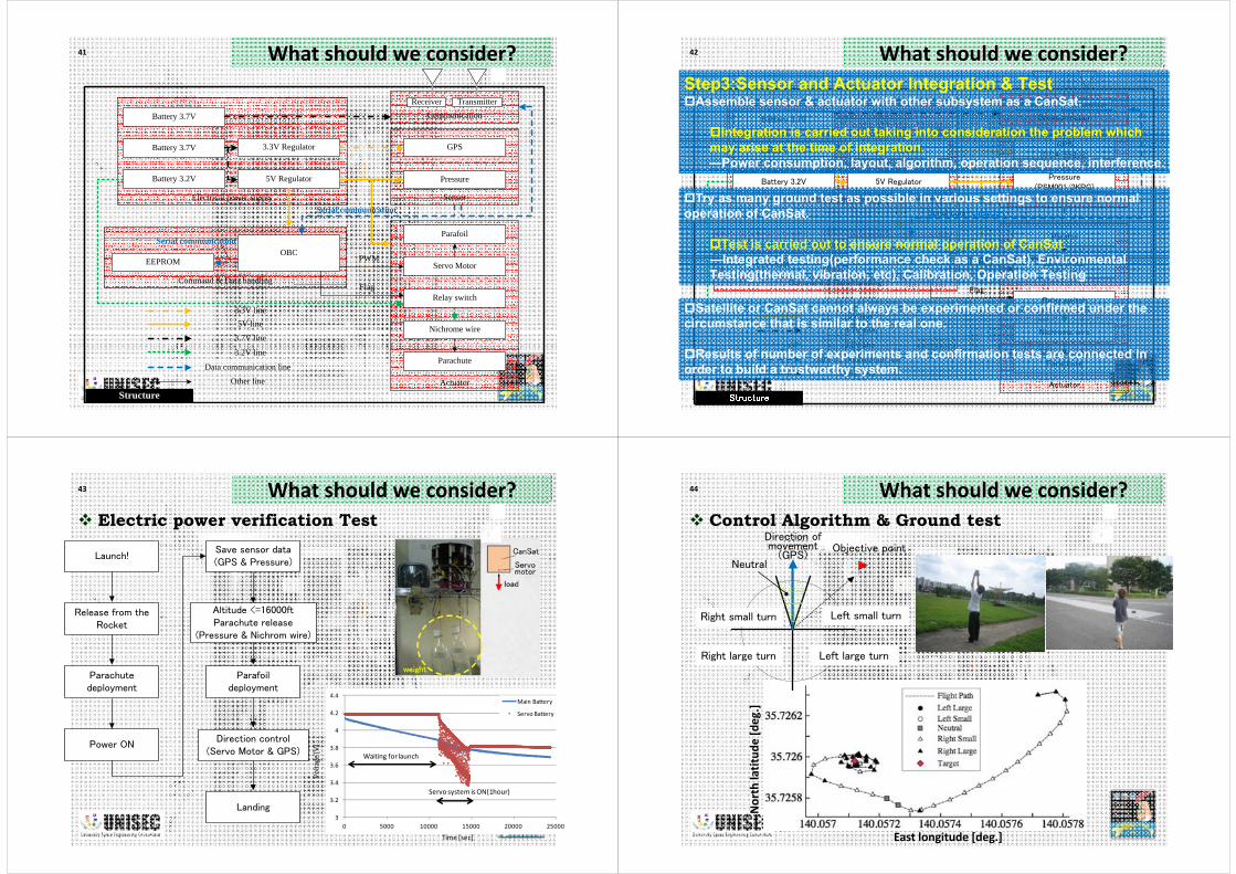
48 What should we consider?
48
Balloon experiment
OPEN
Reel
CanSat
Balloon
100~150m
Ground Station
49 What should we consider? Balloon experiment
East longitude [deg.]
North latitud
e [deg.]
50 What should we consider? Balloon experiment
East longitude [deg.]
North latitud
e [deg.]
Step1:Sensor and Actuator selectionWhat kind of sensors & actuator are available. How easy to implement―Spec(How accurate?, How often?), Environmental tolerance, Power
consumption, Data form(Digital/Analog), Size, Weight, Operatingvoltage… )
Step2:Sensor and Actuator AssemblyStep3:Sensor and Actuator Integration & TestPower consumption, layout, algorithm, operation sequence, interference,Integrated testing(performance check as a CanSat), EnvironmentalTesting(thermal, vibration, etc), Calibration, Operation Testing
・Imagine the flight as completely as possible!
・It is important to consider the interference between sub-systems.
・Confirm the sequence of the mission, and check the validity of the sensordata and the actuator motion, the success of the communication, the powerconsumption of the batteries, and so on.
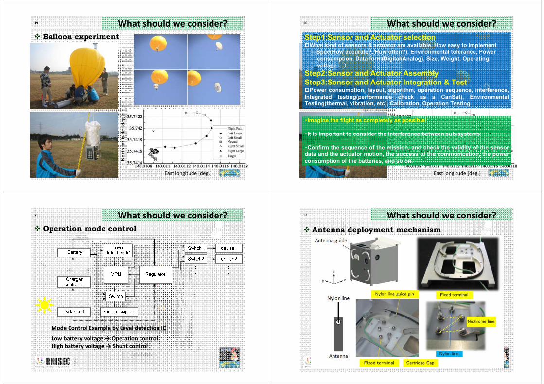
51 What should we consider? Operation mode control
Mode Control Example by Level detection IC
Low battery voltage → Operation controlHigh battery voltage → Shunt control
52 What should we consider? Antenna deployment mechanism

53 What should we consider? Sun sensor
For example, our SPROUT mounts 6 sun sensors
Sun sensorPinhole
Hood
Position Sensitive Detector
54 What should we consider? Sun sensor(using solar cell current)
55 What should we consider? Calibration
56 What should we consider? Manufacturing
Bearing
Bearing Torque rod
Coil wire
Slide rail

57 What should we consider? CanSat for CubeSat
Mission ObjectiveAssembly, integration & test of part of CubeSat(Sensor, Data communication, Data save)Mission sequence simulation of part of CubeSat
Summary
I think, The main task of sensor is to detect a satellite condition, e.g. battery
voltage, solar cell current, thermal and attitude, etc. The main task of actuator is to control a satellite condition, e.g. orbit
and attitude, deployment of solar panel and antenna, etc. Imagine the flight as completely as possible!
In this lecture, I talked about Role of sensor and actuator. Design example of satellite and CanSat sensor and actuator subsystem.