cma serie - bernier
TRANSCRIPT
Release 2.0 - JUIN 2016 www.bernier.tm.fr
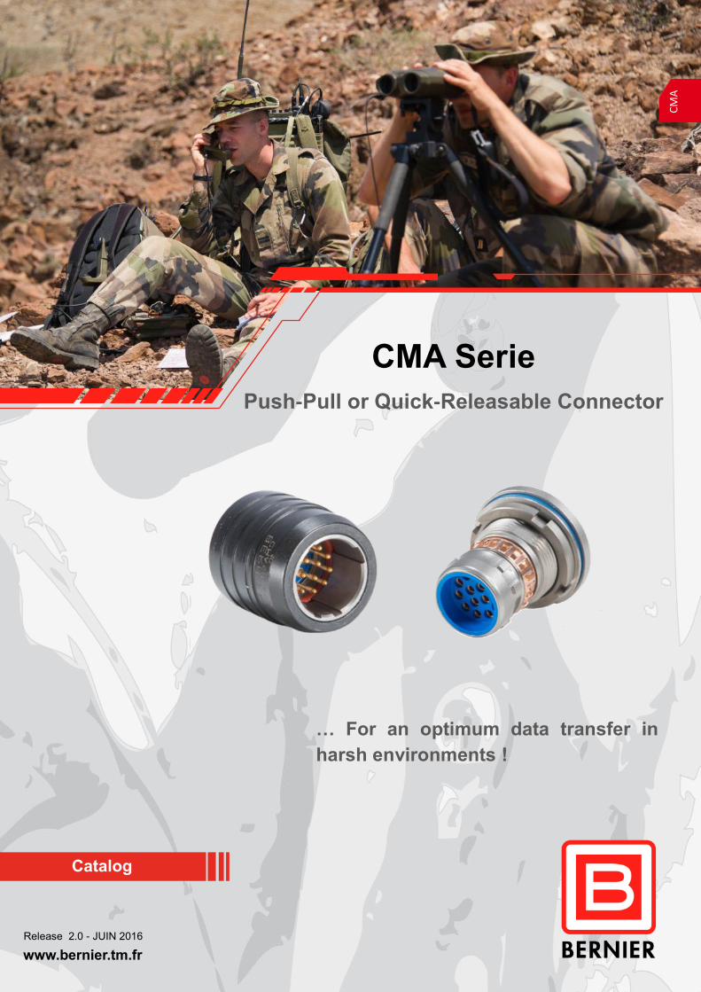
CMA Serie
Push-Pull or Quick-Releasable Connector
Catalog
… For an optimum data transfer in
harsh environments !
CM
A

Page 2 CMA Serie– Release 2.0—JUNE 2016
CM
A
Description
Applications
Introduction
BERNIER designed the CMA line specially for equipment in harsh environments. The CMA connectors are avai-
lable equipped with 04, 06, 10, 14 and 22 contacts, their toughness and ergonomics are apreciated in a wide
range of applications.
Future soldier
Accessories Intercoms Crypted data
Optronic devices
Radios
Ruggedized computers
Tactical equipements
Push-Pull
Stainless steel EMI RFI Protection
Watertightness
Ergonomics
Multi-Contacts

CMA Serie– Release 2.0 - JUNE 2016 Page 3
CM
A
Specific Designs
The Right Solution for your projects
Conductive O rings Ground pin
EMC reinforcements
Ground ring « 360° »
CMA standard receptacles are
equipped with a ground ring giving
a high EMC level. This function
developed by Bernier brings a
better continuity between the con-
nectors shells and a protection on
360°
CMA connectors are appreciated for their flexibility to fit customer specifications.
Our Design team is able to propose versions answering to your needs. Reinforcements can be applied in
case of use in harder climatic, ergonomic and electromagnetic conditions.
The CMA line evolution led by BERNIER has come to integrate electronic modules in the connector shell
to carry wireless functions or to make adaptators towards other industrial or military connectors.
Caps and backshells can also be improved to bring a better ergonomics on your configuration.
The receptacle Fluorosilicon
Oring can be switched to a
conductive version to establish
a better conductivity between
the connector and the panel.
One or several ground pins
inserted in the connector shell
can be set to link the chassis
ground directly to the PCB.
Options are available in order to reinforce the EMC specifications.
Page 4 CMA Serie– Release 2.0—JUNE 2016
CM
A
Technical data
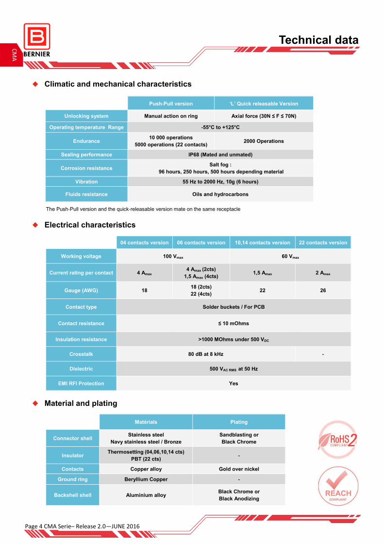
Climatic and mechanical characteristics
Electrical characteristics
Push-Pull version ‘L’ Quick releasable Version
Unlocking system Manual action on ring Axial force (30N ≤ F ≤ 70N)
Operating temperature Range -55°C to +125°C
Endurance 10 000 operations
5000 operations (22 contacts) 2000 Operations
Sealing performance IP68 (Mated and unmated)
Corrosion resistance Salt fog :
96 hours, 250 hours, 500 hours depending material
Vibration 55 Hz to 2000 Hz, 10g (6 hours)
Fluids resistance Oils and hydrocarbons
Material and plating
04 contacts version 06 contacts version 10,14 contacts version 22 contacts version
Working voltage 60 Vmax 100 Vmax
Current rating per contact 4 Amax 4 Amax (2cts)
1,5 Amax (4cts) 1,5 Amax 2 Amax
Gauge (AWG) 18 18 (2cts)
22 (4cts) 22 26
Contact type Solder buckets / For PCB
Contact resistance ≤ 10 mOhms
Insulation resistance >1000 MOhms under 500 VDC
Crosstalk 80 dB at 8 kHz -
Dielectric 500 VAC RMS at 50 Hz
EMI RFI Protection Yes
Matérials Plating
Connector shell Stainless steel
Navy stainless steel / Bronze
Sandblasting or
Black Chrome
Insulator Thermosetting (04,06,10,14 cts)
PBT (22 cts) -
Contacts Copper alloy Gold over nickel
Ground ring Beryllium Copper -
Backshell shell Aluminium alloy Black Chrome or
Black Anodizing
The Push-Pull version and the quick-releasable version mate on the same receptacle
CMA Serie– Release 2.0 - JUNE 2016 Page 5
CM
A
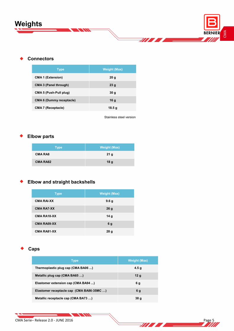
Weights
Connectors
Elbow and straight backshells
Elbow parts
Type Weight (Max)
CMA 1 (Extension) 20 g
CMA 3 (Panel through) 23 g
CMA 5 (Push-Pull plug) 30 g
CMA 6 (Dummy receptacle) 16 g
CMA 7 (Receptacle) 18.5 g
Type Weight (Max)
CMA RA8 21 g
CMA RA82 18 g
Type Weight (Max)
CMA RAI-XX 9.6 g
CMA RA7-XX 26 g
CMA RA18-XX 14 g
CMA RA09-XX 6 g
CMA RA81-XX 28 g
Stainless steel version
Caps
Type Weight (Max)
Thermoplastic plug cap (CMA BA06 ...) 4.5 g
Metallic plug cap (CMA BA65 …) 12 g
Elastomer extension cap (CMA BA94 ...) 6 g
Elastomer receptacle cap (CMA BA86-35MC …) 6 g
Metallic receptacle cap (CMA BA73 …) 38 g
Page 6 CMA Serie– Release 2.0—JUNE 2016
CM
A
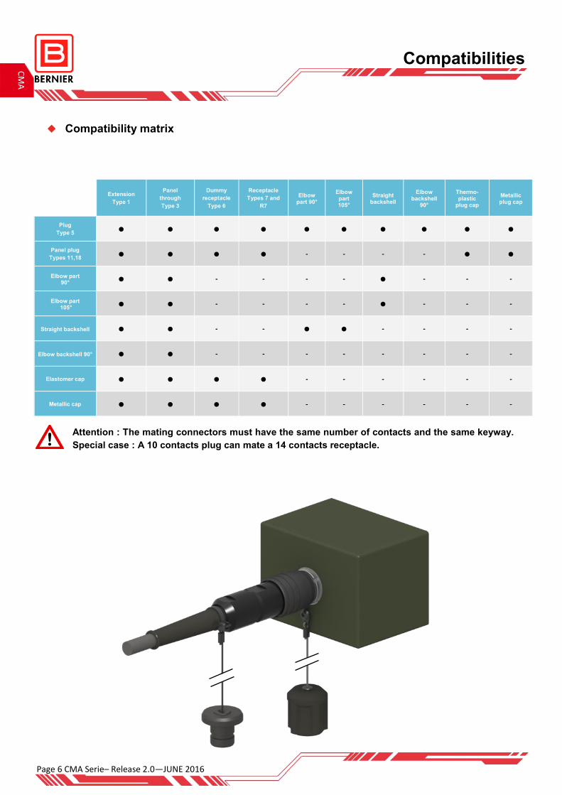
Compatibility matrix
Compatibilities
Extension
Type 1
Panel
through
Type 3
Dummy
receptacle
Type 6
Receptacle
Types 7 and
R7
Elbow part 90°
Elbow part 105°
Straight backshell
Elbow backshell
90°
Thermo-plastic
plug cap
Metallic plug cap
Plug
Type 5 • • • • • • • • • •
Panel plug
Types 11,18 • • • • - - - - • •
Elbow part 90° • • - - - - • - - -
Elbow part 105° • • - - - - • - - -
Straight backshell • • - - • • - - - -
Elbow backshell 90° • • - - - - - - - -
Elastomer cap • • • • - - - - - -
Metallic cap • • • • - - - - - -
Attention : The mating connectors must have the same number of contacts and the same keyway.
Special case : A 10 contacts plug can mate a 14 contacts receptacle.
CMA Serie– Release 2.0 - JUNE 2016 Page 7
CM
A
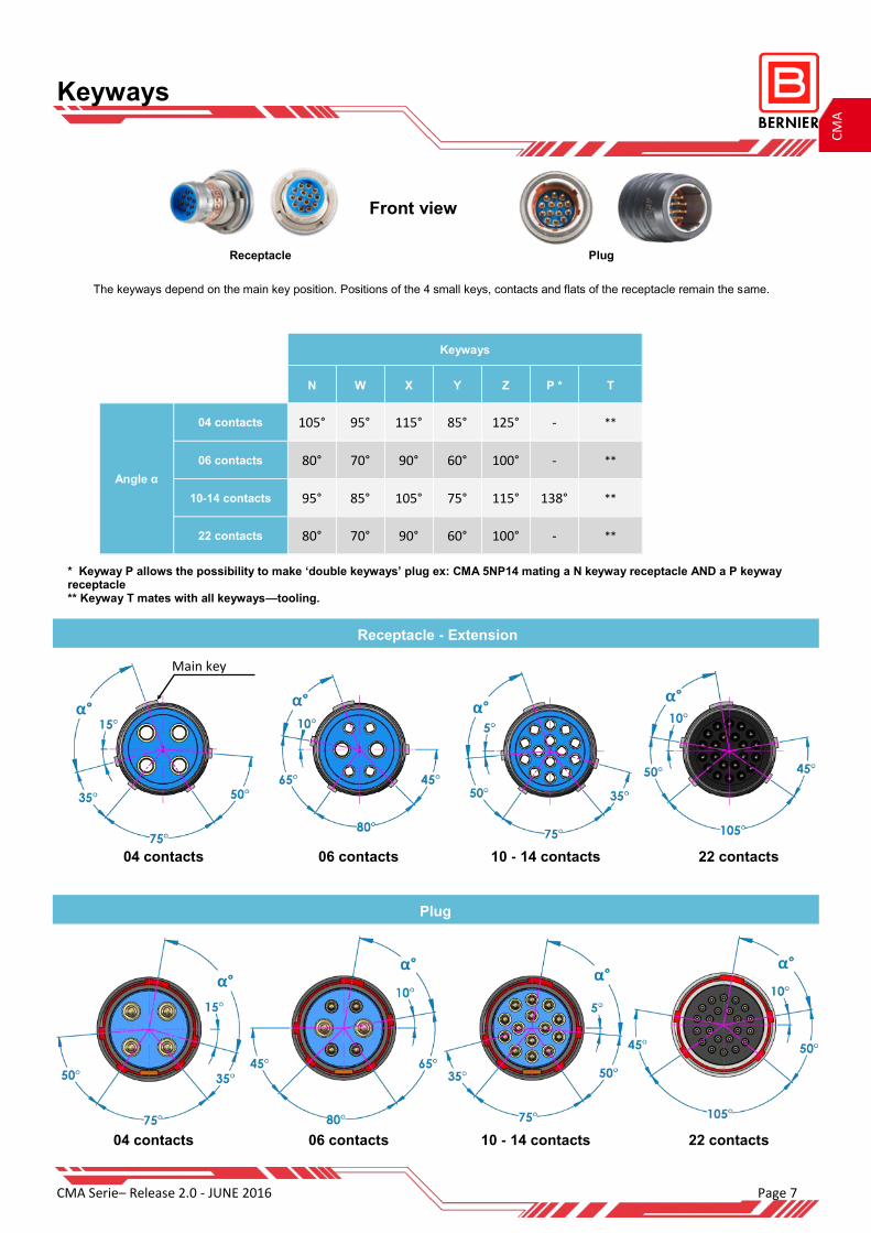
Keyways
Front view
Keyways
N W X Y Z P * T
105° 95° 115° 85° 125° - **
Angle α
04 contacts
80° 70° 90° 60° 100° - ** 06 contacts
95° 85° 105° 75° 115° 138° ** 10-14 contacts
80° 70° 90° 60° 100° - ** 22 contacts
The keyways depend on the main key position. Positions of the 4 small keys, contacts and flats of the receptacle remain the same.
* Keyway P allows the possibility to make ‘double keyways’ plug ex: CMA 5NP14 mating a N keyway receptacle AND a P keyway receptacle ** Keyway T mates with all keyways—tooling.
Receptacle - Extension
Plug
04 contacts 06 contacts 10 - 14 contacts 22 contacts
Receptacle Plug
04 contacts 06 contacts 10 - 14 contacts 22 contacts
Main key

Page 8 CMA Serie– Release 2.0—JUNE 2016
CM
A
Synoptic
A backshell (necessary for cable assembling) must be ordered at the same time than a connector and the reverse
Extension
Type 1
Elastomer extension cap
Push-Pull Plug
Type 5
Straight
backshell
Elbow
backshell 90°
Straight
backshell with
sleeve
Elbow part 90°
Elbow part 105°
Quick-releasable
plug
Type 5
Metallic extension cap
Metallic plug cap
Items mounted on cable
Thermo-plastic plug cap
Option
Option
Assembly on cable
Straight backshell with sleeve version
CMA Serie– Release 2.0 - JUNE 2016 Page 9
CM
A
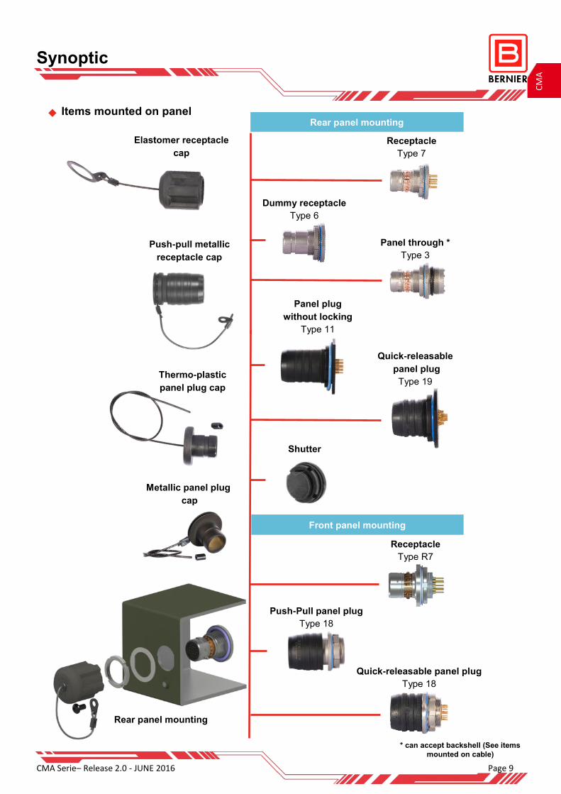
Synoptic
Elastomer receptacle
cap
Thermo-plastic
panel plug cap
Metallic panel plug
cap
Items mounted on panel
* can accept backshell (See items
mounted on cable)
Rear panel mounting
Shutter
Rear panel mounting
Front panel mounting
Quick-releasable panel plug
Type 18
Panel plug
without locking
Type 11
Quick-releasable
panel plug
Type 19
Receptacle
Type 7
Dummy receptacle
Type 6
Push-pull metallic
receptacle cap
Receptacle
Type R7
Push-Pull panel plug
Type 18
Panel through *
Type 3

Page 10 CMA Serie– Release 2.0—JUNE 2016
CM
A
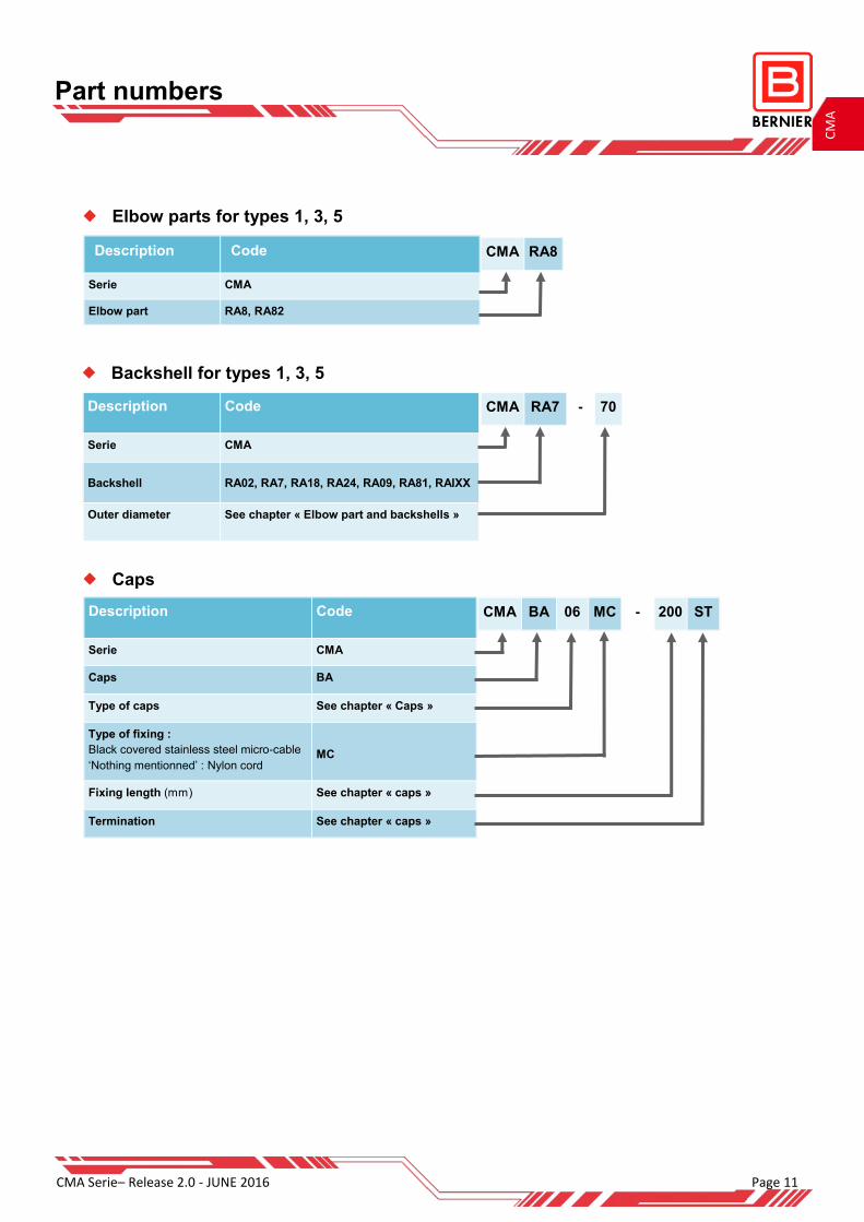
Part numbers
Connectors
CMA B 7 N 14 Y1 PM JC SM Description Code
Serie CMA
Aspect :
‘Nothing mentionned’ : Sandblasted version
Black version (by default for type 5)
Locking (Type 5, 18) :
‘Nothing mentionned’ : Push-pull version
Quick-releasable version with spring clip
Quick-releasable version without locking
B
L
SC
Connector Type :
Extension
Panel Through
Plug
Dummy receptacle
Receptacle
Panel Plug
1
3
5
6
2, 7, R7
11, 17, 18, 19
Keyways N, W, X, Y, Z, P, T
Number of contacts 04, 06, 10, 14, 22
Contacts :
‘Nothing mentionned’ : Solder cup
For PCB Type 7, R7
For PCB Type 5, 18
Y1, Y1.2, Y1.3, Y2, Y3,
Y4, Y4.1, Y4.2 Y8, Y8.1
Y, YA
Ground pin
1 ground pin
4 ground pins
PM
PM4S
Panel Oring, conductive Oring option
‘Nothing mentionned’ : Fluorosilicon Oring
Fluorosilicon charged with Ni/Graph Oring
Fluorosilicon charged with Silver/Alu Oring
JC
JC1
Material :
‘Nothing mentionned’ : Stainless steel
Marine stainless steel 250 Hours Salt fog
Navy Bronze 500 Hours Salt fog
SM
BM
CMA Serie– Release 2.0 - JUNE 2016 Page 11
CM
A
Part numbers
Caps
CMA BA 06 MC - 200 ST Description Code
Serie CMA
Caps BA
Type of caps See chapter « Caps »
Type of fixing :
Black covered stainless steel micro-cable
‘Nothing mentionned’ : Nylon cord MC
Fixing length (mm) See chapter « caps »
Termination See chapter « caps »
Backshell for types 1, 3, 5
CMA RA7 - 70 Description Code
Serie CMA
Backshell RA02, RA7, RA18, RA24, RA09, RA81, RAIXX
Outer diameter See chapter « Elbow part and backshells »
Elbow parts for types 1, 3, 5
CMA RA8 Description Code
Serie CMA
Elbow part RA8, RA82

Page 12 CMA Serie– Release 2.0—JUNE 2016
CM
A
Type 7 with solder cup contacts
Type R7 rear panel mounting (can’t be dismounted by the outside of the equipment)
Version R7 with solder cup contacts possible
Number of contacts ΦA L max
04 AWG 18 7.1
06
2 contacts
4 contacts
AWG 18
AWG 22
7.1
7.1
10 AWG 22 7.1
14 AWG 22 9.1
22 AWG 26 7.1
Ex: CMA 7N06PM
Ex: CMA R7N14Y1PM
Type 7 with contacts for PCB
Contact type L max C max
Y1 3.5 4
Y1.2 3.5 2.6
Y1.3 3.5 1.5
Y2 9.5 4
Y3 12.5 4
Y4 3.2 2
Y4.1 3.2 1.3
Y4.2 3.2 1.7
Y8 5.5 4
Y8.1 5.5 2.6
Ex: CMA 7N10Y1PM
Receptacles
Contact type L max C max
Y1 8.2 4
Y1.2 8.2 2.6
Y1.3 8.2 1.5
Y2 14.2 4
Y3 17.2 4
Y4 7.9 2
Y4.1 7.9 1.3
Y4.2 7.9 1.7
Y8 10.2 4
Y8.1 10.2 2.6
CMA Serie– Release 2.0 - JUNE 2016 Page 13
CM
A
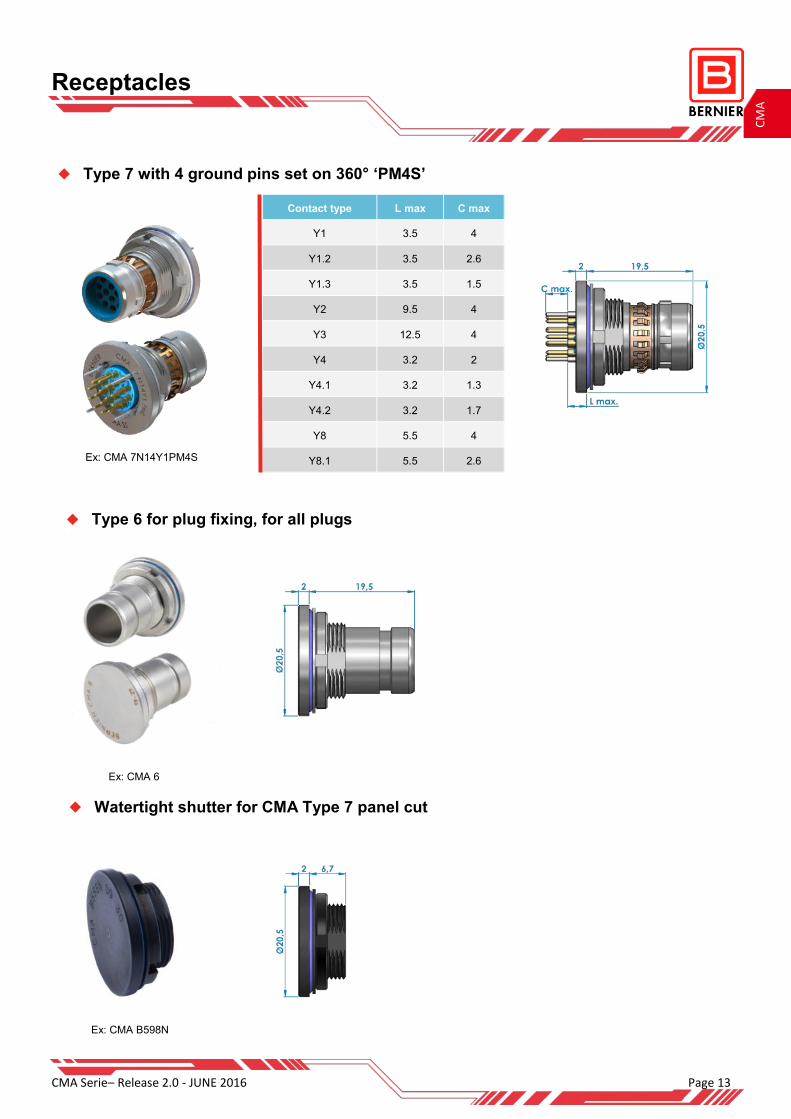
Receptacles
Type 6 for plug fixing, for all plugs
Ex: CMA 6
Watertight shutter for CMA Type 7 panel cut
Ex: CMA B598N
Type 7 with 4 ground pins set on 360° ‘PM4S’
Contact type L max C max
Y1 3.5 4
Y1.2 3.5 2.6
Y1.3 3.5 1.5
Y2 9.5 4
Y3 12.5 4
Y4 3.2 2
Y4.1 3.2 1.3
Y4.2 3.2 1.7
Y8 5.5 4
Y8.1 5.5 2.6 Ex: CMA 7N14Y1PM4S
Page 14 CMA Serie– Release 2.0—JUNE 2016
CM
A
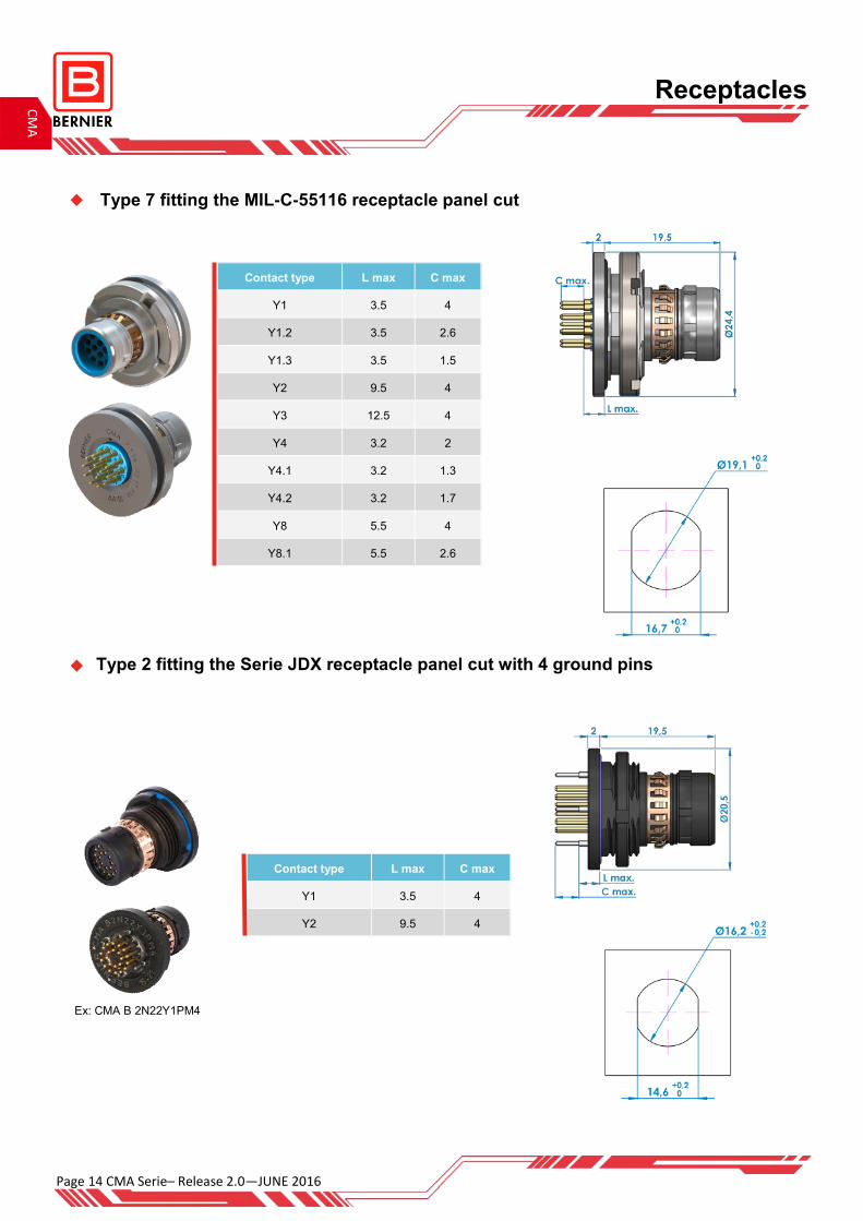
Receptacles
Type 7 fitting the MIL-C-55116 receptacle panel cut
Contact type L max C max
Y1 3.5 4
Y1.2 3.5 2.6
Y1.3 3.5 1.5
Y2 9.5 4
Y3 12.5 4
Y4 3.2 2
Y4.1 3.2 1.3
Y4.2 3.2 1.7
Y8 5.5 4
Y8.1 5.5 2.6
Type 2 fitting the Serie JDX receptacle panel cut with 4 ground pins
Contact type L max C max
Y1 3.5 4
Y2 9.5 4
Ex: CMA B 2N22Y1PM4
CMA Serie– Release 2.0 - JUNE 2016 Page 15
CM
A
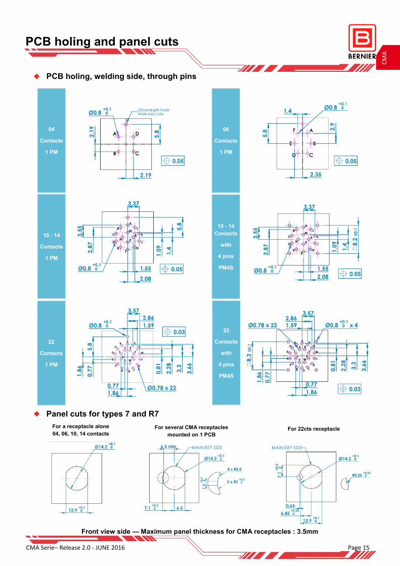
PCB holing and panel cuts
PCB holing, welding side, through pins
Panel cuts for types 7 and R7
04
Contacts
1 PM
Front view side — Maximum panel thickness for CMA receptacles : 3.5mm
For a receptacle alone
04, 06, 10, 14 contacts
For several CMA receptacles
mounted on 1 PCB For 22cts receptacle
22
Contacts
1 PM
10 - 14
Contacts
1 PM
06
Contacts
1 PM
22
Contacts
with
4 pins
PM4S
10 - 14
Contacts
with
4 pins
PM4S
Page 16 CMA Serie– Release 2.0—JUNE 2016
CM
A
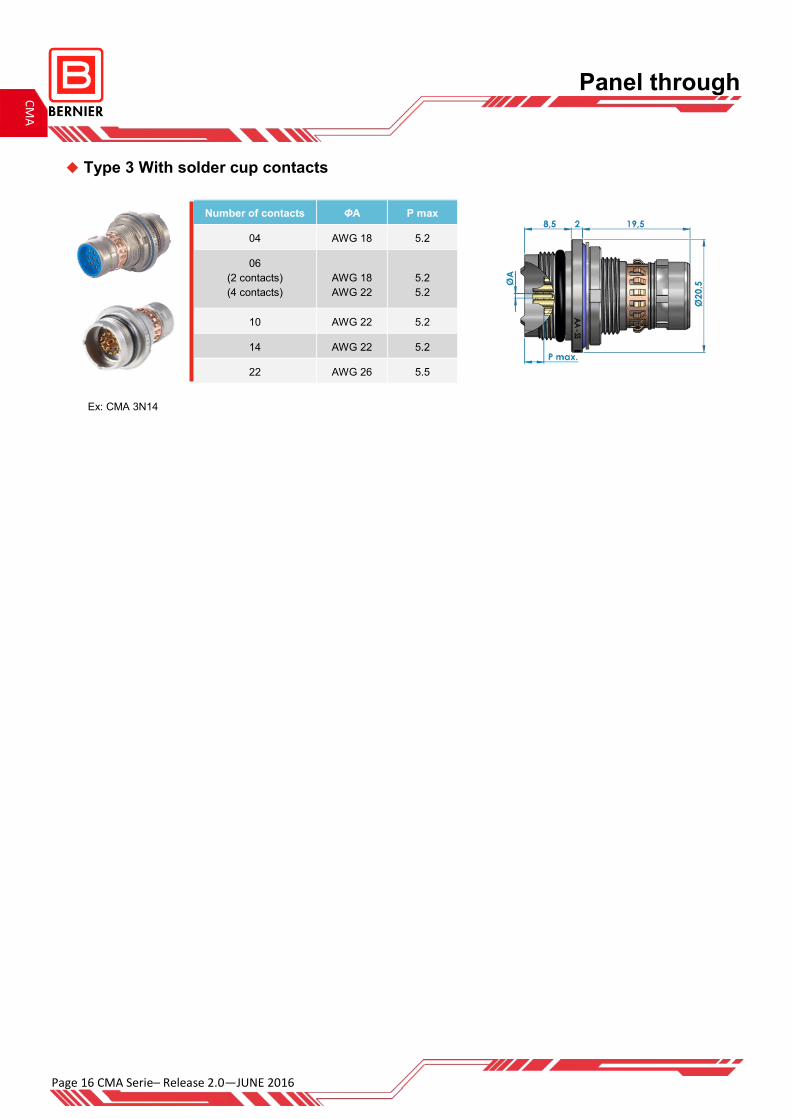
Panel through
Type 3 With solder cup contacts
Number of contacts P max ΦA
04 5.2 AWG 18
06
(2 contacts)
(4 contacts)
5.2
5.2
AWG 18
AWG 22
10 5.2 AWG 22
14 5.2 AWG 22
22 5.5 AWG 26
Ex: CMA 3N14

CMA Serie– Release 2.0 - JUNE 2016 Page 17
CM
A
Type 11 Quick-releasable with solder cup contacts
Type 11 No locking system with contacts for PCB
Number of contacts ΦA L max
04 AWG 18 4.9
06
2 contacts
4 contacts
AWG 18
AWG 22
4.9
4.9
10 AWG 22 4.9
14 AWG 22 6.9
22 AWG 26 4
Ex: CMA B L 11N04
Ex: CMA L 17Y14YAPM
Panel plugs
Version 11 Quick-releasable panel plug with contacts for PCB possible
Contact type
Y5
Contact type L max C max
Y 1.7 1.2
YA 3.7 3.2
Type 17 Quick-releasable with contacts for PCB
Ex: CMA 11N14Y5
Version 17 Quick-releasable panel plug with solder cup contacts possible

Page 18 CMA Serie– Release 2.0—JUNE 2016
CM
A
Panel plugs
Type 18 Push-Pull with solder cup contacts
Number of contacts P max ΦA
04 4.7 AWG 18
06
(2 contacts)
(4 contacts)
4.7
4.7
AWG 18
AWG 22
10 4.7 AWG 22
14 4.7 AWG 22
22 7.1 AWG 26
Version 18 Push-Pull panel plug with contacts for PCB possible
Ex: CMA 18N14
Type 18 Quick-releasable with contacts for PCB
Ex: CMA L 18N14YA
Contact type L max C max
Y 6.2 1.2
YA 8.2 3.2
Ex: CMA B L 19N14
Type 19 Quick-releasable with solder cup contacts
Version 18 Quick releasable panel plug with solder cup contacts possible
Version 19 Quick-releasable panel plug with contacts for PCB possible
Number of contacts ΦA L max
04 AWG 18 5
06
(2 contacts)
(4 contacts)
AWG 18
AWG 22
5
5
10 AWG 22 5
14 AWG 22 7
22 AWG 26 3.9
CMA Serie– Release 2.0 - JUNE 2016 Page 19
CM
A
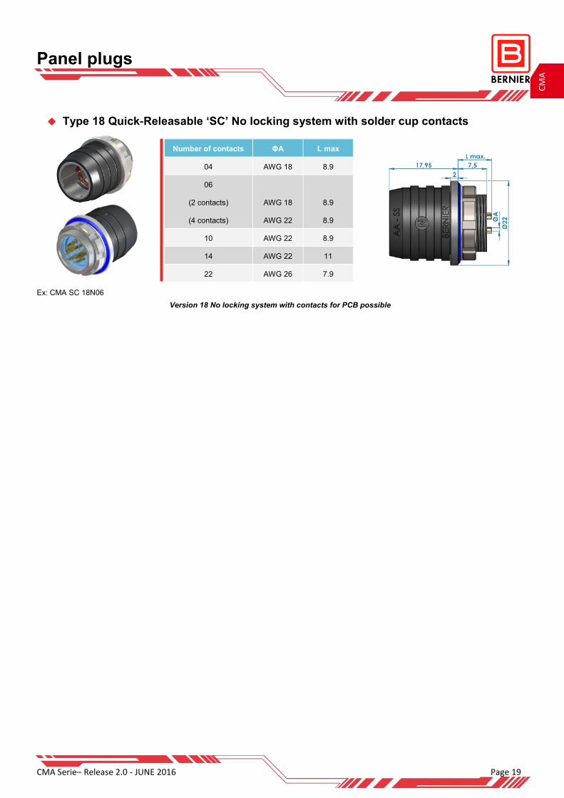
Type 18 Quick-Releasable ‘SC’ No locking system with solder cup contacts
Number of contacts ΦA L max
04 AWG 18 8.9
06
(2 contacts)
(4 contacts)
AWG 18
AWG 22
8.9
8.9
10 AWG 22 8.9
14 AWG 22 11
22 AWG 26 7.9
Version 18 No locking system with contacts for PCB possible
Ex: CMA SC 18N06
Panel plugs
Page 20 CMA Serie– Release 2.0—JUNE 2016
CM
A
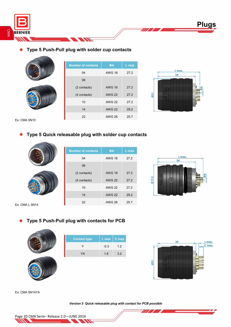
Plugs
Type 5 Push-Pull plug with solder cup contacts
Type 5 Quick releasable plug with solder cup contacts
Type 5 Push-Pull plug with contacts for PCB
Number of contacts ΦA L max
04 AWG 18 27.2
06
(2 contacts)
(4 contacts)
AWG 18
AWG 22
27.2
27.2
10 AWG 22 27.2
14 AWG 22 29.2
22 AWG 26 25.7
Number of contacts ΦA L max
04 AWG 18 27.2
06
(2 contacts)
(4 contacts)
AWG 18
AWG 22
27.2
27.2
10 AWG 22 27.2
14 AWG 22 29.2
22 AWG 26 25.7
Contact type L max C max
Y -0.3 1.2
YA 1.8 3.2
Ex: CMA 5N10
Ex: CMA L 5N14
Ex: CMA 5N14YA
Version 5 Quick releasable plug with contact for PCB possible

CMA Serie– Release 2.0 - JUNE 2016 Page 21
CM
A
Extensions
Type 1 Extension with solder cup contacts
Type 1 extension with solder cup contacts and integrated backshell
Number of contacts ΦA L max
04 AWG 18 11.4
06
(2 contacts)
(4 contacts)
AWG 18
AWG 22
11.4
11.4
10 AWG 22 11.4
14 AWG 22 13.4
22 AWG 26 11.4
Number of contacts ΦA L max
04 AWG 18 10.9
06
(2 contacts)
(4 contacts)
AWG 18
AWG 22
10.9
10.9
10 AWG 22 10.9
14 AWG 22 12.9
22 AWG 26 10.9
Ex: CMA 1N22
Ex: CMA 1N22SP
Page 22 CMA Serie– Release 2.0—JUNE 2016
CM
A
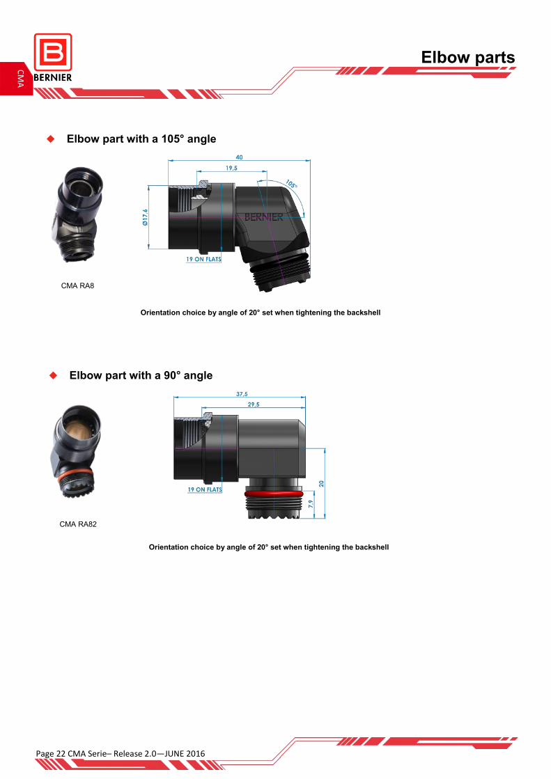
Elbow part with a 105° angle
Orientation choice by angle of 20° set when tightening the backshell
Elbow parts
CMA RA8
CMA RA82
Elbow part with a 90° angle
Orientation choice by angle of 20° set when tightening the backshell

CMA Serie– Release 2.0 - JUNE 2016 Page 23
CM
A
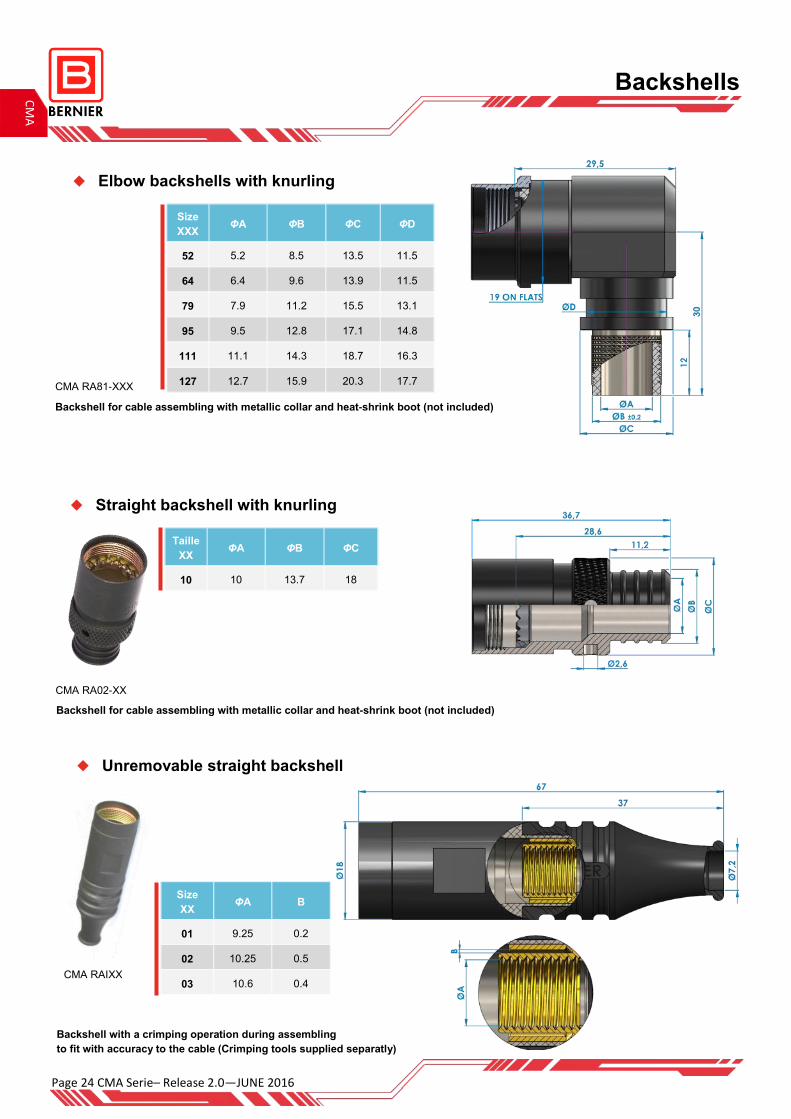
Backshells
Straight backshell with knurling
Size
XXX ΦA ΦB ΦC ΦD
52 5.2 8.5 13.5 11.5
64 6.4 9.6 13.9 11.5
79 7.9 11.2 15.5 13.1
95 9.5 12.8 17.1 14.8
111 11.1 14.3 18.7 16.3
127 12.7 15.9 20.3 17.7 CMA RA18-XXX
Backshell for cable assembling with metallic collar and heat-shrink boot (not included)
Size XX
ΦA
45 4.5
55 5.5
60 6
70 7
80 8
CMA RA7-XX
Cable clamp and sleeve included
Straight backshell with sleeve
CMA RA24-XX
Straight backshell with knurling
Size XX
ΦA ΦB ΦC ΦD
52 5.2 8.3 15.5 13.1
64 6.4 9.4 15.5 13.1
79 7.9 11 15.5 13.1
83 8.3 11 15.5 13.1
Diameters C and D don’t change.
Backshell for overmolding or cable assembling with metallic collar and heat shrink boot (not included)
Page 24 CMA Serie– Release 2.0—JUNE 2016
CM
A
Backshells
Unremovable straight backshell
Straight backshell with knurling
Size
XX ΦA B
01 9.25 0.2
02 10.25 0.5
03 10.6 0.4 CMA RAIXX
Backshell with a crimping operation during assembling
to fit with accuracy to the cable (Crimping tools supplied separatly)
CMA RA02-XX
Taille
XX ΦA ΦB ΦC
10 10 13.7 18
Size
XXX ΦA ΦB ΦC ΦD
52 5.2 8.5 13.5 11.5
64 6.4 9.6 13.9 11.5
79 7.9 11.2 15.5 13.1
95 9.5 12.8 17.1 14.8
111 11.1 14.3 18.7 16.3
127 12.7 15.9 20.3 17.7 CMA RA81-XXX
Elbow backshells with knurling
Backshell for cable assembling with metallic collar and heat-shrink boot (not included)
Backshell for cable assembling with metallic collar and heat-shrink boot (not included)
CMA Serie– Release 2.0 - JUNE 2016 Page 25
CM
A
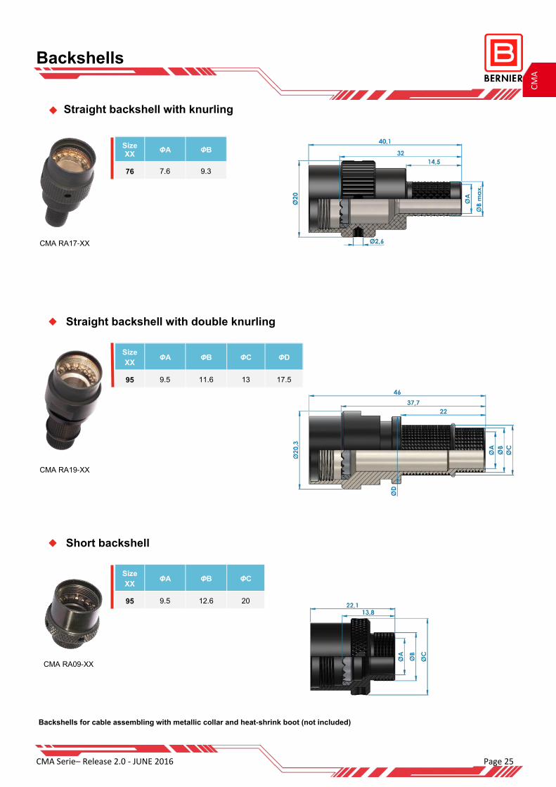
Backshells
Size
XX ΦA ΦB ΦC
95 9.5 12.6 20
CMA RA09-XX
Straight backshell with double knurling
Straight backshell with knurling
Short backshell
CMA RA19-XX
CMA RA17-XX
Size
XX ΦA ΦB ΦC ΦD
95 9.5 11.6 13 17.5
Size XX
ΦA ΦB
76 7.6 9.3
Backshells for cable assembling with metallic collar and heat-shrink boot (not included)
Page 26 CMA Serie– Release 2.0—JUNE 2016
CM
A
Caps
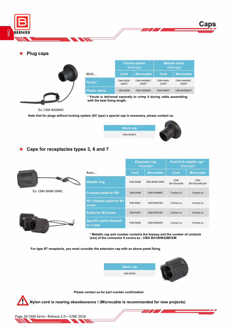
Plug caps
Caps for receptacles types 3, 6 and 7
Ex: CMA BA06MC
Thermo-plastic
Watertight
Metallic black
Watertight
With... Cord Microcable Cord Microcable
Ferule* CMA BA06-
200ST
CMA BA06MC-
200ST
CMA BA65-
200ST
CMA BA65MC-
200ST
Plastic clamp CMA BA06 CMA BA06MC CMA BA65T CMA BA65MCT
Elastomer cap
Watertight
Push-Pull metallic cap *
Watertight
Avec... Cord Microcable Cord Microcable
Metallic ring CMA BA86 CMA BA86-35MC CMA
BA100xxxEM
CMA
BA100xxxMCEM
Crimped eyelet for M3 CMA BA98 CMA BA98MC Contact us Contact us
90° crimped eyelet for M3
screw CMA BA81 CMA BA81MC Contact us Contact us
Eyelet for M3 screw CMA BA91 CMA BA91MC Contact us Contact us
Specific eyelet attached
to 3 caps CMA BA84 CMA BA84MC Contact us Contact us
Stock cap
CMA BASFIL
Stock cap
CMA BA20
* Metallic cap part number contains the keyway and the number of contacts (xxx) of the connector it covers ex : CMA BA100W22MCEM
* Ferule is delivered separatly to crimp it during cable assembling
with the best fixing length.
Nylon cord is nearing obsolescence ! (Microcable is recommanded for new projects)
Ex: CMA BA86-35MC
For type R7 receptacle, you must consider the extension cap with an above panel fixing.
Please contact us for part number confirmation
Note that for plugs without locking system (SC type) a special cap is necessary, please contact us.
CMA Serie– Release 2.0 - JUNE 2016 Page 27
CM
A
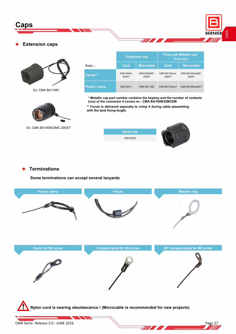
Some terminations can accept several lanyards
Terminations
Caps
Plastic clamp Metallic ring Ferule
Eyelet for M3 screw 90° crimped eyelet for M3 screw Crimped eyelet for M3 screw
Extension caps
Ex: CMA BA11MC
Elastomer cap
Push-pull Métallic cap*
Watertight
Avec... Cord Microcable Cord Microcable
Ferule** CMA BA94-
200ST
CMA BA94MC-
200ST
CMA BA100xxx-
200ST
CMA BA100xxxMC-
200ST
Plastic clamp CMA BA11 CMA BA11MC CMA BA100xxxT CMA BA100xxxMCT
Stock cap
CMA BA20
Ex: CMA BA100N22MC-200ST
** Ferule is delivered separatly to crimp it during cable assembling
with the best fixing length.
* Metallic cap part number contains the keyway and the number of contacts (xxx) of the connector it covers ex : CMA BA100W22MCEM
Nylon cord is nearing obsolescence ! (Microcable is recommanded for new projects)

Page 28 CMA Serie– Release 2.0—JUNE 2016
CM
A
Modules
Connectors with electronic functions integrated
Wireless module
Bluetooth antenna
User authentification module
Crypto / Shunt
Special connectors
Memory key Adaptator
Several memory sizes available CMA—Industrial connector (RJ45, USB, HDMI, ...)
Plug with special shapes for rackable system
CMA 14N06
105° Elbow adaptator with point to point cabling
CMA plug - CMA extension
Panel plug with removable insulator
Used on maintenance of crypto device

CMA Serie– Release 2.0 - JUNE 2016 Page 29
CM
A
Others
Panel throughs
Similar to CMA RA7-XX backshell construction For cable shield continuity and heat-shrink boot
B456 B459
Development of products in the CMA environment
Double cap for BNC receptacle and antenna connector
B598

Page 30 CMA Serie– Release 2.0—JUNE 2016
CM
A
Accessories
Kits with Oring Washer and Nut for receptacle type 7 and R7 Part numbers
Kit Oring-Washer-Nut (standard) BEN000ME000
Kit Oring-Circular washer-Nut BEN000ME001
Kit conductive Oring-Washer-Nut (JC fluorosilicon charged Nickel-Graphite) BEN000ME002
Kit conductive Oring-Washer-Nut (JC1 fluorosilicon charged Silver-Aluminium) BEN000ME003
Accessories
PN L (mm) h (mm) l1 (mm) l2 (mm) Ep. (mm) Metallic clamp for backshells
B593 362.1 1.88 8.9 6.1 0.51 Metallic clamp width 6.10mm
B452 206.4 1.35 5 3.1 0.4 Metallic clamp width 3.17mm
BEN000ME000 BEN000ME001 BEN000ME003 BEN000ME002
CMA Serie– Release 2.0 - JUNE 2016 Page 31
CM
A
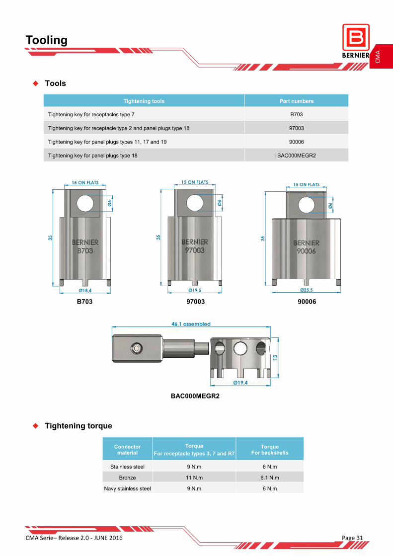
Connector material
Torque
For receptacle types 3, 7 and R7 Torque
For backshells
Stainless steel 9 N.m 6 N.m
Bronze 11 N.m 6.1 N.m
Navy stainless steel 9 N.m 6 N.m
Tightening tools Part numbers
Tightening key for receptacles type 7 B703
Tightening key for receptacle type 2 and panel plugs type 18 97003
Tightening key for panel plugs types 11, 17 and 19 90006
Tightening key for panel plugs type 18 BAC000MEGR2
Tightening torque
Tools
B703 97003 90006
BAC000MEGR2
Tooling

Page 32 CMA Serie– Release 2.0—JUNE 2016
CM
A
Tools
Mechanical counter part Part number
Antirotation plug to tighten the backshell on extension with xx contacts BOUExxMENA01
Antirotation receptacle to tighten the backshell on plug with xx contacts BOUFxxMENA01
Electrical counter part Part number
Panel plug to test all keyways receptacle and extension CMA 12TxxYA ( xx : number of contacts)
Receptacle to test all keyways plug CMA 7TxxY1 (xx : number of contacts)
CMA 12T14YA CMA 7T14Y1
Tooling
Ex: BOUF14MENA01 Ex: BOUE14MENA01
Available with solder cup contacts
CMA Serie– Release 2.0 - JUNE 2016 Page 33
CM
A
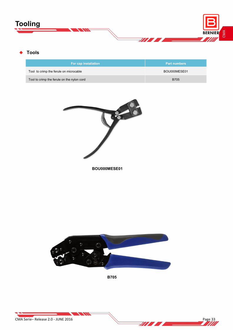
Tools
For cap installation Part numbers
Tool to crimp the ferule on microcable BOU000MESE01
Tool to crimp the ferule on the nylon cord B705
B705
Tooling
BOU000MESE01
Page 34 CMA Serie– Release 2.0—JUNE 2016
CM
A
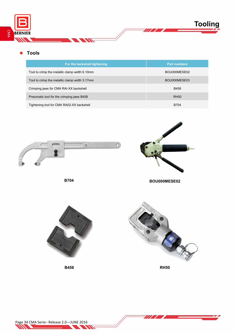
Tooling
Tools
For the backshell tightening Part numbers
Tool to crimp the metallic clamp width 6.10mm BOU000MESE02
Tool to crimp the metallic clamp width 3.17mm BOU000MESE03
Crimping jaws for CMA RAI-XX backshell B458
Pneumatic tool for the crimping jaws B458 RH50
Tightening tool for CMA RA02-XX backshell B704
BOU000MESE02
B458 RH50
B704
CMA Serie– Release 2.0 - JUNE 2016 Page 35
CM
A
04 Contacts 06 Contacts 10 Contacts 14 contacts 22 Contacts
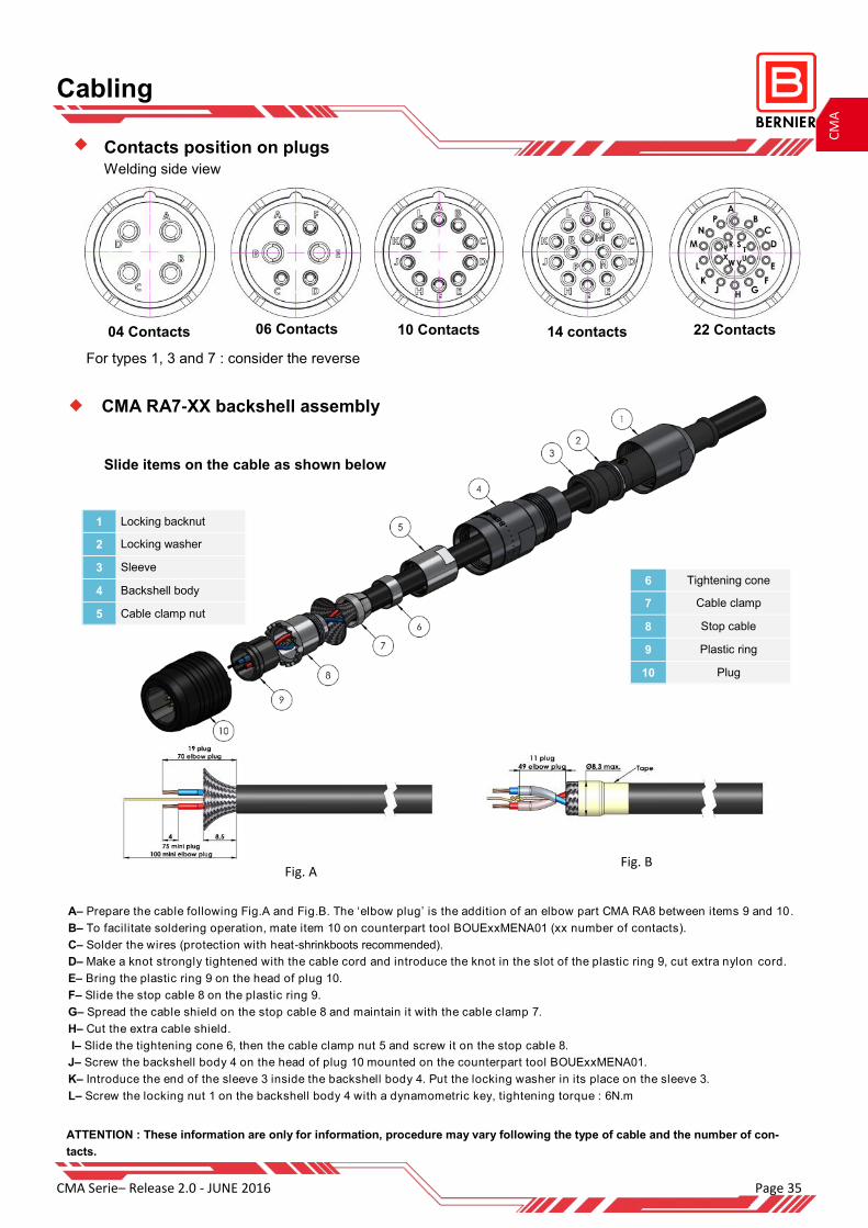
CMA RA7-XX backshell assembly
Slide items on the cable as shown below
A– Prepare the cable following Fig.A and Fig.B. The ‘elbow plug’ is the addition of an elbow part CMA RA8 between items 9 and 10.
B– To facilitate soldering operation, mate item 10 on counterpart tool BOUExxMENA01 (xx number of contacts).
C– Solder the wires (protection with heat-shrinkboots recommended).
D– Make a knot strongly tightened with the cable cord and introduce the knot in the slot of the plastic ring 9, cut extra nylon cord.
E– Bring the plastic ring 9 on the head of plug 10.
F– Slide the stop cable 8 on the plastic ring 9.
G– Spread the cable shield on the stop cable 8 and maintain it with the cable clamp 7.
H– Cut the extra cable shield.
I– Slide the tightening cone 6, then the cable clamp nut 5 and screw it on the stop cable 8.
J– Screw the backshell body 4 on the head of plug 10 mounted on the counterpart tool BOUExxMENA01.
K– Introduce the end of the sleeve 3 inside the backshell body 4. Put the locking washer in its place on the sleeve 3.
L– Screw the locking nut 1 on the backshell body 4 with a dynamometric key, tightening torque : 6N.m
Cabling
6 Tightening cone
7 Cable clamp
8 Stop cable
9 Plastic ring
10 Plug
1 Locking backnut
2 Locking washer
3 Sleeve
4 Backshell body
5 Cable clamp nut
Fig. A Fig. B
ATTENTION : These information are only for information, procedure may vary following the type of cable and the number of con-
tacts.
For types 1, 3 and 7 : consider the reverse
Contacts position on plugs
Welding side view

Page 36 CMA Serie– Release 2.0—JUNE 2016
CM
A
Cabling overview for CMA RA18-XXX and CMA RA24-XXX backshells
Cabling
Cabling overview of CMA RAIXX backshells
-Prepare cable and backshell items (metallic clamp and
heat shrink boot not included in the backshell part number)
-Solder the cable wires on the connector contacts
-Prepare cable and backshell items
-Solder the cable wires on the connector
contacts
-Tighten (with the recommanded torque) the backshell
on the connector.
-Tighten the metallic clamp to fix the cable shield on the
backshell knurled area.
-Cover with a heat shrink boot, a molded part or
proceed an overmolding operation.
-Tighten (with the recommanded torque) the
backshell on the connector.
-Bring the assembly ‘Ferrule-shield-cable ‘
in position inside the backshell pulling on
the cable.
-Proceed the crimping operation following
the datasheet and the recommended tools.
-Bring the Orings and the elastomer sleeve in
position.
1 2
1 2 3
CMA Serie– Release 2.0 - JUNE 2016 Page 37
CM
A
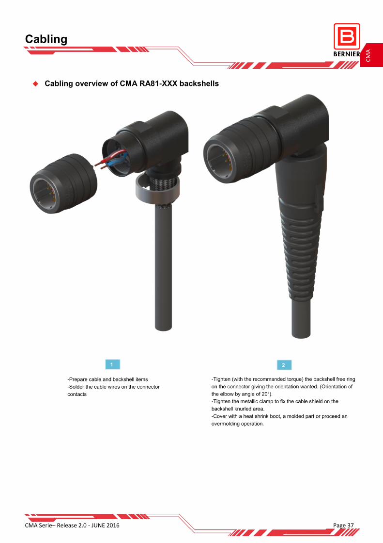
Cabling
Cabling overview of CMA RA81-XXX backshells
-Tighten (with the recommanded torque) the backshell free ring
on the connector giving the orientation wanted. (Orientation of
the elbow by angle of 20°).
-Tighten the metallic clamp to fix the cable shield on the
backshell knurled area.
-Cover with a heat shrink boot, a molded part or proceed an
overmolding operation.
1 2
-Prepare cable and backshell items
-Solder the cable wires on the connector
contacts

BERNIER Relais et Connecteurs 2 rue du Languedoc 91220 BRETIGNY SUR ORGE FRANCE
Tel : 33 (0)1 60 84 21 40 Fax : 33 (0)1 60 84 43 81 [email protected]
Ask for our other catalogs :
Find more on
www.bernier.tm.fr This catalogue and its content are BERNIER property, all rights reserved
All information contained in this catalogue can be changed without prior notice
Dimensions in mm
Catalogs
CM
A