co2 separation and capture technology: present …...industries, ltd. kansai electric power co. inc....
TRANSCRIPT
1
Y. FujiokaY. FujiokaResearch Institute of Innovative Technology for the EarthResearch Institute of Innovative Technology for the Earth
CO2 separation and capture technology: Present and future
CO2 separation and capture technology: CO2 separation and capture technology: Present and future Present and future
CCS Workshop 2007CCS Workshop 20071515thth, , FebruaryFebruary , 2007, 2007The Keihanna Plaza in KyotoThe Keihanna Plaza in Kyoto
Cross section of Organic composite Membrane

2
OutlineOutline
1. Measures against global warming
2. Introduction of CO2 capture technology for CCS
3. Development of CO2 capture technology in RITE
4. Progress of organic membrane separation

3
DNE 21 ModelDNE 21 Model
Measures against global warming
Energy Saving
Fuel Switching
1. Energy managementNuclear Power
3. Nuclear Power
Ocean Seq.
Aquifer Seq.
Gas Well Seq.
EOR
4. CO2 capture and Storage
2. Renewable Energy
Biomass
Solar cell
Wind Power
Hydro & Geoth.
5. Enlargement of CO2 sinkReforestation
4
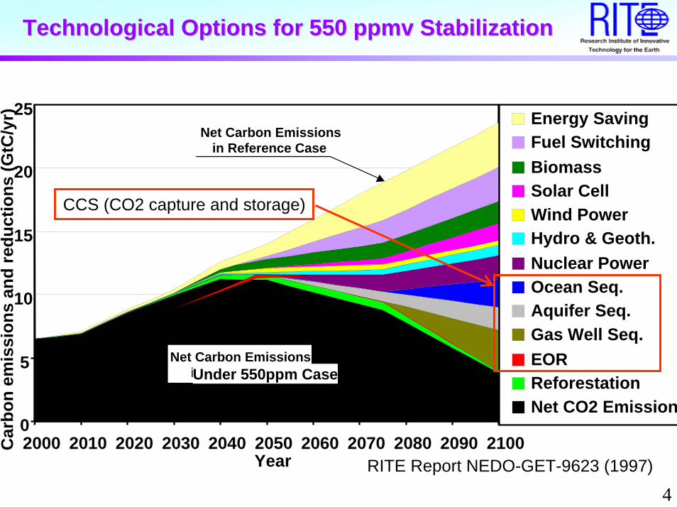
Technological Options for 550 ppmv StabilizationTechnological Options for 550 ppmv Stabilization
0
5
10
15
20
25
2000 2010 2020 2030 2040 2050 2060 2070 2080 2090 2100Year
Car
bon
emis
sion
s an
d re
duct
ions
(GtC
/yr)
Net Carbon Emissionsin 550ppmv Case
Net Carbon Emissionsin Reference Case
Energy SavingFuel SwitchingBiomassSolar CellWind PowerHydro & Geoth.Nuclear PowerOcean Seq.Aquifer Seq.Gas Well Seq.EORReforestationNet CO2 Emission
RITE Report NEDO-GET-9623 (1997)
Under 550ppm Case
CCS (CO2 capture and storage)

5
COCO22 emission without COemission without CO22 CaptureCapture
0 0.2 0.4 0.6 0.8 1
Nuclear
LNGC P.P.
LNG P.P.
Oil P.P.
Coal P.P.
ton-CO2/MWh
ConstructionFuel

6
Trend of energy cost in JapanTrend of energy cost in Japan
0
5
10
15
20
25
30
35
40
45
1990 1995 2000 2001 2002 2003 2004 2005
年
千円/トン
石炭(オーストラリア)
石油(サウジアラビア)
天然ガス(インドネシア)
針葉樹木材(アメリカ)
広葉樹木材(オーストラリア)
Ref: Trade Statistics of Ministry of Finance in JapanYear
X 1
000
JPY
/ton-
fuel
Coal (Australia)
Oil (Saudi Arabia )
NG (Indonesia)
Lumber (USA)
Lumber (Australia)
Comparison of fuel cost (% / MJ) in JapanOil : NG : Coal : Lumber = 300 : 300 : 100 : 500

7
Coal Conversion & COCoal Conversion & CO22 CaptureCapture(1) Post-Combustion Capture
H2O,N2,O2CO2,H2O,N2,O2
AirCoalDe-Dust De-
NOxDe-SOx
PC
CO2 Capture(Chemical Absorption)
CO2 Capture
Pre-Combustion De Carbonization
G/TCO,CO2,H2,H2O CO2,H2 H2H2O
(3)
De-Dust,SOx Shift Reac.
AirO2Coal GasifierASU
Air
CO2 Capture(Physical Absorption or Membrane Separation)
CO2 Capture
N2, O2
Air
Oxy-Fuel(2)
H2O
ASU
CO2,H2O,O2
AirCO2 Capture
(Cooling)
De-Dust (De-NOx) De-SOx
Heat Ex.O2Coal
PC
CO2

8
Electricity Cost with & without COElectricity Cost with & without CO22 CaptureCapture
Ref: IPCC Special Report (2005)

9
COCO22 Separation CostSeparation CostMinimum Maximum Average
[ US$/t on-CO2 avoided]
Existing PC + Chemical Absorption 45 73 59
New Designed PC + Chemical Absorption 29 51 41
NGCC + Chemical Absorption 37 74 53
IGCC + Physical Absorption 13 37 28
Oxyfuel (PC) 14 72 40
System
Ref; IPCC Special Report (2005)

10
COCO22 Separation EnergySeparation Energy
Capture MethodSeparation Energy [GJ/ton-CO2]
CO2 Source Experimental Scale
Rotational TSA 3.1 PCPCPC
PC
NG Boiler
IGCC
Oxy-fuel (Coal)
IGCC
BenchPTSA 6.5 BenchTSA 4.2 BenchChemical Absorption (MEA) 4.0 Pilot
Membrane 0.7 Beaker
Chemical Absorption (KS solution) 2.9 Pilot
Physical Absorption 1.7 Commercial
Cooling 2.5 Bench

11
SeparationSeparation EnergyEnergy
0.00
0.50
1.00
1.50
2.00
2.50
3.00
0 0.2 0.4 0.6 0.8 1
298 K
573 K
873 K
Theoretical
Initial CO2 Concentration [ - ]
Sep
erat
ion
Ene
rgy
[ G
J / t
on-C
O2
]Chemical Absorption
Physical Absorption
Membrane

12
OxyfuelOxyfuel
• Increase of energy in Oxyfuela. ASU (Air Separation Unit) ∆ 2.1 GJ/ton-CO2
b. CO2 Recirculation fun ∆ 0.3c. Cooling Water ∆ 0.1d. Total 2.5
• ASU Energy RatioPractical/Theoretical Energy = 4
It is difficult to reduce Oxyfuel energy.

13
Vision of power plant and CO2 capture
Technology Development or practical application time
PC: Pulverized coal combustion boilerNGCC: Natural gas combined cycle
IGCC: Integrated coal gasification combined cycleACC: Advanced Combined Cycle
ACC+Oxyfuel
Incr
ease
of e
cono
mic
effi
cien
cy
PC+CA
NGCC+CA
PC+Oxyfuel
IGCC+PA
IGCC+MS
IGCC+MS(or PA)+SOFC
CA: Chemical absorptionPA: Physical absorptionMS: Membrane separation

14
COCO22 Capture technology in RITECapture technology in RITE
1. Chemical AbsorptionImprovement of absorbent for CO2 for low separation energy
2. Inorganic MembraneMembrane reactor for water-gas shift reaction at high temperature
3. Organic MembraneMembrane with high CO2/N2 and CO2/H2 selectivity.

15
COCS projectCOCS project (Cost Saving CO2 Capture System )
Steel Works
Blust Furnace GasCO2 22%
(CO,H2 etc.)
CO299%
Fuel: CO2 2 %Chemical Absorption
Absorber
Regenerator
Reboiler
ObjectivesReduce CO2 Capture Cost
by half andEvaluate New Technology
Project Target: 2.5 GJ/t-CO2Future Target : 1.8 GJ/t-CO2
Low Cost of CO2absorption System
Improvement of Pre-treatment New Absorbent
Utilize of Low Grade Waste heat
in Steel Works
Pre-treatment

16
Development organization and issuersDevelopment organization and issuers
METI in Japan Issuers
Branch Laboratories
Nippon Steal co.
Mitsubishi Heavy Industries, Ltd.
Kansai Electric Power Co. inc.
New absorbent
Utilize of low grade waste heat
Duration of absorbent and process development for pilot plant
Development of absorbent and evaluation
Nippon Steal Engineering co., Ltd.
Process development and Evaluation of performances by BFG gas experimental apparatus
Committee for research promotion
Research institute of innovative technology for the earth
( RITE)

17
Development of New Absorbents Development of New Absorbents
First Step・Screening Commercial Amine・Formulate Amine CompoundSecond Step・Design and Synthesize New Amine
Amino Group: N・Electron Donor・Bond with CO2 (Formation of Carbamate or HCO3
- Anion)・Proton Acceptor( Formation of Protonated Cation)・Primary,Secondary,Tretiary Amine、Number of Amine Group
Hydroxyl Group: OH・Electron Acceptor (Activation of Amino
Group)・Hydrophilic (Increase in Solubility to water)・Formation of Hydrogen Bond(Elevation of
Boiling Point, Control of Volatility)
Steric Hindered Group:R1, R2, R3, R4・Control of Carbamate
Formation・Increase CO2 Desorption・Reduce Heat of Reaction
Example of Amine Molecule
R1
N C
R2R3 R4
C OH
R5 R6

18
2.7~2.8
GJ/t-CO2
Hea
t of C
aptu
re C
O2
4
0
1
2
3
MEA RITE-3ATargets
4.0
3.0
2.5
1.8
KS sol.
RITE-3A 開発 RITE-4
Screening of reaction rate
Screening of reaction heat
Performances of amines
Method
Results and Target Molecular design
RITE-5
ITCMEA-MDEA
CASTORTarget
3.7
2.0
RITE-4B
2.9
Measurements of heat
Estimation of kinetics
Theoretical Chemistry
Decreasing reaction energy by new absorbentDecreasing reaction energy by new absorbent
Reaction heat of CO2 release from absorbent
19
Bench scale apparatus using BFG gasBench scale apparatus using BFG gas
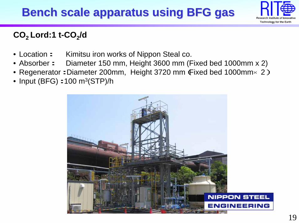
CO2 Lord:1 t-CO2/d
• Location: Kimitsu iron works of Nippon Steal co.• Absorber: Diameter 150 mm, Height 3600 mm (Fixed bed 1000mm x 2)• Regenerator: Diameter 200mm, Height 3720 mm(Fixed bed 1000mm×2)• Input (BFG): 100 m3(STP)/h

20
Inorganic Membrane ReactorInorganic Membrane Reactor
GS/T G/T
Gasifier
H2, CO,H2O
H2O
H2, CO2
Coal
H2
Inorganic Membrane > 523 K
Membrane Water-Gasshift Reactor
Catalyst
Abs
orbe
r
H2S, CO2

21
Hydrogen separation membrane with Pd Hydrogen separation membrane with Pd nano particles within nano particles within mesoporesmesopores
Cross sectional view: Mesoporous silica membrane prepared on porous alumina substrate TEM image
Schematic images

22
Organic MembraneOrganic Membrane
Water-Gasshift Reactor
GS/T G/T
Gasifier
Membrane
H2, CO,H2O
H2S, CO2
H2, CO2
Coal
CO2
H2, CO2
Membrane

23
Cost target of COCost target of CO22 Capture DevelopmentCapture Development
GasPres.
MembranePerformance(Target)
CO2Capture
GasComp.
0 2,000 4,000 6,000
ChemicalAbsorption
Flue gasAtmospheric pressure
2013 Target(New Solvent)
Membrane
IGCC CO2:40%H2, H2O4MPa
Current (KS solution)
Membrane Cost: 50,000 JPY/m2 = 420 $ / m2
JPY / t-CO2
QCO2 :1x10⁻⁹(m3 m-2 s-1 Pa-1 )αCO2/H2: 500
* Duration period Facility:15 years Membrane:5 years
Physical Absorption 1,600 ~4,400 JPY(13 ~ 37$)/t-CO2
2010 Target(New Solvent)
*
24
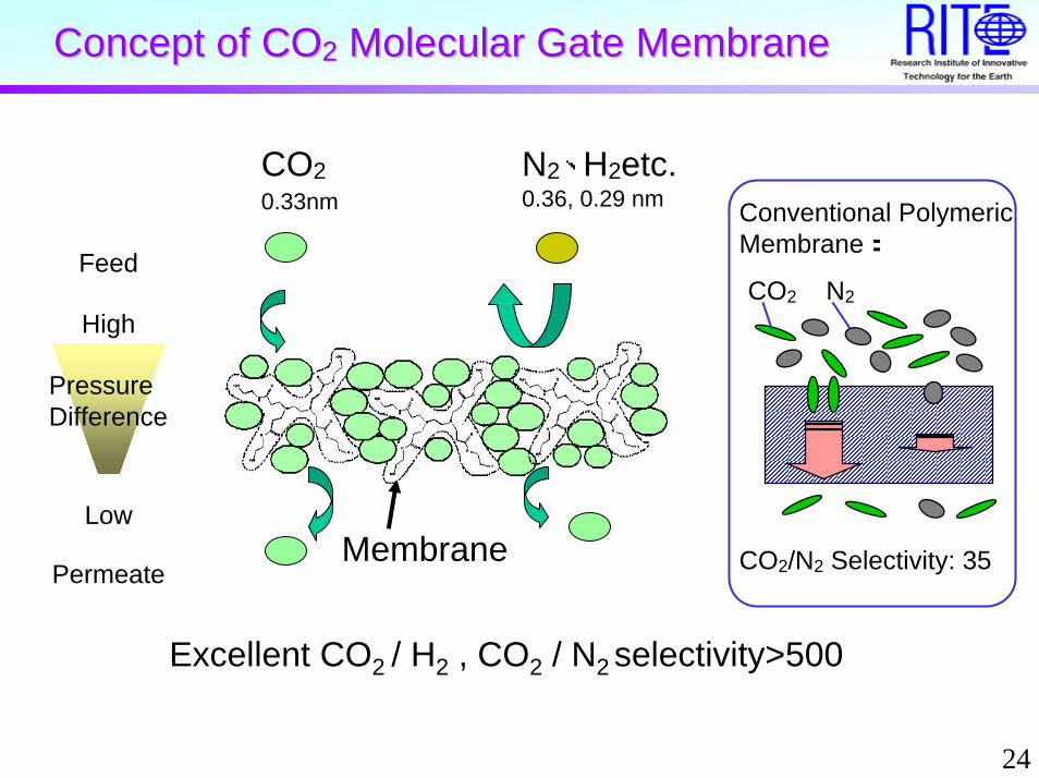
Concept of Concept of COCO22 Molecular Gate MembraneMolecular Gate Membrane
CO20.33nm
N2、H2etc.0.36, 0.29 nm Conventional Polymeric
Membrane:
CO2 N2
CO2/N2 Selectivity: 35
Feed
High
PressureDifference
Permeate
LowMembrane
Excellent CO2 / H2 , CO2 / N2 selectivity>500

25
Improvement of DendrimerImprovement of Dendrimer
N NNH
NH
NH
HN
O O
OO
NH2
NH2
H2N
H2N
Conventional PAMAM( Polyamidoamine) dendrimer
Hydroxyl PAMAM (Polyamidoamine ) dendrimer
Dendrimer 1
Dendrimer 2
CO2/N2 separation:A. S. Kovvali, H. Chen, and K. K. SirkarJ. Am. Chem. Soc. 2000, 122, 7594-7595
Optimization of chemical structure of dendrimer for CO2 molecular gate function:Computer simulation, Synthesis, Analysis
N NNH
NH
NH
HN
O O
OO
H2NHO
H2NHO
OHNH2
OHNH2
Newly Synthesized

26
Definition of Permeance & SelectivityDefinition of Permeance & Selectivity
CO2 permeance, QCO2: Ft·yCO2 / (p1·xCO2 - p2·yCO2) / AN2 permeance, QN2: Ft·yN2 / (p1·xN2 - p2·yN2) / ACO2/N2 selectivity, αCO2/N2 : QCO2/QN2
p1, xCO2, xN2
Ft, p2, yCO2, yN2
Q (m3 m-2 s-1 Pa-1): permeancex (-): molar fraction in feed, y (-): molar fraction in permeateP1 (Pa): total pressure in feed, p2 (Pa): total pressure in permeateFt (m3 s-1): total gas flux of permeateA (m2): membrane area
Feed
Permeate
Retentate
27
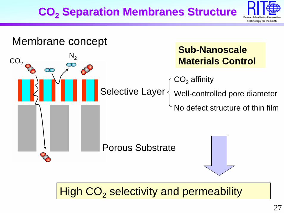
COCO22 Separation Membranes StructureSeparation Membranes Structure
CO2N2
Porous Substrate
Selective LayerCO2 affinity
Well-controlled pore diameter
Sub-Nanoscale Materials Control
No defect structure of thin film
Membrane concept
High CO2 selectivity and permeability
28
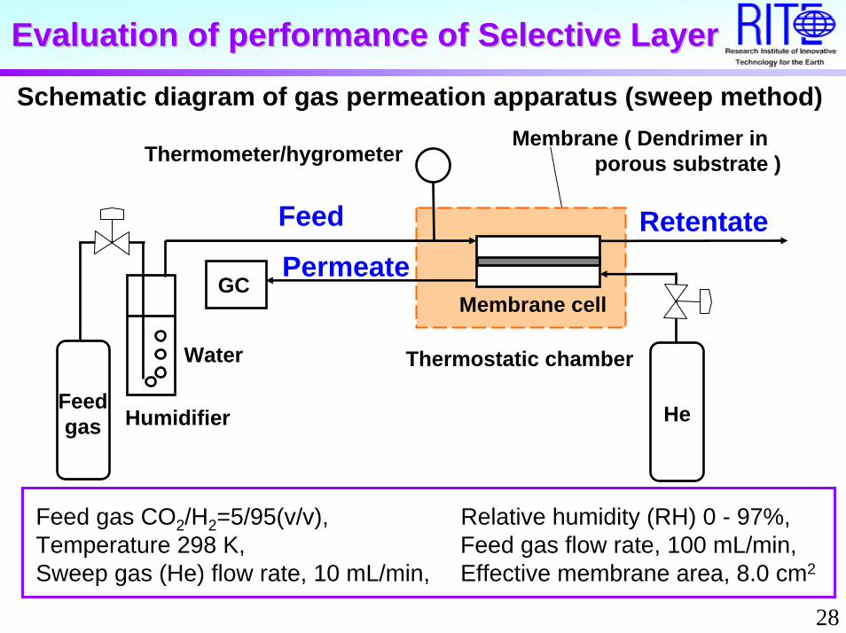
Evaluation of performance of Selective LayerEvaluation of performance of Selective Layer
Schematic diagram of gas permeation apparatus (sweep method)
Feed gas CO2/H2=5/95(v/v), Relative humidity (RH) 0 - 97%,Temperature 298 K, Feed gas flow rate, 100 mL/min, Sweep gas (He) flow rate, 10 mL/min, Effective membrane area, 8.0 cm2
Membrane ( Dendrimer in porous substrate )Thermometer/hygrometer
Membrane cellGC
Feed gas
Thermostatic chamber
Humidifier
Water
He
RetentatePermeate
Feed
29
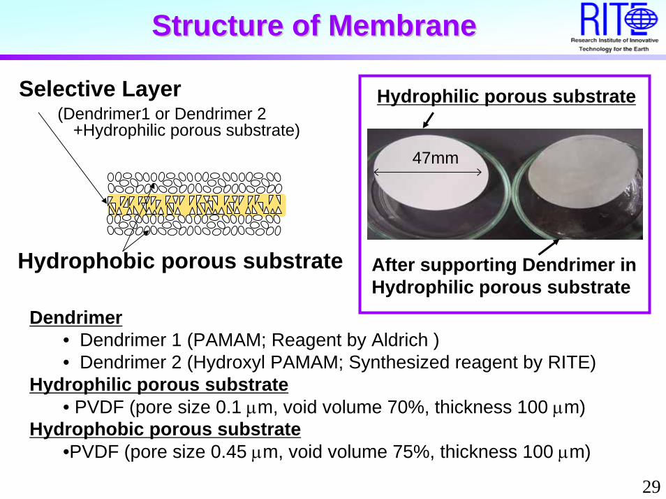
Structure of MembraneStructure of Membrane
Hydrophobic porous substrate
Hydrophilic porous substrate
47mm
After supporting Dendrimer in Hydrophilic porous substrate
Selective Layer(Dendrimer1 or Dendrimer 2
+Hydrophilic porous substrate)
Dendrimer• Dendrimer 1 (PAMAM; Reagent by Aldrich )• Dendrimer 2 (Hydroxyl PAMAM; Synthesized reagent by RITE)
Hydrophilic porous substrate• PVDF (pore size 0.1 µm, void volume 70%, thickness 100 µm)
Hydrophobic porous substrate•PVDF (pore size 0.45 µm, void volume 75%, thickness 100 µm)

30
COCO22/H/H22 Separation by DendrimerSeparation by Dendrimer
PH2
PCO2
10-14
10-13
10-12
10-11
10-10
10 -9
0 20 40 60 80 100
Per
mea
nce
[Nm3
m-2
s-1P
a-1]
Relative humidity in Feed Gas [%]
ConventionalPAMAM
HydroxylPAMAM
Conventional PAMAM CO2:●H2▲, Hydroxyl PAMAM CO2:●H2▲Feed:(CO2/H2=5/95) at 298K (25 °C),
∆pCO2=0.005MPa ∆pH2=0.095MPa
31
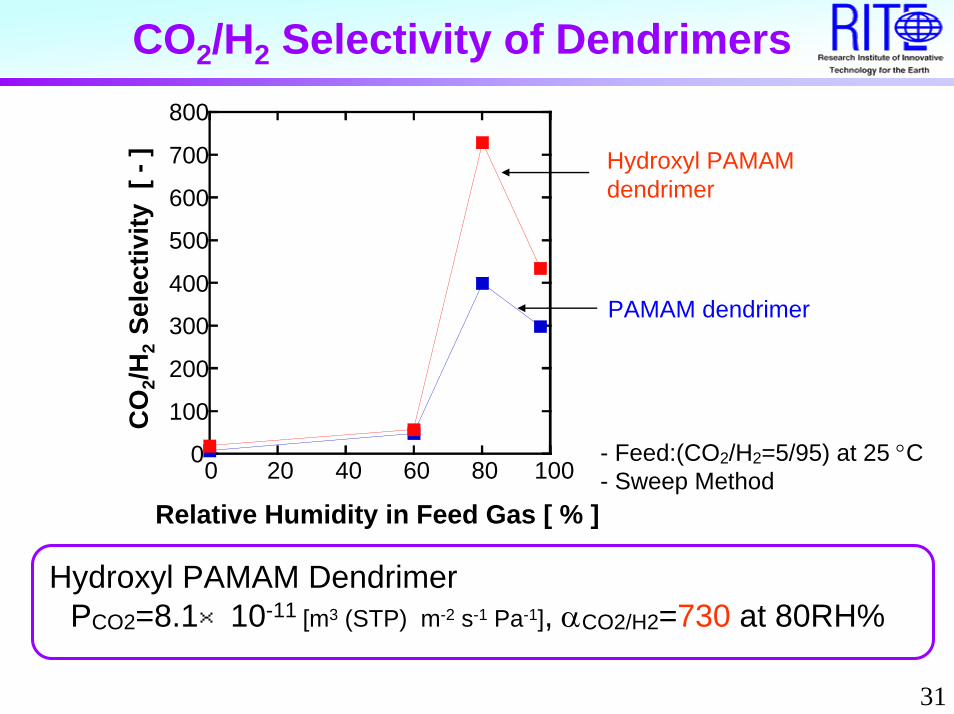
CO2/H2 Selectivity of Dendrimers
Relative Humidity in Feed Gas [ % ]
CO
2/H2
Sele
ctiv
ity [
-] Hydroxyl PAMAM
dendrimer
PAMAM dendrimer
- Feed:(CO2/H2=5/95) at 25 °C- Sweep Method
0
100
200
300
400
500
600
700
800
0 20 40 60 80 100
Hydroxyl PAMAM DendrimerPCO2=8.1×10⁻¹¹ [m3 (STP) m-2 s-1 Pa-1], αCO2/H2=730 at 80RH%

32
CO2 decreases H2 permeability
H2 PermeabilityPure gas > Mixed-gas
(CO2: 5 %)
CO2 apparentlyobstructs
H2 permeation inDendrimerMixed-gas (CO2/H2)
Pure H2
10-14
10-13
10-12
10-11
0 20 40 60 80 100
H2
Per
mea
nce
[Nm
3m
-2s-1
Pa-1
]
Mixed-gas
Pure gas
Relative Humidity in Feed Gas [ % ]
Mixed-gas Pure gas5%CO2
Dendrimer 2 ▲ ■

33
200mm200mm Membrane ModuleMembrane Module
1 mmSupport Substrate, PSF Hollow fiber
Selective Layer ,Chitosan + PAMAM Dendrimer
200 mm , φ3/8 inch

34
In-situ Module Modification Method
Hollow Fiber
Coating Solution
GlueSolution
Pump
Reduced Pressure
Membrane Module
Hollow Fiber
SupportingSubstrate
Chitosan
ReducedPressure

35
SEM Images of Selective Layer SEM Images of Selective Layer
600 nm
600 nm
600 nm
600 nm
600 nm
600 nm
200nm 300nm
100nm
(1a) (2a) (3a)
(1b) (2b) (3b)
2c) (3c)(1c) (
36
Concluding Remarks
• The combination of measures against global warming will have good effect.
• CCS is one of great measures against global warming, which is acted in advanced countries.
• Among CO2 separation system, RITE have been developing the chemical absorbent and membrane material.
• The target of RITE absorbent is decreasing the cost by half.
• If a membrane separation method will be applicable to IGCC, CO2 separation will become really economical.