coal preparation and comminution
TRANSCRIPT
Pro#. Enerqy Combust, Sci. 1984, Vol 10, pp. 273 293. 0360 1285,8450-00+ 5(I Printed in Great Britain. Pergamon Press L i d
C O A L P R E P A R A T I O N A N D C O M M I N U T I O N
L. G. AUSTIN and P. T. LUCKIE Mineral Processin 9 Section, Department of Mineral Engineering, 108 Steidle Buildiml,
The Pennsylvania State University, University Park, PA 16802, U.S.A.
I. INTRODUCTION
Coal preparation (cleaning) is an essential and economic step in the use of coals for power generation, liquefaction and gasification. The problems of air pollution are ameliorated by cleaning; the problems of poor plant availability due to slag formation are also ameliorated; the overall capital cost of plant can be reduced by decreases in the size of the large furnaces required to prevent slag deposition, the sizes of scrubbers to prevent emissions and the sizes of ash handling equipment. 1 These considerations are par- ticularly true for Eastern coals, especially those with high pyrite sulfur and iron contents. All large-scale uses of coal require size reduction of the mined coal. The electrical energy used for comminution is sub- stantial, especially for finely pulverized coal used in utility boiler plant, cement production, kilns, suspen- sion gasifiers, etc., and capital cost of the milling equipment is also substantial. This paper is a brief survey of current practices and design methods of coal preparation and comminution from the point of view of the availability or lack of fundamental design laws for the processes.
Up-to-date figures on the quantities of coal which are cleaned before combustion are not available since the U.S.B.M. ceased compiling data in 1978. The percentage of coal production which is cleaned has been decreasing due to the expanded production of low-sulfur Western coals, but it is believed that the absolute annual tonnage which is cleaned has been increasing. The increased value of coal in the last decade has led to a renewed interest in the efficiencies of coal cleaning and comminution processes, since increased efficiency now leads to greater economic returns, but it is still true that improvements of any such process must be obtained relatively cheaply in order to be economically competitive with simpler, less efficient, standard technology.
There is very active research in the "systems engineering" of coal preparation and combustion, with the objective of applying modern process design and costing methods 2'3 which use computer-simula- tion models of equipment and process flow sheets. The description of such unit operations by mathe- matical models is not easy because of the complexity of the physico-chemical processing governing solid- fluid behavior, fracture and combustion for complex natural materials such as coals. Accurate simulation models require the tracking of particle size intervals through the process, since each size range behaves differently. In addition, any given size range contains
a suite of particles of different compositions, leading to the need for multidimensional descriptions of the solid flows. This is equivalent to a chemical reactor design where the reactor is reacting a multitude of components. It is not surprising that much work remains to be done in this area.
2. COAL PREPARATION
2.1. The Basic Analysis
The basic method of analysis for coal cleaning has traditionally been via the "washability curves". After sampling and reduction according to well-developed procedures, 4 essential for such a heterogenous material, the coal is subjected to sequential float-and- sink fractionation in liquids of various specific gravity (up to 2.96). The ash content of each fraction is deter- mined, and the results conventionally expressed 5 as shown in Fig. l. To obtain a washed coal of a desired ash content, the ideal specific gravity of separation and the ideal yield of floating coal can be picked off the curves. More detailed analysis enables similar curves to be constructed for sulfur content, calorific value, petrographic content, etc. (here called "values" ~. A coal which is relatively easy to clean is one where the fraction of yield within _+ 0.1 s.g. of the chosen s.g. Cnear-gravity" material) is small, typically less than 10%. Then inefficiency in the washer, which actually splits with a grey area of s.g., does not give large changes in yield or ash content.
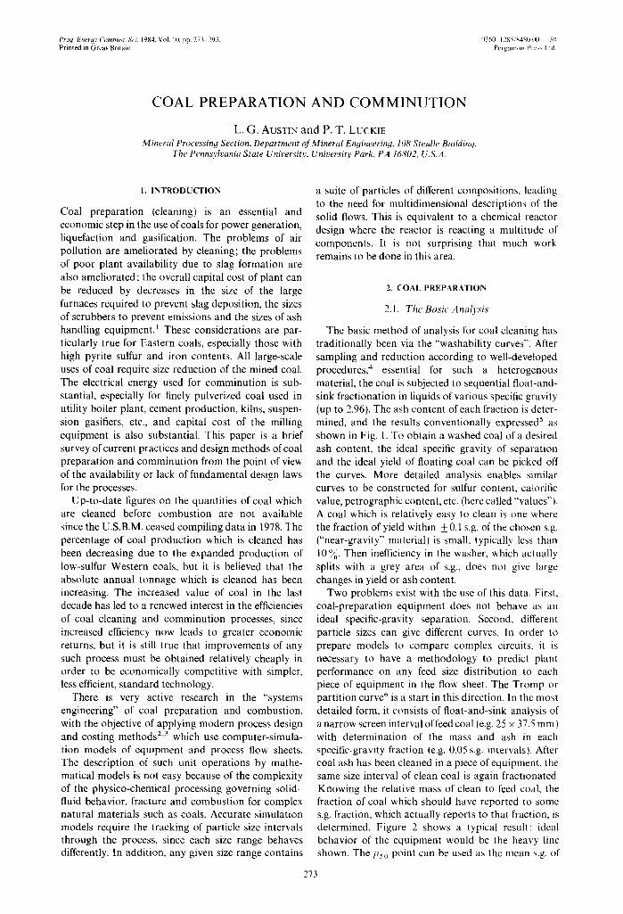
Two problems exist with the use of this data. First, coal-preparation equipment does not behave as an ideal specific-gravity separation. Second, different particle sizes can give different curves. In order to prepare models to compare complex circuits, it is necessary to have a methodology to predict plant performance on any feed size distribution to each piece of equipment in the flow sheet. The Tromp or partition curve 6 is a start in this direction. In the most detailed form, it consists of float-and-sink analysis of a narrow screen interval of feed coal (e.g. 25 × 37.5 ram) with determination of the mass and ash in each specific-gravity fraction (e.g. 0.05 s.g. intervals). After coal ash has been cleaned in a piece of equipment, the same size interval of clean coal is again fractionated. Knowing the relative mass of clean to feed coal, the fraction of coal which should have reported to some s.g. fraction, which actually reports to that fraction, is determined. Figure 2 shows a typical result: ideal behavior of the equipment would be the heavy line shown. The Pso point can be used as the mean s.g. of
273

274 L.G. AUSTIN and P. T. LUCKIE
S o
O z >- 1 0 - - I -
. D K
U 20 ~ L U W
40 -
6 0 - -
7 0 - -
E 7' ; ,"-
to,=,
I 0 0
2.10
0
C
A B
I I 2.00 1.90
2 4
0.7
0 10 20
I I I I I I I I I t i I I I I I
} .00 1 .70 i 1 .60 i 1.50 J 1.S|
J6 8.0Y. A I 10 12 1 ' I I j I
o.8 o.9 ! 1 . o 1.1 1 o . 9 6 ~ s i 30,0 % 40 50 60 ELEM. ASH
58.3% CUM. SINK
FIG. 1. Typical washability curves.
E
,it
u
C
1.40 1.30 SPECIFIC GRAVITY E,F 14 16 CUMULATIVE FLOAT A
ASH PERCENT
1.2 1.3 CUMULATIVE FLOAT B SULFUR
70 80 CUMULATIVE SINK C ASH AND ELEMEN. ASH PERCENT D
the equipment. The expression (P75- P25)/2 is used as an index of the imperfection of the actual machine fractionation. The sets of partition curves for each value of interest (mass, ash, C.V., etc.) and how they vary with feed size, method of operation, pretreatment of the coal in a prior piece of equipment, etc. form the model for the device.
Data in such detail is rarely available. If the curves for different sizes coincide, an overall partition curve is obtained; this is often approximately true for coarse coal cleaning. An ideally inefficient separation, i.e. simple splitting of the sample to floats and sinks, is a horizontal line on the plot. This tends to be ap- proached for very fine sizes, which simply follow the split of fluid. A device which promotes mixing will also give flatter partition curves. Consequently, clean- ing processes are usually performed for restricted
ranges of feed size, with the equipment operated in a manner which is optimum for that particular size range.
A simple expression for "cleaning efficiency" which is often used is based on the determination of the ash content (or any other value) of the known amount of actual float recovery. The ideal yield at this content (and thus the "effective" s.g. of the equipment) can be picked off Fig. 1. The efficiency is then
actual yield ~1 - (1)
ideal yield
This indicates the efficiency of the plant for the specified feed size and product quality (grade). Another simple efficiency, ~2, which could be used is the fractional recovery of calorific value (exclud- ing that due to oxidation of mineral matter). For
Coal preparation and comminution 275
100
75
50
25
Error Area __ /
-
PE = 1.67-1.43 __ ~ 2 = 0.12 __
' ~ I d e a l
. . . . q - - - 41-- C u t - Po in t - -
_o
. . . . _ l _ ~ _
0 t 1.2 1.4 I I 11.6 1.8 2.0 2.2 Speci f ic i 1.57 Gravi ty 1.43 1.67
2 . 4
F1o. 2. Tromp curve for Baum-Type Jig treating 125 mm x 0 coal.
this definition of fractional thermal recovery, ~2 goes down as grade goes up. The most important "efficiency", of course, is the maximization of profit for the plant as a whole, and this is not necessarily obtained for ~ and for ~2 at their maximums.
2.2. Heavy-Media Washers lor Coarse (150 mm × 7.5 ram) Coal Cleaninq
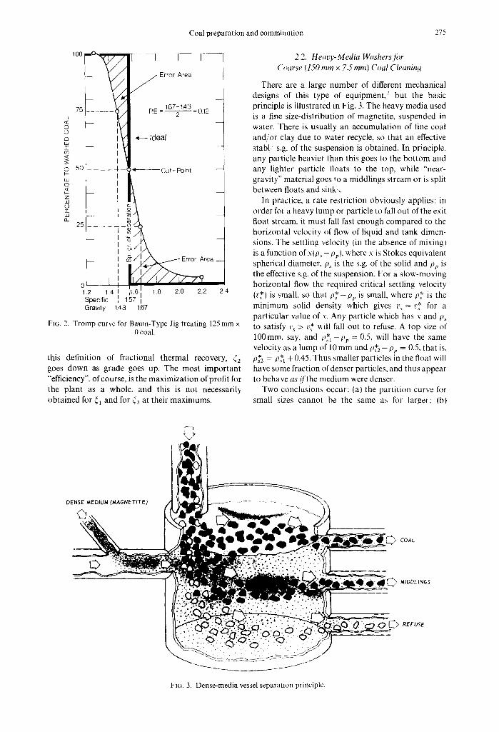
There are a large number of different mechanical designs of this type of equ ipment / but the basic principle is illustrated in Fig. 3. The heavy media used is a fine size-distribution of magnetite, suspended in water. There is usually an accumulation of fine coal and/or clay due to water recycle, so that an effective stabl s.g. of the suspension is obtained. In principle, any particle heavier than this goes to the bottom and any lighter particle floats to the top, while "near- gravity" material goes to a middlings stream or is split between floats and sink,.
In practice, a rate restriction obviously applies: in order for a heavy lump or particle to fall out of the exit float stream, it must fall fast enough compared to the horizontal velocity of flow of liquid and tank dimen- sions. The settling velocity (in the absence of mixing) is a function of x(p~ -#p) , where x is Stokes equivalent spherical diameter, P.4 is the s.g. of the solid and pp is the effective s.g. of the suspension. For a slow-moving horizontal flow the required critical settling velocity (v*) is small, so that p * - p p is small, where p* is the minimum solid density which gives t,~ = v* for a particular value of x. Any particle which has x and p~ to satisfy v~ > v* will fall out to refuse. A top size of 100mm, say, and t~*~-p~ = 0.5, will have the same velocity as a lump of 10 mm and P*2 - t )p = 0.5, that is, P*2 = P*t +0.45. Thus smaller particles in the float will have some fraction of denser particles, and thus appear to behave as i / the medium were denser.
Two conclusions occur: (a) the partition curve for small sizes cannot be the same as for larger: (bt
COAL
MIDDLINGS
REFUSE
FIG. 3. Dense-media vessel separation principle.

276 L.G. AUSTIN and P. T. LUCKIE
MEDIUM ENTERS,
/ '
lq
COAL ENTERS HERE
REFUSE EXITS HERE ~ FOR RINSING
MEDIUM RECOVERY
L SC~
COt
CLEAN COAL . . ~A~"/'P; .... EXITS HERE
MEOIUM ~ ~
EXIT HERE
\ MEDIUM RECOVERY
FIG. 4. Three-product dense-media vessel.
forcing the equipment to too-high flow rates (clean coal capacity) gives less efficient separation. The quantitative application of these apparently simple concepts for plant design is hampered by several factors. First, there is a fundamental problem in calcu- lating the buoyancy forces on a lump in a slurry. What is the correct s.g. to use for the slurry? A large heavy lump must force its way through liquid containing smaller particles of media and coal, thus displacing slurry. A smaller, lighter lump does not displace large lumps because they are falling faster, so it displaces a less-dense slurry, Thus the appropriate pp to use varies with the size and Ps being considered. There appears to be no satisfactory current treatment of this problem. Second, the volume concentrations of media + fine coal-clay are chosen to be low enough to avoid the well-known rapid increase of viscosity as concentration becomes too high, yet high enough to
TABLE I. Summary of performance data, dense medium (magnetite) separators, +¼-in ( + 6.3-ram) sizes
Plants
D E F G
Ash, ~o Feed 21.9 20.6 30.2 27.2 Clean Coal 2.1 4.8 2.5 7.4 Refuse 85.5 62.5 51.2 80.6
Actualrecovery, ~o 76.2 72.6 43.1 73.0 Theoretical recovery, ~o 76.3 74.4 46.8 73.2 Efficiency, °/o (~i) 99.8 97.6 92.1 99.7 Ash error, °/o 0.0 0.3 0.3 0.1 Float in refuse, ~ of product 1.2 9.4 7.3 1.4 Sink in clean coal, ~/o of product 0.1 1.9 1.6 0.8 Total misplaced material, 0.4 3.9 4.9 1.0
~o of feed Near-gravity, _+0.10 s.g. 5.0 15.0 50.8 3.8
material, ~o of feed
give the desired pp. These give solid concentrations in the hindered settling region, 8 and the treatments of settling and slurry rheology in this region as a function of concentration and particle size distribution are not well developed.
Fine-tuning of the operation of a washer is some- times accomplished by a controlled upward flow of liquid to counter-act the settling velocity. In addi- tion, there is substantial ancillary equipment such as washed vibrating screens, magnetic flocculators, magnetic separator-thickeners, and gravity thickeners, to wash the coal and refuse free from magnetite, recover the magnetite and recycle the correct density of slurry. Figure 4 shows one type of heavy-media washer; many other types are available, v with capaci- ties up to 500tph. Table 1 gives typical performance data: 7 overall ~1 efficiencies are high, indicating that p** - pp is small for the top sizes.
2.3. Jigs fi~r Coal Cleaning
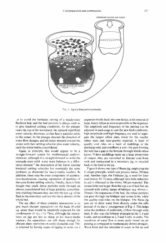
The basic principle of a jig is shown in Fig. 5. Water is cycled up and down through a bed of coal, either by movement of a plunger operated from a cam or by the equivalent use of cyclic air pressure to drive the water. Cycle frequencies are normally in the range of 4(~120c/min, with amplitude ranging from 40- 150 mm depending on the sizes being treated. Starting with a packed bed and the plunger just starting to move up, the upward superficial velocity of water through the bed increases as the plunger moves up, until the bed reaches incipient fluidization. As the plunger rises and velocity increases the bed expands and lifts from the screen, allowing larger, denser particles to fall with a counter-settling velocity, while lighter, smaller particles move more rapidly upward with less lag behind the water flow. The amplitude is
Coal preparation and comminution 277
DOWNWARD WATER~AIR SURGE
F~G. 5. Jig-washing action principle.
at to avoid the turbulent mixing of a steady-state fluidized bed, and the bed porosity is always such as to give hindered settling conditions. As the plunger nears the top of the movement, the upward superficial water velocity decreases, so that heavy particles settle to the screen. As the plunger decends the direction of water flow changes, and all lumps descend toward the screen with their settling velocities plus water velocity, until the whole bed is consolidated.
Again, in principle, this would appear to be a straight-forward system for mathematical analysis. However, although it is straight-forward to write the unsteady-state solid water mass balances in a differ- ential element, 9 the description of the forces causing hindered settling velocities has essentially the same problems as discussed for heavy-media washers. In addition, there may be some component of accelera- tion-deceleration, causing separation of particles of the same Stokes settling velocity. Finally, there is little dought that small, dense particles settle through an almost consolidated bed of large particles {consolida- tion trickling) because they see only the low s.g. of the fluid in the interstices and not the slurry density of the whole bed.
The net effect of these complex interactions is to give much sharper separations on the basis of solid s.g. alone than would be intuitively expected for the combination of x(p s - 1). Thus, although the separa- tions on jigs are not as sharp as for heavy-media washers, the separations are still sharp enough for efficient plant operation on easily cleanable coal. This is achieved by having stages of jigging in series via a
sequence of cells built into one device, with removal of large, heavy refuse as soon as possible in the sequence. The amplitude and frequency of the pulsing can be adjusted in each stage to suit the new feed conditions: high amplitude and high frequency are used to ~gre- gate the largest refuse sizes, lower for the smaller refuse sizes and near-gravity material. A layer of quality coal rides on a layer of middlings at the discharge end, and overflows a weir: the gate forming the weir has a gap at the bottom through which refuse leaves. If these middlings make up a large proportion of output, they are recrushed to liberate coal from rock and reseparated in a secondary jig, or recycled back to the feed to the jig.
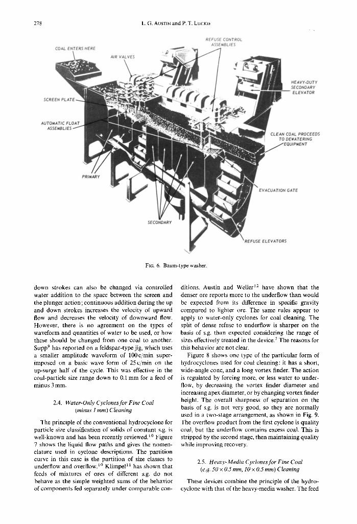
Figure 6 shows one type of Baum jig, employing the U-shape principle, which can process minus 200 mm coal. Another type, the Feldspar jig, is used for finer coal (minus 10 15 mm), although very little reduction in ash is obtained in the minus 300 ~tm material. The screen holes are larger than the top size of feed but are covered with slabby lumps of feldspar (e.g. 60 mm x 20 mm }. On expansion of the bed, the refuse particles can pass through the feldspar and screen holes, while the quality coal rides on the feldspar. The Batac jig uses air to drive water from directly under the cells instead of via the U arrangement of Fig. 5. This helps solve the problem of uniformity of flow through wide beds. II also uses the feldspar principle in the 3, 4 and 6 cells, and no feldspar in 1, 2 and 5 cells, in series. The waveform of water flow is more easily tuned via air pulsing as compared to mechanically driven plungers. Wave form and the velocities of water in the up and
278 L.G. AUSTIN and P. T. LUCKIE
COAL ENTERS HERE
AIR VALVES
REFUSE CONTROL ASSEMBLIES
~ ~ ~ ' ~ 7 ' ; ¸ .... ~ i ~;.:~;;~.~,!.;
HEAVY.DUTY SECONDARY ELEVATOR
AUTOMATIC FLOAT ASSEMBLIES /
CLEAN COAL PROCEEDS TO DEWATERING
/EQUIPMENT
PRIMARY
EVACUATION GATE
SECONDARY
FIG. 6. Baum-type washer.
EVATORS
down strokes can also be changed via controlled water addition to the space between the screen and the plunger action; continuous addition during the up and down strokes increases the velocity of upward flow and decreases the velocity of downward flow. However, there is no agreement on the types of waveform and quantities of water to be used, or how these should be changed from one coal to another. Supp 9 has reported on a feldspar-type jig, which uses a smaller amplitude waveform of 100c/min super- imposed on a basic wave form of 25 c/min on the up-surge half of the cycle. This was effective in the coal-particle size range down to 0.1 mm for a feed of minus 3 mm.
2.4. Water-Only Cyclones for Fine Coal (minus 1 mm) Cleaning
The principle of the conventional hydrocyclone for particle size classification of solids of constant s.g. is well-known and has been recently reviewed. A° Figure 7 shows the liquid flow paths and gives the nomen- clature used in cyclone descriptions. The partition curve in this case is the partition of size classes to underflow and overflow.l° Klimpel~a has shown that feeds of mixtures of ores of different s.g. do not behave as the simple weighted sums of the behavior of components fed separately under comparable con-
ditions. Austin and Weller 12 have shown that the denser ore reports more to the underflow than would be expected from its difference in specific gravity compared to lighter ore. The same rules appear to apply to water-only cyclones for coal cleaning. The split of dense refuse to underflow is sharper on the basis of s.g. than expected considering the range of sizes effectively treated in the device. 7 The reasons for this behavior are not clear.
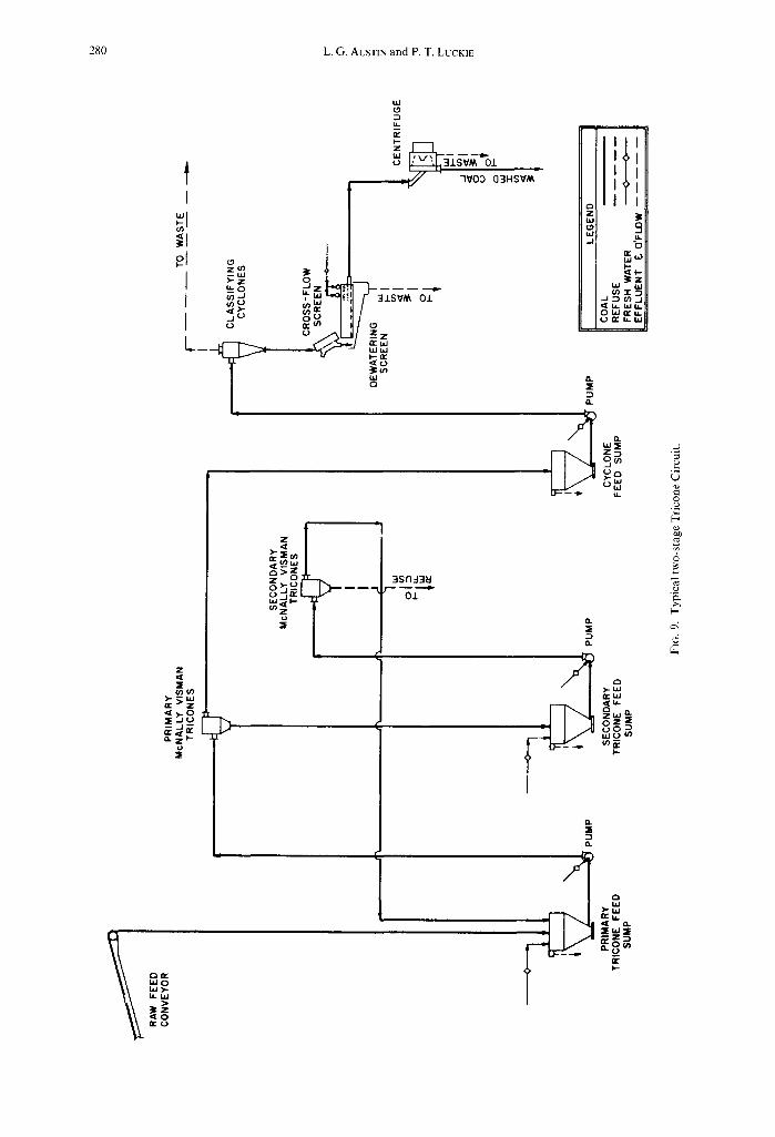
Figure 8 shows one type of the particular form of hydrocyclones used for coal cleaning: it has a short, wide-angle cone, and a long vortex finder. The action is regulated by forcing more, or less water to under- flow, by decreasing the vortex finder diameter and increasing apex diameter, or by changing vortex finder height. The overall sharpness of separation on the basis of s.g. is not very good, so they are normally used in a two-stage arrangement, as shown in Fig. 9. The overflow product from the first cyclone is quality coal, but the underflow contains excess coal. This is stripped by the second stage, then maintaining quality while improving recovery.
2.5. Heavy-Media Cyclones for Fine Coal (e.g. 50 x 0.5 mm, 10 x 0.5 ram) Cleaning
These devices combine the principle of the hydro- cyclone with that of the heavy-media washer. The feed

Coal preparation and comminution
Fine
Overflow discharge
~der
279
Pressurized slurr' enters tangentiall
Slurry rotation develops high centrifugal forces throughout cyclone
Fine particles inward and up spiralling vort{
Ooarse particles driven toward wall and downward in accelerating spiral
;pigot or apex
Underflow discharge Coarse
F]G. 7. The mode of operation of a cyclone.
CO, PU,
liquid normally used is a suspension of magnetite with a size distribution of 90 % minus 325 mesh (45 pro), in water at 25-30% by volume of magnetite and coal. The ratio of media to coal in the feed is in the range of 3 : 1 5 : 1. As might be expected, the sharpness of s.g. separation is greatly enhanced over the water-only cyclone, and the devices give sharp overall partition curves. Again, the systems are more costly than jigs, tables, etc., because of the ancillary equipment for media recovery. The coal feeds are normally "deslimed" over sieve bends and vibrating screens to avoid accumulation of excess fine coal and clay in the circuits. However, the systems work very efficiently for coals with high near-gravity material, and for effective s.g.'s as low as 1.3-1.4 (which are difficult to achieve with other washers).
Capacities are typically 50tph of coal for a single 50-cm diameter cyclone and 75tph for a 61-cm diameter. Research is underway to extend the top sizes, and to eliminate the need for desliming by improvements in the ancillary operations.
SINK PRODUCT EXIT
1:[o. 8. Cross-section view ofMcNally Visman Tricone.
2.6. Wet Concentrating Tables." Minus 10 mm Coal
This is the most widely used method of cleaning coal of the minus 10mm size. The principle is illus-
3PECS l / t : 2 -N
280 L.G. AUSTIN and P. T. LUCKIE
Z ~X
~-~w wO
~z ~eU
I
o l ,,
I u- 0 u ' ) ( J
I ~(" (,D
W l
;~/~-/ 7V03 G3HSVM m
Z
3 J.SVM O.L
l/ - z z , E U J
~ m W 0
a.
--'3 0..
w=E Z : 3 S~
, L ) 0 > ' W
~ ( n w O .o=l Z ) ' L ) m m
0.,I.
Q.
O.
a > - W r w W
o Z , , ¢ (..) 0 :~' w .U, (/') ~E"
I--
O.
,'1 ,,s
3 a .
W
. J
3
o o
.o
[-

Coal preparation and comminution 281
.++'+~ .--"
+/"
/ i
// (i •//
• //, /:
{ /
ct ?
/ j ,,!
i / • ; / . / + : . ;
# ; 0 ..
i ;
.... , ¸ , , i
-?WO~-J- - o y\ ~ ~ b / .'
l illl • :ilJ/'
0 4
MIDDLINGS COAL
FIG. 10. Cleaning table principle.
trated in Fig. 10. The table, traversed by ridges (tapered riffles), is slightly tilted in both directions away from the feed. Water is introduced all along the upper edge and allowed to flow down, across the deck, which is moved horizontally, at right angles to the flowing film, with a rapid movement from right to let and a slow return from left to right.
Since the velocity of the fluid is not the same at all depths of the film, the velocity at which a particle moves depends upon its specific gravity, the viscosiD of the fluid, the thickness of the film (which depends upon the rate of flow of the fluid) the slope of the deck (expressed as the critical angle below which motion of the particle does not occur) and the coefficient of friction between the particle and the deck. The as- symetrical longitudinal motion of the table causes the rate of travel of the particle to be affected by both its size and specific gravity. Analytical mathematical treatment is only possible with some very simplifying assumptions. As a result of these effects, it has been observed that the travel is along a diagonal line beginning at the feed point. The riffles increase the capacity of the table as well as providing troughs where hindered settling can occur. Because of the stratification behind the riffles and the assymetrical acceleration of the deck, the heavier particles travel towards the side edge.
The modern table is a fixed size, 11 m on the side edge, 23m on the top edge, rhomboidally shaped. Hence, it is of fixed capaci ty--a nominal 10tph, increasing to 15tph for coarser feed, decreasing to 7.5 tph for finer feed. The table is suspended on cables and can be purchased as a single, double or triple layer installation.
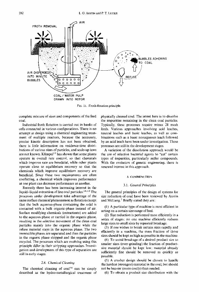
2.7. Froth Flotation: Minus 0.5 mm
The principle of froth flotation is illustrated in Fig. 11. A froth-flotation cell is rapidly stirred, and air flow into the impeller, plus a frothing agent, generates a mixture of slurry and bubbles. A suitable concentra- tion of collector is maintained in the cell: this chemical adsorbs on the surface of coal and makes it more hydrophobic, so that a coal air bubble interface is thermodynamically preferred over a solid water interface. Thus bubbles attach to the coal particles and float then to the surface, leaving particles of mineral matter in the bottom. The froth on the surface, containing the cleaned coal, is moved over the lip of the tank by slow paddles.
The types and concentration of chemicals used for froth and collector are tested in small laboratory- batch cells. There is a wide literature on the theories of the surface chemistry involved in the adsorption of collectors and their effect on bubble attachment. The carrying of attached particles to the top of a cell is a rate process which is roughly first-order for homo- geneous material (e.g. pure coal o1 pure silica) of a given particle size. The rate falls for large particles and for very small particles (e.g. minus 20jim). In a material with a matrix of coal-ash flotation properties. even for material screened to a single screen-interval size, the material reaching the top of the cell after a period of flotation is the net production of all rate classes. However, precise analysis of coal flotation as a mult i-component rate process is seldom performed: chemicals are selected on the basis of maximum recovery of a desired grade (ash content), providing flotation rates are reasonable, by a lumped test on the
282 L.G. AUSTIN and P. T. LUCKIE
. , p AiR FROTH REMOVAL ,,=,
' i i . ,
/ !i:2;';'i':';:::/'ii':!:i'" ~ _ _ . I "i;i;i::.:i;;;'(;.~:~' ~ B U B B L E S A D H E R I N G
COAL / WATER PULP DRAWN INTO ROTOR
FIo. 11. Froth-flotation principle.
complete mixture of sizes and components of the feed coal.
Industrial froth flotation is carried out in banks of cells connected in various configurations. There is no attempt at design using a chemical engineering treat- ment of multiple reactors, because the necessary, precise kinetic description has not been obtained, there is little information on residence-time distri- butions of various sizes of particles, and scale-up laws are not known. KlimpeP ~ has shown that some plants operate in overall rate control, so that chemicals which improve rate are beneficial, while other plants operate close to equilibrium recovery so that the chemicals which improve equilibrium recovery are beneficial. Since these two requirements are often conflicting, a chemical which improves performance at one plant can decrease performance at another.
Recently there has been increasing interest in the liquid-liquid extraction of fine coal particles.14'1 s The processes under development take advantage of the same surface chemical phenomenon as flotation except that the bulk aqueous-phase containing the solid is contacted with a bulk organic-phase instead of air. Surface modifying chemicals (extractants) are added to the aqueous phase or carried in the organic phase, resulting in the selective movement of the clean coal particles mainly into the organic phase while the refuse material stays in the aqueous phase. The two immiscible phases are separated and then the particles in the organic phase stripped and the organic phase recycled. The processes which are evolving using this principle differ in their stripping approaches. Investi- gation and development of this type of separation are still in early stages.
2.8. Chemical Cleanin9
The chemical cleaning of coal 16 can be simply described as the hydro-metallurgical treatment of
physically cleaned coal. The intent here is to dissolve the impurities remaining in the clean coal particles. Typically, these processes require minus 28 mesh feeds. Various approaches involving acid leaches, neutral leaches and basic leaches, as well as com- binations such as a basic nonaqueous leach followed by an acid leach have been under investigation. These processes are still in the development stages.
A variation of the dissolution approach would be the use of selective bacterial agents to "eat" certain types of impurities, particularly sulfur compounds. With the evolution of genetic engineering, there is renewed interest in this approach.
3. COMMINUTION
3.1. General Principles
The general principles of the design of systems for size reduction of coal have been reviewed by Austin and McLung. 7 Briefly stated they are:
(1) A particular type of machine is most efficient in acting on a certain size range of feed.
(2) Size reduction is performed most efficiently in a series of stages: no one machine efficiently reduces large sizes to small sizes by repeated breakage.
(3) If one wishes to break certain sizes rapidly and efficiently in a machine, the mass fraction of those sizes should be kept as high as possible in the machine.
(4) To avoid breakage of a desired product size to smaller sizes (over-grinding) the fraction of product- size material should be kept low: material already sufficiently fine should be removed as quickly as possible.
(5) A crusher design should be chosen to handle the hardest (strongest) material in the coal, but should not be heavier (more costly) than needed.
(6) To obtain a product size distribution with the
Coal preparation and comminution 283
minimum of fines the mill should be in closed circuit with a high circulation ratio through an efficient classifier.
(7) Output is increased and specific grinding energy reduced only when a closed circuit is operated to give a steeper size distribution (less fines) for a desired top size.
The quantitative application of these rather com- mon-sense rules is not well developed, but the follow- ing sections review progress made in this direction.
3.2. Crushers
Crushers accept run-of-mine coal and reduce it to sizes suitable for cleaning or use in relatively large sizes, or as feeds for pulverizing. There are many types and makes of crushers for coal, v including jaw crushers; single-, double- and triple-roll crushers with smooth, ribbed or toothed rolls; impact crushers; rotating-cage crushers; etc., etc. Most designs have been in existence for many years and have reached an advanced state of mechanical reliability. They are sized for capacity using the empirical experience of the manufacturers on different coals, it is normally suffi- cient to make a coarse distinction of coal type into soft, medium and hard (better terms are weak, medium and strong). The machines have high capa- city for relatively low capital investment and energy consumption, so there has been little incentive to develop precise capacity-sizing methods or optimize performance. Recent developments have been mainly in the area of cheaper methods of construction, use of stronger and more abrasion resistant materials, and reduction of cost by matching the strength of con- struction with the ease of breakage of the coal.
On the other hand, application of the concept of constructing simulation models for coal-cleaning plant or fine-pulverizing units requires a reasonably exact knowledge of the size distributions produced by crushers, and how they vary with coal type and operating conditions. There is only sparse information in this respect, and it is certainly not possible at the moment to compare, for example, the production of fines as a function of coal type, ash content, type of crusher and mode of operation of the crusher.
Austin et al.l 7.~ 8 have demonstrated a methodology of analysis of breakage in double-roll crushers, which enables the prediction of the product size distribution as a function of feed size distribution and gap setting between the rolls. The method has been adapted for gyratory crushers and, with modification appropriate for each machine, could possibly form a basis for models for many types of crushers.
The basic assumptions of the model are:
(11 The breakage of material of each size interval
(x/'2 screen sequence) occurs independently of other material.
(2) Provided the rolls are large in diameter com- pared to the feed sizes and the gap, then the product
I . O ~ - - ] I ..... ~ F T 7 0
~ ' \ 0 x~- 12 mesh (170mm) ~ i k
u_ 05 ~ 05
10 14 2 0 2.8 4 0 5 7
RELATIVE SIZE xi/xg
FIG. 12. By-pass fractions obtained by varying breakage size at constant gap or breaking constant size with variable gap.
size distribution for breaking a single size depends on the ratio of the size to the gap.
(3) The description of the overall breakage of a single feed size is made up of:
(a) the set of fragments produced by primary fracture
(b) the fraction of the feed which passes through the gap without breaking (primary by-pass)
(c) the fraction of primary fragments of each size which by-pass without further fracture (secondary by-pass)
(d) an algorithm to describe repeated fracture and by-pass until all feed material has passed through the gap.
(4) A dimensionally normalized set of primary frag- ments, i.e. a fixed fraction of product material less than, say, half of the starting size, independent of the starting size.
These assumptions have all been verified experi- mentally. They were incorporated into a simple com- puter model for prediction of product-size distribution for any feed size distribution through any gap setting. Input to the program requires the values of the characteristic primary breakage fragments and by- pass fractions, determined for a coal in simple labora- tory tests in a small roll crusher.
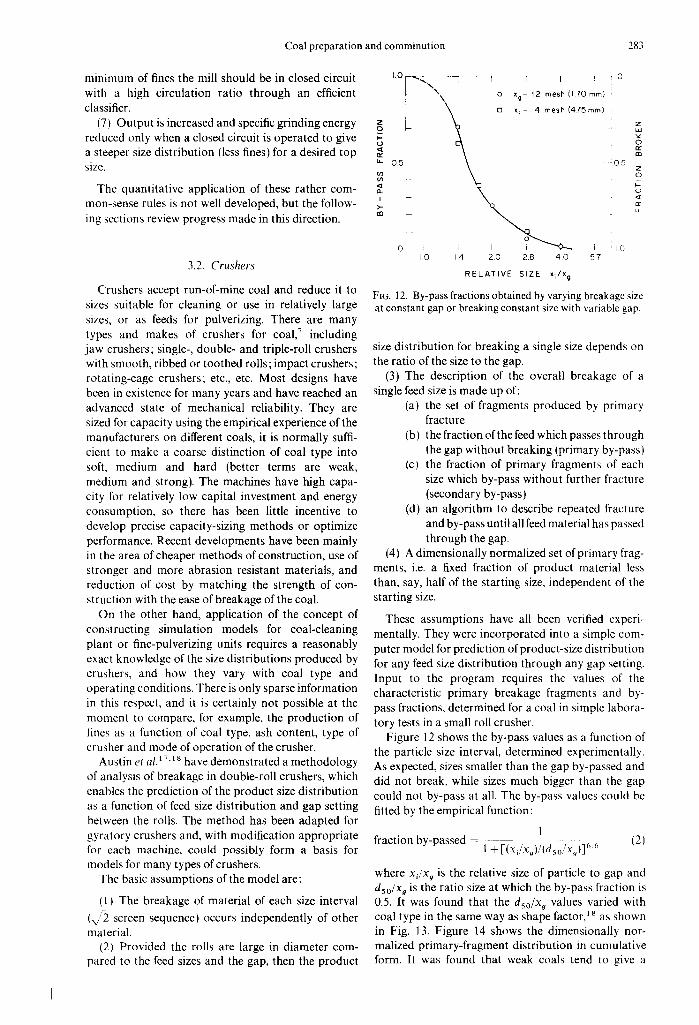
Figure 12 shows the by-pass values as a function of the particle size interval, determined experimentally. As expected, sizes smaller than the gap by-passed and did not break, while sizes much bigger than the gap could not by-pass at all. The by-pass values could be fitted by the empirical function:
1 fraction by-passed = 1 +[(xjxg)/(dso, . /x , )] ~'-~ (2)
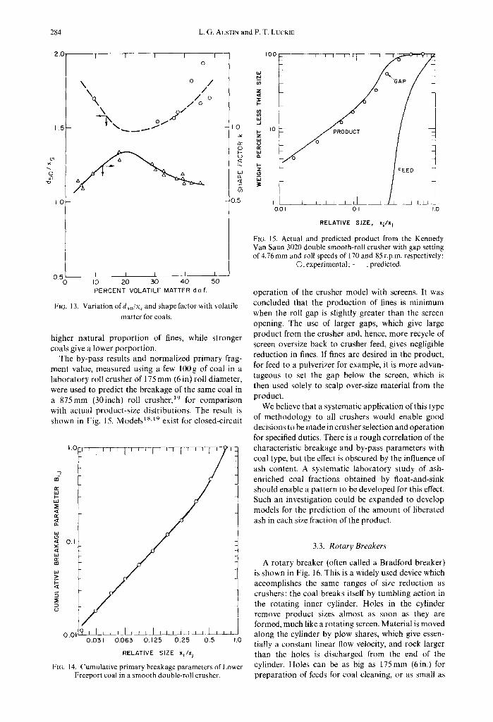
where x j x o is the relative size of particle to gap and dso/X o is the ratio size at which the by-pass fraction is 0.5. It was found that the dso/X o values varied with coal type in the same way as shape factor, 18 as shown in Fig. 13. Figure 14 shows the dimensionally nor- malized primary-fragment distribution in cumulative form. It was found that weak coals tend to give a
284 L.G. AUSTIN and P. T. LUCKIE
2.0
0 if)
1.5
1.0
I I I I 0
\ o /
/ o / o
\ 2 /
0.5 I I I I 0 10 20 30 4 0
PERCENT VOLATILE MATTER da.f .
- I O
ri- O
c)
¢D
05
I 50
FIG. 13. Variation ofdso/X ~ and shape factor with volatile matter for coals.
higher natural proport ion of fines, while stronger coals give a lower porportion.
The by-pass results and normalized primary frag- ment value, measured using a few 100g of coal in a laboratory roll crusher of 175 mm (6 in) roll diameter, were used to predict the breakage of the same coal in a 875mm (30inch) roll crusher, 19 for comparison with actual product-size distributions. The result is shown in Fig. 15. Models1 s,~9 exist for closed-circuit
1 .0 J 1 ' +' I " ' ; I
g
o.o119 J I ~ . _ L i r ~ I , J , L ~ _ ~ , ~ 0 . 0 3 1 0 . 0 6 3 0 . 1 2 5 0 . 2 5 0 . 5 1.0
RELATIVE SIZE x i / x j
Ft(~. 14. Cumulative primary breakage parameters of Lower Freeport coal in a smooth double-roll crusher.
I 0 0 T ~ - ~ - , , rT T
I ~- l I ~ 1 1 I 0.01 0.1 1.0
RELATIVE SIZE, x i /x I
FIG. 15. Actual and predicted product from the Kennedy Van Saun 3020 double smooth-roll crusher with gap setting of 4.76 mm and roll speeds of 170 and 85 r.p.m, respectively:
O, experimental;+- , predicted.
operation of the crusher model with screens. It was concluded that the production of fines is minimum when the roll gap is slightly greater than the screen opening. The use of larger gaps, which give large product from the crusher and, hence, more recycle of screen oversize back to crusher feed, gives negligible reduction in fines. If fines are desired in the product, for feed to a pulverizer for example, it is more advan- tageous to set the gap below the screen, which is then used solely to scalp over-size material from the product.
We believe that a systematic application of this type of methodology to all crushers would enable good decisions to be made in crusher selection and operation for specified duties. There is a rough correlation of the characteristic breakage and by-pass parameters with coal type, but the effect is obscured by the influence of ash content. A systematic laboratory study of ash- enriched coal fractions obtained by float-and-sink should enable a pattern to be developed for this effect. Such an investigation could be expanded to develop models for the prediction of the amount of liberated ash in each size fraction of the product.
3.3. Rotary Breakers
A rotary breaker (often called a Bradford breaker) is shown in Fig. 16. This is a widely used device which accomplishes the same ranges of size reduction as crushers : the coal breaks itself by tumbling action in the rotating inner cylinder. Holes in the cylinder remove product sizes almost as soon as they are formed, much like a rotating screen. Material is moved along the cylinder by plow shares, which give essen- tially a constant linear flow velocity, and rock larger than the holes is discharged from the end of the cylinder. Holes can be as big as 175mm (6in.) for preparation of feeds for coal cleaning, or as small as

Coal preparation and cornminution 285
FIG, 16. Twelve-feet diameter Rotary Breaker.
38mm (1½in.) for leeds to pulverizers. They have the advantages of simplicity and low maintenance, low fines production and some degree of cleaning.
Difficulty has been experienced in the accurate pre- diction of capacity of this type of breaker and, again, there has been no way of predicting the product size distribution. Austin and Luckie 2° have developed a mathematical model for rotary breakers, based on measuring the rates of self-breakage of tumbling coal by batch tests in a laboratory rotating cylinder of 1400-mm (4 It) diameter. The model uses the concepts of first-order breakage and specific rate of breakage, embodied in the relation
rate of disappearance of size interval./ = SiwjW (31
where W is the total weight of coal, wj is the fraction of this of size j and S i is the specific rate of breakage (fraction per unit time) of size j. This relation applies to a fully-mixed reactor, and breakage again gives a set of primary fragments, thus producing material in smaller size intervals:
"rate of appearance of size i = sum rate of production from all larger sizes - rate of breakage of size i'"
i 1
= - & w ~ W + ~ b~.jS/wjW (4) j i
where 1 is used for the top size interval, 2 the next and
so on, and b~.j is the fraction of primary fragments of sizej which falls into size i.
The model applies this relation (for each size inter- val) to a differential element along the cylinder, with mass flow in and out of the element, and rapid removal of sizes less than the holes. The laboratory batch tests characterized Sj and B~) as a function of size, size consist, fractional loading of the c~linder with solid, and a scale-up law is used to predict S i values for any diameter of cylinder. Numerical solution of the resulting differential equation, allowing for the change in Sj due to decrease of filling along the cylinder, gives the maximum capacity at which the dis- charge end of the cylinder is essentially free from coal, thus discharging only liberated large rock. The solu- tion also gives, of course, the product-size distribution of the material passing through the holes.
This model is still in the process of being validated against a full-scale trial, although it has already pre- dicted the correcl order of magnitude of plant capaci- ties. However, as with any simulation model, it ha~ to be made sufficiently realistic to be of predictive use. Several factors remain to be incorporated into the model. Very weak coals break so rapidly at such high capacity that the product sizes are not immediately removed, much like an overloaded rotary sieve. Accumulation of fine sizes cushion the breakage action. Strong clean coal, especially of relatively small
286 L.G. AUSTIN and P. T. LUCKIE
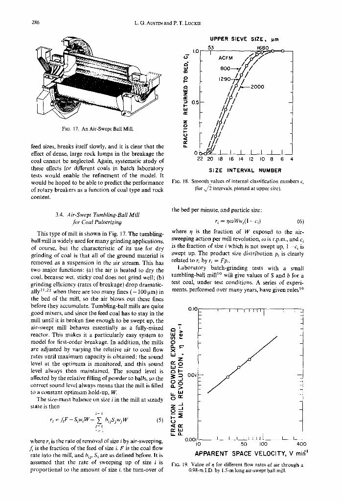
FIG. 17, An Air-Swept Ball Mill.
feed sizes, breaks itself slowly, and it is clear that the effect of dense, large rock lumps in the breakage the coal cannot be neglected. Again, systematic study of these effects for different coals in batch laboratory tests would enable the refinement of the model. It would be hoped to be able to predict the performance of rotary breakers as a function of coal type and rock content.
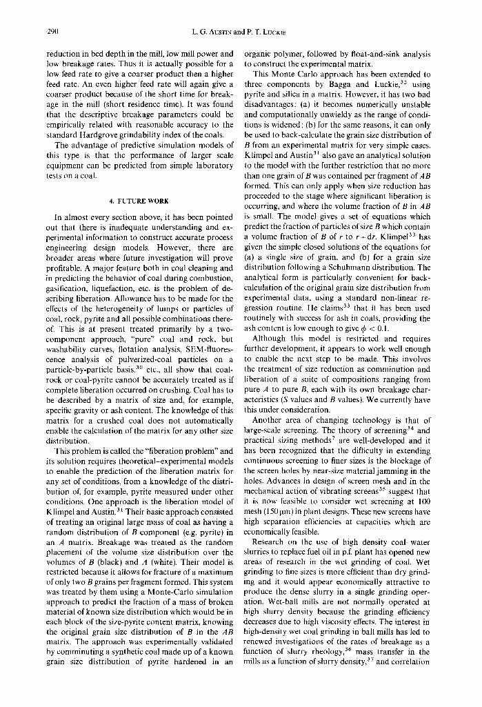
UPPER SIEVE SIZE, pm
1.0-' 53 1680_
~- ACFM
,,,°" 8007~/// ¢I)
o , ,07 ,', 2000 u.i =° /// m 0.5 ,., #/
,,"~-9 =<o ..I//~//11 ~ / I I I I ] I [ 0
22 20 18 16 14 12 I0 8 6 4
SIZE INTERVAL NUMBER
FIG. 18. Smooth values of internal classification numbers c~ (for x/2 intervals, plotted at upper size).
3.4. Air-Swept Tumbling-Ball Mill for Coal Pulverizing
This type of mill is shown in Fig. 17. The tumbling- ball mill is widely used for many grinding applications, of course, but the characteristic of its use for dry grinding of coal is that all of the ground material is removed as a suspension in the air stream. This has two major functions: (a) the air is heated to dry the coal, because wet, sticky coal does not grind well; (b) grinding efficiency (rates of breakage) drop dramatic- ally 21'22 when there are too many fines ( - 1001am) in the bed of the mill, so the air blows out these fines before they accumulate. Tumbling-ball mills are quite good mixers, and since the feed coal has to stay in the mill until it is broken fine enough to be swept up, the air-swept mill behaves essentially as a fully-mixed reactor. This makes it a particularly easy system to model for first-order breakage. In addition, the mills are adjusted by varying the relative air to coal flow rates until maximum capacity is obtained: the sound level at the optimum is monitored, and this sound level always then maintained. The sound level is affected by the relative filling of powder to balls, so the correct sound level always means that the mill is filled to a constant optimum hold-up, W.
The size-mass balance on size i in the mill at steady state is then
i - 1
r, =f t -S ,w,W+ ~ b,jSjwjW (5) j - 1 i > 1
where r~ is the rate of removal of size i by air-sweeping, f~ is the fraction of the feed of size i, F is the coal flow rate into the mill, and b~, S~ are as defined before. It is assumed that the rate of sweeping up of size i is proportional to the amount of size i, the turn-over of
the bed per minute, and particle size:
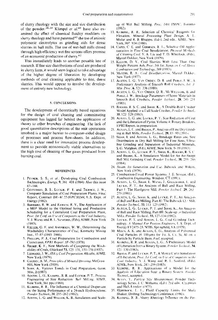
ri = rl~Wwi(1 - ci) (6)
where r/ is the fraction of W exposed to the air- sweeping action per mill revolution, o~ is r.p.m., and c~ is the fraction of size i which is not swept up, 1 - c~ is swept up. The product size distribution Pi is clearly related to ri by ri = Fpi.
Laboratory batch-grinding tests with a small tumbling-ball mill ~° will give values of S and b for a test coal, under test conditions. A series of experi- ments, performed over many years, have given rules ~°
Q
0 Q. X bJ
al--
0
r~bj 1,0..
0.I0
z
o.o,
0.001 i i I0
APPARENT
I I t t I I l l ] l l
/ / I
, , , ~ , 1 1 I I I 50 IO0 400
SPACE V E L O C I T Y , V m i 6 I
FIG. 19, Value of q for different flow rates of air through a 0.98-m I.D. by 1.5-m long air-swept ball mill.

Coal preparation and comminution 287
la.I N
Z
- r I - - o ' ) t fJ h i --.I I - - Z w (..) n.." I..iJ o..
I . - " i - (.9
LI.I
I 0 0
I 0 - -
I - -
,, -jT
o 7 /
/ i/2 o .4"
1 I I I l l l l I I I I I I I 1 [ I I I I I l l
aoo ~ 0 0 0 ~0000
SIEVE SIZE, pm
FIG. 20. Results of batch grinding 75-kg Belle Ayre coal in pilot-scale mill.
for converting the S values to other mill conditions (ball load, powder load, rotational speed, ball size mixture and density, etc.) and scale-up to other mill diameters; the b values are relatively independent of mill conditions. Austin et al. (23~ performed trials in a pilot-scale mill (3-ft diameter by 5-ft long), in which the mill and flows were suddenly stopped (in ¼ revolution) and the contents sampled. It was found that the contents were almost perfectly mixed and that the hold-up W corresponded exactly to the concct optimum powder filling level predicted from batch laboratory tests. (Too low a filling gives "steel ball-on- steel ball contact" without causing powder breakage,
~00
h i N
Z
I I'-- t y) 03 bJ J
D-- IC z b.I
IT I.iJ n
I-- "l-
I.iJ
I
T HROOr_POT i Ib /h k g / h
-- O EXPERIMENTAL 2 5 8 0 I O 8 0
(SMOOTHED)
_ _ S IMULATED 2 3 8 5 1083,
(W = 1 6 0 Ib) ~,
IO0 tO00
S I E V E S I Z E , p m
i
I ~ IO000
F1G. 21. Comparison of experimental results and computed resuhs; mill hold-up 1601bs (73kg), air flow rate 1290
ACFM (0.61 m3/sec)at 150°F (66°C).
too high gives "cushioning" caused by excess powder between balls, and, hence, inefficient breakage.) The measured values of Pi, wi, co, W and F enabled the calculation of ~/and q values.
The values of q are shown in Fig. 18, and ~/ as a function of air flow rate is shown in Fig. 19. Figure 20 shows the accuracy of the scale-up procedure for S values: the simulated lines are based on scale-up of S values, from tests on 120 g of coal in a mill of 200 mm diameter with 25 mm balls, to the size and ball mix of the large mill, inserted into the computer solution 1° for a batch grinding (unsteady-state) model. The experimental lines are actual batch grinding results in the pilot mill with 73 kg of coal.
The combination of relations for q and c~ with eqs 5 and 6 gives a model for the system, again pro- grammed for sequential (starting with the top size) solution by computer. Figure 21 shows the predictions of the model compared to the actual steady-state continuous mill data. The model was used to predict capacities in normal closed circuit throt}gh an air classifier (requiring a knowledge of classifier behavior as a function of air flow rate). The results are shown in Figs 22 and 23.
Although very encouraging, the work is not yet complete. First, although the laws for scale-up of breakage are known, the variation of ~/ with mill diameter is not known. Second, a systematic study needs to be performed of the effects of coal type, moisture content and ash content on S and B values. If this work were performed, the model would amount to a good simulator of this unit operation as a function of conditions of design and operation.

288 L.G. AUSTIN and P. T. LUCKIE
I00
-I- (/) hi
o 9o o o,J
z
O9
(3- 8O
I-- Z W 0 n," LI.I rl
70
I t I I I I
0
0 EXPERIMENTAL SIMULATION
I I I I I I 800 I000 1200
CIRCUIT PRODUCT R A T E , IbS/h
1400
FIG. 22, Comparison of experimental and predicted fineness of grinding for Belle Ayre coal ground closed-circuit in the
pilot-scale mill.
3.5. Roller Mills
The most widely used mills for pulverizing coal 24'25 are vertical mills where coal is crushed between loaded rollers or balls and a rotating table; two types are illustrated in Figs 24 and 25. Coal feeds onto a rotating table and is thrown by centrifugal force under heavily loaded rollers. The crushed coal is swept up in
J 600
d ~4o{
u~ 120(
o Q. {._ I000
800
I I I I 1 I
O EXPERIMENTAL PREDICTED / . ~ O , ' / _
~0 I I 1 I I I
600 800 I000 1200 1400 1600 1800 2000
AIR FLOW RATE, ACFM
FIG. 23. Circuit capacity vs dry flow rate for Belle Ayre coal ground in the pilot-scale mill.
an annular air flow, coarsest particles fall back for regrinding, and the suspended coal is passed through an air classifier (separator) where the coarser particles are rejected back to the table, and the final product coal-air suspension leaves the mill. Different mills vary in mechanical design, but especially in the form and contact of the rollers and table.
The most extensive attempt to construct predictive models for this type of mill is that of Austin et al.26 29 considering the Babcock E-type mill illus- trated in Fig. 25. Application of similar concepts of breakage principles to those discussed in the previous section gave results such as those shown in Fig. 26 for a pilot-scale mill. The special characteristic of this type of mill is that low feed rates to the mill cause a
Fan
Convertel
DE
De
Journ,
Pres
Air P
ng
Liner
)ly
ut
Obser
FIG. 24. C-E Raymond Roller mill.

Coal preparation and comminution 289
COAL*. I + , I:" "'+ AIR t I I
~ \ '-.: LOADtNG RING
CRUSHING BALLS
,, ~ ~
P[ FNL M
DRIVE
FIG. 25. Babcock El.7 mill.
RACE ON ROTATING TABL}
w
z "r,
100
]0
tb/h
,ii; .....
::¢':::":":""'" d
Coal Ib/h ACFM
• 875 900
• 360 89O
• 1660 790
1 I' 1 I I 10 1 O0 1 0 0 0 10,OOO
Sieve size, /Jm
FIG. 26. Results of grinding Lower Freeport coal (HGI = 88) in El.7 pilot-scale mill with 50{~o vane setting on classifier: solid lines are simulated values.
290 L.G. AUSTIN and P. T. LUCKIE
reduction in bed depth in the mill, low mill power and low breakage rates. Thus it is actually possible for a low feed rate to give a coarser product then a higher feed rate. An even higher feed rate will again give a coarser product because of the short time for break- age in the mill (short residence time). It was found that the descriptive breakage parameters could be empirically related with reasonable accuracy to the standard Hardgrove grindability index of the coals.
The advantage of predictive simulation models of this type is that the performance of larger scale equipment can be predicted from simple laboratory tests on a coal.
4. FUTURE WORK
In almost every section above, it has been pointed out that there is inadequate understanding and ex- perimental information to construct accurate process engineering design models. However, there are broader areas where future investigation will prove profitable. A major feature both in coal cleaning and in predicting the behavior of coal during combustion, gasification, liquefaction, etc. is the problem of de- scribing liberation. Allowance has to be made for the effects of the heterogeneity of lumps or particles of coal, rock, pyrite and all possible combinations there- of. This is at present treated primarily by a two- component approach, "pure" coal and rock, but washability curves, flotation analysis, SEM-fluores- cence analysis of pulverized-coal particles on a particle-by-particle basis, 3° etc., all show that coal- rock or coal-pyrite cannot be accurately treated as if complete liberation occurred on crushing. Coal has to be described by a matrix of size and, for example, specific gravity or ash content. The knowledge of this matrix for a crushed coal does not automatically enable the calculation of the matrix for any other size distribution.
This problem is called the "liberation problem" and its solution requires theoretical-experimental models to enable the prediction of the liberation matrix for any set of conditions, from a knowledge of the distri- bution of, for example, pyrite measured under other conditions. One approach is the liberation model of Klimpel and Austin.31 Their basic approach consisted of treating an original large mass of coal as having a random distribution of B component (e.g. pyrite) in an A matrix. Breakage was treated as the random placement of the volume size distribution over the volumes of B (black) and A (white). Their model is restricted because it allows for fracture of a maximum of only two B grains per fragment formed. This system was treated by them using a Monte-Carlo simulation approach to predict the fraction of a mass of broken material of known size distribution which would be in each block of the size-pyrite content matrix, knowing the original grain size distribution of B in the AB matrix. The approach was experimentally validated by comminuting a synthetic coal made up of a known grain size distribution of pyrite hardened in an
organic polymer, followed by float-and-sink analysis to construct the experimental matrix.
This Monte Carlo approach has been extended to three components by Bagga and Luckie, 32 using pyrite and silica in a matrix. However, it has two bad disadvantages: (a) it becomes numerically unstable and computationally unwieldy as the range of condi- tions is widened; (b) for the same reasons, it can only be used to back-calculate the grain size distribution of B from an experimental matrix for very simple cases. Klimpel and Austin 31 also gave an analytical solution to the model with the further restriction that no more than one grain of B was contained per fragment of AB formed. This can only apply when size reduction has proceeded to the stage where significant liberation is occurring, and where the volume fraction of B in AB is small. The model gives a set of equations which predict the fraction of particles of size B which contain a volume fraction of B of r to r+dr. Klimpe133 has given the simple closed solutions of the equations for (a) a single size of grain, and (b) for a grain size distribution following a Schuhmann distribution. The analytical form is particularly convenient for back- calculation of the original grain size distribution from experimental data, using a standard non-linear re- gression routine. He claims 33 that it has been used routinely with success for ash in coals, providing the ash content is low enough to give ~b < 0.1.
Although this model is restricted and requires further development, it appears to work well enough to enable the next step to be made. This involves the treatment of size reduction as comminution and liberation of a suite of compositions ranging from pure A to pure B, each with its own breakage char- acteristics (S values and B values). We currently have this under consideration.
Another area of changing technology is that of large-scale screening. The theory of screening 34 and practical sizing methods 7 are well-developed and it has been recognized that the difficulty in extending continuous screening to finer sizes is the blockage of the screen holes by near-size material jamming in the holes. Advances in design of screen mesh and in the mechanical action of vibrating screens 35 suggest that it is now feasible to consider wet screening at 100 mesh (150 jam) in plant designs. These new screens have high separation efficiencies at capacities which are economically feasible.
Research on the use of high density coal-water slurries to replace fuel oil in p.f. plant has opened new areas of research in the wet grinding of coal. Wet grinding to fine sizes is more efficient than dry grind- ing and it would appear economically attractive to produce the dense slurry in a single grinding oper- ation. Wet-ball mills are not normally operated at high slurry density because the grinding efficiency decreases due to high viscosity effects. The interest in high-density wet coal grinding in ball mills has led to renewed investigations of the rates of breakage as a function of slurry rheology, 36 mass transfer in the mills as a function of slurry density, 37 and correlation
Coal preparation and comminution 291
of slurry rheology with the size and size distr ibution of the p o w d e r ) 8'a9 Klimpel et al. 4° have also ex-
amined the effect of chemical fluidity modifiers on slurry rheology and have patented 4I the use of anionic polymeric electrolytes as grinding aids for dense slurries in ball mills. The use of wet-ball mills closed through high-efficiency wet fine screens offers promise of an economic product ion of slurry. 42
This immediately leads to another possible line of research. If fine size distributions of coal are produced in slurry form, it would seem logical to take advantage of the higher degree of liberation by developing
methods of coal cleaning applicable to fine, dense slurries. This would appear to involve the develop- ment of entirely new technology.
5. CONCLUSIONS
The development of theoretically based equations for the design of coal cleaning and comminut ing equipment has lagged far behind the application of theory to other branches of engineering. The lack of good quanti tat ive descriptions of the unit operations involved is a major barrier to computer-aided design
of processes and process flow-sheets. In addition, there is a clear need for innovative process develop-
ment to provide economically viable alternatives to the high cost of cleaning of flue gases produced from burning coal.
REFERENCES
1. PENNER, S. S., et al., Developing Coal Combustion Technologies, Enerqy, 9, 361 418 (1984). Also this issue 87 144.
2. GOTTFRIED, B. S., LUCK1E, P. T. and TIERNEY, J. W., Computer Simulation of Coal Preparation Plants, Final Report, Contract DE-AC22-80PC30144, U.S. Dept. of Energy (1982l.
3. BARBARO, R. W. and RAMANI, R. g., The Application of a MIP Model to the Optimal Siting and Production Scheduling for a Centralized Coal Preparation Plant, Proe. 1st Con]'. on Use ol'Computers in the Coal Industry, Y. J. WANG and R. L. SANFORD, (Eds), AIME, New York (1983].
4. KELLER, G. E. and ANDERSON, W. W., Determining the Washability Characteristics of Coal, Kentucky Mining Inst., 37 -83 (1945 1946).
5. PHILLIPS, P. J., Coal Preparation for Combustion and Conversion, EPRI Report AF-791 (1978).
6. TROMP, K. F., New Methods of Computing the Wash- ability of Coals, Gltickauf73, 125 131,151-156 (1937L
7. LEONARD, J. W., (Ed.), Coal Preparation, 4th edn, AIME, New York {1979).
8. GAUD1N, A. M., Principles of Mineral Dressing, McGraw- Hill, New York (1939).
9. SuPP, A., Various Trends in Coal Preparation, Germ. Mitt., 2 (1982).
10. AUSTIN, L. G., KL1MPEL, R. R. and LUCKIE, P. T., Process Engineering of Size Reduction: Ball Milling, AIME. New York, 561 pps (1984L
I 1. KLIMPEL, R. R., The Influence of a Chemical Dispersant on the Sizing Performance of a 24-inch Hydrocyclone, Powder Technol., 31,255 262 (1982).
12. AUSTIN, L. G. and WELLER, K. B., Simulation and Scale-
up of Wet Bail Milling, Proc. 14th IMP( ' . Toronto (1982).
13. KLIMPEL, R. R., Selection of Chemical Reagents fl~r Flotation, Mineral Processing Plant Design, A. 1. Mular and R. B. Bhappu, [Eds), 2nd edn.. AIME, Nev, York, 907 934 {1980).
14. CAPES, C. E. and GERMAIN, R. L. Selective Oil Agglo- meration in Fine Coal Beneficiation. Phl'sieal M,:,thod~ of Cleaning Coal. Y. A. Liu and T. D. Wheelock. IEdsk Marcel Dekker, New York 11979).
15. KELLER, D. V., Coal Slurries With Less Thar~ One Weight Percent Ash, Proe. 5th Int. Syrup. ~m Coal Shn'rl' Combustion and 7i, ehnology, 269 ( 1983 ).
16. MEYERS, R. A., Coal Desu(luri:.ariml, Marcel Dekker, New York (19771.
17. AUSTIN, L. G., V..XN ORDEN, D. R and PEREZ, 1. W., A Preliminary Analysis of Smooth Roll Crushers, Int. ,I Min. Proe.,6, 321 336 (1980).
18. AUSTIN, k G., VAN ORDEN, D. R.. M('WII.I IAMS, B. anti PEREZ, J. W., Breakage Parameters of Some Materials in Smooth Roll Crushers, Powder -l~'elmol.. 28, 245 251 ~1981).
19. ROGERS, R. S. C. and SHOJI, K., A Double-Roll ('-usher Model Applied to a Full Scale Crusher, Powder Te:'hnol.. 35, 123 129 (1983).
20. AUSTIN, L. G. and LUCKIE, P. T., Size Reduction of Coal and the Liberation of Pyrite, Volume 4: Rotary Breakers. EPRI Report, in preparation.
21. AuSnN, L. C. and BAGGA, P., Analysis of Fine Dry Grind- ing in Ball Mills, Powder Technol.. 28, 83 90 t1981 L
22. SHAH, I. and AUSTIN, L. G., Breakage Rates aJld Size Distribution in Dry Ball Milling for Fine Sizes, Ultra- fine Grinding and Separation of Industrial Minerals, S. G. Matghan, (Ed. k AIME, New York, 9 19 119b,3 }.
23. AUSTIN, L. G., Lt CKIE, P. T., SnOJl, K., RO(iERS, R. S. ( . and BRAME, K., A Simulation Model for An Air-Swept Ball Mill Grinding Coal, Powder Tectulol., 38, 255 266 (1984L
24. Steam, Its Generation and Use, Babcock and Wilcox, New York (1978).
25. Combustion-Fossil Power Systems, J. E. SIN(;ER. led. k Combustion En#ineerin 9, Windsor. CT {1981 ).
26. AUSTIN, L. G., SHAH, 1., WANG, J., GALLAGHER, ]]. and LUCKIE, P. T., An Analysis of Ball and Race Milling, Part l :The Hardgrove Mill, Powder -l?ehm,I.. 29, 263 275 (19811.
27. AUSTIN, L. G.. SnoJi, K. and LUCKIE, P. T., An Analysis of Ball and Race Milling, Part 11 : The Babcock El.7 Mill. Powder Technol., 33, i 13 125 (19821.
28. AUSTIN, L. G., Lt~CK1E, P. T. and SUOJL K., An Analy~,is of Ball and Race Milling, Part 111: Scale-up to Indastrial Mills, Powder Te~']mol., 33, 127 - 134 ( 1982 I.
29. LUCKIE, P. T. and AUSTIN, L. G.. Coal Grinding Tech- nology, A Manual For Process Engineer.s, U.S. Dept. of Energy FE2475-25, NTIS, Springfield, VA (1979t.
30. MOZA, A. K. and Awsrt>/, L. G., Analysis of Pulverized Coal Particles (8 100~m) for Fe, S, ('a. Si, AI on a Particle by Particle Basis, Fuel, accepted.
31. KLIMPEL, R. R. and AUSTIN, L. G., A Preliminary Model of Liberation from a Binary System, Powder 7k'Hm~l., 34. 121 130 (19831.
32. BAGGA, P. and Lt:('KIE, P. T., A Monte Carlo Simulation of Liberation, Pr,~c. 1st Conll on Use ol' Computers in the Coal Industry. 'Y J. Wang and R. L. Sanford, IEds), AIME, NewYork, 247 259(1983L
33. KLIMPEL, R. R., Applications of a Model fl,r the Analysis of Liberation from a Binary System. l'mvder Teehnol., accepted.
34. ALLEN. T.. Particle Size Measurement. Powder Tech- nology Series, J. C. Williams, lEd.t, 2nd edn.. ('hapman and Hall, London (1975L
35. HOBEROCK, L. I.., Fluid Capacity Limits for Shale Shaker, Drilling Technology Conference, (1981 L
36. KLIMPEL, R. R., Slurry Rheology Influence on the Per-

292 L.G. AUSTIN and P. T. LUCKIE
formance of Mineral/Coal Grinding Circuits, Part I, Min. Engng, 34, 1665-1668 (1982); Part II, Min. Engng, 35, 21-26 (1983).
37. ROGERS, R. S. C. and AUSTIN, L. G., Residence Time Distributions in Ball Mills, Particle Science and Tech- nology, accepted.
38. KLIMPEL, R. R., Laboratory Studies of the Grinding and Rheology of Coal-Water Slurries, Powder Technol., 32, 267 (1982).
39. AUSTIN, L. G., TANGSATHITKULCHAI, C. and KLIMPEL, R. R., Slurry Rheology of Non-cohesive Slurries as a
Function of Particle Size Distribution and Solid Con- centration, in preparation.
40. KATZER, M., KLIMPEL, R. R. and SEWELL, J., An Example of the Laboratory Characterization of Grinding Aids in the Wet Grinding of Ores, Min. Engng., 33, 1471-1476 (1981).
41. U.S. Patents 4,126,276; 4,126,277; 4,126,278; 4,136,830; 4,162,044; 4,162,045; 4,274,599.
42. ROGERS, R. S. C., Fine Coal Screening, Advanced Short Course on Coal Preparation, The Pennsylvania State University (1983).