code of quality management - ciob.org · ii contents contents ii table of figures
TRANSCRIPT

Code of Quality Management
- Guide to best practice construction quality management
© CIOB 2019
This report/document (including any enclosures and attachments) has been prepared for the exclusive use and benefit of
the addressee(s) and solely for the purpose for which it is provided. Unless we provide express prior written consent, no
part of this report/document should be reproduced, distributed or communicated to any third party. We do not accept any
liability if this document/report is used for an alternative purpose from which it is intended, nor to any third party in
respect of this report/document. To reproduce any content from this document, please email [email protected]
The Chartered Institute of Building, CIOB and Lion Mark are UK registered trademarks for The Chartered Institute of
Building

ii
Contents Contents ii
Table of figures ..................................................................................................................................vi
Table of tables .................................................................................................................................. vii
1 The structure of the Code ............................................................................................... 8
2 The Code ..................................................................................................................... 10
2.1 Quality matters ............................................................................................................. 10
2.2 The quality challenge.................................................................................................... 11
2.3 Raising the bar on quality ............................................................................................. 12
2.4 Culture matters ............................................................................................................ 12
2.5 Embedding quality into contracts .................................................................................. 13
2.6 Differentiating between an outcome-based and prescription-based approach ............... 14
3 Background to quality in construction ........................................................................... 15
3.1 Quality management requirements ............................................................................... 15
3.2 Terminology ................................................................................................................. 16
3.3 International Organization for Standardization (ISO) ...................................................... 17
3.4 Push-pull factors .......................................................................................................... 17
3.5 Pressures ..................................................................................................................... 19
3.6 Balancing cost, time, and quality................................................................................... 20
3.7 Quality actions ............................................................................................................. 22
4 Quality in practice ........................................................................................................ 23
4.1 Learning from other industries about quality management ............................................ 23
4.2 Learning from overseas ................................................................................................ 24
4.3 Defining quality – an industry view ............................................................................... 24
4.3.1 Building in Quality ........................................................................................................ 24
4.3.2 The Hackitt Report ....................................................................................................... 25
4.3.3 Get it Right Initiative ..................................................................................................... 25
4.4 Practitioners’ views ....................................................................................................... 26
4.4.1 Supervision .................................................................................................................. 26
4.4.2 Sign-off/taking over the works/practical completion .................................................... 27
4.4.3 Workmanship ............................................................................................................... 27
5 The drivers, issues, disruptors and enablers of construction quality management ......... 29
5.1 Background .................................................................................................................. 29
5.2 Driver interconnections and interdependencies ............................................................. 30
5.3 Site-based procedures.................................................................................................. 33
5.4 Temporary works ......................................................................................................... 34
5.5 Off-site manufacturing ................................................................................................. 34

iii
5.6 Materials quality ........................................................................................................... 34
5.6.1 Certification of materials, components and systems ...................................................... 35
5.7 Governance and compliance ......................................................................................... 36
5.8 Certification, verification, and accreditation for quality management ............................. 37
5.9 Procurement ................................................................................................................. 38
5.10 Data and information.................................................................................................... 38
5.10.1 Project document management ................................................................................. 38
5.10.2 Information management .......................................................................................... 39
6 The importance of the quality management plan (QMP) ................................................. 42
7 Producing a quality management plan (QMP)................................................................. 44
7.1 Introduction ................................................................................................................. 44
7.1.1 The choice.................................................................................................................... 44
7.2 Quality objectives ......................................................................................................... 44
7.3 Quality management (QM) ............................................................................................ 44
7.3.1 Site induction - training and education ......................................................................... 45
7.4 Difference between quality assurance and quality control .............................................. 45
7.5 Quality control ............................................................................................................. 45
7.5.1 Quality testing .............................................................................................................. 45
7.5.2 Quality inspection ........................................................................................................ 45
7.5.3 Commissioning ............................................................................................................ 46
7.6 Quality management tools and techniques .................................................................... 46
7.6.1 The tools ...................................................................................................................... 46
7.6.2 Scenario planning ......................................................................................................... 49
7.7 A guide to creating a quality management plan (QMP) ................................................... 49
8 QMP – design and pre-construction activities ................................................................ 50
8.1 Review of design, specification and documents ............................................................. 50
8.2 Constructability review ................................................................................................. 50
8.3 Review of plans and specifications ................................................................................ 50
8.4 Documenting site and surrounding conditions .............................................................. 50
8.5 Samples, submittals and procurement .......................................................................... 51
8.6 Specialty contractor selection ....................................................................................... 51
8.7 Mock-ups..................................................................................................................... 52
8.8 Factory/shop inspections.............................................................................................. 52
9 QMP – Construction/production quality activities .......................................................... 53
9.1 Roles and responsibilities for quality control ................................................................. 53
9.1.1 Specialty contractors .................................................................................................... 53
9.2 The 3 stages of quality control ..................................................................................... 54

iv
9.3 Quality control manager activities ................................................................................. 54
9.4 Non-conformance procedures ...................................................................................... 55
9.5 Zero defects ................................................................................................................. 55
9.6 Digital photography ...................................................................................................... 56
9.7 Water intrusion/vulnerable materials ............................................................................ 56
9.8 Key tasks and the importance of quality ........................................................................ 56
10 QMP – post-construction quality activities .................................................................... 57
10.1 Documentation ............................................................................................................. 57
10.2 Warranties .................................................................................................................... 57
10.2.1 Defects ..................................................................................................................... 57
11 Relevant standards by work sections ............................................................................. 59
11.1 Temporary works ......................................................................................................... 59
11.2 Substructure ................................................................................................................. 60
11.2.1 Foundations - shallow ............................................................................................... 60
11.2.2 Foundations – deep: piling ........................................................................................ 61
11.2.3 Basement excavation ................................................................................................. 62
11.2.4 Basement retaining walls ........................................................................................... 63
11.2.5 Diaphragm wall and embedded retaining walls .......................................................... 64
11.3 Superstructure.............................................................................................................. 66
11.3.1 Stairs, walkways and balustrades ............................................................................... 66
11.3.2 Precast concrete ........................................................................................................ 68
11.3.3 Precast/composite concrete ...................................................................................... 71
11.3.4 Masonry .................................................................................................................... 72
11.3.5 Carpentry .................................................................................................................. 73
11.3.6 Cladding and covering............................................................................................... 74
11.3.7 Roofing ..................................................................................................................... 76
11.3.8 Doors, shutters and hatches ...................................................................................... 81
11.3.9 Windows, screens and lights ...................................................................................... 82
11.3.10 Insulation, fire stopping and fire protection ........................................................... 82
11.4 Internal finishes............................................................................................................ 83
11.4.1 Proprietary linings and partitions ............................................................................... 83
11.4.2 Floor, wall, ceiling and roof finishing ......................................................................... 85
11.4.3 Suspended ceilings .................................................................................................... 86
11.4.4 Glazing ..................................................................................................................... 88
11.5 Fittings, furnishings and equipment .............................................................................. 89
11.6 Services ........................................................................................................................ 90
11.7 External works ............................................................................................................. 91

v
12 Appendix One Standards relating to masonry ............................................................... 94

vi
Table of figures Figure 2-1 Integrated planning from inception to completion ..................................................... 13 Figure 3-1 Quality push and pull factors ..................................................................................... 18 Figure 3-2 Pressures of rules, regulations, and legislation on the construction team ................... 19
Figure 4-1 Frequency of the players mentioned in the replies ..................................................... 26
Figure 4-2 Responses to the questions about the adequacy of existing quality management in
three areas 27 Figure 5-1 The quality pyramid .................................................................................................. 30
Figure 5-2 Quality driver/issue honeycomb ................................................................................ 31 Figure 5-3 Complexity and interdependence of the issues, disruptors, enablers and actions ....... 32
Figure 6-1 Effective quality planning .......................................................................................... 43 Figure 7-1 Example of a Pareto chart showing the frequency of late arrival at the site ................. 48
Figure 7-2 Simplified fishbone diagram of the causes and effects of poor quality construction .... 48 Figure 7-3 Example of a interrelationship digraph related to poor quality ................................... 49

vii
Table of tables Table 5-1 A selection of certification schemes covering construction materials etc. ....................... 35 Table 9-1 Key tasks and their appropriate test requirements ........................................................ 56

8
1 The structure of the Code
The Code is divided into three main sections:
Section One. Introduction, background quality in practice (Chapters 2 - 5).
Section Two. The importance of a Quality Management Plan (QMP) and producing a QMP (Chapters
6 -10)
Section 3. The relevant standards (Chapter 11)

9
SECTION ONE

10
2 The Code
“The Code will not be another report condemning the industry for bad practice – it’s easy to criticise,
but harder to deliver. It will be a reference document for quality management for everyone involved in
delivering customer satisfaction.”
This Code aims at providing a single-point of information on construction quality management. It
should help project stakeholders to improve construction quality by establishing best practice for
quality management and quality planning processes.
In today's global economy, it is paramount for companies to demonstrate a commitment to deliver
consistent quality products and service. The construction industry needs to treat quality issues in the
same way it manages safety and health, with clear ownership of the results, good lines of
communication, good training, effective supervision, and robust reporting mechanisms. While the
UK Construction Design and Management Regulations (CDM) are statutory and applied to all
building and construction work, quality management has no comparable set of regulations. Instead,
there is a muddle, with a reliance on compliance with standards, codes, and regulations, backed up
by building control, and contract terms and conditions which are often couched in general terms.
The plethora of rules and regulations is complex, not always easily understood, or accessible.
Good quality means:
Defect-free construction, getting it right first time
Delivered on time in accordance with the client requirements and fit for purpose
Responding to defects if they occur in a timely manner
Having a no-quibble mentality to putting it right
Customer satisfaction
Customer loyalty
Increased customer value
Repeat business
Enhanced reputation
Expanded customer base
Increased revenue and market share
A proud workforce
Improved performance because of lack of re-work
2.1 Quality matters
Clients want good quality, reliability, consistency, with projects that meet their expectations and
requirements.
Quality matters to everyone in the construction business. Everyone should:
Innovate and delight customers by exceeding their expectations and enhancing the customer experience
Take ownership and responsibility for the work to ensure it meets the required standards and is reliable, robust, and functional
Have pride in the job, correct any snagging in a timely and objective fashion
Adhere to the mutually agreed terms of delivery and performance

11
Promote and celebrate success
Learn from mistakes and resolve issues together – without blame
Make the construction industry a desirable place to work
Build long term sustainable relationships by seeking best value, rather than simply focusing on lowest cost
Respect the environment, communities, and the people who work in the construction industry
Display high ethical standards
Treat each other honestly, with openness and courtesy
Pay on time for work delivered
Treat all information received as confidential.
Skills, education, training, culture, and attitude are important ingredients in the quality mix. A
knowledgeable, motivated and empowered workforce backed up by a committed management (to
the highest level) can deliver quality construction given the tools, the time, and the opportunity.
Achieving job satisfaction through good workmanship needs to be the aim across all the
stakeholders, from the contractor’s workforce to the specialty contractors1, suppliers and
manufacturers.
Quality issues across the construction process from pre-production to completion are highlighted
with guidance on best practice within the framework of a quality management plan (QMP). Like a
health and safety plan, the QMP outlines the areas that need to be covered, monitored, and
supervised in a quality management process. The Code offers a generic QMP that can provide the
basis for a project-specific plan with assigned responsibilities, lines of communication,
documentation details, storage and tracking an audit trail.
2.2 The quality challenge
Dame Judith Hackitt in the findings in the Building a Safer Future Report (2018) for Building
Regulations and Fire Safety2, referred to three important issues:
1. Ignorance - regulations and codes were misunderstood and misinterpreted; this is partly because the way the codes are written with legalistic and technical terminology. This equally applies to some of the codes and standards on quality.
2. Lack of clarity on roles and responsibilities – there is ambiguity over where responsibility lies, exacerbated by a level of fragmentation within the industry, and precluding robust ownership of accountability.
3. Indifference – the primary motivation is to do things as quickly and cheaply as possible rather than to deliver quality homes which are safe for people to live in.
“The above issues have helped to create a cultural issue across the sector, which can be described as
a ‘race to the bottom’ caused either through ignorance, indifference, or because the system does not
facilitate good practice. There is insufficient focus on delivering the best quality building possible.”
Quote from Hackitt Report (2018)
1 The term specialty contractor has been adopted throughout the Code. In some countries, the term sub-contractor, works contractor, trade contractor, specialist contractor, or co-contractor is used. Specialty contractors can be micro, small, medium, and large companies that have a specialism that may involve bidding for supply only materials, labour only services, supply and fix, design supply and fix. Specialty contractors are an integral part of the supply chain. 2 Building a Safer Future, Independent Review of Building Regulations and Fire Safety: Final Report. Presented to Parliament by the Secretary of State for Housing, Communities and Local Government, May 2018
12
Ignorance, lack of clarity on roles and responsibilities, indifference, and lack of controls and
enforcement are all challenges for quality management in the construction industry. Responsibility
for quality control is often confusing. Prescriptive regulation and guidance are not always helpful;
bureaucracy reigns, sometimes the worker feels ground down by paperwork that adds little to
quality control. Using the Hackitt example, an outcomes-based framework requires people who are
part of the system to be competent, to think for themselves rather than blindly following guidance,
and to understand their responsibilities to deliver and maintain quality.
The Hackitt Report reiterates the important themes of culture, attitude, education and training,
effective communication, and the identification or roles and responsibilities. Improving the regulatory
framework would provide a valuable structure within which best practice quality management could be
pursued.
Any Code must be outcome based, not based on prescriptive rules and regulations. It must be simple
to use and understand, transparent, and capable of audit. It should be based on collaboration and
partnership and not conflict. If you do not trust someone to deliver on the quality required, do not
appoint them for the job.
The process driving quality is weak and not sufficiently responsive for a modern construction
industry. The product testing, labelling and marketing regime is opaque and insufficient to ensure
good quality. A more effective testing regime with clearer labelling and product traceability is
needed, including a periodic review process of test methods and the range of standards in order to
drive continuous improvement and higher performance and encourage innovative product and
system design under better quality control. This is not suggesting more paperwork, but acceptance
that the client is seeking more reliability and traceability should something not be right.
There are those that are fearful that more documents will slow the process, cost more money, and
lead to unnecessary bureaucracy. The opposite is true, getting it right first time and reducing defects
will save huge amounts of money spent on needless re-work. Time spent planning, managing, and
focusing on quality will pay dividends for everyone in the supply chain. Defects are disruptive, de-
motivating, and costly. Quality must be embedded in the culture of the industry.
2.3 Raising the bar on quality
The problems with quality start at the beginning in the design phase, quality must be designed into
the project. Procuring on the lowest price will not add to quality on the job. The pressures are always
to meet budget and meet the time requirements. The problem is that when bidding for a project,
often the bid is based on incomplete information. It is not the design team’s fault, it is the
complexity of the process causing the difficulty.
2.4 Culture matters
Culture and attitude are vital in achieving quality success. It comes from training and education,
backed by a commitment from the stakeholders to deliver good quality construction. Attitude must
start at the top of the organisation, not just the workforce. Driving the right behaviour to make sure
that high quality is recognised as being a pre-requisite to a successful project.

13
Many organisational cultures lack the elements to create a culture of quality. A focus on creating a
culture of quality provides the foundation that fosters the implementation of quality. Assessing the
current culture of quality in the organisation helps identify the extent to which all employees
understand the philosophy and approach to quality, as well as the degree to which quality is
integrated in everything they do. Nice words, but not always easy to achieve in construction, with
the gaps between head office and the site, and the gaps between companies in the supply chain, all
of whom want to produce a good quality job, but are reliant upon other organisations. One weak
link in the supply chain causes disruption. Keywords for quality delivery are engendering a culture of
quality, commitment from the top, interdependence, and respect.
Integration of the processes, stakeholders and information, is key to developing an effective quality
management plan. Figure 2-1 shows the documents from the beginning of the process (post contract
award pre-production prior to commencement on site) – the contract, bid documentation, and
drawings. If quality management is to be taken seriously, both to deliver client satisfaction and
engender a good reputation, then a quality management plan should be as important as health and
safety and risk. Ideally, the plan (as well as the health and safety, and risk management plans) should
be integrated with the method statement such that any amendments to one should be reflected in
the other.
Figure 2-1 Integrated planning from inception to completion
2.5 Embedding quality into contracts
Industry standard forms of contract are requiring quality management plans to be incorporated
within the contract. NEC43 refers to quality management where the contractor must prepare and
3 NEC4 is the New Engineering Contract 4, engineering and construction contract, Thomas Telford Ltd
14
issue a quality management policy management statement, and plan. If defects do occur, the plan
identifies the procedure to be followed and the timing.
Similarly, the FIDIC4 suite of contracts has a quality management requirement. It uses the term
quality assurance, where the contractor must institute a quality assurance system to demonstrate
compliance with the contract requirements. Details of all procedures and compliance documents
must be submitted to the engineer before each execution stage is commenced. The QM system
must ensure co-ordination and management of interfaces between the specialty contractors and the
submission of documents to the client5 for review. It requires the contractor to carry out internal
audits of the QM system regularly, and at least once every six months. If the contractor is required
by the quality assurance certification to be subject to external audit, the client must be informed of
any failings. FIDIC also requires a compliance verification system requiring tests, inspections, and
verification to be undertaken.
2.6 Differentiating between an outcome-based and prescription-
based approach
The Code is in the form of an outcome-based framework, meaning that regulations, codes and
standards define the outcomes the building work must achieve for the quality standards the
construction team needs to meet.
The approach differs from a prescription-based approach, where the regulations, and codes states
how every aspect of building work must be undertaken. A totally prescriptive system creates an
over-reliance on the system by those working within it, discouraging ownership and accountability
for decisions.
4 FIDIC is the International Federation of Consulting Engineers suite of conditions of contract for construction, published by FIDIC, Geneva, Switzerland 5 The term client has been used throughout to represent the client/employer/owner/project sponsor of the works.

15
3 Background to quality in construction
“I am not difficult to please, I am always happy with the best.” Winston Churchill
The construction industry comprises a huge range of firms, disciplines, and specialisms, from a one-
person firm providing repair and maintenance services to the multinational construction companies
delivering mega projects internationally. The heterogeneity of the industry sets it apart from many
other industries.
All the companies have similar aims, to build safely, to the best quality, on time, at a sensible price.
Nobody sets out to build inferior quality, or to work on a project site and engage in shoddy
workmanship. Pride in the job is paramount for everybody; the workforce, management,
administrative team, clients, consultants, and the supply chain.
It’s not pieces of paper with tick boxes that ensure quality, it is the people and the process.
Many different types of projects are undertaken for public and private sector clients, using various
forms of procurement. The separation between design and production, and the long and
fragmented supply chain adds to the complexity of managing a quality system. Quality management
means more than meeting compliance/contract requirements and fitness for purpose. It is about
people, process, performance, materials, design, and engineering, as well as the final product.
Interdependence and interconnectivity characterise construction. A water leak caused by poor
plumbing and poor checks on the installation may damage ceiling, wall, and floor finishes. It is not
just the direct damage, but the cost of delays and motivation in the repair work.
There needs to be industry recognition of the importance of a new focus on quality delivery-the need to
change AND a desire to change.
3.1 Quality management requirements
Leadership
Commitment
Teamwork
Support and collaboration with each other
Behavioural aspects with a desire for excellence across the workforce
Continuous improvement and development
Recognition of everyone’s contribution
Respect for the work of others
Resources/infrastructure to deliver the quality requirements
Timely data, information, and documentation delivered on time
Competence/skills
Knowledge/awareness about quality
Communication on time, in a concise, clear, and open way
Communication with all the stakeholders
Inspection to ensure quality assurance with feedback on performance from all the stakeholders
Monitoring, measurement, analysis and evaluation
Diversity of people to be valued and harnessed

16
Identify, inform and manage risks together
Avoidance of duplication and waste.
The big question is how to deliver quality in an industry that builds bespoke products, with little
standardisation and off-site assembly, and projects that are not fully designed at the outset. It relies
upon a long supply chain that is interdependent.
It is a like being in a relay race with the baton being passed to the next runner, the team is only as
good as the slowest runner. If someone drops the baton (poor quality), the whole team suffers.
Quality standards, standardisation, and just-in-time approaches have revolutionised the automotive,
aerospace, defence, and medical appliance sectors. They can guarantee quality, construction
struggles with the concept of guarantees and liability, mainly because of the procurement
approaches, the fragmented supply chain, and the way the contracts allocate risk and responsibility.
As society increases in complexity, rules and regulations proliferate. They also become more
complicated and consequently, less intelligible. Worse still, they impinge upon more people, who
may lack the time, the inclination, or the ability to study them. Commercial pressure means that the
sites are under more scrutiny. This Code attempts to simplify the mythology that surrounds quality
and to seek a better way of understanding how to improve quality in an industry that is increasing in
complexity.
Digitalisation has made communications faster and more reliable. Digitalisation can help to improve
automation and the link between design and production. But on the job site, it is the people that
matter. Given the right tools, the information, and the right materials, they want to produce a good
quality product.
3.2 Terminology
ISO 9000 is the definitive standard across industries for quality issues. Regardless of the size, the
nature of business or the industry sector, the ISO 9000 standards are a generic management system
which have evolved through the years and can apply to any organisation.
Quality Management (QM) is the generic term that embodies all aspects of managing quality, including quality assurance. Quality Management System (QMS) is the principles, process, procedure and practice of managing quality. Quality Management Plan (QMP) is the implementation plan for delivering a quality product devised from the QMS. Quality Assurance (QA) is a way of preventing mistakes and defects in manufactured products and avoiding problems when delivering solutions or services to customers. "QA is part of quality management focused on providing confidence that quality requirements will be fulfilled" (ISO 9000). QA is an evaluation to indicate needed corrective responses; the act of guiding a process in which variability is attributable to a constant system of chance causes. Quality Control (QC) is “a part of quality management focused on fulfilling quality requirements. The system used to maintain standards is by testing a sample of the output against the specification.” (ISO 9000)
17
ISO9000, described in 3.3 below, defines the quality management approaches applicable across all
industries. It is tempting to say construction is different because of the bespoke nature of every
project, the separation of design from site production, and the large number of specialty contractors
and suppliers of goods and services. Most importantly, the key to success is the variety of people
who come together to construct a project working as a temporary team, many of whom work on a
casual contract. Experts say that manufactured products are different, they can control quality more
easily in a factory than on a job site. Whilst the argument may be true, a modern economy demands,
efficiency, certainty, safety, and embedded quality delivered in a fast changing complex
environment. No longer can the construction industry hide behind the complexity of the industry as
an excuse for the low quality standards. Blaming someone else is not acceptable, everyone must
deliver good quality products, and services.
3.3 International Organization for Standardization (ISO)
The International Organization for Standardization (ISO) is an international agency composed of
the national standards bodies of more than 160 countries. It provides guidance and certification
on a range of issues. EN- ISOs are intended to be used throughout the world. They are used in the
European Union and, once adopted in the UK they become BS-EN-ISOs.
ISO 9001 is the international standard that specifies requirements for a quality management system (QMS). Organizations use the standard to demonstrate the ability to consistently provide products and services that meet customer and regulatory requirements. The ISO 9000 series have different standards, among which related to quality and quality management are described as follows: ISO 9000:2015 (2015) clarifies the basic quality-related concepts and provides guidelines selecting and using a variety of standards. ISO 9001:2015 (2015) covers the requirements of quality management systems. Companies must meet the requirements of ISO 9001 in order to obtain quality certification. Many large and medium-sized contractors and subcontractors have passed the ISO 9001 certification. ISO 9004:2018 (2018) – provides guidelines for improving and enhancing organizations’ ability to achieve continued success. ISO 19011:2018 (2018) provides internal and external audit guidelines for quality management systems. ISO 10006:2017 provides guidelines for the application of quality management. The concepts of quality management and quality management systems in project are addressed.
3.4 Push-pull factors
Quality is about push and pull factors – see Error! Reference source not found.. The ‘push’ being the
need for compliance with regulations, standards and codes that govern construction, as well as
registration and certification requirements. Some countries choose to licence registration for
contractors, specialty contractors and consultants. The registration system can define to type of
work, size of work, and the regions in which a licensed company can operate. The UK has chosen to
have an open approach without licensing, except for special trades such as asbestos removal, and
18
allow the industry to self-regulate. Japan has taken the opposite approach. A construction license is
required in accordance with the Construction Business Act in order to carry on a construction
business in Japan, regardless of public or private works. Under the licensing system, there are 28
classifications6 of work, each of which represents a trade or field of the construction profession. A
contractor must be licensed for each classification of work in which it intends to engage. A
Construction License is issued for a five-year period, and must be renewed every five years. The
advantage of the licensing system is creating the barrier to entry for unscrupulous companies, and
the protection of standards.
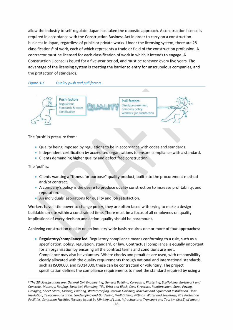
Figure 3-1 Quality push and pull factors
The ‘push’ is pressure from:
Quality being imposed by regulations to be in accordance with codes and standards.
Independent certification by accredited organisations to ensure compliance with a standard.
Clients demanding higher quality and defect free construction.
The ‘pull’ is:
Clients wanting a “fitness for purpose” quality product, built into the procurement method and/or contract.
A company’s policy is the desire to produce quality construction to increase profitability, and reputation.
An individuals’ aspirations for quality and job satisfaction.
Workers have little power to change policy, they are often faced with trying to make a design
buildable on site within a constrained time. There must be a focus of all employees on quality
implications of every decision and action: quality should be paramount.
Achieving construction quality on an industry-wide basis requires one or more of four approaches:
Regulatory/compliance led. Regulatory compliance means conforming to a rule, such as a specification, policy, regulation, standard, or law. Contractual compliance is equally important for an organisation by ensuring all the contract terms and conditions are met. Compliance may also be voluntary. Where checks and penalties are used, with responsibility clearly allocated with the quality requirements through national and international standards, such as ISO9000, and ISO14000, these can be contractual or voluntary. The project specification defines the compliance requirements to meet the standard required by using a
6 The 28 classifications are: General Civil Engineering, General Building, Carpentry, Plastering, Scaffolding, Earthwork and Concrete, Masonry, Roofing, Electrical, Plumbing, Tile, Brick and Block, Steel Structure, Reinforcement Steel, Paving, Dredging, Sheet Metal, Glazing, Painting, Waterproofing, Interior Finishing, Machine and Equipment Installation, Heat Insulation, Telecommunication, Landscaping and Gardening, Well Drilling, Fittings, Water and Sewerage, Fire Protection Facilities, Sanitation Facilities (Licence issued by Ministry of Land, Infrastructure, Transport and Tourism (MILT) of Japan).

19
quality management system. These are controlled in-house, or externally controlled and validated by specialists (clerk of works, independent consultant). Some governments have set up quality assurance agencies to help with compliance. For example, established in 1989 as a non-profit-distributing organisation by the Hong Kong Government, Hong Kong Quality Assurance Agency (HKQAA) helps industry and commerce in the development of quality, environmental, safety, hygiene, social and other management systems.
Market led. The companies decide on the establishment of their quality standard. BMW proved this worked in the automotive sector, where the product has a long term guarantee and is guaranteed for quality.
Industry-led registration schemes. Trade bodies establish minimum standards and requirements, members must comply with those standards to ensure membership of the body, such as Checkatrade, Corgi, and the Considerate Constructors’ Scheme.
Compensatory/insurance-led. Guarantees are offered, such as by the NHBC7, clients seek an external body to validate the quality guarantee.
Health and safety in UK construction has benefited greatly from the regulatory/compliance nature of
the CDM Regulations, with a legal requirement subject to punishment by fine/penalty. These clearly
set out the roles of the client, designer, and contractor in a project and their liabilities. The rail,
petrochemical, oil and gas, and energy industries are all very clear about what they need from a
quality system and what they are prepared to accept.
It is not just about getting paid to deliver good quality construction; quality should be a given right.
Clients wants projects to be quality assured. This defect prevention in quality assurance differs subtly
from defect detection and rejection in quality control.
3.5 Pressures
The construction site team face many pressures during the project from stakeholders, contractual
requirements, and to comply with regulations and legislation (Figure 3-2). They have to keep up with
the plethora of regulations, codes and standards, that are constantly being reviewed and updated,
and develop processes to deal with new construction technologies. Quality management across the
project is important for site safety, company reputation, and client satisfaction.
7 The NHBC (National House Building Council) provides warranties and guarantees for housing, registration scheme for contractors, and technical standards.

20
Figure 3-2 Pressures of rules, regulations, and legislation on the construction team
Keywords are: satisfying customers, delivering value, developing a culture of zero tolerance towards
poor workmanship, and being proud to exceed customer expectations.
A company's drive for quality management must involve the development of a planning mentality
that focuses on problem prevention. Preventive actions will reduce the overall cost of quality. Re-
work to remedy defects costs time, money, reputation, motivation, and leads to unhappy clients and
an unhappy workforce.
It is no use having the mentality that there is always time and money for re-work, but insufficient time
to do the job properly in the first place!
It is often easier to identify the cost of quality, where things may go wrong, the cost of re-work and
remedying defects. A cost-of-quality approach means a company can ascertain what resources could
be used to prevent poor quality, but that is a cost where nobody wins, getting it right first time saves
money, stress, and leads to satisfied customers.
There is no specific definition of construction quality. It is subjective and viewed from different
perspectives: the client, the design team, principal contractor, specialty contractors, end user,
companies in the supply chain, the workforce.
Construction is renowned for being a low profit margin industry. Poor quality is costing the industry
annually more than the combined profits of the large construction companies in the industry.
3.6 Balancing cost, time, and quality
There is always a balance between time, cost, and quality, with each taking on varying degrees of
importance across the project.
Quality is: profit to the maker, value to the user, and satisfaction to both.
Defective work, re-work, remedial work, and poor quality means everyone loses. It is estimated that
between 2%-5% of construction cost is spent on remedying defects and getting it right. In an
industry with wafer thin profit margins of 1%-3%, improving quality and customer satisfaction should
have high priority, alongside safety and health.

21
Identifying where, why and how failure occurs is important; either internal or external. The
associated costs may be the result of defects (during and post production), non-compliance to the
specification, standards and codes, poor information not communicated effectively, and the cost of
quality management to reduce/ eradicate failures.
Quality: a systematic approach to the search for excellence (synonyms: productivity, cost reduction,
schedule performance, sales, customer satisfaction, teamwork, the bottom line). ASQC
The client will use specification, standards requirements, codes of practice, and contract conditions
to stipulate a level of quality required on the project. The contract will state there is an absolute
obligation to carry out and complete the works “in a proper and workmanlike manner and in
compliance with the contract documents”. The contractor must perform the works where there is an
absolute obligation to carry out and complete the works with reasonable skill and care. Under
Section 14 of the Sale of Goods Act 1979, a term will be implied into a contract for the sale of goods
that the goods will be fit for purpose. There is an implied condition that the goods supplied under
the contract are reasonably fit for that purpose, whether or not that is a purpose for which such
goods are commonly supplied.
What the Sale of Goods Act 1979 says about implied terms for quality of fitness: (1) Except as provided by this section and subject to any other enactment, there is no
implied about the quality or fitness for any particular purpose of goods supplied under a contract of sale.
(2) Where the seller sells goods in the course of a business, there is an implied term that the goods supplied under the contract are of satisfactory quality.
(2A ) Goods are of satisfactory quality if they meet the standard that a reasonable person would regard as satisfactory, taking account of any description of the goods, the price (if relevant) and all the other relevant circumstances.
(2B) The quality of goods includes their state and condition and the following (among others) are in appropriate cases aspects of the quality of goods-
(a) fitness for all the purposes for which goods of the kind in question are commonly supplied
(b) appearance and finish (c) freedom from minor defects (d) safety (e) durability. (2C) The term implied by subsection (2) above does not extend to any matter making the
quality of goods unsatisfactory- (a) which is specifically drawn to the buyer’s attention before the contract is made (b) where the buyer examines the goods before the contract is made, which that
examination ought to reveal, or (c) in the case of a contract for sale by sample, which would have been apparent on a
reasonable examination of the sample.
‘Fitness for purpose’ warranties can be expressly agreed or implied in construction contracts or
consultancy agreements to ensure that, whatever is being designed, built or supplied is fit for its
intended purpose. A fit for purpose obligation in a construction contract simply means the contractor
agrees that the design will meet the employer's demands. Some contractors say, “I will not accept a
fitness for purpose obligation because it is too onerous and is not insurable”. The effect of including a
fitness for purpose clause in a construction contract can be very significant.

22
Design quality is about fitness for purpose, safety, buildability, and about service delivery, with the
right information provided at the right time for the job site, with no delays in approving and signing
off shop drawings. Design quality is also about completeness of design, with sufficient information
for the workforce to convert the design into production.
Quality management systems will be embedded by the contractor in the site delivery process. For a
smaller contractor they may not be formalised in manuals, but they will exist; such systems may be
not getting paid until they meet the required standard. Unless everyone on the project understands
the standards expected, the project can only be as good as the weakest link; there is no satisfaction
in the client saying the quality of the joinery on the project is wonderful, but they are experiencing
water leaks in the building!
Paying lip service to quality, ticking boxes, imposing unnecessary bureaucracy, and having
procedures that do not add value, does not lead to satisfied customers, or a satisfied workforce.
Specialist consultants with clip boards understand process, they need to fully understand production
on a construction project with everything in construction becoming more complex and
interdependent.
“It is no longer acceptable to think of quality as merely meeting the technical and performance
specifications in the contract….. that will lead to mediocrity.”
3.7 Quality actions
Quality actions can be classified into four main headings:
Prevention: activities that ensure right first time performance
Appraisal: activities that check whether right first time is achieved, not ticking a box, but really ensuring the quality requirements have been met from manufacture, delivery, storage, through to installation and testing on site.
Failure: activities which result from not conforming to right first time, which delay the project and cost everyone money.
Implications: in a litigious world there is a desire to hunt the guilty, if a piece of equipment fails the consequential loss can be significant and someone has to take responsibility. Insurers are not charities, they will only pay for gross neglect not poor quality.
Quality costs are both direct and indirect – the direct costs are getting it right first time and the cost
of remedial work, the indirect costs are loss of reputation and future work, as well as client and user
dissatisfaction.
Quality management procedures are much less expensive than litigation!
There is a plethora of quality-related codes and standards, the site team needs to be aware, and
understand the requirements and implications. These codes are important, but their format and the
language used is not conducive to quick reference by the site team on the project. They must be
purchased from British Standards and kept up-to-date. Chapter 11 of this Code outlines the codes
and standards in each work section, providing advantages, disadvantages, the related quality issues
as well as lists of codes and standards, both national and international.

23
4 Quality in practice
4.1 Learning from other industries about quality management
The construction industry must learn from other industries. It must discard the idea that it is
different to other industries; every industry sector has unique challenges. Yes, construction is a
bespoke industry, it cannot stock its products in a warehouse, nor have stocks of unsold goods. It
does not hold an annual sale where prices are reduced. It cannot rapidly generate work by having a
special sale. It has contractual liabilities with contracts that clearly allocate responsibility and
liability. It works on long time frames from concept through design and approvals, to site ready,
which can take years. It separates the design of its products, from the production process. The
payment system is slow and laborious. The quality control procedures are not central to everything it
does. Quality is seen as a matter of compliance, meeting standards and fitness for purpose. It is not
about exceeding customer expectations.
It all sounds familiar, but unlike an aero engine manufacturer, it is not reliant upon winning work by
exploiting advanced technology and then selling to the customers. It does not have long gestation
periods for research and development of new projects. It does not have to prove to the legislators
and approval agencies that its products are reliable and robust in every eventuality. Quality control,
quality assurance, and quality management is central to everything the aero manufacturer does, it is
at the core alongside safety, innovation, and exploiting technology. Quality is about exceeding
customer expectations by ensuring customers are happy.
Rolls Royce in the aero engine sector has 8 QM principles:
1. Customer focus
2. Leadership
3. Involvement of people
4. Process approach
5. Systems approach to management
6. Continual improvement
7. Factual approach to decision making
8. Mutually beneficial supplier relationships
This would be a very different list in construction companies with 6 QM principles;
1 Leadership and engendering a culture of QM
2. Process approach
3. Ensuring the supply chain is fully aware of the quality standards expected and delivered
4. Mutually beneficial supplier relationships
5. Systems approach to management
6. Factual approach to decision making
7. Customer focus
It is unlikely that continuous improvement would be present in construction, with the argument that
the industry builds one-off unique projects, which are built by temporary project teams assembled

24
to deliver a project. Mutually beneficial supplier relationships exist with framework agreements, but
trust and loyalty are lacking, mainly because the industry is focused upon lowest cost, rather than
value for money, and the way the project design is rarely complete at the start of a project.
A leap into the future is required by the construction industry to satisfy its clients and itself that
quality is a top priority.
4.2 Learning from overseas
The Construction Quality Assessment System (CONQUAS), was introduced in Singapore in 1989, it
serves as a standard assessment system on the quality of building projects. A de facto national
yardstick for the industry, CONQUAS has been periodically fine-tuned to keep pace with changes in
technology and quality demands of a more sophisticated population. In 1998, BCA introduced a
number of new features to CONQUAS resulting in the launch of CONQUAS 21. The latest CONQUAS
9th edition was launched in 2016 to promote the adoption of DfMA which supports both high quality
and productivity, and to ensure the score commensurate with end users expectation on
workmanship quality.
The building is assessed based primarily on workmanship standards through site inspection. Each
component is divided into different items for assessment. The sum of the 3 components gives the
CONQUAS score for the project. By using CONQUAS as a standardized method of quality assessment,
developers are able to use the CONQUAS score to set targets for contractors to achieve and also
assess the quality of the finished building.
4.3 Defining quality – an industry view
4.3.1 Building in Quality
The ‘Building in Quality’ report, a collaboration between the RIBA, CIOB and RICS, established three
dimensions of quality:
Build quality – completed asset performance
Functionality – fitness for purpose
Impact – the degree to which the asset adds social, economic, cultural and environmental value and improves wellbeing.
A number of gaps were identified in the pursuance of quality in the industry:
Lack of an agreed definition
Need for better prediction of the asset’s final quality
Available methods of measurement, monitoring etc.
Data against which benchmarking can be undertaken
Risk control and handling uncertainty.
To address these gaps, a digital system for monitoring the risks to quality – the Quality Tracker is
proposed. “The Quality Tracker is at the heart of a chain of custody system for overcoming the often
fragmented composition of project teams and the resultant inconsistent governance of quality”
(Building in Quality, page 25). The process is important in identifying quality issues for the client, but
it needs to be agreed by the project team and, importantly, recorded and signed off impartially at
pre-agreed stages. “The quality baton is passed on until finally issued to the client’s representative,
the investors, the purchasers and/or tenants as a verified statement of the ways in which risks to

25
quality were handled during the project”. At each work stage, risk assessments may be interpreted
in the context of the quality targets set out in the project brief. Each ‘page’ of the Tracker covers one
of the stages in the RIBA Plan of Work. The construction/production phase is Stage 5 of seven stages.
Comment: Site-based quality management is a very broad and multi-faceted area, involving the supply
chain and a complex team of stakeholders across the value chain. The Quality Code addresses the
need to focus on the detail of the production process and what is required from the
project/construction/site manager. It can be an important part of a quality management toolbox
alongside the Quality Tracker.
4.3.2 The Hackitt Report
The Hackitt report is an “Independent Review of Building Regulations and Fire Safety”. The report
stated that there was “insufficient focus on delivering the best quality building possible, in order to
ensure that residents are safe, and feel safe”. The report identified a need for a new regulatory
framework that would provide both positive incentives and effective deterrents to ensure
competence levels are raised and quality and performance of construction products improved.
The report states that a more effective testing regime is needed and innovative product and system
design with efficient quality controls, should be sought. Effective and accurate information
management was seen as crucial, not just across the project but over the life of a facility, to improve
quality and performance – the ‘golden thread of information’.
4.3.3 Get it Right Initiative8
The initiative has 4 objectives:
To generate a significant change in the efficiency of the UK construction industry through reducing the amount of errors made in construction.
To undertake research to identify, evaluate and prioritise the principal systemic errors in the construction process.
To develop a strategy to address these errors and in particular to address deficiencies in skills.
To develop new training products and processes to address the skills deficiencies.
Industry opinions were sought on the issue of ‘getting it right, first time.’ It identified the sources of
most frequent errors, root causes of error, cost of error, and how to avoid making errors.
The Strategy for Change outlines: a skills development programme; a campaign to change and align
attitudes across the sector so that “all involved are committed to reducing errors and improving the
quality of what we do”, and; improvements needed in management processes and systems,
particularly design management and construction planning.
Comment: This initiative focuses on education, skills and attitudes, backed up by data on types of
errors, their costs and frequencies. The Quality Code shares those concerns about skills deficiencies as
this would impact best practice and the effective use of a quality management plan.
Three reports complement the CIOB Quality Code. To achieve change will require commitment, and
action, across all parts of the project and amongst the stakeholders/decision makers involved.
8 The Get it Right Initiative is an organisation that is tackling avoidable error in the construction industry. Membership is by subscription. Get It Right Members work together to steer the agenda and build a better UK Construction industry.

26
4.4 Practitioners’ views
The Call for Evidence issued by the CIOB, prompted important and valuable insights into the
management and state of quality in the construction sector. Members were asked a series of
questions; the feedback can be divided into the 5 main actors/areas in construction that impact
quality:
Clients
Designers
Company
Workforce
Governance
Based on the number of times an actor was mentioned, the company and the workforce came out
on top. Clients and designers were referred to in equal measure and governance mentioned the
least – see Figure 4-1.
Figure 4-1 Frequency of the players mentioned in the replies
The words “experience” and “training” were widely used as being an issue in the delivery of quality.
On-the-job training was considered essential by many respondents, who emphasised the need for
the training to be consistent and relevant. The inclusion of quality in a curriculum, either at a
university/college, or on site, is seen as important. Views on the responsibility for training were
mixed. Some saw the government as responsible, others saw either the companies or construction
organisations, such as the CITB, needing to take greater accountability. There was a perceived lack of
specialist/professional skills. Management and leadership skills were highlighted as being essential,
but often seen as lacking.
“NVQs are no substitute for experience, skill and knowledge.”
Questions asked whether or not the current management of quality is adequate in three areas -
supervision, sign-off, workmanship.
It is hard to find anyone who is against quality.
4.4.1 Supervision
Site supervision is seen as the key factor in QM. Lack of quality checks is seen as both a contractor
and client responsibility. Respondents remarked on the inadequate supervision at the construction
stage provided by design team architects and engineers. This criticism may be unfair, it fails to
Client/Procurement…
Designer10%
Contractor37%
Workforce37%
Governance7%
27
recognise the contractual liability issues of the design team, the reduction in the level of fees paid
for professional services, and the consultant’s obligation to use skill and care normally used by
professionals. The consultant is not liable for a defect unless they fail to carry out skill and care in
their professional duty. The consultants’ role is check compliance once the scope requirements have
been specified. Design and build is different where the contractor carries responsibility for both
design and site production.
The demise of the independent Clerk of Works9 position was seen as a retrograde step. The
reduction in staff numbers on site puts pressure the ability to provide adequate supervision. Fees for
independent inspections are an additional cost that will pay benefits in the long run by saving money
on the cost of re-work, and the cost of defective workmanship. Identifying faults early will save time
and money.
4.4.2 Sign-off/taking over the works/practical completion
Most respondents felt that the sign-off process at the end of the project was inadequate. A lack of
assigned responsibility was cited as a reason; Inspection and Test Plans (ITPs) were suggested as one
solution. There was concern about the clarity of the sign-off process, in particular, the
documentation involved, e.g. Building Control Completion Certificate or a Practical Completion
Certificate, which are not proof of quality. As-built information is often not sufficient to reflect the
changes made during the site production stage.
“The sign off stage needs to be quality focused and not merely getting payment
and let’s hand this over.”
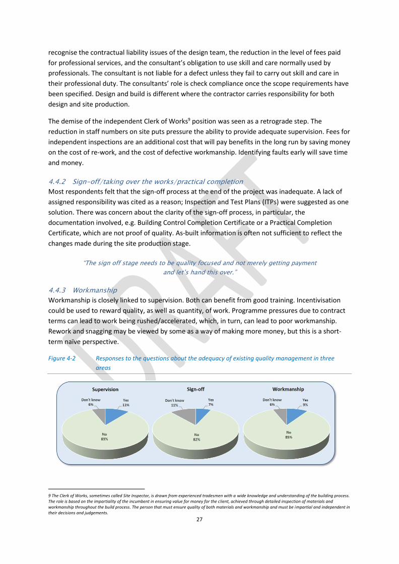
4.4.3 Workmanship
Workmanship is closely linked to supervision. Both can benefit from good training. Incentivisation
could be used to reward quality, as well as quantity, of work. Programme pressures due to contract
terms can lead to work being rushed/accelerated, which, in turn, can lead to poor workmanship.
Rework and snagging may be viewed by some as a way of making more money, but this is a short-
term naïve perspective.
Figure 4-2 Responses to the questions about the adequacy of existing quality management in three
areas
9 The Clerk of Works, sometimes called Site Inspector, is drawn from experienced tradesmen with a wide knowledge and understanding of the building process. The role is based on the impartiality of the incumbent in ensuring value for money for the client, achieved through detailed inspection of materials and workmanship throughout the build process. The person that must ensure quality of both materials and workmanship and must be impartial and independent in their decisions and judgements.

28
Figure 4-2 shows the responses from the three questions. Whilst training, incentivisation and
supervision can make a difference to quality, placing a greater emphasis on individuals to produce
good workmanship is a more sustainable approach, with long-term benefits for both the company
and the individual.

29
5 The drivers, issues, disruptors and enablers of
construction quality management
5.1 Background
The CIOB Call for Evidence and the research identified a number of major drivers that impact
construction quality. These are the BIG 11 drivers:
Good design, which means design that is well engineered, buildable, with sufficient detail to ensure the contractor and specialty contractors do not have excessive requests for information and clarification, with a design that is sufficiently complete at the project award stage to allow a start on site. Lack of information means everyone suffers.
Realistic project programming from the outset of the project, with allocated float time.
Climate and the impact of weather on materials, manpower and process. Over optimistic assumptions about eh weather lead to delays and poor quality.
Timely and relevant data and information provided by the design team and by the principal contractor to the supply chain.
Site management and production, with a production team that has the appropriate competencies for the project.
People and performance by motivating the workforce, training the workforce, and respecting the work of others.
Clients recognising the impact of design changes once production has commenced on site.
Governance and over burdensome regulations and procedures add little and take unnecessary time. Procedures do not ensure top quality, it is the people.
Corporate behaviour demonstrating leadership from the top about the importance of quality.
Realistic budgeting at the outset, taking account of risk and uncertainty, and building in contingencies to take account of the unexpected. Avoiding the blame culture and focusing on commitment to quality.
Materials – procurement, storage and handling, with clear information about the requirements to ensure the materials and components meet their design specification.
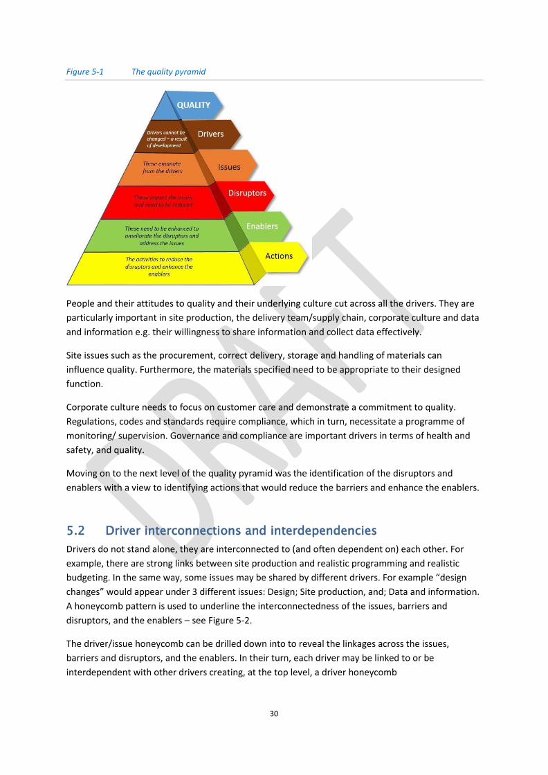
They come at the top of a ‘quality pyramid’ (Figure 5-1) that presents a hierarchical system of
drivers, issues, disruptors, enablers and actions. Whilst the list above provides the major drivers,
identifying the issues that come from the drivers, disruptors, enablers and actions required more
detailed drivers that relate better to construction projects.
For example, realistic programming and budget are key to the success of a project and will heavily
impact quality. As one respondent commented in the Call for Evidence (CfE):
“Design is about buildability and appropriate specifications as well as the importance of being close to
100% complete before production begins.”
Timely information means there is not the last minute rush because the information was not
available when the work package starting. Everyone will change their minds, but there has to be
recognition that late changes are de-motivating for the workforce and can slow the project, putting
pressure on the workforce to deliver top quality in an unrealistic time frame.
30
Figure 5-1 The quality pyramid
People and their attitudes to quality and their underlying culture cut across all the drivers. They are
particularly important in site production, the delivery team/supply chain, corporate culture and data
and information e.g. their willingness to share information and collect data effectively.
Site issues such as the procurement, correct delivery, storage and handling of materials can
influence quality. Furthermore, the materials specified need to be appropriate to their designed
function.
Corporate culture needs to focus on customer care and demonstrate a commitment to quality.
Regulations, codes and standards require compliance, which in turn, necessitate a programme of
monitoring/ supervision. Governance and compliance are important drivers in terms of health and
safety, and quality.
Moving on to the next level of the quality pyramid was the identification of the disruptors and
enablers with a view to identifying actions that would reduce the barriers and enhance the enablers.
5.2 Driver interconnections and interdependencies
Drivers do not stand alone, they are interconnected to (and often dependent on) each other. For
example, there are strong links between site production and realistic programming and realistic
budgeting. In the same way, some issues may be shared by different drivers. For example “design
changes” would appear under 3 different issues: Design; Site production, and; Data and information.
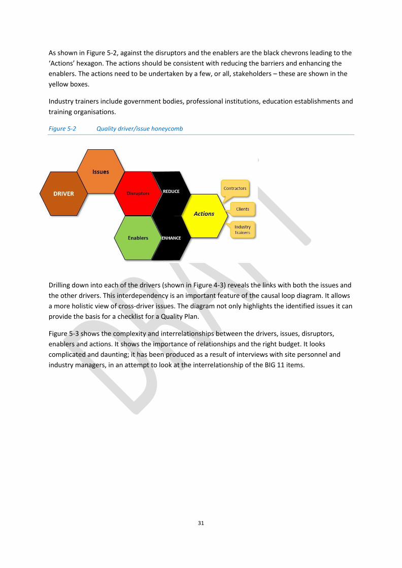
A honeycomb pattern is used to underline the interconnectedness of the issues, barriers and
disruptors, and the enablers – see Figure 5-2.
The driver/issue honeycomb can be drilled down into to reveal the linkages across the issues,
barriers and disruptors, and the enablers. In their turn, each driver may be linked to or be
interdependent with other drivers creating, at the top level, a driver honeycomb
31
As shown in Figure 5-2, against the disruptors and the enablers are the black chevrons leading to the
‘Actions’ hexagon. The actions should be consistent with reducing the barriers and enhancing the
enablers. The actions need to be undertaken by a few, or all, stakeholders – these are shown in the
yellow boxes.
Industry trainers include government bodies, professional institutions, education establishments and
training organisations.
Figure 5-2 Quality driver/issue honeycomb
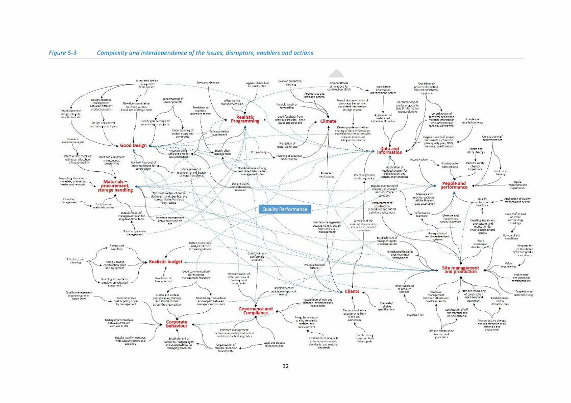
Drilling down into each of the drivers (shown in Figure 4-3) reveals the links with both the issues and
the other drivers. This interdependency is an important feature of the causal loop diagram. It allows
a more holistic view of cross-driver issues. The diagram not only highlights the identified issues it can
provide the basis for a checklist for a Quality Plan.
Figure 5-3 shows the complexity and interrelationships between the drivers, issues, disruptors,
enablers and actions. It shows the importance of relationships and the right budget. It looks
complicated and daunting; it has been produced as a result of interviews with site personnel and
industry managers, in an attempt to look at the interrelationship of the BIG 11 items.
32
Figure 5-3 Complexity and interdependence of the issues, disruptors, enablers and actions

33
5.3 Site-based procedures
On medium to large projects, site management relies upon a team of people, working together to
supervise and manage site-based staff to ensure the project is delivered to specification, required
standards, and within the terms of the contract. On small projects, there may be just one site
manager who may also be the contractor. Whatever the size of the project, the aim is the same; it is
about planning and co-ordination of all the production processes to deliver a project that is on time,
on budget, and of the required quality.
Quality is equally important on small projects, clients are sometimes unclear what they want at the
outset of the project, they think tit can designed and changed as the project proceeds, that is where
confusion arises. Any change of mind will have consequences on the programme, the cost, and the
quality of the work.
Site-based procedures have a huge bearing on quality. They are impacted by the level of skills
available, as well as time and cost. Quality depends upon good design and suitable specifications,
and upon buildability and how materials, components and systems are assembled and constructed
in a way that is safe and fit for purpose. Sometimes the problems are made bigger when there are
multiple layers of specialty contractors/sub-contractors. Often the organisation at the bottom of the
chain becomes remote from those at the top, pressure is placed on cost and time to deliver the
task/work package to ensure other packages are not delayed. Pressure manifests itself in stress for
the workforce, with the target to deliver on time irrespective of the consequences. Time becomes a
cost pressure, and time becomes the biggest enemy of quality management because of the need to
deliver to the agreed target.
Planning to deliver good quality should be considered alongside risk, and health and safety. They are
underlying issues across the whole production process and need careful consideration. If planning is
to add value then it should look at costs and benefits e.g. good quality production and the avoidance
of costs due to unplanned activities. Planning allows alternatives to be considered and evaluated and
can lead to being proactive rather than reactive. Planning a construction project is about ensuring
the effective use of resources (people, plant and equipment) as well as space, information, time and
money to deliver on time, on budget and at the required quality.
How does a company know if their quality initiatives are the right ones? There will always be new
approaches and new software claiming to improve the quality management process. Quality
Planning is a process that quality departments, quality managers, and quality professionals
undertake in their organizations to identify the quality initiatives to best manage quality today and
on into the future. Get started, by creating a team of quality enthusiasts responsible for ensuring the
delivery of quality products and services to the customers. The site team are key to delivering quality
on the job site.
A refurbishment project of an occupied building will present challenges of ensuring all the
stakeholders are happy, it will not be just the quality of the workmanship and materials that
matters. Disruption to the daily life of the tenants will be their perception of quality. They will
remember the driven piles with the noise and vibration, whereas an alternative may have alleviated
the problem.

34
The production plan should include inspection procedures, testing, and their regularity, with a
contingency should remedial work be necessary. Quality assurance protocols need to be established.
A project quality plan may be used to identify quality requirements, the roles and responsibilities,
and the resources required to ensure adherence to the plan. The plan should detail the procedures
for dealing with defects and the document control procedures.
5.4 Temporary works
Temporary works, although temporary and necessary,
can constitute a significant part of the project cost.
Their design, execution and management are
important for engineering, quality, safety and
efficiency. The design of temporary works should
follow a design brief and involve independent checking
of the temporary works design. Their
erection/installation must be regularly inspected to
ensure compliance with temporary works legislation,
e.g. formwork, falsework, shoring etc.
5.5 Off-site manufacturing
Whilst off-site manufactured components/modules may go through stringent factory quality
controls, once they get to the site they need careful supervision to ensure continuing quality. This
type of product is often large scale e.g. bathroom pods and requires specialist transport and
handling as well as the space and expertise to put them into place. Thus, on projects involving a high
degree of pre-assembly, the role of experienced site management staff becomes more important.
Site workers become assemblers rather than traditional builders.
By their very nature, off-site systems are standardised, taking full advantage of ‘production line’
techniques. Thus, they may not be compatible with highly engineered or complex architectural
designs. The integration of the system into the existing framework on site is crucial to ensure
weather tightness, durability and achieving fit for purpose. It requires skills and relies upon regular
inspections to ensure good quality.
5.6 Materials quality
Materials include manufactured products such as components, fittings, items of equipment and
systems; naturally occurring materials such as stone, timber and thatch; and backfilling for
excavations in connection with building work.
Approved Document 7: Materials and workmanship, Building Regulations 2010

35
To ensure quality on delivery, materials should be checked for the right quantity and the right
quality. Materials handling and storage will impact quality. Materials packaging is to protect the
goods in transit; the suppliers aim is to ensure
materials and components are delivered in perfect
condition. Once on site, the materials become the
responsibility of the contractors and before
installation the materials are vulnerable to damage
in handling and installation. Expensive materials
need respect. Damaged materials cost money,
nobody is happy if the material is damaged after
installation and before handover. An inventory
helps to track the type, quantity, quality, and
placement of materials on site as well as the control
of site materials information (e.g. existing materials on site, existing stock, and despatched
materials).
Both internal and external controls can be carried out. For example, the control of concrete received
by the contractor can be carried out by an independent entity; the execution of steelworks can be
controlled by the project manager (on behalf of the client), or the construction company can
establish an internal control for the execution of the building work.
5.6.1 Certification of materials, components and systems
Specifications describe the materials and workmanship required for a project. The specification must
be read with other information such as quantities, schedules and drawings. The specifications should
include certified materials/ components/systems in order to satisfy performance requirements.
Performance specifications are written on projects that are straight-forward and are well-known
building types; whereas prescriptive specifications are written for more complex buildings, or
buildings where the client has requirements that might not be familiar to suppliers and where
certainty regarding the exact nature of the completed development is more important to the client.
Table 5-1 shows a range of certification schemes covering construction materials and components.
Table 5-1 A selection of certification schemes covering construction materials etc.
From 2014, the CE (Communauté Européenne) marking of structural steelwork and aluminium was made mandatory. CE is a “declaration of performance” not a quality mark. It covers 400 products including: Timber; Wood flooring, wood panelling, cladding; Concrete, wall elements, Beam: precast blocks; Glass blocks and pavers
The Kitemark, which indicates that a product has been independently tested by BSI (the British Standards Institute) to confirm that it complies with the relevant British Standard, and have licensed the product manufacturer to use the Kitemark.
FSC stands for 'Forest Stewardship Council' - an international non-profit organisation dedicated to promoting responsible forestry. FSC certifies forests all over the world to ensure they meet the highest environmental and social standards.
The British Board of Agrément (BBA) is a construction industry approvals body, that was set up in 1966 by the UK government offering product and installer approval. Agrément certificates cover 200 different product sectors; the largest of these are insulation and roofing. The BBA runs an insulation Approved Installer Scheme, linking installations of injected cavity wall insulation to BBA approval and dealing with both the system supplier and installer. BBA approvals show compliance with Building Regulations and other requirements, including installation quality. The BBA also inspects for the Fenestration Self-Assessment Scheme (FENSA) and the Federation of Master Builders. The BBA runs the Highways Authorities Product Approval Scheme (HAPAS), County Surveyors Society and other UK agencies.
36
The United Kingdom Accreditation Service (UKAS) is the sole national accreditation body for the United Kingdom. UKAS is recognised by government, to assess against internationally agreed standards, organisations that provide certification, testing, inspection and calibration services. UKAS provides accredited testing, calibration, inspection and certification to give consumers, suppliers, purchasers and specifiers the assurance that construction projects run efficiently, construction sites are safe and reliable materials are used. They also provide Government and Regulators with reliable evidence that completed projects meet regulatory compliance.
BRE Global, a UKAS accredited certification body, provides independent, third-party certification of fire, security and environmental products and services.
5.7 Governance and compliance
Governance and compliance affect quality management and can entail costs – some very significant
e.g. claims for the collapse or weakening of a structure.
Corporate governance can be seen to entail the relationships between a company’s management, its
board, its shareholders, and other stakeholders and to provide the structure through which the
objectives of the company are set, and the means of attaining those objectives and monitoring
performance are determined (OECD, 2004)
Governance is the set of rules by which a company operates. The rules fall into two categories, those
dictated by legislation, codes and standards, the other are the corporate ‘rules’. The latter cover the
infrastructure and processes that the company put in place under
which the projects function in order to ensure compliance.
The need for compliance with regulations, standards and codes that
govern construction as well as registration and certification
requirements are the ‘push’ factors in the drive to achieve quality see
Figure 3-1.
Compliance is increasingly important, companies are faced with a
growing amount of regulation and legislation with the need to
document and report many of the activities on site. Off site, financial
regulations and corporate social responsibility (CSR) legislation are the
responsibility of the ‘head office’, or, in the case of an SME, would
probably be dealt with by the main contractor.
The contractor has an obligation to ensure that work on the project complies with the relevant
legislation. This necessitates communication with local authority officers (e.g. building control),
Factory Inspector, Health and Safety inspectors, and any other officials that need to check/supervise
the way the work is being carried out. Inspectors may also need access to the site to check on work
done by speciality contractors. Site inspections might include:
Planning inspections to verify compliance with planning permissions, conditions and obligations
Inspections by representatives of funding bodies to review progress and quality for the release of money
Inspections by insurers to ensure compliance with their terms and conditions
Highways Authority inspection of roads and sewers to review any damage to roads and crossovers

37
Health and Safety Executive inspections for compliance with health and safety standards
Building control officer or approved inspector inspections during the progress of the work
Environmental Health Officer - inspections related to pollution (mud, noise, smoke and water) and certain installations, such as drainage and kitchens
Fire Officer - inspection of fire escapes, and for hazards e.g. storage of certain materials
Tree Preservation officer - inspection of protected trees
Archaeological inspection of excavations, where the site is an archaeological area
Factory inspectorate inspections
5.8 Certification, verification, and accreditation for quality
management
Certification, verification, and accreditation is part of the independent process to ensure there are
checks in the system. Accreditation is the formal tool to provide a high degree of assurance that the
organisations implementing these processes (activities or tasks) are competent. Outcomes and
actual performance by accredited organisations over time are important to maintain
accreditation. Quality management systems can be checked by accredited checkers. Samples,
products, services, or management systems can be evaluated against specified requirements by
laboratories, certification bodies, and inspection bodies. Accreditation is the independent evaluation
of these conformity assessment bodies against recognised standards to carry out specific activities to
ensure their integrity, impartiality, and competence. Accreditation provides the assurance for the
client to rely on commercial providers of evaluation and inspection services.
The United Kingdom Accreditation Service (UKAS) is the sole national accreditation body for the
United Kingdom. UKAS is recognised by government, to assess against internationally agreed
standards, organisations that provide certification, testing, inspection and calibration services.
Accreditation by UKAS demonstrates the competence, impartiality and performance capability of
these evaluators. In short, UKAS ‘checks the checkers’.
Accreditation is the formal recognition that an organisation is competent to perform specific
processes, activities, or tasks (which are detailed in a scope of accreditation) in a reliable credible
and accurate manner. Accreditation delivers confidence in certificates and conformity statements. It
underpins the quality of results by ensuring their traceability, comparability, validity and
commutability.
Surveillance visits from the certification body aim to find out whether a QMS really works in
everyday operations, or not. It will focus on whether all corrective and preventive actions are
properly recorded and implemented, whether the top management really supports and cares about
the QMS.
Verification, testing and certification by an independent accredited body for quality assurance and
control can be part of the contract conditions, with the client wanting independent checks to ensure
quality is maintained.
38
5.9 Procurement
There are different types of procurement for construction projects, each one encompasses different
levels of risk ownership for the project stakeholders. The five main methods of procurement are:
Traditional/conventional, where design is separated from construction
Design and build
Management procurement, such as construction management and management contracting where design and production can proceed in parallel
Integrated, sometimes known as collaborative procurement, partnering, alliancing, where the focus is upon collaboration and working together
Concession agreements, such as build/operate/transfer (BOT), public-private partnerships, private finance initiatives, where a team is formed for project delivery over a concession period award by the sponsor.
Risk ownership is an important consideration in quality-related activities as failure and non-
conformance risks are related to poor quality management. Quality requirements can be a pre-
requisite for the selection criteria at the tender stage. Evidence is required that the contractor has a
quality management system in place that will also be applicable to the supply chain.
A contract is awarded on the basis of either:
Lowest price: The lowest priced tender wins. No other element of the tender may be taken into
account.
Or
Most economically advantageous tender (MEAT): Factors other than, or in addition to price, like
quality, technical merit, and running costs can be taken into account. In MEAT, the contract
award criteria, e.g. price, quality of services, risk to contracting authority, and any sub-criteria
must be set out either in the tender documents; and the weighting of each criterion, and sub-
criterion if weighted, must also normally be given, either as an exact number or as a meaningful
range (e.g. price: 30%-40%).
Approved lists and framework agreements can help the client to be more confident about the
quality credentials of possible bidders.
5.10 Data and information
5.10.1 Project document management
ISO 9000 sets out a document control procedure system for quality management. It classifies project
documents in a 3-tier system:
Level 1: The top level of the quality documentation includes all documents describing the project. These include quality policy (short, concise statements of the project's guiding principles), general responsibilities, general administrative rules, references to quality procedures.
Level 2: Procedures provide organisational know-how. They briefly show inputs, outputs, activities and responsibilities for each business process. Process is a system of activities which uses resources to transform inputs into outputs. Procedures document the specific realization of a process in a project. They are very useful for analysing the existing project, identifying overlaps and gaps and confused responsibilities.
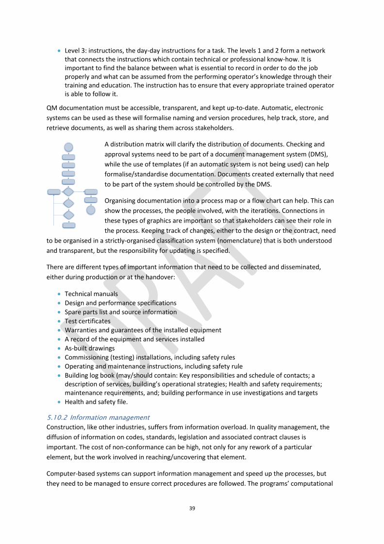
39
Level 3: instructions, the day-day instructions for a task. The levels 1 and 2 form a network that connects the instructions which contain technical or professional know-how. It is important to find the balance between what is essential to record in order to do the job properly and what can be assumed from the performing operator’s knowledge through their training and education. The instruction has to ensure that every appropriate trained operator is able to follow it.
QM documentation must be accessible, transparent, and kept up-to-date. Automatic, electronic
systems can be used as these will formalise naming and version procedures, help track, store, and
retrieve documents, as well as sharing them across stakeholders.
A distribution matrix will clarify the distribution of documents. Checking and
approval systems need to be part of a document management system (DMS),
while the use of templates (if an automatic system is not being used) can help
formalise/standardise documentation. Documents created externally that need
to be part of the system should be controlled by the DMS.
Organising documentation into a process map or a flow chart can help. This can
show the processes, the people involved, with the iterations. Connections in
these types of graphics are important so that stakeholders can see their role in
the process. Keeping track of changes, either to the design or the contract, need
to be organised in a strictly-organised classification system (nomenclature) that is both understood
and transparent, but the responsibility for updating is specified.
There are different types of important information that need to be collected and disseminated,
either during production or at the handover:
Technical manuals
Design and performance specifications
Spare parts list and source information
Test certificates
Warranties and guarantees of the installed equipment
A record of the equipment and services installed
As-built drawings
Commissioning (testing) installations, including safety rules
Operating and maintenance instructions, including safety rule
Building log book (may/should contain: Key responsibilities and schedule of contacts; a description of services, building’s operational strategies; Health and safety requirements; maintenance requirements, and; building performance in use investigations and targets
Health and safety file.
5.10.2 Information management
Construction, like other industries, suffers from information overload. In quality management, the
diffusion of information on codes, standards, legislation and associated contract clauses is
important. The cost of non-conformance can be high, not only for any rework of a particular
element, but the work involved in reaching/uncovering that element.
Computer-based systems can support information management and speed up the processes, but
they need to be managed to ensure correct procedures are followed. The programs’ computational

40
speeds can relieve pressure on the project team and cope with the large amounts of data that may
be produced/collected in a single project. Information needs to be stored in such a way that it is
secure but accessible, especially to teams on future projects – lessons learned about say, quality
failures or non-conformance examples need to be readily available.
Whilst information and communication technologies (ICT) play an important role in construction
quality management, the effectiveness of face-to-face meetings and physical system/component
checks should not be forgotten. However, these ‘human’ approaches can be well supported by auto-
ID systems such as bar codes RFID tags and so on. As much information as possible is needed about
the quality required, how to achieve it and how to manage it. Innovations into embedding
information into materials, components and the drawings themselves are already available, but the
cost of collecting the data to ‘service’ these systems can often be too high for small and medium
enterprises.

41
SECTION TWO

42
6 The importance of the quality management plan (QMP)
Quality management involves planning, doing, checking, and acting to improve project quality
standards.
It can be broken down into three process groups:
Quality Management Planning (QMP)
Quality Assurance (QA)
Quality Control (QC)
Quality management planning requires the identification of the quality standards relevant to the
project and how to satisfy them. It involves identifying and defining appropriate quality metrics and
measures for standards for project processes, product functionality, regulatory compliance
requirements, project deliverables, project management performance, documentation, testing, etc.
This should include the acceptance criteria for project deliverables and product performance.
The simple breakdown should be: This is what we want for the quality requirements on the project, defined in
sufficient detail and clarity as possible. This is how we will plan and deliver the quality required, with the acceptance
criteria. These are the checks and balances we will perform to ensure the quality is
maintained to the required standard in a consistent way, with the audit and recording process.
These are the tests and validation processes we will undertake validated by an accredited body.
This is how we will hand over the project following inspection and any snagging.
Project quality must be clearly defined at the outset – the standards and expectations of the client
and to identify critical success factors, and metrics for which to measure success. Defining project
quality is more that defining compliance with certain standards. If there are parts of the project
where special attention will be needed, these must be clearly defined for the construction team.
Hiding behind a Code or Standard, without clear definition of what is required on the project will not
satisfy anyone.
The QMP should outline acceptance criteria for project deliverables and product performance and
identify methods of data collection and archiving, and document timeframe for measurement and
metrics reporting.
A QMP is part of a project quality system, which comprises information on project personnel,
requirement and plan for inspections and tests, and how quality management will be audited,
reported, and recorded – see Figure 6-1 Effective quality planning.

43
Figure 6-1 Effective quality planning
The QMP is created as early as possible during the planning phase of the project. The audience is the
project manager, site manager, project team, design team, client, and any people whose support is
needed to carry out the plan.
The QMP documents the information required to manage effectively project quality from project
planning to delivery. It defines a project’s quality policies, procedures, criteria for and areas of
application, and roles, responsibilities and authorities. Its author(s) and the approval processes
required should be clearly stated.
The QMP should describe the primary roles and responsibilities of the project staff as it relates to
the practice of project quality management. It should also indicate responsibilities for activities such
as mentoring or coaching, auditing work products, auditing processes, participating in project
reviews, etc. The tools required to measure project quality and the level of conformance should be
included. For example, if benchmarking is to be used, this needs to be noted with the relevant
industry benchmark/standard.
The QMP should:
Describe how quality requirements will cascade down and through the supply chain and how quality assurance and quality control will be maintained on the project.
Define the individuals responsible for implementing the plan with their contact details.
Describe the key activities necessary to deliver the project quality and the order in which they will be carried out.
Describe the resources that must be provided, including the requirement for pictures, diagrams and text to be provided.
Describe procedures for dealing with and remedying defects if they occur.
Describe change control procedures when changes are made to the design/specification to ensure everyone in the site team is fully aware of the requirements.
Set out any special training requirements to ensure quality is maintained.
Schedule tools that will be used for quality control.
List relevant reference material.
Describe any special characteristics relating to quality in the contract terms and conditions for the project.

44
7 Producing a quality management plan (QMP)
7.1 Introduction
Build quality is about ensuring performance and compliance. It is about ensuring the asset functions
as designed and in accordance with what the client wants. It is about the impact of the quality on
the environment, and the value for the client. If something fails there can be serious consequences,
with physical danger, financial loss, and reputational loss. Safety and health on the job site is an
important part of build quality, sloppy untidy sites can lead to accidents.
7.1.1 The choice
The construction industry has a choice, improve quality standards by making a concerted effort, by
collaborating, and by accepting responsibility, or the public sector and private clients will impose
quality standards on the industry. The current situation is not sustainable.
7.2 Quality objectives
Quality objectives need to be set as part of any QMP. These are to:
Be consistent with the quality policy of the organisation by being objective and providing an evidence-based view of performance on a project.
Not tolerate continued poor performance.
Be measurable.
Take into account applicable requirements in the specification and the contract terms and ensuring the client and design team are made aware of the technical challenges.
Ensure the requirements of the products and services of manufactured goods are met.
Monitor the quality standards being achieved on the project.
Communicate effectively, openly and honestly.
Keep up to date with changes in legislation on quality.
In order to achieve these objectives, an organisation needs to decide what will be done, what
resources are needed to do it, who will be responsible, when they will be completed, and how the
results should be evaluated/measured.
7.3 Quality management (QM)
QM should be capable of being third party certificated to an international standard. QM includes
planning, control, assurance, and improvement of outputs. The challenge in construction is the
diversity of organisations in the supply chain and their interdependence to produce a final project.
Small, medium and large projects all have the same characteristics with long supply chains and
organisations being dependent on each other to meet the project requirements. Ultimately, it is
about responsibility, and a willingness to deliver the best quality possible.
Control of the contractor’s own activities is required, and control through the supply chain needs to
be managed. To ensure quality assurance can be maintained there is a requirement that the design
team provides timely information about the design requirements.

45
7.3.1 Site induction - training and education
Site induction is an important requirement for quality-related training and education. In the same
way that safety induction is delivered, the company’s quality objectives should be explained and
attention drawn to the quality management plan with the supervisory, monitoring and testing
processes.
7.4 Difference between quality assurance and quality control
Quality assurance and quality control are integral parts of quality management. Quality assurance is
the process of managing for quality; quality control is used to verify the quality of output.
Whilst quality assurance is the responsibility of everyone involved in a project, quality control is
usually the responsibility of a specific team/person. The aim of quality assurance is to improve
processes and development in order to prevent defects; quality control’s goal is to identify and
correct defects as soon as possible.
Quality assurance is a management tool and is process oriented
Quality control is a corrective tool and is product oriented.
7.5 Quality control
7.5.1 Quality testing
Apart from regular testing and inspections, the on-site inspections that require the presence of a
specialty contractor (or designated third party) are electromechanical systems, conveying systems,
and electrically operated equipment, which are operate after connection to a permanent power
supply. These include:
HVAC system Firefighting system
Water supply, plumbing, and public health system
Integrated automation system (building automation system)
Telephone system Communication system
Public address system Conveying system
Fire alarm system Electronic security and access control system
Electrical lighting and power system
Grounding (earthing) and lightning protection system
Emergency power supply system
Electrically operated equipment
7.5.2 Quality inspection
The aim of an inspection is ensure that the material, component or system conforms to the relevant
standards and the required performance. Inspections during the production stage may be non-
destructive, such as visual, ultrasound, eddy current or thermography. An inspection undertaken at a
later stage than planned, may involve dismantling of the construction. Accuracy in inspection is
important and depends upon the people involved (level of human error), instrument accuracy and

46
the efficiency/thoroughness of the inspection routine planning and operation. Most construction
projects specify that all the contracted works are subject to inspection by the owner/consultant or
their /owner’s representative. Specialised testing and inspection may be a requirement of the
manufacturer’s specifications and/or the specialty contractor. For
example the need to detect cracks, heat build-up and so on.
Manufactured goods will have come under the manufacturer’s own
quality control procedures, but these should still be checked for
conformance before being used. Being aware of the level of
stringency used by the manufacturer/supplier can give the contractor
some confidence in the material or component.
The person responsible for the execution of the quality plan should ensure that inspection and
testing routines are in place and are operating at the set frequency. Also, that the test status is
clearly identified by labels, tags, stamps etc. The reports from the routines should be monitored for
any items/issues flagged up and the required action taken. Final inspections will be part of the
handover process, with the relevant documentation, test certificates etc. handed over to the client
(see 5.10.1).
7.5.3 Commissioning
Commissioning is a series of tests, adjustments and balances that are undertaken when building
services systems are brought into operation. It may be carried out by the main contractor if the
system is a simple one, but more complex systems are undertaken by the relevant specialty
contractor. The processes and results need to be monitored under the quality plan.
7.6 Quality management tools and techniques
Tools and techniques are the means to implement quality management systems. Tools can solve
problems; for example brainstorming can highlight the relevant issues pulling together ideas and
information from a group of team members. Techniques use statistical methods to interrogate and
make sense of data collected on quality issues. The techniques may contain tools.
7.6.1 The tools
1. Check sheets. These are a valuable way of collecting data, which then transforms into
information to inform the quality process. It is a simple document that is used to collect data
in real-time and at the location where the data is generated.
2. Histograms. Used to chart how often something happens and therefore highlights its
likelihood. Histograms are used to show distributions of variables, while bar charts are used to
compare variables.
3. Scatter diagrams. These can be used to verify a cause and effect relationship. The scatter
diagram is used to find the correlation between two variables – dependent and independent.
4. Pareto analysis. This helps to evaluate the importance of items and where resources may be
best focused. Pareto observed that 80% of the country's wealth was owned by just 20% of the
population. Better known as the 80/20 rule, it stipulates that 80% of the outputs result from
20% of the inputs. Frequency data are input along the x and y axes - see Figure 7-1.

47
5. Cause and effect analysis (fishbone diagrams). The benefit of the diagram is its level of detail,
which is then linked to a larger network, linked to another wider network and so on – see
Figure 7-2. The causes and effects may be identified by various project teams brainstorming. It
can help to bring together issues whose relationship they may not have been seen previously
as being connected and to identify root causes.
6. Control charts. A method of measuring and controlling quality by monitoring the production
process. Quality data is collected in the form of product or process measurements or readings
from various machines or instrumentation. The data is collected and used to evaluate,
monitor and control a process.
7. Affinity diagrams. These is used to encourage creative thinking about a complex issue, where
the known facts follow no particular pattern/organisation. Unlike brain storming, the
issues/causes are identified by individuals (without discussion) and then pulled together and
sorted into homogenous groups and then under affinity headings. The headings need to be in
production/process order.
8. Interrelationship digraphs. Interrelationship digraphs show cause-and-effect relationships,
and help analyse the natural links between different aspects of a complex situation – see
Figure 7-3. The relationship arrows created are crucial to the end result. A digraph can be used
after an affinity/fishbone diagram has been developed to further investigate cause and effect,
even when there is no data to support them. It should transcend any disagreements among
team members.
9. Tree diagrams. Also called a systematic diagram, tree analysis, analytical tree, or hierarchy
diagram, it shows all the possible outcomes of an event and can be used to calculate the
probability of possible outcomes. It begins with an item which branches into two or more;
each of those branches have multiple branches and so on. The tree enables systematic
thinking about a process and can help to identify a solution or the steps in a plan to reach a
solution. The tree can be used as a way of explaining the problem/process to someone else
and can be used after an affinity diagram has uncovered key issues.
10. Matrix diagrams. These is used to identify and graphically display connections among
responsibilities, tasks, functions etc. Data analysis can be performed within an organisational
structure to show the strength of relationships between the rows and columns of the matrix.
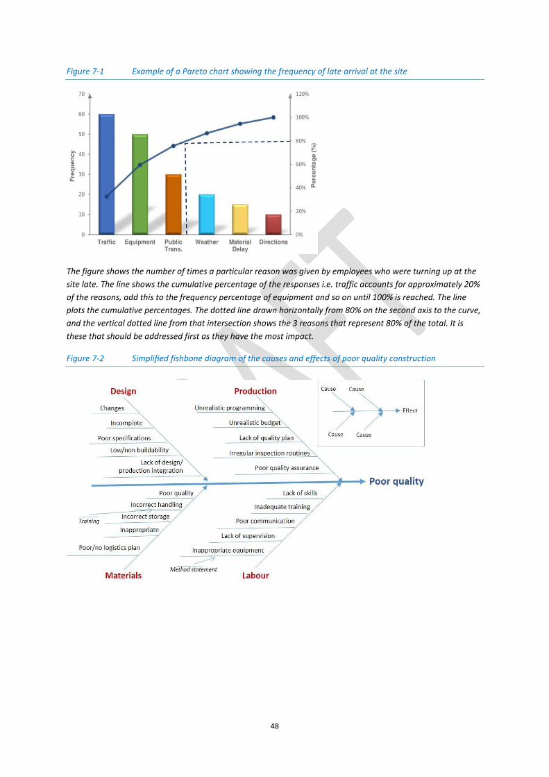
48
Figure 7-1 Example of a Pareto chart showing the frequency of late arrival at the site
The figure shows the number of times a particular reason was given by employees who were turning up at the
site late. The line shows the cumulative percentage of the responses i.e. traffic accounts for approximately 20%
of the reasons, add this to the frequency percentage of equipment and so on until 100% is reached. The line
plots the cumulative percentages. The dotted line drawn horizontally from 80% on the second axis to the curve,
and the vertical dotted line from that intersection shows the 3 reasons that represent 80% of the total. It is
these that should be addressed first as they have the most impact.
Figure 7-2 Simplified fishbone diagram of the causes and effects of poor quality construction

49
Figure 7-3 Example of a interrelationship digraph related to poor quality
7.6.2 Scenario planning
Scenario planning is identifying a specific set of uncertainties, different “realities” of what might
happen in the future and people’s perceptions of these. It is not about predicting events or
determining the most likely scenario, but developing several plausible stories that describe how the
environment in which an entity (e.g. an individual or organisation) lives or operates, may develop,
given certain future events, trends, and developments and then to explore possible ‘discontinuities’
and ‘surprises’
A scenario can be simply described as a storyline comprising a range of interconnected and
uncertain future events and their possible consequences. Scenarios are often employed for decision
making activities in which some parameters are uncertain or poorly defined.
7.7 A guide to creating a quality management plan (QMP)
The next sections take the reader through the construction process, identifying the steps that should
be taken and what may be included in the QMP. It is designed as a generic guide to creating a QMP,
which can be customised according to the corporate quality policy, the client’s requirements and the
type of project. It is important that responsibilities, compliance and risk factors are considered and
included for each category, with space for suitable action that is needed, plus the check that the
action has been taken/approved.
The categories to be included in a QMP are provided, along with suggested actions and links to
activities across the project and across the project teams. It is divided into the following sections:
1. Design and pre-construction activities 2. Construction/production quality activities 3. Post-construction quality activities
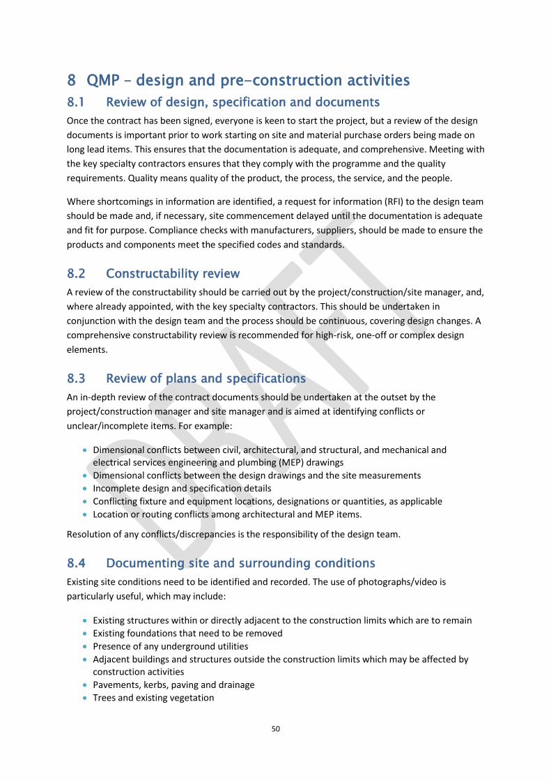
50
8 QMP – design and pre-construction activities
8.1 Review of design, specification and documents
Once the contract has been signed, everyone is keen to start the project, but a review of the design
documents is important prior to work starting on site and material purchase orders being made on
long lead items. This ensures that the documentation is adequate, and comprehensive. Meeting with
the key specialty contractors ensures that they comply with the programme and the quality
requirements. Quality means quality of the product, the process, the service, and the people.
Where shortcomings in information are identified, a request for information (RFI) to the design team
should be made and, if necessary, site commencement delayed until the documentation is adequate
and fit for purpose. Compliance checks with manufacturers, suppliers, should be made to ensure the
products and components meet the specified codes and standards.
8.2 Constructability review
A review of the constructability should be carried out by the project/construction/site manager, and,
where already appointed, with the key specialty contractors. This should be undertaken in
conjunction with the design team and the process should be continuous, covering design changes. A
comprehensive constructability review is recommended for high-risk, one-off or complex design
elements.
8.3 Review of plans and specifications
An in-depth review of the contract documents should be undertaken at the outset by the
project/construction manager and site manager and is aimed at identifying conflicts or
unclear/incomplete items. For example:
Dimensional conflicts between civil, architectural, and structural, and mechanical and electrical services engineering and plumbing (MEP) drawings
Dimensional conflicts between the design drawings and the site measurements
Incomplete design and specification details
Conflicting fixture and equipment locations, designations or quantities, as applicable
Location or routing conflicts among architectural and MEP items.
Resolution of any conflicts/discrepancies is the responsibility of the design team.
8.4 Documenting site and surrounding conditions
Existing site conditions need to be identified and recorded. The use of photographs/video is
particularly useful, which may include:
Existing structures within or directly adjacent to the construction limits which are to remain
Existing foundations that need to be removed
Presence of any underground utilities
Adjacent buildings and structures outside the construction limits which may be affected by construction activities
Pavements, kerbs, paving and drainage
Trees and existing vegetation

51
Above-ground utilities, including overhead power and telephone cables
Streams, culverts, groundwater/flooding potential
Access to the site
Condition of the existing pavements and road surfaces
Location of any bus stops close to the site.
8.5 Samples, submittals and procurement
Samples may be required as part of the tender award process if suppliers are being
considered/selected. After selection they may be needed to demonstrate compliance that the
supplier can produce the material/component to the required standard/specification.
A submittal register/file identifying the submittals and their due date should be compiled by the
project/construction/site manager as soon as possible. The submittal register should include details
of submittal review/approval processes, including that required for revision/re-submittal, as well as
the fabrication time, transportation and delivery to the site. The register should be kept by the
contractor at the site.
Submittal samples should be an indication of the level of material quality expected by the
client/design team. Mock-ups may be required to establish workmanship guidelines and will be
preserved to establish a quality base-line.
The contract will stipulate the submittal requirements, their procurement and approval process. All
variations or substitutions must be approved by the client and be in accordance with contract
requirements. Any variations should be accompanied by the reasons for the change.
The project/construction/site manager must ensure that all
purchased building materials, equipment, and supplies
conform to project requirements and conform to any
approved submittals. They should ensure that suppliers can
produce and deliver the materials/components on time, and
that they are suitably protected during loading, unloading and
storage on site. Material verification throughout the
production process is important, particularly for bricks, blocks,
timber components, structural steel, sanitary ware, drywall
tapes, drywall joint compounds, mastics, caulking, grout,
fasteners, welding supplies, and other consumable supplies.
8.6 Specialty contractor selection
Pre-qualification/selection processes should be followed where applicable. Assessments should be
made on the safety, quality, capability and capacity of a specialty contractor and their ability to meet
the cost parameters. A pre-construction sub-contractor meeting between the contractor and the
specialty contractors should ensure that all the parties are clear about the responsibility for quality
delivery.

52
8.7 Mock-ups
The contract will state any requirements for mock-ups. Further mock-ups may be necessary for high-
risk construction assemblies, either in-situ or freestanding. For example:
Exterior skin - particular attention shall be devoted to transitions and joins between dissimilar materials (windows to skin, skin to parapets, etc.). Construction details that do not conform to a manufacturer's standard details should be highlighted and cleared with the design team.
Roofing
Window and door penetrations
Pre-cast or GFRC panels
Drywall finish/texture
Wall/ceiling finishes
Floor finishes
Cabinets
Countertops and fixtures
Hardscape
Mock-up units, such as, bathrooms, kitchens on a multi-unit project.
First work-in-place will generally serve as a mock-up.
8.8 Factory/shop inspections
The project manager should provide the client, design team and other consultants with a draft list of
construction assemblies, equipment or materials for factory/shop for their review comment and,
where applicable, their written approval. The client and/or their representatives may wish to attend
and witness any critical destructive or non-destructive tests.
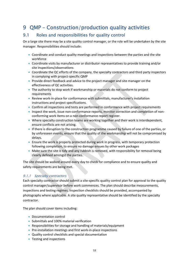
53
9 QMP – Construction/production quality activities
9.1 Roles and responsibilities for quality control
On a large site there may be a site quality control manager, or the role will be undertaken by the site
manager. Responsibilities should include:
Coordinate and conduct quality meetings and inspections between the parties and the site workforce
Coordinate visits by manufacturer or distributor representatives to provide training and/or site inspections/observations
Coordinate the QC efforts of the company, the specialty contractors and third party inspectors in complying with project-specific QMP
Provide direct feedback and advice to the project manager and site manager on the effectiveness of QC activities.
The authority to stop work if workmanship or materials do not conform to project requirements
Review work-in-place for conformance with submittals, manufacturer's installation instructions and project specifications.
Confirm all inspections and tests are performed in conformance with project requirements
Inspect the work, issue non-conformance reports, monitor correction and completion of non-conforming work items on a non-conformance report register.
Where specialty construction teams are working together and their work is interdependent, ensure conflicts are not arising.
If there is disruption to the construction programme caused by failure of one of the parties, or by unforeseen events, ensure that the quality of the workmanship will not be compromised by delays.
Ensure the work is properly protected during work in progress, with temporary protection following completion, to ensure no damage ensues by other work packages
Make sure the site is tidy and any rubbish is removed, with responsibility for removal being clearly defined amongst the parties.
The site should be walked around every day to check for compliance and to ensure quality and
safety requirements are being met.
9.1.1 Specialty contractors
Each specialty contractor should submit a site-specific quality control plan for approval to the quality
control manager/supervisor before work commences. The plan should describe measurements,
inspections and testing regimes. Inspection checklists should be provided, accompanied by
photographs where applicable. A site quality representative should be identified by the specialty
contractor.
The plan should cover items including:
Documentation control
Submittals and 100% material verification
Responsibilities for storage and handling of materials/equipment
Pre-installation meetings and first work-in-place inspections
Quality control checklists and special documentation
Testing and inspections

54
Procedures to be followed for any non-conformances
Progress photo frequency
As-built drawing requirements.
Quality control is equally important on smaller projects. Whilst more will be based on relationships
and trust, rather than documentation, never lose sight of what happens if things go wrong and
defects occur. Nobody wants bureaucratic procedures, but there must be a system in place that can
handle remedying defects and maintaining quality standards.
9.2 The 3 stages of quality control
The 3 stages are: Preparatory (pre commencement on site); Initial (first work-in-place) and Follow-up
(daily inspections). These 3 stages allow the contractor to plan, schedule and install work in an
orderly, consistent way that minimizes rework. Construction quality depends on effective planning,
coordination, communication, supervision and testing.
Preparatory – a pre-installation meeting, conducted by the project manager, should be convened,
involving the contractor, specialty contractors, client and design team (and other interested parties).
The meeting’s aim should be to prevent deficiencies rather that detect them. The project manager
should make the following documents available at the meeting:
Approved submittals, materials safety data sheets, and shop drawings
Manufacturer's installation instructions
Applicable building regulations and codes
Current contract drawings
Current contract specifications
Current schedule
Safety hazard analysis
Contractor's inspection checklists and inspection report forms
First work-in-place – the first work-in-place meeting an inspection should be undertaken prior to
commencement of the relevant activity. For a significant construction activity, the
meeting/inspection should involve the client (or their representative), a member of the design team,
relevant consultants, the site manager/trades supervisor and a manufacturer’s representative.
Follow-up – follow-up phase inspections should be conducted on a regular basis, preferably daily
using an inspection checklist if one is available. The follow-up ensures conformance, quality
workmanship, testing and safety considerations have been met. Also, that the required
certifications, calibrations and measurements are accurate.
Additional pre-installation and first work-in-place inspections will need to be carried out if there are
any significant changes to personnel, supervision on site, periods of inactivity or the quality of on-
going work is unacceptable.
9.3 Quality control manager activities
The quality management plan (QMP) should outline the inspections and tests required from the
contractor and specialty contractors to ensure conformance with the quality of materials,
workmanship, fit, finish, and performance as defined in the contract.

55
Implementation - All testing data should be shared with the site manager and specialty contractors’
quality manager(s).
Documentation - This should be maintained for all quality control activities, inspections and tests by
both the contractor’s quality control manager and that of the specialty contractors. It includes the
quality management plan, the inspection plan and log and any relevant checklists.
Inspections - The contractor’s quality manager should inspect, and verify (if appropriate) items that
will be covered up by subsequent work. Photographs should be taken of the work that will be
covered up.
Inspection and testing plan – This should cover both the contractor’s and the specialty contractors’
work. It will follow the same format as the log (see below). It is best practice to involve
manufacturer's representatives in inspections and approvals for high risk elements, e.g. roofing
systems and specialised installations.
Inspection and testing log – All inspections and tests should be recorded in the log, specifying details
of the test (e.g. description, location, date, performed by and so on) and any relevant remarks. The
log should be shared with/made available to the relevant sub-contractors.
Final inspection /snagging – the contractor’s quality control manager will inspect the work near
completion and produce a list of non-conforming items. The list should include the estimated
correction date and details of the follow-up inspection.
Final acceptance – this involves final system testing, system and sequence verification, O & M
manuals, delivery of recorded drawings and warranties, instruction and training procedures.
9.4 Non-conformance procedures
A non-conforming (or deficient) activity/material/component is one that does not meet the contract
requirements. Non-conforming items may be found by any member of the design or the contractor’s
team and should be documented in a non-conformance report/log. The items in this log need to be
tracked to ensure correction of the work/item and its acceptance recorded.
9.5 Zero defects
The contractor’s team, especially the quality control manager, needs to be aware of a zero-defect
policy the client may have or that has been included in the contract.

56
9.6 Digital photography
Photographs should be an integral part of each project-specific quality
management plan. Digital equipment needs to be readily available to
ensure a photographic record of construction progress and quality-
related issues are accomplished. As-built conditions should be
photographed during the course of construction. The photos should
be taken on a regular basis and labelled and stored accurately as they
can provide evidence of work conforming to contract (and other)
conditions. The digital library should be on a platform that allows
sharing across the production and client team. Pre-cover-up
photographs are particularly important.
9.7 Water intrusion/vulnerable materials
Water intrusion needs to be controlled and so early identification of this sort of problem is
important. The inspection regime set up by the quality control manager should include this type of
inspection on a daily basis. This is particularly important during long periods of inclement weather
and at critical stages of work such as the installation of critical building envelope components. Water
intrusion should be dealt with quickly and prevention steps taken e.g. temporary roofing, additional
floor protection and so on. Efforts should be made to ensure that vulnerable materials are not
exposed to elevated moisture conditions.
9.8 Key tasks and the importance of quality
There are a number of key tasks in the production process where quality control is particularly
important. Table 9-1 shows these tasks and their appropriate test requirements.
Table 9-1 Key tasks and their appropriate test requirements
Task Test requirements
Cut and fill Plate load test
Concrete foundations Concrete cubes
Drainage & Manholes Water test level and air test
Ground floor slabs Level survey to RL and formation concrete cubes
Masonry Panel to be built for inspection and kept
Masonry Setting out and openings
Masonry DPC and wall ties, lintels
Steelwork Plumb line and level checks
Roofing Visual inspection to confirm specifications and drawings, leak record
Electrical installation Dead and live load
Mechanical pipework Air pressure test
Gas pipework Air pressure test
Chlorination of water Sample taken of water in installed system
Fire alarms Sound check
Fire strategy Drawing to be issued to Building Control
Windows and doors Hose pipe test
Building air test Air leakage less than 10 1s/m2
Finishes Room to be set up as sample of acceptable finish

57
10 QMP – post-construction quality activities
10.1 Documentation
Records of quality-related actions such as inspections, testing, compliance etc. should be carefully archived, easily retrievable and part of the project’s permanent records. The storage should be protected from loss, fire, and flood. The records include:
Daily reports
Inspection reports
Test reports and logs
Inspecting technician's certifications, as applicable
As-built drawings
Approved submittals
Quality audit reports
Certifications of materials
Non-conformance reports and records of related remedial work and acceptance
Photo and video documentation
Required records of personnel qualifications, as applicable
Results of miscellaneous tests, inspections and examinations performed by any responsible party
Special process procedures, as applicable
Final inspections
Final system testing, as applicable
Commission reports, as applicable
Operation and Maintenance (O&M) Manuals
Warranties
Copies of local authority inspection reports
Copies of Certificates of Occupancy from building officials
10.2 Warranties
10.2.1 Defects
Failures in design/specification, or those due to poor materials or bad workmanship can lead to a
project not meeting the client’s expectations. Defects can be either patent or latent. Patent defects
can be discovered by ‘reasonable’ inspection. Latent defects may not immediately be apparent and
will not be found with ‘reasonable’ inspection. For example, problems with the foundations may not
become arise until several years after completion. Once the latent defect becomes apparent it is
referred to as a patent defect.
Once discovered and reported to the contractor, they need to be rectified in a reasonable time
before a certificate of practical completion can be issued. If the certificate is issued yet there are
defects outstanding, the contract administrator is liable for any problem caused by this action, e.g.
the calculation of liquidated damages.
The contractor will have warranties in place and will endeavour to satisfy their conditions and any
post-construction issues during the warranty period.

58
SECTION THREE

59
11 Relevant standards by work sections This section looks at the work sections across a project with the relevant standards shown for each sub-section; there are three types:
BS British Standard BS EN British Standard European Norm ASTM Globally recognised standard
11.1 Temporary works
Parts of the works that allow or enable construction of, protect, support or provide access to, the permanent works and which might or might not remain in
place at the completion of the works.
Type Description Requirements Quality issues Formwork A temporary mould into which
concrete is poured and formed. It is usually fabricated using timber, but it can also be constructed from steel, glass fibre reinforced plastic and other materials. Formwork may be part of the falsework construction and is used in four main areas; walls, columns, beams and slabs. When it is used for the underside of suspended slabs and beams it is known as soffit formwork.
There are 3 main types of formwork: engineered systems; timber, and; re-usable plastic.
Desired shape, size and fit according to the drawings/ specifications.
Select material to ensure required finish of the poured concrete.
Able to withstand the loading (wet and dry concrete) as specified.
Should be dismantled and moved as easily as possible so that construction of the building advances.
Ability to fit and fasten together both tightly and easily.
Should be simple to build.
Type and temperature of the concrete pour is important information.
The strength/loading of the formwork sides must comply with specifications, particularly important in terms of the initial dead load of wet concrete.
Sufficient strength reached before striking.
High with workmanship and inspection are necessary to ensure a high standard and appearance of the resulting concrete structure.
Damage to concrete on removal of formwork/falsework.
Falsework Falsework generally relates to the structural vertical support of concrete decks and so on.
Supports shuttering and formwork. Relevant standards PAS 8812:2016 Temporary works. Application of European Standards in design. Guide.

60
BS 5975:2008+A1:2011 Code of practice for temporary works procedures and the permissible stress design of falsework. BS 8410:2007 Code of practice for lightweight temporary cladding for weather protection and containment on construction works. BS EN 12813:2004 Temporary works equipment. Load bearing towers of prefabricated components. Particular methods of structural design. BS EN 12811-2:2004 Temporary works equipment. Information on materials BS EN 12811-1:2003 Temporary works equipment. Scaffolds. Performance requirements and general design BS EN 12811-3:2002 Temporary works equipment. Load testing BS 5974:2017 Planning, design, setting up and use of temporary suspended access equipment. Code of practice. BS EN 13374:2013 Temporary edge protection systems. Product specification. Test methods. BS 7909:2011 Code of practice for temporary electrical systems for entertainment and related purposes. BS EN 1004:2004 Mobile access and working towers made of prefabricated elements. Materials, dimensions, design loads, safety and performance requirements. BS EN 12063:1999 Execution of special geotechnical work. Sheet pile walls. BS 7962:2000 Black materials for masking existing road markings. Specification. BS 4363:1998+A1:2013 Specification for distribution assemblies for reduced low voltage electricity supplies for construction and building sites. BS 1139-4:1982 Metal scaffolding. Specification for prefabricated steel splitheads and trestles
Other types of temporary works such as excavation and earthworks are covered in 11.2.
11.2 Substructure
Substructure is defined as: All work below underside of screed or, where no screed exists, to the underside of lowest floor finishes including damp-proof
membrane, together with relevant excavations and foundations (this includes walls to basements designed as retaining walls).
The function of substructure is to “… transfer the load of the building to the ground and to isolate it horizontally from the ground.”
There are four types of substructure:
Foundations (up to and including the DPC)
Lowest floor assembly
Basement excavation
Basement retaining walls (up to and including DPC)
11.2.1 Foundations - shallow
Type Description Advantages Disadvantages Quality issues Pad Isolated footings, often used to
support a column. Constructed of a block or slab, which may be stepped to spread the load.
Less material needed.
Individual pad foundations may interact with each other.
Ground conditions.
Presence of water.

61
Strip Support a line of loads – a wall or a line of columns
Needs more material and reinforcement than pad footings.
Load calculation e.g. dead load, imposed load, wind load.
Minimum width related to type of soil.
Design needs to be approved by Building control.
Raft Concrete slab that spreads the load over a wide area. May be stiffened by ribs or beams within the foundation.
Can reduce differential settlements.
Can be used on soft or loose soils
Prone to edge erosion
Relevant standards BS 8004:2015 Code of practice for foundations. BS 8103-1:2011 Structural design of low-rise buildings. Code of practice for stability, site investigation, foundations, precast concrete floors and ground floor slabs for housing
Approved Document10 A Structure
11.2.2 Foundations – deep: piling
10 A series of Approved Documents constitute the Building Regulations produced by the government (https://www.planningportal.co.uk/info/200135/approved_documents)
Type Description Advantages Disadvantages Quality issues
Foundations (up
to and including
the DPC)
Column-like structures made from
steel, reinforced concrete or
timber. A piled foundation is where
the depth is three times that of the
breadth.
They are classified by their design
function – end-bearing, friction (or
a combination of both) – or by their
method of construction –
displacement (driven) or
replacement (bored).
Can transfer loads in relatively weak soil structures.
Can be precast to specifications.
Bearing capacity increases when screw piles are driven into granular soil.
Reinforcement needed for precast concrete piles – transporting and piling.
Heavy equipment necessary.
Difficult to determine the required pile length in advance.
Unsuitable for soils with poor drainage.
Vibrations from piling operations
Variability of ground conditions.
Knowledge of ground conditions _ detailed site investigation.
Contractor’s skill and experience.
Good quality materials.
Appropriate construction procedures.
Good workmanship and site supervision.
Programme and budget pressures.
Ground movements (traffic etc.) during concrete hardening.
Appropriate method for trimming pile head.

62
11.2.3 Basement excavation
Can be used when working over water.
may impact neighbouring structures.
Relevant standards BS EN ISO 22477-4:2018 Geotechnical investigation and testing. Testing of geotechnical structures. Testing of piles: dynamic load testing BS EN 1993-5:2007 Eurocode 3. Design of steel structures. Piling BS EN 12794:2005 Precast concrete products. Foundation piles. BS ISO 11886:2002 Building construction machinery and equipment. Pile driving and extracting equipment. Terminology and commercial specifications. BS EN 12063:1999 Execution of special geotechnical work. Sheet pile walls. BS EN 1997-1:2004+A1:2013 Eurocode 7. Geotechnical design. General rules BS 8008:1996+A1:2008 Safety precautions and procedures for the construction and descent of machine-bored shafts for piling and other purposes. BS 8004:2015 Code of practice for foundations. BS 8002:2015 Code of practice for earth retaining structures. ASTM D8169/D8169M - 18 Standard Test Methods for Deep Foundations Under Bi-Directional Static Axial Compressive Load. ASTM D4945 - 17 Standard Test Method for High-Strain Dynamic Testing of Deep Foundations. 15/30326284 DC BS EN 16907-2. Earthworks. Part 2. Classification of materials. Approved Document A Structure
Type Description Advantages Disadvantages Quality issues
Underpinning Mass concrete or
reinforced concrete
underpins may be used to
increase the depth of the
existing foundations.
Tried and tested methods available.
Poor specifications or structural engineering can cause collapse.
Soil conditions.
High water table.
Depth and quality of existing foundations.
State of existing building’s fabric or structure.
Sufficient information regarding the construction/state of existing building.
Ground-bearing concrete floors.
Party wall issues.
Soil, geology and hydrology.
Contractor inexperienced in basement construction.
Piling Reinforced concrete or
steel sheet piles can be
used.
Tried and tested methods available.
Need a permanent inner reinforced concrete wall or box to provide horizontal strength and waterproofing.
Needs space around the drilling head, thus there is a gap between the pile edge and the existing wall.
Pile size is limited by rig size which is restrained by the
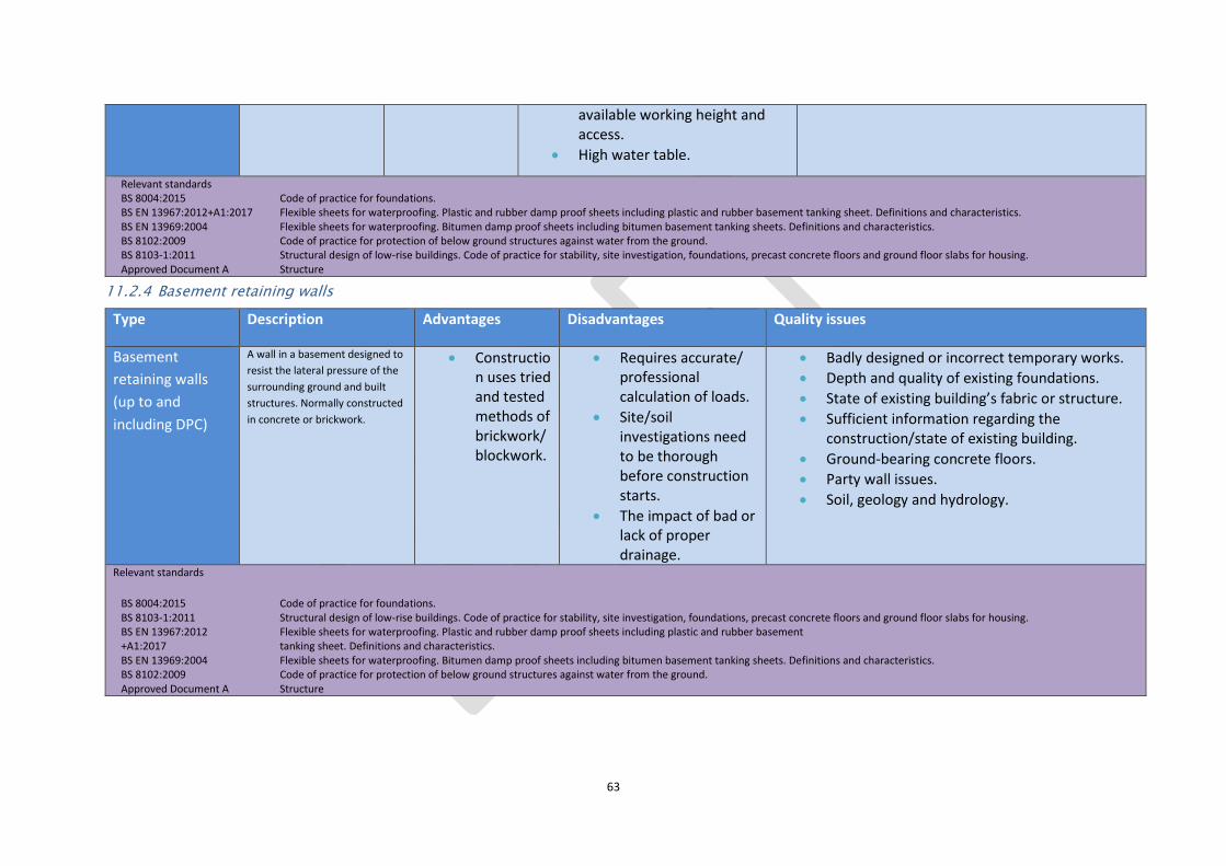
63
11.2.4 Basement retaining walls
available working height and access.
High water table.
Relevant standards BS 8004:2015 Code of practice for foundations. BS EN 13967:2012+A1:2017 Flexible sheets for waterproofing. Plastic and rubber damp proof sheets including plastic and rubber basement tanking sheet. Definitions and characteristics. BS EN 13969:2004 Flexible sheets for waterproofing. Bitumen damp proof sheets including bitumen basement tanking sheets. Definitions and characteristics. BS 8102:2009 Code of practice for protection of below ground structures against water from the ground. BS 8103-1:2011 Structural design of low-rise buildings. Code of practice for stability, site investigation, foundations, precast concrete floors and ground floor slabs for housing. Approved Document A Structure
Type Description Advantages Disadvantages Quality issues
Basement
retaining walls
(up to and
including DPC)
A wall in a basement designed to
resist the lateral pressure of the
surrounding ground and built
structures. Normally constructed
in concrete or brickwork.
Construction uses tried and tested methods of brickwork/ blockwork.
Requires accurate/ professional calculation of loads.
Site/soil investigations need to be thorough before construction starts.
The impact of bad or lack of proper drainage.
Badly designed or incorrect temporary works.
Depth and quality of existing foundations.
State of existing building’s fabric or structure.
Sufficient information regarding the construction/state of existing building.
Ground-bearing concrete floors.
Party wall issues.
Soil, geology and hydrology.
Relevant standards
BS 8004:2015 Code of practice for foundations. BS 8103-1:2011 Structural design of low-rise buildings. Code of practice for stability, site investigation, foundations, precast concrete floors and ground floor slabs for housing. BS EN 13967:2012 Flexible sheets for waterproofing. Plastic and rubber damp proof sheets including plastic and rubber basement +A1:2017 tanking sheet. Definitions and characteristics. BS EN 13969:2004 Flexible sheets for waterproofing. Bitumen damp proof sheets including bitumen basement tanking sheets. Definitions and characteristics. BS 8102:2009 Code of practice for protection of below ground structures against water from the ground. Approved Document A Structure

64
11.2.5 Diaphragm wall and embedded retaining walls
The design, specification and construction details of retaining walls must be provided by the project’s engineer. Quality (and safety) issues can arise with
backfilling, which can cause instability. Any pressure on the area immediately adjacent to the wall (surcharging) can create a horizontal force which may
destabilise the wall. The type of materials used for a retaining wall must depend on the load which is a crucial element. Soil type will need to be taken into
account as well as cost but aesthetics should always be secondary. The International Building Code requires retaining walls to be designed to ensure
stability against overturning, sliding, excessive foundation pressure and water uplift. There are four main types of retaining wall, each requiring careful
consideration to ensure that they are strong enough for the designed purpose: gravity; cantilever; sheet piling, and; anchored.
Type Description Advantages Disadvantages Quality issues
Gravity/
Crib
Rely on their mass/weight to
hold back a load. Gabions may
be used for this.
Easy to install and remove.
Crib walls: Can be built by hand; easy and quick to build; crib sections can be pre-cast; free draining; top level easily varied
Gabions: Can be built by hand; easy and quick to build; no specialist equipment required; rock fill may be locally sourced; free-draining; can be placed directly on soil.
Gabions: Possible loss of material through gabion; not suitable for varying ground levels; relatively low unit weight.
Crib walls: often requires a concrete base; uneconomic for short runs; relatively low unit weight.
Excessive water/moisture
Poor quality materials
Inappropriate choice of retaining wall/ techniques.
Level of mobilisation of passive earth resistance.
Poor/lack of guidance and supervision.
Lack of structural engineering drawings/advice/ specifications.
Proper drainage must be provided to reduce any hydrostatic pressure of ground water behind the wall.
Cantilever Made from mortared masonry or
reinforced concrete. The
reinforced base means that
there is vertical pressure from
the ground behind the wall,
Unobstructed open excavation.
Tiebacks below adjacent properties not required.
Excavation depth limited to 6 metres.
Not recommended for use next to adjacent buildings.

65
rather than horizontal. This type
of wall has an inverted ‘T’ shape.
Deep excavations may requires the rigidity of the wall to be increased considerably, limiting available space within the excavation.
Impact on surrounding structures.
Sheet piling Sheet piles are driven into the
ground with the added strength
of ground anchors with a cement
grout
Quicker than constructing reinforced concrete walls.
Narrow form of construction, thus maximising usable site space.
Suitable for all soil types.
No requirement for pre-excavation.
Relatively little disturbance of existing ground.
Immediate load bearing capacity.
Can be used on several projects.
Temporary structures rarely can be used for permanent structures.
Rocks or large boulders will impede piling.
Anchored Anchored by cables which are
secured by concrete Can be both slender and
withstand high loads.
Used where footing size is an issue.
Ideal for smaller areas that need earth retention.
Requires specialist equipment and qualified engineers.
Difficult to secure anchors in weak soil and/or at any great depth.
Can impact surrounding construction works.

66
Relevant standards ASTM C1372 - 17 Standard Specification for Dry-Cast Segmental Retaining Wall Units. BS EN 15258:2008 Precast concrete products. Retaining wall elements. BS 8002:2015 Code of practice for earth retaining structures. BS EN 1538:2010+A1:2015 Execution of special geotechnical works. Diaphragm walls. BS EN 16907-5 Draft for public comment Earthworks BS EN 771-4:2011+A1:2015 Specification for masonry units. Autoclaved aerated concrete masonry units BS 8006-1:2010+A1:2016 Code of practice for strengthened/reinforced soils and other fills. BS EN 1993-5:2007 Eurocode 3. Design of steel structures. Piling BS EN 16228-5:2014 Drilling and foundation equipment. Safety. Diaphragm walling equipment BS EN 1538:2010+A1:2015 Execution of special geotechnical works. Diaphragm walls. Approved Document A Structure
11.3 Superstructure
11.3.1 Stairs, walkways and balustrades
Type Description Requirements Quality issues
Utility stair A stair used for escape, access for maintenance, or purposes other than as the usual route for moving between levels on a day-to-day basis
Stairs may be constructed from a number of different materials including:
Timber
Brick
Stone
Concrete
Metal
Glass
Requirement K1 of the Approved Document K can be met by ensuring that the steepness, rise and going, handrails, headroom, length and width of any stairs, ladders and ramps between levels are appropriate to afford reasonable safety to people gaining access to and moving about buildings. Key considerations are:
Width
Length of flight
Handrails
The type and strength of the materials used need to meet the required use and loading.
The quality/strength/durability of the surface of the stair.
Poor installation which affects the integrity/safety of the stairway.
General access stair A stair intended for all users of a building on a day-to-day basis, as a normal route between levels.
Private stair A stair intended to be used for only one dwelling.
Protected stair A stair discharging through a final exit to a place of safety (including any exit passageway between the foot of the stair and the final exit) that is adequately enclosed with fire resisting construction.
Firefighting stair A protected stairway communicating with the accommodation area through a firefighting lobby.
Common stair An escape stair serving more than one flat

67
Guarding
Fire safety Relevant standards Approved Document B Part B Fire safety Approved Document K K1 Stairs, ladders and ramps; K2 Protection from falling; K3 Vehicle barriers and loading bays; K4 Protection against impact with glazing; K5 Additional provisions for glazing in buildings other than dwellings; K6 Protection against impact from and trapping by doors Approved document M Access to and use of buildings BS EN 16954:2018 Agglomerated stone. Slabs and cut-to-size products for flooring and stairs (internal and external). BS 5395-1:2010 Stairs. Code of practice for the design of stairs with straight flights and winders BS EN 15644:2008 Traditionally designed prefabricated stairs made of solid wood. Specifications and requirements. BS EN 14843:2007 Precast concrete products. Stairs. BS 585-1:1989 Wood stairs. Specification for stairs with closed risers for domestic use, including straight and winder flights and quarter or half landings BS 585-2:1985 Wood stairs. Specification for performance requirements for domestic stairs constructed of wood-based materials BS 5395-2:1984 Stairs, ladders and walkways. Code of practice for the design of helical and spiral stairs BS 5578-2:1978 Building construction - stairs. Modular co-ordination: specification for co-ordinating dimensions for stairs and stair openings BS 4592-0:2006+A1:2012 Flooring, stair treads and handrails for industrial use. Common design requirements and recommendations for installation BS 4592-3:2006 Industrial type flooring and stair treads. Cold formed metal planks. Specification BS 8203:2017 Code of practice for installation of resilient floor coverings. BS EN 13318:2000 Screed material and floor screeds. Definitions. BS EN ISO 16283-2:2018 Acoustics. Field measurement of sound insulation in buildings and of building elements. Impact sound insulation BS 5385-1:2018 Wall and floor tiling. Design and installation of ceramic, natural stone and mosaic wall tiling in normal internal conditions. Code of practice BS EN 15254-7:2018 Extended application of results from fire resistance tests. Non-loadbearing ceilings. Metal sandwich panel construction BS EN 115-1:2017 Safety of escalators and moving walks. Construction and installation BS 9991:2015 Fire safety in the design, management and use of residential buildings. Code of practice. BS 9266:2013 Design of accessible and adaptable general needs housing. Code of practice. BS EN ISO 2867:2011 Earth-moving machinery. Access systems. BS 6349-2:2010 Maritime works. Code of practice for the design of quay walls, jetties and dolphins BS 8103-3:2009 Structural design of low-rise buildings. Code of practice for timber floors and roofs for housing BS 5385-5:2009 Wall and floor tiling. Design and installation of terrazzo, natural stone and agglomerated stone tile and slab flooring. Code of practice BS EN 516:2006 Prefabricated accessories for roofing. Installations for roof access. Walkways, treads and steps. BS EN 1168:2005+A3:2011 Precast concrete products. Hollow core slabs. BS EN 14716:2004 Stretched ceilings. Requirements and test methods. BS 8204-4:2004+A1:2011 Screeds, bases and in situ floorings. Cementitious terrazzo wearing surfaces. Code of practice BS 8204-3:2004+A2:2011 Screeds, bases and in situ floorings. Polymer modified cementitious levelling screeds and wearing screeds. Code of practice BS 8204-5:2004+A1:2011 Screeds, bases and in situ floorings. Mastic asphalt underlays and wearing surfaces. Code of practice BS 8204-1:2003+A1:2009 Screeds, bases and in situ floorings. Concrete bases and cementitious levelling screeds to receive floorings. Code of practice BS 8204-2:2003+A2:2011 Screeds, bases and in situ floorings. Concrete wearing surfaces. Code of practice BS 8000-9:2003 Workmanship on building sites. Cementitious levelling screeds and wearing screeds. Code of practice BS EN 13892-5:2003 Methods of test for screed materials. Determination of wear resistance to rolling wheel of screed material for wearing layer BS EN 13892-7:2003 Methods of test for screed materials. Determination of wear resistance to rolling wheel of screed material with floor coverings BS EN 14231:2003 Natural stone test methods. Determination of the slip resistance by means of the pendulum tester. BS 8204-7:2003 Screeds, bases and in-situ floorings. Pumpable self-smoothing screeds. Code of practice BS EN 13892-1:2002 Methods of test for screed materials. Sampling, making and curing specimens for test BS EN 13892-2:2002 Methods of test for screed materials. Determination of flexural and compressive strength BS EN 13892-4:2002 Methods of test for screed materials. Determination of wear resistance-BCA
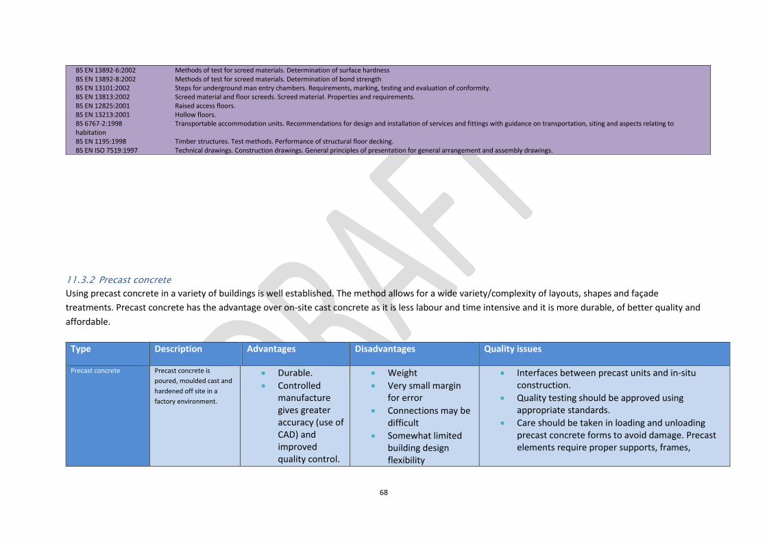
68
11.3.2 Precast concrete
Using precast concrete in a variety of buildings is well established. The method allows for a wide variety/complexity of layouts, shapes and façade
treatments. Precast concrete has the advantage over on-site cast concrete as it is less labour and time intensive and it is more durable, of better quality and
affordable.
BS EN 13892-6:2002 Methods of test for screed materials. Determination of surface hardness BS EN 13892-8:2002 Methods of test for screed materials. Determination of bond strength BS EN 13101:2002 Steps for underground man entry chambers. Requirements, marking, testing and evaluation of conformity. BS EN 13813:2002 Screed material and floor screeds. Screed material. Properties and requirements. BS EN 12825:2001 Raised access floors. BS EN 13213:2001 Hollow floors. BS 6767-2:1998 Transportable accommodation units. Recommendations for design and installation of services and fittings with guidance on transportation, siting and aspects relating to habitation BS EN 1195:1998 Timber structures. Test methods. Performance of structural floor decking. BS EN ISO 7519:1997 Technical drawings. Construction drawings. General principles of presentation for general arrangement and assembly drawings.
Type Description Advantages Disadvantages Quality issues
Precast concrete Precast concrete is
poured, moulded cast and
hardened off site in a
factory environment.
Durable.
Controlled manufacture gives greater accuracy (use of CAD) and improved quality control.
Weight
Very small margin for error
Connections may be difficult
Somewhat limited building design flexibility
Interfaces between precast units and in-situ construction.
Quality testing should be approved using appropriate standards.
Care should be taken in loading and unloading precast concrete forms to avoid damage. Precast elements require proper supports, frames,
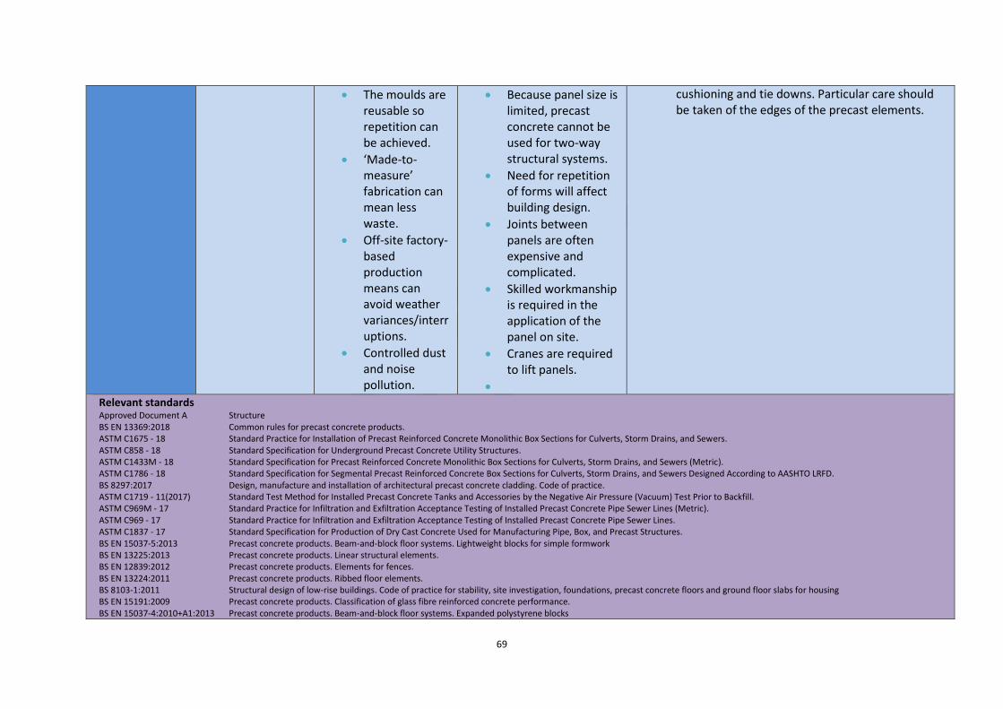
69
The moulds are reusable so repetition can be achieved.
‘Made-to-measure’ fabrication can mean less waste.
Off-site factory-based production means can avoid weather variances/interruptions.
Controlled dust and noise pollution.
Because panel size is limited, precast concrete cannot be used for two-way structural systems.
Need for repetition of forms will affect building design.
Joints between panels are often expensive and complicated.
Skilled workmanship is required in the application of the panel on site.
Cranes are required to lift panels.
cushioning and tie downs. Particular care should be taken of the edges of the precast elements.
Relevant standards Approved Document A Structure BS EN 13369:2018 Common rules for precast concrete products. ASTM C1675 - 18 Standard Practice for Installation of Precast Reinforced Concrete Monolithic Box Sections for Culverts, Storm Drains, and Sewers. ASTM C858 - 18 Standard Specification for Underground Precast Concrete Utility Structures. ASTM C1433M - 18 Standard Specification for Precast Reinforced Concrete Monolithic Box Sections for Culverts, Storm Drains, and Sewers (Metric). ASTM C1786 - 18 Standard Specification for Segmental Precast Reinforced Concrete Box Sections for Culverts, Storm Drains, and Sewers Designed According to AASHTO LRFD. BS 8297:2017 Design, manufacture and installation of architectural precast concrete cladding. Code of practice. ASTM C1719 - 11(2017) Standard Test Method for Installed Precast Concrete Tanks and Accessories by the Negative Air Pressure (Vacuum) Test Prior to Backfill. ASTM C969M - 17 Standard Practice for Infiltration and Exfiltration Acceptance Testing of Installed Precast Concrete Pipe Sewer Lines (Metric). ASTM C969 - 17 Standard Practice for Infiltration and Exfiltration Acceptance Testing of Installed Precast Concrete Pipe Sewer Lines. ASTM C1837 - 17 Standard Specification for Production of Dry Cast Concrete Used for Manufacturing Pipe, Box, and Precast Structures. BS EN 15037-5:2013 Precast concrete products. Beam-and-block floor systems. Lightweight blocks for simple formwork BS EN 13225:2013 Precast concrete products. Linear structural elements. BS EN 12839:2012 Precast concrete products. Elements for fences. BS EN 13224:2011 Precast concrete products. Ribbed floor elements. BS 8103-1:2011 Structural design of low-rise buildings. Code of practice for stability, site investigation, foundations, precast concrete floors and ground floor slabs for housing BS EN 15191:2009 Precast concrete products. Classification of glass fibre reinforced concrete performance. BS EN 15037-4:2010+A1:2013 Precast concrete products. Beam-and-block floor systems. Expanded polystyrene blocks

70
BS EN 15258:2008 Precast concrete products. Retaining wall elements. BS EN 15037-3:2009+A1:2011 Precast concrete products. Beam-and-block floor systems. Clay blocks BS 6073-2:2008 Precast concrete masonry units. Guide for specifying precast concrete masonry units BS EN 15435:2008 Precast concrete products. Normal weight and lightweight concrete shuttering blocks. Product properties and performance. BS EN 15037-1:2008 Precast concrete products. Beam-and-block floor systems. Beams BS EN 15498:2008 Precast concrete products. Wood-chip concrete shuttering blocks. Product properties and performance. BS EN 15050:2007+A1:2012 Precast concrete products. Bridge elements. BS EN 14843:2007 Precast concrete products. Stairs. BS EN 14844:2006+A2:2011 Precast concrete products. Box culverts. BS EN 14992:2007+A1:2012 Precast concrete products. Wall elements. BS EN 14991:2007 Precast concrete products. Foundation elements. BS EN 13747:2005+A2:2010 Precast concrete products. Floor plates for floor systems. BS 7533-3:2005+A1:2009 Pavements constructed with clay, natural stone or concrete pavers. Code of practice for laying precast concrete paving blocks and clay pavers for flexible pavements BS EN 1168:2005+A3:2011 Precast concrete products. Hollow core slabs. BS EN 12629-6:2004+A1:2010 Machines for the manufacture of constructional products from concrete and calcium-silicate. Safety. Stationary and mobile equipment for the manufacture of precast reinforced products BS EN 12794:2005 Precast concrete products. Foundation piles. BS EN 14649:2005 Precast concrete products. Test method for strength retention of glass fibres in cement and concrete (SIC test). BS EN 14474:2004 Precast concrete products. Concrete with wood-chips as aggregate. Requirements and test methods. BS EN 12843:2004 Precast concrete products. Masts and poles. BS EN 13693:2004+A1:2009 Precast concrete products. Special roof elements. BS EN 12737:2004+A1:2007 Precast concrete products. Floor slats for livestock. BS EN 13198:2003 Precast concrete products. Street furniture and garden products. BS 7533-8:2003 Pavements constructed with clay, natural stone or concrete pavers. Guide for the structural design of lightly trafficked pavements of precast concrete flags and natural stone flags BS 7533-2:2001 Pavements constructed with clay, natural stone or concrete pavers. Guide for the structural design of lightly trafficked pavements constructed of clay pavers or precast concrete paving blocks BS 7533-1:2001 Pavements constructed with clay, natural stone or concrete pavers. Guide for the structural design of heavy duty pavements constructed of clay pavers or precast concrete paving blocks BS 7533-6:1999 Pavements constructed with clay, natural stone or concrete pavers. Code of practice for laying natural stone, precast concrete and clay kerb units BS EN 1169:1999 Precast concrete products. General rules for factory production control of glass-fibre reinforced cement. BS EN 1170-2:1998 Precast concrete products. Test method for glass-fibre reinforced cement. Measuring the fibre content in fresh GRC, 'Wash out test' BS EN 1170-1:1998 Precast concrete products. Test method for glass-fibre reinforced cement. Measuring the consistency of the matrix. 'Slump test' method BS EN 1170-3:1998 Precast concrete products. Test method for glass-fibre reinforced cement. Measuring the fibre content of sprayed GRC BS EN 1170-4:1998 Precast concrete products. Test method for glass-fibre reinforced cement. Measuring bending strength. 'Simplified bending test' method BS EN 1170-5:1998 Precast concrete products. Test method for glass-fibre reinforced cement. Measuring bending strength, "complete bending test" method BS EN 1170-6:1998 Precast concrete products. Test method for glass-fibre reinforced cement. Determination of the absorption of water by immersion and determination of the dry density BS EN 1170-7:1998 Precast concrete products. Test method for glass-fibre reinforced cement. Measurement of extremes of dimensional variations due to moisture content ISO 9883:1993 Performance standards in building. Performance test for precast concrete floors. Behaviour under concentrated load. ISO 9882:1993 Performance standards in building. Performance test for precast concrete floors. Behaviour under non-concentrated load. BS 8000-2.2:1990 Workmanship on building sites. Code of practice for concrete work. Sitework with in situ and precast concrete BS 5642-2:1983+A1:2014 Sills, copings and cappings. Specification for copings and cappings of precast concrete, cast stone, clayware, slate and natural stone BS 5642-1:1978+A1:2014 Sills, copings and cappings. Specification for window sills of precast concrete, cast stone, clayware, slate and natural stone BS ISO 13270:2013 Steel fibres for concrete. Definitions and specifications. BS 8298-3:2010 Code of practice for the design and installation of natural stone cladding and lining. Stone-faced pre-cast concrete cladding systems BS EN 1857:2010 Chimneys. Components. Concrete flue liners. BS EN 1858:2008+A1:2011 Chimneys. Components. Concrete flue blocks. BS EN 1739:2007 Determination of shear strength for in-plane forces of joints between prefabricated components of autoclaved aerated concrete or lightweight aggregate concrete with open structure.

71
11.3.3 Precast/composite concrete
The term composite is used when concrete and one or more other materials are used in its fabrication, e.g. steel, timber and plastic. Using these other
materials makes use of different characteristics. For example, steel, which, unlike concrete, is very strong in tension, thus the combined characteristics of
compression and resistance to tension.
BS EN 13791:2007 Assessment of in-situ compressive strength in structures and pre-cast concrete components. BS EN 1992-1-1:2004+A1:2014 Eurocode 2: Design of concrete structures. General rules and rules for buildings BS 5911-6:2004+A1:2010 Concrete pipes and ancillary concrete products. Specification for road gullies and gully cover slabs BS EN 13295:2004 Products and systems for the protection and repair of concrete structures.Test methods. Determination of resistance to carbonation. BS 7533-11:2003 Pavements constructed with clay, natural stone or concrete pavers. Code of practice for the opening, maintenance and reinstatement of pavements of concrete, clay and natural stone BS EN 1339:2003 Concrete paving flags. Requirements and test methods. BS EN 1338:2003 Concrete paving blocks. Requirements and test methods. BS EN 1340:2003 Concrete kerb units. Requirements and test methods. BS EN 1917:2002 Concrete manholes and inspection chambers, unreinforced, steel fibre and reinforced. BS EN 1916:2002 Concrete pipes and fittings, unreinforced, steel fibre and reinforced. BS 5911-4:2002+A2:2010 Concrete pipes and ancillary concrete products. Specification for unreinforced and reinforced concrete inspection chambers (complementary to BS EN 1917:2002) BS EN 1740:1998 Performance test for prefabricated reinforced components made of autoclaved aerated concrete or lightweight aggregate concrete with open structure under predominantly longitudinal load (vertical components). BS EN 1737:1998 Determination of shear strength of welded joints of reinforcement mats or cages for prefabricated components made of autoclaved aerated concrete or lightweight aggregate concrete with open structure. BS EN 1742:1998 Determination of shear strength between different layers of multilayer components made of autoclaved aerated concrete or lightweight aggregate concrete with open structure. BS EN 1741:1998 Determination of shear strength for out-of-plane forces of joints between prefabricated components made of autoclaved aerated concrete or lightweight aggregate concrete with open structure. BS 1881-208:1996 Testing concrete. Recommendations for the determination of the initial surface absorption of concrete BS 8000-2.1:1990 Workmanship on building sites. Code of practice for concrete work. Mixing and transporting concrete BS 6579-8:1987 Safety fences and barriers for highways. Specification for concrete safety barriers
Type Description Advantages Disadvantages Quality issues
Precast
composite
concrete
A combination of concrete and other components to provide different characteristics to concrete-only components.
Can be lightweight.
Very small margin for error
Connections may be difficult
Interfaces between precast units and in-situ construction.
Quality testing should be approved using appropriate standards.
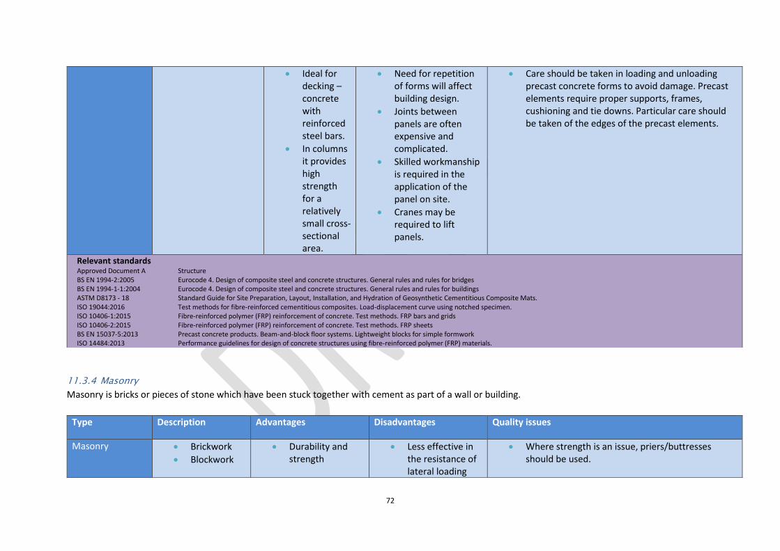
72
11.3.4 Masonry
Masonry is bricks or pieces of stone which have been stuck together with cement as part of a wall or building.
Ideal for decking – concrete with reinforced steel bars.
In columns it provides high strength for a relatively small cross-sectional area.
Need for repetition of forms will affect building design.
Joints between panels are often expensive and complicated.
Skilled workmanship is required in the application of the panel on site.
Cranes may be required to lift panels.
Care should be taken in loading and unloading precast concrete forms to avoid damage. Precast elements require proper supports, frames, cushioning and tie downs. Particular care should be taken of the edges of the precast elements.
Relevant standards Approved Document A Structure BS EN 1994-2:2005 Eurocode 4. Design of composite steel and concrete structures. General rules and rules for bridges BS EN 1994-1-1:2004 Eurocode 4. Design of composite steel and concrete structures. General rules and rules for buildings ASTM D8173 - 18 Standard Guide for Site Preparation, Layout, Installation, and Hydration of Geosynthetic Cementitious Composite Mats. ISO 19044:2016 Test methods for fibre-reinforced cementitious composites. Load-displacement curve using notched specimen. ISO 10406-1:2015 Fibre-reinforced polymer (FRP) reinforcement of concrete. Test methods. FRP bars and grids ISO 10406-2:2015 Fibre-reinforced polymer (FRP) reinforcement of concrete. Test methods. FRP sheets BS EN 15037-5:2013 Precast concrete products. Beam-and-block floor systems. Lightweight blocks for simple formwork ISO 14484:2013 Performance guidelines for design of concrete structures using fibre-reinforced polymer (FRP) materials.
Type Description Advantages Disadvantages Quality issues
Masonry Brickwork
Blockwork
Durability and strength
Less effective in the resistance of lateral loading
Where strength is an issue, priers/buttresses should be used.

73
11.3.5 Carpentry
This is a skilled trade which involves cutting, shaping and installation of building materials during the construction of buildings, timber bridges, concrete
formwork and so on.
Natural stone
Masonry systems: external leaf system; internal leaf system; partition system; freestanding wall leaf system
High thermal mass and good acoustic insulation.
Cavity acts as insulation and a vapour barrier.
Does not require finishing/ decorating.
Inexpensive to maintain and repair.
Fire resistant.
and/or tension forces.
Heavy, requiring strong foundations.
May be prone to frost damage, joint disintegration and discolouration.
The mortar mix needs to be appropriate, meeting the relevant standards.
Frequent inspections to ensure quality standards are met.
Brickwork reference panels can provide quality guidelines.
Ensure consistent pointing.
Ensure consistent quality, colour and strength.
Only specified admixtures (BS EN 934-3:2009+A1:2012) should be used in the mortar.
Rusting/failure of ties.
Length of wall ties meet specifications in Approved Document A of the Building Regulations (Table 5).
Relevant standards Approved Document A Structure Eurocode 6 Structure Part 1–1, General rules for reinforced and unreinforced masonry structures; Part 1–2, Structural fire design; Part 2, Design considerations, selection of materials and execution of masonry; Part 3, Simplified calculation methods for unreinforced masonry structures There are a very large number of standards related to masonry; these can be found in Appendix One.
Type Description Advantages Disadvantages Quality issues

74
11.3.6 Cladding and covering
Cladding is any material used to cover a structure's exterior. It is mainly used to stop wind and rain from entering the building. Cladding can also provide
sound and thermal insulation as well as fire resistance. It can make a building’s exterior more attractive.
Carpentry Types of carpentry: rough; framing; formwork; roofing, joister, trim, cabinet maker.
Timber structures: panels; panel diaphragms;
Less embodied energy
Strength of panels built up of sheets.
Compared to steel: more flexible; more energy efficient.
Wood studs may warp, rot, shrink, crack, or split
Wastage due to imperfections.
Compared to steel: will burn;
Adequate storage facilities to prevent warping.
Inspection of timber before use and once constructed.
Ensure that timber meets quality and strength specifications.
Lateral loads should be clearly stated for a panel roof-deck system or any other timber diaphragm wall.
Relevant standards BS 8000-5:1990 Workmanship on building sites. Code of practice for carpentry, joinery and general fixings BS 6100-8:2007 Building and civil engineering. Vocabulary. Work with timber and wood-based panels BS 3087-13:1991 Pliers and nippers. Specification for dimensions and test values of carpenter's pincers
Type Description Advantages Disadvantages Quality issues
Cladding Attached to a building's framework or an intermediate layer of battens or spacers.
It can be made of: Wood, metal, brick, vinyl, composite materials that can include aluminium,
Aesthetic.
Weather proof.
Insulation.
Fire resistance.
Constructed incorrectly can create a fire hazard.
Cost.
Construction time.
Repair costs.
Check warranty policies/schedules.
Compliance with and manufacturer’s installation specifications.
Regular inspections required, including spot checks of structure, brackets and other components.
Contractor’s skill and experience.

75
wood, blends of cement and recycled polystyrene, straw fibres.
Types: Curtain walling; Sandwich panels; Patent glazing; Rainscreen; Timber cladding; Metal profile cladding; Tensile fabric coverings; Brick slips; Tile hanging; Shakes and shingle; uPVC
Condensation may build up.
Relevant standards Approved Document A Structure Approved Document B Fire safety BS 8297:2017 Design, manufacture and installation of architectural precast concrete cladding. Code of practice. BS 5427:2016+A1:2017 Code of practice for the use of profiled sheet for roof and wall cladding on buildings. BS 5534:2014+A2:2018 Slating and tiling for pitched roofs and vertical cladding. Code of practice. BS EN 12326-1:2014 Slate and stone for discontinuous roofing and external cladding. Specifications for slate and carbonate slate BS EN 14783:2013 Fully supported metal sheet and strip for roofing, external cladding and internal lining. Product specification and requirements. BS EN 491:2011 Concrete roofing tiles and fittings for roof covering and wall cladding. Test methods. BS EN 490:2011+A1:2017 Concrete roofing tiles and fittings for roof covering and wall cladding. Product specifications. BS 8298-3:2010 Code of practice for the design and installation of natural stone cladding and lining. Stone-faced pre-cast concrete cladding systems BS 8410:2007 Code of practice for lightweight temporary cladding for weather protection and containment on construction works. BS EN 14782:2006 Self-supporting metal sheet for roofing, external cladding and internal lining. Product specification and requirements. BS 8298:1994 Code of practice for design and installation of natural stone cladding and lining. ISO 14:1982 Asbestos-cement products. Asbestos-cement-cellulose corrugated sheets and fittings for roofing and cladding ISO 14:1982 Asbestos-cement products. Trapezoidal section sheets for roofing and cladding BS 4904:1978 Specification for external cladding colours for building purposes. BS EN ISO 12631:2017 Thermal performance of curtain walling. Calculation of thermal transmittance. BS EN 1364-5:2017 Fire resistance tests for non-loadbearing elements. Air transfer grilles BS ISO 17738-1:2017 Thermal insulation products. Exterior insulation and finish systems. Materials and systems ASTM C1729 - 17 Standard Specification for Aluminum Jacketing for Insulation. ASTM C1729M - 17 Standard Specification for Aluminum Jacketing for Insulation. BS EN 16758:2016 Curtain walling. Determination of the strength of sheared connections. Test method and requirements. BS EN 14019:2016 Curtain Walling. Impact resistance. Performance requirements. BS EN 14509:2013 Self-supporting double skin metal faced insulating panels. Factory made products. Specifications. BS 8000-6:2013 Workmanship on building sites. Code of practice for slating and tiling of roofs and claddings BS EN 1304:2013 Clay roofing tiles and fittings. Product definitions and specifications. BS EN 505:2013 Roofing products from metal sheet. Specification for fully supported roofing products of steel sheet. BS EN 16301:2013 Natural stone test methods. Determination of sensitivity to accidental staining. BS EN 12467:2012+A2:2018 Fibre-cement flat sheets. Product specification and test methods.

76
11.3.7 Roofing
11.3.7.1 Roof coverings
Constructions which may consist of one or more layers of material, but does not refer to the roof structure as a whole. Roof size and shape often dictate
material and system selection.
BS EN 13381-6:2012 Test methods for determining the contribution to the fire resistance of structural members. Applied protection to concrete filled hollow steel columns BS EN 14617-12:2012 Agglomerate stone. Test methods. Determination of dimensional stability BS EN 771-3:2011+A1:2015 Specification for masonry units. Aggregate concrete masonry units (Dense and lightweight aggregates) BS EN 771-5:2011+A1:2015 Specification for masonry units. Manufactured stone masonry units BS EN 544:2011 Bitumen shingles with mineral and/or synthetic reinforcements. Product specification and test methods. BS EN 13050:2011 Curtain Walling. Watertightness. Laboratory test under dynamic condition of air pressure and water spray. BS 6100-6:2008 Building and civil engineering. Vocabulary. Construction parts BS EN 14992:2007+A1:2012 Precast concrete products. Wall elements. NA to BS EN 1991-1-5:2003 UK National Annex to Eurocode 1. Actions on structures. General actions BS 6093:2006+A1:2013 Design of joints and jointing in building construction. Guide. BS EN 1991-1-5:2003 Eurocode 1. Actions on structures. General actions BS EN 12152:2002 Curtain walling. Air permeability. Performance requirements and classification. BS EN 13364:2002 Natural stone test methods. Determination of the breaking load at dowel hole. BS 8219:2001+A1:2013 Installation of sheet roof and wall coverings. Profiled fibre cement. Code of practice. BS 6915:2001+A1:2014 Design and construction of fully supported lead sheet roof and wall coverings. Code of practice. BS EN 13051:2001 Curtain walling. Watertightness. Site test. BS EN 13116:2001 Curtain walling. Resistance to wind load. Performance requirements. BS EN 12179:2000 Curtain walling. Resistance to wind load. Test method. BS EN 12153:2000 Curtain walling. Air permeability. Test method. BS EN 12155:2000 Curtain walling. Watertightness. Laboratory test under static pressure. BS EN 12154:2000 Curtain walling. Watertightness. Performance requirements and classification. BS 5493:1977 Code of practice for protective coating of iron and steel structures against corrosion. CP 143-10:1973 Code of practice for sheet roof and wall coverings. Code of practice for sheet roof and wall coverings. Galvanized corrugated steel. Metric units CP 143-15:1973 Code of practice for sheet roof and wall coverings. Code of practice for sheet roof and wall coverings. Aluminium. Metric units CP 143-12:1970 Code of practice for sheet roof and wall coverings. Code of practice for sheet roof and wall coverings. Copper. Metric units
Type Description Advantages Disadvantages Quality issues
Tiles Roof tiles are either plain or interlocking
Roof tiles are traditionally made from clay and commonly measure 256mm x
Small tiles are easy to handle and transport.
Interlocking tiles reduce the
Double-lapped tiles can make the roof heavy, slow to lay and therefore
Incorrect or inadequate flashing put in place.
Ensure adequate nailing/fixing is taking place.

77
165mm. They need to be double-lapped.
Single-lapped tiles are interlocking with a tongue and groove joint.
weight of the roof (compared to double lapping).
relatively expensive.
Single-lapped tiles require a larger baton size and to be fixed by a clip or nail.
Poor cutting around roof vents or other protuberances.
Integration with the rest of the building or neighbouring property.
Drainage criteria associated with roof type.
Slates Slate is a natural material that is that is dense, strong, acid resistant
and non-absorptive.
Artificial slates are also available.
Impervious to freeze/thaw cycles.
Fire resistant.
Aesthetically pleasing.
Can be laid on roofs with a pitch as low as
30.
It is necessary to nail every slate which increases time and cost.
Double lapping requirement means that slate roofs are heavier.
Artificial slate is cheaper but do not last as long as real slate.
Wood shingles
and shakes
Shingles are sawn, shakes split.
Although they are naturally durable, timber preservative treatment is usually applied.
Renewable source and therefore sustainable.
Fire retardant treatment may also be required.
Fixings should be stainless steel and care should be taken with acidic run–off from cedar shingles.
Sheet
coverings
These are used for flat roofs.
Materials used include bituminous felt, asphalt and metal (e.g. lead or copper).
Metal sheets are mould and fungus resistance
Poor longevity of flat roofs.
Prone to weakness when

78
Easier to fit than tiles.
the sheets are bent or penetrated by ducts, flues etc.
Possible weakness at joints or seams.
Large unit sizes requiring adequate manpower.
Relevant standards
BS EN 12691:2018 Flexible sheets for waterproofing. Bitumen, plastic and rubber sheets for roof waterproofing. Determination of resistance to impact.
ASTM E1592 - 05(2017) Standard Test Method for Structural Performance of Sheet Metal Roof and Siding Systems by Uniform Static Air Pressure Difference.
ASTM D5636/D5636M (2017) Standard Test Method for Low Temperature Unrolling of Felt or Sheet Roofing and Waterproofing Materials.
BS EN 12039:2016 Flexible sheets for waterproofing. Bitumen sheets for roof waterproofing. Determination of adhesion of granules.
BS 5427:2016+A1:2017 Code of practice for the use of profiled sheet for roof and wall cladding on buildings.
BS EN 13859-1:2014 Flexible sheets for waterproofing. Definitions and characteristics of underlays. Underlays for discontinuous roofing
BS EN 16240:2013 Light transmitting flat solid polycarbonate (PC) sheets for internal and external use in roofs, walls and ceilings. Requirements and test methods.
BS EN 13707:2013 Flexible sheets for waterproofing. Reinforced bitumen sheets for roof waterproofing. Definitions and characteristics.
BS EN 1844:2013 Flexible sheets for waterproofing. Determination of resistance to ozone. Plastic and rubber sheets for roof waterproofing.
BS EN 12311-2:2013 Flexible sheets for waterproofing. Determination of tensile properties. Plastic and rubber sheets for roof waterproofing
BS EN 12316-2:2013 Flexible sheets for waterproofing. Determination of peel resistance of joints. Plastic and rubber sheets for roof waterproofing
BS EN 495-5:2013 Flexible sheets for waterproofing. Determination of foldability at low temperature. Plastic and rubber sheets for roof waterproofing
BS EN 14783:2013 Fully supported metal sheet and strip for roofing, external cladding and internal lining. Product specification and requirements.
BS EN 1109:2013 Flexible sheets for waterproofing. Bitumen sheets for roof waterproofing. Determination of flexibility at low temperature.

79
BS EN 505:2013 Roofing products from metal sheet. Specification for fully supported roofing products of steel sheet.
BS EN 502:2013 Roofing products from metal sheet. Specification for fully supported roofing products of stainless steel sheet.
BS EN 13956:2012 Flexible sheets for waterproofing. Plastic and rubber sheets for roof waterproofing. Definitions and characteristics.
BS EN 13583:2012 Flexible sheets for waterproofing. Bitumen, plastic and rubber sheets for roof waterproofing. Determination of hail resistance.
BS EN 508-2:2008 Roofing products from metal sheet. Specification for self supporting products of steel, aluminium or stainless steel sheet. Aluminium
BS EN 1548:2007 Flexible sheets for waterproofing. Plastic and rubber sheets for roof waterproofing. Method for exposure to bitumen.
BS EN 14782:2006 Self-supporting metal sheet for roofing, external cladding and internal lining. Product specification and requirements.
BS 8219:2001+A1:2013 Installation of sheet roof and wall coverings. Profiled fibre cement. Code of practice.
BS 6915:2001+A1:2014 Design and construction of fully supported lead sheet roof and wall coverings. Code of practice.
BS EN 13416:2001 Flexible sheets for waterproofing. Bitumen, plastic and rubber sheets for roof waterproofing. Rules for sampling.
BS EN 1848-2:2001 Flexible sheets for waterproofing. Determination of length, width and straightness. Plastic and rubber sheets for roof waterproofing
BS EN 1850-2:2001 Flexible sheets for waterproofing. Determination of visible defects. Plastic and rubber sheets for roof waterproofing
BS EN 1107-2:2001 Flexible sheets for waterproofing. Determination of dimensional stability. Plastic and rubber sheets for roof waterproofing
BS EN 1296:2001 Flexible sheets for waterproofing. Bitumen, plastic and rubber sheets for roofing. Method of artificial ageing by long term exposure to elevated temperature.
BS EN 12310-2:2000 Flexible sheets for waterproofing. Determination of resistance to tearing (nail shank). Plastic and rubber sheets for roof waterproofing
BS EN 1931:2000 Flexible sheets for waterproofing. Bitumen, plastic and rubber sheets for roof waterproofing. Determination of water vapour transmission properties.
BS EN 1928:2000 Flexible sheets for waterproofing. Bitumen, plastic and rubber sheets for roof waterproofing. Determination of watertightness.
BS EN 12316-1:2000 Flexible sheets for waterproofing. Determination of peel resistance of joints. Bitumen sheets for roof waterproofing
BS EN 12311-1:2000 Flexible sheets for waterproofing. Determination of tensile properties. Bitumen sheets for roof waterproofing
BS EN 12310-1:2000 Flexible sheets for waterproofing. Determination of resistance to tearing (nail shank). Bitumen sheets for roof waterproofing
BS EN 12317-1:2000 Flexible sheets for waterproofing. Bitumen sheets for roof waterproofing. Determination of shear resistance of joints
BS EN 1108:2000 Flexible sheets for waterproofing. Bitumen sheets for roof waterproofing. Determination of form stability under cyclical temperature changes.
BS EN 1850-1:2000 Flexible sheets for waterproofing. Determination of visible defects. Bitumen sheets for roof waterproofing
BS EN 1107-1:2000 Flexible sheets for waterproofing. Determination of dimensional stability. Bitumen sheets for roof waterproofing

80
BS EN 1848-1:2000 Flexible sheets for waterproofing. Determination of length, width and straightness. Bitumen sheets for roof waterproofing
BS EN 1849-1:2000 Flexible sheets for waterproofing. Determination of thickness and mass per unit area. Bitumen sheets for roof waterproofing
BS EN 507:2000 Roofing products from metal sheet. Specification for fully supported roofing products of aluminium sheet.
BS EN 504:2000 Roofing products from metal sheet. Specification for fully supported roofing products of copper sheet.
BS EN 501:1994 Roofing products from metal sheet. Specifications for fully supported roofing products of zinc sheet.
ISO 14:1982 Asbestos-cement products. Short corrugated and asymmetrical section sheets and fittings for roofing
ISO 14:1982 Asbestos-cement products. Asbestos-cement-cellulose corrugated sheets and fittings for roofing and cladding
ISO 14:1982 Asbestos-cement products. Trapezoidal section sheets for roofing and cladding
ISO 14:1982 Directives for fixing asbestos-cement corrugated and asymmetrical section sheets and fittings for roofing.
CP 143-10:1973 Code of practice for sheet roof and wall coverings. Code of practice for sheet roof and wall coverings. Galvanized corrugated steel. Metric units
CP 143-15:1973 Code of practice for sheet roof and wall coverings. Code of practice for sheet roof and wall coverings. Aluminium. Metric units
CP 143-12:1970 Code of practice for sheet roof and wall coverings. Code of practice for sheet roof and wall coverings. Copper. Metric units
CP 143-5:1964 Code of practice for sheet roof and wall coverings. Code of practice for sheet roof and wall coverings. Zinc
ASTM D6380/D6380M - 03(2018) Standard Specification for Asphalt Roll Roofing (Organic Felt).
ASTM D8154 - 17 Standard Test Methods for 1H-NMR Determination of Ketone-Ethylene-Ester and Polyvinyl Chloride Contents in KEE-PVC Roofing Fabrics.
ASTM D7505/D7505M - 17 Standard Specification for Self-Adhesive Polyester Fabric Reinforced Polymer Modified Asphalt Steep Slope Roll Roofing Surfaced with Mineral Granules.
ASTM D7530/D7530M - 17 Standard Specification for Self-Adhesive Glass Fiber Fabric Reinforced Polymer Modified Asphalt Steep Slope Roll Roofing Surfaced with Mineral Granules.
BS EN 494:2012+A1:2015 Fibre-cement profiled sheets and fittings. Product specification and test methods.
BS EN 12467:2012+A2:2018 Fibre-cement flat sheets. Product specification and test methods.
BS EN 15976:2011 Flexible sheets for waterproofing. Determination of emissivity.
BS EN 1849-2:2009 Flexible sheets for waterproofing. Determination of thickness and mass per unit area. Plastic and rubber sheets
BS EN 14964:2006 Rigid underlays for discontinuous roofing. Definitions and characteristics.
BS EN 15057:2006 Fibre cement profiled sheets. Impact resistance test method.
BS EN 534:2006+A1:2010 Corrugated bitumen sheets. Product specification and test methods.
BS EN 612:2005 Eaves gutters with bead stiffened fronts and rainwater pipes with seamed joints made of metal sheet.
BS 5803-5:1985 Thermal insulation for use in pitched roof spaces in dwellings. Specification for installation of man-made mineral fibre and cellulose fibre insulation
BS EN 544:2011 Bitumen shingles with mineral and/or synthetic reinforcements. Product specification and test methods.

81
11.3.8 Doors, shutters and hatches
A hinged, sliding, or revolving barrier at the entrance to a building, room, or vehicle, or in the framework of a cupboard.
Type Description Requirements Quality issues
Doors Door types: Automatic; Batwing; Bi-fold; False; Fire; Flush; French; Half; Ledge and brace; Louvred; Pivot; Revolving; Rolling shutter; Saloon; Security; Single-leaf; Sliding; Wicket.
Minimum fire resistance according to BS 476-22:1987.
Flashing for exterior doors is critical for shedding rain water.
Doors in public spaces, corridors, stairwells etc. should open in the direction of escape.
Good energy rating of door glazing.
Inadequate/incorrectly installed flashing on exterior doors.
Damage to doors by other trades.
Inconsistent alignment.
Joints and gaps. Poor dimensional quality.
Roller shutters Typically made of steel, this type of door is usually found in warehouses, garages, shops, and so on
Hatches A hatch is an opening which is usually flush with the surface of a floor, roof, or ceiling.
Relevant standards There are over 200 standards relating to doors. A selected few are shown here. BS EN ISO 10077-2:2017 Thermal performance of windows, doors and shutters. Calculation of thermal transmittance. Numerical method for frames BS 8214:2016 Timber-based fire door assemblies. Code of practice BS 8213-4:2016 Windows and doors. Code of practice for the survey and installation of windows and external doorsets ASTM E2112 - 18 Standard Practice for Installation of Exterior Windows, Doors and Skylights.
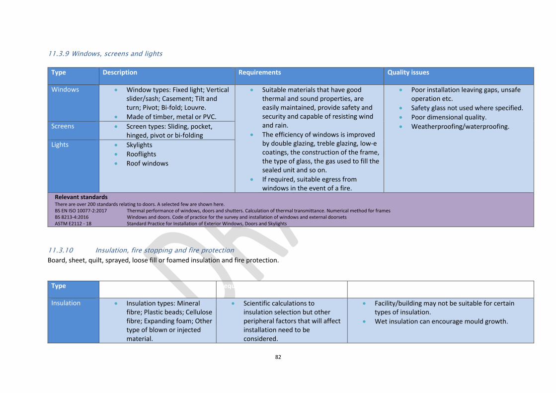
82
11.3.9 Windows, screens and lights
11.3.10 Insulation, fire stopping and fire protection
Board, sheet, quilt, sprayed, loose fill or foamed insulation and fire protection.
Type Description Requirements Quality issues
Windows Window types: Fixed light; Vertical slider/sash; Casement; Tilt and turn; Pivot; Bi-fold; Louvre.
Made of timber, metal or PVC.
Suitable materials that have good thermal and sound properties, are easily maintained, provide safety and security and capable of resisting wind and rain.
The efficiency of windows is improved by double glazing, treble glazing, low-e coatings, the construction of the frame, the type of glass, the gas used to fill the sealed unit and so on.
If required, suitable egress from windows in the event of a fire.
Poor installation leaving gaps, unsafe operation etc.
Safety glass not used where specified.
Poor dimensional quality.
Weatherproofing/waterproofing. Screens Screen types: Sliding, pocket, hinged, pivot or bi-folding
Lights Skylights
Rooflights
Roof windows
Relevant standards There are over 200 standards relating to doors. A selected few are shown here. BS EN ISO 10077-2:2017 Thermal performance of windows, doors and shutters. Calculation of thermal transmittance. Numerical method for frames BS 8213-4:2016 Windows and doors. Code of practice for the survey and installation of windows and external doorsets ASTM E2112 - 18 Standard Practice for Installation of Exterior Windows, Doors and Skylights
Type Description Requirements Quality issues
Insulation Insulation types: Mineral fibre; Plastic beads; Cellulose fibre; Expanding foam; Other type of blown or injected material.
Scientific calculations to insulation selection but other peripheral factors that will affect installation need to be considered.
Facility/building may not be suitable for certain types of insulation.
Wet insulation can encourage mould growth.

83
11.4 Internal finishes
11.4.1 Proprietary linings and partitions
Metal framed systems to walls and ceilings and drylining and partitioning systems to walls and ceilings
Fire stops Fire stop types: Horizontal; Vertical; Raking; Stepped; Curved.
Requirement to adhere to manufacturers’ instructions and general best practice/workmanship.
To recognise that laboratory-based performance tests may not relate well to the installation of insulation on site.
Compliance with and manufacturer’s installation specifications.
Contractor’s skill and experience.
Relevant standards Approved Document Part C Site preparation and resistance to contaminates and moisture ASTM C1859 - 17a Standard Practice for Determination of Thermal Resistance of Loose-Fill Building Insulation in Side Wall Applications. BS 7457:1994 Specification for polyurethane (PUR) foam systems suitable for stabilization and thermal insulation of cavity walls with masonry or concrete inner and outer leaves. BS 7456:1991 Code of practice for stabilization and thermal insulation of cavity walls (with masonry or concrete inner and outer leaves) by filling with polyurethane (PUR) foam systems. BS 5617:1985 Specification for urea-formaldehyde (UF) foam systems suitable for thermal insulation of cavity walls with masonry or concrete inner and outer leaves. BS 5618:1985 Code of practice for thermal insulation of cavity walls (with masonry or concrete inner and outer leaves) by filling with urea-formaldehyde (UF) foam systems. BS ISO 17738-1:2017 Thermal insulation products. Exterior insulation and finish systems. Materials and systems BS EN ISO 10140-1:2016 Acoustics. Laboratory measurement of sound insulation of building elements. Application rules for specific products BS EN 14064-1:2010 Thermal insulation products for buildings. In-situ formed loose-fill mineral wool (MW) products. Specification for the loose-fill products before installation BS EN 14316-2:2007 Thermal insulation products for buildings. In-situ thermal insulation formed from expanded perlite (EP) products. Specification for the installed products BS EN 14317-2:2007 Thermal insulation products for buildings. In-situ thermal insulation formed from exfoliated vermiculite (EV) products. Specification for the installed products BS EN 14317-1:2004 Thermal insulation products for buildings. In-situ thermal insulation formed from exfoliated vermiculite (EV) products. Specification for bonded and loose-fill products before installation BS EN 13499:2003 Thermal insulation products for buildings. External thermal insulation composite systems (ETICS) based on expanded polystyrene. Specification. BS EN 13500:2003 Thermal insulation products for buildings. External thermal insulation composite systems (ETICS) based on mineral wool. Specification. BS EN 14318-1:2013 Thermal insulating products for buildings. In-situ formed dispensed rigid polyurethane (PUR) and polyisocyanurate (PIR) foam products. Specification for the rigid foam dispensed system before installation BS EN 14315-1:2013 Thermal insulating products for buildings. In-situ formed sprayed rigid polyurethane (PUR) and polyisocyanurate (PIR) foam products. Specification for the rigid foam spray system before installation
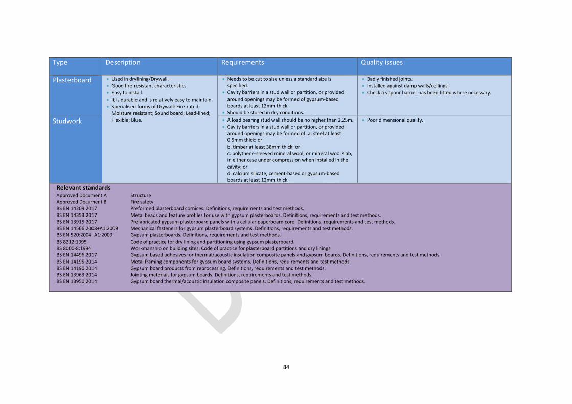
84
Type Description Requirements Quality issues
Plasterboard Used in drylining/Drywall.
Good fire-resistant characteristics.
Easy to install.
It is durable and is relatively easy to maintain.
Specialised forms of Drywall: Fire-rated; Moisture resistant; Sound board; Lead-lined; Flexible; Blue.
Needs to be cut to size unless a standard size is specified.
Cavity barriers in a stud wall or partition, or provided around openings may be formed of gypsum-based boards at least 12mm thick.
Should be stored in dry conditions.
Badly finished joints.
Installed against damp walls/ceilings.
Check a vapour barrier has been fitted where necessary.
Studwork A load bearing stud wall should be no higher than 2.25m.
Cavity barriers in a stud wall or partition, or provided around openings may be formed of: a. steel at least 0.5mm thick; or b. timber at least 38mm thick; or c. polythene-sleeved mineral wool, or mineral wool slab, in either case under compression when installed in the cavity; or d. calcium silicate, cement-based or gypsum-based boards at least 12mm thick.
Poor dimensional quality.
Relevant standards Approved Document A Structure Approved Document B Fire safety BS EN 14209:2017 Preformed plasterboard cornices. Definitions, requirements and test methods. BS EN 14353:2017 Metal beads and feature profiles for use with gypsum plasterboards. Definitions, requirements and test methods. BS EN 13915:2017 Prefabricated gypsum plasterboard panels with a cellular paperboard core. Definitions, requirements and test methods. BS EN 14566:2008+A1:2009 Mechanical fasteners for gypsum plasterboard systems. Definitions, requirements and test methods. BS EN 520:2004+A1:2009 Gypsum plasterboards. Definitions, requirements and test methods. BS 8212:1995 Code of practice for dry lining and partitioning using gypsum plasterboard. BS 8000-8:1994 Workmanship on building sites. Code of practice for plasterboard partitions and dry linings BS EN 14496:2017 Gypsum based adhesives for thermal/acoustic insulation composite panels and gypsum boards. Definitions, requirements and test methods. BS EN 14195:2014 Metal framing components for gypsum board systems. Definitions, requirements and test methods. BS EN 14190:2014 Gypsum board products from reprocessing. Definitions, requirements and test methods. BS EN 13963:2014 Jointing materials for gypsum boards. Definitions, requirements and test methods. BS EN 13950:2014 Gypsum board thermal/acoustic insulation composite panels. Definitions, requirements and test methods.
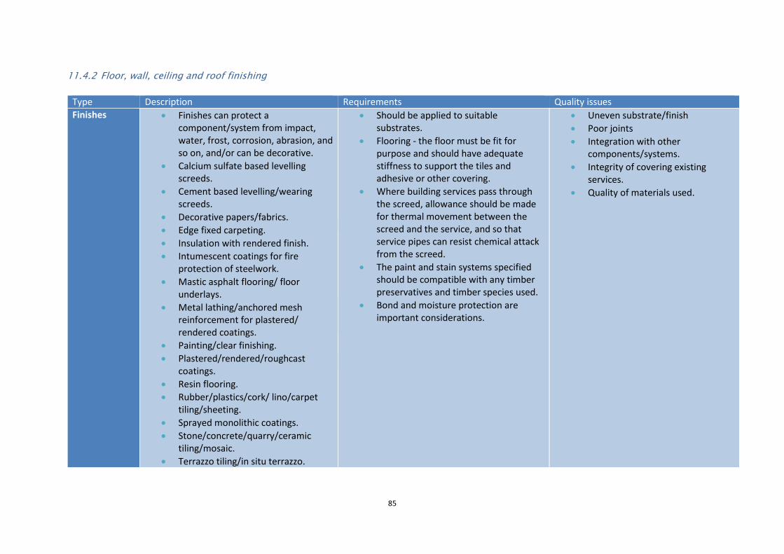
85
11.4.2 Floor, wall, ceiling and roof finishing
Type Description Requirements Quality issues
Finishes Finishes can protect a component/system from impact, water, frost, corrosion, abrasion, and so on, and/or can be decorative.
Calcium sulfate based levelling screeds.
Cement based levelling/wearing screeds.
Decorative papers/fabrics.
Edge fixed carpeting.
Insulation with rendered finish.
Intumescent coatings for fire protection of steelwork.
Mastic asphalt flooring/ floor underlays.
Metal lathing/anchored mesh reinforcement for plastered/ rendered coatings.
Painting/clear finishing.
Plastered/rendered/roughcast coatings.
Resin flooring.
Rubber/plastics/cork/ lino/carpet tiling/sheeting.
Sprayed monolithic coatings.
Stone/concrete/quarry/ceramic tiling/mosaic.
Terrazzo tiling/in situ terrazzo.
Should be applied to suitable substrates.
Flooring - the floor must be fit for purpose and should have adequate stiffness to support the tiles and adhesive or other covering.
Where building services pass through the screed, allowance should be made for thermal movement between the screed and the service, and so that service pipes can resist chemical attack from the screed.
The paint and stain systems specified should be compatible with any timber preservatives and timber species used.
Bond and moisture protection are important considerations.
Uneven substrate/finish
Poor joints
Integration with other components/systems.
Integrity of covering existing services.
Quality of materials used.

86
11.4.3 Suspended ceilings
Wood block/composition block/mosaic parquet flooring.
Relevant standards NHBC Standards Part 8 Services and internal finishing ASTM C1516 - 05(2017) Standard Practice for Application of Direct-Applied Exterior Finish Systems. BS EN 15286:2013 Agglomerated stone. Slabs and tiles for wall finishes (internal and external). ASTM C1528/C1528M - 18 Standard Guide for Selection of Dimension Stone. ASTM F2419 - 11(2017) Standard Practice for Installation of Thick Poured Gypsum Concrete Underlayments and Preparation of the Surface for Resilient Flooring. ASTM E2404 - 17 Standard Practice for Specimen Preparation and Mounting of Textile, Paper or Polymeric (Including Vinyl) and Wood Wall or Ceiling Coverings, Facings and Veneers, to Assess Surface
Burning Characteristics. ASTM C1288 - 17 Standard Specification for Fiber-Cement Interior Substrate Sheets. BS 8203:2017 Code of practice for installation of resilient floor coverings. PD CEN/TR 17024:2017 Natural stones. Guidance for use of natural stones. BS EN 13914-1:2016 Design, preparation and application of external rendering and internal plastering. External rendering BS EN 1468:2012 Natural stone. Rough slabs. Requirements. BS EN 15388:2008 Agglomerated stone. Slabs and cut-to-size products for vanity and kitchen tops. BS 8481:2006 Design, preparation and application of internal gypsum, cement, cement and lime plastering systems. Specification. BS 6150:2006+A1:2014 Painting of buildings. Code of practice. BS 8204-4:2004+A1:2011 Screeds, bases and in situ floorings. Cementitious terrazzo wearing surfaces. Code of practice BS 8204-5:2004+A1:2011 Screeds, bases and in situ floorings. Mastic asphalt underlays and wearing surfaces. Code of practice BS 8425:2003 Code of practice for installation of laminate floor coverings. BS EN 235:2002 Wallcoverings. Vocabulary and symbols. BS 5325:2001 Installation of textile floor coverings. Code of practice. BS EN 259-1:2001 Wallcoverings in roll form. Heavy duty wallcoverings. Specifications BS EN 259-2:2001 Wallcoverings in roll form. Heavy duty wallcoverings. Determination of impact resistance BS EN 12781:2001 Wallcoverings. Specification for cork panels. BS EN 13085:2001 Wallcoverings. Specification for cork rolls. BS EN 12956:1999 Wallcoverings in roll form. Determination of dimensions, straightness, spongeability and washability. BS EN 12149:1998 Wallcoverings in roll form. Determination of migration of heavy metals and certain other elements, of vinyl chloride monomer and of formaldehyde release. BS EN 234:1997 Wallcoverings in roll form. Specification for wallcoverings for subsequent decoration. BS EN 266:1992 Specification for textile wallcoverings.
Type Description Requirements Quality issues
Suspended ceiling (or dropped ceiling)
A suspended ceiling can provide a clean, smooth finish to the internal ceiling of a room, whilst hiding electrical wires, pipework and other services.
Need to be carefully designed in order to integrate with partition systems; tiles, grids and partitions should intersect neatly.
Integration with other components/systems.
Integrity of covering existing services.

87
Suspended ceilings are hung from a bracket fixed to the underside of the floor slab supporting a series of interlocking metal sections that form a grid into which panels such as ceiling tiles can be fitted.
Beam systems are also available, in which tiles are laid between parallel beams rather than a grid, and there are a wide range of different grid profiles and tile edge details that can be used to allow the grid to be exposed, flush, recessed or concealed.
A suspended ceiling can contribute to the overall fire resistance of a floor/ceiling assembly.
Acoustic-absorbing materials can be used.
The void can also be used as an air ‘plenum’, in which the void itself forms a pressurised ‘duct’ to supply air or extract it from the occupied space below.
Partitions may stop at the underside of the suspended ceiling to provide maximum ease of installation and flexibility, or may run through the ceiling to the underside of the floor slab.
Where partitions do not run through the ceiling void, care must be taken to ensure that a flanking path is not created for the transmission of sound between adjacent spaces or for the spread of fire.
Acoustic insulation or fire separation can be provided in the ceiling void if necessary.
Quality of materials used.
Relevant standards ASTM C1858 - 17a Standard Practice for Design, Construction, and Material Requirements for Direct Hung Suspended T-bar Type Ceiling Systems Intended to Receive Gypsum Panel Products in Areas
Subject to Earthquake Ground Motions. BS EN 14246:2006 Gypsum elements for suspended ceilings. Definitions, requirements and test methods. ASTM E580/E580M - 17 Standard Practice for Installation of Ceiling Suspension Systems for Acoustical Tile and Lay-in Panels in Areas Subject to Earthquake Ground Motions. ASTM C754 - 18 Standard Specification for Installation of Steel Framing Members to Receive Screw-Attached Gypsum Panel Products. BS EN ISO 10848-2:2017 Acoustics. Laboratory and field measurement of flanking transmission for airborne, impact and building service equipment sound between adjoining rooms. Application to Type B
elements when the junction has a small influence
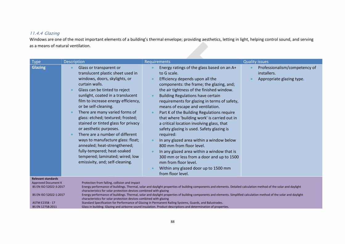
88
11.4.4 Glazing
Windows are one of the most important elements of a building’s thermal envelope; providing aesthetics, letting in light, helping control sound, and serving
as a means of natural ventilation.
Type Description Requirements Quality issues
Glazing Glass or transparent or translucent plastic sheet used in windows, doors, skylights, or curtain walls.
Glass can be tinted to reject sunlight, coated in a translucent film to increase energy efficiency, or be self-cleaning.
There are many varied forms of glass: etched; textured; frosted; stained or tinted glass for privacy or aesthetic purposes.
There are a number of different ways to manufacture glass: float; annealed; heat-strengthened; fully-tempered; heat-soaked tempered; laminated; wired; low emissivity, and; self-cleaning.
Energy ratings of the glass based on an A+ to G scale.
Efficiency depends upon all the components: the frame; the glazing, and; the air tightness of the finished window.
Building Regulations have certain requirements for glazing in terms of safety, means of escape and ventilation.
Part K of the Building Regulations require that where 'building work' is carried out in a critical location involving glass, that safety glazing is used. Safety glazing is required:
In any glazed area within a window below 800 mm from floor level.
In any glazed area within a window that is 300 mm or less from a door and up to 1500 mm from floor level.
Within any glazed door up to 1500 mm from floor level.
Professionalism/competency of installers.
Appropriate glazing type.
Relevant standards Approved Document K Protection from falling, collision and impact BS EN ISO 52022-3:2017 Energy performance of buildings. Thermal, solar and daylight properties of building components and elements. Detailed calculation method of the solar and daylight
characteristics for solar protection devices combined with glazing BS EN ISO 52022-1:2017 Energy performance of buildings. Thermal, solar and daylight properties of building components and elements. Simplified calculation method of the solar and daylight
characteristics for solar protection devices combined with glazing ASTM E2358 - 17 Standard Specification for Performance of Glazing in Permanent Railing Systems, Guards, and Balustrades. BS EN 12758:2011 Glass in building. Glazing and airborne sound insulation. Product descriptions and determination of properties.

89
11.5 Fittings, furnishings and equipment
BS EN 15269-20:2009 Extended application of test results for fire resistance and/ or smoke control for door, shutter and openable window assemblies, including their elements of building hardware. Smoke control for hinged and pivoted steel, timber and metal framed glazed doorsets
BS 5516-1:2004 Patent glazing and sloping glazing for buildings. Code of practice for design and installation of sloping and vertical patent glazing BS 5516-2:2004 Patent glazing and sloping glazing for buildings. Code of practice for sloping glazing BS 8000-7:1990 Workmanship on building sites. Code of practice for glazing BS EN 1279-2:2018 Glass in building. Insulating glass units. Long term test method and requirements for moisture penetration BS EN ISO 10077-2:2017 Thermal performance of windows, doors and shutters. Calculation of thermal transmittance. Numerical method for frames BS EN ISO 12631:2017 Thermal performance of curtain walling. Calculation of thermal transmittance. BS EN ISO 10077-1:2017 Thermal performance of windows, doors and shutters. Calculation of thermal transmittance. General BS EN 1634-1:2014+A1:2018 Fire resistance and smoke control tests for door and shutter assemblies, openable windows and elements of building hardware. Fire resistance test for door and shutter
assemblies and openable windows BS ISO 18292:2011 Energy performance of fenestration systems for residential buildings. Calculation procedure. BS 6375-3:2009+A1:2013 Performance of windows and doors. Classification for additional performance characteristics and guidance on selection and specification BS 7412:2007 Specification for windows and doorsets made from unplasticized polyvinyl chloride (PVC-U) extruded hollow profiles. BS EN ISO 12567-2:2005 Thermal performance of windows and doors. Determination of thermal transmittance by hot box method. Roof windows and other projecting windows BS 8213-1:2004 Windows doors and rooflights. Design for safety in use and during cleaning of windows, including door-height windows and roof windows. Code of practice BS EN ISO 14438:2002 Glass in building. Determination of energy balance value. Calculation method. BS EN 12898:2001 Glass in building. Determination of the emissivity. BS 6206:1981 Specification for impact performance requirements for flat safety glass and safety plastics for use in buildings.
Type Description Requirements Quality issues
Fittings, Furnishings and Equipment (FFE)
The procurement of furniture, fixtures and equipment
These might be procured separately to the main construction contract (or elements of them), especially by clients with procurement systems in place for procuring FFE, e.g. schools, universities, or hospitals.
A fixture is defined as an asset that is installed or otherwise fixed in or to a
The building work or any services required for FFE needs to be identified in the contract. For example, fume cupboards or drinks stations that require M&E connections; built-in equipment not requiring services; stand-alone FFE that require power, air, water, drainage or telecommunication connections; stand-alone FFE that do not require services.
Programming and planning of the FFE procurement and installation is important.
Adequate maintenance plan in place.
Contractor’s skill and experience.
Quality of materials. M&E parts of the installation need to meet safety and
quality standards.
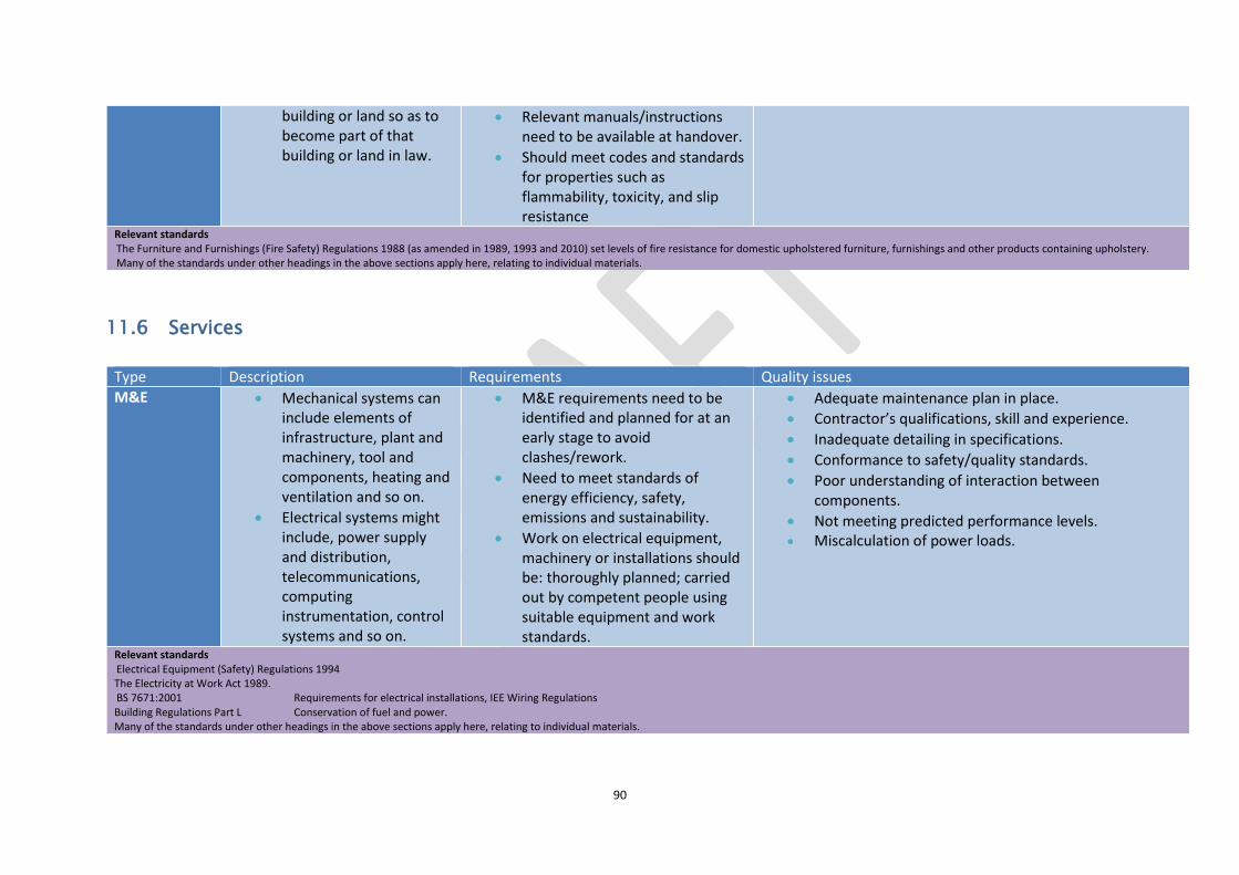
90
11.6 Services
building or land so as to become part of that building or land in law.
Relevant manuals/instructions need to be available at handover.
Should meet codes and standards for properties such as flammability, toxicity, and slip resistance
Relevant standards The Furniture and Furnishings (Fire Safety) Regulations 1988 (as amended in 1989, 1993 and 2010) set levels of fire resistance for domestic upholstered furniture, furnishings and other products containing upholstery. Many of the standards under other headings in the above sections apply here, relating to individual materials.
Type Description Requirements Quality issues
M&E Mechanical systems can include elements of infrastructure, plant and machinery, tool and components, heating and ventilation and so on.
Electrical systems might include, power supply and distribution, telecommunications, computing instrumentation, control systems and so on.
M&E requirements need to be identified and planned for at an early stage to avoid clashes/rework.
Need to meet standards of energy efficiency, safety, emissions and sustainability.
Work on electrical equipment, machinery or installations should be: thoroughly planned; carried out by competent people using suitable equipment and work standards.
Adequate maintenance plan in place.
Contractor’s qualifications, skill and experience.
Inadequate detailing in specifications.
Conformance to safety/quality standards.
Poor understanding of interaction between components.
Not meeting predicted performance levels. Miscalculation of power loads.
Relevant standards Electrical Equipment (Safety) Regulations 1994 The Electricity at Work Act 1989. BS 7671:2001 Requirements for electrical installations, IEE Wiring Regulations Building Regulations Part L Conservation of fuel and power. Many of the standards under other headings in the above sections apply here, relating to individual materials.
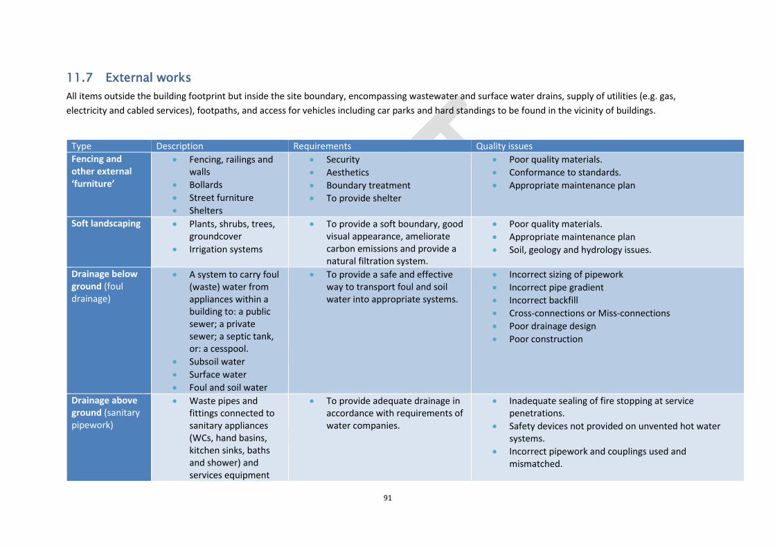
91
11.7 External works
All items outside the building footprint but inside the site boundary, encompassing wastewater and surface water drains, supply of utilities (e.g. gas,
electricity and cabled services), footpaths, and access for vehicles including car parks and hard standings to be found in the vicinity of buildings.
Type Description Requirements Quality issues
Fencing and other external ‘furniture’
Fencing, railings and walls
Bollards
Street furniture
Shelters
Security
Aesthetics
Boundary treatment
To provide shelter
Poor quality materials.
Conformance to standards.
Appropriate maintenance plan
Soft landscaping Plants, shrubs, trees, groundcover
Irrigation systems
To provide a soft boundary, good visual appearance, ameliorate carbon emissions and provide a natural filtration system.
Poor quality materials.
Appropriate maintenance plan
Soil, geology and hydrology issues.
Drainage below ground (foul drainage)
A system to carry foul (waste) water from appliances within a building to: a public sewer; a private sewer; a septic tank, or: a cesspool.
Subsoil water
Surface water
Foul and soil water
To provide a safe and effective way to transport foul and soil water into appropriate systems.
Incorrect sizing of pipework
Incorrect pipe gradient
Incorrect backfill
Cross-connections or Miss-connections
Poor drainage design
Poor construction
Drainage above ground (sanitary pipework)
Waste pipes and fittings connected to sanitary appliances (WCs, hand basins, kitchen sinks, baths and shower) and services equipment
To provide adequate drainage in accordance with requirements of water companies.
Inadequate sealing of fire stopping at service penetrations.
Safety devices not provided on unvented hot water systems.
Incorrect pipework and couplings used and mismatched.

92
(dishwashers and industrial washing machines).
Lack of support throughout the full height of the soil stack.
Vertical stacks terminating into 92 junctions
Pipework connections into soil stacks
Opposed connections into the base of soil stacks
Inadequate falls to horizontal pipework.
Missing sound insulation to pipework.
Site works Roads, paths, pavings and surfacings.
To provide safe and appropriate works for workers, pedestrians and vehicles.
Cycle routes.
Sightlines, radii, gradients to meet standards.
Access for emergency services.
Dropped kerbs, tactile paving and facilities at signalled controlled crossings, lighting, signage as detailed in the Disability Rights Commission’s Code of Practice - 'Rights of Access: Good, Facilities, Services and Premises’.
Uneven surfaces
Poor/lack of maintenance plan.
Poor programme planning leading to untimely construction of road systems
Relevant standards Approved Document H Drainage and waste disposal There are a huge number of relevant standards, for example just the paving-related ones are numerous: BS EN 1338 Concrete Paving Blocks BS EN 1339 Concrete Paving Flags BS EN 1340 Concrete Kerb Units BS EN 1341 Natural Stone Flag Paving BS EN 1342 Natural Stone Setts BS EN 1343 Natural Stone Kerbs BS EN 1344 Clay Pavers BS 7533-1:2001 Guide for the structural design of heavy duty pavements constructed of clay or concrete pavers BS 7533-2:2001 Guide for the structural design of lightly trafficked pavements BS 7533-3:2005+A1:2009 Code of practice for laying precast concrete paving blocks and clay pavers for flexible pavements BS 7533-4:2006 Code of practice for the construction of pavements of precast concrete flags or natural stone slabs BS 7533-6:1999 Code of practice for laying natural stone, precast concrete and clay kerb units

93
BS 7533-7:2010 Code of practice for the construction of pavements of natural stone paving units and cobbles, and rigid construction with concrete block paving BS 7533-8:2003 Guide for the structural design of lightly trafficked pavements of precast concrete flags and natural stone slabs BS 7533-9:2010 Code of practice for the construction of rigid pavements of clay pavers BS 7533-10:2010 Guide for the structural design of trafficked pavements constructed of natural stone setts and bound construction with concrete paving blocks BS 7533-11:2003 Code of practice for the opening, maintenance and reinstatement of pavements of concrete, clay and natural stone. BS 7533-12:2006 Guide to the structural design of trafficked pavements constructed on a bound base using concrete paving flags and natural stone slabs BS 7533-13:2009 Guide for the design of permeable pavements constructed with concrete paving blocks and flags, natural stone slabs and setts and clay pavers

94
12 Appendix One Standards relating to masonry
ASTM C476 - 18 Standard Specification for Grout for Masonry.
ASTM C91/C91M - 18 Standard Specification for Masonry Cement.
ASTM C1660 - 10(2018) Standard Specification for Thin-bed Mortar for Autoclaved Aerated Concrete (AAC) Masonry.
ASTM C140/C140M - 17b Standard Test Methods for Sampling and Testing Concrete Masonry Units and Related Units.
ASTM C144 - 17 Standard Specification for Aggregate for Masonry Mortar.
ASTM C404 - 11(2017) Standard Specification for Aggregates for Masonry Grout.
ASTM C1691 - 11(2017) Standard Specification for Unreinforced Autoclaved Aerated Concrete (AAC) Masonry Units.
ASTM C1384 - 17 Standard Specification for Admixtures for Masonry Mortars.
ASTM C62 - 17 Standard Specification for Building Brick (Solid Masonry Units Made From Clay or Shale).
ASTM C652 - 17a Standard Specification for Hollow Brick (Hollow Masonry Units Made From Clay or Shale).
ASTM C216 - 17a Standard Specification for Facing Brick (Solid Masonry Units Made from Clay or Shale).
ASTM E3121/E3121M - 17 Standard Test Methods for Field Testing of Anchors in Concrete or Masonry.
ASTM C1623 - 17a Standard Specification for Manufactured Concrete Masonry Lintels.
ASTM C1670/C1670M - 17 Standard Specification for Adhered Manufactured Stone Masonry Veneer Units.
ASTM C331/C331M - 17 Standard Specification for Lightweight Aggregates for Concrete Masonry Units.
ASTM C1400 - 11(2017) Standard Guide for Reduction of Efflorescence Potential in New Masonry Walls.
ASTM C279 - 17 Standard Specification for Chemical-Resistant Masonry Units.
ASTM C1780 - 17 Standard Practice for Installation Methods for Adhered Manufactured Stone Masonry Veneer.
ASTM C129 - 17 Standard Specification for Nonloadbearing Concrete Masonry Units.
ASTM C1713 - 17 Standard Specification for Mortars for the Repair of Historic Masonry.
ASTM C139 - 17 Standard Specification for Concrete Masonry Units for Construction of Catch Basins and Manholes.
ASTM C780 - 17 Standard Test Method for Preconstruction and Construction Evaluation of Mortars for Plain and Reinforced Unit Masonry.
ASTM E3069 - 17 Standard Guide for Evaluation and Rehabilitation of Mass Masonry Walls for Changes to Thermal and Moisture Properties of the Wall.
BS EN 998-1:2016 Specification for mortar for masonry. Rendering and plastering mortar
BS EN 998-2:2016 Specification for mortar for masonry. Masonry mortar
BS EN 1015-12:2016 Methods of test for mortar for masonry. Determination of adhesive strength of hardened rendering and plastering mortars on substrates
BS EN 1052-2:2016 Methods of test for masonry. Determination of flexural strength
BS EN 772-5:2016 Methods of test for masonry units. Determination of the active soluble salts content of clay masonry units
ASTM A951/A951M - 16e1 Standard Specification for Steel Wire for Masonry Joint Reinforcement.
ASTM C1713 - 15 Standard Specification for Mortars for the Repair of Historic Masonry.
BS EN 16572:2015 Conservation of cultural heritage. Glossary of technical terms concerning mortars for masonry, renders and plasters used in cultural heritage.
BS 8103-2:2013 Structural design of low-rise buildings. Code of practice for masonry walls for housing
BS EN 845-1:2013+A1:2016 Specification for ancillary components for masonry. Wall ties, tension straps, hangers and brackets
BS EN 845-2:2013+A1:2016 Specification for ancillary components for masonry. Lintels
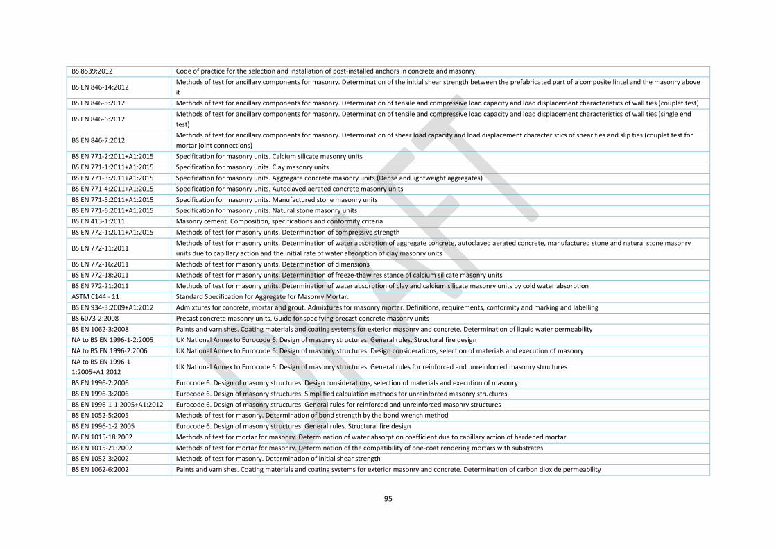
95
BS 8539:2012 Code of practice for the selection and installation of post-installed anchors in concrete and masonry.
BS EN 846-14:2012 Methods of test for ancillary components for masonry. Determination of the initial shear strength between the prefabricated part of a composite lintel and the masonry above
it
BS EN 846-5:2012 Methods of test for ancillary components for masonry. Determination of tensile and compressive load capacity and load displacement characteristics of wall ties (couplet test)
BS EN 846-6:2012 Methods of test for ancillary components for masonry. Determination of tensile and compressive load capacity and load displacement characteristics of wall ties (single end
test)
BS EN 846-7:2012 Methods of test for ancillary components for masonry. Determination of shear load capacity and load displacement characteristics of shear ties and slip ties (couplet test for
mortar joint connections)
BS EN 771-2:2011+A1:2015 Specification for masonry units. Calcium silicate masonry units
BS EN 771-1:2011+A1:2015 Specification for masonry units. Clay masonry units
BS EN 771-3:2011+A1:2015 Specification for masonry units. Aggregate concrete masonry units (Dense and lightweight aggregates)
BS EN 771-4:2011+A1:2015 Specification for masonry units. Autoclaved aerated concrete masonry units
BS EN 771-5:2011+A1:2015 Specification for masonry units. Manufactured stone masonry units
BS EN 771-6:2011+A1:2015 Specification for masonry units. Natural stone masonry units
BS EN 413-1:2011 Masonry cement. Composition, specifications and conformity criteria
BS EN 772-1:2011+A1:2015 Methods of test for masonry units. Determination of compressive strength
BS EN 772-11:2011 Methods of test for masonry units. Determination of water absorption of aggregate concrete, autoclaved aerated concrete, manufactured stone and natural stone masonry
units due to capillary action and the initial rate of water absorption of clay masonry units
BS EN 772-16:2011 Methods of test for masonry units. Determination of dimensions
BS EN 772-18:2011 Methods of test for masonry units. Determination of freeze-thaw resistance of calcium silicate masonry units
BS EN 772-21:2011 Methods of test for masonry units. Determination of water absorption of clay and calcium silicate masonry units by cold water absorption
ASTM C144 - 11 Standard Specification for Aggregate for Masonry Mortar.
BS EN 934-3:2009+A1:2012 Admixtures for concrete, mortar and grout. Admixtures for masonry mortar. Definitions, requirements, conformity and marking and labelling
BS 6073-2:2008 Precast concrete masonry units. Guide for specifying precast concrete masonry units
BS EN 1062-3:2008 Paints and varnishes. Coating materials and coating systems for exterior masonry and concrete. Determination of liquid water permeability
NA to BS EN 1996-1-2:2005 UK National Annex to Eurocode 6. Design of masonry structures. General rules. Structural fire design
NA to BS EN 1996-2:2006 UK National Annex to Eurocode 6. Design of masonry structures. Design considerations, selection of materials and execution of masonry
NA to BS EN 1996-1-
1:2005+A1:2012 UK National Annex to Eurocode 6. Design of masonry structures. General rules for reinforced and unreinforced masonry structures
BS EN 1996-2:2006 Eurocode 6. Design of masonry structures. Design considerations, selection of materials and execution of masonry
BS EN 1996-3:2006 Eurocode 6. Design of masonry structures. Simplified calculation methods for unreinforced masonry structures
BS EN 1996-1-1:2005+A1:2012 Eurocode 6. Design of masonry structures. General rules for reinforced and unreinforced masonry structures
BS EN 1052-5:2005 Methods of test for masonry. Determination of bond strength by the bond wrench method
BS EN 1996-1-2:2005 Eurocode 6. Design of masonry structures. General rules. Structural fire design
BS EN 1015-18:2002 Methods of test for mortar for masonry. Determination of water absorption coefficient due to capillary action of hardened mortar
BS EN 1015-21:2002 Methods of test for mortar for masonry. Determination of the compatibility of one-coat rendering mortars with substrates
BS EN 1052-3:2002 Methods of test for masonry. Determination of initial shear strength
BS EN 1062-6:2002 Paints and varnishes. Coating materials and coating systems for exterior masonry and concrete. Determination of carbon dioxide permeability

96
BS EN 772-14:2002 Methods of test for masonry units. Determination of moisture movement of aggregate concrete and manufactured stone masonry units
BS EN 846-4:2002 Methods of test for ancillary components for masonry. Determination of load capacity and load-deflection characteristics of straps
BS EN 846-13:2001 Methods of test for ancillary components for masonry. Determination of resistance to impact, abrasion and corrosion of organic coatings
BS EN 772-6:2001 Methods of test for masonry units. Determination of bending tensile strength of aggregate concrete masonry units
BS 8000-3:2001 Workmanship on building sites. Code of practice for masonry
BS EN 772-15:2000 Methods of test for masonry units. Determination of water vapour permeability of autoclaved aerated concrete masonry units
BS EN 1015-17:2000 Methods of test for mortar for masonry. Determination of water-soluble chloride content of fresh mortars
BS EN 1052-4:2000 Methods of test for masonry. Determination of shear strength including damp proof course
BS EN 12418:2000+A1:2009 Masonry and stone cutting-off machines for job site. Safety.
BS EN 772-13:2000 Methods of test for masonry units. Determination of net and gross dry density of masonry units (except for natural stone)
BS EN 772-19:2000 Methods of test for masonry units. Determination of moisture expansion of large horizontally perforated clay masonry units
BS EN 772-20:2000 Methods of test for masonry units. Determination of flatness of faces of masonry units
BS EN 846-10:2000 Methods of test for ancillary components for masonry. Determination of load capacity and load deflection characteristics of brackets
BS EN 846-11:2000 Methods of test for ancillary components for masonry. Determination of dimensions and bow of lintels
BS EN 846-2:2000 Methods of test for ancillary components for masonry. Determination of bond strength of prefabricated bed joint reinforcement in mortar joints
BS EN 846-3:2000 Methods of test for ancillary components for masonry. Determination of shear load capacity of welds in prefabricated bed joint reinforcement
BS EN 846-8:2000 Methods of test for ancillary components for masonry. Determination of load capacity and load-deflection characteristics of joist hangers
ISO 9652-5:2000 Masonry. Vocabulary
BS EN 1015-10:1999 Methods of test for mortar for masonry. Determination of dry bulk density of hardened mortar
BS EN 1015-11:1999 Methods of test for mortar for masonry. Determination of flexural and compressive strength of hardened mortar
BS EN 1015-9:1999 Methods of test for mortar for masonry. Determination of workable life and correction time of fresh mortar
BS EN 772-10:1999 Methods of test for masonry units. Determination of moisture content of calcium silicate and autoclaved aerated concrete units
BS EN 1015-3:1999 Methods of test for mortar for masonry. Determination of consistence of fresh mortar (by flow table)
BS EN 1015-1:1999 Methods of test for mortar for masonry. Determination of particle size distribution (by sieve analysis)
BS EN 1015-2:1999 Methods of test for mortar for masonry. Bulk sampling of mortars and preparation of test mortars
BS EN 1015-4:1999 Methods of test for mortar for masonry. Determination of consistence of fresh mortar (by plunger penetration)
BS EN 1015-6:1999 Methods of test for mortar for masonry. Determination of bulk density of fresh mortar
BS EN 1015-7:1999 Methods of test for mortar for masonry. Determination of air content of fresh mortar
BS EN 1052-1:1999 Methods of test for masonry. Determination of compressive strength
BS EN 1015-19:1999 Methods of test for mortar for masonry. Determination of water vapour permeability of hardened rendering and plastering mortars
BS EN 772-2:1998 Methods of test for masonry units. Determination of percentage area of voids in masonry units (by paper indentation)
BS EN 772-3:1998 Methods of test for masonry units. Determination of net volume and percentage of voids of clay masonry units by hydrostatic weighing
BS EN 772-4:1998 Methods of test for masonry units. Determination of real and bulk density and of total and open porosity for natural stone masonry units
BS EN 772-7:1998 Methods of test for masonry units. Determination of water absorption of clay masonry damp proof course units by boiling in water
BS EN 772-9:1998 Methods of test for masonry units. Determination of volume and percentage of voids and net volume of clay and calcium silicate masonry units by sand filling
BS EN 1934:1998 Thermal performance of buildings. Determination of thermal resistance by hot box method using heat flow meter. Masonry.
BS 7457:1994 Specification for polyurethane (PUR) foam systems suitable for stabilization and thermal insulation of cavity walls with masonry or concrete inner and outer leaves.
BS 5080-1:1993 Structural fixings in concrete and masonry. Method of test for tensile loading

97
BS 7456:1991 Code of practice for stabilization and thermal insulation of cavity walls (with masonry or concrete inner and outer leaves) by filling with polyurethane (PUR) foam systems.
BS 8215:1991 Code of practice for design and installation of damp-proof courses in masonry construction.
BS 5080-2:1986 Structural fixings in concrete and masonry. Method for determination of resistance to loading in shear
BS 5617:1985 Specification for urea-formaldehyde (UF) foam systems suitable for thermal insulation of cavity walls with masonry or concrete inner and outer leaves.
BS 5618:1985 Code of practice for thermal insulation of cavity walls (with masonry or concrete inner and outer leaves) by filling with urea-formaldehyde (UF) foam systems.
BS 6515:1984 Specification for polyethylene damp-proof courses for masonry.
BS 6398:1983 Specification for bitumen damp-proof courses for masonry.
ASTM C1019 - 18 Standard Test Method for Sampling and Testing Grout.
ASTM C1586 - 17 Standard Guide for Quality Assurance of Mortars.
ASTM C1088 - 17 Standard Specification for Thin Veneer Brick Units Made From Clay or Shale.
ASTM C1364 - 17 Standard Specification for Architectural Cast Stone.
ASTM C1372 - 17 Standard Specification for Dry-Cast Segmental Retaining Wall Units.
ASTM C1272 - 17 Standard Specification for Heavy Vehicular Paving Brick.
ASTM C212 - 17 Standard Specification for Structural Clay Facing Tile.
ASTM C980 - 17 Standard Specification for Industrial Chimney Lining Brick.
ASTM C55 - 17 Standard Specification for Concrete Building Brick.
ASTM C34 - 17 Standard Specification for Structural Clay Loadbearing Wall Tile.
ASTM C1634 - 17 Standard Specification for Concrete Facing Brick.
ASTM C73 - 17 Standard Specification for Calcium Silicate Brick (Sand-Lime Brick).
BS EN 13914-1:2016 Design, preparation and application of external rendering and internal plastering. External rendering
BS 8002:2015 Code of practice for earth retaining structures.
BS ISO 13033:2013 Bases for design of structures. Loads, forces and other actions. Seismic actions on non-structural components for building applications.
BS EN 14617-1:2013 Agglomerated stone. Test methods. Determination of apparent density and water absorption
BS EN 14617-13:2013 Agglomerated stone. Test methods. Determination of electrical resistivity
BS 8221-1:2012 Code of practice for cleaning and surface repair of buildings. Cleaning of natural stone, brick, terracotta and concrete
BS EN 14617-10:2012 Agglomerated stone. Test methods. Determination of chemical resistance
BS EN 14617-12:2012 Agglomerate stone. Test methods. Determination of dimensional stability
BS EN 14617-4:2012 Agglomerated stone. Test methods. Determination of the abrasion resistance
BS EN 14617-5:2012 Agglomerated stone. Test methods. Determination of freeze and thaw resistance
BS EN 14617-6:2012 Agglomerated stone. Test methods. Determination of thermal shock resistance
BS 8103-1:2011 Structural design of low-rise buildings. Code of practice for stability, site investigation, foundations, precast concrete floors and ground floor slabs for housing
BS 8298-3:2010 Code of practice for the design and installation of natural stone cladding and lining. Stone-faced pre-cast concrete cladding systems
BS EN 1998-3:2005 Eurocode 8. Design of structures for earthquake resistance. Assessment and retrofitting of buildings
BS EN 14617-11:2005 Agglomerated stone. Test methods. Determination of linear thermal expansion coefficient
BS EN 14617-15:2005 Agglomerated stone. Test methods. Determination of compressive strength
BS EN 14617-16:2005 Agglomerated stone. Test methods. Determination of dimensions, geometric characteristics and surface quality of modular tiles
BS EN 14617-9:2005 Agglomerated stone. Test methods. Determination of impact resistance
BS EN 13139:2002 Aggregates for mortar.

98
ISO 15709:2002 Masonry. Part 4: Test methods
BS 8221-2:2000 Code of practice for cleaning and surface repair of buildings. Surface repair of natural stones, brick and terracotta
BS 8298:1994 Code of practice for design and installation of natural stone cladding and lining.
BS 5977-1:1981 Lintels. Method for assessment of load
BS 1199 and 1200:1976 Specifications for building sands from natural sources.