coil antenna design-radio frequency identification systems of antenna matching circuit(4 ohms to 50...
TRANSCRIPT
International Journal of Science and Research (IJSR) ISSN (Online): 2319-7064
Impact Factor (2012): 3.358
Volume 3 Issue 11, November 2014 www.ijsr.net
Licensed Under Creative Commons Attribution CC BY
Coil Antenna Design-Radio Frequency Identification Systems
Shailesh D. Rokade1, Swati U. Kadlag², Dr. Abhay N. Gaikwad3
1Department of Electronics and Tele-Communications, B.N.C.O.E, Pusad: 445215, Maharashtra, India
2Department of Electronics and Tele-Communications, Symbiosis International University, Pune-412115, Maharashtra, India
Abstract: In modern world there are many advancements seen in the Radio Frequency Identification (RFID) technology. Enhancing the usefulness of barcodes, allowing product tracing and the effective usage in chip credit card technology, locating misplaced objects are the current important usages of RFID in the world. There are various modules of the RFID reader are available in the market. But, it is found that, generally the range for low power passive RFID reader is approximately 10cm. In order to increase the range, this paper provides the details of coil antenna as a solution which can be interfaced with the RFID reader operated on 13.56MHz. In this paper, an antenna with relatively small dimensions that is more appropriate for usage, is designed and implemented to achieve one of the important parameter i.e. range of RFID reader. Keywords: RFID, coil antenna, reader, passive 1. Introduction Radio Frequency Identification (RFID) is a technique which automatically identifies the objects. It has seen that this technology has been used in many application areas over last few decades. It has attracted many of researchers or other people to carry out their work in this field over the last few decades. It is found that the first use of RFID was found during World War II in friend or enemy detection system [1]. It is used at various places such as at home for security, in shopping malls for product tracking, at toll plazas for money collection, in lift for access control, in companies for attendance registration [2]-[3]. RFID has become a new and exciting area of technological development, and is receiving increasing amounts of attention. This technology is based on the modulation phenomenon. The radio frequency signal is modulated in order to transfer data between its two important elements that are RFID reader and RFID tags. RFID requires no line of sight for identifying objects which is a very important feature as compared to other identifying technologies [4]. A modulated radio frequency signal is used to transfer data from transponders, attached to people, animals or objects, to a reader in the vicinity [2]. There are various factors on which the range of RFID reader depends but, this paper is focussed on the design of antenna for improving range. This paper introduces a coil antenna design for passive RFID systems. This paper is organised in various sections: section 2 describes about basic blocks of RFID system, section 3 describes about coil antenna, section 4 describes about implementation, section 5 describes about Results and Discussion. 2. RFID System The RFID system mainly consists of three main components: RFID reader, RFID tag and Middleware.
(a) A transponder or tag with a unique identifier that facilitates auto-identification of any object to which the tag is attached. (b) A reader or interrogator that manages the radio frequency communication with the tags. (c) A middleware or reader interface layer, which is essentially a type of software that acts as an interface between the basic RFID hardware components, and the software application tasked with data collection related to tag [5]. Since, RF communication requires the transmission and / or reception of data, the reader, as well as the tag, are in essence RF transceivers that are equipped with suitable antennas [1]. The reader acts as a transmitter in the reader-to-tag communication, which is referred to as the forward link and as a receiver in the tag-to-reader communication is referred to as the back link. The tag communicates by acting in the opposite mode than that of the reader in each of the link directions. Real world RFID implementations indicate substantial variations in the type or form of the fundamental components used, based on application-specific requirements [1],[3].
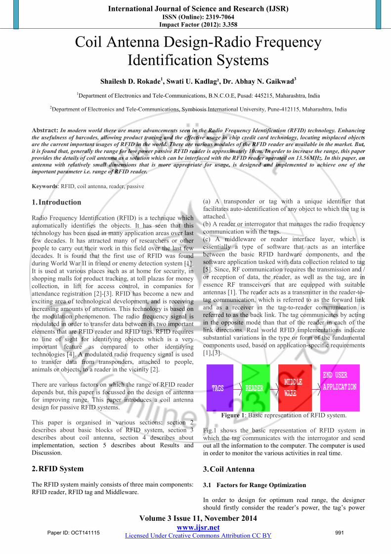
Figure 1: Basic representation of RFID system.
Fig.1 shows the basic representation of RFID system in which the tag communicates with the interrogator and send out all the information to the computer. The computer is used in order to monitor the various activities in real time. 3. Coil Antenna 3.1 Factors for Range Optimization In order to design for optimum read range, the designer should firstly consider the reader’s power, the tag’s power
Paper ID: OCT141115 991
International Journal of Science and Research (IJSR) ISSN (Online): 2319-7064
Impact Factor (2012): 3.358
Volume 3 Issue 11, November 2014 www.ijsr.net
Licensed Under Creative Commons Attribution CC BY
consumption, the tag’s quality factor (Q), the tag’s tuning, the reader’s antenna aperture, and the tag’s antenna aperture [4],[6]. After this the designer on the secondary basis should consider the tag’s modulation depth, the reader’s SNR, the tag’s power-conversion efficiency, the reader’s antenna tuning and carrier accuracy, the reader’s filter quality, how well the reader’s driver matches the antenna, the microcontroller’s speed and code efficiency, and the tag’s data rate [6]. The modulation type also affects read range(ASK,FSK,PSK). Also, the application environment can affect read range [6]. Out of all these factors this paper is focused on the RFID reader antenna design factor for improving the read range. 3.2 Proposed Design RFID works in various frequency bands, but the most widely used frequency band is 13.56 MHz which is in the high frequency (HF) band [7]. Considering the wavelength in this frequency is 22.12 meters in the air and the wavelength is usually proportional with the antenna dimensions, designing small antennas for practical purposes is a challenging problem in the RFID technology [7]-[8]. In order to resolve the above problem and to increase the range of the RFID reader we have designed the coil antenna. The Specifications are listed below:
i. The Type of antenna designed is Coil shaped antenna. ii. The Material of the coil used for the designing the coil
shaped antenna is Copper material. iii. The coil antenna is of square shaped. iv. Dimensions of the antenna is 30cm by 30cm. v. Coil is fixed on the plastic cardboard with a single turn.
vi. The Quality Factor(Q) for this coil shaped antenna is 20. vii. The Coil Inductance is found to be approximately
1.6uH. viii. The Frequency of operation of the antenna is 13.56MHz. 3.3 Inductance Measurement In order to measure the inductance of the coil we have used Logic analyzer and mathematical formulae [4],[9]. The equation(1) below is used to calculate the Inductance of the square shape antenna :
××
×= 379.0+2
414.1008.0Diameter
SideLNsideL Hµ (1)
Here, Side = Centre to centre length of antenna side (cm) Diameter = Tube diameter (cm) 3.4 Measurement of Resonance Capacitance The value of resonant capacitance is calculated by using equation (2) given below:
LCRES 2
1ω
= (2)
Where, ω=2πƒ and ƒ= 13.56MHz
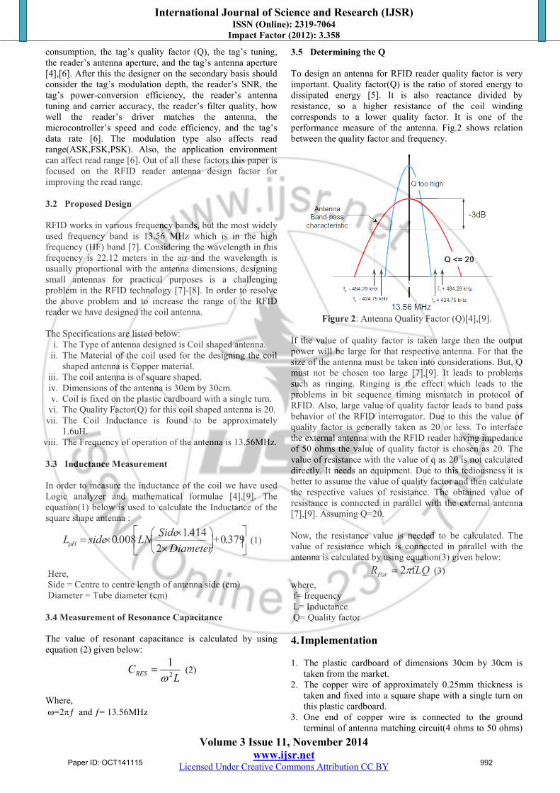
3.5 Determining the Q To design an antenna for RFID reader quality factor is very important. Quality factor(Q) is the ratio of stored energy to dissipated energy [5]. It is also reactance divided by resistance, so a higher resistance of the coil winding corresponds to a lower quality factor. It is one of the performance measure of the antenna. Fig.2 shows relation between the quality factor and frequency.
Figure 2: Antenna Quality Factor (Q)[4],[9].
If the value of quality factor is taken large then the output power will be large for that respective antenna. For that the size of the antenna must be taken into considerations. But, Q must not be chosen too large [7],[9]. It leads to problems such as ringing. Ringing is the effect which leads to the problems in bit sequence timing mismatch in protocol of RFID. Also, large value of quality factor leads to band pass behavior of the RFID interrogator. Due to this the value of quality factor is generally taken as 20 or less. To interface the external antenna with the RFID reader having impedance of 50 ohms the value of quality factor is chosen as 20. The value of resistance with the value of q as 20 is not calculated directly. It needs an equipment. Due to this tediousness it is better to assume the value of quality factor and then calculate the respective values of resistance. The obtained value of resistance is connected in parallel with the external antenna [7],[9]. Assuming Q=20. Now, the resistance value is needed to be calculated. The value of resistance which is connected in parallel with the antenna is calculated by using equation(3) given below:
LQRPar f2π= (3) where, f= frequency L= Inductance Q= Quality factor
4. Implementation 1. The plastic cardboard of dimensions 30cm by 30cm is
taken from the market. 2. The copper wire of approximately 0.25mm thickness is
taken and fixed into a square shape with a single turn on this plastic cardboard.
3. One end of copper wire is connected to the ground terminal of antenna matching circuit(4 ohms to 50 ohms)
Paper ID: OCT141115 992

International Journal of Science and Research (IJSR) ISSN (Online): 2319-7064
Impact Factor (2012): 3.358
Volume 3 Issue 11, November 2014 www.ijsr.net
Licensed Under Creative Commons Attribution CC BY
provided on the RFID reader module. While, the other end of this coil is connected to the antenna tuning circuit as shown in the Fig.5.
4. The range is checked and it found to be increased from approximately 8cm to approximately 18cm. The block schematic of the design is shown in the Fig.3 below:
Figure 3: Interfacing diagram of RFID reader and designed
Coil antenna.
5. Results and Discussion 5.1Before Tuning We have observed the graph of the square shaped antenna on the Agilent technologies E5071C(300KHz-14GHz) ENA series network analyzer. The Fig.4 describes about the result obtained.
Figure 4: Parameters of Antenna before tuning on logic
analyzer. Here, one can see the ‘1’ mark is towards the right side of the curve. It means that the antenna is not showing the proper characteristics and it needs to be tuned for the same frequency. By observing this Fig. 4 and using above mathematical formulae we have calculated the values of the tuning components as below :
Rpar = 2.1K, CRES = 42pf, C = 25pf
We have connected all these components to the coil antenna. The schematic of the tuning circuit is shown in the following Fig.5:
Figure 5: Antenna tuning Circuit.
By interfacing this tuning circuit with the coil antenna and matching circuit the antenna is tuned. 5.2 After Tuning
Figure 6: Parameters of Antenna after tuning with tuning
components on logic analyzer.
After connecting the antenna to the antenna tuning circuit we have found the smooth curve as shown in above Fig.6. The graph shows the fine tuning of antenna on the logic analyzer. We have tested the designed antenna on the RFID reader board and checked with the range. The range achieved is approximately 18 cm. The snapshot of the designed antenna is as shown in the following Fig.7.
Figure 7: Snapshot of the designed external coil Antenna
6. Conclusion In order to increase the range of RFID reader we have designed the coil antenna. This antenna is very useful for increasing the range of RFID reader operated on 13.56MHz
Paper ID: OCT141115 993
International Journal of Science and Research (IJSR) ISSN (Online): 2319-7064
Impact Factor (2012): 3.358
Volume 3 Issue 11, November 2014 www.ijsr.net
Licensed Under Creative Commons Attribution CC BY
having impedance matching circuit of approximately 4 ohms to 50 ohms. The designed antenna is very economical and made up of easily available components. References [1] C‐H. Huang, An Overview of RFID Technology,
Application, and Security/Privacy Threats and Solutions, Scholarly Paper, Spring 2009.
[2] E.W.T. Ngai, K.K.L. Moon, F.J. Riggins, Y. Yi. Candace,” An Academic Literature review (1995-2005) and Future research directions”, International Journal of Production Economics.112, 510-520, 2008.
[3] A. Grover, and H. Berghel, ”A Survey of RFID deployment and security Issues”, Journal of Information processing systems. vol7, No.4,2011.
[4] J. A. Goulbourne, “HF antenna cook book-RFID systems”, technical application report, Northampton, 11-08-26-003,Sept 2003.
[5] C‐H. Huang, An Overview of RFID Technology, Application, and Security/Privacy Threats and Solutions, Scholarly Paper, Spring 2009
[6] P. Sorrells, Optimizing read range in RFID systems design feature, Microchip Technology Inc., December 7, 2000.
[7] Y. Lee, Antenna Circuit Design for RFID Applications AN710, Microchip Technology Inc., DS00710C, 2003.
[8] F. Eken, RFID Receiver Antenna Project for 13.56 MHz Band, TE 401 Microwave Course Term Project, Sabancı University, İstanbul, Fall 2004.
[9] J. Schillinger,” Antenna Matching for the TRF7960 RFID Reader- Application Report”, Texas Instruments, SLOA135A–May 2009–Revised September 2013.
[10] V. Chawla and D. Sam Ha.,”An overview of passive RFID”, IEEE Applications & Practice, September 2007.
Author Profile
Shailesh D. Rokade, has received the B.E. Electronics and Tele-communication from Sant Gadgebaba Amravati university, Amravati May 2011, He has received M.TECH in Electronics & Telecommunication Engineering from Symbiosis International University, Pune June 2014, India. He has
worked in Industry for 1 Year. Currently, he is working as an Assistant Professor at Babasaheb Naik College Of Engineering, Pusad. His research interests includes RFID applications, digital signal processing, VLSI circuits and Embedded system design.
Swati U. Kadlag, Has received the Diploma Electronics from Mumbai University 1999, B .E Electronics from Pune University 2009, M.E Electronics from Shivaji University 2011. She has
Overall 10 years of experience in teaching at degree level in various engineering and Technology Institutes of repute. Served in R&D from Aug 2001-Sep 2002 with Electronic Switches private Ltd, Nasik. Currently, she is Faculty at Symbiosis Institute of Technology, Pune. Her research includes Application of RFID, Image processing applied to toll plaza and check post, Mobile adhoc networks, optical network design.
Dr. Abhay N. Gaikwad, received the B.E and M.Tech degree in Electronics from Baba sahib Naik College of Engg., Pusad and VNIT (formerly VRCE) Nagpur, Maharashtra, India respectively. He received Ph.D
degree in Electronics Engineering from Indian Institute of
Technology, Roorkee, India, in 2012. His area of research includes wireless communication, through wall object detection, signal and image processing. Presently he is working as Professor in department of Electronics and Telecommunication, Babasaheb Naik College of Engineering, Pusad, Maharashtra, India.
Paper ID: OCT141115 994