college of instrumentation & electrical engineering, jilin...
TRANSCRIPT

College of Instrumentation & Electrical Engineering, Jilin University
Academic Practice “Six in One” Training Project
English Proceedings
2015 (Second Half)

I
CONTENTS
Application and Research Design of Numerical Control Voltage Source in Practical Production .......... .............................................................................................. Gan Diyuan; Huang Linshu; Tan Hao 1 Intelligent anti-theft lock racking system ................................................................................................ .................................................................................................. Pang Shuo; Qujian Fu; Miaolan Li 9 Smart Home based on Raspberry Pi ........................................................................................................ ............................................................................................ Liu Jiwei; Liu Mengchen; Gao Ranran 15 Distributed Wirele Monitoring System of Factory Machinery Temperature .......................................... ............................................................................................. Cao zhan-peng; Zhou bo; Mu-tingting 21 The design of semiconductor laser modulation circuit based on DDS technology ................................. ...................................................................................... Jiang yanhui; Sun chaofan; Chen wenxing 27 Life rescue system based on CC1101 ...................................................................................................... .................................................................................................. Gao Jiafei; Deng Wen; Sun Liyuan 35 Design of intelligent guide rod based on the infrared alarm .................................................................... ........................................................................................... XIE Yantong; CUI Yuqi; DENG Qitian 41 Design and implementation of a movement monitoring system based on the human body sensor and android technology ................................................................................................................................... ................................................................................................. Caijing; Zhourui; Tianruyun; Liulei 45 Design and implementation of speech presenter microphone based on LD3320 .................................... ....................................................................................... Liang Yi-gang; Huang Ji-wei; Liu Shi-bin 51 Portable positioning device for field wiring of electromagnetic field ..................................................... .......................................................................................... Wang Haoyu; Zhang Caihong; Ren Wei 57 Design and Implementation of Micro-quality PVDF-based Weighing System ....................................... .......................................................................................................... Peng Cong; Liu Bo; Yan Jiaqi 63 The research and design of the single oil well tank of information monitoring and control system ....... .................................................................................. Cai Jing; Wang Qian; Yang Yujing; Li Chang 67 The design of bluetooth entrance control system .................................................................................... ................................................................................................. Qi Wang; Chao Yang; Yiguang Bao 71 Ultrasonic Ranging Based on blind navigation Headphones ................................................................... ................................................................................... Xiaotong Cui; Zhaofeng Zhang;Xulei Wang 77 The design of a tracing luggage robot based on the ultrasonic ranging ................................................... ......................................................................................... Ning Hong-yang; Wang Ti-kuo; Zhao Yi 81

Gan Diyuan etc.: Application and Research Design of Numerical Control Voltage Source in Practical Production
1
Application and Research Design of Numerical Control Voltage Source in Practical Production
Gan Diyuan; Huang Linshu; Tan Hao
(College of Instrumentation and Electrical Engineering, Jilin University Changchun 130026)
Abstract-With the rapid development of science and technology, power technology has increasingly become a practical and
comprehensive engineering technology, widely used in all walks of life, and the numerical control power supply technology is
particularly important. .Microsecond, pulse type numerical control voltage source is controlled by the size of the digital
output voltage. The output pulse voltage amplitude, pulse width, frequency can be adjusted. This paper studies the
development of numerical control voltage source, introduces the design and implementation of the micro - level, pulse type
numerical control voltage source,.The digital control technology of single chip microcomputer is integrated into the design of
voltage source, reasonably and effectively .It makes the control of the power supply is more simple and implementation of the
power supply of CNC.
Key words-Numerical control; ATmega16 single chip microcomputer; D/A conversion; A/D conversion
INTRODUCTION
ALONG with the development of science and technology, the modern information technology has provided a more broad development platform for the development of power electronics technology, at the same time, the power supply technology has been put forward more stringent standards and requirements. Power supply is a very important part of the electronic equipment, the traditional power in the work of the error, will have a considerable impact on the accuracy of the whole system, this is a more stringent requirements on the numerical control voltage source. Numerical control voltage source is one of the equipments which is often used in the electronic technology nowadays, and it is widely used in various industries.
The traditional voltage source is usually the band switch and potentiometer to adjust the voltage source, the voltage value of the voltage meter to indicate the size of the voltage value, so that the reading accuracy is not high, and easy to wear. Compared with the traditional voltage source, the numerical control voltage source based on single chip microcomputer control has the characteristics of easy control, high reliability and high accuracy. It is a good solution to the problem of the traditional voltage source.
From the first generation of the 80's in the last century, the first generation of distributed power
supply system has been to the beginning of twenty-first Century, more advanced fourth generation distributed power supply structure, the power industry is facing a new challenge, that is, the existing system in the embedded power supply digital control and intelligent systems. The numerical control voltage source is from the last century 80 's only then truly starts to develop. During this period, the entire system of power electronics theory began to gradually establish and continuously improve, in a long time, the numerical control voltage source technology has a long-term development; in the 90's, semiconductor manufacturers to develop a numerical control voltage source management technology, but at that time, this technology has been used in a wide range of simulation control scheme, which is in a inferior position, so this technology can not be widely used.
The research on the numerical control voltage source in China started late, and in the late ninety's of the last century, under the National Natural Science Foundation of China, Zhejiang University, North China Electric Power University and other colleges and universities have launched this aspect of the basic theoretical research.
Numerical control power supply technology has been developed from 1980s to now, but its products still exist in this way or that, such as its high resolution, low reliability, etc.. It can be seen that the development direction of the numerical
The English Proceedings of the College of Instrumentation & Electrical Engineering, Jilin University, in the Second Half of 2015
2
control power supply is mainly to improve the above shortcomings, at the same time, on this basis, we must continue to innovate and reform.
1 OVERALL SCHEME SELECTION
1.1 The overall design scheme of the voltage source of the pulse type numerical control
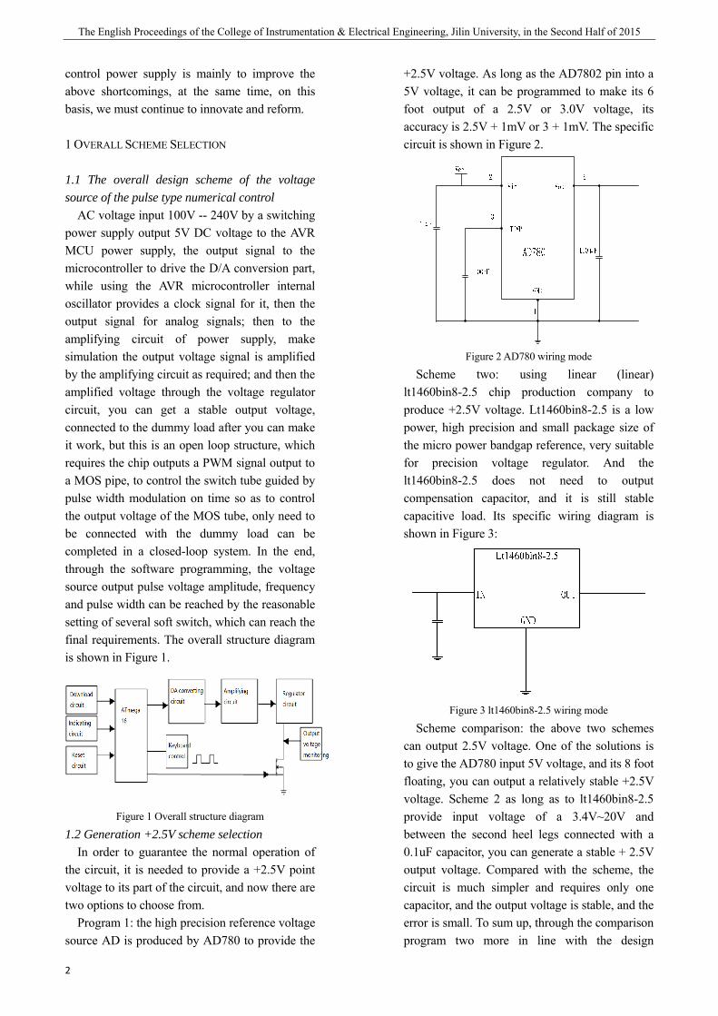
AC voltage input 100V -- 240V by a switching power supply output 5V DC voltage to the AVR MCU power supply, the output signal to the microcontroller to drive the D/A conversion part, while using the AVR microcontroller internal oscillator provides a clock signal for it, then the output signal for analog signals; then to the amplifying circuit of power supply, make simulation the output voltage signal is amplified by the amplifying circuit as required; and then the amplified voltage through the voltage regulator circuit, you can get a stable output voltage, connected to the dummy load after you can make it work, but this is an open loop structure, which requires the chip outputs a PWM signal output to a MOS pipe, to control the switch tube guided by pulse width modulation on time so as to control the output voltage of the MOS tube, only need to be connected with the dummy load can be completed in a closed-loop system. In the end, through the software programming, the voltage source output pulse voltage amplitude, frequency and pulse width can be reached by the reasonable setting of several soft switch, which can reach the final requirements. The overall structure diagram is shown in Figure 1.
Figure 1 Overall structure diagram
1.2 Generation +2.5V scheme selection In order to guarantee the normal operation of
the circuit, it is needed to provide a +2.5V point voltage to its part of the circuit, and now there are two options to choose from.
Program 1: the high precision reference voltage source AD is produced by AD780 to provide the
+2.5V voltage. As long as the AD7802 pin into a 5V voltage, it can be programmed to make its 6 foot output of a 2.5V or 3.0V voltage, its accuracy is 2.5V + 1mV or 3 + 1mV. The specific circuit is shown in Figure 2.
Figure 2 AD780 wiring mode
Scheme two: using linear (linear) lt1460bin8-2.5 chip production company to produce +2.5V voltage. Lt1460bin8-2.5 is a low power, high precision and small package size of the micro power bandgap reference, very suitable for precision voltage regulator. And the lt1460bin8-2.5 does not need to output compensation capacitor, and it is still stable capacitive load. Its specific wiring diagram is shown in Figure 3:
Figure 3 lt1460bin8-2.5 wiring mode
Scheme comparison: the above two schemes can output 2.5V voltage. One of the solutions is to give the AD780 input 5V voltage, and its 8 foot floating, you can output a relatively stable +2.5V voltage. Scheme 2 as long as to lt1460bin8-2.5 provide input voltage of a 3.4V~20V and between the second heel legs connected with a 0.1uF capacitor, you can generate a stable + 2.5V output voltage. Compared with the scheme, the circuit is much simpler and requires only one capacitor, and the output voltage is stable, and the error is small. To sum up, through the comparison program two more in line with the design
Gan Diyuan etc.: Application and Research Design of Numerical Control Voltage Source in Practical Production
3
requirements, so the choice of scheme two. 1.3 Voltage regulator circuit core chip selection
Scheme one: LM317 adjustable three terminal regulator power supply
LM317 is adjustable 3-terminal voltage regulator power supply, it is possible to continuous uninterrupted output can be 1.2 to 37V ADJUSTABLE DC voltage, but the only fly in the ointment is it can output to a continuous tone adjustable positive voltage, not negative output voltage. LM317 regulator contains an internal Overcurrent protection circuit and overheat protection circuit; the output voltage regulating circuit is composed of a resistor and a sliding rheostat.
Program two: the use of CW78XX series three terminal voltage regulator
78XX series are fixed three terminal voltage stabilized power supply, it is by the output (VO), input pin (VI) and ground anchor (GND) the three tube feet, wherein, the input end is connected to a capacitor can better filtering, waveform in order to achieve a better; output end is connected with the capacitor can improve the load at the instant of impact, also can keep good waveform. And the stability of the circuit using 78XX series is also relatively good, reliable, easy to use, and the price is cheap. The input voltage of the 78XX series voltage regulator module is 36V, and the lowest input voltage is higher than the output voltage 3V~4V.
Scheme comparison: the two schemes can be used as the core chip of the construction of the regulator circuit. LM317 is the three terminal adjustable regulator chip, the output voltage adjustable, adjustable range is 1.2V~37V; the maximum current can be provided for 1.5A. CW78XX series is the three terminal fixed regulator chip, using it to build and the required peripheral components is very little, and the circuit has a flow protection circuit, over temperature protection circuit and adjust the protection circuit, the use is very reliable, convenient, and compared with LM317, it can output negative voltage. But the output voltage of the CW78XX series is a fixed value and is not adjustable. In summary, with the design requirements of this paper, the need for a three adjustable voltage regulator chip, so the program is more in line with the design requirements, so
the final choice of a program.
2 WORKING PRINCIPLE OF EACH UNIT CIRCUIT
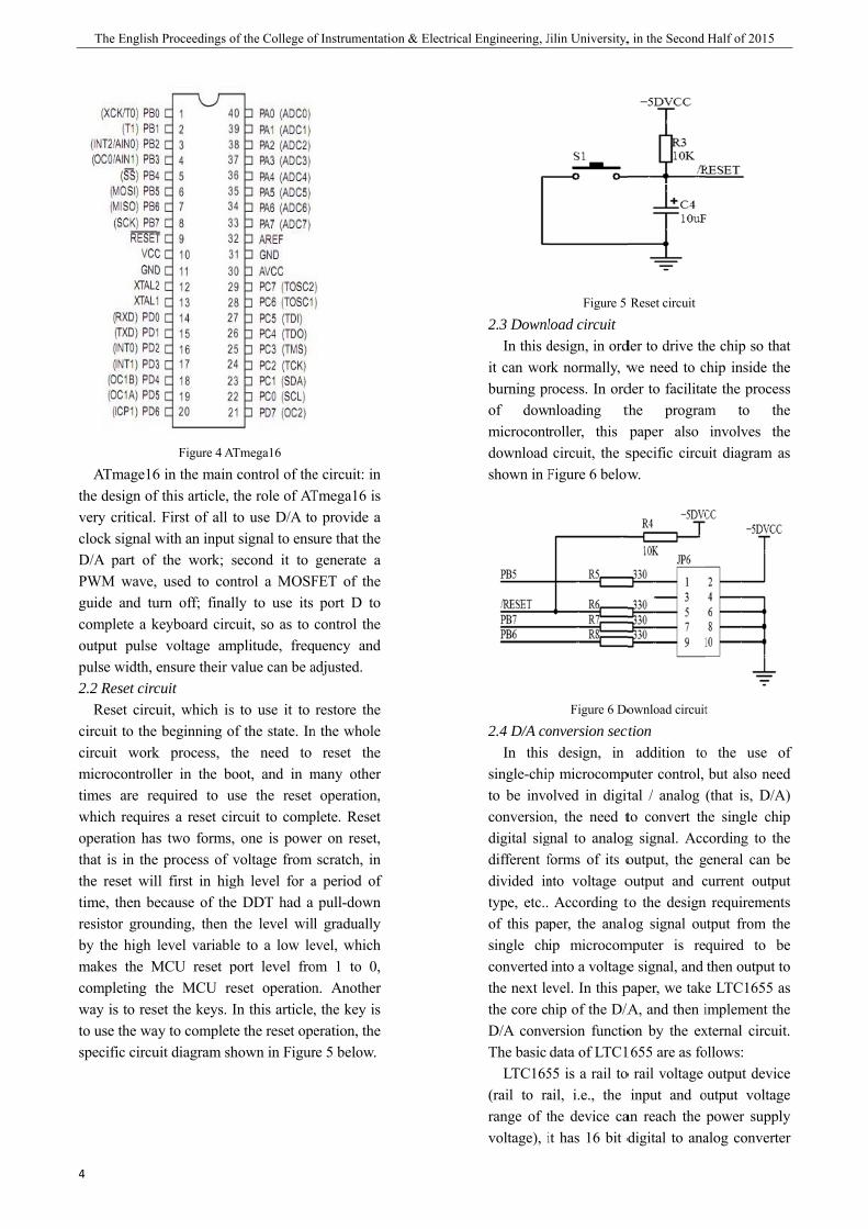
2.1 Control section The design of the numerical control part is
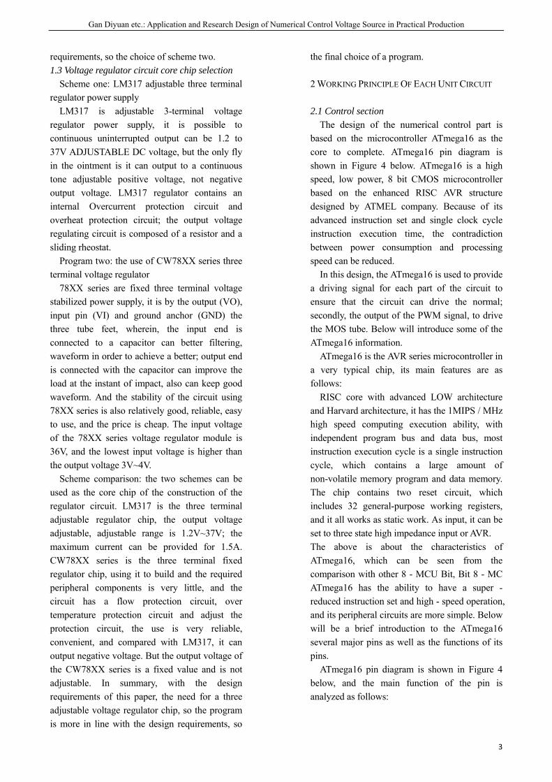
based on the microcontroller ATmega16 as the core to complete. ATmega16 pin diagram is shown in Figure 4 below. ATmega16 is a high speed, low power, 8 bit CMOS microcontroller based on the enhanced RISC AVR structure designed by ATMEL company. Because of its advanced instruction set and single clock cycle instruction execution time, the contradiction between power consumption and processing speed can be reduced.
In this design, the ATmega16 is used to provide a driving signal for each part of the circuit to ensure that the circuit can drive the normal; secondly, the output of the PWM signal, to drive the MOS tube. Below will introduce some of the ATmega16 information.
ATmega16 is the AVR series microcontroller in a very typical chip, its main features are as follows:
RISC core with advanced LOW architecture and Harvard architecture, it has the 1MIPS / MHz high speed computing execution ability, with independent program bus and data bus, most instruction execution cycle is a single instruction cycle, which contains a large amount of non-volatile memory program and data memory. The chip contains two reset circuit, which includes 32 general-purpose working registers, and it all works as static work. As input, it can be set to three state high impedance input or AVR. The above is about the characteristics of ATmega16, which can be seen from the comparison with other 8 - MCU Bit, Bit 8 - MC ATmega16 has the ability to have a super - reduced instruction set and high - speed operation, and its peripheral circuits are more simple. Below will be a brief introduction to the ATmega16 several major pins as well as the functions of its pins.
ATmega16 pin diagram is shown in Figure 4 below, and the main function of the pin is analyzed as follows:
The English
4
ATmage16the design ofvery critical. clock signal wD/A part of PWM wave, guide and tucomplete a koutput pulsepulse width, e2.2 Reset circ
Reset circucircuit to the circuit workmicrocontrolltimes are rewhich requiroperation hasthat is in thethe reset wiltime, then beresistor grouby the high makes the Mcompleting tway is to resto use the waspecific circu
h Proceedings o
Figure 4 AT
6 in the main f this article, t
First of all twith an input the work; s
used to conurn off; finallkeyboard circe voltage amensure their vcuit uit, which is beginning of
k process, thler in the bo
equired to usres a reset cirs two forms,
e process of vll first in higecause of the
unding, then tlevel variable
MCU reset pthe MCU reet the keys. I
ay to completeuit diagram sh
of the College o
Tmega16
control of thethe role of ATto use D/A tosignal to ensu
second it to ntrol a MOSFly to use its uit, so as to
mplitude, freqvalue can be a
to use it to f the state. Inhe need to oot, and in mse the reset rcuit to comp
one is powevoltage from gh level for ae DDT had a the level wile to a low le
port level froeset operationIn this articlee the reset opehown in Figur
f Instrumentatio
e circuit: in Tmega16 is o provide a ure that the generate a
FET of the port D to
control the quency and adjusted.
restore the n the whole
reset the many other
operation, plete. Reset er on reset, scratch, in
a period of pull-down
l gradually evel, which om 1 to 0, n. Another , the key is eration, the re 5 below.
on & Electricall Engineering, J
2.3 DownlIn this d
it can worburning prof downmicrocontdownload shown in F
2.4 D/A coIn this
single-chipto be invoconversiondigital sigdifferent fdivided intype, etc.. of this pasingle chconverted the next lethe core chD/A convThe basic
LTC165(rail to rarange of tvoltage), i
Jilin University,
Figure 5
load circuit design, in ordrk normally, wrocess. In ordnloading throller, this circuit, the s
Figure 6 below
Figure 6 Do
onversion sectdesign, in
p microcompolved in digitn, the need t
gnal to analogforms of its onto voltage o
According tper, the analoip microcominto a voltage
evel. In this phip of the D/Aersion functiodata of LTC1
55 is a rail toail, i.e., the the device cait has 16 bit d
, in the Second
Reset circuit
der to drive thwe need to cder to facilitathe programpaper also specific circuw.
ownload circuit
ction addition to
puter control, tal / analog to convert thg signal. Accoutput, the goutput and cto the design log signal oumputer is ree signal, and
paper, we takeA, and then ion by the ex
1655 are as foo rail voltage
input and oan reach the digital to ana
Half of 2015
he chip so thahip inside the
ate the procesm to theinvolves the
uit diagram a
t
o the use obut also need(that is, D/A
he single chipcording to thegeneral can becurrent outpu
requirementutput from thequired to bethen output toe LTC1655 aimplement thexternal circuitollows:
output deviceoutput voltagepower supply
alog converte
at e s e e s
of d
A) p e e
ut s e e o
as e t.
e e y
er
Gan
(DAC), inclreference, it single chip ctypical powepower supplythe circuit reuse very simp
Fi
2.5 AmplifyinIn this de
output voltagto use an amanalog voltagachieve the paper, the dewith the inteamplifier. OPthe applicatiocases do nomeasures. Its8 below.
From the ffoot is a revegrounding, Ainput, the desthrough D / asignal. OP07
n Diyuan etc.: A
luding an ois the powe
computer, areer consumptioy. And the usquired for theple and reliab
igure 7 D/A con
ng circuit esign, in ordege 24V - 0V cmplifier circge signal amfinal design
esign of the aegrated circuP07 has very lon process, i
ot need addis chip pin diag
Figure 8 OP
figure can be erse input endAnnihilator Tsign of it is da conversion 7 four ground
Application and
output buffeer supply vo +5V voltageon for 3MWse of LTC165e very few co
ble.
nversion circuit
er to achievecan be adjustecuit D/A conmplification, in requiremenamplifier circ
uit OP07 of olow offset voin the vast mitional zero gram is show
P07 pinout
seen, OP07, d, in it througTripods is sadirectly connefrom the anald, seven feet
d Research Desi
er with a oltage of a e, is a very
single 5V 55 to build omponents,
e the final ed, the need nversion of in order to
nts. In this cuit is built operational
oltage, so in majority of adjustment
wn in Figure
the second h a resistor
ame to the ected to the log voltage t by +25V
ign of Numerical Control Volta
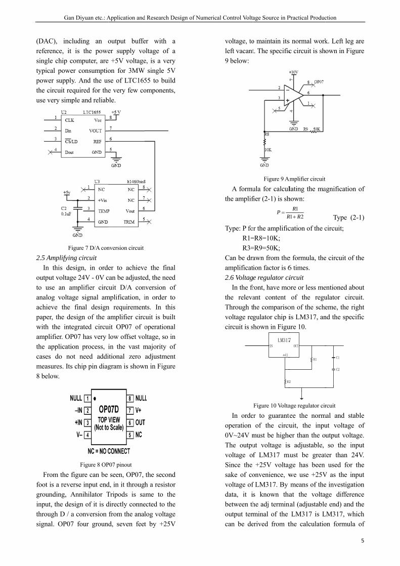
voltage, toleft vacant9 below:
A formuthe amplif
Type: P foR1=R3=
Can be draamplificat2.6 Voltag
In the frthe relevaThrough tvoltage regcircuit is s
In ordeoperation 0V~24V mThe outpuvoltage oSince the sake of covoltage ofdata, it ibetween thoutput termcan be de
age Source in P
o maintain itst. The specific
Figure 9 Am
ula for calculfier (2-1) is sh
r the amplific=R8=10K; =R9=50K; awn from theion factor is 6e regulator ciront, have moant content he comparisogulator chip ihown in Figu
LM317IN
adj
R2
Figure 10 Volta
r to guaranteof the circu
must be higheut voltage isf LM317 mu+25V voltag
onvenience, wf LM317. By s known thahe adj terminminal of the
erived from t
RP =
Practical Produc
s normal workc circuit is sh
Amplifier circuit
lating the mahown:
cation of the c
e formula, the6 times. ircuit ore or less me
of the reguon of the scheis LM317, anure 10.
7 OUT
2
R1
age regulator cir
tee the normuit, the inpuer than the os adjustable,
must be greatge has been we use +25Vmeans of theat the volta
nal (adjustableLM317 is L
the calculatio
211RR
R+
ction
5
k. Left leg areown in Figure
agnification o
Type (2-1circuit;
e circuit of the
entioned abouulator circuiteme, the righnd the specific
C1
C2
rcuit
mal and stableut voltage output voltageso the inpu
ter than 24Vused for the
V as the inpue investigationge differencee end) and the
LM317, whichon formula o
5
e e
of
)
e
ut t.
ht c
e of e. ut V. e
ut n e e h
of

The English
6
the output vformula (2-2)
Type: Uout foR1 for
resistance, thR2 adj
R2 in the pict2.7 Keyboard
As the finaoutput pulsfrequency anorder to facthrough softwachieve its nkeyboard of Figure11.
As shownATmega16 programmablsoftware proeffective or ithe top of ATmega16 psoftware progpull of the controlled byfrequency, puthrough reaachieve the a
3 SOFTWARE
3.1 Program Because it
source, so thhardware cirthe design requirements
Uo
h Proceedings o
voltage of 1.).
for LM317 our the adj end
hat is, R1; to the grounture. d module al design requse voltage nd pulse widthilitate contro
ware programnumerical valf the specific
Figure 11 Keyb
n above, duits PC p
le pull resistoogramming tinvalid, so th
the resistorport of the Pgramming to
effective. y the output pulse width of asonable proabove function
DESIGN SYST
design t is the numis design, in
rcuit, but alsoof the so
s of the final t
(*25.1out =
of the College o
.25V, as sho
utput voltage; d to the out
nd resistance,
uirement is towaveform
h can be adjuol and the k
mming, in the ue can be adc circuit as
board circuit
ue to the sport has aor can be conto pull the ere is no conr, but directPC port, as lo
pull the PC pSix key swpulse voltage the increase oogramming, ns.
TEM
merical contraddition to tho the need tooftware to target. In this
)121(
RR
+
f Instrumentatio
own in the
Type (2-2)
tput of the
that is, the
o make the amplitude,
usted, so in key switch, software to
djusted, the shown in
ingle chip a built-in ntrolled by resistor is
nnection on tly to the ong as the port on the
witches are amplitude,
or decrease you can
rol voltage he need for o complete meet the design, the
on & Electricall Engineering, J
program dvoltage soaspects: fmicrocomsignal. Seinto analoup. 3.2 Progra
The floFigure 12
3.3 PrincipIn this
consider tissues. Ththe variouto ensure tsignal to nto ensure twhich isprogrammpulse voltwidth can use an IF pressed, ifkey is pres
Jilin University,
design of theource includfirst, we muputer, which condly, the d
og signal, the
am block diagow chart of tbelow.
Figure 12 Pro
ples of prograprocess de
the followinge first is to co
us ports and tthat the micronormal drive that each coms the mos
ming. The secotage amplitube adjusted. statement to df no key is pressed, the next
, in the Second
e micro levedes the folloust drive the
can output adigital signalen the output
gram the program
ogram flow cha
am operationesign tasks, g two aspectsonsider the inthe definitionocontroller ou
every level mponent can wst importantond is to achieude, frequencTo achieve thdetermine whessed is out ot step of judg
Half of 2015
el, pulse typeowing severae single chipa PWM drivel is convertedt circuit is se
is shown in
art
the need to
s of the mainnitialization on of variablesut of the driveof the devicework properlyt basis foeve the outpucy and pulsehis, the first tohether a key if the loop, if ament; if a key
e al p e d et
n
o n
of s, er e, y, or ut e o s a y
Gan
is pressed, jitkey is pressedthrough a swis which onereasonable sebounds, it can
4 RESULT AN
4.1 Instrumen1 weldin
suctioner, sci2 measuri
0~30V, digita3 required
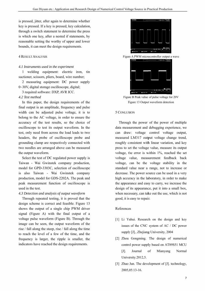
4.2 Test methIn this pap
final output iwidth can bbelong to theaccuracy of oscilloscope test, only neeheaders, the grounding clatwo needles athe output wa
Select the Taiwan - Wmodel for GPis also Taiproduction, mpeak measurused in the te4.3 Detection
Through redesign schemshows the ousignal (Figurvoltage pulseimage can brise / fall alonto reach the frequency isindicators hav
n Diyuan etc.: A
tter, after agad. If a key is
witch statemene key, after a etting the worn meet the de
NALYSIS
nts used in theng equipmenissors, pliers, ing equipmeal storage oscsoftware: DX
hod per, the desiis an amplitudbe adjusted pe AC voltage
the test resto test its ou
ed from acrosprobe of o
amp are respare arranged aveform. test of DC re
Wai GwinstekPD-3303C, siwan - Wamodel for GDrement functest. n and analysisepeated testin
me is correct utput of a sire A) with e waveform (e seen, the ong the steep, level of a fe
s larger, the ve reached th
Application and
ain to determinpressed, key
nt to determinnested if statrthy of upper
esign requirem
e experiment nt: electric board, wire n
ent: DC powilloscope, dig
XP, AVR ICC
gn requiremede, frequencypulse voltage
e, in order to sults, so the utput wavefoss the load leoscilloscope ectively connabove can be
egulated powek company pelection of o
ai Gwinstek DS-2202A. Thtion of oscil
s of output wang, it is provand feasible.
ingle chip PWthe final ou
(Figure B). Toutput waveforise / fall alon
ew of the timripple is sm
he design requ
d Research Desi
ne whether calculation,
ne the press tements, by r and lower ments.
iron, tin number; wer supply gital; .
ents of the y and pulse e, it is to ensure the choice of
orm. In the eads to two probe and
nected with e measured
er supply is production, scilloscope
company he peak and lloscope is
aveform ved that the . Figure 13 WM driver utput of a
Through the form of the ng the time
me, and the maller, the uirements.
ign of Numerical Control Volta
Figure
FigurF
5 CONLUS
Throughdata meascan drawmeasured roughly copress to sevoltage, thvoltage vvoltage, cstandard vdecrease. Thigh accurthe appeardesign of when necegood, it is
Reference
[1] Li Yu
issues
supply
[2] Zhou
contro
[J].
Unive
[3] Zhao J
2005,0
age Source in P
e A PWM micro
re B Peak value igure 13 Output
ION
h the power urement and
w: voltage LM317 outp
onsistent withet the voltagehe error is wvalue, meascan be the value near a The power soracy in the larance and easits appearanc
essary, can takeasy to repair
s
uhui. Researc
of the CNC
y [J]., Zhejiang
Gongming.
ol power suppl
Journal o
rsity.2012,5.
Jun. The deve
05:13-16.
Practical Produc
ocontroller outp
of pulse voltagt waveform dete
of the powedebugging excontrol vol
put voltage ch linear variae value, meas
within 1%, resurement fee
voltage starange, not t
ource can be uaboratory, in osy to carry, wce, put it intoke out the useir.
ch on the de
system of AC
g University, 2
The design
ly based on A
of Mianya
elopment of [J
ction
7
put a wave
ge for 20V ection
er of multiplexperience, weltage outputchange trendation, and keysure its outpueached the seedback back
ability in theto increase oused in a veryorder to make
we increase theo a small boxe, which is no
esign and key
C / DC powe
2004
of numerica
AT89S51 MCU
ang Norma
J]. technology
7
e e t, d, y
ut et k e
or y e e
x, ot
y
er
al
U
al
y,

The English Proceedings of the College of Instrumentation & Electrical Engineering, Jilin University, in the Second Half of 2015
8
[4] left x g. Based on DC voltage source AVR
microcontroller design of [J]. microcomputer
and application, 2012,
[5] Li Shuo. Design and research of remote
wireless monitoring system [J]. Nankai
University, 2006
Pang Shuo etc.: Intelligent anti-theft lock racking system
9
Intelligent anti-theft lock racking system
Pang Shuo; Qujian Fu; Miaolan Li (College of Instrumentation and Electrical Engineering, Jilin University,Changchun 130022,China)
Abstract-An intelligent anti-theft lock tracking system which can fix position automatically was designed. The single chip
microcomputer STC12C5A60S2 is chosen as main controller. And the system is composed of LCD display module, sound
-light alarm module, GSM communication module, GPS module, acceleration module and some other function modules.
When the bike is moved by stranger , the sound light alarm module will take effect, and the position where the bike was
moved will be fixed using GPS module, meanwhile, the location information will be transformed to the owner through short
message by GSM module. The test results show that system position error is less than 5 meters and the information updating
rate is less than 0.2timers/minute.
I.INTRODUCTION
WITH the increasing of social material wealth and the people living standard rise, security becomes one of the most concern of the modern people.In all walks of life, anti-theft alarm is essential, especially the anti-theft lock function.The traditional mechanical lock because of its simple structure, single function, security is very low;The electronic lock overcomes the drawback of mechanical lock safety performance is poor, high confidentiality, use flexibility is good. THIS design increases the GSM module on the basis of electronic lock, GPS positioning module and accelerometer module design smart security lock. Wherein the lock module has a key input display, input error, control alarm, change passwords and other functions; acceleration modules and GPS positioning module can sense when the car is stolen the car to move and achieve positioning; GSM communication module can send text messages to notify the owner to achieve accurate positioning stolen, to ensure the safety of the car.
II.PROCEDURE FOR PAPER SUBMISSION
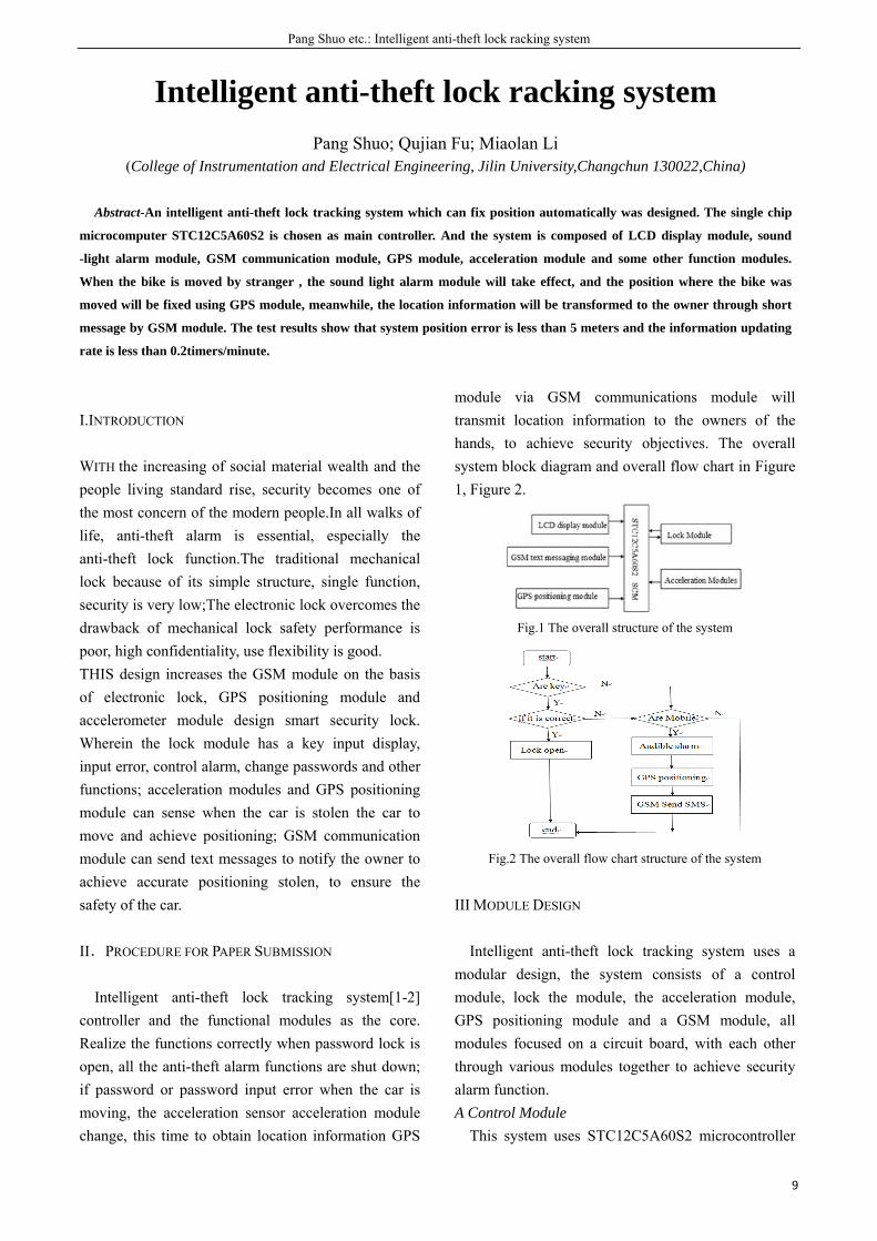
Intelligent anti-theft lock tracking system[1-2] controller and the functional modules as the core. Realize the functions correctly when password lock is open, all the anti-theft alarm functions are shut down; if password or password input error when the car is moving, the acceleration sensor acceleration module change, this time to obtain location information GPS
module via GSM communications module will transmit location information to the owners of the hands, to achieve security objectives. The overall system block diagram and overall flow chart in Figure 1, Figure 2.
Fig.1 The overall structure of the system
Fig.2 The overall flow chart structure of the system
III MODULE DESIGN
Intelligent anti-theft lock tracking system uses a modular design, the system consists of a control module, lock the module, the acceleration module, GPS positioning module and a GSM module, all modules focused on a circuit board, with each other through various modules together to achieve security alarm function. A Control Module
This system uses STC12C5A60S2 microcontroller
The English Proceedings of the College of Instrumentation & Electrical Engineering, Jilin University, in the Second Half of 2015
10
as the controller, which comes with an internal MCU 60K FLASH ROM, can instantly erase the way electricity, rewrite, support for serial has been programmed, conducive to achieving the program online programming. Meanwhile a high-speed, low power consumption, superior anti-jamming, etc., will help reduce system weight, good stability.
The most important thing is, STC12C5A60S2 microcontroller has two serial ports (RXD, TXD and RXD1, TXD1), GPS module can be implemented simultaneously with the GSM module is connected to the microcontroller. 1 serial connection with the GPS positioning module, serial port 2 is connected with GSM communication modules. After the success of GPS positioning, the location information sent to the microcontroller through the serial port 1, and then sends the location information string to the serial port 2, port 2 interrupt function control use, store the received data, the last data will be sent to the owner of the phone, it can be easily dual serial communication. B Lock Module
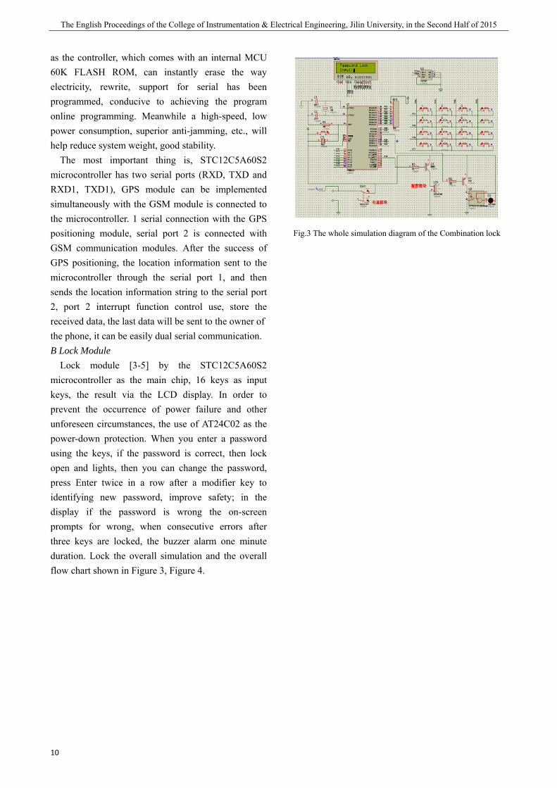
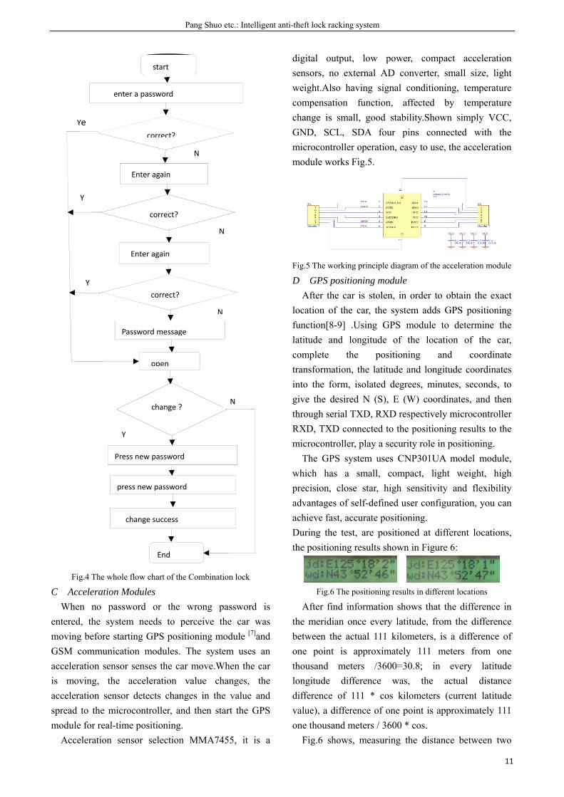
Lock module [3-5] by the STC12C5A60S2 microcontroller as the main chip, 16 keys as input keys, the result via the LCD display. In order to prevent the occurrence of power failure and other unforeseen circumstances, the use of AT24C02 as the power-down protection. When you enter a password using the keys, if the password is correct, then lock open and lights, then you can change the password, press Enter twice in a row after a modifier key to identifying new password, improve safety; in the display if the password is wrong the on-screen prompts for wrong, when consecutive errors after three keys are locked, the buzzer alarm one minute duration. Lock the overall simulation and the overall flow chart shown in Figure 3, Figure 4.
Fig.3 The whole simulation diagram of the Combination lock
Pang Shuo etc.: Intelligent anti-theft lock racking system
11
Fig.4 The whole flow chart of the Combination lock
C Acceleration Modules When no password or the wrong password is
entered, the system needs to perceive the car was moving before starting GPS positioning module [7]and GSM communication modules. The system uses an acceleration sensor senses the car move.When the car is moving, the acceleration value changes, the acceleration sensor detects changes in the value and spread to the microcontroller, and then start the GPS module for real-time positioning.
Acceleration sensor selection MMA7455, it is a
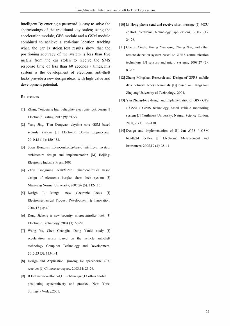
digital output, low power, compact acceleration sensors, no external AD converter, small size, light weight.Also having signal conditioning, temperature compensation function, affected by temperature change is small, good stability.Shown simply VCC, GND, SCL, SDA four pins connected with the microcontroller operation, easy to use, the acceleration module works Fig.5.
Fig.5 The working principle diagram of the acceleration module
D GPS positioning module After the car is stolen, in order to obtain the exact
location of the car, the system adds GPS positioning function[8-9] .Using GPS module to determine the latitude and longitude of the location of the car, complete the positioning and coordinate transformation, the latitude and longitude coordinates into the form, isolated degrees, minutes, seconds, to give the desired N (S), E (W) coordinates, and then through serial TXD, RXD respectively microcontroller RXD, TXD connected to the positioning results to the microcontroller, play a security role in positioning.
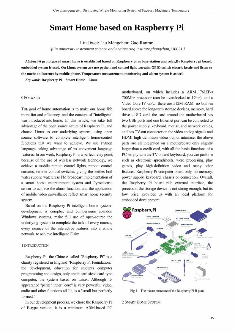
The GPS system uses CNP301UA model module, which has a small, compact, light weight, high precision, close star, high sensitivity and flexibility advantages of self-defined user configuration, you can achieve fast, accurate positioning. During the test, are positioned at different locations, the positioning results shown in Figure 6:
Fig.6 The positioning results in different locations
After find information shows that the difference in the meridian once every latitude, from the difference between the actual 111 kilometers, is a difference of one point is approximately 111 meters from one thousand meters /3600=30.8; in every latitude longitude difference was, the actual distance difference of 111 * cos kilometers (current latitude value), a difference of one point is approximately 111 one thousand meters / 3600 * cos.
Fig.6 shows, measuring the distance between two
Ye
N
Enter again
Y
correct?
N
Enter again
Y correct?
N
Password message
open
change ? N
Y
Press new password
press new password
change success
End
correct?
start
enter a password

The English Proceedings of the College of Instrumentation & Electrical Engineering, Jilin University, in the Second Half of 2015
12
anchor points meridian of 1 minute * 30.8 m / min = 30.8 m, measuring the distance on the weft of 1 minute * 30.8 m / min * cos43 °= 22.5 meters and the overall measurement distance meters.The actual distance between the two places is about 36 meters, so the error within five meters, and the difference between the actual distance of 2.1 meters, the error is about 5%.The error depends largely on the model selected GPS module, for higher positioning accuracy, can choose more accurate GPS positioning module. E GSM communication module
When the car is stolen, if they can accurately informed of the specific location of the car, for the recovery of stolen vehicles have a key role.Therefore, you can use GSM communication module[10-12] GPS positioning information in real time sent to the owner of the phone, so that owners can grasp the orientation of the car lies.The system uses SIM900A communication module to send and receive text messages to communicate with the owners of mobile phones, SIM900A communication module with low power consumption, among other functions and receive calls, GSM module complete with computer data communication via AT commands, you need to set the mode to send short messages Text format and determines that the received number information.Working SIM900A communication module flow chart shown in Fig.7
Fig.7 The work flow chart of SIM900A communication modul
IV TEST RESULTS
After the commissioning of each module, the overall system were tested.
Locks can achieve the basic functions, when the correct password is entered open lock indicator lights, have three input opportunities buzzer alarm if the three are wrong, and in the case of lock open can change the password.Enter the password to change the password display shows the results and the results shown in Fig. 8 and 9.
Fig.8 The results when entering the password
Fig.9 The results when changeing the password
GPS module can locate the current latitude and longitude, when the car began to locate stolen, and the location information sent via GSM module to the owner of the phone,Fig.10.
Fig.10 Mobile phone received positioning information
V EPILOGUE
We completed the design and testing of intelligent anti-theft lock tracking system.On the basis of traditional electronic locks, an increase of password protection and real-time positioning, more
start
Start GSM
The connection is successful?
Setting GSM Character Set
Set the text mode
Determine the phone number
Texting
Delay
End
Y
N
Pang Shuo etc.: Intelligent anti-theft lock racking system
13
intelligent.By entering a password is easy to solve the shortcomings of the traditional key stolen; using the acceleration module, GPS module and a GSM module combined to achieve a real-time location tracking when the car is stolen.Test results show that the positioning accuracy of the system is less than five meters from the car stolen to receive the SMS response time of less than 60 seconds / times.This system is the development of electronic anti-theft locks provide a new design ideas, with high value and development potential.
References
[1] Zhang Yongqiang high reliability electronic lock design [J]
Electronic Testing, 2012 (9): 91-95.
[2] Yang Jing, Tian Dengyao, daytime core GSM based
security system [J] Electronic Design Engineering,
2010,18 (11): 150-153.
[3] Shen Hongwei microcontroller-based intelligent system
architecture design and implementation [M] Beijing:
Electronic Industry Press, 2002.
[4] Zhou Gongming AT89C2051 microcontroller based
design of electronic burglar alarm lock system [J]
Mianyang Normal University, 2007,26 (5): 112-115.
[5] Design Li Mingxi new electronic locks [J]
Electromechanical Product Development & Innovation,
2004,17 (3): 40.
[6] Dong Jicheng a new security microcontroller lock [J]
Electronic Technology, 2004 (3): 58-60.
[7] Wang Yu, Chen Changjia, Dong Yanlei study [J]
acceleration sensor based on the vehicle anti-theft
technology Computer Technology and Development,
2013,23 (5): 135-141.
[8] Design and Application Qiuzong De spaceborne GPS
receiver [J] Chinese aerospace, 2003.11: 23-26.
[9] B.Hofmann-Wellonhof,H.Lichtenegger,J.Collins.Global
positioning system:theory and practice. New York:
Springer- Verlag,2001.
[10] Li Hong phone send and receive short message [J] MCU
control electronic technology applications, 2003 (1):
24-26.
[11] Cheng, Creek, Huang Yuanqing, Zhang Xin, and other
remote detection system based on GPRS communication
technology [J] sensors and micro systems, 2008,27 (2):
83-85.
[12] Zhang Mingshan Research and Design of GPRS mobile
data network access terminals [D] based on Hangzhou:
Zhejiang University of Technology, 2004.
[13] Yan Zheng-long design and implementation of GIS / GPS
/ GSM / GPRS technology based vehicle monitoring
system [J] Northwest University: Natural Science Edition,
2008,38 (1): 127-130.
[14] Design and implementation of BI Jun .GPS / GSM
handheld locator [J] Electronic Measurement and
Instrument, 2005,19 (3): 38-41

Cao zhan-peng etc.: Distributed Wirele Monitoring System of Factrory Machinery Temperature
15
Smart Home based on Raspberry Pi
Liu Jiwei; Liu Mengchen; Gao Ranran (jilin university instrument science and engineering institute,changchun,130021)
Abstract-A prototype of smart home is established based on Raspberry pi as base-station and relay,By Raspberry pi board,
embedded system is used. On Linux system ,we use python and control light ,curtain, GPIO,switch electric kettle and listen to
the music on Internet by mobile phone. Temperature measurement, monitoring and alarm system is as well.
Key words-Raspberry Pi Smart Home Linux
0 FORWARD
THE goal of home automation is to make our home life more fun and efficiency, and the concept of "intelligent" was introduced into home. In this article, we take full advantage of the open source nature of Raspberry Pi, and choose Linux as our underlying system, using open source software to complete intelligent home-control functions that we want to achieve. We use Python language, taking advantage of its convenient language features. In our work, Raspberry Pi is a perfect relay point, because of the use of wireless network technology, we achieve a mobile remote control lights, remote control curtains, remote control switches giving the kettles boil water supply, watercress FM broadcast implementation of a smart home entertainment system and Pyroelectric sensor to achieve the alarm function, and the application of mobile video surveillance reflect smart home security system.
Based on the Raspberry Pi intelligent home systems development is complex and cumbersome abandon Windows systems, make full use of open-source the underlying system to complete the task of every nuance, every nuance of the interactive features into a whole network, to achieve intelligent Claim.
1 INTRODUCTION
Raspberry Pi, the Chinese called "Raspberry Pi" is a charity registered in England "Raspberry Pi Foundation," the development, education for students computer programming and design, only credit card sized card-type computer, the system based on Linux. Although its appearance "petite" inner "core" is very powerful, video, audio and other functions all Jie, is a "small but perfectly formed."
In our development process, we chose the Raspberry Pi of B-type version, it is a miniature ARM-based PC
motherboard, on which includes a ARM1176JZF-s 700Mhz processor (can be overclocked to 1Ghz), and a Video Core IV GPU, there are 512M RAM, no built-in board above the long-term storage devices, memory, hard drive to SD card, the card around the motherboard has two USB ports and one Ethernet port can be connected to the power supply, keyboard, mouse, and network cables, and has TV-out connector on the video analog signals and HDMI high definition video output interface, the above parts are all integrated on a motherboard only slightly larger than a credit card, with all the basic functions of a PC simply turn the TV on and keyboard, you can perform such as electronic spreadsheets, word processing, play games, play high-definition video and many other features. Raspberry Pi computer board only, no memory, power supply, keyboard, chassis or connection. Overall, the Raspberry Pi board rich external interface, the processor, the storage device is not strong enough, but its low price, provides us with an ideal platform for embedded development.
Fig 1 The macro-structure of the Raspberry Pi B plate
2 SMART HOME SYSTEM
The English Proceedings of the College of Instrumentation & Electrical Engineering, Jilin University, in the Second Half of 2015
16
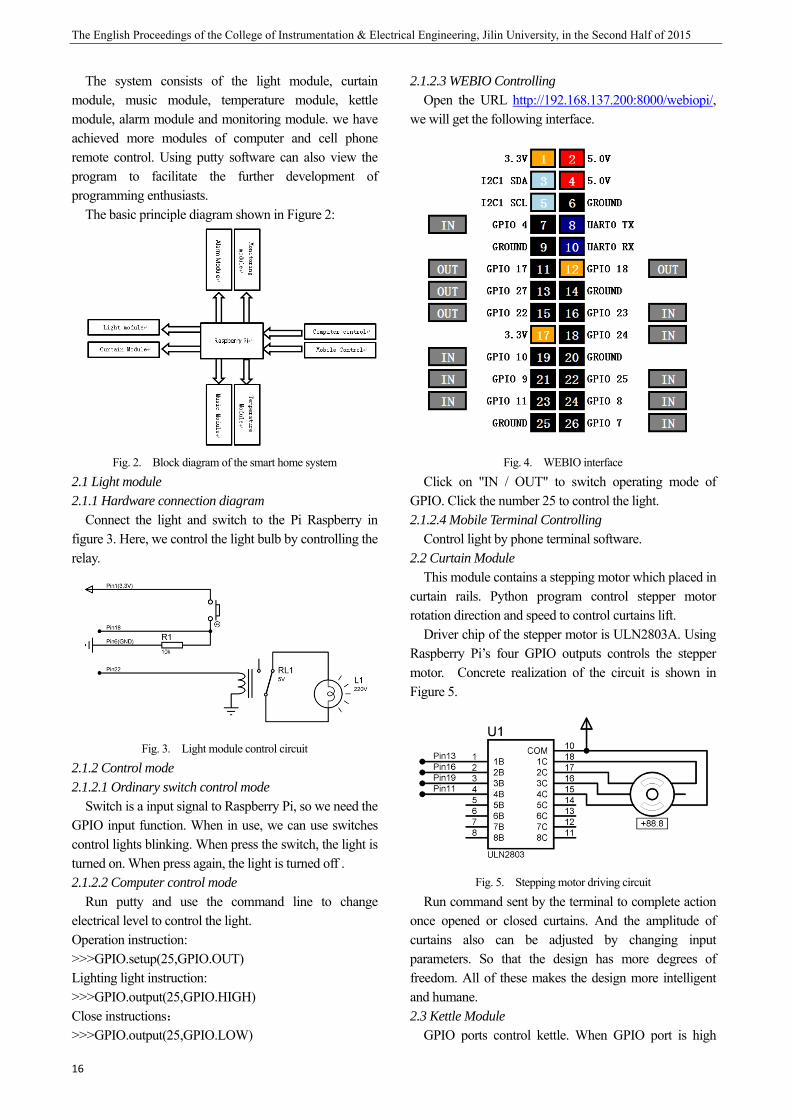
The system consists of the light module, curtain module, music module, temperature module, kettle module, alarm module and monitoring module. we have achieved more modules of computer and cell phone remote control. Using putty software can also view the program to facilitate the further development of programming enthusiasts.
The basic principle diagram shown in Figure 2:
Fig. 2. Block diagram of the smart home system
2.1 Light module 2.1.1 Hardware connection diagram
Connect the light and switch to the Pi Raspberry in figure 3. Here, we control the light bulb by controlling the relay.
Fig. 3. Light module control circuit
2.1.2 Control mode 2.1.2.1 Ordinary switch control mode
Switch is a input signal to Raspberry Pi, so we need the GPIO input function. When in use, we can use switches control lights blinking. When press the switch, the light is turned on. When press again, the light is turned off . 2.1.2.2 Computer control mode
Run putty and use the command line to change electrical level to control the light. Operation instruction: >>>GPIO.setup(25,GPIO.OUT) Lighting light instruction: >>>GPIO.output(25,GPIO.HIGH) Close instructions: >>>GPIO.output(25,GPIO.LOW)
2.1.2.3 WEBIO Controlling Open the URL http://192.168.137.200:8000/webiopi/,
we will get the following interface.
Fig. 4. WEBIO interface
Click on "IN / OUT" to switch operating mode of GPIO. Click the number 25 to control the light. 2.1.2.4 Mobile Terminal Controlling
Control light by phone terminal software. 2.2 Curtain Module
This module contains a stepping motor which placed in curtain rails. Python program control stepper motor rotation direction and speed to control curtains lift.
Driver chip of the stepper motor is ULN2803A. Using Raspberry Pi’s four GPIO outputs controls the stepper motor. Concrete realization of the circuit is shown in Figure 5.
Fig. 5. Stepping motor driving circuit
Run command sent by the terminal to complete action once opened or closed curtains. And the amplitude of curtains also can be adjusted by changing input parameters. So that the design has more degrees of freedom. All of these makes the design more intelligent and humane. 2.3 Kettle Module
GPIO ports control kettle. When GPIO port is high
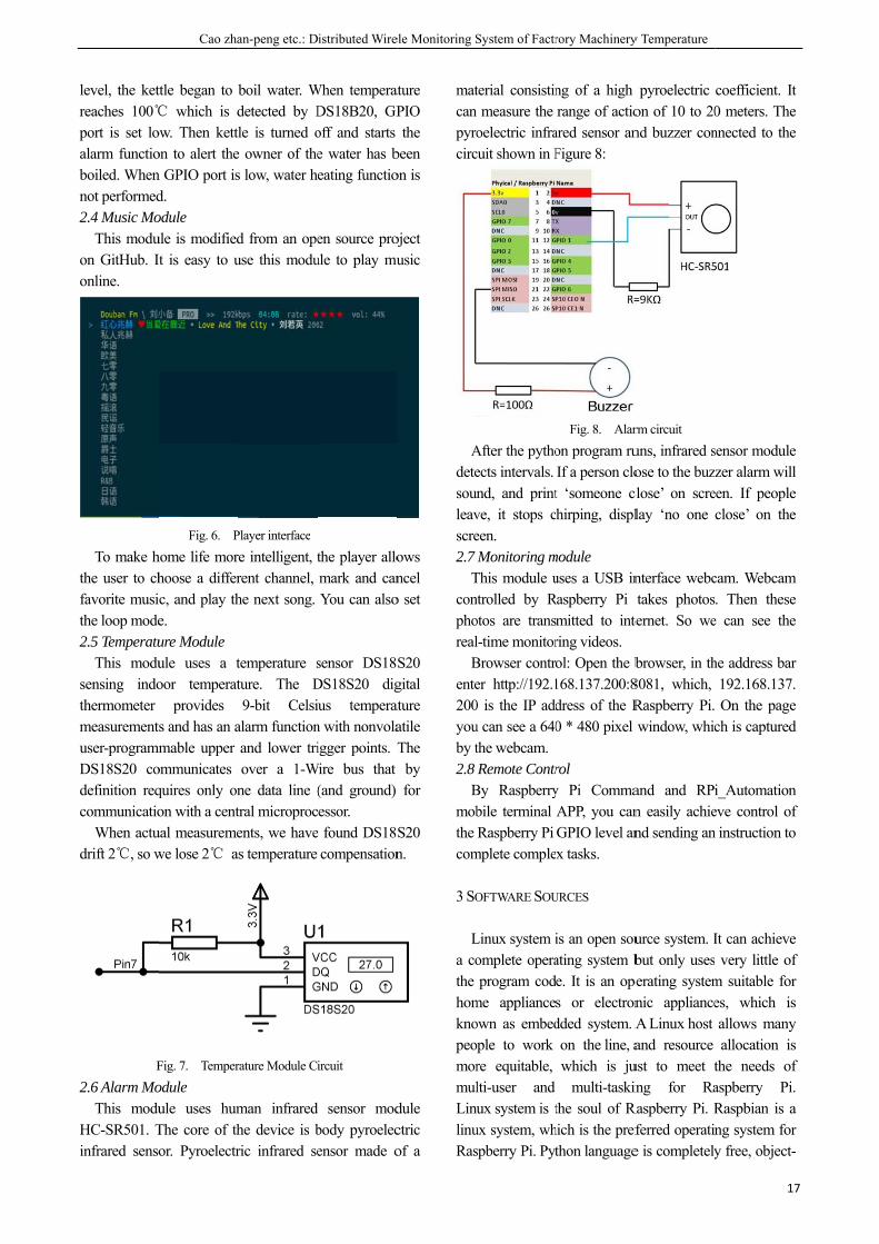
level, the ketreaches 100℃port is set loalarm functioboiled. Whennot performed2.4 Music Mo
This moduon GitHub. Ionline.
To make hthe user to chfavorite musithe loop mode2.5 Temperatu
This modusensing indothermometer measurementuser-programmDS18S20 codefinition reqcommunicatio
When actudrift 2℃, so w
F
2.6 Alarm MoThis modu
HC-SR501. Tinfrared senso
Cao zha
ttle began to b℃ which is dow. Then kettlon to alert then GPIO port isd. odule ule is modifiedIt is easy to u
Fig. 6. P
home life morhoose a differc, and play the. ure Module ule uses a toor temperat
provides s and has an a
mmable upper ommunicates quires only onon with a cent
ual measuremewe lose 2℃ a
Fig. 7. Temper
odule ule uses humThe core of thor. Pyroelectr
an-peng etc.: D
boil water. Wdetected by Dle is turned o
e owner of thes low, water h
d from an opeuse this modu
Player interface
re intelligent, trent channel, he next song.
temperature sture. The D9-bit Celsi
alarm functionand lower triover a 1-W
ne data line (tral microprocents, we haves temperature
rature Module Ci
man infrared he device is bric infrared se
istributed Wire
When temperatDS18B20, GPoff and starts e water has beating functio
en source projule to play mu
the player allomark and canYou can also
sensor DS18DS18S20 digius temperatn with nonvolaigger points. T
Wire bus that (and ground) essor.
e found DS18compensation
ircuit
sensor modbody pyroelecensor made o
ele Monitoring S
ature PIO the
been on is
oject usic
ows ncel
o set
S20 gital ature atile The
by for
S20 n.
dule ctric of a
matcan pyrocirc
Adetesounleavscre2.7
Tconphoreal
Bente200youby t2.8
Bmobthe com
3 SO
La cothe homknopeomormulLinulinuRas
System of Factr
terial consistinmeasure the
oelectric infracuit shown in F
After the pythoects intervals. nd, and printve, it stops ceen. Monitoring m
This module untrolled by Rotos are transl-time monitorBrowser controer http://192.10 is the IP addu can see a 640the webcam.Remote Contr
By Raspberrybile terminal Raspberry Pi
mplete comple
OFTWARE SOU
Linux system iomplete operaprogram cod
me applianceown as embedople to work re equitable, lti-user and ux system is t
ux system, whspberry Pi. Pyt
rory Machinery
ng of a high range of actio
ared sensor anFigure 8:
Fig. 8. Alar
on program ruIf a person clot ‘someone clhirping, displ
module uses a USB in
Raspberry Pi mitted to intering videos. ol: Open the b168.137.200:8dress of the R0 * 480 pixel
rol y Pi CommaAPP, you canGPIO level anx tasks.
URCES
is an open souating system be. It is an opes or electrondded system. Aon the line, awhich is ju
multi-taskinthe soul of R
hich is the prefthon language
y Temperature
pyroelectric on of 10 to 20nd buzzer con
rm circuit
uns, infrared sose to the buz
close’ on screlay ‘no one
nterface webctakes photos
ternet. So we
browser, in th8081, which, Raspberry Pi. window, whic
and and RPin easily achiend sending an
urce system. Ibut only useserating systemnic applianceA Linux host and resource
ust to meet ting for Ra
Raspberry Pi. Rferred operatine is completely
17
coefficient. It0 meters. Thennected to the
sensor modulezer alarm will
een. If peopleclose’ on the
cam. Webcam. Then these
e can see the
he address bar192.168.137.On the page
ch is captured
i_Automationeve control ofn instruction to
It can achievevery little of
m suitable fores, which isallows manyallocation is
the needs ofaspberry Pi.Raspbian is ang system fory free, object-
7
t e e
e l e e
m e e
r . e d
n f o
e f r s y s f . a r -
The English Proceedings of the College of Instrumentation & Electrical Engineering, Jilin University, in the Second Half of 2015
18
oriented, easy to learn and portability, and it has access to the underlying hardware and control it. So python is an excellent choice to control hardware based on Raspberry Pi.
4 SYSTEM TEST RESULTS
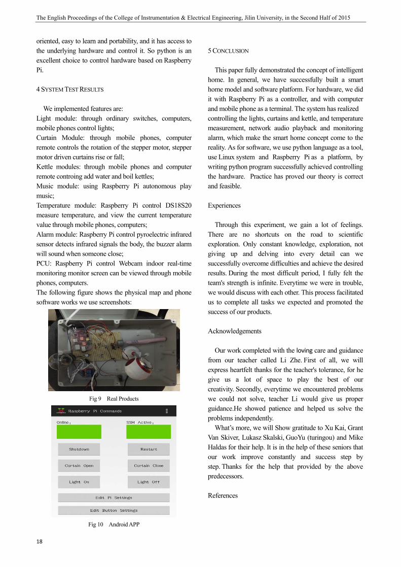
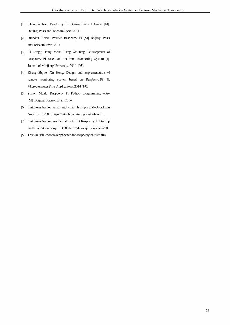
We implemented features are: Light module: through ordinary switches, computers, mobile phones control lights; Curtain Module: through mobile phones, computer remote controls the rotation of the stepper motor, stepper motor driven curtains rise or fall; Kettle modules: through mobile phones and computer remote controing add water and boil kettles; Music module: using Raspberry Pi autonomous play music; Temperature module: Raspberry Pi control DS18S20 measure temperature, and view the current temperature value through mobile phones, computers; Alarm module: Raspberry Pi control pyroelectric infrared sensor detects infrared signals the body, the buzzer alarm will sound when someone close; PCU: Raspberry Pi control Webcam indoor real-time monitoring monitor screen can be viewed through mobile phones, computers. The following figure shows the physical map and phone software works we use screenshots:
Fig 9 Real Products
Fig 10 Android APP
5 CONCLUSION
This paper fully demonstrated the concept of intelligent home. In general, we have successfully built a smart home model and software platform. For hardware, we did it with Raspberry Pi as a controller, and with computer and mobile phone as a terminal. The system has realized controlling the lights, curtains and kettle, and temperature measurement, network audio playback and monitoring alarm, which make the smart home concept come to the reality. As for software, we use python language as a tool, use Linux system and Raspberry Pi as a platform, by writing python program successfully achieved controlling the hardware. Practice has proved our theory is correct and feasible.
Experiences
Through this experiment, we gain a lot of feelings. There are no shortcuts on the road to scientific exploration. Only constant knowledge, exploration, not giving up and delving into every detail can we successfully overcome difficulties and achieve the desired results. During the most difficult period, I fully felt the team's strength is infinite. Everytime we were in trouble, we would discuss with each other. This process facilitated us to complete all tasks we expected and promoted the success of our products.
Acknowledgements
Our work completed with the loving care and guidance from our teacher called Li Zhe. First of all, we will express heartfelt thanks for the teacher's tolerance, for he give us a lot of space to play the best of our creativity. Secondly, everytime we encountered problems we could not solve, teacher Li would give us proper guidance.He showed patience and helped us solve the problems independently.
What’s more, we will Show gratitude to Xu Kai, Grant Van Skiver, Lukasz Skalski, GuoYu (turingou) and Mike Haldas for their help. It is in the help of these seniors that our work improve constantly and success step by step. Thanks for the help that provided by the above predecessors.
References
Cao zhan-peng etc.: Distributed Wirele Monitoring System of Factrory Machinery Temperature
19
[1] Chen Jianhao. Raspberry Pi Getting Started Guide [M].
Beijing: Posts and Telecom Press, 2014.
[2] Brendan Horan. Practical Raspberry Pi [M] Beijing: Posts
and Telecom Press, 2014.
[3] Li Longqi, Fang Meifa, Tang Xiaoteng. Development of
Raspberry Pi based on Real-time Monitoring System [J].
Journal of Minjiang University, 2014 (05).
[4] Zheng Shijue, Xu Hong. Design and implementation of
remote monitoring system based on Raspberry Pi [J].
Microcomputer & its Applications, 2014 (19).
[5] Simon Monk. Raspberry Pi Python programming entry
[M]. Beijing: Science Press, 2014.
[6] Unknown Author. A tiny and smart cli player of douban.fm in
Node. js [EB/OL]. https://github.com/turingou/douban.fm
[7] Unknown Author. Another Way to Let Raspberry Pi Start up
and Run Python Script[EB/OL]http://shumeipai.nxez.com/20
[8] 15/02/09/run-python-script-when-the-raspberry-pi-start.html

Cao zhan-peng etc.: Distributed Wirele Monitoring System of Factrory Machinery Temperature
21
Distributed Wirele Monitoring System of Factory Machinery Temperature
Cao zhan-peng; Zhou bo; Mu-tingting (School of Instrument Science and electrical engineering, Jilin University, Changchun 130022)
Abstract-The paper introduce a design that monitors temperature and humidity for short distance , which is based on low
energy consumption and high performance micro controller STC89C52RC and temperature sensor DHT11, and uses
wireless module nRF24L01. Because of the large factory environment, the real-time changes and uneven distribution of
temperature and humidity is caused. If we adopt the traditional way of the measurement circuit ,it will be very
complex, vulnerable to be distracted, and accuracy is not high, does not meet certain harsh industrial environment
and some outdoor environment. Therefore, choosing a good digital temperature ,a wireless transmission module and simple to
use is particularly important.This design has low power consumption, low cost, simple hardware circuit, high
receiving sensitivity, receiving and transmitting distance is about 100 meters, it is a feasible method.
Keywords-NRF24L01; temperature and humidity sensor DHT11; STC89C52RC
1 .INTRODUCTION
WITH the development of society, Our requirement
to the temperature and humidity of environmental is
higher and higher, especially in the pharmaceutical,
food, aviation, microelectronics and other fields.
For the daily management of factory, the
temperature and humidity will directly affect the
service life and safety reliability of the factory items.
Therefore, A system that is capable of accurate,
stable, real-time monitoring of temperature and
humidity is particularly important. In some cases,
we need to monitor a large extent, the wiring is not
convenient and not conducive to post-maintenance,
then we use wireless modules for temperature
acquisition.
Taking into account that there are demands for
multi-point temperature monitoring the environment
in many factories, so we design a distributed factory
wireless temperature monitoring system. We adopt
NRF24L01 as wireless communication module and
STC89C52RC as the core to control the temperature
and humidity to achieve short-range wireless
transmission. The whole design of the master and
slave modules are connected through wireless
communications module NRF24L01. The core of
slave is microcontroller STC89C52,and the slave
transmits temperature that collected by the
temperature sensors to the host via the wireless
module NRF24L01, the master receives
temperature data via the wireless module
NRF24L01, and then the data displays on the
liquid crystal LCD1602, so as to achieve the
purpose of monitoring. Finally, the temperature
and humidity data received by sensor can be sent to
the host from two slaves via the wireless module in
the range of 5m, the host received the data via the
wireless module and the data is displayed on the
LCD1602 LCD, so as to achieve the purpose of
monitoring the temperature and humidity.
The system is designed with low cost, fast
transmission, low power consumption and high
reliability,and the software design is simple.
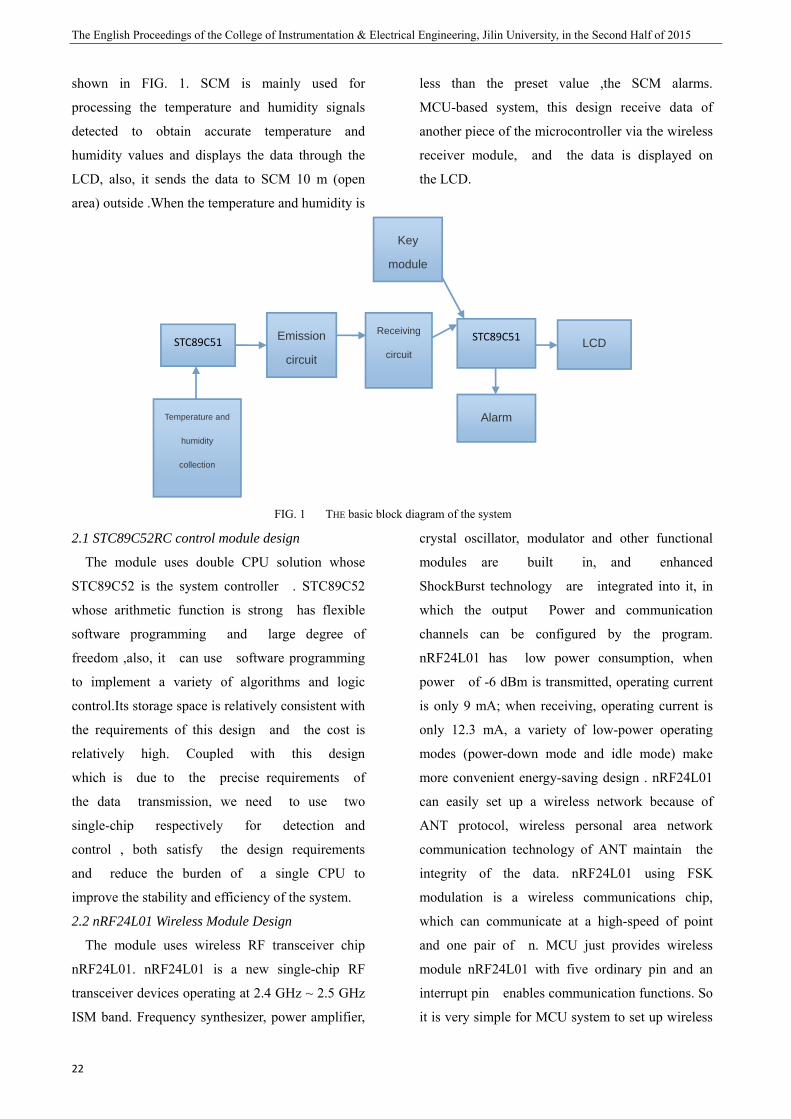
2.HARDWARE SYSTEM DESIGN
The basic block diagram of the system is as
The English Proceedings of the College of Instrumentation & Electrical Engineering, Jilin University, in the Second Half of 2015
22
shown in FIG. 1. SCM is mainly used for
processing the temperature and humidity signals
detected to obtain accurate temperature and
humidity values and displays the data through the
LCD, also, it sends the data to SCM 10 m (open
area) outside .When the temperature and humidity is
less than the preset value ,the SCM alarms.
MCU-based system, this design receive data of
another piece of the microcontroller via the wireless
receiver module, and the data is displayed on
the LCD.
FIG. 1 THE basic block diagram of the system
2.1 STC89C52RC control module design
The module uses double CPU solution whose
STC89C52 is the system controller . STC89C52
whose arithmetic function is strong has flexible
software programming and large degree of
freedom ,also, it can use software programming
to implement a variety of algorithms and logic
control.Its storage space is relatively consistent with
the requirements of this design and the cost is
relatively high. Coupled with this design
which is due to the precise requirements of
the data transmission, we need to use two
single-chip respectively for detection and
control , both satisfy the design requirements
and reduce the burden of a single CPU to
improve the stability and efficiency of the system.
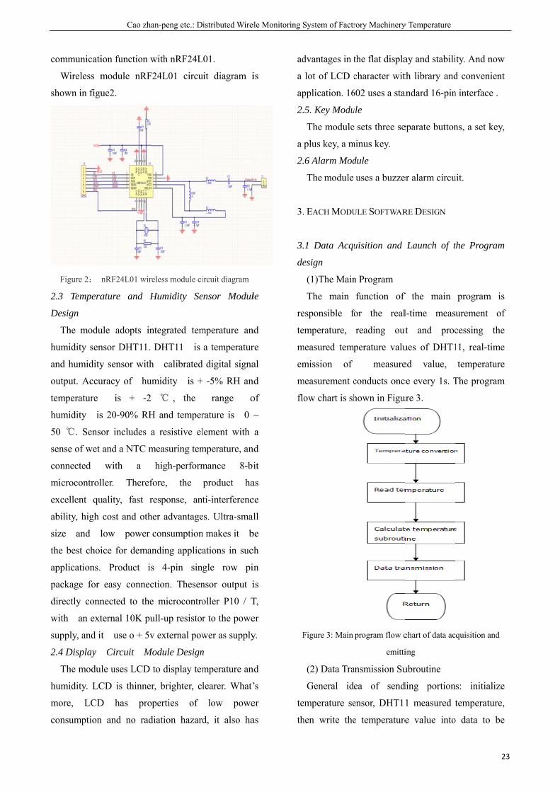
2.2 nRF24L01 Wireless Module Design
The module uses wireless RF transceiver chip
nRF24L01. nRF24L01 is a new single-chip RF
transceiver devices operating at 2.4 GHz ~ 2.5 GHz
ISM band. Frequency synthesizer, power amplifier,
crystal oscillator, modulator and other functional
modules are built in, and enhanced
ShockBurst technology are integrated into it, in
which the output Power and communication
channels can be configured by the program.
nRF24L01 has low power consumption, when
power of -6 dBm is transmitted, operating current
is only 9 mA; when receiving, operating current is
only 12.3 mA, a variety of low-power operating
modes (power-down mode and idle mode) make
more convenient energy-saving design . nRF24L01
can easily set up a wireless network because of
ANT protocol, wireless personal area network
communication technology of ANT maintain the
integrity of the data. nRF24L01 using FSK
modulation is a wireless communications chip,
which can communicate at a high-speed of point
and one pair of n. MCU just provides wireless
module nRF24L01 with five ordinary pin and an
interrupt pin enables communication functions. So
it is very simple for MCU system to set up wireless
STC89C51 Emission
circuit
Key
module
Receiving
circuit
STC89C51 LCD
Alarm Temperature and
humidity
collection
D
communicati
Wireless m
shown in figu
Figure 2:
2.3 Tempera
Design
The modu
humidity sen
and humidity
output. Accu
temperature
humidity is
50 ℃. Senso
sense of wet
connected
microcontrol
excellent qu
ability, high
size and l
the best choi
applications.
package for
directly conn
with an ext
supply, and it
2.4 Display
The modul
humidity. LC
more, LCD
consumption
Cao zha
ion function w
module nRF
ue2.
nRF24L01 wire
ature and H
ule adopts in
nsor DHT11.
y sensor with
uracy of hum
is + -2
s 20-90% RH
or includes a
and a NTC m
with a
ller. Theref
uality, fast r
cost and oth
low power
ice for deman
Product is
easy connec
nected to the
ternal 10K pu
t use o + 5v
Circuit M
le uses LCD
CD is thinner
D has pro
n and no rad
an-peng etc.: D
with nRF24L
24L01 circu
eless module ci
Humidity Se
ntegrated tem
DHT11 is
h calibrated
midity is +
℃ , the
H and temper
a resistive el
measuring tem
high-perform
fore, the
response, an
her advantage
consumption
nding applica
s 4-pin sin
ction. Thesen
e microcontro
ull-up resistor
v external pow
Module Design
to display tem
r, brighter, cl
perties of
diation hazard
istributed Wire
L01.
uit diagram i
ircuit diagram
ensor Modul
mperature an
a temperatur
d digital signa
+ -5% RH an
range o
rature is 0 ~
lement with
mperature, an
mance 8-b
product ha
ti-interferenc
es. Ultra-smal
n makes it b
ations in suc
gle row pi
nsor output i
oller P10 / T
r to the powe
wer as supply
n
mperature an
learer. What’
low powe
d, it also ha
ele Monitoring S
is
le
nd
re
al
nd
of
~
a
nd
it
as
ce
all
be
ch
in
is
T,
er
y.
nd
’s
er
as
ad
a
ap
2.
a
2.
3.
3.
de
re
te
m
em
m
flo
F
te
th
System of Factr
dvantages in t
lot of LCD c
pplication. 16
5. Key Modu
The module
plus key, a m
6 Alarm Mod
The module
. EACH MODU
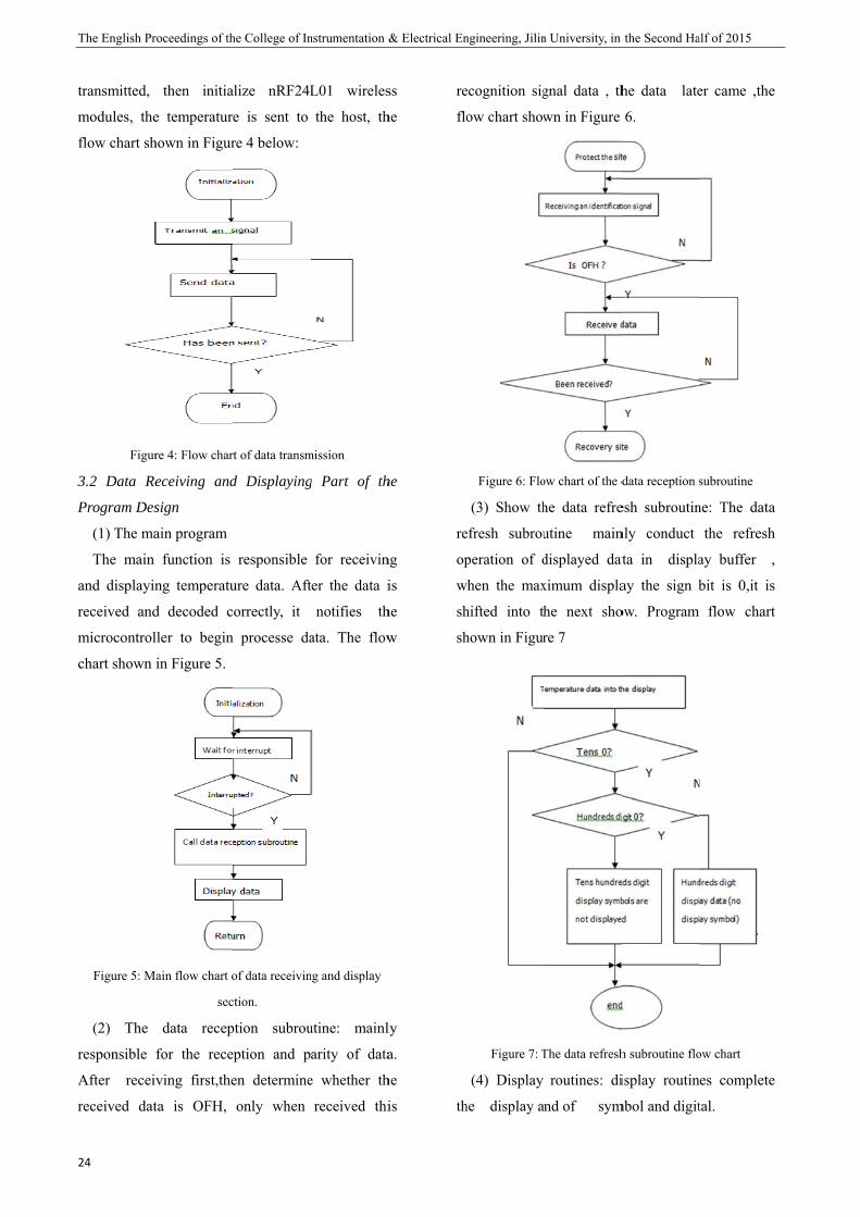
1 Data Acqu
esign
(1)The Main
The main
esponsible fo
emperature,
measured temp
mission of
measurement c
ow chart is sh
Figure 3: Main
(2) Data Tra
General id
emperature se
hen write the
rory Machinery
the flat displa
character wit
602 uses a sta
ule
sets three se
minus key.
dule
uses a buzze
ULE SOFTWAR
uisition and
n Program
function of
for the real
reading out
perature valu
measure
conducts onc
hown in Figu
program flow c
emitti
ansmission Su
ea of send
ensor, DHT1
e temperature
y Temperature
ay and stabili
th library and
andard 16-pin
eparate button
er alarm circu
RE DESIGN
Launch of t
f the main
l-time meas
ut and proc
ues of DHT1
ed value,
ce every 1s. T
ure 3.
chart of data ac
ing
ubroutine
ding portion
1 measured t
e value into
23
ity. And now
d convenient
n interface .
ns, a set key,
uit.
the Program
program is
urement of
cessing the
11, real-time
temperature
The program
quisition and
s: initialize
temperature,
o data to be
3
P
The English Pr
24
transmitted,
modules, the
flow chart sh
Figur
3.2 Data Re
Program Des
(1) The ma
The main
and displayin
received and
microcontrol
chart shown
Figure 5: M
(2) The
responsible
After receiv
received dat
roceedings of th
then initia
e temperature
hown in Figur
re 4: Flow char
eceiving and
sign
ain program
function is
ng temperatu
d decoded c
ller to begin
in Figure 5.
ain flow chart o
sec
data recep
for the rece
ving first,the
ta is OFH,
he College of In
alize nRF24L
e is sent to
re 4 below:
rt of data transm
d Displaying
responsible
ure data. Aft
orrectly, it
n processe da
of data receivin
ction.
ption subrou
ption and p
en determine
only when
nstrumentation &
L01 wireles
the host, th
mission
g Part of th
for receivin
ter the data i
notifies th
ata. The flow
ng and display
utine: mainl
arity of data
e whether th
received thi
& Electrical En
ss
he
he
ng
is
he
w
ly
a.
he
is
re
flo
re
op
w
sh
sh
th
ngineering, Jilin
ecognition sig
ow chart show
Figure 6: Flo
(3) Show th
efresh subrou
peration of d
when the max
hifted into th
hown in Figur
Figure 7: T
(4) Display
he display a
n University, in
gnal data , th
wn in Figure
ow chart of the d
he data refre
utine main
displayed dat
ximum displa
he next sho
re 7
The data refresh
routines: di
nd of sym
the Second Ha
he data late
6.
data reception s
esh subroutin
nly conduct
ata in displa
ay the sign b
ow. Program
h subroutine flo
isplay routin
mbol and digit
alf of 2015
er came ,the
subroutine
ne: The data
the refresh
ay buffer ,
bit is 0,it is
flow chart
ow chart
es complete
tal.
Cao zhan-peng etc.: Distributed Wirele Monitoring System of Factrory Machinery Temperature
25
4. DEBUGGING AND EXPERIMENTAL RESULTS OF
SYSTEM
4.1 Commissioning Procedure
Step 1: Complete welding of hardware circuit.
Step 2: First, write a simple test procedures to test
display of LCD1602 whether is no problem.
Step 3: Make microcontroller of the receiving
portion connect with a single digital, write the
program of the measurement of temperature and
humidity . Test hardware and software relating to
DHT11.
Step 4: Build a simple wireless communication
hardware, write a simple test sequencing , detecte
transceiver hardware modules.
Step 5: Write all the sequencing together,
build a complete hardware of a master and
two slave , also, detect whether the system can
display the temperature value measured
from two slave on the LCD1602 via the
wireless module.
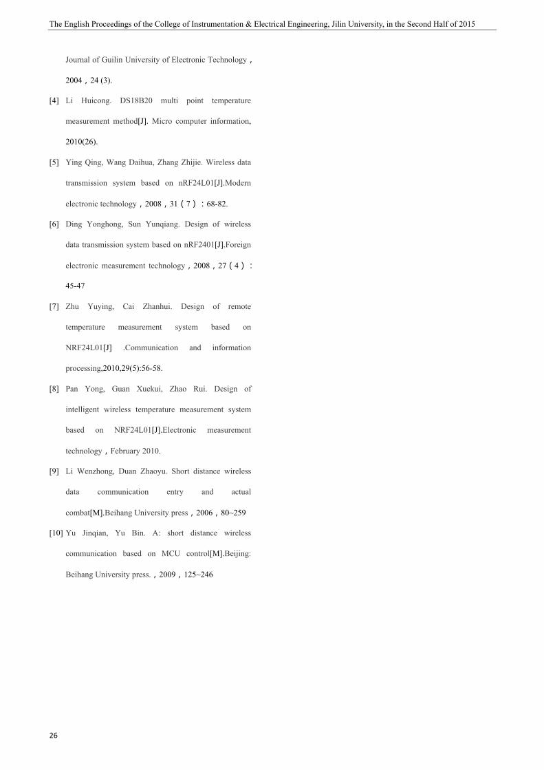
4.2 Experimental Results
The following figure is the master of wireless
temperature and humidity test systems, immediately
complete LCD1602 initialization when it’s powered,
and waits for receiving data coming from the
transmission side and display it on the LCD1602
in real time.
Figure8:Host of the wireless system of testing temperature
and humidity.
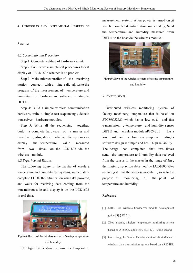
The figure is a slave of wireless temperature
measurement system. When power is turned on ,it
will be completed initialization immediately, Send
the temperature and humidity measured from
DHT11 to the host via the wireless module .
Figure9:Slave of the wireless system of testing temperature
and humidity.
5. CONCLUSIONS
Distributed wireless monitoring System of
factory machinery temperature that is based on
STC89C52RC which has a low cost and fast
transmission , temperature and humidity sensor
DHT11 and wireless module nRF24L01 has a
low cost and a low consumption also,its
software design is simple and has high reliability .
The design has completed that two slaves
send the temperature and humidity data recieved
from the sensor to the master in the range of 5m ,
the master display the data on the LCD1602 after
receiving it via the wireless module , so as to the
purpose of monitoring all the point of
temperature and humidity.
Reference
[1] NRF24L01 wireless transceiver module development
guide [S](V3.2)
[2] Zhou Yuanju, wireless temperature monitoring system
based on AT89S52 and NRF24L01 [J]. 2012 second
[3] Guo Gang, Li Simin. Development of short distance
wireless data transmission system based on nRF24E1.
The English Proceedings of the College of Instrumentation & Electrical Engineering, Jilin University, in the Second Half of 2015
26
Journal of Guilin University of Electronic Technology,
2004,24 (3).
[4] Li Huicong. DS18B20 multi point temperature
measurement method[J]. Micro computer information,
2010(26).
[5] Ying Qing, Wang Daihua, Zhang Zhijie. Wireless data
transmission system based on nRF24L01[J].Modern
electronic technology,2008,31(7):68-82.
[6] Ding Yonghong, Sun Yunqiang. Design of wireless
data transmission system based on nRF2401[J].Foreign
electronic measurement technology,2008,27(4):
45-47
[7] Zhu Yuying, Cai Zhanhui. Design of remote
temperature measurement system based on
NRF24L01[J] .Communication and information
processing,2010,29(5):56-58.
[8] Pan Yong, Guan Xuekui, Zhao Rui. Design of
intelligent wireless temperature measurement system
based on NRF24L01[J].Electronic measurement
technology,February 2010.
[9] Li Wenzhong, Duan Zhaoyu. Short distance wireless
data communication entry and actual
combat[M].Beihang University press,2006,80~259
[10] Yu Jinqian, Yu Bin. A: short distance wireless
communication based on MCU control[M].Beijing:
Beihang University press.,2009,125~246
Jiang yanhui etc.: The design of semiconductor laser modulation circuit based on DDS technology
27
The design of semiconductor laser modulation circuit based on DDS technology
Jiang yanhui; Sun chaofan; Chen wenxing
( Instrument science and electrical engineering , Jilin University,Changchun 130022) Abstract-The detection method of wavelength modulation based on DFB laser can make the detection sensitivity higher than
the direct absorption method even 2 to 3 orders of magnitude .Therefore, there is very important practical value to
design DFB Laser driver .
Key words-DFB Laser driver ; gas concentration detection; direct digital frequency synthesis technology; sinusoidal wave
signal generator
Ⅰ.INTRODUCTION
COAL mine gas explosion occurred frequently in China, which has brought great loss to people's life safety and property security.Therefore, it plays an important role in the detection of gas concentration.Gas concentration detection is mostly based on infrared gas analysis method, semiconductor laser is a common source of light.The drive of the traditional laser is the use of analog electronic components to build, but the simulation circuit debugging difficult, not easy to quickly get the need of the driver signal.In recent years, with the development of digital technology, using digital method to drive laser not only can quickly get the driving signal, so that the same laser can be used in different situations.Most of the existing DDS signal generator does not have the ability to drive the DFB laser, so it is necessary to study the DDS signal generator with the ability of driving laser.
Ⅱ.TEXT
2.1 DDS technology 2.1.1 The principle and character of DDS technology
DDS is a high precision clock signal as a reference, by the phase accumulator and register, in the sine look-up table to find corresponding amplitude information, through D / A converter get
corresponding digital signal, and then use a low-pass filter, the final output sine signal.As shown in Figure 1, the corresponding relationship between the phase and the amplitude is as follows:
Figure 1:Phase and amplitude map
The sine wave shape can be regarded as a vector of the vector along the phase circle, the phase circle corresponds to a periodic wave of the sine wave.Each sample point in the waveform corresponds to a phase point on a circle. 2.1.2 theory and configuration of DDS
DDS block diagram is shown in Figure 2,contains the phase accumulator, waveform memory, analog-to-digital converter, low pass filter and a reference clock of five parts.Under the control of a reference clock, input frequency control word, the phase accumulator for the frequency control word K were linear superposition, the phase code of waveform memory addressing and magnitude to output the corresponding code, through the digital to analog converter get corresponding ladder wave, the low pass filter by continuous changes in the desired frequency of the waveform.
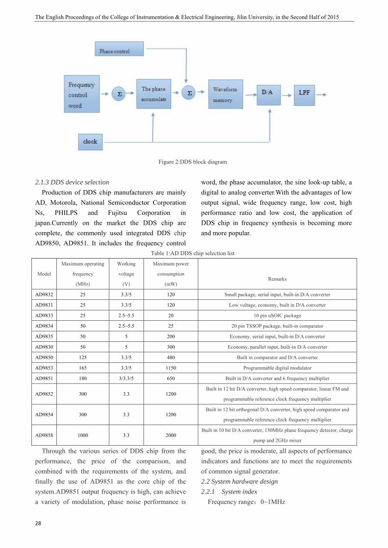
The English Proceedings of the College of Instrumentation & Electrical Engineering, Jilin University, in the Second Half of 2015
28
Figure 2:DDS block diagram
2.1.3 DDS device selection
Production of DDS chip manufacturers are mainly AD, Motorola, National Semiconductor Corporation Ns, PHILPS and Fujitsu Corporation in japan.Currently on the market the DDS chip are complete, the commonly used integrated DDS chip AD9850, AD9851. It includes the frequency control
word, the phase accumulator, the sine look-up table, a digital to analog converter.With the advantages of low output signal, wide frequency range, low cost, high performance ratio and low cost, the application of DDS chip in frequency synthesis is becoming more and more popular.
Table 1:AD DDS chip selection list
Model
Maximum operating
frequency
(MHz)
Working
voltage
(V)
Maximum power
consumption
(mW)
Remarks
AD9832 25 3.3/5 120 Small package, serial input, built-in D/A converter
AD9831 25 3.3/5 120 Low voltage, economy, built in D/A converter
AD9833 25 2.5~5.5 20 10 pin uSOIC package
AD9834 50 2.5~5.5 25 20 pin TSSOP package, built-in comparator
AD9835 50 5 200 Economy, serial input, built-in D/A converter
AD9830 50 5 300 Economy, parallel input, built-in D/A converter
AD9850 125 3.3/5 480 Built in comparator and D/A converter
AD9853 165 3.3/5 1150 Programmable digital modulator
AD9851 180 3/3.3/5 650 Built in D/A converter and 6 frequency multiplier
AD9852 300 3.3 1200 Built in 12 bit D/A converter, high speed comparator, linear FM and
programmable reference clock frequency multiplier
AD9854 300 3.3 1200 Built in 12 bit orthogonal D/A converter, high speed comparator and
programmable reference clock frequency multiplier
AD9858 1000 3.3 2000 Built in 10 bit D/A converter, 150MHz phase frequency detector, charge
pump and 2GHz mixer
Through the various series of DDS chip from the performance, the price of the comparison, and combined with the requirements of the system, and finally the use of AD9851 as the core chip of the system.AD9851 output frequency is high, can achieve a variety of modulation, phase noise performance is
good, the price is moderate, all aspects of performance indicators and functions are to meet the requirements of common signal generator. 2.2 System hardware design 2.2.1 System index
Frequency range:0~1MHz
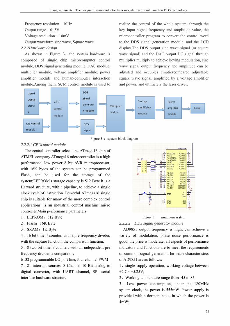
Jiang yanhui etc.: The design of semiconductor laser modulation circuit based on DDS technology
29
Frequency resolution:10Hz Output range:0~5V Voltage resolution:10mV Output waveform:sine wave, Square wave
2.2.2Hardware design As shown in Figure 3,the system hardware is
composed of single chip microcomputer control module, DDS signal generating module, DAC module, multiplier module, voltage amplifier module, power amplifier module and human-computer interaction module.Among them, SCM control module is used to
realize the control of the whole system, through the key input signal frequency and amplitude value, the microcontroller program to convert the control word to the DDS signal generation module, and the LCD display.The DDS output sine wave signal (or square wave signal) and the DAC output DC signal through multiplier multiply to achieve keying modulation, sine wave signal output frequency and amplitude can be adjusted and occupies emptiescompared adjustable square wave signal, amplified by a voltage amplifier and power, and ultimately the laser driver.
Figure 3 :system block diagram
2.2.2.1 CPUcontrol module The central controller selects the ATmega16 chip of
ATMEL company.ATmega16 microcontroller is a high performance, low power 8 bit AVR microprocessor, with 16K bytes of the system can be programmed Flash, can be used for the storage of the system;EEPROM's storage capacity is 512 Byte.It is a Harvard structure, with a pipeline, to achieve a single clock cycle of instruction. Powerful ATmega16 single chip is suitable for many of the more complex control applications, is an industrial control machine micro controller.Main performance parameters: 1、EEPROM:512 Byte 2、Flash:16K Byte 3、SRAM:1K Byte 4、16 bit timer / counter: with a pre frequency divider, with the capture function, the comparison function; 5、8 two bit timer / counter: with an independent pre frequency divider, a comparator; 6、32 programmable I/O port line, four channel PWM; 7、21 interrupt sources, 8 Channel 10 Bit analog to digital converter, with UART channel, SPI serial interface hardware structure.
Figure 5: minimum system
2.2.2.2 DDS signal generator module AD9851 output frequency is high, can achieve a
variety of modulation, phase noise performance is good, the price is moderate, all aspects of performance indicators and functions are to meet the requirements of common signal generator.The main characteristics of AD9851 are as follows: 1、single supply operation, working voltage between +2.7 ~ +5.25V; 2、Working temperature range from -45 to 85; 3、Low power consumption, under the 180MHz system clock, the power is 555mW. Power supply is provided with a dormant state, in which the power is 4mW;
Liquid
crystal
displa
y
Key control
module
CPU
control
module
DDS
signal
generato
r module
DDS
signal
Multiplier
module
Voltage
amplifying
module
Power
amplifier
module
Laser
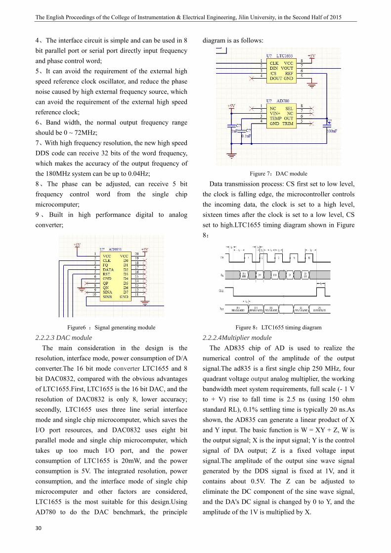
The English Proceedings of the College of Instrumentation & Electrical Engineering, Jilin University, in the Second Half of 2015
30
4、The interface circuit is simple and can be used in 8 bit parallel port or serial port directly input frequency and phase control word; 5、It can avoid the requirement of the external high speed reference clock oscillator, and reduce the phase noise caused by high external frequency source, which can avoid the requirement of the external high speed reference clock; 6、Band width, the normal output frequency range should be 0 ~ 72MHz; 7、With high frequency resolution, the new high speed DDS code can receive 32 bits of the word frequency, which makes the accuracy of the output frequency of the 180MHz system can be up to 0.04Hz; 8、The phase can be adjusted, can receive 5 bit frequency control word from the single chip microcomputer; 9 、 Built in high performance digital to analog converter;
Figure6 :Signal generating module
2.2.2.3 DAC module The main consideration in the design is the
resolution, interface mode, power consumption of D/A converter.The 16 bit mode converter LTC1655 and 8 bit DAC0832, compared with the obvious advantages of LTC1655.First, LTC1655 is the 16 bit DAC, and the resolution of DAC0832 is only 8, lower accuracy; secondly, LTC1655 uses three line serial interface mode and single chip microcomputer, which saves the I/O port resources, and DAC0832 uses eight bit parallel mode and single chip microcomputer, which takes up too much I/O port, and the power consumption of LTC1655 is 20mW, and the power consumption is 5V. The integrated resolution, power consumption, and the interface mode of single chip microcomputer and other factors are considered, LTC1655 is the most suitable for this design.Using AD780 to do the DAC benchmark, the principle
diagram is as follows:
Figure 7:DAC module
Data transmission process: CS first set to low level, the clock is falling edge, the microcontroller controls the incoming data, the clock is set to a high level, sixteen times after the clock is set to a low level, CS set to high.LTC1655 timing diagram shown in Figure 8:
Figure 8:LTC1655 timing diagram
2.2.2.4Multiplier module The AD835 chip of AD is used to realize the
numerical control of the amplitude of the output signal.The ad835 is a first single chip 250 MHz, four quadrant voltage output analog multiplier, the working bandwidth meet system requirements, full scale (- 1 V to + V) rise to fall time is 2.5 ns (using 150 ohm standard RL), 0.1% settling time is typically 20 ns.As shown, the AD835 can generate a linear product of X and Y input. The basic function is W = XY + Z, W is the output signal; X is the input signal; Y is the control signal of DA output; Z is a fixed voltage input signal.The amplitude of the output sine wave signal generated by the DDS signal is fixed at 1V, and it contains about 0.5V. The Z can be adjusted to eliminate the DC component of the sine wave signal, and the DA's DC signal is changed by 0 to Y, and the amplitude of the 1V is multiplied by X.
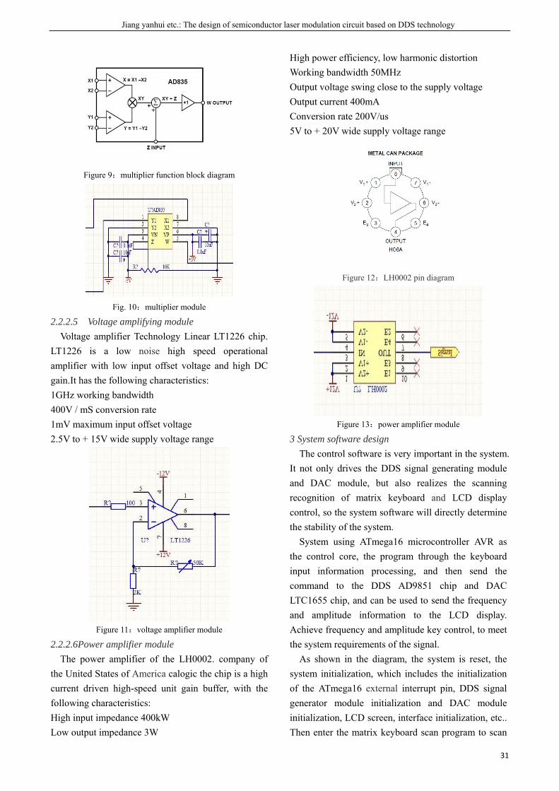
Jiang yanhui etc.: The design of semiconductor laser modulation circuit based on DDS technology
31
Figure 9:multiplier function block diagram
Fig. 10:multiplier module
2.2.2.5 Voltage amplifying module Voltage amplifier Technology Linear LT1226 chip.
LT1226 is a low noise high speed operational amplifier with low input offset voltage and high DC gain.It has the following characteristics: 1GHz working bandwidth 400V / mS conversion rate 1mV maximum input offset voltage 2.5V to + 15V wide supply voltage range
Figure 11:voltage amplifier module
2.2.2.6Power amplifier module The power amplifier of the LH0002. company of
the United States of America calogic the chip is a high current driven high-speed unit gain buffer, with the following characteristics: High input impedance 400kW Low output impedance 3W
High power efficiency, low harmonic distortion Working bandwidth 50MHz Output voltage swing close to the supply voltage Output current 400mA Conversion rate 200V/us 5V to + 20V wide supply voltage range
Figure 12:LH0002 pin diagram
Figure 13:power amplifier module
3 System software design The control software is very important in the system.
It not only drives the DDS signal generating module and DAC module, but also realizes the scanning recognition of matrix keyboard and LCD display control, so the system software will directly determine the stability of the system.
System using ATmega16 microcontroller AVR as the control core, the program through the keyboard input information processing, and then send the command to the DDS AD9851 chip and DAC LTC1655 chip, and can be used to send the frequency and amplitude information to the LCD display. Achieve frequency and amplitude key control, to meet the system requirements of the signal.
As shown in the diagram, the system is reset, the system initialization, which includes the initialization of the ATmega16 external interrupt pin, DDS signal generator module initialization and DAC module initialization, LCD screen, interface initialization, etc.. Then enter the matrix keyboard scan program to scan
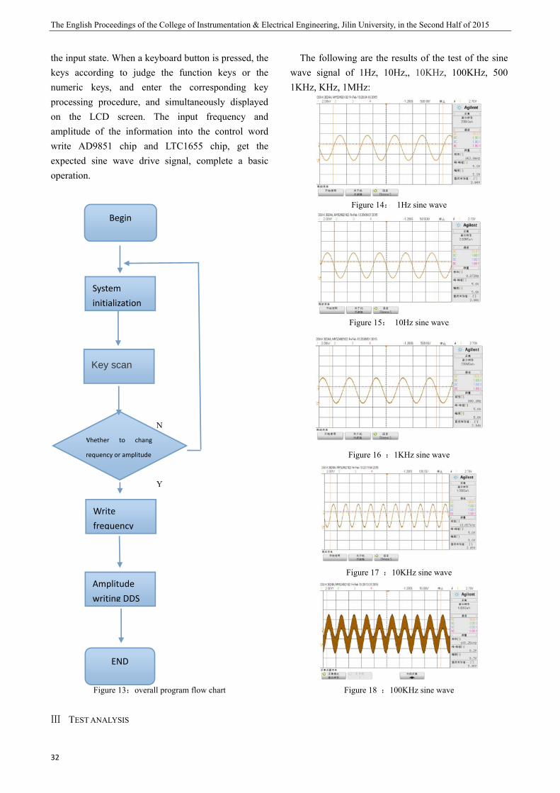
The English Proceedings of the College of Instrumentation & Electrical Engineering, Jilin University, in the Second Half of 2015
32
the input state. When a keyboard button is pressed, the keys according to judge the function keys or the numeric keys, and enter the corresponding key processing procedure, and simultaneously displayed on the LCD screen. The input frequency and amplitude of the information into the control word write AD9851 chip and LTC1655 chip, get the expected sine wave drive signal, complete a basic operation.
N
Y
Figure 13:overall program flow chart
Ⅲ TEST ANALYSIS
The following are the results of the test of the sine wave signal of 1Hz, 10Hz,, 10KHz, 100KHz, 500 1KHz, KHz, 1MHz:
Figure 14: 1Hz sine wave
Figure 15: 10Hz sine wave
Figure 16 :1KHz sine wave
Figure 17 :10KHz sine wave
Figure 18 :100KHz sine wave
Begin
System initialization
Key scan
Amplitude writing DDS
Write frequency
END
Whether to chang
requency or amplitude
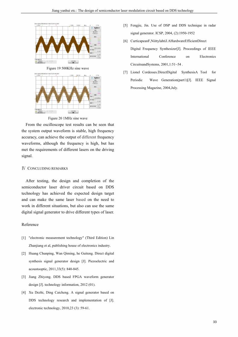
Jiang yanhui etc.: The design of semiconductor laser modulation circuit based on DDS technology
33
Figure 19 500KHz sine wave
Figure 20 1MHz sine wave
From the oscilloscope test results can be seen that the system output waveform is stable, high frequency accuracy, can achieve the output of different frequency waveforms, although the frequency is high, but has met the requirements of different lasers on the driving signal.
Ⅳ CONCLUDING REMARKS
After testing, the design and completion of the semiconductor laser driver circuit based on DDS technology has achieved the expected design target and can make the same laser based on the need to work in different situations, but also can use the same digital signal generator to drive different types of laser.
Reference
[1] "electronic measurement technology" (Third Edition) Lin
Zhanjiang et al, publishing house of electronics industry.
[2] Huang Chunping, Wan Qiming, he Guiteng. Direct digital
synthesis signal generator design [J]. Piezoelectric and
acoustooptic, 2011,33(5): 840-845.
[3] Jiang Zhiyong. DDS based FPGA waveform generator
design [J]. technology information, 2012 (01).
[4] Xu Dezhi, Ding Caicheng. A signal generator based on
DDS technology research and implementation of [J].
electronic technology, 2010,23 (3): 59-61.
[5] Fengjie, Jin. Use of DSP and DDS technique in radar
signal generator. ICSP, 2004, (2):1950-1952
[6] CurticapeanF,NiittylahtiJ.AHardwareEfficientDirect
Digital Frequency Synthesizer[J]. Proceedings of IEEE
International Conference on Electronics
CircuitsandSystems, 2001,1:51~54 .
[7] Lionel Cordesses.DirectDigital SynthesisA Tool for
Periodic Wave Generation(part1)[J]. IEEE Signal
Processing Magazine, 2004,July.

Gao Jiafei etc.: Life rescue system based on CC1101
35
Life rescue system based on CC1101
Gao Jiafei; Deng Wen; Sun Liyuan (College of instrumentation &Electrical Engineering, Jilin University,Changchun 130061,China)
Abstract-In recent years, earthquakes, landslides and other natural disasters occur frequently, followed by the collapse of
houses, people are buried under the rubble, people's lives and safety are seriously threatened, many times the actual
experience shows that understanding of the trapped people and the trapped personnel information to help rescue workers
quickly and effectively rescue work. So it is very important for us to study the location of the buried pressure staff and access
to the information. At present, our country is lack of practical and effective rescue equipment in the field of natural disaster
relief system. Based on audio life detection environmental requirements absolutely quiet so that the utility are limited, life
detector based on radar and infrared cannot distinguish between people and animals and the detection distance is limited, the
video life detector is totally enclosed environment of powerless. The existing life detector can be classified as a "passive" life
detector, namely by rescuers launched and to rescue personnel as the center, is stranded the personnel to do not take the
initiative to take measures. The design scheme of the CC1101 based search and rescue system is designed. Elaborated the
system principle of work and the hardware circuit design, through the design of RF circuit and control circuit of two parts to
achieve the sender's identity of the lock and distance measurement. Facilitate the implementation of the rescue workers
further rescue work. Plan design simple, ordinary citizens only need to be equipped with low cost of life search Save the card,
you can get the ability to search and search in the affected environment.
Key words-Life search and rescue CC1101 STC89C52
I. INTRODUCTION
SINCE Wenchuan earthquake in 2008 4.14,earthquake in 2010, Yushu Qinghai earthquake, as well as the June 2010 Cenxi Guangxi, Guanling and other places in Guizhou and other places, in recent years, China earthquake,debris flow,landslides and other geological disasters, but due to the current technology is relatively backward, and can not accurately achieve the early warning of sudden geological disasters. The once the disaster occurs, often leading to houses collapsed, people were buried and other major casualties and property losses. When the disaster occurs, the key to the implementation of the rescue of the trapped persons is the key to reducing the mortality. Existing life search and rescue system or life detector are mainly audio life detector, infrared life detector and radar life detector, are based on the capture trapped personnel of the sound signal, human thermal infrared radiation signal and heart beat the ultra low frequency electric field signal, detecting trapped personnel for signs of life, to search and rescue trapped personnel. But they all have some drawbacks: Audio life detector in the search process to find ruins
and rubble gap to the operation of related equipment, heavily influenced by the surrounding environment and complicated to operate, search speed is slow; infrared life detector complicated operation, also need to find space for exploration and discovery, and the price is expensive; radar life detector heavy equipment,can not distinguish between human and animal, the implementation of the rescue prone to error signal acquisition. In conclusion, the existing life search and rescue system or life detector are used passive search, by affecting the surrounding environment are larger, the operation is complex and expensive.
This paper intends to research and development and industrialization of the life rescue system different to existing life search and rescue system or life detector, take the initiative to launch a distress signal model with carrier. The small, low cost, easy to carry on the life rescue card, which is used to carry out the life search and search, increase the time of rescue workers, and improve the probability of searching to the trapped personnel, which has the urgent practical significance and broad application prospect.
Ⅱ. OVER ALL SYSTEM DESIGN
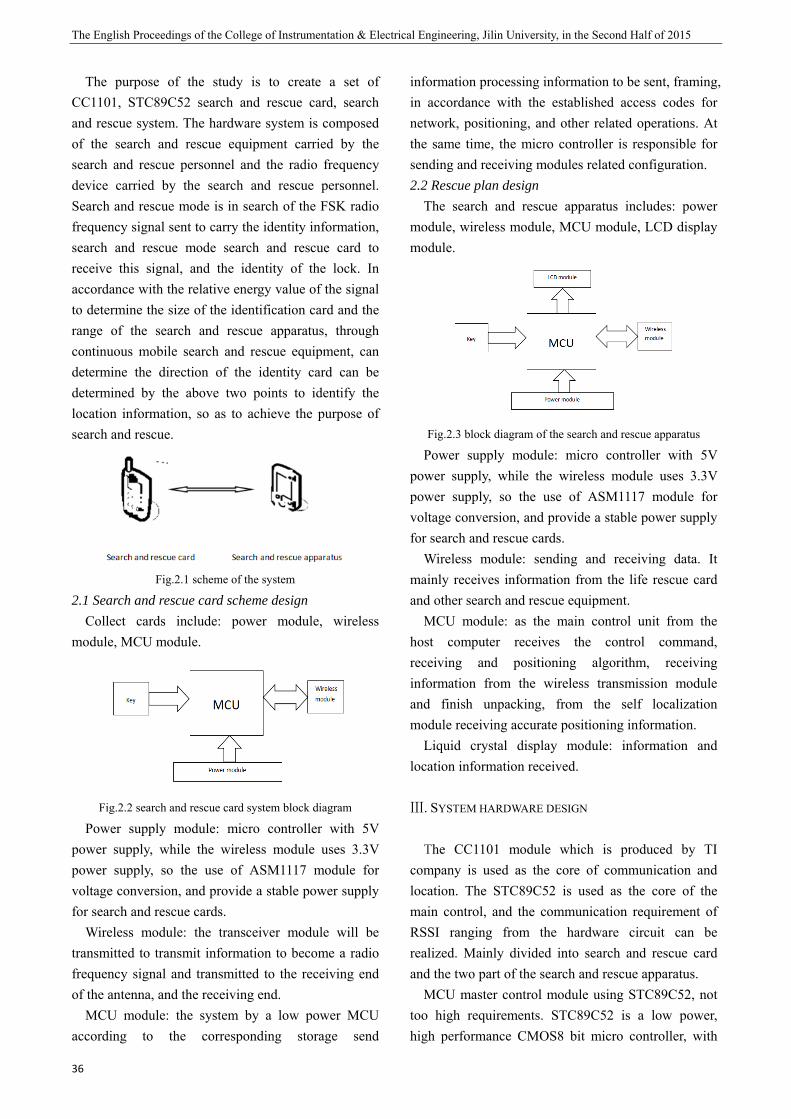
The English Proceedings of the College of Instrumentation & Electrical Engineering, Jilin University, in the Second Half of 2015
36
The purpose of the study is to create a set of CC1101, STC89C52 search and rescue card, search and rescue system. The hardware system is composed of the search and rescue equipment carried by the search and rescue personnel and the radio frequency device carried by the search and rescue personnel. Search and rescue mode is in search of the FSK radio frequency signal sent to carry the identity information, search and rescue mode search and rescue card to receive this signal, and the identity of the lock. In accordance with the relative energy value of the signal to determine the size of the identification card and the range of the search and rescue apparatus, through continuous mobile search and rescue equipment, can determine the direction of the identity card can be determined by the above two points to identify the location information, so as to achieve the purpose of search and rescue.
Fig.2.1 scheme of the system
2.1 Search and rescue card scheme design Collect cards include: power module, wireless
module, MCU module.
Fig.2.2 search and rescue card system block diagram
Power supply module: micro controller with 5V power supply, while the wireless module uses 3.3V power supply, so the use of ASM1117 module for voltage conversion, and provide a stable power supply for search and rescue cards.
Wireless module: the transceiver module will be transmitted to transmit information to become a radio frequency signal and transmitted to the receiving end of the antenna, and the receiving end.
MCU module: the system by a low power MCU according to the corresponding storage send
information processing information to be sent, framing, in accordance with the established access codes for network, positioning, and other related operations. At the same time, the micro controller is responsible for sending and receiving modules related configuration. 2.2 Rescue plan design
The search and rescue apparatus includes: power module, wireless module, MCU module, LCD display module.
Fig.2.3 block diagram of the search and rescue apparatus
Power supply module: micro controller with 5V power supply, while the wireless module uses 3.3V power supply, so the use of ASM1117 module for voltage conversion, and provide a stable power supply for search and rescue cards.
Wireless module: sending and receiving data. It mainly receives information from the life rescue card and other search and rescue equipment.
MCU module: as the main control unit from the host computer receives the control command, receiving and positioning algorithm, receiving information from the wireless transmission module and finish unpacking, from the self localization module receiving accurate positioning information.
Liquid crystal display module: information and location information received.
Ⅲ. SYSTEM HARDWARE DESIGN
The CC1101 module which is produced by TI company is used as the core of communication and location. The STC89C52 is used as the core of the main control, and the communication requirement of RSSI ranging from the hardware circuit can be realized. Mainly divided into search and rescue card and the two part of the search and rescue apparatus.
MCU master control module using STC89C52, not too high requirements. STC89C52 is a low power, high performance CMOS8 bit micro controller, with

8K in sySTC89C52 ua lot of imptraditional 5function. Onavailable in provide high many embed
The perfocommunicatithe choice owhole systeminto account power consusensitivity, trequired by tof the chipscheme is bcompany in transmission frequency baUHF transceapplications. ISM of 915Mand SRD (shcan also be eand MHz 40transceiver imodem. Theformats, and performance error correcti3.1 Hardwar
Search andthe main chtransmission wireless mod
ystem progruses the classprovements
51 micro con one chip,
the systemh flexibility andded control aormance of Rion performanof the RF chm. The followwhen selectin
umption, distathe number the transmitt
p. The commbased on the
the CC110chip which
and. CC1100 eiver design
Circuits areMHz (industhort range deeasily set to 00-464 of this integrated e modem suits data transcan be impr
ion option onre circuit desigd rescue cardhip, power m
module. Thdule uses CC1
G
rammable Fsic MCS-51 kto make the
ontroller doe8 bit CPU
m, which mand super efficapplications. RF chip dirence of the whhip is very iwing factors ng a wirelessance, transmi
of peripheer and receivmunication me work of th01 module oh is lower is a low cost ed for low e set at 315trial, scientifevices) frequ300-348MHz
he other freqwith a high
upports differsmission rate oved by open
n the modem. gn of search d is made upmodule circuhe main chip1101 wireless
Gao Jiafei etc.: L
Flash memkernel, but me chip with s not have
and Flash akes STC89Ccient solution
ectly affects hole system, important to should be ta transceiver cit power, receral compone
ver, and the cmodule of he Americanof wireless dthan the 1Gtruly monolipower wire
, 433, 868, fic and mediency bands, z, MHz 800-quency. The hly configurarent modulatis 500kbps. T
ning the forw
and rescue cap of three pauit and wirep is STC89Cs module.
Life rescue syst
mory. made
the the are
C52 n for
the and the
aken chip: eive ents cost this
n TI data GHz ithic eless
and ical) and
-928 RF
able ation The
ward
ard arts: eless C51,
Ato cfor and3.2 app
TparttranmaiCCLCD
Trespand
tem based on C
Fig.3.1 sear
A set of data carry out thethe RSSI ev
d STC89C52 Hardware
paratus The search ants: the main nsmission moin chip is 1101 wirelD12864.
Fig.3.2 s
The search ponsible for rd the RSSI v
CC1101
ch and rescue c
is fixed by the identificatiovaluation. Macomposition.circuit desig
nd rescue appchip, the powodule and thSTC89C51,
ess module
search and resc
and rescuereceiving the value of the
card schematic
he search andon and rescuainly by CC. gn of search
paratus is madwer module,
the display m wireless m
e. Display
cue hardware ci
e instrumendata from thchannel is r
37
diagram
d rescue cardue instrument1101 module
h and rescue
de up of four the wirelessmodule. Themodule uses
module is
rcuit
nt is partlyhe rescue cardread, and the
7
d t e
e
r s e s s
y d, e

The English Pr
38
correspondinwhich is disp
Ⅳ. POSITION
In wirelesscritical to thlocation of this the impornetwork nodand ultrasonihardware coinfrared rangerror is 1cmbased on RSreceived wirRSSI. The m4.1 Distance
The princithe distance intensity of function to aRSSI value icurrent changain setting levels in thintensity of between the the corresponscheme usesestimation, asignal is coSearch and rthe location rescue. Work
roceedings of th
ng software iplayed in 128
NING SYSTEM
s sensor netwhe monitorinhe event or thrtant informade monitorinic ranging req
ost and size ge error, and
m, but the temSSI, it can nreless signal
method is basemeasuremen
iple of distanbetween a p
f the receiveachieve throuis an assessmnnel. This vain the RX ch
he channel. the receivedtransmissionnding data tos this methand the diffeonverted intorescue accordand the fin
king principle
he College of In
is converted 64.
DESIGN
works, locationg of sensorhe location ofation containeg informatioquire additionof the nodethe use of ul
mperature andnot be used intensity, wh
ed on RSSI. nt based on RSnce measuremperson and aed signal. Hugh the C110
ment of the sialue is basedhain and the RSSI is to
d signal to gn point, and tho locate the thod to obtaiferent intensio different dding to the dal search to
e is shown in
nstrumentation &
into a distan
on informatior networks, f the informated in the senon.GPS, infranal hardware,s, the GPS ltrasonic rangd humidity, eto calculate
hich is based
SSI ment is to refa person by Here the R01 RF chip. gnal level in
d on the currmeasured sig determine get the distahen accordingtechnology. Tin the distaity of the Rdistance valu
distance betwthe search
figure 2.
& Electrical En
nce,
on is the
tion nsor ared , the and
ging etc., the
d on
flect the
RSSI The
n the rrent gnal the
ance g to This ance
RSSI ues.
ween and
Itthe betw
Ⅴ.
5.1 T
in fwhiand
OTab
D
Itbetwis a
ngineering, Jilin
Fig.4.1
t can be seenchange of d
ween the dist
SYSTEM TEST
EnvironmentThe actual tesfront of the ich was not d
d the strong elOn the grass:ble 5.1. The vari
istance
(m)
Num
RS
(db
1
2
3
4
5
6
7
8
9
10
11
t can be seween the grasa certain relat
n University, in
1 RSSI and dist
n that the valdistance, thereance and the
T
tal impact on sts were carriopen square
disturbed by tlectromagneti
iation of RSSI w
of the gr
mber 1
SSI
bm)
-29
-34
-41
-48
-42
-43
-44
-50
-50
-50
-50
een that the ss on the RSStionship betw
the Second Ha
tance fitting cur
lue of RSSI e is a certainRSSI value.
n RSSI ranginied out in the
in front of the grass, thetic interferenc
with distance fr
rass.
2
-30
-33
-42
-44
-41
-44
-44
-44
-43
-43
-44
change of SI value will ween the dist
alf of 2015
rve
changes withn relationship
g e open squarethe building,
e narrow aislece.
rom the surface
3 4
-27 -31
-30 -35
-37 -42
-38 -43
-38 -38
-38 -40
-38 -42
-40 -44
-41 -50
-43 -49
-43 -50
the distancechange, theretance and the
h p
e , e
e
e e e

Gao Jiafei etc.: Life rescue system based on CC1101
39
RSSI value. Narrow aisle:
Table5.2 narrow aisle RSSI vary with distance
Distance
(m)
Number 1 2 3
RSSI
(dbm)
1 -32 -32 -32
2 -34 -36 -34
3 -44 -48 -48
4 -49 -50 -50
5 -42 -48 -49
6 -40 -41 -50
7 -41 -42 -50
8 -41 -44 -50
9 -42 -43 -56
10 -43 -44 -55
11 -50 -49 -58
In the narrow aisle, because of the reflection of obstacles and other factors, the RSSI value of the change has occurred in the chaos, the law is not very obvious.
Strong electromagnetic interference in the front of the palace of the geological Palace square:
Table5.3 The RSSI varies with distance from the front of the
house
Distance
(m)
Number 1 2
RSSI
(dbm)
1 -38 -40
2 -36 -50
3 -41 -49
4 -54 -57
5 -43 -50
6 -43 -62
7 -44 -56
8 -44 -54
9 -44 -59
10 -42 -59
In front of the geological palace due to strong electromagnetic interference RSSI value has been very serious confusion, it is difficult to see the law.
After the actual test, it can be seen that the interference in the narrow aisle and the front of the palace is very serious, especially in front of the geological palace. According to the measured values
in the grassland, 1M, 2m, 3M, 10m four nodes are fixed. Node selection: Table 5.4 the change of RSSI with distance in front of grassland
Dista
nce
(m)
Number 1 2 3 4 5
RSSI
(dbm)
1 -32 -30 -28 -28 -26
2 -35 -33 -31 -30 -30
3 -39 -40 -37 -38 -36
10 -48 -49 -43 -42 -41
According to the experimental results, the range of the RSSI value of the appropriate node is selected to complete the ranging work.
Ⅵ. CONCLUSION
In this paper, a set of life search and rescue system based on CC1101 chip is designed. The system mainly includes two parts, search and rescue card and rescue instrument. The hardware system is based on the STC89C52 micro controller, wireless RF transceiver chip CC1101 as the core component. After many experiments, the results show that the design system has good working performance, which is beneficial to the search and rescue people clearly the identity information and the specific location of the trapped people. Although the environmental interference is relatively large, but can be determined by constantly moving roughly the location of the search and rescue, can play a role in the rescue. In the future work, we can do further research on the environmental factors under complex conditions.
References
[1] Guo Hui, Fu Chenghua, Wu Hao. Based on PLC nRF2401
wireless communication controller [J]. electronic design
engineering, 2010 (3): 113 -115.
[2] Wu Dongmiao. RF data acquisition system and its
application [J]. coal technology, 2005 (7): 23 -25.
[3] Yue Yang, Huang Ming. Based on nRF9E5 design and
implementation of wireless data acquisition and

The English Proceedings of the College of Instrumentation & Electrical Engineering, Jilin University, in the Second Half of 2015
40
monitoring system [J]. electronic measurement technology,
2009 (10); 129 -132.
XIE Yantong etc.: Design of intelligent guide rod based on the infrared alarm
41
Design of intelligent guide rod based on the infrared alarm
XIE Yantong; CUI Yuqi; DENG Qitian
(Department of Instrument,Jilin University,Changchun,130022)
Abstract-Based on triangle ranging principle of infrared detector and photoelectric sensing technology, design a new kind
of intelligent guide system. This guide system with the mega32 controller as the core, three directions of infrared distance
sensors to collect all round the distance of the obstacle information, through a certain algorithm program, the system reads
around the distance and the direction of the obstacles making a judgment to alarm the user or not. The double voice alarm
system control buzzer and MP3 module,which helps the users determine the direction of walking. This design improves the
infrared alarm timeliness and accuracy, so as to guide the blind avoid obstacles and guarantee the safety of walking.
Key words-Infrared detector Mega32 controller Guide rod Voice alarm
I.INTRODUCTION
NOW there are about 5000000 blind people in China, the world's total number of blind 18%. The blind walking alone in with great difficulty, now guide blind methods mainly the following three: (1) the traditional blind guiding walking stick; (2) using blind guide, (3) using a guide dog guide. The traditional blind guiding walking stick guide blind by hitting the ground to judge whether the can pass in front of, but can not let the blind on around the barrier distribution and and obstacles of distance [1] make judgment; guided in the guide, there are some limitations of the blind; guide dog training cycle is very long, and the cost is relatively high [2].Therefore, this paper presents a guide a blind person walking improved scheme, simultaneous measurement of the front, the left and right-hand obstacle distance information by using three infrared sensors, microcontroller using specific algorithm to judge the preliminary treatment and safety of income data. After using MP3 voice module issued prompt tone and buzzer buzzing alarm to notify the blind around the obstacle distance, through this method expanded the sensing range of the blind, to improve the security of the blind to walk alone.
1 SYSTEM WORKING PRINCIPLE
1.1 Infrared detector ranging principle
The guide system, to measure its distance and obstacle using infrared sensor. The infrared sensor is using triangulation principle to measure the distance between itself and the obstacle, the measured barriers should be reflector with a diffuse reflectance properties, such as paper, walls and other [3][4][5]. The basic principle of triangulation method is the use of plane triangulation. The three vertices of the triangle are obstacles, infrared emission end and an infrared receiver, an infrared transmitting end to a certain angle theta emitted infrared light, when faced with obstacles, the light will be reflected back, the reflected light will exposure to infrared receiving end of CCD detection device, CCD detector relative to the center position will have an offset x, offset size will change d with the distance between infrared detector and obstacles and change. After using the trigonometric function, using infrared emission angle theta, offset x, filter the focal length f, moment D, through the geometric relationship can be the obstacle sensors and the distance D calculated [6], figure 1.1 is schematic diagram of planar triangulation principle.
Common infrared sensor structure is fixed, infrared emission angle theta, lens focal length f, center matrix D is constant, so obstacle sensors and the distance d only by reflecting light in the infrared receiving end of CCD detector offset x [7]. There is a certain proportional relationship between the analog output voltage signal and the offset X of the infrared sensor, which is a function relationship

The English Proceedings of the College of Instrumentation & Electrical Engineering, Jilin University, in the Second Half of 2015
42
between the analog output voltage signal and the distance D.
Fig.1.1 The principle diagram of the triangulation ranging
1.2 Sensor simulation output is transformed to the distance output function fitting
In the actual measurement, the infrared sensor output is analog voltage, but in practical programming need to know is the actual distance, so to get the actual distance and the corresponding relationship between the analog voltage. Using infrared sensor to measure the distance between the obstacles and the distance of the fixed distance, the output of the analog voltage and the distance of the obstacle distance, the proportion of the relationship between the two, the function relationship between the [7]. Figure 1.2 describes the corresponding relationship between the analog voltage U and the D of the distance measured by the infrared sensor output. Assuming that the actual obstacle distance and the output analog voltage in accordance with the following relations:
kbU
mD −+
= (1),
type (1), m, B, K are constants, and the deformation is obtained:
mb
mU
D+=
+ k1
(2),
kD +1
and U with a positive ratio, figure 1.3
depicts a functional relationship of kD +1
and
U (order 41=m
).
Fig.1.2 Actual obstacle distance and the detector output
analog voltage value corresponding curve
Fig.1.3 The Fitting curve of kD +1
and U
The Slope calculated by MATLAB is 3101472.01 −×=
m ,intercept
310412.0 −×−=mb
,we can calculate
6793=m , 8.2−=b .Finally, the function
relationship of D andU is 4
8.26793
−−
=U
D.After
comparison, the results of this study are basically consistent with the calculation of the calculated results.
2 SYSTEM HARDWARE DESIGN
The guide system mainly consists of three modules, respectively, for infrared ranging module, the signal processing control module, a voice alarm module, as shown in Figure 2.1. Mega32 microcontroller as the control core of the system, SHARP GP2Y0A02YK0F sensor as the infrared distance sensor, MP3-VS1003B voice chip as the main chip of voice alarm module. 2.1 Infrared ranging module
Infrared distance measuring module of SHARP GP2Y0A02YK0F infrared distance sensor, the

XIE Yantong etc.: Design of intelligent guide rod based on the infrared alarm
43
measurement range is 20~150cm. SHARP GP2Y0A02YK0F infrared distance sensor is mainly composed of the infrared emission, infrared receiver and corresponding processing calculation circuit. The infrared transmitting and receiving end of the infrared receiving end and the obstacle which is measured constitute a plane triangle, as shown in figure 2.2. The distance between the original and the human is calculated by the triangle method which is introduced above.
Fig.2.1 The overall design of the system
2.2 Signal processing control module The signal processing control module flow is
shown in Figure 2.3, the mega32 microcontroller as the control system of the main control chip, which has a digital port and analog port, which is used to receive infrared detector analog output voltage value, the input to the A/D link conversion to digital quantity, that is converted to actual obstacle distance, and then according to the actual obstacle distance to determine whether it is in the safe range, then voice alarm chip will generate the corresponding alarm.
Fig.2.2 The infrared transmitting and receiving
Fig.2.3 The control system work flow chart
2.3 Voice alarm module Using the VS1003B chip as a voice alarm
decoder, VS1003B can support the audio data required to read from the external RAM.
The recorded audio clips are converted into 16 binary code, the code is stored in the external memory, the current distance is less than the default security distance, the software controls the voice decoding, the voice through the headset to play out, to achieve the alarm. 2.4 vibration alarm module
Using the micro vibration motor as vibration alarm unit, using the single chip pin to control, using NPN tube 9013 to drive, vibration motor in the left and right sides of the walking stick, representing different directions, when the distance is less than the default security distance, the vibration alarm.
3 SYSTEM SOFTWARE DESIGN
3.1 Instrument software design The system uses mega32 microcontroller C
language programming, the need for SHARP GP2Y0A02YK0F infrared distance sensor, AD0809, 1602 LCD, etc.. The overall program consists of infrared ranging module, signal processing control module and voice alarm module, as shown in figure 3.1.
Fig.3.1 The overall program flow chart
3.2 Optimal operation method
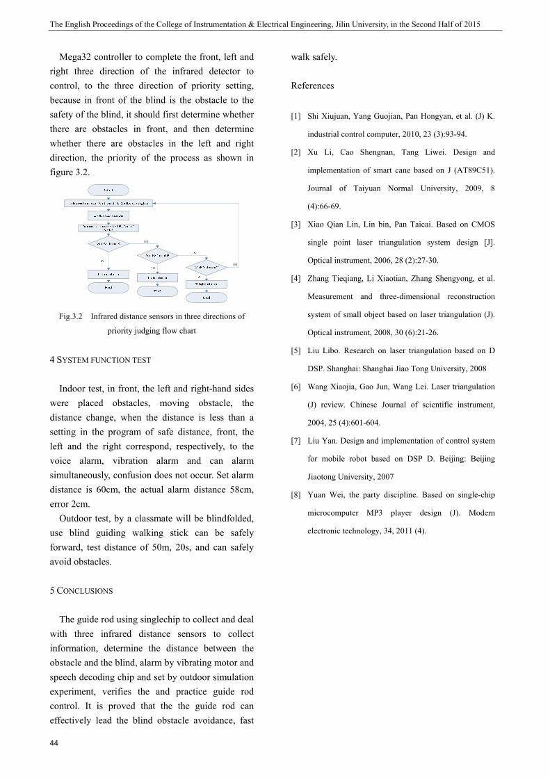
The English Proceedings of the College of Instrumentation & Electrical Engineering, Jilin University, in the Second Half of 2015
44
Mega32 controller to complete the front, left and right three direction of the infrared detector to control, to the three direction of priority setting, because in front of the blind is the obstacle to the safety of the blind, it should first determine whether there are obstacles in front, and then determine whether there are obstacles in the left and right direction, the priority of the process as shown in figure 3.2.
Fig.3.2 Infrared distance sensors in three directions of
priority judging flow chart
4 SYSTEM FUNCTION TEST
Indoor test, in front, the left and right-hand sides were placed obstacles, moving obstacle, the distance change, when the distance is less than a setting in the program of safe distance, front, the left and the right correspond, respectively, to the voice alarm, vibration alarm and can alarm simultaneously, confusion does not occur. Set alarm distance is 60cm, the actual alarm distance 58cm, error 2cm.
Outdoor test, by a classmate will be blindfolded, use blind guiding walking stick can be safely forward, test distance of 50m, 20s, and can safely avoid obstacles.
5 CONCLUSIONS
The guide rod using singlechip to collect and deal with three infrared distance sensors to collect information, determine the distance between the obstacle and the blind, alarm by vibrating motor and speech decoding chip and set by outdoor simulation experiment, verifies the and practice guide rod control. It is proved that the the guide rod can effectively lead the blind obstacle avoidance, fast
walk safely.
References
[1] Shi Xiujuan, Yang Guojian, Pan Hongyan, et al. (J) K.
industrial control computer, 2010, 23 (3):93-94.
[2] Xu Li, Cao Shengnan, Tang Liwei. Design and
implementation of smart cane based on J (AT89C51).
Journal of Taiyuan Normal University, 2009, 8
(4):66-69.
[3] Xiao Qian Lin, Lin bin, Pan Taicai. Based on CMOS
single point laser triangulation system design [J].
Optical instrument, 2006, 28 (2):27-30.
[4] Zhang Tieqiang, Li Xiaotian, Zhang Shengyong, et al.
Measurement and three-dimensional reconstruction
system of small object based on laser triangulation (J).
Optical instrument, 2008, 30 (6):21-26.
[5] Liu Libo. Research on laser triangulation based on D
DSP. Shanghai: Shanghai Jiao Tong University, 2008
[6] Wang Xiaojia, Gao Jun, Wang Lei. Laser triangulation
(J) review. Chinese Journal of scientific instrument,
2004, 25 (4):601-604.
[7] Liu Yan. Design and implementation of control system
for mobile robot based on DSP D. Beijing: Beijing
Jiaotong University, 2007
[8] Yuan Wei, the party discipline. Based on single-chip
microcomputer MP3 player design (J). Modern
electronic technology, 34, 2011 (4).
A
Zhourui etc.: D
Dmo
Abstract-In
of movement a
android techn
the android pl
injury and ph
acceleration o
parameters of
the human bo
human body
monitoring an
I. INTRODUCT
EXCESSIVE eathletic and agility and bsevere cases damage anacceleration which can buof human mcorrect the effectively, efficiency, pexercise.Appfrom falling devaluate exechronic disea
II . THE M
MOTION INFO
A. Modelin The steps
one second
Design and impl
Design onitor
s
(Jilin uni
order to avoid
and race, the a
nology to moni
latform to calc
hysical overdra
of the human
f acceleration,
ody can be trac
motion and
nd tracking, pr
TION
exercise and uhealthy exer
balances of hthey can lead
nd other sensor comb
uild sports mmovement effe
non-standardoptimize
prevent spoplies to exercdown effectiv
ercise of theiases and obes
MATHEMATICA
ORMATION
ng about consper second n
/(1101 mtavv ×+=
lementation of
and iming syensor
Civersity instru
d the damages
article propose
tor the real-tim
culate calories
aft. Adoption m
n body can be
speed, mileag
cked and posit
prejudge dan
rotect of health
uncorrected arcise cause thuman are od to muscle apermanent
bines the Anmodel and refl
ectively and d athletic stsports trairts injuries
cise, it can pvely, and provir own for thsity.
AL MODELING
suming energyn:the body spe
)/sm ,mileage
a movement m
mplemstem band a
Caijing; Zhoument science
to the body th
s the design of
me parameters
consume and
msp430 microp
e measured b
ge and consum
tioned.Through
gerous action
h of exercisers.
athletic stanchat the phys
on the declinatrophy, cartil
injuries.pretndroid platfolect the situatfully.It can a
tance of athining, impr
and excessprevent the elvide a methohe patients w
G ANALYSIS
y eed at the end
in one sec
monitoring system
mentatbased ndroid
ourui; Tianrue and enginee
hat owing to th
f a movement m
s and postures
d evaluate mod
processor as c
by using mpu
mption of calor
h the identific
n. Experimenta
e in sical ne,in lage trial
orm, ation also
hlete rove sive lder d to with
OF
d of
cond
1x =
0.35
Aonelengstep
TA
Etota
=W
wei
TAB
B. iB
m based on the
tion ofon thed techuyun; Liuleering institute
he incorrect po
monitoring sys
s of the human
deling of the m
ontroller of th
6050 three-ax
ies in the mov
ation algorithm
al results sho
21110 2
1 tatv ××+×
5m,so steps p
Average speee second is obgth .The relatps per second
n 1
m h*5
ABLE 1 THE RELA
Energy consual calorie
5.41
1 ××=∑=
n
iVw
ight.
BLE 2 RELATIO
identification Based on thr
human body se
f a move humnology
ei e,Changchun,
ostures and exc
stem based on
n body in the p
movement postu
he monitoring
xis acceleration
vement can be
m of human bo
w, system can
(m),A step
per second:n =
ed in movembtained by V
tionship betwd is shown in T
2 3
h*4 h*3
ATIONSHIP BETW
STEPS PER S
umption W :Des consum
1800÷iV ,w1
ONSHIP BETWEEN
CONSUMP
of human moree axis acce
ensor and andro
vemenman bod
y
,130021)
xcess exercises
the human bo
process of mov
ure in order to
system, three
n sensor.More
detected. The
ody posture, it
n realize real
p size for ad
35.01x
=.
ment V :AveraV = steps per ween stride leTable 1.
4 5
h*2 h*2
WEEN STRIDE LEN
SECOND
Derived frommed in
(Kg) for th
N AVERAGE SPEE
PTION
otion model elerometer c
oid technoology
45
nt dy
in the process
dy sensor and
vement. Using
o avoid sports
axis (X, Y, Z)
eover, motion
e trajectory of
t can evaluate
l-time motion
dults is about
age speed insecond× step
ength and the
6 >6
h*1 h*0.
5
NGTH AND THE
m table 2 theN is:
he individual
ED AND ENERGY
calibration of
y
5
f
t
n p e
e :
l
f
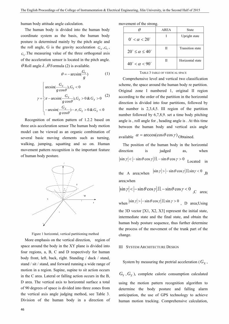
The English Proceedings of the College of Instrumentation & Electrical Engineering, Jilin University, in the Second Half of 2015
46
human body attitude angle calculation. The human body is divided into the human body
coordinate system as the basis, the human body posture is determined mainly by the pitch angle and the roll angle, G is the gravity acceleration XG ,
YG ,
ZG .The measuring value of the three orthogonal axis of the acceleration sensor is located in the pitch angle.θ Roll angleλ ,θ Formula (2) is available.
)arcsin(g
GY−=θ (1)
⎪⎪⎪
⎩
⎪⎪⎪
⎨
⎧
<>−−
>>−
<
=
0&0,)cos
arcsin(
0&0),cos
arcsin(
0),cos
arcsin(
XZX
XZX
ZX
GGg
G
GGg
G
Gg
G
πθ
θπ
θ
γ(2)
Recognition of motion pattern of 1.2.2 based on three axis acceleration sensor The human body motion model can be viewed as an organic combination of several basic moving elements such as turning, walking, jumping, squatting and so on. Human movement pattern recognition is the important feature of human body posture.
Figure 1 horizontal, vertical partitioning method
More emphasis on the vertical direction, region of space around the body in the XY plane is divided into four regions, a, B, C and D respectively for human body front, left, back, right. Standing / duck / stand, stand / sit / stand, and forward running a wide range of motion in a region. Supine, supine to sit action occurs in the C area. Lateral or falling action occurs in the B, D area. The vertical axis to horizontal surface a total of 90 degrees of space is divided into three zones from the vertical axis angle judging method, see Table 3. Division of the human body in a direction of
movement of the strong. θ AREA State
oo 200 <<α I Upright state
oo 4020 ≤≤αII Transition state
oo 9040 <<αII Horizontal state
TABLE 3 TABLE OF VERTICAL SPACE
Comprehensive level and vertical two classification scheme, the space around the human body re partition. Original zone I numbered 1, original II region according to the order of the partition in the horizontal direction is divided into four partitions, followed by the number is 2,3,4,5. III region of the partition number followed by 6,7,8,9. set a time body pitching angle is , roll angle for , heading angle is . At this time between the human body and vertical axis angle
available )cosarccos(cos γθα = Obtained.
The position of the human body in the horizontal direction is judged as, when
0cossincossinsin >−−< γθγθγ 且 Located in
the A area;when 0sincossinsin <−> γγθγ 且 ,B
area;when
0cossincossinsin <−−< γθγθγ 且,C area;
when 0sincossinsin >−> γγθγ 且 , D area;Using
the 3D vector [X1, X2, X3] represent the initial state, intermediate state and the final state, and obtain the human body posture sequence, thus further determine the process of the movement of the trunk part of the change.
III SYSTEM ARCHITECTURE DESIGN
System by measuring the pretrial acceleration ( XG ,
YG , ZG ), complete calorie consumption calculated
using the motion pattern recognition algorithm to determine the body posture and falling alarm anticipation, the use of GPS technology to achieve human motion tracking. Comprehensive calculation,
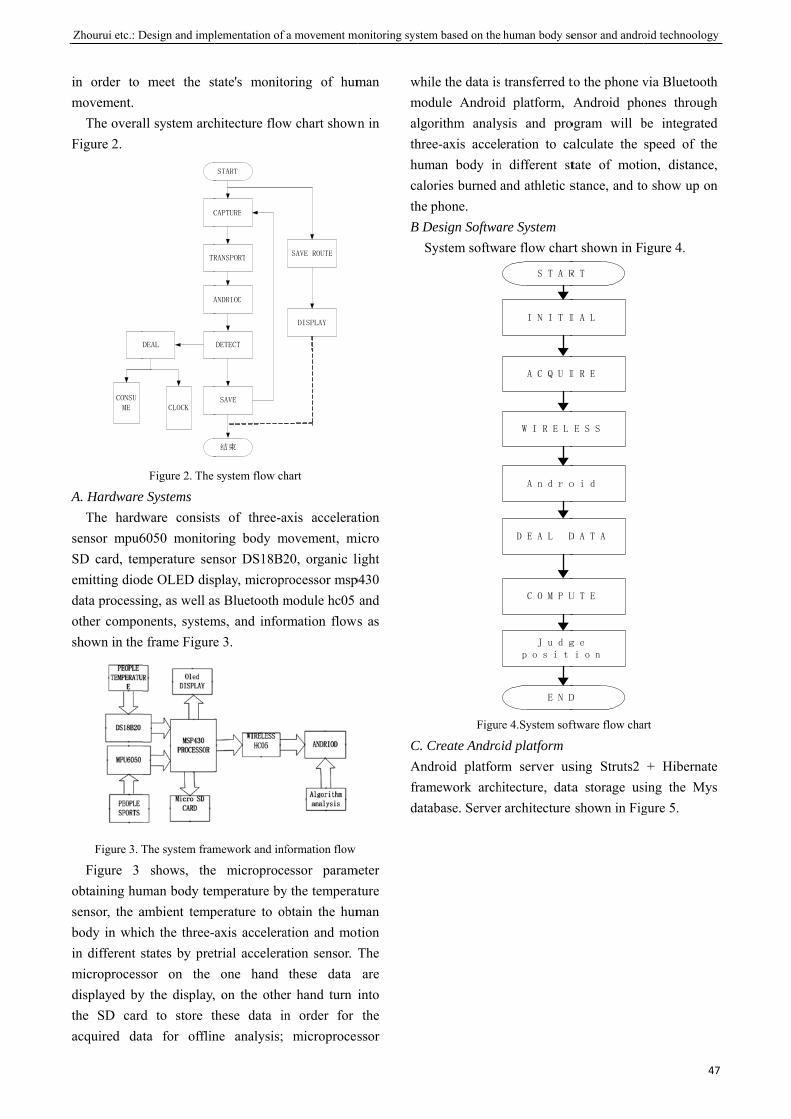
A
Zhourui etc.: D
in order to movement.
The overalFigure 2.
D
CONSU
ME
A. HardwareThe hardw
sensor mpu6SD card, tememitting dioddata processiother composhown in the
Figure 3. T
Figure 3 obtaining humsensor, the abody in whicin different smicroprocessdisplayed bythe SD cardacquired dat
Design and impl
meet the st
ll system arch
C
DEAL
CLOCK
TR
A
Figure 2. The
e Systems ware consist6050 monitormperature sende OLED disping, as well a
onents, system frame Figure
The system fram
shows, theman body tem
ambient tempch the three-states by pretsor on the y the display,d to store tta for offlin
lementation of
tate's monito
hitecture flow
START
CAPTURE
DETECT
SAVE
结束
RANSPORT
ANDRIOD
system flow ch
ts of three-aring body mnsor DS18B2play, micropr
as Bluetooth mms, and infore 3.
mework and inf
e microprocemperature byperature to obaxis acceleratrial acceleraone hand
, on the othethese data inne analysis;
a movement m
oring of hum
w chart shown
SAVE ROUTE
DISPLAY
hart
axis acceleratmovement, mi20, organic lirocessor mspmodule hc05 rmation flows
formation flow
essor paramy the temperatbtain the hum
ation and motation sensor. T
these data er hand turn in order for
microproces
monitoring system
man
n in
ation micro
ight p430
and s as
meter ature man tion The are
into the
ssor
whimodalgothrehumcalothe B D
S
C. CAndframdata
m based on the
ile the data isdule Androidorithm analyee-axis accelman body inories burned phone.
Design SoftwaSystem softwa
Figur
Create Androdroid platformework archabase. Server
human body se
transferred td platform, ysis and proeration to ca
n different stand athletic s
are System are flow char
S T A R
I N I T I
E N D
A C Q U I
W I R E L
A n d r o
D E A L D
C O M P U
J u d gp o s i t
re 4.System sof
id platform rm server ushitecture, datar architecture
ensor and andro
to the phone vAndroid pho
ogram will balculate the tate of motistance, and to
rt shown in F
R T
I A L
D
I R E
E S S
o i d
D A T A
U T E
g e i o n
ftware flow cha
sing Struts2 a storage usshown in Fig
oid technoology
47
via Bluetoothones throughbe integratedspeed of theon, distance,o show up on
igure 4.
art
+ Hibernatesing the Mysgure 5.
y
7
h h d e ,
n
e s
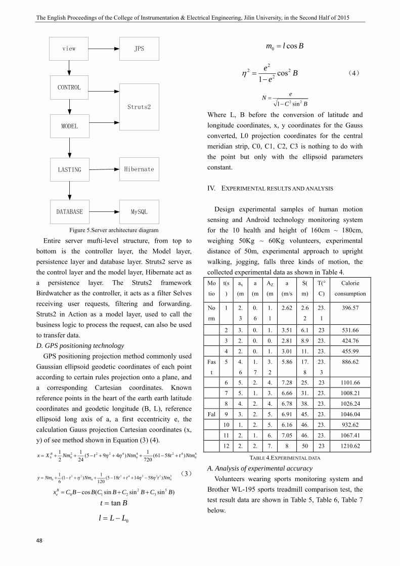
The English Proceedings of the College of Instrumentation & Electrical Engineering, Jilin University, in the Second Half of 2015
48
view
CONTROL
MODEL
LASTING
DATABASE
JPS
Struts2
Hibernate
MySQL
Figure 5.Server architecture diagram
Entire server mufti-level structure, from top to bottom is the controller layer, the Model layer, persistence layer and database layer. Struts2 serve as the control layer and the model layer, Hibernate act as a persistence layer. The Struts2 framework Birdwatcher as the controller, it acts as a filter Selves receiving user requests, filtering and forwarding. Struts2 in Action as a model layer, used to call the business logic to process the request, can also be used to transfer data. D. GPS positioning technology
GPS positioning projection method commonly used Gaussian ellipsoid geodetic coordinates of each point according to certain rules projection onto a plane, and a corresponding Cartesian coordinates. Known reference points in the heart of the earth earth latitude coordinates and geodetic longitude (B, L), reference ellipsoid long axis of a, a first eccentricity e, the calculation Gauss projection Cartesian coordinates (x, y) of see method shown in Equation (3) (4).
60
4240
422200 )5861(
7201)495(
241
21 NtmttNtmtNmXx B +−+++−++= ηη
50
222420
220 )5814185(
1201)1(
61 NmtttNmtNmy ηηη −++−++−+=
(3)
)sinsinsin(cos 53
2210 BCBCBCBBCxB
e ++−=
Bt tan=
0LLl −=
Blm cos0 =
Be
e 22
22 cos
1−=η (4)
BCeN
22 sin1−=
Where L, B before the conversion of latitude and longitude coordinates, x, y coordinates for the Gauss converted, L0 projection coordinates for the central meridian strip, C0, C1, C2, C3 is nothing to do with the point but only with the ellipsoid parameters constant.
IV. EXPERIMENTAL RESULTS AND ANALYSIS
Design experimental samples of human motion sensing and Android technology monitoring system for the 10 health and height of 160cm ~ 180cm, weighing 50Kg ~ 60Kg volunteers, experimental distance of 50m, experimental approach to upright walking, jogging, falls three kinds of motion, the collected experimental data as shown in Table 4. Mo
tio
t(s
)
ax
(m
/ 2
a
(m
/ 2
AZ
(m
/ 2
a
(m/s
2)
S(
m)
T(°
C)
Calorie
consumption
(C)No
rm
1 2.
3
0.
6
1.
1
2.62 2.6
2
23.
1
396.57
2 3. 0. 1. 3.51 6.1 23 531.66
3 2. 0. 0. 2.81 8.9 23. 424.76
4 2. 0. 1. 3.01 11. 23. 455.99
Fas
t
5 4.
6
1.
7
3.
2
5.86 17.
8
23.
3
886.62
6 5. 2. 4. 7.28 25. 23 1101.66
7 5. 1. 3. 6.66 31. 23. 1008.21
8 4. 2. 4. 6.78 38. 23. 1026.24
Fal 9 3. 2. 5. 6.91 45. 23. 1046.04
10 1. 2. 5. 6.16 46. 23. 932.62
11 2. 1. 6. 7.05 46. 23. 1067.41
12 2. 2. 7. 8 50 23 1210.62
TABLE 4.EXPERIMENTAL DATA
A. Analysis of experimental accuracy Volunteers wearing sports monitoring system and
Brother WL-195 sports treadmill comparison test, the test result data are shown in Table 5, Table 6, Table 7 below.
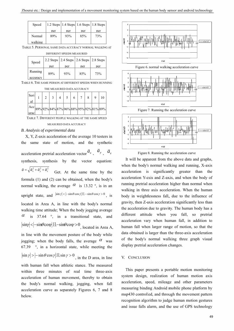
B
j
Zhourui etc.: D
Speed
Normal
walkingTABLE 5. PERSO
Speed
Running
accuracy TABLE 6. THE S
Seri
al 1
Acc
urac89%
TABLE 7. D
B. Analysis ofX, Y, Z-ax
the same
acceleration p
synthesis,
22yx aaa vvv ++=
formula (1) anormal walk
upright state
located in Awalking timeα is 37.
sinsin −< θγ
in line with jogging; wh67.39 °, in
sinsin −>γ
with human within threacceleration the body's acceleration below.
Design and impl
1.2 Steps
per
1
g
89%
ONAL SAME DAT
DIFFERENT SP
2.2 Steps
per
2.4
89%
AME PERSON AT
THE MEASURE
2 3 4
92% 84% 87%
IFFERENT PEOPL
MEASURED D
of experimentxis acceleratiostate of m
pretrial accel
synthesis b
2zav+ Get.
and (2) can bking, the aver
e, and sin <γ
Area A, in le attitude; Wh64 °, in
sincos −γθ 且
the movemenen the bodyn a horizont
sincosn γθ 且
fall when atee minutes
of human mnormal wacurve as sep
lementation of
.4 Steps
per
1.6 St
per93% 85%
TA ACCURACY NO
PEEDS MEASURE
4 Steps
per
2.6 St
per
93% 85%
T DIFFERENT SPEE
D DATA ACCURA
5 6 7
96% 88% 95%
LE WALKING AT T
DATA ACCURACY
tal data on of the avermotion, and
leration vecto
by the ve
At the sam
be obtained, rage α is 1
cossin−< γθ 且
line with thehen the body a transition
0cosn >γθ , lo
nt posture ofy falls, the atal state, wh
0n >γ , in th
thletic stanceof real t
movement, thalking, joggiparately Figu
a movement m
teps
r
1.8 Steps
per % 73%
ORMAL WALKING
ED
eps
r
2.8 Steps
per
% 73%
EDS WHEN RUNN
ACY
8 9 10
92% 81% 89%
THE SAME SPEED
Y
rage 10 testerthe synth
or xav、 yav
、
ector equati
me time by
when the bod13.32 °, is in
0cossin >− γθ
e body's norjogging aver
nal state,
ocated in Are
f the body waverage α while meeting
he D area, in
e. The measutime three-ahereby to obing, when ures 6, 7 an
monitoring system
G AT
NING
D
rs in hetic
zav
tion:
the
dy's n an
, is
rmal rage and
ea A,
while was the
line
ured axis
btain fall
nd 8
Iwheaccaccrunwalbodgravthe diffacchumdataof disp
V.
Tsystaccmeamsprecoand
m based on the
Figure 6.
Figure
Figure
t will be appen the body'seleration iseleration Y-aning pretrial lking in threedy in weightlvity, then Z-aacceleration
ferent attitueleration var
man fall whea obtained is the body's
play pretrial a
CONCLUSION
This paper prtem design, eleration, spasuring bindip430 controllognition algo
d issue falls a
human body se
normal walkin
7. Running the
8. Running the
arent from ths normal wals significanaxis and Z-ax
acceleration e axis accelelessness fall,axis acceleratdue to gravit
ude when ry when hum
en larger ranglarger than tnormal walk
acceleration c
N
resents a porrealization
peed, mileagng Android mled, and throuorithm to judgalarm, and th
ensor and andro
ng acceleration
acceleration cu
acceleration cu
he above datalking and runntly greaterxis, and when
higher than eration. Whe, due to the tion significanty. The humayou fall,
man fall, inge of motionthe three-axisking three changes.
rtable motionof human
ge and othermobile phoneugh the movege human mohe use of GP
oid technoology
49
curve
urve
urve
a and graphs,nning, X-axisr than then the body ofnormal whenn the humaninfluence of
ntly less thanan body has a
so pretrialn addition ton, so that thes accelerationgraph visual
n monitoringmotion axis
r parameterse platform byement patternotion gesturesS technology
y
9
, s e f n n f n a l o e n l
g s s y n s y

The English Proceedings of the College of Instrumentation & Electrical Engineering, Jilin University, in the Second Half of 2015
50
for real-time tracking of the movement route. System of motion parameters motion analysis process available calories burned, physical activity assessment body in order to prevent excessive exercise and sports injuries pose a threat to health.
References:
[1] Ming Wu, tension Kali, Li Bi who motor sport attitude
measurement is based on ANN and single-axis
acceleration [J] Sensing Technology, 2011, 24 (6):
923-927
[2] Lu Cue, Fijian Song, Au B, I Li spectrometers different
velocities energy consumption [J] Measurement of Xi'an
Institute of Physical Education, 2013, 30 (1): 104-107
[3] Du Che design proximity sensor electronic pedometer [J]
based on mechanical and electronic, 2014, (1): 80-81
[4] Li Deng, Lu Lake City, Lu would like to wish, Deng
Ganglion, from land-based fall detection Bay MEMS
pretrial acceleration [J] Sensing Technology, 2014, 27 (4):
570-574
[5] yellow cotton wave, Yang Deng, Wang Lei, Chen Inhabit
based on patient motion signal detection system design
and application of wireless sensors [J] Medical Equipment,
2011, 32 (1): 4-7
[6] Thu Guofeng, Wei Haiphong, Pan Min study of human
motion energy detection algorithm based on
three-dimensional acceleration sensor [J] Sensing
Technology, 2001, 24 (8)1217-1222
[7] CAI Thong Jain measuring the amount of human activity
[J] Fuzhou University, 1997, 4
[8] Wang Han IUD Humming, Angelia Chopin simple
measurement of energy consumption for sports and
validity of the method, [J] Physical Sciences, 2013, 32 (6):
69-76
[9] Thu Bi, Zhengzhou Seoul letter, reviewed measurement of
body exercise and consumption of [J] International Journal
of Bio medical Engineering, Volume I, 1997, 17
(4)202-206
[10] Yang Cue single acceleration-based human motion pattern
recognition [D] Guangzhou: South China University of
Technology, 2011
[11] Lee Road, mufti-sensor-based human motion pattern
recognition [D] Shannon: Shannon University, 2010
[12] Zhengzhou based intelligent mobile terminal body
movement monitoring system Design and implementation
of [D] Guangzhou: 66-70South China University of
Technology, 2011
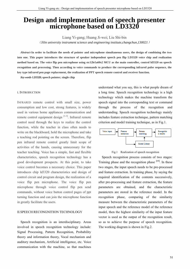
Liang Yi-gang etc.: Design and implementation of speech presenter microphone based on LD3320
51
Design and implementation of speech presenter microphone based on LD3320
Liang Yi-gang; Huang Ji-wei; Liu Shi-bin
(Jilin university instrument science and engineering institute,changchun,130021)
Abstract-In order to facilitate the needs of pointer and microphone simultaneous users, the design of combining the two
into one. This paper introduces the structure of speaker independent speech pen flip LD3320 voice chip and realization
method based on. The voice flip pen microphone using stc12le5a60s2 MCU as the main controller, control ld3320 on speech
recognition and processing. Then according to voice commands to produce the corresponding infrared pulse sequence, the
key type infrared pen page replacement, the realization of PPT speech remote control and receiver function.
Key words- LD3320; speech pointer; single chip
I. INTRODUCTION
INFRARED remote control with small size, power consumption and low cost, strong features, is widely used in various home appliances communication and remote control equipment design [1-3]. Infrared remote control need through the keys to realize the control function, while the teacher in class often needs to write on the blackboard, hold the microphone and take a teaching rod pointing on the screen. Therefore, flip pen infrared remote control greatly limit scope of activities of the hands, causing unnecessary for the teacher teaching. Voice has a simple, fast and flexible characteristics, speech recognition technology has a good development prospects. At this point, to take voice control becomes a necessary choice. This paper introduces chip ld3320 characteristics and design of control circuit and program design, the realization of a voice flip pen microphone. The voice flip pen microphone through voice control flip pen send commands, without voice button control pages of ppt turning function and can join the microphone function in greatly facilitate the users.
II.SPEECH RECONGNITION TECHNOLOGY
Speech recognition is an interdisciplinary. Areas involved in speech recognition technology include: Signal Processing, Pattern Recognition, Probability theory and information theory, Vocal mechanism and auditory mechanism, Artificial intelligence, etc. Voice communication with the machine, so that machines
understand what you say, this is what people dream of a long time. Speech recognition technology is a high technology which makes the machine transform the speech signal into the corresponding text or command through the process of the recognition and understanding. Speech recognition technology mainly includes feature extraction technique, pattern matching criterion and model training technique, as in Fig.1.
Fig.1 Realization of speech recognition
Speech recognition process consists of two stages: Training phase and the recognition phase [4-8]. In these two stages, the input speech needs to be pre-processed and feature extraction. In training phase, by saying the required identification of the contents successively, after pre-processing and feature extraction, the feature parameters are obtained, and the characteristic parameters are stored in the reference model. In the recognition phase, comparing of the similarity measure between the characteristic parameters of the input speech and the reference model of the reference model, then the highest similarity of the input feature vector is used as the output of the recognition result, so as to achieve the purpose of speech recognition. The working diagram is shown in Fig.2.

The English Proceedings of the College of Instrumentation & Electrical Engineering, Jilin University, in the Second Half of 2015
52
Fig.2 Steps for speech recognition
III. THE SYSTEM STRUCTURE
The whole system consists of voice input module, voice processing module, control module and a wireless signal output module, System structure block diagram is shown in Figure 3.
Fig.3 System structure block diagram
At first, the user gives the system speech input signal, then the speech signal will be recognized by voice processing module after pretreatment, and the result of speech recognition will be sent to the control module. Finally, the output signal will control the system working.
IV. STRUCTURE MODULE
A.The Voice Input Module The voice input module gets user speech mainly
through the MIC, then puts it to pin 9, pin 10 and MICN of voice processing module. To improve the system noise immunity, the sound signal can be processed to reduce noise before using. ADC gain can be adjusted by changing the value of the 35 register of LD3320, and the user will achieve the effect he want, The larger value will bring the greater MIC volume and the more sensitive identification starting, but it may bring more erroneous identification; The smaller the value, the smaller the MIC volume is, the recognition function will be started only when you speak closely, the benefit is that the system will not react to the distant voice interference. B. The Voice Processing Module
The function of voice processing module is mainly completed by the LD3320 chip.LD3320 chip is a voice recognition ASIC [9-10].The chip integrates a
speech recognition processor and a number of external circuits,which include ADC、DAC、a microphone interface and voice output interface etc. This chip focus on energy conservation and efficiency in chip design and it does not require any external auxiliary chip such as Flash or RAM and so on. Speech recognition, acoustic control, interactive function can also be achieved, moreover, you can dynamically edit the list of identified key words.
Its features include some points as follows: Highly accurate and practical speech
recognition effect. Keyword list which can be dynamically edited:
you just need to transfer the key word that need identified into the chip as a string, then it can take effect immediately in the next recognition. For example, when you are programming using a single chip, the chip can recognize this setting keyword simply by setting the chip register, just like put identification keyword such as "hello" into the chip.
Allows users to edit 50 keywords freely:at the same time, it can identify during at most 50 keywords. Users can edit and update the contents of this 50 key words at any time according to different requirement. Its chip block diagram is shown in Figure 4. The circuit diagram is shown in Figure 5.
Fig.4 Chip principle block diagram

Liang Yi-gang etc.: Design and implementation of speech presenter microphone based on LD3320
53
Fig.5 LD3320 application circuit diagram
The chip LD3320 uses parallel bus 。
C51_AD0~C51_AD7 connect to P0~P7 of chip LD3320。C51_A8(P2.0)connects to A0 of chip LD3320, A0 is used to distinguish the data segment and addresses segment。Control signal CSB、WRB and RDB are connected to C51_A14(P2.6)、C51_WR(P3.6)、C51_RD(P3.7) separately. C. Master Control Module
The master control module of voice remote control mainly composed by the single chip STC12LE5A60S2. Its working voltage is 3.3V,it has a 8K flash memory and a 512 bits SRAM memory, it also has asynchronous serial interface and 40 I/O interfaces, therefore, this single chip is sufficient to meet the needs of master control system[11]。The master chip circuit diagram is shown in Figure 6.
Fig.6 The master chip circuit diagram
Additionally, by using a wireless remote control circuit to control a switch combination consists of two relays,you can switch between speaker function and speech recognition,so the two working ways run independently, which improves the work efficiency.
V. SOFTWARE PROGRAMMING
The system's speech recognition process is shown in figure 7.
Fig.7 Speech recognition flow chart
First initialize the registers. Mainly complete soft reset, mode setting, clock frequency setting and FIFO setting. Resetting chip is transmitting low level to the chip of the 47 feet (RSTB), then needing to do one time low to high with a chip select CS, to activate the internal DSP.
Second write identification list. Each identification item corresponds to a specific number (1 bytes), and different identification number can be the same, and not continuous. The chip supports up to 50 identification entries, each of which is a standard Mandarin Chinese Pinyin (lowercase), each with a space between 2 words (Chinese Pinyin). Then recognize speech r. and set the value of the register associated with FIFO, MIC, and then carrying out voice recognition.
Finally interrupt response. When the microphone is collected to the sound, regardless of whether the results are normal or not, it will produce an interrupt, which needs to be analyzed. Read the value of the C5 register, the highest score is likely to be the most accurate results. As shown in figure 8.
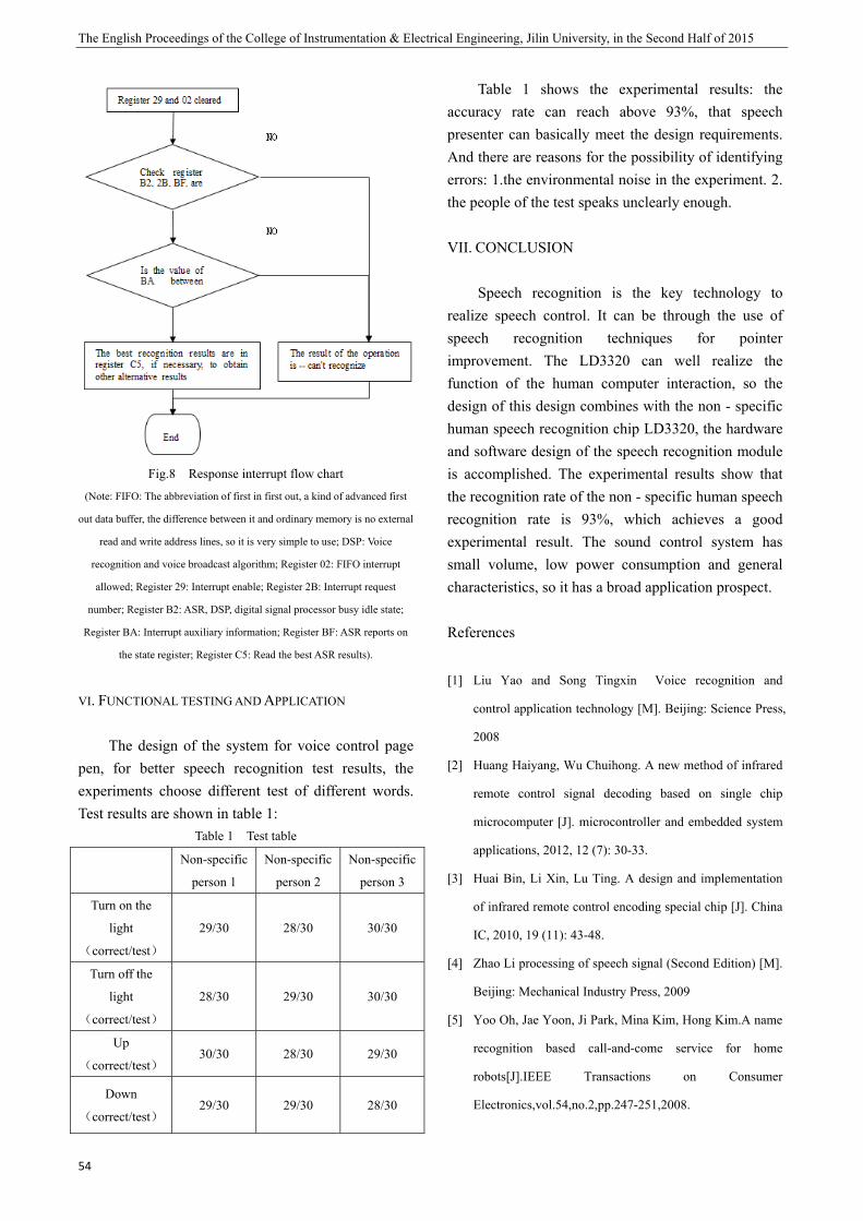
The English Proceedings of the College of Instrumentation & Electrical Engineering, Jilin University, in the Second Half of 2015
54
Fig.8 Response interrupt flow chart
(Note: FIFO: The abbreviation of first in first out, a kind of advanced first
out data buffer, the difference between it and ordinary memory is no external
read and write address lines, so it is very simple to use; DSP: Voice
recognition and voice broadcast algorithm; Register 02: FIFO interrupt
allowed; Register 29: Interrupt enable; Register 2B: Interrupt request
number; Register B2: ASR, DSP, digital signal processor busy idle state;
Register BA: Interrupt auxiliary information; Register BF: ASR reports on
the state register; Register C5: Read the best ASR results).
VI. FUNCTIONAL TESTING AND APPLICATION
The design of the system for voice control page pen, for better speech recognition test results, the experiments choose different test of different words. Test results are shown in table 1:
Table 1 Test table
Non-specific
person 1
Non-specific
person 2
Non-specific
person 3
Turn on the
light
(correct/test)
29/30 28/30 30/30
Turn off the
light
(correct/test)
28/30 29/30 30/30
Up
(correct/test) 30/30 28/30 29/30
Down
(correct/test) 29/30 29/30 28/30
Table 1 shows the experimental results: the accuracy rate can reach above 93%, that speech presenter can basically meet the design requirements. And there are reasons for the possibility of identifying errors: 1.the environmental noise in the experiment. 2. the people of the test speaks unclearly enough.
VII. CONCLUSION
Speech recognition is the key technology to realize speech control. It can be through the use of speech recognition techniques for pointer improvement. The LD3320 can well realize the function of the human computer interaction, so the design of this design combines with the non - specific human speech recognition chip LD3320, the hardware and software design of the speech recognition module is accomplished. The experimental results show that the recognition rate of the non - specific human speech recognition rate is 93%, which achieves a good experimental result. The sound control system has small volume, low power consumption and general characteristics, so it has a broad application prospect.
References
[1] Liu Yao and Song Tingxin Voice recognition and
control application technology [M]. Beijing: Science Press,
2008
[2] Huang Haiyang, Wu Chuihong. A new method of infrared
remote control signal decoding based on single chip
microcomputer [J]. microcontroller and embedded system
applications, 2012, 12 (7): 30-33.
[3] Huai Bin, Li Xin, Lu Ting. A design and implementation
of infrared remote control encoding special chip [J]. China
IC, 2010, 19 (11): 43-48.
[4] Zhao Li processing of speech signal (Second Edition) [M].
Beijing: Mechanical Industry Press, 2009
[5] Yoo Oh, Jae Yoon, Ji Park, Mina Kim, Hong Kim.A name
recognition based call-and-come service for home
robots[J].IEEE Transactions on Consumer
Electronics,vol.54,no.2,pp.247-251,2008.
Liang Yi-gang etc.: Design and implementation of speech presenter microphone based on LD3320
55
[6] Zhang Chenyan, sun was established. The [J]. computer
engineering and application, 196 (13): 194- 2007
[7] Guan Shengping, He Peiyu, Liu Ke, et al.
TMS320VC5509A based speech recognition and control
system [J]. electronic technology applications, 2007 (7):
36- 39
[8] sun Bing. The design of [J]. mechanical engineering and
automation manipulator control system based on MCU,
2007 (6): 113- 117
[9] ICRoute INC.. LD3320 [EB/OL]. development manual
Http://www.icroute.com/doc/LD3320 development
manual. Pdf.
[10] ICRoute INC.. LD3320 [EB/OL].
Http://www.icroute.com/doc/LD3320 data sheet.Pdf.
[11] Ding Xiangrong. STC series of 8051 single-chip
microcomputer principle and application [M]. Beijing:
Electronic Industry Press, 2011.

Wang Haoyu etc.: Portable positioning device for field wiring of electromagnetic field
57
Portable positioning device for field wiring of electromagnetic field
Wang Haoyu; Zhang Caihong; Ren Wei
(jilin university instrument science and engineering institute,changchun,130021)
Abstract-This project aims at solving the problem of single GPS positioning information when the researchers working in
the field. As is known to all, when researchers were operating in the unknown field (such as large scale, wiring in complex
terrain conditions),they usually do it with a group, in most cases thephone signal is weak and the general terrain is complex
and it difficult to identify the direction.It is difficult to confirm the location of the other members of the group once something
unexpected happened, it will cause a lot of trouble unnecessary. In this case, GPS navigation is essential, but even if there is
still a problem with the GPS scientific research staff, that is difficult to determine the geometric relationship between each
other. This project put the GPS module, wireless transmission module and LCD screen display module together organically, a
GPS module receives the latitude and longitude, and the wireless data transmission module receives the other longitude and
latitude showed on the LCD screen, to calculate the relative distance, and depict the trajectory, so as to determine the relative
position of each other, greatly facilitate the staff who work in the field.
Key words-GPS Wireless data transmission Portable positioning
0 INTRODUCTION
AS we all know, scientific personnel in the field operations (such as large scale, complex terrain conditions) usually form a group for research, in most cases the mobile phone signal is weak or not, and generally it is difficult to identify the terrain. Once it is difficult to confirm the location of the other members of the group, it will cause a lot of trouble. In this case, GPS navigation is essential, but even though,there is still a problem with the GPS scientific research staff, that is difficult to determine the geometric relationship between each other.
GPS navigation can be global positioning, passive location, security and concealment, unlimited service, can simultaneously provide positioning information for an unlimited number of receivers. But hand-held GPS receiver is a complicated process, and can only be determined for the position of the individual, the need of satellite is large, the cost is too high, communications receiver can not communicate with each other unless using the wireless communication device. If the remote communication needs another communications satellite, it is unable to limit users (unless you turn it off); Beidou navigation need less satellite, even if the future expansion to global positioning satellite, so the cost is low, if the system
service is opened, receiver can directly make navigation satellite communication, selective service can decide locate objects at any time. But the shortcoming of the current satellite is it not covered by the world, it is not possible to achieve global positioning, proactive positioning, it need to send information to the client, so it is easy to expose information, satellite need to receive information and response to the client to locate, if too many user may cause blocked.
After this project is completed, it can solve the problems of GPS and Beidou navigation, which greatly facilitates the use of users.
1 PROJECT ANALYSIS
GPS navigator is a instrument to help users to locate the current position, guide the user to the destination, based on it ,we transfer GPS information of each other’s through wireless data transmission, and graphics displayed in their respective instruments, so as to facilitate group members to know people's real-time position information, achieve positioning and communication work of many people, compared to the GPS navigation system on the market, this study is a certain extent complements and is more targeted. This project is based on the GPS module, in the same time, to explore how to transmit information through

The English Proceedings of the College of Instrumentation & Electrical Engineering, Jilin University, in the Second Half of 2015
58
wireless transmission and to reflect the different position information of different people to other devices. Therefore, we should study how to extract the information from GPS, and then transmit the information to other device and then show positioning picture.
This project uses the method of system theory, control theory and information theory, which is the combination of system science method, normative research and empirical research, qualitative analysis and quantitative analysis method, comprehensive use of scientific exploration and electrical engineering knowledge, by looking up the literature search and technology learning, integrated GPS technology and wireless communication module, collocate complete hardware system, local measurement, summarized the rule of experience, complete research design.
Through the understanding and use of the single chip microcomputer’s various modules, the field portable positioning device can be used to complete the positioning and mutual position. This project is the creation of the study, first learn how to use the microcontroller and the module to achieve the purpose of the completion, and then in the laboratory, outdoor research and investigation,then debugging in the familiar with the function and mechanism of production .
This project focuses on the field location and information exchange, and extracts the positioning function of GPS in the present market. On this basis, we have developed the new function of the exchange of information between the parties, and avoid the one way of GPS position information. Features and Innovation: the design of the field construction design, reduce the complexity of the use of the instrument, make the instrument more easy to operate, make the work more convenient and fast; the positioning device can exchange their GPS coordinates information and display the information in real time.
2.PROJECT DEVELOPMENT
2.1 wireless data transmission module This project uses WSN-02 wireless data
transmission module, WSN-02 wireless data transmission module is a wireless micro power transparent data transceiver module of high stability,
high performance ratio, low power consumption. The module has the characteristics of small size, high sensitivity, high transmission distance, high communication rate, and the internal auto complete communication protocol conversion and data transceiver control. The module uses a multi band and multi channel to reduce the interference in the transmission process in order to improve the transmission performance. The module uses the interleaving whitening algorithm, forward error correction and cyclic redundancy check method, which greatly improves the anti-interference and sensitivity. Users can through the PC serial port, serial port and remote wireless configuration mode, set the serial rate, working channel, transmit power, wireless communication rate and other parameters. 2.1.1 Pin definition
Table1 Module pin definition
Pin name directions illustrate
1 3.3V - 3.3V - module 3.3V power supply
2 GND - GND - module
3 5V - 5V - module 5V power supply
4 RXD/A INPUT INPUT RXD/A module receiver
5 TXD/B OUTPUT OUTPUT TXD/B module send
6 NRST INPUT INPUT NRST reset control
7 SET INPUT INPUT SET setting module
parameters
8 SLP INPUT INPUT SLP dormancy contro
Note: pin 1 is the input / output port for the module 3.3V/3V power supply,
the user can directly pass through the tubeFoot to the module power supply
(at this time the pin 3 must be left vacant); pin 3 for the module 5V power
input, when the customer through the pin to the module power supply, pin 1
will output 3.3V/3V power.
Table2 Module TTL interface mode
WSN-02 user equipment
3.3V floating
GND GND
5V 5V
RXD TXD
TXD RXD
NRST I/O(which can be left floating)
SET I/O(which can be left floating)
SLP I/O(which can be left floating)
2.1.3 parameter configuration There are 3 methods to configure the parameters of
the configuration module: (1) configure parameters,
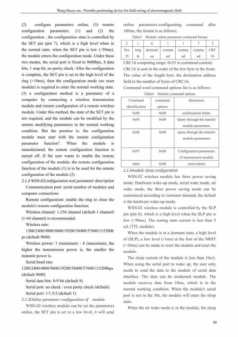
Wang Haoyu etc.: Portable positioning device for field wiring of electromagnetic field
59
(2) configure parameters online, (3) remote configuration parameters. (1) and (2) the configuration , the configuration state is controlled by the SET pin (pin 7), which is a high level when in the normal state. when the SET pin is low (>50ms), the module enters the configuration mode. Under these two modes, the serial port is fixed to 9600bps, 8 data bits, 1 stop bit, no parity check. After the configuration is complete, the SET pin is set to the high level of the ring (>10ms), then the configuration mode (no reset module) is required to enter the normal working state. (3) a configuration method is a parameter of a computer by connecting a wireless transmission module and remote configuration of a remote wireless module. Under this method, the state of the SET pin is not required, and the module can be modified by the remote modifying parameters in the normal working condition. But the premise is: the configuration module must start with the remote configuration parameter function". When the module is manufactured, the remote configuration function is turned off. If the user wants to enable the remote configuration of the module, the remote configuration function of the module (1) is to be used for the remote configuration of the module (2). 2.1.4 WSN-02configuration tool parameter description
Communication port: serial number of modules and computer connections
Remote configuration: enable the ring to close the module's remote configuration function;
Wireless channel: 1-256 channel (default 1 channel) (1-64 channel) is recommended.
Wireless rate: 1200/2400/4800/9600/19200/38400/57600/115200b
ps (default 9600) Wireless power: 1 (minimum) - 8 (maximum), the
higher the transmission power is, the smaller the transmit power is.
Serial baud rate: 1200/2400/4800/9600/19200/38400/57600/115200bps (default 9600)
Serial data bits: 8-9 bit (default 8) Serial port: no check / even parity check (default). Serial port: 1/1.5/2 (default 1)
2.1.5Online parameter configuration of module WSN-02 wireless module can be set the parameters
online, the SET pin is set to a low level, it will send
online parameters-configurating command after 100ms, the format is as follows:
Table3 Module online parameter command format
2 1 6 1 1 7 2
0xx
55
leng
th
destinati
on
comma
nd
comma
nd
comma
nd
CRC
16
CRC16 computing range: 0x55 to command content; CRC16 is sent in the order of the low byte in the front; The value of the length byte: the destination address field to the number of bytes of CRC16; Command word command options list is as follows:
Table4 Module command options
Command
identification
command
options
illustration
0x00 0x00 confirmation frame
0x95 0x00 Query through the transfer
module parameters
0x96 0x00 query through the transfer
module parameters
0x97 0x00 Configuration parameters
of transmission module
other 0x00 reservations
2.1.6module sleep configuration WSN-02 wireless module has three power saving
mode: Hardware wake-up mode, serial wake mode, air wake mode, the three power saving mode can be customized according to customer demand, the default is the hardware wake-up mode. WSN-02 wireless module is controlled by the SLP pin (pin 8), which is a high level when the SLP pin is low (>50ms). The resting state current is less than 5 uA (TTL module).
When the module is in a dormant state, a high level of (SLP), a low level (>1ms) at the foot of the NRST (>10ms) can be made to reset the module and reset the module.
The sleep current of the module is less than 10uA. When using the serial port to wake up, the user only needs to send the data to the module of serial data interface. The data can be awakened module. The module receives data from 10ms, which is in the normal working condition. When the module's serial port is not in the 30s, the module will enter the sleep state.
When the air wake mode is in the module, the sleep

The English Proceedings of the College of Instrumentation & Electrical Engineering, Jilin University, in the Second Half of 2015
60
current is less than 20uA. In the wake of the use of the work mode, the module is in a discontinuous mode of operation, the module is entered into the state of the air, when the air received a certain length of wake-up data, the 10ms module into the normal receiving state. When the module is in the receiving state of the work 30s, there is no data in the air, then enter the sleep state. 2.2 GPS module This project uses the GPS module of the ATK-NEO-6M-V2.3 model. ATK-NEO-6M-V2.3 (V2.3 is the version number) is a high performance GPS positioning module. The module uses the NEO-6M U-BLOX module, the module comes with MAXIM high gain (20.5dB) LNA chip with high performance ceramic antenna, the antenna is composed of antenna, which is equivalent to integrated active antenna (without the need to buy expensive active antenna), of course, in order to have better results, the module also provides IPX interface, for everyone to connect active antenna \, so as to form a double antenna".
Module has EEPROM, all configuration information can be saved in the EEPROM, to meet your various configuration needs, the module also comes with rechargeable backup battery (to support the warm start or hot start, backup battery can be maintained for about half an hour to receive data storage after the main power supply), GPS NEO-6M-V2.3 module features are as follows: 1,use NEO-6M U-BLOX module, compact size, excellent performance. 2, comes with ceramic antenna and 20.5dB MAXIM high gain LNA chip,excellent search ability. 3, can carry out various parameters setbe by the serial port, and can be saved in the EEPROM, convenient to use. 4, comes with IPX interface, can connect all kinds of active antenna, adaptive ability. 5, compatible with the 3.3V/5V level, convenient to connect a variety kinds of single-chip microcomputer system. 6, built-in rechargeable battery back-up, can keep the ephemeris after data power down . 2.2.1 module performance parameters
item illustrate
Receiving
characteristic
s
50 enterclose,GPS L1(1757.42Mhz) C/A
code,SBAS:WAAS//EGNOS/MSAS
positioning
accuracy
2.5Mcep (SBAS: 2.0mCEP)
update rate 5HZ at most
capture time cold start:27s
warm start:27s
hot start:1s
capture
tracking
sensitivity
-164dbm
communicati
on protocol
NMEA(default)/UBX Binary
serial
communicati
on baud rate
4800,9600,19200,38400(default),57600,115200
,230400
working
temperature
-40~85centigrade
module size 25.5mm*31mm
interface
characteristic
TTL,compatible3.3v/5v single chip
microcomputer system
Fig.1 Module performance parameters
Fig.2 Module appearance diagram
Table5 Function description of ATK-NEO-6M module
serial number name Description Illustration
1 PPS clock pulse output pin
2 RXD module serial port
3 TXD module serial port
4 GND ground
5 VCC power supply (3.3V-5.0V)
The PPS pin is connected to the PPS port of the UBLOXNEO-6M module which is connected to the TIMEPULSE port of the module. PPS indicator (that
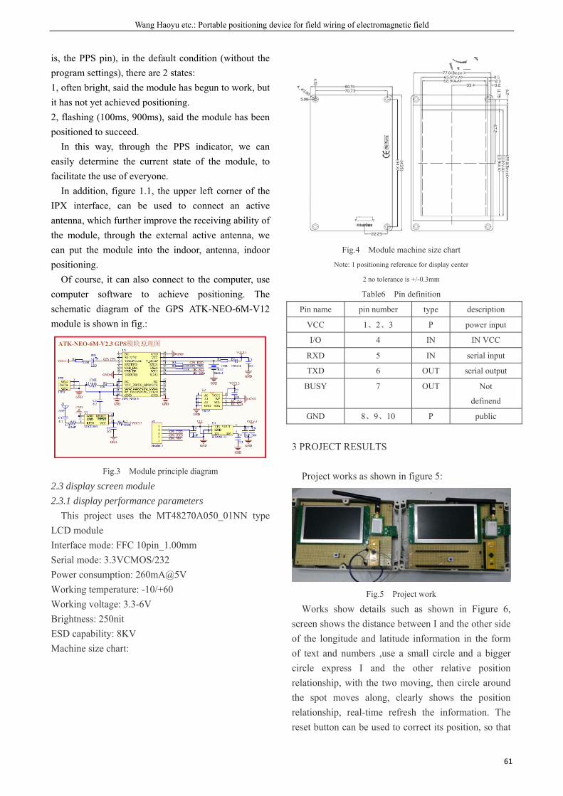
Wang Haoyu etc.: Portable positioning device for field wiring of electromagnetic field
61
is, the PPS pin), in the default condition (without the program settings), there are 2 states: 1, often bright, said the module has begun to work, but it has not yet achieved positioning. 2, flashing (100ms, 900ms), said the module has been positioned to succeed.
In this way, through the PPS indicator, we can easily determine the current state of the module, to facilitate the use of everyone.
In addition, figure 1.1, the upper left corner of the IPX interface, can be used to connect an active antenna, which further improve the receiving ability of the module, through the external active antenna, we can put the module into the indoor, antenna, indoor positioning.
Of course, it can also connect to the computer, use computer software to achieve positioning. The schematic diagram of the GPS ATK-NEO-6M-V12 module is shown in fig.:
Fig.3 Module principle diagram
2.3 display screen module 2.3.1 display performance parameters
This project uses the MT48270A050_01NN type LCD module Interface mode: FFC 10pin_1.00mm Serial mode: 3.3VCMOS/232 Power consumption: 260mA@5V Working temperature: -10/+60 Working voltage: 3.3-6V Brightness: 250nit ESD capability: 8KV Machine size chart:
Fig.4 Module machine size chart
Note: 1 positioning reference for display center
2 no tolerance is +/-0.3mm
Table6 Pin definition
Pin name pin number type description
VCC 1、2、3 P power input
I/O 4 IN IN VCC
RXD 5 IN serial input
TXD 6 OUT serial output
BUSY 7 OUT Not
definend
GND 8、9、10 P public
3 PROJECT RESULTS
Project works as shown in figure 5:
Fig.5 Project work
Works show details such as shown in Figure 6, screen shows the distance between I and the other side of the longitude and latitude information in the form of text and numbers ,use a small circle and a bigger circle express I and the other relative position relationship, with the two moving, then circle around the spot moves along, clearly shows the position relationship, real-time refresh the information. The reset button can be used to correct its position, so that
The English Proceedings of the College of Instrumentation & Electrical Engineering, Jilin University, in the Second Half of 2015
62
its position is reset to the center of the screen, and it will not change the relative position relationship between the two, so that it is not restricted by geographical position.
Fig.6 Work detail display
This project through the microcontroller GPS module, wireless data transmission module and LCD screen display module organically combined.A GPS module receive the latitude and longitude and displayed on the LCD screen with another latitude and longitude ,then calculate the relative distance.and show the relative position in the form of the text and graphics image in real time.the project complete the project's expected target.
Reference
[1] Baixue, Liu Weihai, Xu Leijun, Huang Zhenyue. GPS
positioning information acquisition system based on single
chip microcomputer [J]. micro computer information, 229,
24 (1 - 8):228 – 2008 CN101694740A: ,2010.
[2] Zhang Mohan, Zhangbei, Wang Tianliang. Wireless signal
transmission device and transmission method
CN101694740A: [Z]., 2010
[3] Encyclopaedia Britannica 2007 Ultimate Reference
Suite.Version.2007.01.00.000000000 Encyclopaedia
Britannica, Inc.2007.01 [8] GS1100 Seriers Operational
manual.Verison1.0.Serf Company.2004.11
[4] Li Dawei, Deng Jie, Sun Wenbo, He Qinlong, Ye Xuerong.
Development of wireless signal transmission device based
on magnetic field feedback [J]. electrical and electrical,
2009, (2).
Peng Cong etc.: Design and Implementation of Micro-quality PVDF-based Weighing System
63
Design and Implementation of Micro-quality PVDF-based Weighing System
Peng Cong; Liu Bo; Yan Jiaqi
(jilin university instrument science and engineering institute,changchun,130021)
Abstract-The main design principle using a piezoelectric sensor, with special piezoelectric material polyvinylidene
fluoride (PVDF) good piezoelectric properties, excellent stability, etc., place it on a cantilever, when placed on an
object generates a signal, the first signal through the amplifier circuit, and through the microcontroller analog to
digital conversion processing, to achieve the quality of measurement of small objects.
Key words-PVDF Small mass Cantilever SCM
I. INTRODUCTION
SMALL mass weighing systems mostly in the form of micro-mass sensor reflected. The micro-mass sensor is a tiny mass sensor into a frequency signal. It is being increasingly used in the chemical and biological environment for performing composition analysis of gases and liquids, micro quality measurements, film thickness measurements and pressure testing. And polyvinylidene fluoride (PVDF) as an organic piezoelectric material, the more widely used in underwater acoustic ultrasonic measurement, pressure sensors and other fields. We have now achieved using PVDF piezoelectric sensors to measure power flow and displacement[1] , with high value and broad space for development. The quality measurement also has a unique role.
II.DESIGN OF MICRO-QUALITY WEIGHING SYSTEM
A.Scheme Selection
To complete the design and implementation of small quality weighing system, we have chose two options: One is with the use of quartz crystal resonator resonance characteristics; the other is with the use of PVDF piezoelectric film to achieve. Currently known Quartz Crystal Microbalance (referred QCM) is a typical micro-mass sensor, in different areas and have a wide range of its applications. This sensor is the use of resonance characteristics of quartz crystal resonator, quartz crystal resonator will change the quality of the electrode surface is converted into frequency of quartz crystal oscillator circuit output electrical signal. The disadvantage is that due to the quartz crystal can not be made thin, so its working base frequency is generally in the tens of megahertz or less, its piezoelectricity weak, a low dielectric constant is very
limited. Thus, the measurement of small quality have great difficulties.
The characteristics of PVDF piezoelectric thin film including the high piezoelectric voltage constant, good stability, low density, etc., in the piezoelectric sensor signal aspects, which greatly improved the accuracy of the frequency of the signal on the acquisition and transmission. And then have a major impact on small measurement sensitivity requirements and implementation aspects of difficulty degree of reduction, in addition it has a low impedance, high voltage coefficient, high dielectric strength, high stability and other advantages, rapid development, can significantly improve the measurement accuracy and can simultaneously measure multiple parameters, has great development space and special influence in quality measurement, has a great use of space[4].
Comparing advantages with disadvantages of the above two programs, the final decision is to choose PVDF piezoelectric film to complete the design and implementation of micro-quality weighing systems.
B.The design of piezoelectric cantilever sensors[3]
Sensor uses a piezoelectric cantilever beam structure. The mechanism of piezoelectric cantilever sensors is when the sensor surface adsorption material, the resonant frequency of the sensor is changed, by measuring the change in frequency derived qualitative and quantitative analysis of the results of the test substance. The piezoelectric cantilever sensor as compared with conventional piezoelectric sensor has a small size, simple structure, fast response, high integration, and easy to implement an array of tests and so on. Thus, the design of the sensor cantilever structure decided to adopt in order to effectively enhance the piezoelectric properties. At the same time, the operating mode of the sensor cantilever, the use of dynamic work. Which is also known as resonant work, mainly using cantilever beam after additional small
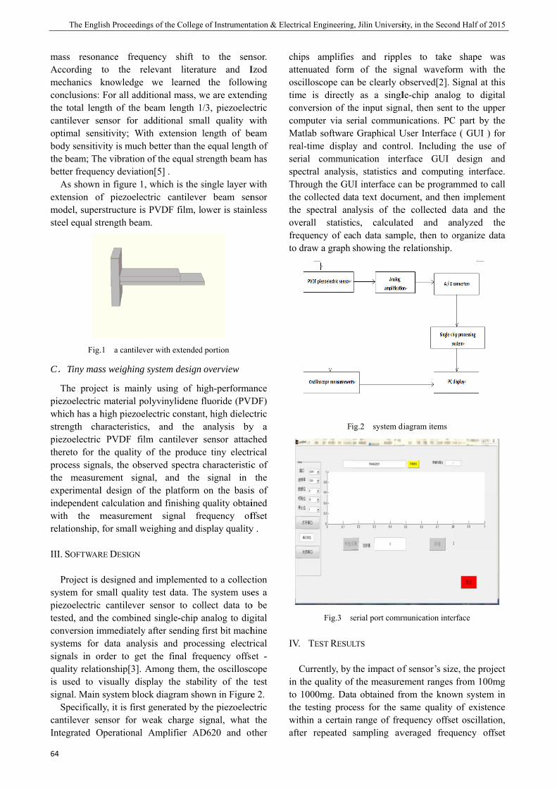
The Engli
64
mass resonAccording mechanics kconclusions: the total lengcantilever seoptimal sensbody sensitivthe beam; Thbetter frequen
As shown extension ofmodel, supersteel equal st
Fig.
C.Tiny mas
The projepiezoelectric which has a hstrength chpiezoelectric thereto for tprocess signathe measureexperimentalindependent with the mrelationship,
III. SOFTWAR
Project is system for smpiezoelectric tested, and thconversion imsystems for signals in orquality relatiis used to vsignal. Main
Specificallcantilever seIntegrated O
ish Proceedings
ance frequeto the releknowledge For all addit
gth of the beensor for adsitivity; Withvity is much bhe vibration oncy deviationin figure 1, wf piezoelectrrstructure is Ptrength beam.
.1 a cantilever
ss weighing sy
ct is mainly material polhigh piezoelearacteristics, PVDF film
the quality oals, the obserement signal design of tcalculation ameasurementfor small we
RE DESIGN
designed andmall quality cantilever she combined mmediately a
data analysrder to get ionship[3]. Avisually dispsystem block
ly, it is first gensor for weOperational A
s of the College
ency shift evant literatwe learned
tional mass, weam length 1dditional smah extension better than thof the equal stn[5] . which is the sric cantilevePVDF film, l.
r with extended
ystem design
y using of hlyvinylidene ectric constan
and the m cantilever
f the producrved spectra
al, and the the platform and finishing t signal frighing and di
d implementetest data. Th
sensor to cosingle-chip
after sending is and procethe final fre
Among them, lay the stabk diagram shogenerated by eak charge sAmplifier AD
e of Instrumenta
to the senture and I
the followwe are extend/3, piezoelecall quality wlength of bee equal lengthtrength beam
single layer wer beam senower is stain
d portion
overview
igh-performafluoride (PVD
nt, high dielecanalysis bysensor attac
ce tiny electrcharacteristicsignal in
on the basisquality obtai
requency ofisplay quality
ed to a collecthe system usellect data toanalog to digfirst bit machessing electrequency offsethe oscilloscility of the own in Figurethe piezoelec
signal, what D620 and ot
ation & Electric
nsor. Izod wing ding ctric with eam h of has
with nsor
nless
ance DF) ctric y a ched rical c of the
s of ined ffset y .
tion es a
o be gital hine rical et -
cope test
e 2. ctric
the ther
chipatteosctimconcomMarealserispeThrthe the ovefreqto d
IV.
Cin tto 1the withafte
cal Engineering
ps amplifiesenuated formilloscope cane is directly
nversion of thmputer via setlab softwarel-time displaial communctral analysirough the GUcollected datspectral ana
erall statistiquency of eadraw a graph
Fi
Fig.3 s
TEST RESUL
Currently, by the quality of1000mg. Dattesting proc
hin a certain er repeated
g, Jilin Universi
s and ripplm of the sign be clearly oy as a singlhe input signerial commune Graphical Uay and contrnication inters, statistics a
UI interface cata text documalysis of thecs, calculatch data sampshowing the r
ig.2 system d
serial port comm
LTS
the impact off the measurea obtained fress for the srange of fre
sampling av
ity, in the Secon
les to take gnal waveforobserved[2]. le-chip analo
nal, then sent nications. PCUser Interfacerol. Includingerface GUI and computian be progra
ment, and thee collected dted and anple, then to orelationship.
diagram items
munication inte
f sensor’s sizement ranges rom the knowsame quality equency offseveraged freq
nd Half of 2015
shape wasrm with theSignal at thisog to digital
to the upperC part by thee ( GUI ) forg the use of
design anding interfacemmed to callen implementdata and thenalyzed theorganize data
rface
ze, the projectfrom 100mg
wn system inof existence
et oscillation,quency offset
5
s e s l r e r f d . l t e e a
t g n e , t
results obtainthe final GUsubjected to great influenpart of the fra certain inst
Fig.4 spectra
V. CONCLUSI
The authoweighing sysand so on. and high sencould be comthat the quaelectrical sigquality expefunctions.
References
[1] Chen Zhe
Zhen Zhen
Based on
Microsyst
[2] Wang Shu
its Applic
Piezoelect
374-376
[3] Li Xue. T
Mass Seno
[4] Zhao Don
Sensor and
[5] Zhang C
Simulation
Peng Con
ned and dispUI interface
vibration annce PVDF firequency offstability.
al analysis, stati
ION
or designed astem, which h
PVDF has nsitivity piezombinated wiality signal gnal, and therimental tes
eng, Zhong Hu
n. Study on Sig
n PVDF Piezo
tems 2012. Vol.
uxin, Li Yizhe.
ation to Measur
tric and acou
The Structure D
or[D]. Dalian u
ngsheng. The
d its Test Resea
Chunjuan ,Luo
n Study of Pie
ng etc.: Design
played at diffon. Since t
nd impact cilm propertieset distortions
istical and comp
a small qualhas high sensgood mechaoelectric plasith the cantil
would be chen finally st system th
uicai, Li Qing,
gnal of Vehical
electric Sensor
. 31 (04): 36-39
The Design of
rement of Vibr
usto-optic.2014
Design of Piezo
university of tec
Design of PV
arch[D]. Jiangsu
o Ying ,Li
zoelectric Micr
and Implement
fferent qualitythe test data
cantilever senes, appear sms, the system
putational interf
ity PVDF-basitivity, precisnical toughnsticity, so thalever to achiconverted torealized a t
hrough softw
Liang Yanju,
Dynamic Weit
r [J]. Sensors
9
PVDF Sensors
ation Paramete
4. Vol. 26 (
oelectric Cantil
chnology.2007
VDF Piezoele
u University.20
Hong. Numer
rocantilever Se
ntation of Micro
y in a is nsor mall has
rface
ased sion
ness, at it ieve
o an tiny
ware
Lin
thing
and
s and
ers[J].
(05):
lever
ectric
005
erical
ensor
o-quality PVDF
Performance[J
Vol. 1 (01):1-4
-based Weighin
J]. Instrument
4
ng System
Technique and
65
d Sensor. 2011
5
.


Wan
Thetan
Abstract-Th
mainly aimed
feedbacks in
resource.This
collect the in
system can pr
tested inform
single oil we
production.
Key words-
I. INTRODUCT
IN the procescollections inthe single oito product oiwhich used toof the singland abroad,spcollection,buoil without the energyprevious ,rpollution,butused also efocus on lownot only waeasy to havbecause of mIn this paper,oil well tansystem,it candisrupt in theresources, irealizing the small-scale osignificance.
II.OVERALL
AS shown
ng Qian etc.: Th
e reseank of i
(jilin univer
his article ma
d at the quest
n time,petrole
s system make
nformation of
revent petrole
mation to the c
ll tank come
The single oil
TION
ss of drilling ncluded pipell well tanks,ail which is so laying pipele oil well tanpecailists not
ut also make texplosion in
y’s utilizatireducing trt now,the singxist many d
w automationaste many hue problems
monitoring unt,we are aimenks’ automatn monitor thee wild,in ordeimproving digital mana
oil drilling a
L DESIGN
n in figure
he research and
arch ainform
Cai Jingrsity instrum
akes design o
tions which t
eum may be
es MCU to be
f petroleum
eum solidifica
computer term
ture,and sig
l well tank;Di
for oil,traditline transportamong them,mall-scale,it
elines.At presnks had gaint only achievethe equipmenn confined son comparraditional gle oil well tadefects,the pn and relying uman resourwhich stopptimely and oid at buildingtic monitorine single oil wer to saving mthe productgement. Thisand saving, i
1,this system
design of the s
and demation
syg; Wang Qi
ment science
of the single o
he single oil
e stolen and
e the main co
in the single
ation and inst
minal by the
gnificantly im
istributed me
tional way oft and stored i,the later is ucan cut fundent,the researed a lot at hoe the oil effic
nt which can hpaces,improvred with heating waanks which wroblems maion manpow
rces.but onlyping productiil stolen. a general sin
ng and conwell tanks whmost of humtion efficiens design aimeit has impor
m include th
single oil well ta
esign on moniystemian; Yang Yand enginee
oil well tank’
well tank exi
d the produc
ontrol and me
oil well tan
tall the anti-t
GSM network
mproves the p
asurement ; I
f oil in a
used ding rchs ome cient heat ving
the ays’
were inly
wer.it y be ions
ngle ntrol hich man ncy,
ed at rtant
hree
sectmonrespsingtemmeathe recestortim
Ⅲ.
Scomthe thedataenc3.1
ank of informat
of the itoring
m Yujing; Li Cering institut
s information
ists now,such
cting of petr
easure unit an
k,includingte
theft alarm de
k.This projec
productivity e
Information c
tions: measunitoring cepansible for gle oil well ta
mperature. Thasure are send
monitoring eived decoraging, PC de to remove o
Figu
SYSTEM SE
System in thmmunication,
measurementemperature
a transmissiocryption.
the PID tempIn the pro
tion monitoring
singleg and
Chang te,changchun
n monitoring
as the single
roleum waste
nd adopts dist
mperature,liq
evice.In the en
t makes the l
efficiency, and
control; GSM
urement partnter. The
collecting anks, includinhe informatid to monitoricenter makeding, extraisplay the inoil .
ure 1.system str
CURITY AND S
he process oin order to g
nt data, using heating modn, the data st
perature contocess of tem
g and control sy
e oil wcontr
n,130021)
and control
e oil well tank
e too much
tributed meas
quid lever an
nd,the system
long-range co
d also saves
network
t,data transmmeasuremen
the informang traffic, liqtions which ing center afte the informacting, sepanformations a
ructure diagram
STABILITY OF
of measuremeguarantee the
g PID algorithdule, and in thtability check
trol algorithmmperature m
ystem
67
well rol
system and
k can’t give
manpower
surement to
nd flow.The
m passes the
ntrol of the
the cost of
mission part,nt part istions in the
quid level andthe system
er encryptionations whicharating andand judge the
m
F THE DESIGN
ent and datae accuracy ofhm to controlhe process ofking and data
m measurement,
7
, s e d
m n, h d e
a f l f a
,
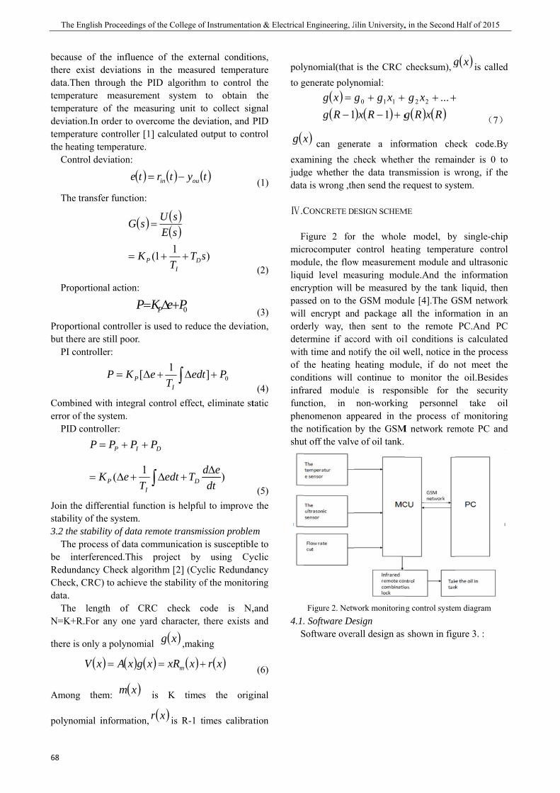
The English
68
because of tthere exist ddata.Then thtemperature temperature deviation.In temperature the heating te Control de
The transf
Proportion
Proportional but there are PI controll
Combined werror of the s PID contro
=
=
K
P
Join the diffestability of th3.2 the stabil The procesbe interfereRedundancy Check, CRC)data. The lengN=K+R.For
there is only
(xV
Among the
polynomial i
h Proceedings o
the influencedeviations in
hrough the Pmeasureme
of the measorder to overcontroller [1]emperature. eviation:
( )te =
fer function:
( )
K
sG
P=
=
nal action:
KP=
controller is still poor.
ler:
Δ= [ eKP P
with integral csystem. oller:
1( ∫+Δ
++=
TeK
PPP
IP
IP
erential functhe system. lity of data ress of data comenced.This Check algor) to achieve t
gth of CRCany one yar
a polynomial
) ( ) (xgxAx =
em: ( )xm
information, r
of the College o
e of the exten the measuPID algorithmnt system suring unit trcome the dev] calculated o
( ) (ytr ouin −=
( )( )11( sTT
sEsU
DI
++
=
0PeKP +Δ
used to redu
∫Δ+1 edT
eI
control effect
∫ +Δ Tedt
P
D
D
tion is helpfu
emote transmimmunication project by ithm [2] (Cycthe stability o
C check crd character,
l ( )xg ,maki
) ( )xxRx m +=
is K time
( )xr is R-1 t
f Instrumentatio
ernal conditioured temperatm to control
to obtain to collect sigviation, and Poutput to con
( )t
)s
ce the deviat
+ 0] Pdt
, eliminate st
)Δdt
ed
ul to improve
ission problemis susceptibl
using Cyclic Redunda
of the monitor
code is N,there exists
ing
( )xr+
s the orig
times calibrat
on & Electrical
ons, ature
the the
gnal PID
ntrol
(1)
(2)
(3) tion,
(4) tatic
(5) the
m le to yclic ancy ring
,and and
(6)
ginal
ation
polyto g
(xg
exajudgdata
Ⅳ.C
Fmicmodliquencpaswillorddetewithof coninfrfunphethe shu
4.1. S
l Engineering, J
ynomial(that generate polyn
( )(Rgxg−=1
)x can geneamining the cge whether ta is wrong ,th
CONCRETE DE
Figure 2 forcrocomputer dule, the flowuid level mecryption will sed on to thel encrypt anerly way, thermine if acch time and nothe heating
nditions will rared modulction, in
enomenon apnotification
ut off the valv
Figure 2. Netw. Software DeSoftware over
Jilin University,
is the CRC nomial:
) ( ) gRxxgg+−++
1110
erate a infocheck wheththe data transhen send the r
ESIGN SCHEM
r the wholecontrol heat
w measuremeeasuring mod
be measurede GSM modud package a
hen sent to cord with oilotify the oil wheating modcontinue to
le is responnon-working
ppeared in thby the GSMe of oil tank.
work monitorinesign rall design as
, in the Second
checksum), g
( ) ( )RxRgxg +++ ...22
ormation cheher the remaismission is wrequest to sys
ME
e model, byating temperaent module adule.And thed by the tankule [4].The Gall the inform
the remote l conditions well, notice idule, if do n monitor thensible for g personnehe process o
M network rem
ng control system
shown in fig
Half of 2015
( )xg is called
+
(7)
eck code.Byinder is 0 towrong, if thestem.
y single-chipature control
and ultrasonice informationk liquid, thenGSM networkmation in an
PC.And PCis calculatedn the processnot meet thee oil.Besidesthe securityl take oilf monitoringmote PC and
m diagram
gure 3. :
d
y o e
p l c n n k n C d s e s y l g d
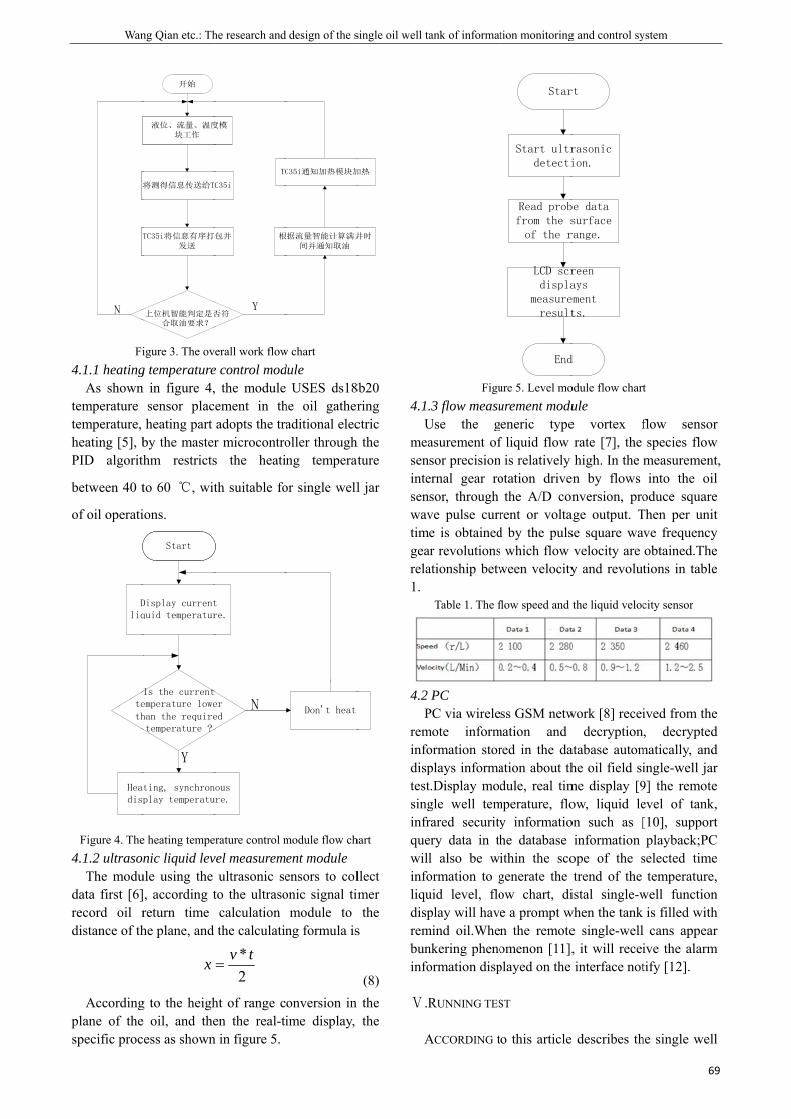
Wan
将
T
N
Fi4.1.1 heating
As showntemperature temperature, heating [5], bPID algorith
between 40 t
of oil operati
Dliq
teth
Headis
Figure 4. The4.1.2 ultrason The modudata first [6]record oil rdistance of th
Accordingplane of thespecific proc
ng Qian etc.: Th
液位、流量、温度块工作
将测得信息传送给T
TC35i将信息有序打发送
上位机智能判定是否合取油要求?
开始
igure 3. The ovg temperaturen in figure 4,
sensor placheating part
by the masterthm restricts
to 60 ℃, wit
ions.
Display currentquid temperatur
Is the currentemperature lowehan the requiretemperature ?
ting, synchronplay temperatu
Y
Start
e heating tempenic liquid lev
ule using the , according treturn time he plane, and
x
g to the heighe oil, and thecess as shown
he research and
度模
C35i
包并
否符
根
TC
Y
verall work flowe control mod, the moduleement in thadopts the trar microcontros the heati
th suitable fo
t re.
er ed
nous ure.
N
erature control mvel measurem
ultrasonic seto the ultrasocalculation the calculatin
2* tv
=
ht of range cen the real-ti
n in figure 5.
design of the s
根据流量智能计算满井
间并通知取油
C35i通知加热模块加
w chart dule
USES ds18he oil gatheraditional elecoller through ng temperat
or single well
Don't heat
module flow chent moduleensors to colonic signal tim
module to ng formula is
onversion in ime display,
single oil well ta
井时
加热
8b20 ring ctric
h the ture
l jar
hart
llect mer the
s
(8) the the
4.1.U
measenintesenwavtimgearela1.
4.2 P
reminfodisptestsinginfrquewillinfoliqudisprembuninfo
Ⅴ.R
A
ank of informat
Figu.3 flow measu
Use the gasurement ofsor precision
ernal gear rosor, through ve pulse curre is obtained
ar revolutionsationship betw
Table 1. The f
PC PC via wirelemote informormation storplays informat.Display modgle well temrared securityery data in thl also be wiormation to guid level, floplay will have
mind oil.Whenkering phenoormation disp
RUNNING TES
ACCORDING t
tion monitoring
Star
Start ultrdetecti
Read probfrom the sof the r
LCD scrdispla
measureresult
End
ure 5. Level mourement modueneric type
f liquid flow is relatively
otation drivethe A/D con
rent or voltad by the puls which flow ween velocity
flow speed and
ss GSM netwmation and red in the daation about thdule, real tim
mperature, floy informatiohe database ithin the scogenerate the ow chart, die a prompt wn the remoteomenon [11],played on the
ST
o this article
g and control sy
rt
rasonic ion.
be data surface range.
reen ays ement ts.
d
odule flow chartule e vortex frate [7], the high. In the m
en by flows nversion, pro
age output. Tse square wavelocity are y and revolut
the liquid veloc
work [8] receidecryption
atabase automhe oil field sime display [9ow, liquid leon such as [
information ope of the strend of the
istal single-wwhen the tank e single-well, it will receiinterface not
e describes th
ystem
69
t
flow sensorspecies flow
measurementinto the oil
oduce squareThen per unitve frequencyobtained.Thetions in table
city sensor
ived from the, decrypted
matically, andingle-well jar9] the remoteevel of tank,[10], supportplayback;PC
selected timetemperature,
well functionis filled withcans appear
ive the alarmtify [12].
he single well
9
r w t, l e t y e e
e d d r e , t
C e , n h r
m
l
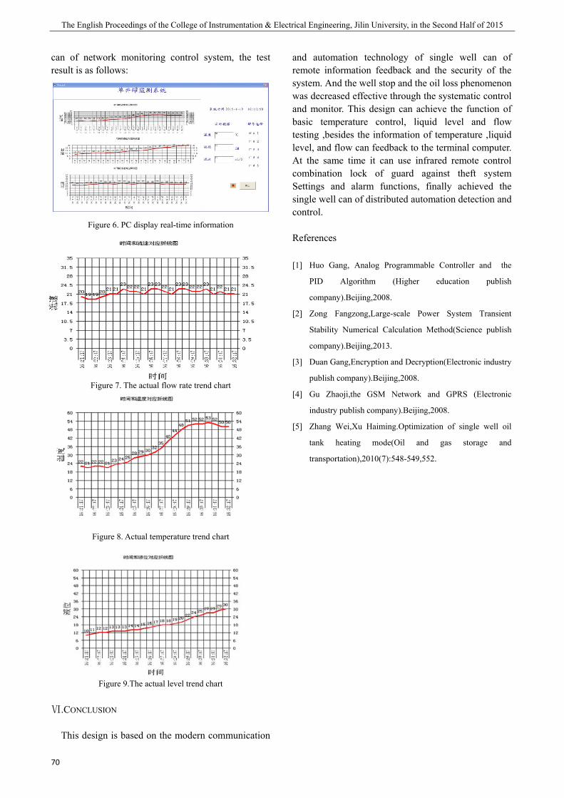
The English Proceedings of the College of Instrumentation & Electrical Engineering, Jilin University, in the Second Half of 2015
70
can of network monitoring control system, the test result is as follows:
Figure 6. PC display real-time information
Figure 7. The actual flow rate trend chart
Figure 8. Actual temperature trend chart
Figure 9.The actual level trend chart
Ⅵ.CONCLUSION
This design is based on the modern communication
and automation technology of single well can of remote information feedback and the security of the system. And the well stop and the oil loss phenomenon was decreased effective through the systematic control and monitor. This design can achieve the function of basic temperature control, liquid level and flow testing ,besides the information of temperature ,liquid level, and flow can feedback to the terminal computer. At the same time it can use infrared remote control combination lock of guard against theft system Settings and alarm functions, finally achieved the single well can of distributed automation detection and control.
References
[1] Huo Gang, Analog Programmable Controller and the
PID Algorithm (Higher education publish
company).Beijing,2008.
[2] Zong Fangzong,Large-scale Power System Transient
Stability Numerical Calculation Method(Science publish
company).Beijing,2013.
[3] Duan Gang,Encryption and Decryption(Electronic industry
publish company).Beijing,2008.
[4] Gu Zhaoji,the GSM Network and GPRS (Electronic
industry publish company).Beijing,2008.
[5] Zhang Wei,Xu Haiming.Optimization of single well oil
tank heating mode(Oil and gas storage and
transportation),2010(7):548-549,552.
Qi Wang etc.: The design of bluetooth entrance control system
71
The design of bluetooth entrance control system
Qi Wang; Chao Yang; Yiguang Bao (College of Instrumentation and Electrical Engineering, Jilin University, Changchun, 130061)
Abstract-This article designs a blue tooth door control system by the use of MCU and motor-driver. The whole
design simulates to open and close the door of garage on the base of MCU STC89C52 and DS1302, LCD and
motor-driver. Garage access control system uses motor-driven program to simulate the realization, when the system
receives a Bluetooth phone to send command to open the door, the motor 10 seconds to perform forward simulation
to achieve open warehouse doors closed when the system receives a Bluetooth phone to send the command C, an
anti-motor 10 seconds to turn off analog implementation warehouse door; system with date and time display
function to record each time the door lock when recording warehouse, collection date and time using the DS1302
clock module, the time and date using LCD1602 LCD display interface display; system uses Bluetooth control end
Android phone APP software manipulation, transmission via Bluetooth data communication and instruction.
Key words-MCU Warehouse control Bluetooth remote control Motor-control
I. INTRODUCTION
ELECTRONIC technology, automatic control technology and the development of computer technology will bring human society into an era of electronic information, electronic control system is widely used in a new technology revolution in the era of digital information. People's pursuit of life intelligence, efficiency and convenience makes the electronic technology has been greatly integrated into the life. Access control system is also known as access control system (CONTROL SYSTEM ACCESS). Is a kind of intelligent management system for the management of personnel. Summary is: management of what people can access those doors, and to provide information on the post, and so on, common access control systems are: password access control systems, non-contact Carmen system, fingerprint iris biometric access control system, and so on, access control system has been widely used in the management control system. Among them, the access control system in human nature, intelligent improvement has become more and more popular, based on the Bluetooth remote control technology of intelligent access control system and in many enterprises and high-end residential to get promotion and application. Access control system as the name suggests is a system of control of the entrance channel, which is based on the development of the traditional door lock. The traditional mechanical lock is a simple mechanical device, no matter how reasonable the structure design, the material is strong, people can always use a variety of means to open it. In the access
to many of the key management of the key is very troublesome, the key is lost or replacement of personnel to the lock and the key to replace. In order to solve these problems, it appeared that the electronic card lock, electronic password lock, the two lock appear in a certain extent, improve the people to go out to ban channel management, channel management into the electronic age, but with the continuous application of electronic lock and their defects gradually exposed, magnetic card lock problem is information is easy to copy, cards and card card between the equipment wear, high failure rate, safety coefficient low. Password lock is the problem is easy to leak, and can not be found, the safety factor is very low. At the same time, this period of products due to the majority of the use of the read card part (password input) and the control part of the installation in the door, it is easy to open the door lock. This period of access control system is still in the early stages of immature, so the access control system is often referred to as electronic lock, the application is not widespread. With the rise of the use of portable devices such as smart phones, tablet PCs, and the rise of the near distance wireless communication technology, access control systems in addition to security, but also need to be able to use access control system to complete a variety of applications. In the future, the security of access control system, integration capability, openness, diversity of applications and mobile intelligent terminal control will be the future development trend. Today, smart phones and other mobile terminal equipment has entered the life, combined with the Bluetooth remote control technology of such mobile
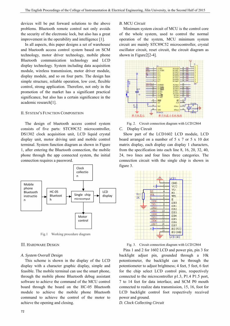
The English Proceedings of the College of Instrumentation & Electrical Engineering, Jilin University, in the Second Half of 2015
72
devices will be put forward solutions to the above problems. Bluetooth remote control not only avoids the security of the electronic lock, but also has a great improvement in the operability and intelligence [1]. In all aspects, this paper designs a set of warehouse and bluetooth access control system based on SCM technology, motor driver technology, mobile phone Bluetooth communication technology and LCD display technology. System including data acquisition module, wireless transmission, motor driver module, display module, and so on four parts. The design has simple structure, reliable operation, low cost, flexible control, strong application. Therefore, not only in the promotion of the market has a significant practical significance, but also has a certain significance in the academic research[1].
II. SYSTEM’S FUNCTION COMPOSITION
The design of bluetooth access control system consists of five parts: STC89C52 microcontroller, DS1302 clock acquisition unit, LCD liquid crystal display unit, motor driving unit and mobile control terminal. System function diagram as shown in Figure 1, after entering the Bluetooth connection, the mobile phone through the app connected system, the initial connection requires a password.
Fig.1 Working procedure diagram
Ⅲ. HARDWARE DESIGN
A. System Overall Design This scheme is shown in the display of the LCD
display with a character graphic display, simple and feasible. The mobile terminal can use the smart phone, through the mobile phone Bluetooth debug assistant software to achieve the command of the MCU control board through the board on the HC-05 Bluetooth module to achieve the mobile phone Bluetooth command to achieve the control of the motor to achieve the opening and closing.
B. MCU Circuit Minimum system circuit of MCU is the control core
of the whole system, used to control the normal operation of the system, MCU minimum system circuit are mainly STC89C52 microcontroller, crystal oscillator circuit, reset circuit, the circuit diagram as shown in Figure2[2-4].
Fig. 2. Circuit connection diagram with LCD12864 C. Display Circuit Show part of the LCD1602 LCD module, LCD board arranged on a number of 5 x 7 or 5 x 10 dot matrix display, each display can display 1 characters, from the specification into each line 8, 16, 20, 32, 40, 24, two lines and four lines three categories. The connection circuit with the single chip is shown in figure 3.
Fig. 3. Circuit connection diagram with LCD12864 Pins 1 and 2 for 1602 LCD and power pin, pin 3 for backlight adjust pin, grounded through a 10k potentiometer, the backlight can be through the potentiometer to adjust brightness; 4 feet, 5 feet, 6 feet for the chip select LCD control pins, respectively connected to the microcontroller p1.3, P1.4 P1.5 port, 7 to 14 feet for data interface, and SCM P0 mouth connected to realize data transmission, 15, 16, foot for LCD backlight control foot respectively received power and ground. D. Clock Collecting Circuit
Mobile phone Bluetooth instruction
Clock collection
Motor control
LCD display
HC‐05 Bluetooth
Single chip microcomput

Qi Wang etc.: The design of bluetooth entrance control system
73
The system clock acquisition circuit sampling DS1302 clock chip as the core device, combined with peripheral circuit to achieve the collection and processing of the clock signal, to change the circuit as shown in figure 4. In which the battery BT1 as the clock chip backup battery, in the case of the system power can guarantee that the clock information is not lost, again on the power system clock time information without the need to re adjust. DS1302 pin 2 and pin 3 pins for the crystal oscillator clock, chip, external 32.768HZ crystal oscillator five feet, 6 feet, 7 feet is and SCM data communication pins and pin output port connected 4.7K to 10K pullup resistor.
Fig. 4 Circuit of time collection
E. Moter Drive circuit The motor drive circuit of the system is realized by ULN2003 integrated circuit, the ULN2003 is low, the peripheral circuit is simple, and is the ideal chip of the small stepping motor driver, which is shown in Figure 5.
Fig. 5. Circuit of Moter Drive
F. Blue tooth Circuit The system uses the HC-05 module as the core of
the system, and the peripheral circuit is designed to complete the system of the Bluetooth communication circuit.
Fig. 6. Circuit Blue tooth Part As shown in Figure 6, the U3 for Bluetooth
communication module HC-05 module, diodes D1 and D2 and a resistor R10, R11 composition level conversion circuit to ensure system can also work under the voltage of 5V and 3.3V, D3 for Bluetooth module working state indicating lamp, and the work of the state are the following three: a power module in the same time the BS-KEY pin is set to high level (or to VCC) at D3 to light a second death a second frequency slow flash module into at. At this time, the baud rate is fixed 38400. Two, the BS-KEY pin is set to a low level (or ground) at the same time, and the D3 takes one second to flash 2 times, which indicates that the module can enter into the D3 state. If the BS-KEY pin level is set high, the module will enter the AT state. Three, the module pair is successful, at this time D3 double flash, flash 2 times, 2 seconds flash once. The system has the D3 indicator light can be very intuitive to judge the current state of the module, easy to use.
IV. SOFTWARE DESIGN
This design through the C language to the bottom of the design, control the microcontroller to coordinate the work of each module, mainly including the clock chip programming, Bluetooth to serial and motor drive design flow chart, such as figure 7[5].
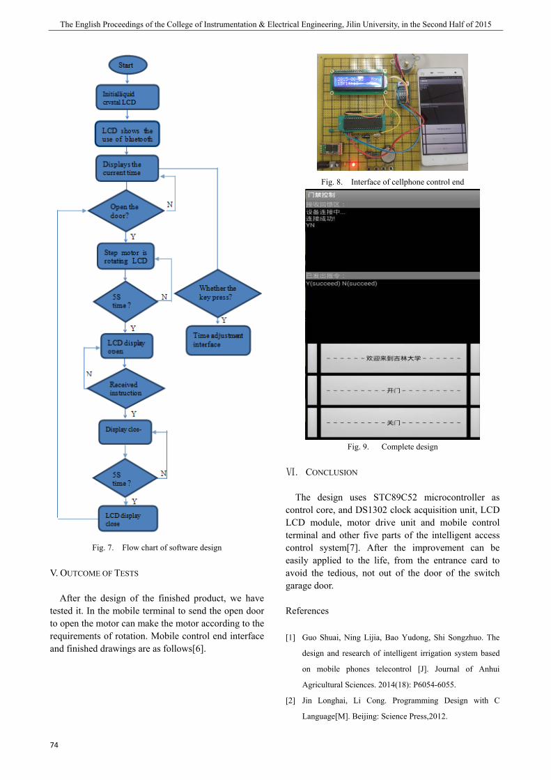
The English Proceedings of the College of Instrumentation & Electrical Engineering, Jilin University, in the Second Half of 2015
74
Fig. 7. Flow chart of software design
V. OUTCOME OF TESTS
After the design of the finished product, we have tested it. In the mobile terminal to send the open door to open the motor can make the motor according to the requirements of rotation. Mobile control end interface and finished drawings are as follows[6].
Fig. 8. Interface of cellphone control end
Fig. 9. Complete design
Ⅵ. CONCLUSION
The design uses STC89C52 microcontroller as control core, and DS1302 clock acquisition unit, LCD LCD module, motor drive unit and mobile control terminal and other five parts of the intelligent access control system[7]. After the improvement can be easily applied to the life, from the entrance card to avoid the tedious, not out of the door of the switch garage door.
References
[1] Guo Shuai, Ning Lijia, Bao Yudong, Shi Songzhuo. The
design and research of intelligent irrigation system based
on mobile phones telecontrol [J]. Journal of Anhui
Agricultural Sciences. 2014(18): P6054-6055.
[2] Jin Longhai, Li Cong. Programming Design with C
Language[M]. Beijing: Science Press,2012.
Qi Wang etc.: The design of bluetooth entrance control system
75
[3] (America) Brey , B.B. The Intel Microprocessors[M].
Beijing: China Machine Press, 2010.6.
[4] He Qiao, Duan Qingming, Qiu Chunling. The Principles
and Application of Microcontrollers[M]. China Railway
Publishing House. 2008.1.
[5] Guo Tianxiang. C Language Courses about 51
Microcontrollers [M]. Beijing: Publishing House of
Electronics Industry, 2009.1.
[6] Li Peng. The design of mobile phones-telecontrolled toy
car based on MCU [J] . Charming China. 2014 (25):119.
[7] Liu Lingyun. Smart home control system [Dissertation]
Master. 2014.


Xiaotong Cui etc.: Ultrasonic Ranging Based on blind navigation Headphones
77
Ultrasonic Ranging Based on blind navigation Headphones
Xiaotong Cui; Zhaofeng Zhang;Xulei Wang
(Instrument Science and Electrical Engineering, Jilin University, Changchun 130012)
Abstract-Studied a control system based on microcontroller as STC89C51 blind navigation headphone three directions
Ultrasonic Ranging System, the hardware and software control system was designed with an adjustable alarm function, With
real-time voice broadcast distance function,easy to carry, and finally to conduct research ranging error improve accuracy,
there are some practical value in the field to guide the blind.
INTRODUCTION
CHINA has the world's largest blind, due to defects in physical, visual impairment who have a lot of inconvenience in life and work, how to make the blind has become a problem on the road or indoor safe walking. In recent years, the continuous development of ultrasonic ranging technology research, ultrasonic dust, fog, the unique advantages of non-contact and attention been found, on the application of ultrasonic distance measurement is more universal. The important issue is how to design major research more practical ultrasonic ranging application in guiding system to achieve an accurate measurement of the guide of the blind system, and be able to accurately prompt, while reducing cost.
1 OVERALL DESIGN
The system consists of four parts: MCU control part, voice alarm part, Ultrasonic Ranging section, LCD display section. SCM is the core component of the system for controlling the coordination of various parts. In operation, microprocessor controlled oscillator source generates signals to drive the ultrasonic sensor, so that they continued firing pulse. Ultrasonic Ranging section, for each ultrasonic transducer, when after the first ultrasonic pulse emission, the counter starts counting, when the first echo pulse is detected, the counter will immediately stop counting, and also calculated from pulse emission to the time difference between the received Δt, and finally the use of the microcontroller to calculate the distance to the obstacle. Voice broadcast in part on
distance plus and minus buttons to set the alarm from the control value of real-time voice broadcast and alarm indication. LCD display section for displaying the current three directions left, front and right side of the distance and display voice broadcast function on or off and alarm from the current through the key set. System structure is as follows:
Fig 1 Diagram of the system’s structure
2 ULTRASONIC DISTANCE MEASUREMENT PRINCIPLE
Ultrasound is a straight line of communication, using the piezoelectric effect to the principle of mutual transformation and ultrasonic energy, the higher the frequency, reflecting the stronger, but weaker diffraction ability. With this feature ultrasonic waves to measure the distance with regular transit time detection. Ultrasonic ranging principle is: When the ultrasonic ranging, under the control of the control circuit, ultrasonic transmitter transmitting a plurality of ultrasonic probe forward, when the ultrasonic obstacle in the air, will be reflected back and received by the ultrasonic probe converted into an electrical
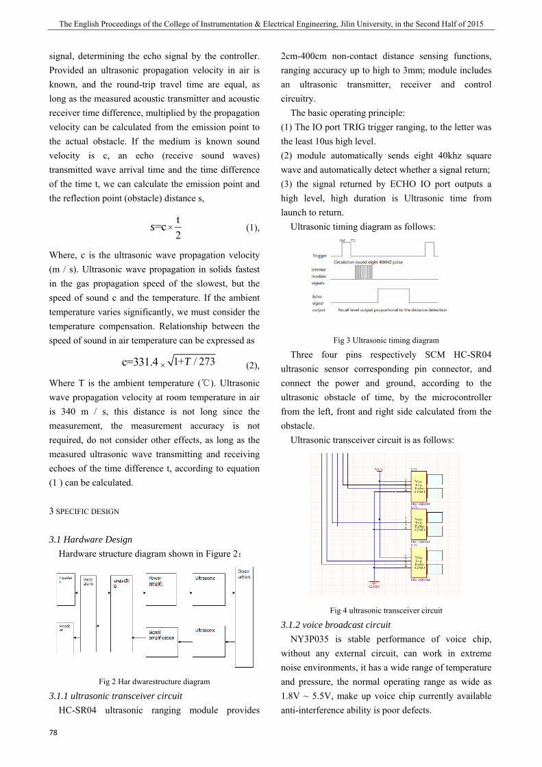
The English Proceedings of the College of Instrumentation & Electrical Engineering, Jilin University, in the Second Half of 2015
78
signal, determining the echo signal by the controller. Provided an ultrasonic propagation velocity in air is known, and the round-trip travel time are equal, as long as the measured acoustic transmitter and acoustic receiver time difference, multiplied by the propagation velocity can be calculated from the emission point to the actual obstacle. If the medium is known sound velocity is c, an echo (receive sound waves) transmitted wave arrival time and the time difference of the time t, we can calculate the emission point and the reflection point (obstacle) distance s,
× (1),
Where, c is the ultrasonic wave propagation velocity (m / s). Ultrasonic wave propagation in solids fastest in the gas propagation speed of the slowest, but the speed of sound c and the temperature. If the ambient temperature varies significantly, we must consider the temperature compensation. Relationship between the speed of sound in air temperature can be expressed as
× (2),
Where T is the ambient temperature (℃). Ultrasonic wave propagation velocity at room temperature in air is 340 m / s, this distance is not long since the measurement, the measurement accuracy is not required, do not consider other effects, as long as the measured ultrasonic wave transmitting and receiving echoes of the time difference t, according to equation (1 ) can be calculated.
3 SPECIFIC DESIGN
3.1 Hardware Design Hardware structure diagram shown in Figure 2:
Fig 2 Har dwarestructure diagram
3.1.1 ultrasonic transceiver circuit HC-SR04 ultrasonic ranging module provides
2cm-400cm non-contact distance sensing functions, ranging accuracy up to high to 3mm; module includes an ultrasonic transmitter, receiver and control circuitry.
The basic operating principle: (1) The IO port TRIG trigger ranging, to the letter was the least 10us high level. (2) module automatically sends eight 40khz square wave and automatically detect whether a signal return; (3) the signal returned by ECHO IO port outputs a high level, high duration is Ultrasonic time from launch to return.
Ultrasonic timing diagram as follows:
Fig 3 Ultrasonic timing diagram
Three four pins respectively SCM HC-SR04 ultrasonic sensor corresponding pin connector, and connect the power and ground, according to the ultrasonic obstacle of time, by the microcontroller from the left, front and right side calculated from the obstacle.
Ultrasonic transceiver circuit is as follows:
Fig 4 ultrasonic transceiver circuit
3.1.2 voice broadcast circuit NY3P035 is stable performance of voice chip,
without any external circuit, can work in extreme noise environments, it has a wide range of temperature and pressure, the normal operating range as wide as 1.8V ~ 5.5V, make up voice chip currently available anti-interference ability is poor defects.
=cs t2
c=331.4 1+ / 273T
Xiaotong Cui etc.: Ultrasonic Ranging Based on blind navigation Headphones
79
NY3P035 voice chip has a set of PWM output, direct push headset, clear sound. Built precise resistance frequency vibrator (maximum error of only + -1%).
Serial sequence is as follows:
Fig 5 Serial Timing Diagram
Voice broadcast circuit part by a voice chip, a tuning capacitors and an earphone device composed by the MCU control section, you can broadcast has been burned good corresponding voice content. Users can hear the broadcast content via headset. 3.1.3 LCD display circuit
Use YM12864R LCD module to display the distance from the obstacle in three directions left, front and right side and all directions. LCD display circuit is as follows:
Fig 6 LCD circuit
3.2 Software Design The system software is modular in design,
communications ultrasonic transducer control, data processing and storage, with the host controller by STC89C51 microcontroller to complete, the main program flow chart shown in Figure 7.
After the control system electrical work, be initialized, set up a series of initial values for the system, including the number of ultrasound transmission interval, the initial value of the timer, distance calculation parameters. After the program controls the transmission ultrasonic wave, and start the timer; in order to avoid receiving sensor receives the ultrasonic wave transmitted directly after the emission
of ultrasonic insert a delay to start the program after receiving echo delay, waiting to receive an echo timeout (in set within a given distance without obstacles) are returned to the front and re-emitting ultrasonic echo if you stop the clock, reading time difference, by the formula (1) calculating the distance, and then transmitted to the host controller via serial communication data, and finally return restart, uninterrupted detection.
Program flow chart is as follows:
Fig 7 Program flow chart
4 TEST RESULTS AND ANALYSIS OF ERRORS
To test the accuracy of measurement of system, the system has carried on the field measurements, the surface smooth cardboard as obstacles to experiment, the left right ranging module of three directions of the mea
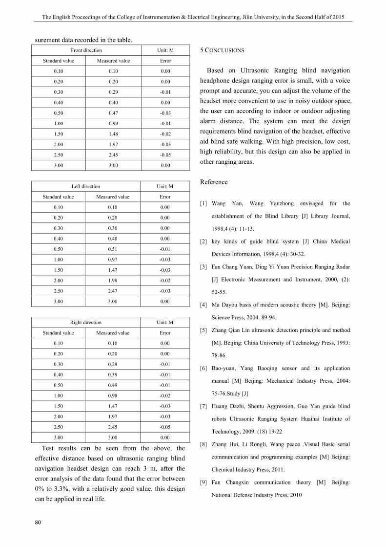
The English Proceedings of the College of Instrumentation & Electrical Engineering, Jilin University, in the Second Half of 2015
80
surement data recorded in the table. Front direction Unit: M
Standard value Measured value Error
0.10 0.10 0.00
0.20 0.20 0.00
0.30 0.29 -0.01
0.40 0.40 0.00
0.50 0.47 -0.03
1.00 0.99 -0.01
1.50 1.48 -0.02
2.00 1.97 -0.03
2.50 2.45 -0.05
3.00 3.00 0.00
Left direction Unit: M
Standard value Measured value Error
0.10 0.10 0.00
0.20 0.20 0.00
0.30 0.30 0.00
0.40 0.40 0.00
0.50 0.51 -0.01
1.00 0.97 -0.03
1.50 1.47 -0.03
2.00 1.98 -0.02
2.50 2.47 -0.03
3.00 3.00 0.00
Right direction Unit: M
Standard value Measured value Error
0.10 0.10 0.00
0.20 0.20 0.00
0.30 0.29 -0.01
0.40 0.39 -0.01
0.50 0.49 -0.01
1.00 0.98 -0.02
1.50 1.47 -0.03
2.00 1.97 -0.03
2.50 2.45 -0.05
3.00 3.00 0.00
Test results can be seen from the above, the effective distance based on ultrasonic ranging blind navigation headset design can reach 3 m, after the error analysis of the data found that the error between 0% to 3.3%, with a relatively good value, this design can be applied in real life.
5 CONCLUSIONS
Based on Ultrasonic Ranging blind navigation headphone design ranging error is small, with a voice prompt and accurate, you can adjust the volume of the headset more convenient to use in noisy outdoor space, the user can according to indoor or outdoor adjusting alarm distance. The system can meet the design requirements blind navigation of the headset, effective aid blind safe walking. With high precision, low cost, high reliability, but this design can also be applied in other ranging areas.
Reference
[1] Wang Yan, Wang Yanzhong envisaged for the
establishment of the Blind Library [J] Library Journal,
1998,4 (4): 11-13.
[2] key kinds of guide blind system [J] China Medical
Devices Information, 1998,4 (4): 30-32.
[3] Fan Chang Yuan, Ding Yi Yuan Precision Ranging Radar
[J] Electronic Measurement and Instrument, 2000, (2):
52-55.
[4] Ma Dayou basis of modern acoustic theory [M]. Beijing:
Science Press, 2004: 89-94.
[5] Zhang Qian Lin ultrasonic detection principle and method
[M]. Beijing: China University of Technology Press, 1993:
78-86.
[6] Bao-yuan, Yang Baoqing sensor and its application
manual [M] Beijing: Mechanical Industry Press, 2004:
75-76.Study [J]
[7] Huang Dazhi, Shentu Aggression, Guo Yan guide blind
robots Ultrasonic Ranging System Huaihai Institute of
Technology, 2009: (18) 19-22
[8] Zhang Hui, Li Rongli, Wang peace .Visual Basic serial
communication and programming examples [M] Beijing:
Chemical Industry Press, 2011.
[9] Fan Changxin communication theory [M] Beijing:
National Defense Industry Press, 2010
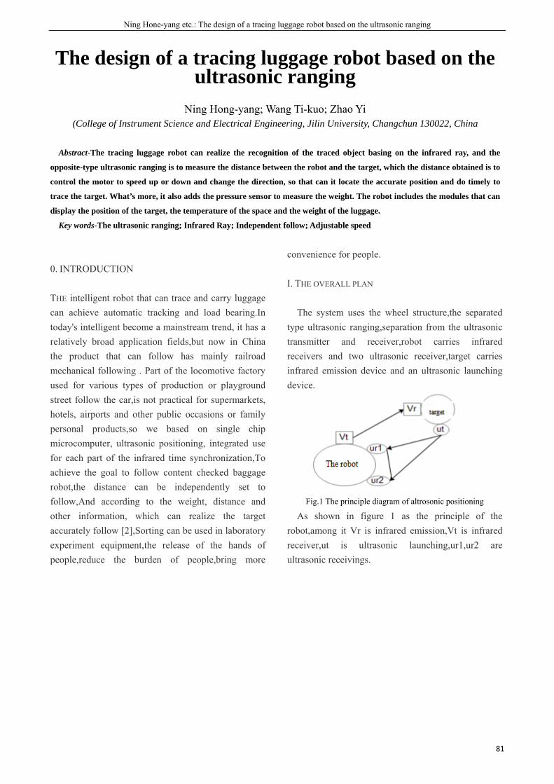
Ning Hone-yang etc.: The design of a tracing luggage robot based on the ultrasonic ranging
81
The design of a tracing luggage robot based on the ultrasonic ranging
Ning Hong-yang; Wang Ti-kuo; Zhao Yi
(College of Instrument Science and Electrical Engineering, Jilin University, Changchun 130022, China
Abstract-The tracing luggage robot can realize the recognition of the traced object basing on the infrared ray, and the
opposite-type ultrasonic ranging is to measure the distance between the robot and the target, which the distance obtained is to
control the motor to speed up or down and change the direction, so that can it locate the accurate position and do timely to
trace the target. What’s more, it also adds the pressure sensor to measure the weight. The robot includes the modules that can
display the position of the target, the temperature of the space and the weight of the luggage.
Key words-The ultrasonic ranging; Infrared Ray; Independent follow; Adjustable speed
0. INTRODUCTION
THE intelligent robot that can trace and carry luggage can achieve automatic tracking and load bearing.In today's intelligent become a mainstream trend, it has a relatively broad application fields,but now in China the product that can follow has mainly railroad mechanical following . Part of the locomotive factory used for various types of production or playground street follow the car,is not practical for supermarkets, hotels, airports and other public occasions or family personal products,so we based on single chip microcomputer, ultrasonic positioning, integrated use for each part of the infrared time synchronization,To achieve the goal to follow content checked baggage robot,the distance can be independently set to follow,And according to the weight, distance and other information, which can realize the target accurately follow [2],Sorting can be used in laboratory experiment equipment,the release of the hands of people,reduce the burden of people,bring more
convenience for people.
I. THE OVERALL PLAN
The system uses the wheel structure,the separated type ultrasonic ranging,separation from the ultrasonic transmitter and receiver,robot carries infrared receivers and two ultrasonic receiver,target carries infrared emission device and an ultrasonic launching device.
Fig.1 The principle diagram of altrosonic positioning
As shown in figure 1 as the principle of the robot,among it Vr is infrared emission,Vt is infrared receiver,ut is ultrasonic launching,ur1,ur2 are ultrasonic receivings.
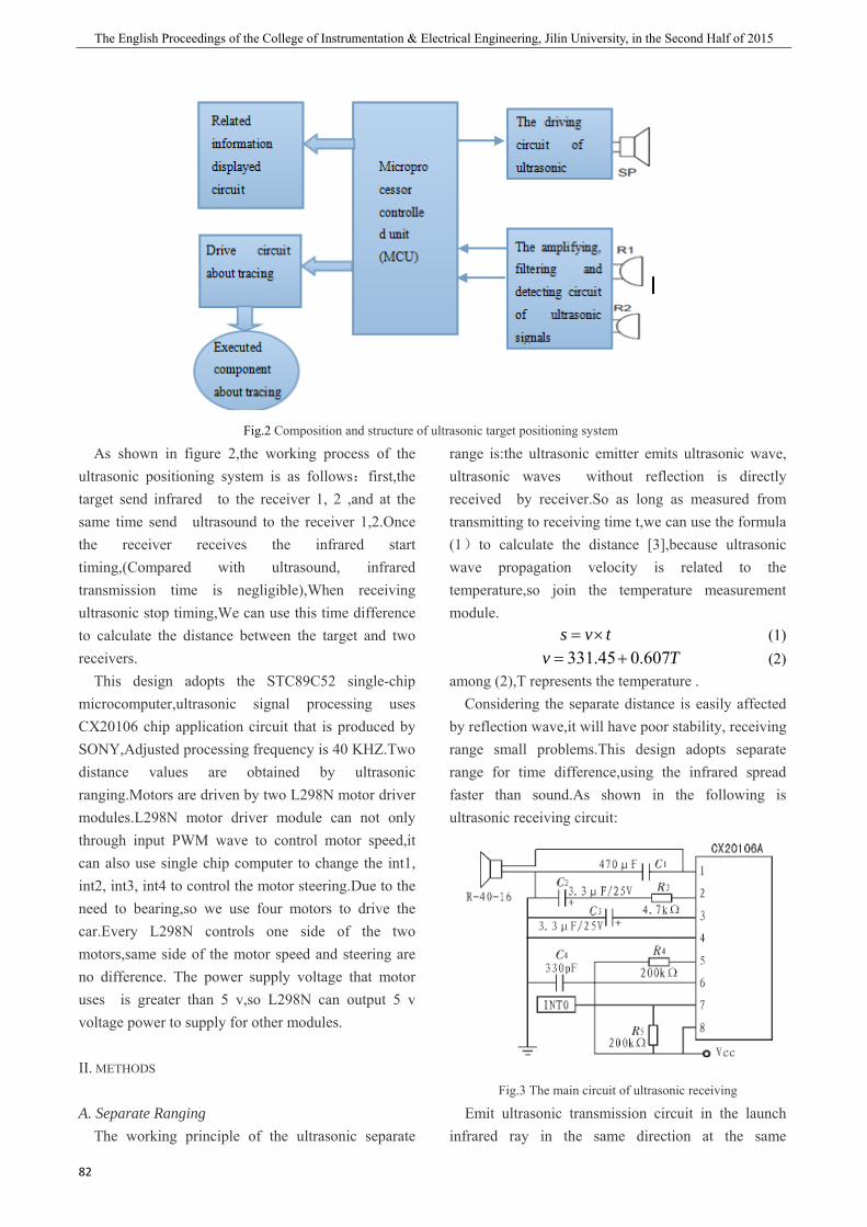
The English Proceedings of the College of Instrumentation & Electrical Engineering, Jilin University, in the Second Half of 2015
82
Fig.2 Composition and structure of ultrasonic target positioning system
As shown in figure 2,the working process of the ultrasonic positioning system is as follows:first,the target send infrared to the receiver 1, 2 ,and at the same time send ultrasound to the receiver 1,2.Once the receiver receives the infrared start timing,(Compared with ultrasound, infrared transmission time is negligible),When receiving ultrasonic stop timing,We can use this time difference to calculate the distance between the target and two receivers. This design adopts the STC89C52 single-chip microcomputer,ultrasonic signal processing uses CX20106 chip application circuit that is produced by SONY,Adjusted processing frequency is 40 KHZ.Two distance values are obtained by ultrasonic ranging.Motors are driven by two L298N motor driver modules.L298N motor driver module can not only through input PWM wave to control motor speed,it can also use single chip computer to change the int1, int2, int3, int4 to control the motor steering.Due to the need to bearing,so we use four motors to drive the car.Every L298N controls one side of the two motors,same side of the motor speed and steering are no difference. The power supply voltage that motor uses is greater than 5 v,so L298N can output 5 v voltage power to supply for other modules.
II. METHODS
A. Separate Ranging The working principle of the ultrasonic separate
range is:the ultrasonic emitter emits ultrasonic wave, ultrasonic waves without reflection is directly received by receiver.So as long as measured from transmitting to receiving time t,we can use the formula (1)to calculate the distance [3],because ultrasonic wave propagation velocity is related to the temperature,so join the temperature measurement module.
tvs ×= (1) Tv 607.045.331 += (2)
among (2),T represents the temperature . Considering the separate distance is easily affected
by reflection wave,it will have poor stability, receiving range small problems.This design adopts separate range for time difference,using the infrared spread faster than sound.As shown in the following is ultrasonic receiving circuit:
Fig.3 The main circuit of ultrasonic receiving
Emit ultrasonic transmission circuit in the launch infrared ray in the same direction at the same
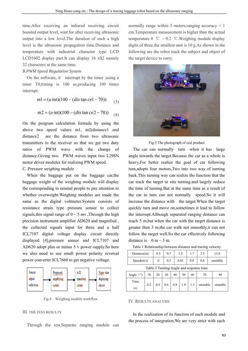
Ning Hone-yang etc.: The design of a tracing luggage robot based on the ultrasonic ranging
83
time,After receiving an infrared receiving circuit boosted output level, wait for after receiving ultrasonic output into a low level.The duration of such a high level is the ultrasonic propagation time.Distance and temperature with industrial character type LCD LCD1602 display part.It can display 16 x02 namely 32 characters at the same time. B.PWM Speed Regulation System
On the software, it interrupt by the timer ,using a timer T0,timing is 100 us,producing 100 times interrupt.
))701tan(100int)((1 −−= cedisum (3)
))702tan(100int)((2 −−= cedisum (4)
On the program calculation formula by using the above two speed values m1, m2(distance1 and distance2 are the distance from two ultrasonic transmitters to the receiver so that we get two duty ratios of PWM wave with the change of distance.Giving two PWM waves input two L298N motor driver modules for realizing PWM speed. C. Pressure weighing module When the baggage put on the baggage car,the baggage weight of the weighing module will display the corresponding to remind people to pay attention to whether overweight.Weighing modules are made the same as the digital voltmeter.System consists of resistance strain type pressure sensor to collect signals,this signal range of 0 ~ 5 mv ,Through the high precision instrument amplifier AD620 and magnified , the collected signals input for three and a half ICL7107 digital voltage display circuit directly displayed [4],pressure sensor and ICL7107 and AD620 adopt plus or minus 5 v power supply.So here we also need to use small power polarity reversal power converter ICL7660 to get negative voltage.
Fig.4 Weighing module workflow
III. THE TEST RESULTS
Through the test,Separate ranging module can
normally range within 5 meters,ranging accuracy < 1 cm.Temperature measurement is higher than the actual temperature 0 ℃ ~ 0.2 ℃.Weighing module display digits of three,the smallest unit is 10 g.As shown in the following are the robot track the subject and object of the target device to carry.
Fig.5 The photograph of real product
The car can normally turn when it has large angle towards the target.Because the car as a whole is heavy.For better realize the goal of car following turn,adopts four motors,Two into two way of turning back.This turning way can realize the function that the car track the target in situ turning.and largely reduce the time of turning.But at the same time as a result of the car in turn can not normally speed.So it will increase the distance with the target.When the target quickly turn and move on,sometimes it lead to follow the interrupt.Although separated ranging distance can reach 5 m,but when the car with the target distance is greater than 3 m,the car walk not smoothly,it can not follow the target well.So the car effectively following distance is 0 m ~ 3 m.
Table 1 Relationship between distance and tracing velocity
Distance(m) 0.5 0.7 1.2 1.7 2.5 ≥3.0
Speed(m/s) 0 0.5 0.65 0.8 0.8 unstable
Table 2 Turning Angle and response time
Angle(°) 10 20 30 40 50 60 70 80
Time
(s) 0.2 0.4 0.6 0.8 1.0 1.3 unstable unstable
IV. RESULTS ANALYSIS
In the realization of its function of each module and the process of integration,We are very strict with each

The English Proceedings of the College of Instrumentation & Electrical Engineering, Jilin University, in the Second Half of 2015
84
module voltage,and through the voltage regulator module to ensure reliable data is provided for all components of the standard voltage.So for each error causes,Don't take into consideration the fact that the input voltage.No security around the temperature sensor of other components,The error of temperature measurement is likely to be the cause of the sensor itself.The error of weighing module is mainly caused by the limitation of the ICL7107 display circuit,In the process of zero,Because of the limitations on display,There is no guarantee that exactly zero,And in the process of weighing,100 g - 109.9 g shows the result is 100 g.So the error of weighing module 0 g ~ 10 g. Separate ultrasonic ranging module to normal range within the 5 m,And within the scope of the 3 m ~ 5 m not normal to follow,the reason is that in the distance in 3 m ~ 5 m range,ultrasonic receiving greatly influenced by the angle,slight angle change could lead that a receiver can not receive ultrasonic .But 3 m distance has meet the design requirements.The biggest problem is the follow performance which is the most important.For better implementation following the performance,on the hardware and software need to be improved.To solve the case now,we should adopt rated voltage for the larger motor,the diameter of the wheel should be increased immediately.So that we can in the side of the motor forward side of the brake,even on both sides of the motor is turning but the realization of turning speed of varying circumstances.This can be avoided in the process of driving the car with the target was interrupted by the distance is too large to follow.But at the same time,the output of the power supply voltage and capacity must also increase.On the program,for a better implementation of follow,on the basis of the hardware upgrade,you can use a variety of ways to turn to make the target in every position the car the car is good to follow.Add turn back and back of the control program,we can make the car following will be improved. Through actual use,this design can also be more perfect in function.Such as add the function of remote control,we can make the person carries through body positioning device to start-stop trolleys,and in the start state,If the baggage do not receive ultrasound,it will spin around,until it find targets.In addition,this design also lacks obstacle avoidance function,if used
in many cases,we still need to add other recognition.
V. CONCLUSION
This paper introduces the automatic follow robot system based on ultrasonic positioning,using ultrasonic sensors and infrared device to realize real-time following the car.By experimental verification,robot’s reaction speed is sensitive.Within the detection range on a single target can effectively track the object,(it can keep synchronization within 3 m distance with master to follow),and by setting the distance between the two receiving sensor can reduce the robot to track the dead zone.The system uses lithium batteries,DC motors control speed,simple structure,easy to implement,the cost is not high.Hope that can be applied to public or industrial handling purposes,bring more convenience for people.
References
[1] Cai lei, zhou Ting-ting, Guo yun-peng,Chen Su-fang, Wu
Han-bang. Intelligent follwing carrige based on ultrasonic
positioning[J]. Electronic measurement technique, 2013,
36(11):76-79
[2] Li Xiao-run, Xie Dong.Design of Intelligent Object
Tracking Baggage Vehicle Based on Binocular Vision[D].
Zhejiang University.2013,20(1):98-101
[3] Chen Ting,Zhang Yu-fang,Zheng Ming-cheng,Wang
Fu-dong. The target tracking robot based on the
ultrasonic detection, 2009,1:36-37
[4] Ju Min-hua. The Application of Digital Volmeter Circuit
formed by ICL7107[J]. Neijiang technology, 2009,
20(6):74