college on medical physics. digital imaging science and
TRANSCRIPT

2166-Handout
College on Medical Physics. Digital Imaging Science and Technology to Enhance Healthcare in the Developing Countries
Slavik Tabakov
13 September - 1 October, 2010
King’s College London United Kingdom
Basis of Computed Radiography & PACS

Basis of Computed Radiography & PACS
Slavik [email protected]
Digital Film-screen
,PDJH�FRPSDULVRQ�DQG�LPDJH�WUDQVIHU�WKURXJK�YDULRXV�V\VWHPV

Source: A. Pascoal
CR system using laser stimulated storage phosphor screens
Very similar radiographic usage:
X-tube>patient>cassette>Reader> >re-use

Photo-stimulated luminescence mechanism
The storage phosphor, usually made fromBaFX:Eu2+ (X=Cl, Br, I)is contained within a cassette, similar in appearance to those used in film-screen radiography.
Eu2+ >> x-ray >> Eu3+ + free e
free e >> into bromine energy traps
Eu3+ + free e >> IR laser >> Eu2+ + PSL (390 nm)
He-Ne laser stimulus infra-red (632 nm)
Eu characteristic radiation (PSL) – 390 nm (ultra-violet)
Fast scanning (PSL~0.8 ms)
Ultra violet
Infra red
He-Ne laser Commercial plates matrix:
1760x2140 (standard resolution): 2000X2510 (high resolution)
Resolution ~ 3 - 5 lp/mm (12 bits)

Storage-Phosphor (CR) against Film-Screen
-Much higher dynamics of CR (1:10000)
-Virtually no bad CR exposures (repetition)
-Very good contrast of CR
- Image processing in CR plus edge enhance
- Digital storage and retrieval of CR images
- Patient dose reduction
- Radiographic techniques preserved
- Film still with better resolution (mammo)
- Often CR images printed with laser imager
The wide dynamic range of CR systems is an advantage, but could easily lead to overexposure of patient
Optimization of CR procedures !
Source: A. Pascoal

where: Xabs = fraction of incident x-ray photons absorbed in the phosphor layerCV(E) = coefficient of variation of the x-ray energy absorbed in the phosphor layerCV(el) = coefficient of variation in the number of trapped electrons for a given absorbed energyCV(S) = coefficient of variation of the light signal emerging from the phosphor for a given number of trapped electrons<g> = the average number of photoelectrons detected per absorbed x-ray
DQEX
[1 + CV(E)][1 + CV(el)][1 + CV(S)] + < g >PSPabs
-1
The simplest definition of detective quantum efficiency can be stated in the formula. It shows that the DQE is the ratio of the output SNR squared to the input SNR squared.
DIGITAL Radiography (DDR) –Flat Panel Detector (FPD)
Indirect ConversionDetector: Scintillator + a-Si diode (ex: CsI)Readout: Thin-Film-Transistor
Direct ConversionDetector: Photoconductor (ex: a-Se)Readout: Thin-Film-Transistor
pixel (0,10-0,20 mm)
hair

Digital Radiography with
Flat Panel Detectors
INDIRECT(a-Si diode – only for the electronics)
The X-ray sensitive converter is normally the needle-shaped CsI phosphor (used also in Image Intensifiers).
The light is detected by a matrix with array of sensors (a-Silicone diodes), each with own switching element – the readout is line-by-line (through address drivers), followed by amplification and A/D converter.
,QGLUHFW�GHWHFWRU�SULQFLSOH��VHQVLWLYLW\�DQG�VSDWLDO�UHVROXWLRQ�RI�SKRVSKRU

,QGLUHFW�GHWHFWRU�ದ �&V, 3KRVSKRU���6L 'HWHFWRU�
� 6SDWLDO�UHVROXWLRQ�GHSHQGV�RQ�SL[HO�VL]H�DQG�SKRVSKRU�EOXU
�'XH�WR�WKH�EOXU��VOLJKW��WKH�LQIOXHQFH�RI�KLJK�IUHT��VLJQDOV�LV�UHGXFHG��KHQFH�OHVV�QRLVH��DQG�EHWWHU�FRQWUDVW
� EHVW�'4(�IRU�DOO�'LJLWDO�GHWHFWRUV
Detector size 43x43 cm, matrix 3000x3000 (pixel size 0.14 mm) > Resolution >3 Lp/mm
DQE ~ 60% (twice the conventional film/screen)
Allows integration with Bucky table (anti-scatter)
Very high workflow (patient flow)
Still quite heavy detector
Due to the rapid-sequence imaging, it is expected that in future the flat detector will replace the Image Intensifier TV systems in real-time examinations (fluoroscopy)

Digital Radiography with Selenium Philips Thoravision
Uses amorphous Selenium (similar to xeroradiography)
Direct conversion of X-ray quanta into electrical charge –avoids noise from conversion
Flat Panel Detectors – DIRECT (a-Se)
'LUHFWO\�OLQNHG�WR�3$&6
D�6H�SULQFLSOH
&DSDFLWRUV�DQG�JDWHV
)LOO�IDFWRU

Drum with 50 cm diameter
0.5 mm Selenium (43x49cm)
Read-our array of 36 probes
2000x2000 pixels (each 0.2mm, 14 bits)
Excellent contrast (wide dynamic)
No transport of cassettes (fast radiography)
Directly linked to PACS
No intermediate light – the signal is transferred through electrical charge.
very good sp. Resolution (less spread)-Theoretically up to 20lp/mm for a-Se
but also less absorption in a-Se and hence reduced DQE.
The decrease fo signal leads to reduced Signal/Noise Ratio (and less contrast)
Direct Radiography – FPDoverview
Direct Conversion(photoconductor + TFT)
TFT*
X-rays
n
p
i
CsI:Tl light
+ + + + + + +- - - -- - -
charge
*Thin-Film Transistor
• Indirect Conversion(scintilator + a-Si/TFT)
scintillator
Photodíode (a-Si:H)
photoconductor
TFT
E
X-rays
TFT
E+- charge
a-Se
*Thin-Film Transistor

Direct Radiography– CCD
Detector:
Scintillator
Read-out:
Charge-Coupled DeviceCCD
5cm x 5cmpixel size
(50-100 m)
1024x1024
X-rays
Optic fibre (light guide)
scintillator(CsI:Tl) light
CCD
Each pixels in a Digital camera includes a photo sensor (photosite) which collects and stores photons, and a CCD which transfers the signal to a readout register. The relative quantity of photons in each photosite cavity are sorted into various intensity levels.
Micro-lens between photositescollects max number of photons
The final image is processed by special imager to finalise the resolution, contrast and colour.
The imaging chain includes:
-Photo optics (+colour filters)
-Photo detectors (photosites)
-Charge-coupled device
-Readout register + Imager
-Software (algorithm)
CCD basic principle
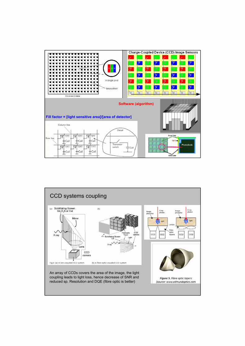
Fill factor = [light sensitive area]/[area of detector]
Software (algorithm)
&&'�V\VWHPV�FRXSOLQJ
$Q�DUUD\�RI�&&'V FRYHUV�WKH�DUHD�RI�WKH�LPDJH��WKH�OLJKW�FRXSOLQJ�OHDGV�WR�OLJKW�ORVV��KHQFH�GHFUHDVH�RI�615�DQG�UHGXFHG�VS��5HVROXWLRQ�DQG�'4(��ILEUH�RSWLF�LV�EHWWHU��
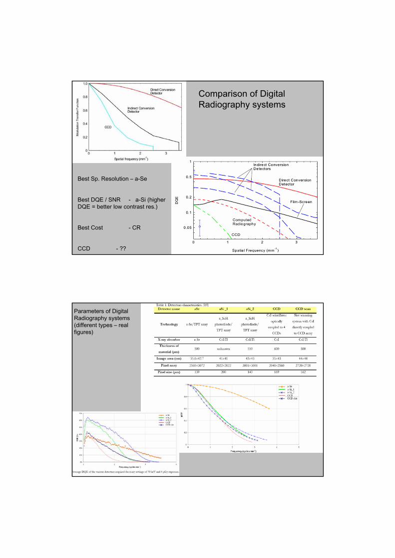
&RPSDULVRQ�RI�'LJLWDO�5DGLRJUDSK\�V\VWHPV
%HVW�6S��5HVROXWLRQ�ದ D�6H
%HVW�'4(���615������ D�6L �KLJKHU�'4(� �EHWWHU�ORZ�FRQWUDVW�UHV��
%HVW�&RVW����������������� &5
&&'����������������� ""
3DUDPHWHUV�RI�'LJLWDO�5DGLRJUDSK\�V\VWHPV��GLIIHUHQW�W\SHV�ದ UHDO�ILJXUHV�
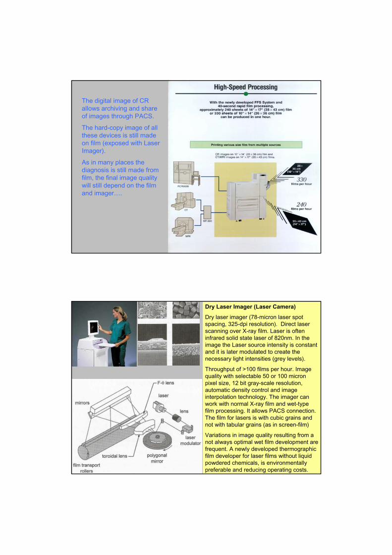
The digital image of CR allows archiving and share of images through PACS.
The hard-copy image of all these devices is still made on film (exposed with Laser Imager).
As in many places the diagnosis is still made from film, the final image quality will still depend on the film and imager….
Dry Laser Imager (Laser Camera)
Dry laser imager (78-micron laser spot spacing, 325-dpi resolution). Direct laser scanning over X-ray film. Laser is often infrared solid state laser of 820nm. In the image the Laser source intensity is constant and it is later modulated to create the necessary light intensities (grey levels).
Throughput of >100 films per hour. Image quality with selectable 50 or 100 micron pixel size, 12 bit gray-scale resolution, automatic density control and image interpolation technology. The imager can work with normal X-ray film and wet-type film processing. It allows PACS connection. The film for lasers is with cubic grains and not with tabular grains (as in screen-film)
Variations in image quality resulting from a not always optimal wet film development are frequent. A newly developed thermographicfilm developer for laser films without liquid powdered chemicals, is environmentally preferable and reducing operating costs.

X-ray film with dry processing methods:
1. Adherographic – laser sensitive adhesive layer + imaging layer (carbon particles), both sandwiched between 2 polyester sheets. When the laser beam scans the dry-film it causes the adhesive layer to take carbon and stick it to the polyester sheet. As a result there are 2 sheets with positive and negative image. The first is coated and used as film, the other is disposed. The adhesion process is binary and the grey tone (nuance) is produced by dithering. Normally a cell of 16x16 pels makes a pixel with 256 grey levels. This requires very thin laser and small pells (5
m) – 16x5 = 80 m pixel = 6.25 lp/mm
2. Thermal - a combination of silver behanate and silver halide over polyester. The scanning laser beam triggers “thermal developing process” producing a “true” gray scale. However there is no fixer – I.e. the undeveloped silver halide crystals remain on the film, what makes it thermally unstable.
* These imagers could have less grey levels as they are used with img. methods using “window”
SONY D71XR Laser Imager (Direct Thermal Printing)
Resolution: 300 dpi (with blue thermal film)
Gradation: 256 grey levels (memory: 16 MB)
Effective Print Pixels: 2743 x 2320 dots
Print Area: (232.2 x 196.4 mm); Interface: SCSI
Printing Time: Approx. 45 seconds
Simple PACS architecture
Image move (ATN): min 150 Mbits/sec;
Fibre opt. 600 Mbits/sec
Storage capacity: average 1800 Gbytes for 1 million images (based on 600 beds hospital)

DICOM standard facilitates interoperability of devices claiming conformance,…but does not guarantee, by itself, interoperability
Promote communication of digital images;
Includes protocols, syntax and semantics;
Provides a common format
DICOM: Digital Imaging and Communication in Medicine
Radiology Dept. RIS
Gamma Camera
MRI
CT
Viewing station 2
PACS
Viewing station 1
CR
Ultrasound
HISIntegrated Hospital Information System
Other Patient Data
Other departments
Inter – Imaging communication through DICOMformat

X-ray film Laser digitizer (with signal proportional to OD)
The laser beam is focussed and moved across the film through galvano-motor (its torque is proportional to the current). The scanning beam passes through reflective tube (with narrow slit) and after many reflections reaches the PMT detector. The log amplifier corrects for OD = log10(1/T)
Reminder for : Light Transmittance (T) and Optical Density (OD)
T = I/Io [max T=1] ; OD = log10(1/T) [min OD = 0]
OD = 1 >>> T=0.1 medium grey
OD = 2 >>> T=0.01 dark
OD = 3 >>> T= 0.001 very dark [max.OD=4]
Turnaround time
Before and after PACS KWWS���ZZZ�FRQQHFWLQJIRUKHDOWK�QKV�XN�
3$&6�GLVDGYDQWDJHV�� &RVW�� 7UDLQLQJ� 5HOLDQFH�RQ�VHUYHUV�DQG�QHWZRUNLQJ� 3$&6�IDLOXUH�XSGDWH�FRQWLQJHQF\�SODQV

)RU�VFDQQHUV�WKH�ILQDO�UHVROXWLRQ�ZLOO�GHSHQG�QRW�RQO\�IURP�WKH�PDWUL[�VL]H��EXW�DOVR�IURP�WKH�GHQVLW\�RI�SURMHFWLRQV��,I�D�&7�VFDQQHU�KDV�����PP�VFDQQLQJ�GLDPHWHU�DQG�WKH�PDWUL[�LV�����[�����SL[HOV��WKH�SL[HO�VL]H�ZLOO�EH�����PP������������ ���OS�PP��,I�WKH�VFDQQHU�KDV�FROOHFWHG�VXIILFLHQW�QXPEHU�RI�SURMHFWLRQV��WKHQ�SDUW�RI�WKLV�UDZ�GDWD�FDQ�EH�XVHG�IRU�VXEVHTXHQW�UHFRQVWUXFWLRQ�RI�DQRWKHU�VPDOOHU�LPDJH��)RU�H[DPSOH�LI�D�52,�ZLWK�GLDPHWHU�����PP�LV�UHFRQVWUXFWHG��WKH�SL[HO�VL]H�RI�WKH�ILQDO�LPDJH�ZLOO�EH�������PP�������������ZKDW�ZLOO�SUHVHQW��VSDWLDO�UHVROXWLRQ�RI���OS�PP�
0DWUL[�GHSWK��KRZ�PDQ\�ELWV�DUH�LQFOXGHG�LQ�RQH�SL[HO��UHIHUV�WR WKH�FRQWUDVW�UHVROXWLRQ��&RQWHPSRUDU\�PHGLFDO�LPDJLQJ�PDWULFHV�KDYH����ELWV�RI�GHSWK��RI�ZKLFK����ELWV�DUH�XVHG�IRU�GLVSOD\LQJ�WKH�OHYHO�RI�JUH\�RI�WKH�SL[HO��DQG�WKH�RWKHU���ELWV�DUH�XVHG�IRU�VXSSRUWLQJ�LQIRUPDWLRQ��WH[W�RU�JUDSKV���7KH����ELWV�SUHVHQW������� ������OHYHOV�RI�JUH\��RU�FRORXUV���ZKDW�LV�PRUH�WKHQ�HQRXJK�IRU�WKH�KXPDQ�YLVXDO�V\VWHP�������OHYHOV�RI�JUH\�LV�DOVR�FRPSOHWHO\�VXIILFLHQW�IRU�YDULRXV�GHQVLWRPHWULF PHDVXUHPHQWV�
)LQDOO\�D�PDWUL[�VL]H�FDQ�EH�GLVSOD\HG�����[����[������PHJD�SL[HO�PDWUL[���ZKDW�ZLOO�SUHVHQW�DSSUR[�����0HJD�ELWV��3UHVHQWHG�LQ�%\WHV����E\WH� ���ELWV���WKH�LPDJH�ILOH�VL]H�ZLOO�EH���0%�
,PDJH�TXDOLW\�DQG�PDWUL[�VL]H
0DWUL[�VL]H�RI�����[�����SL[HOV�FDQ�SUHVHQW�UHVROXWLRQ�IRU�ILHOG VL]H����[����PP�RI�WKH�RUGHU�RI�����PP�SL[HO�VL]H������������ �����OS�PP��6PDOOHU�LPDJH�ILHOG�����[����PP���ZLOO�KDYH�WKH�VDPH�UHVROXWLRQ��GXH�WR�WKH�JHRPHWU\�RI�WKH�LPDJH��
SNR - Signal-to-noise ratio. The ratio of noise to picture signal information (ICRP 93 Glossary).
In the context of the signal detection theory, the SNR is proportional to a ratio of the magnitude of the difference between the mean values of some quantity under two conditions that are to be distinguished, to a measure of the magnitude of statistical variation in that difference.
SNR= [mean(background)-mean(ROI)] / {1/2[std2(ROI)+std2(background)]}1/2
ROI = Region of interest
Physical aspects of image quality and Practical examples
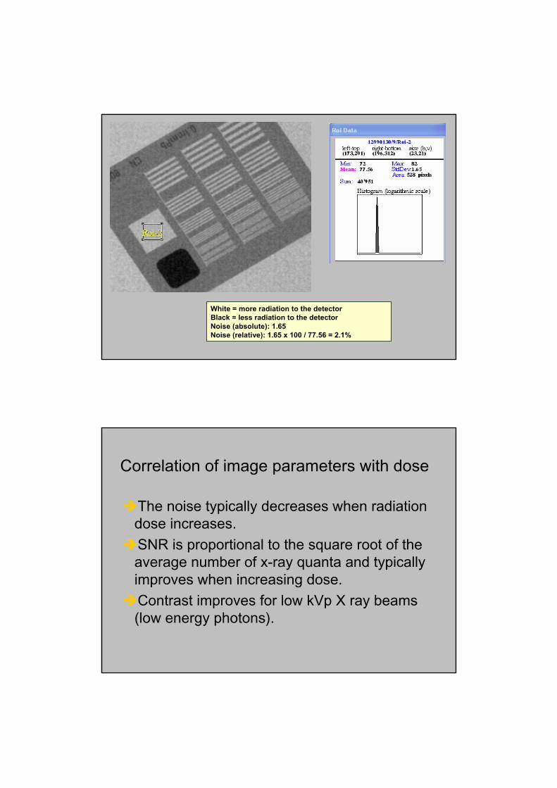
White = more radiation to the detectorBlack = less radiation to the detectorNoise (absolute): 1.65Noise (relative): 1.65 x 100 / 77.56 = 2.1%
Correlation of image parameters with dose
The noise typically decreases when radiationdose increases.
SNR is proportional to the square root of the average number of x-ray quanta and typically improves when increasing dose.
Contrast improves for low kVp X ray beams (low energy photons).

CR Agfa system:Left: 1mAs - 14 spatial resolution groupsRight: 100 mAs - 16 spatial resolution groups
Noise in a digital image produces poor spatial resolution and reduces contrast
1 mAs 100mAs
CR Agfa system:Left: 1mAs - 11 circles low contrastRight: 100 mAs -16 circles low contrast
1mAs 100 mAs

Relative dose level (Agfa system) 1.15 (image too noisy)
Relative dose level (Agfa system) 1.87 (image with enough quality) (with approx.
5 times more dose at the entrance)
Example of clinical images obtained with two different levels of dose and noise
Effect of the post-processing
The standard post-processing parameters offered in some CR workstations includes the noise reduction and the edge enhancement.
Some examples are shown for the Agfa post-processing called “MUSICA” (Multi Scale Image Contrast Enhancement). This is the basic principle of MUSICA:• contrast enhancement irrespective of feature size.
• difference with respect to spatial frequency band filtering.
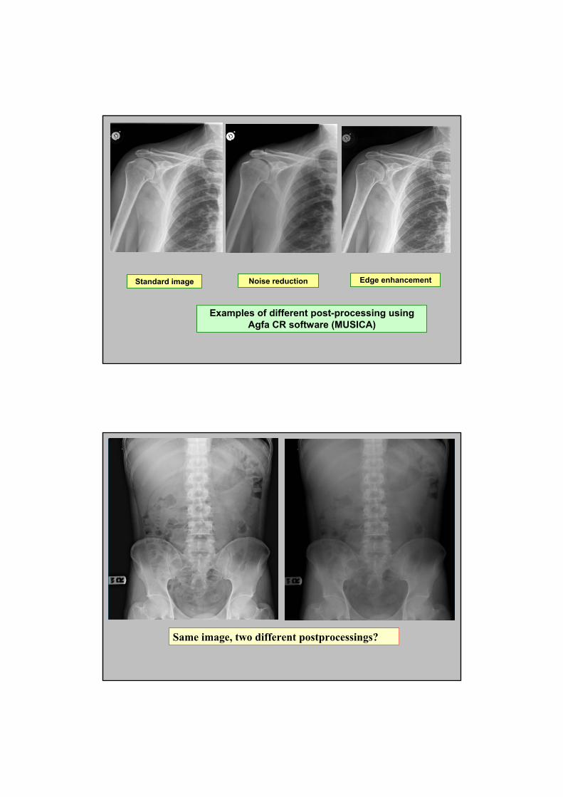
Standard image Noise reduction Edge enhancement
Examples of different post-processing using Agfa CR software (MUSICA)
Same image, two different postprocessings?
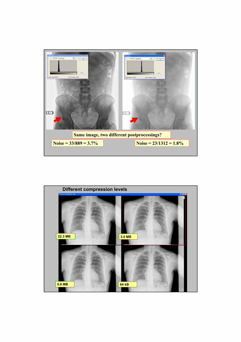
Same image, two different postprocessings?
Noise = 33/889 = 3.7% Noise = 23/1312 = 1.8%
22.3 MB 3.0 MB
0.8 MB 64 kB
Different compression levels

22.3 MB 3.0 MB
0.8 MB 64 kB
Patient DoseMore dose better image quality
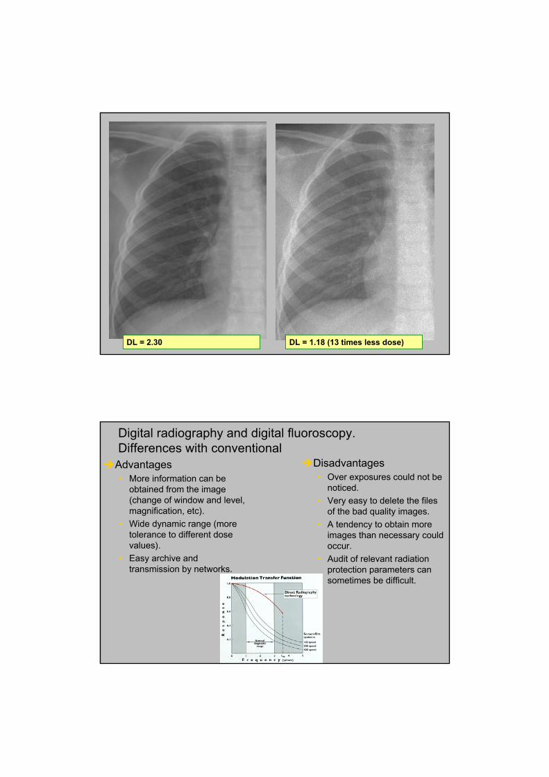
DL = 1.18 (13 times less dose)DL = 2.30
Advantages• More information can be
obtained from the image (change of window and level, magnification, etc).
• Wide dynamic range (more tolerance to different dose values).
• Easy archive and transmission by networks.
Disadvantages• Over exposures could not be
noticed.
• Very easy to delete the files of the bad quality images.
• A tendency to obtain more images than necessary could occur.
• Audit of relevant radiation protection parameters can sometimes be difficult.
Digital radiography and digital fluoroscopy. Differences with conventional
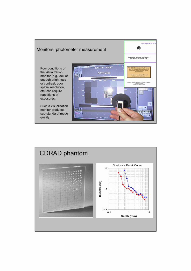
Monitors: photometer measurement
Poor conditions of the visualization monitor (e.g. lack of enough brightness or contrast, poor spatial resolution, etc) can require repetitions of exposures.
Such a visualization monitor produces sub-standard image quality.
CDRAD phantom
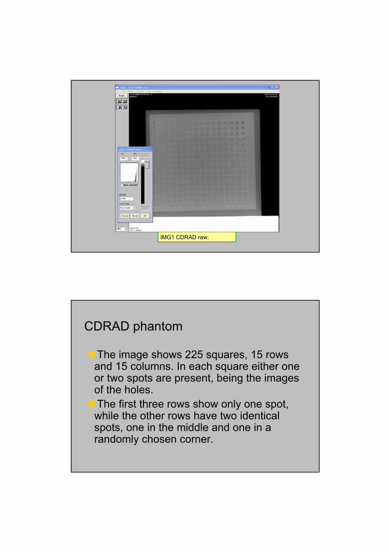
IMG1 CDRAD raw;
CDRAD phantom
The image shows 225 squares, 15 rows and 15 columns. In each square either one or two spots are present, being the images of the holes. The first three rows show only one spot, while the other rows have two identical spots, one in the middle and one in a randomly chosen corner.
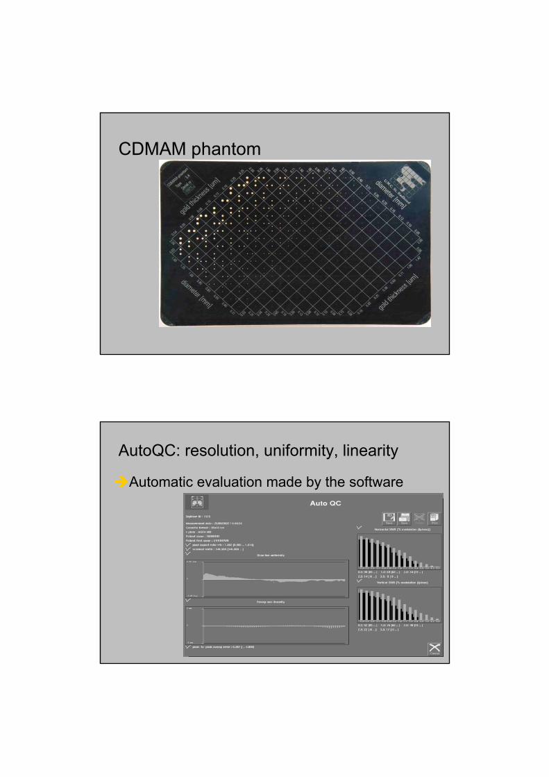
CDMAM phantom
AutoQC: resolution, uniformity, linearity
Automatic evaluation made by the software
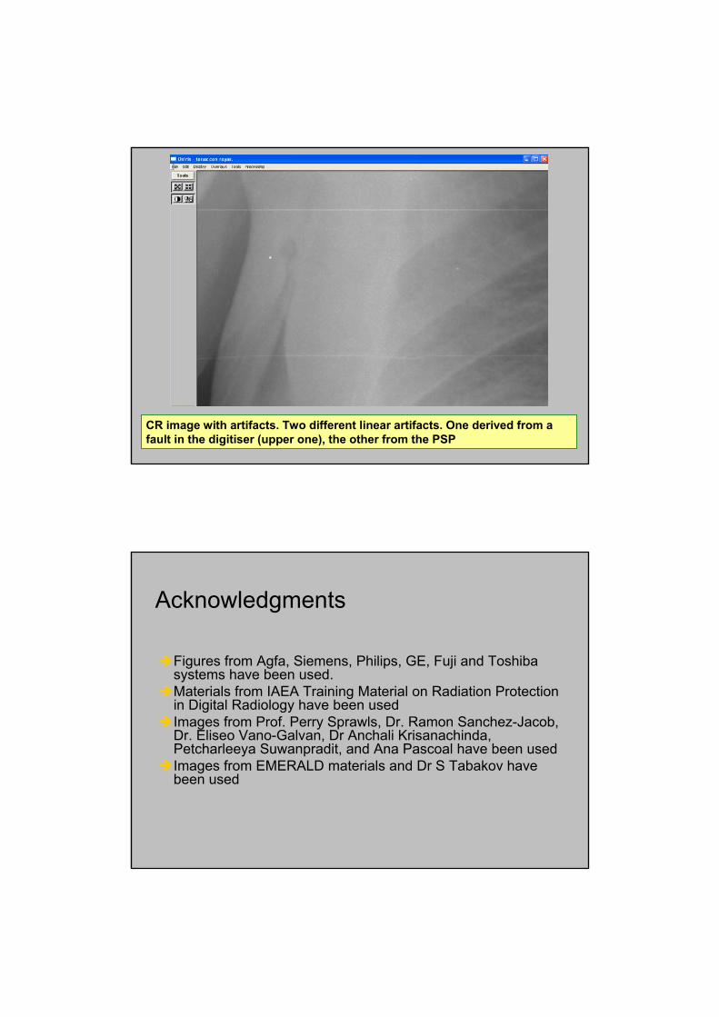
CR image with artifacts. Two different linear artifacts. One derived from a fault in the digitiser (upper one), the other from the PSP
Acknowledgments
Figures from Agfa, Siemens, Philips, GE, Fuji and Toshiba systems have been used.Materials from IAEA Training Material on Radiation Protection in Digital Radiology have been usedImages from Prof. Perry Sprawls, Dr. Ramon Sanchez-Jacob, Dr. Eliseo Vano-Galvan, Dr Anchali Krisanachinda, Petcharleeya Suwanpradit, and Ana Pascoal have been usedImages from EMERALD materials and Dr S Tabakov have been used