commander 501 user guide process controller · abb instrumentation ... manufacture of...
TRANSCRIPT
ABB Instrumentation
COMMANDER 501Process Controller
User Guide
50.1
50
COMMANDER 500
50.1
ABB INSTRUMENTATION
RE
GIS T E R E D F
IRM
BS EN ISO 9001
St Neots, U.K. – Cert. No. Q5907Stonehouse, U.K. – Cert. No. FM 21106
The CompanyABB Instrumentation is an established world force in the design andmanufacture of instrumentation for industrial process control, flowmeasurement, gas and liquid analysis and environmentalapplications.
As a part of ABB, a world leader in process automation technology,we offer customers application expertise, service and supportworldwide.
We are committed to teamwork, high quality manufacturing,advanced technology and unrivalled service and support.
The quality, accuracy and performance of the Company’s productsresult from over 100 years experience, combined with a continuousprogram of innovative design and development to incorporate thelatest technology.
The NAMAS Calibration Laboratory No. 0255(B) is just one of the tenflow calibration plants operated by the Company, and is indicative ofABB Instrumentation's dedication to quality and accuracy.
Health and SafetyTo ensure that our products are safe and without risk to health, the following points must be noted:
1. The relevant sections of these instructions must be read carefully before proceeding.
2. Warning labels on containers and packages must be observed.
3. Installation, operation, maintenance and servicing must only be carried out by suitably trained personnel andin accordance with the information given.
4. Normal safety precautions must be taken to avoid the possibility of an accident occurring when operating inconditions of high pressure and/or temperature.
5. Chemicals must be stored away from heat, protected from temperature extremes and powders kept dry.Normal safe handling procedures must be used.
6. When disposing of chemicals ensure that no two chemicals are mixed.
Safety advice concerning the use of the equipment described in this manual or any relevant hazard data sheets(where applicable) may be obtained from the Company address on the back cover, together with servicing andspares information.
Note.Clarification of an instruction or additionalinformation.
Information.Further reference for more detailed information ortechnical details.
Although Warning hazards are related to personal injury, and Caution hazards are associated with equipment orproperty damage, it must be understood that operation of damaged equipment could, under certain operationalconditions, result in degraded process system performance leading to personal injury or death. Therefore, complyfully with all Warning and Caution notices.
Information in this manual is intended only to assist our customers in the efficient operation of our equipment. Useof this manual for any other purpose is specifically prohibited and its contents are not to be reproduced in full orpart without prior approval of Technical Communications Department, ABB Instrumentation.
Stonehouse, U.K. – Cert. No. 0255
EN 29001 (ISO 9001)
Lenno, Italy – Cert. No. 9/90A
Use of Instructions
Warning.An instruction that draws attention to the risk ofinjury or death.
Caution.An instruction that draws attention to the risk ofdamage to the product, process or surroundings.
Licensing, Trademarks and CopyrightsMODCELL™ and PC-30™ are trademarks of Asea Brown Boveri, Inc.Modbus™ is a trademark of Modicon, Inc.IBM™ and IBM PC AT™ are trademarks of International Business Machines Corp.
GETTING STARTED
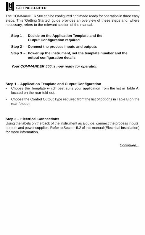
The COMMANDER 500 can be configured and made ready for operation in three easysteps. This 'Getting Started' guide provides an overview of these steps and, wherenecessary, refers to the relevant section of the manual.
Step 1 – Decide on the Application Template and theOutput Configuration required
Step 2 – Connect the process inputs and outputs
Step 3 – Power up the instrument, set the template number and theoutput configuration details
Your COMMANDER 500 is now ready for operation
Step 1 – Application Template and Output Configuration• Choose the Template which best suits your application from the list in Table A,
located on the rear fold-out.
• Choose the Control Output Type required from the list of options in Table B on therear foldout.
Step 2 – Electrical ConnectionsUsing the labels on the back of the instrument as a guide, connect the process inputs,outputs and power supplies. Refer to Section 5.2 of this manual (Electrical Installation)for more information.
Continued…

GETTING STARTED
Fig. GS.1 Setting the Parameters
Note. With theabove configuration, noalarms or limits havebeen set and advancedfunctionality (gainscheduling, set pointsources etc.) has notbeen enabled.
Step 3 – Setting the Parameters (Fig. GS.1)A Power-up the instrument. Press the and keys simultaneously and hold for
3 seconds to advance directly to Level 6 – Basic Configuration.
B Set the appropriate application template, output type and control action. Use the key to advance between frames and upper and keys to adjust the
default values – see Section 4.2 for further information.
Note. When the output type has been selected, the available inputs andoutputs default to the settings shown in Table B on the rear fold-out.
C If you are not using 4 to 20mA inputs, then select Level 7 using the upper and keys and set up Analog Inputs I/P1 to I/P3 to suit your process – see Section 4.3.
D Controller templates only:Select Level 2 using the upper and keys and set the tune parameters:• Analog or Motorized Valve Control – set the Proportional, Integral and
Derivative terms.• Time Proportioning Control – set the Cycle Time, Hysteresis and P, I & D Terms• Heat/Cool Outputs – set the points at which the Output 1 and Output 2
become active.
E Press to return to the Operating displays.
F Adjust the set point to the required value.
Your COMMANDER 500 is now in operation
APPLLEV.6
INPtLEV.7
tUNELEV2
B
C D
+
A
01.SLt.APP
ANLGO.tYP
rEVC.ACt
50FrEJ
E 50.1 50.5
50
50.1 50.5
50
F
50.1 50.5
50

1
OVERVIEW
Displays and Controls• Displays and Function Keys• LED Indication• Error Messages
Operator Mode (Level 1)• Single Loop Controller• Motorized Valve Controller• Auto/Manual &
Backup Stations
Set Up Mode (Levels 2 to 5)• Level 2 – Tuning• Level 3 – Set Points• Level 4 – Alarm Trip Points• Level 5 – Valve Setup
8
Configuration Mode (Levels 6 to E)• Level 6 – Basic Configuration• Level 7 – Input Configuration• Level 8 – Alarm Configuration• Level 9 – Set Point Configuration• Level A – Control Configuration• Level B – Operator Configuration• Level C – Output Configuration• Level D – Serial Communications• Level E – System Calibration
Installation• Siting• Mounting• Electrical Connections
GettingStarted
GettingStarted
Table A – Template ApplicationsB – Output Sources
Table C – Digital SourcesD – Analog Sources
Shunt Resistors2 x 100Ω
(+1 optional)
Process Labelsx3
Panel Clampsx2
CJ Sensorx1
(+1 optional)
This manual is divided into 5 sections which contain all the information needed to install, configure,commission and operate the COMMANDER 501 Process Controller. Each section is identifiedclearly by a symbol as shown in Fig. 1.
Fig. 1 Overview of Contents
Fig. 2 Foldouts
Fig. 3 Accessories

2
CONTENTS
Section Page
OVERVIEW ................................................... 1
CONTENTS ................................................... 2
1 DISPLAYS AND FUNCTION KEYS ........ 31.1 Introduction ....................................... 31.2 Use of Function Keys ....................... 41.3 Secret-til-Lit Indicators ..................... 81.4 Character Set ................................... 81.5 Error Messages ................................ 91.6 Processor Watchdog ...................... 101.7 Loop Break Monitor ........................ 101.8 Glossary of Abbreviations .............. 10
2 OPERATOR LEVEL .............................. 112.1 Introduction ................................... 112.2 Single Loop Controller
(Templates 1 and 2) ....................... 122.3 Auto/Manual Station
(Templates 3 and 4) ....................... 142.4 Analog Backup
(Templates 5 and 6) ....................... 162.5 Indicator/Manual Loader Station
(Templates 7 and 8) ....................... 182.6 Heat/Cool Output Types ............... 192.7 Motorized Valve Output Types ...... 202.8 Auto-tune ....................................... 212.9 Control Efficiency Monitor ............. 24
3 SET UP MODE ...................................... 273.1 Introduction ................................... 273.2 Level 2 – Tune .............................. 283.3 Level 3 – Set Points ...................... 323.4 Level 4 – Alarm Trip Points ........... 343.5 Level 5 – Valve Setup ................... 35
4 CONFIGURATION MODE ..................... 384.1 Introduction ................................... 384.2 Level 6 – Basic Configuration ....... 394.3 Level 7 – Analog Inputs ................ 434.4 Level 8 – Alarms ........................... 474.5 Level 9 – Set Point Configuration . 514.6 Level A – Control Configuration .... 544.7 Level B – Operator Configuration . 594.8 Level C – Output
Assignment Configuration ............. 614.9 Level D – Serial
Communications Configuration ..... 674.10 Level E – Calibration ..................... 68
Section Page
5 INSTALLATION ..................................... 715.1 Mechanical Installation ................. 715.2 Electrical Installation ..................... 765.3 Relays ........................................... 785.4 Digital Output ................................ 785.5 Control or Retransmission
Analog Output ................................ 785.6 Motorized Valve Connections ....... 795.7 Input Connections ......................... 795.8 Output Connections ...................... 805.9 Power Supply Connections ........... 80
APPENDIX A – CONTROL TEMPLATES .. 81A1 Single Loop Controller
(Templates 1 and 2) ....................... 81A2 Auto/Manual Station and
Analog Backup Station .................. 82A3 Indicator/Manual Loader Station
(Templates 7 and 8) ....................... 85B3 Four Programmable Maths Blocks 86
APPENDIX B – COMMANDERCONFIGURATION EDITOR ........................ 86
B1 Introduction .................................... 86B2 Analog Input Customization .......... 86B4 Six Logic Equations ....................... 86B5 Process Alarm Customization ....... 86B6 Two Real Time Alarms ................... 86B7 Two Delay Timers .......................... 87B8 Two Custom Linearizers ................ 87B9 Template Customization ................ 87B10 Connecting the
COMMANDER PC Configurator ... 87
FRAMES INDEX ......................................... 88
INDEX ........................................................ 91
NOTES ........................................................ 94
3
1 DISPLAYS AND FUNCTION KEYS
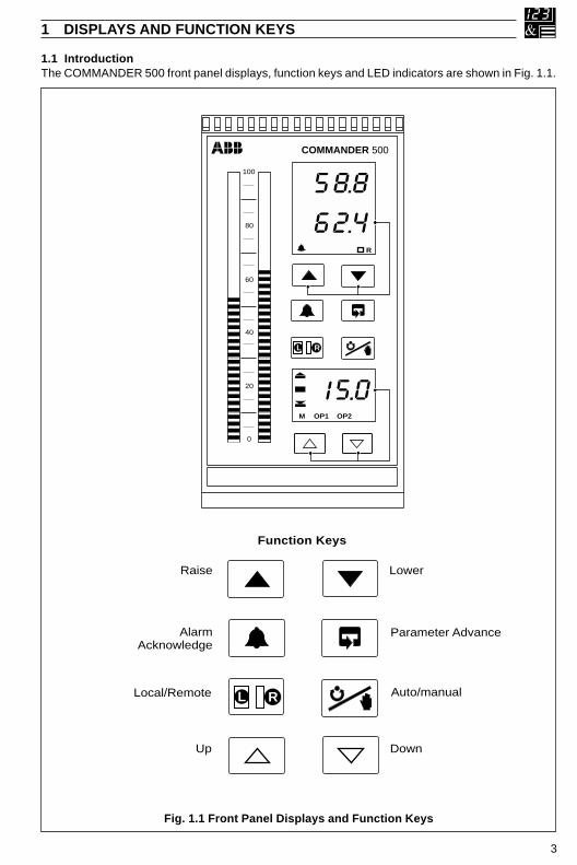
1.1 IntroductionThe COMMANDER 500 front panel displays, function keys and LED indicators are shown in Fig. 1.1.
Fig. 1.1 Front Panel Displays and Function Keys
Function Keys
Auto/manual
Raise
Local/Remote L LR
Parameter AdvanceAlarmAcknowledge
Lower
Up Down
100
80
60
40
20
0
M OP1 OP2
COMMANDER 500
58.8
62.4
15.0
L LR
R
4
…1 DISPLAYS AND FUNCTION KEYS
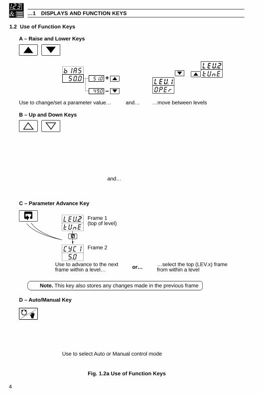
1.2 Use of Function Keys
Fig. 1.2a Use of Function Keys
D – Auto/Manual Key
Use to select Auto or Manual control mode
A – Raise and Lower Keys
Use to change/set a parameter value… …move between levelsand…
C – Parameter Advance Key
Use to advance to the nextframe within a level… or… …select the top (LEV.x) frame
from within a level
Note. This key also stores any changes made in the previous frame
LEV2tUnE
CYCl 5.0
Frame 2
Frame 1(top of level)
B – Up and Down Keys
and…
bIAS 50.0 51.0
49.0
+
–LEV1OPEr
LEV2tUnE
…move between frames within a Setupor Configuration level. Any changes madeon the current frame are stored when thenext frame is selected.
LEV2tUnE
CYCl 5.0
Frame 2
Frame 1(top of level)
Press and hold
LEVx100110021003
Use to adjust the output value…
700 710
690
+
–
450.2500.0
70
Auto Manual450.2500.0
70
Process VariableControl Set Point
Control Output (%)
M
2.00
2.01

5
1 DISPLAYS AND FUNCTION KEYS…
…1.2 Use of Function Keys
Fig. 1.2b Use of Function Keys
E – Alarm Acknowledgement
Any active,unacknowledged alarms
All active alarmsacknowledged
(Flashing)
450.2500.0
70
200.31.HP1
20031HP1
ACt
ACK
LAt
or
CLr
ACK
LAtor
200.32.xxx
ACt
1
2 3
4
Unacknowledgedalarms only
450.2500.0
70
(On continuously) (Off)
No activealarms present
Pressing again acknowledges the displayed alarm.Lower display changes to reflect new status.
3
Next active and unacknowledged alarm is displayed. If no alarmsare active, the next enabled alarm is displayed.
4
The lower display shows alarm status:ACt Alarm active and unacknowledgedACK Alarm active and acknowledgedCLr Cleared or Inactive alarmLAt Unacknowledged latched alarm
2
High Process, PV High Output Low Process, PV Low Output High Latch, PV Power Failure Time Low Latch, PV Maths Block 1 High High Deviation Maths Block 1 Low Low Deviation Maths Block 2 High High Process I/P1 Maths Block 2 Low Low Process I/P1 Maths Block 3 High High Process I/P2 Maths Block 3 Low
Low Process I/P2 Maths Block 4 HighHigh Process I/P3 Maths Block 4 LowLow Process I/P3
The first active and unacknowledged alarm is displayed(or if no alarms are active, the first enabled alarm is displayed)
1
HPV HO LPV LOHLP PF.tLLP Hb1Hd Lb1Ld Hb2HP1 Lb2LP1 Hb3HP2 Lb3LP2 Hb4HP3 Lb4LP3
Note. The time of the power failure,PF.t, is shown in the set point display.
Note. If no alarms have been enabled in the Set Up level, pressingthe key has no effect.
6
…1 DISPLAYS AND FUNCTION KEYS
…1.2 Use of Function Keys
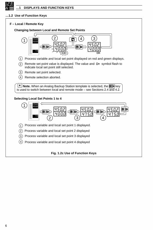
Fig. 1.2c Use of Function Keys
F – Local / Remote Key
Changing between Local and Remote Set Points
Selecting Local Set Points 1 to 4
Process variable and local set point 2 displayed
450.2350.0
70400.0450.2
475.0450.2
2 43
L LR
Process variable and local set point 1 displayed.1
1
2
Process variable and local set point 3 displayed3
Process variable and local set point 4 displayed
L LR
475.0450.2
L LR
4
L LR
450.2500.0
70400.0450.2
400.0450.2
2 4 3
L LR
R
L LR
1
4
Remote set point value is displayed. The value and symbol flash toindicate local set point still selected.
Process variable and local set point displayed on red and green displays.1
2
Remote set point selected.3
Remote selection aborted.
R
Note. When an Analog Backup Station template is selected, the keyis used to switch between local and remote mode – see Sections 2.4 and 4.2.
L LR
R
7
1 DISPLAYS AND FUNCTION KEYS…
…1.2 Use of Function Keys
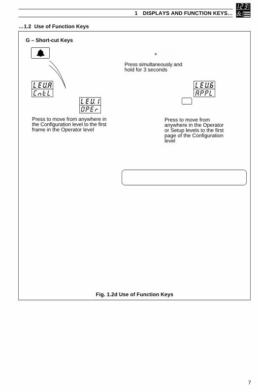
Fig. 1.2d Use of Function Keys
G – Short-cut Keys
Press to move from anywhere inthe Configuration level to the firstframe in the Operator level
Press to move fromanywhere in the Operatoror Setup levels to the firstpage of the Configurationlevel
LEVACntL
LEV1OPEr
LEV6APPL
Press simultaneously andhold for 3 seconds
+
450.2350.0
70
450.2350.0
70
Press and hold to move from the Operator Level tothe Security Code Frame and then to other levels:
Tune Level – See Section 2.13.3Set Up Level – See Fig. 3.1Configuration Level – See Fig. 4.1
COdE 0
Note. This short-cut key operates only whenthe Configuration password is set to ‘0’.
8
…1 DISPLAYS AND FUNCTION KEYS
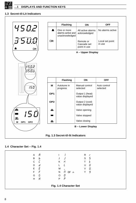
1.3 Secret-til-Lit Indicators
1.4 Character Set – Fig. 1.4
Fig. 1.3 Secret-til-lit Indicators
Fig. 1.4 Character Set
M
OP1
OP2
OFF
Auto controlselected
ON
Manual controlselected
Output 1 (heat)value displayed
Output 2 (cool)value displayed
Valve opening
Valve stopped
Valve closing
Flashing
Autotune inprogress
OFF
No alarms active
Local set pointin use
ON
All active alarmsacknowledged
Remote orCascade setpoint in use
Flashing
One or morealarms active andunacknowledged
A – Upper Display
B – Lower Display
450.2350.0
150
M OP1 OP2
150
R
450.2
350.0 R
ABCDEFGH
IJKLMNOP
RSTUVY
AbCdEFGH
IJKLMN or nOP
rStUVY
9
1 DISPLAYS AND FUNCTION KEYS…
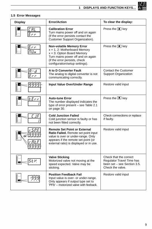
1.5 Error Messages
70
70
70
70
70
70
70
Error/Action
Calibration ErrorTurn mains power off and on again(if the error persists contact theCustomer Support Organization).
Non-volatile Memory Errorx = 1, 2: Motherboard Memoryx = 3: Option Board MemoryTurn mains power off and on again(if the error persists, checkconfiguration/setup settings).
A to D Converter FaultThe analog to digital converter is notcommunicating correctly.
Input Value Over/Under Range
Auto-tune ErrorThe number displayed indicates thetype of error present – see Table 2.1on page 30.
Cold Junction FailedCold junction sensor is faulty or hasnot been fitted correctly.
Remote Set Point or ExternalRatio Failed. Remote set point inputvalue is over or under-range. Onlyappears if the remote set point (orexternal ratio) is displayed or in use.
Valve StickingMotorized valve not moving at thespeed expected. Valve may besticking.
Position Feedback FailInput value is over- or under-range.Only appears if output type set to'PFb' – motorized valve with feeback.
To clear the display:
Press the key
Press the key
Contact the CustomerSupport Organization
Restore valid input
Press the key
Check connections or replaceif faulty.
Restore valid input
Check that the correctRegulator Travel Time hasbeen set – see Section 3.5.Check the valve.
Restore valid input
Display
CALErr
9999
t.Err 1
StK
A-dErr
ErrNVx
CJ.F 1
rSP.F9999
rAt.F9999
or
999

10
…1 DISPLAYS AND FUNCTION KEYS
1.6 Processor WatchdogThe instrument’s processor activity is monitored by an independent watchdog device. When theoutput of the watchdog is assigned to a relay or digital output, the relay/digital output de-energizesif the instrument fails to function correctly.
1.7 Loop Break MonitorBoth analog outputs are monitored continuously to detect a loop break. A warning signal or otheraction can be initiated by assigning the loop break signals to relays or digital outputs.
1.8 Glossary of Abbreviations
Table 1.1 Glossary of Abbreviations
noitaiverbbA noitpircseD noitaiverbbA noitpircseD
VP elbairaVssecorP 1id 1tupnIlatigiD
tPSL eulaVtnioPteSlacoL 2id 2tupnIlatigiD
1PSL eulaV1tnioPteSlacoL 3id 3tupnIlatigiD
2PSL eulaV2tnioPteSlacoL 4id 4tupnIlatigiD
3PSL eulaV3tnioPteSlacoL 1oa 1tuptuOgolanA
4PSL eulaV4tnioPteSlacoL 2oa 2tuptuOgolanA
tPSC eulaVtnioPteSlortnoC 1od 1tuptuOlatigiD
tPSR eulaVtnioPteSetomeR 2od 2tuptuOlatigiD
P/ODIP mhtiroglADIPehtfotuptuO
1PO )taeh(1tuptuOrellortnoC
2PO )looc(2tuptuOrellortnoC
1P/I 1tupnIgolanA
2P/I 2tupnIgolanA
3P/I 3tupnIgolanA
11
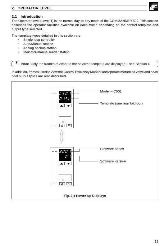
2.1 IntroductionThe Operator level (Level 1) is the normal day-to-day mode of the COMMANDER 500. This sectiondescribes the operator facilities available on each frame depending on the control template andoutput type selected.
The template types detailed in this section are:• Single loop controller• Auto/Manual station• Analog backup station• Indicator/manual loader station
Note. Only the frames relevant to the selected template are displayed – see Section 4.
In addition, frames used to view the Control Efficiency Monitor and operate motorized valve and heat/cool output types are also described.
2 OPERATOR LEVEL
Fig. 2.1 Power-up Displays
C50101.SL
200101
Model – C501
Template (see rear fold-out)
Software series
Software version

12
…2 OPERATOR LEVEL
Fig. 2.2 Single Loop Controller
2.2 Single Loop Controller (Templates 1 and 2)The single loop controller is a basic feedback control system using three-term PID or on/off controlwith either a local set point (template 1) or remote set point (template 2).
PIDControl Loop
PID O/PCSPt
I/P2
PVI/P1
Manual Output
OP1
Remote Set Point Input
Process Variable Input
•1 Template 2 Only
•1
LSPt
I/P2 x rAtO + bIAS
RSPt
L LRLocal Set Point
ControlOutput

13
450.2500.0
rAtO1.000
Set Point
ProcessVariable
70
Set Point
ProcessVariable
OP1
70
OP1
•2
•1
bIAS1.000
Set Point
ProcessVariable
70
OP1
•3
•1
2 OPERATOR LEVEL…
Process Variable
Control Set Point['SPLO' to 'SPHI' – see Section 4.5]Adjustable in Local Control Only
Control Output[0 to 100% (digital/relay outputs),–10 to 110% (analog outputs)]Adjustable in manual mode only. With on/off controlselected, 0% = control output off, 100% = controloutput on. In manual mode, intermediate values canbe selected. These use ‘time proportioning’ with a60s cycle time, e.g. 25% = 15s on, 45s off.
Remote Set Point Ratio
[0.001 to 9.999]Remote set point value =(ratio x remote set point input) + bias
Remote Set Point Bias
[In engineering units]
Return to top of page
•1 With the Ramping Set Point function enabled (see Section 3.3, Set Points/ Ramp Rate), thebargraph shows the actual (ramping) set point value and the digital display shows the target set pointvalue.
•2 Only displayed if template 2 selected and Ratio Display is enabled – see Section 4.2, BasicConfiguration and Section 4.7, Operator Configuration.
•3 Only displayed if template 2 selected and Bias Display is enabled – see Section 4.2, BasicConfiguration and Section 4.7, Operator Configuration.
…2.2 Single Loop Controller (Templates 1 and 2)

14
…2 OPERATOR LEVEL
2.3 Auto/Manual Station (Templates 3 and 4)
Fig. 2.3 Auto/Manual Station
di1
Master Outputao1
•1
•2
•1 Template 3 Only•2 Template 4 Only
Digital Select
I/P2
Manual Output
Low Signal Select(Alarm A1)
Auto / ManualSelect
Analog Output
Note. Refer also to Appendix A2.1 – Series and Parallel Operation.
The auto/manual station provides a backup for a master controller. In normal operation theCOMMANDER 500’s analog output follows the master controller’s output value. A fault in the mastersystem can be identified either by detecting a low signal on the master output (template 3) or via adigital signal (template 4). When a fault is detected the COMMANDER 500 goes into manual modewith its output either set to the last valid master output value or to a configured output value – seeSection 4.6, Control Configuration/ Configured Output 1. When the master output is restored or thedigital input returns to its inactive state, the COMMANDER 500 switches back to auto mode.
Note. The Alarm A1 Trip value must be set when using template 3.

15
55.050.0
Masteroutput
ProcessVariable
70
55.5 50.0
50
M
MasteroutputProcessVariable
orLow MasterOutput Value
Digital InputActive
or
•1
•2
•3
orRestoredMaster Output
Digital InputInactive
or
•1
•2
•3
•1 In template 4 the Auto/Manual switch is overridden by the digital input signal.
•2 Template 3 only – see Section 4.2, Basic Configuration/ Template Application.
•3 Template 4 only – see Section 4.2, Basic Configuration/ Template Application.
Auto Mode
Process VariableMaster Output (I/P2)
Control Output = Master Output[Master Output, 0 to 100%]
Manual Mode
Control Output (under COMMANDER 500 control)[0 to 100%]
2 OPERATOR LEVEL…
…2.3 Auto/Manual Station (Templates 3 and 4)

16
…2 OPERATOR LEVEL
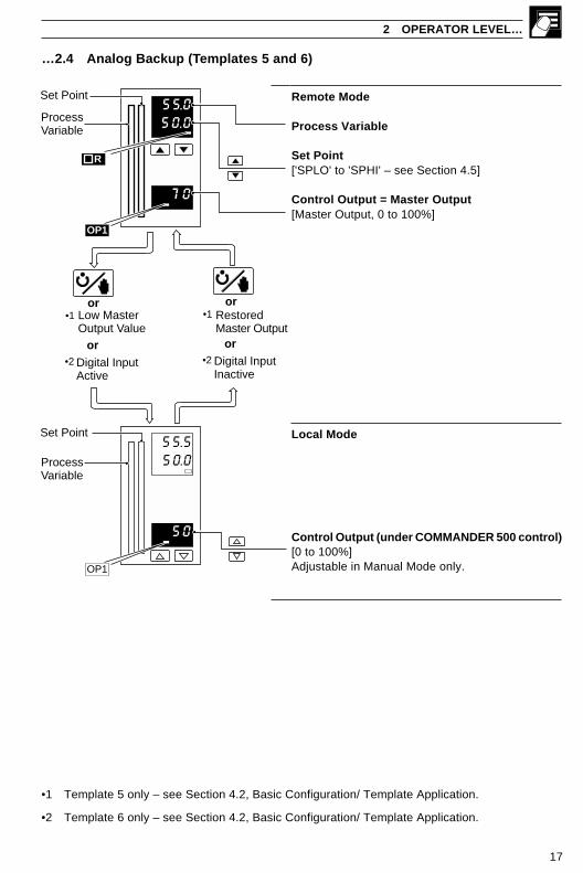
2.4 Analog Backup (Templates 5 and 6)
Fig. 2.4 Analog Backup Station
LSPt
I/P1
di1
Local Set Point
PVProcess Variable
PIDControl Loop
Local/RemoteSelect
•1
•1 Template 5 Only•2 Template 6 Only
Master Output
Digital Select
ao1
Manual Output
Low Signal Select(Alarm 1)
L LR
Analog Output
I/P2
•2
Note. Refer also to Appendix A2.1 – Series and Parallel Operation.
The analog backup station provides a backup for a master controller. In normal operation (remotecontrol mode selected) the COMMANDER 500’s current output follows the master controller’s outputvalue. A fault in the master system can be identified either by detecting a low signal on the masteroutput (template 5) or via a digital signal (template 6). When a fault is detected the COMMANDER500 switches into local control mode and the process is controlled by the PID output of theCOMMANDER 500. The COMMANDER 500 PID algorithm tracks the master output valuecontinuously in order to ensure bumpless transfer from remote to local mode operation. When themaster output is restored or the digital input returns to its inactive state, the COMMANDER 500switches back to remote control mode.
Note. The Alarm A1 Trip value must be set when using template 5.
17
Remote Mode
Process Variable
Set Point['SPLO' to 'SPHI' – see Section 4.5]
Control Output = Master Output[Master Output, 0 to 100%]
Local Mode
Control Output (under COMMANDER 500 control)[0 to 100%]Adjustable in Manual Mode only.
2 OPERATOR LEVEL…
…2.4 Analog Backup (Templates 5 and 6)
•1 Template 5 only – see Section 4.2, Basic Configuration/ Template Application.
•2 Template 6 only – see Section 4.2, Basic Configuration/ Template Application.
55.050.0
Set Point
ProcessVariable
70
OP1
R
55.5 50.0
50
OP1
Set Point
ProcessVariable
orRestoredMaster Output
Digital InputInactive
or
•1
•2
orLow MasterOutput Value
Digital InputActive
or
•1
•2

18
…2 OPERATOR LEVEL
2.5 Indicator/Manual Loader Station (Templates 7 and 8)One or two process variables can be displayed on the digital and bargraph displays. If the controloutput is assigned to an analog output the lower display indicates its value which can be adjusted bythe user.
•1 Only displayed if template 8 selected – see Section 4.2, Basic Configuration/Template Application.
•2 Only displayed if control output type is 'analog' (output is assigned to Analog Output 1).
Process Variable PV1
Process Variable PV2
Output Value[–10 to 110%]
55.050.0
ProcessVariable(PV2)
ProcessVariable(PV1)
50
OP1
•1
•1
•2

19
2 OPERATOR LEVEL…
2.6 Heat/Cool Output Types2.6.1 Reverse (Heat)/Direct (Cool) or Direct (Heat)/Reverse (Cool)The active output, either OP1 (Heat) or OP2 (Cool) is displayed and may be adjusted in manualmode. The OP1 and OP2 l.e.d.s indicate which output is changing.
Output Positive (Heat Output Active)
Heat Output[0 to 100% (0 to 110% in manual mode with analogoutputs)]Adjustable in manual mode only.
Output Negative (Cool Output Active)
Cool Output[–100 to 0% (–110 to 0% in manual mode withanalog outputs)]Adjustable in manual mode only.
Fig. 2.5 Typical Response – Reverse/Direct or Direct/Reverse Control Action
OP2 (cool) OP1 (heat)
Y2.St Y1.St PID O/P
0%
–100%
100%
+100%
450.2500.0
50
OP1
–50
OP2

20
…2 OPERATOR LEVEL
2.6.2 Reverse (Heat)/Reverse (Cool) or Direct (Heat)/Direct (Cool)It is not possible to view or adjust the heat/cool outputs directly. The PID output (0 to 100%), used tocalculate the heat (OP1) and cool (OP2) outputs, is displayed and may be adjusted in manual mode.The OP1 and OP2 l.e.d.s indicate which output is changing.
2.7 Motorized Valve Output Types2.7.1 Motorized Valve with Feedback
Valve Position Display
[0 to 100% of travel]
Note. In manual mode, the and keyscan be used to drive the valve open and valve closerelays directly.
2.7.2 Motorized Valve without Feedback (Boundless)
Valve State Display
OPN Valve openingStP Valve stoppedCLS Valve closing
Note. In manual mode, the and keyscan be used to drive the valve open and valve closerelays directly.
Fig. 2.6 Typical Response – Reverse/Reverse or Direct/Direct Control Action
OP2(cool)
OP1(heat)
Y2.St Y1.St PID O/P
OP2 l.e.d. lit OP1 l.e.d. lit
100%
0%0%
100%
450.2500.0
75
StP
Valve openingValve stoppedValve closing
Valve openingValve stoppedValve closing
21
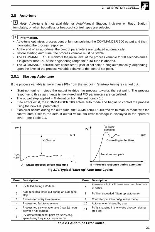
2.8 Auto-tune
Note. Auto-tune is not available for Auto/Manual Station, Indicator or Ratio Stationtemplates, or when boundless or heat/cool control types are selected.
Information.• Auto-tune optimizes process control by manipulating the COMMANDER 500 output and then
monitoring the process response.• At the end of an auto-tune, the control parameters are updated automatically.• Before starting auto-tune, the process variable must be stable.• The COMMANDER 500 monitors the noise level of the process variable for 30 seconds and if
it is greater than 2% of the engineering range the auto-tune is aborted.• The COMMANDER 500 selects either 'start-up' or 'at set point' tuning automatically, depending
upon the level of the process variable relative to the control set point.
2.8.1 Start-up Auto-tune
If the process variable is more than ±10% from the set point, 'start-up' tuning is carried out.
• 'Start-up' tuning – steps the output to drive the process towards the set point. The processresponse to this step change is monitored and PID parameters are calculated.
• The output step applied = % deviation from the set point x 1.5.• If no errors exist, the COMMANDER 500 enters auto mode and begins to control the process
using the new PID parameters.• If an error occurs during the auto-tune, the COMMANDER 500 reverts to manual mode with the
control output set to the default output value. An error message is displayed in the operatorlevel – see Table 2.1.
2 OPERATOR LEVEL…
Table 2.1 Auto-tune Error Codes
Fig 2.7a Typical 'Start-up' Auto-tune Cycles
+2%– 2%
tA – Stable process before auto-tune
SPT
PV
B – Process response during auto-tunet
PV1/4 wavedamping
Controlling to Set Point
Auto-tune complete
SPT
>10% span
rorrE noitpircseD rorrE noitpircseD
1 enut-otuagniruddeliafVP 7tuodetaluclacsaweulavDroI,PtnatluserA
egnarfo
2enut-otuanagnirudtuodemitsahenut-otuA
pets8 )enut-otua'putratS'(dedeecxetimilVP
3 enut-otuaotysionootssecorP 9 edomnoitarugifnocotnituprellortnoC
4 enut-otuaottsafootssecorP 01 resuybdetanimretenut-otuA
5sruoh21xam(enut-otuaotwolsootssecorP
.)selcyc-flahneewteb11
gnirudnoitceridgnorwehtnignignahcsiVPtsetpets
6.gne%52>ybtnioptesmorfdetaivedVP
tsetesnopserycneuqerfgnirudnaps

22
…2 OPERATOR LEVEL
Note. The time taken to complete auto-tune depends upon the system response time.
Note. Time Proportioning – the cycle time must be set prior to running an auto-tune. Thecycle time is not changed by the auto-tune.
2.8.2 'At Set Point' Auto-tuneIf the process variable is within 10% of the set point, 'at set point' tuning is carried out.
• 'At set point' tuning – manipulates the control output to produce a controlled oscillation of theprocess.
• A step change of ±10% of the starting output value is applied initially. This is adjusted to give anamplitude of oscillation 3 times the noise level.
• Once the amplitude and period of oscillation are consistent (minimum 2 cycles, maximum 4cycles) PID parameters are calculated.
• If no errors exist the controller enters auto mode and begins to control the process using the newPID parameters.
• If an error occurs during the auto-tune, the controller reverts to manual mode with the controloutput set to the default output value. An error message is displayed in the operator level –see Table 2.1.
Fig 2.7b Typical 'At Set Point' Auto-tune Cycles
t
SPT
PV
Auto-tunecomplete
Controlling toSet Point
B – Process response during auto-tune
+2%– 2%
t
PV
A – Stable process before auto-tune
SPT
< ±10 span
12 hours max.

23
2.8.3 Auto-tune
Accessing the Auto-tune FacilityFrom any operating frame, press and hold the keyuntil the 'COdE' frame is displayed.
Set the correct auto-tune password.
Auto-tune EnableSelect the type of auto-tune required.
Single Loop TemplatesOFF – OffA – Type Ab – Type B
Auto-tune is started automatically when the key ispressed.
Auto-tune can be stopped at any time by pressing the key.
Note. P + I control only – set the derivative termto 'OFF' in the Tuning Level – see Section 3.2.
Return to the Operating Level.
2 OPERATOR LEVEL…
Fig. 2.8 Autotune Types
Set Point
PV
14
=
Type A – 1/4 wave damping Type B – Minimum Overshoot
Set Point
PVx1
x2
x1
x2
1.xx
1COdE
1.xx
OFFAtNE
1..xx
xxxxxxxx
xxxxxxxx

24
…2 OPERATOR LEVEL
2.9 Control Efficiency Monitor
The Control Efficiency Monitor can be used either to compare the relative performance with differenttuning parameters, or when fine tuning the PID settings, to give optimum control.
When the set point is changed, auto mode is selected or following a power failure, input failure or alarge load disturbance, the control monitor performs a series of measurements to indicate theeffectiveness of the current control parameters.
General guidelines are shown in Table 2.2.
Table 2.2 Control Efficiency Monitor Settings
Action
• Decrease proportional band• Decrease integral time• Increase derivative time
• Increase proportional band• Increase derivative time
• Increase proportional band• Increase integral time
• Increase proportional band• Decrease integral time
If large overshoot andoscillatory then:• Increase proportional band• Increase integral time• Increase derivative time
If slow approach andoverdamped then:• Decrease proportional band• Decrease integral time
IdealSetting
Fast
Small
Small
Short
Small
Parameter
Rate ofApproach
Overshoot
Decay Ratio
Settling Time
Error Integral
ActualSetting
Too slow
Too large
Too large(Oscill-atory)
Too long
Too large
Effect on Response

25
…2.9 Control Efficiency Monitor
Fig. 2.9 Control Efficiency Monitor Parameters
2.9.1 Manual TuningThe Control Efficiency Monitor may be used for manually tuning the PID parameters. The followingmethod describes how to tune the controller for 1/4 wave damping:
a) Set the integral and derivative action times to OFF.
b) Set the proportional band (PB) to a low setting.
c) Apply a small set point change.
d) Use the Control Efficiency Monitor to note the decay ratio.
e) If the decay ratio > 0.25, increase the Proportional Band until decay ratio = 0.25
If the decay ratio < 0.25, decrease the Proportional Band until decay ratio = 0.25
f) Leave the proportional band at the setting which gives 0.25 decay ratio and, using the ControlEfficiency Monitor, note the period between peaks.
g) Calculate and set the following parameters:Integral action time = Period/1.5Derivative action time = Period/6
Note. The manual tuning facility must not be used with boundless motorized valve control, asan Integral Action Time is required for these applications.
2 OPERATOR LEVEL…
Set Point
x1 x2
y1y2
95%
5%
tperiodPV
Start ofCalculation
t
+2%
–2%
tsettle
tapproach
26
…2 OPERATOR LEVEL
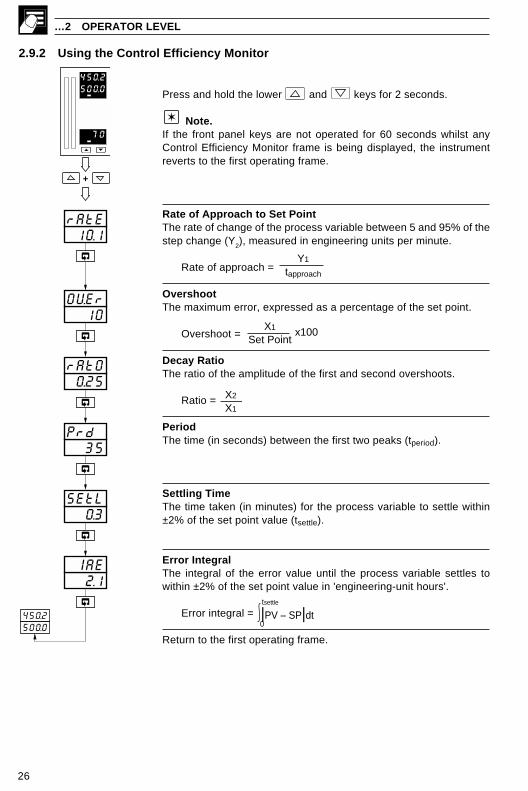
2.9.2 Using the Control Efficiency Monitor
Press and hold the lower and keys for 2 seconds.
Note.If the front panel keys are not operated for 60 seconds whilst anyControl Efficiency Monitor frame is being displayed, the instrumentreverts to the first operating frame.
Rate of Approach to Set PointThe rate of change of the process variable between 5 and 95% of thestep change (Y2), measured in engineering units per minute.
Rate of approach =
OvershootThe maximum error, expressed as a percentage of the set point.
Overshoot =
Decay RatioThe ratio of the amplitude of the first and second overshoots.
Ratio = X2
X1
PeriodThe time (in seconds) between the first two peaks (tperiod).
Settling TimeThe time taken (in minutes) for the process variable to settle within±2% of the set point value (tsettle).
Error IntegralThe integral of the error value until the process variable settles towithin ±2% of the set point value in 'engineering-unit hours'.
Error integral = |PV – SP|dt0
tsettle
Return to the first operating frame.
+
10.1rAtE
10OVEr
450.2500.0
70
0.25rAtO
35Prd
0.3SEtL
2.1 IAE
450.2500.0
Y1
tapproach
X1
Set Pointx100

27
83 SET UP MODE
3.1 IntroductionTo access the Set Up mode (Levels 2 to 5) the correct password must be entered in the security code frame.
Fig. 3.1 Set Up Mode – Overview
Fig. 3.2 – Scroll Display Overview
450.2500.0
70
450.2500.0
70
50COdE
OFFAtNE LEV1
OPEr
LEV2LEV5
tUNEVLVE
LEV1OPEr
Valid Set Up orConfigurationpassword
LEV2 TuningCycle time, output 1 & 2On/off hysteresis valuesProportional bands 1 to 4Integral action times 1 to 4Derivative action times 1 & 2Manual reset valueControl deadbandHeat Cool Output 1 & 2 Start
LEV3 Set PointsLocal set point values 1 to 4Slave set point valueRemote set point ratio/biasRamp rate
LEV4 Alarm Trip PointsAlarm 1 to 8 trip points
LEV5 Motorized Valve Set UpWith feedback:
Feedback ratio/biasDeadbandRegulator travel time
Boundless:DeadbandRegulator travel time
Pressand hold
Invalidpassword
450.2500.0
2.00
450.2500.0
2.00
tUNELEV.2
1.0CYC.12.01
Frame number2.xx – Level 23.xx – Level 3 etc.
Parameter
Parameteradjustment
450.2500.0
2.00
2.00
Defaultvalue

28
82.00...2.04
…3 SET UP MODE
3.2 Level 2 – Tune
Note. Level 2 is not applicable if an Auto/Manual Station or Indicator template is selected.
•1 Only displayed if Relay or Digital output type is selected – see Section 4.2, Basic Configuration/ Output Type.
•2 Only displayed if Heat/Cool output type is selected.
•3 Only if On/Off control is selected – see parameters 2.01 and 2.02 above.
•4 Only displayed if Heat/Cool output type is select and the 'CYC.2' parameter is set to 'OnOF'.
tUNELEV.22.00
0HYS12.03
1.0CYC.22.02
1.0CYC.12.01 •1
•1•2
0HYS22.04
100%
Output 1
Y1.StY2.St
Output 2
PID Output
Hys 2
•3
•4
Set Point
Reverse ActingControl Output
PV
OFF
ON
HysteresisValue
Set Point
Direct ActingControl Output
PV
OFF
ON
HysteresisValue
Level 2 – Tune
Note. To select this frame from anywhere in this page, press andhold the key for a few seconds.
Cycle Time Output 1
[1.0 to 300.0 seconds for time proportioning or 'OnOF' for on/off control]
Note. On/off Control is not available on output 1 with heat/coolcontrol.
Cycle Time Output 2 (Cool)
[1.0 to 300.0 seconds for time proportioning or 'OnOF' for on/off control]
Output 1 On/Off Hysteresis Value
[In engineering units]
Output 2 On/Off Hysteresis Value
[0% to (Y1.St – Y2.St)%] – see parameters 2.22 and 2.23
Continued on next page
29
82.05...2.13
3 SET UP MODE…
…3.2 Level 2 – Tune
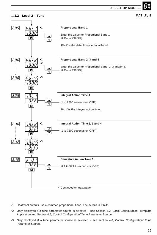
Proportional Band 1
Enter the value for Proportional Band 1.[0.1% to 999.9%]
'Pb-1' is the default proportional band.
Proportional Band 2, 3 and 4
Enter the value for Proportional Band 2, 3 and/or 4.[0.1% to 999.9%]
Integral Action Time 1
[1 to 7200 seconds or 'OFF']
'IAt.1' is the integral action time.
Integral Action Time 2, 3 and 4
[1 to 7200 seconds or 'OFF']
Derivative Action Time 1
[0.1 to 999.9 seconds or 'OFF']
Continued on next page.
•1 Heat/cool outputs use a common proportional band. The default is 'Pb-1'.
•2 Only displayed if a tune parameter source is selected – see Section 4.2, Basic Configuration/ TemplateApplication and Section 4.6, Control Configuration/ Tune Parameter Source.
•3 Only displayed if a tune parameter source is selected – see section 4.6, Control Configuration/ TuneParameter Source.
OFFIAt.42..12
OFFIAt..22.10
OFFIAt.12.09
•2
•3
•1
100.0Pb-22.06
100.0Pb-12.05
Pb-42.08
100.0
•3
OFFdrV12.13
•1
•2

30
8
50.0rSt.1
2.15
1.0 Ab.1
2.17
•1
•2
OFFCbnd2..21
Deadband
Set Point
Process Variable
Control Output
…3 SET UP MODE
Approach Band 1
[0.1 to 3.0 proportional bands]
This parameter limits when derivative action time 1 is applied. When theprocess variable is outside the approach band, derivative action is not applied.
Manual Reset Value 1The value applied to bring the master control output to the zero error pointunder normal load conditions (integral action disabled) or the offsetapplied to the control output (integral action enabled).
[0.0 to 100%]
Note. Manual reset is applied whether or not an integral action timeis selected.
Control DeadbandWhen the process variable is in the deadband, changes to the controloutput due to proportional and integral action are suppressed.
[In engineering units or 'OFF']
Continued on next page.
…3.2 Level 2 – Tune
•1 Not displayed if the associated derivative action time is set to OFF.
•2 If manual control is selected and no integral action time is set, the manual reset value is calculatedautomatically to give bumpless transfer into auto control.
2.15, 2.17, 2.21
31
8
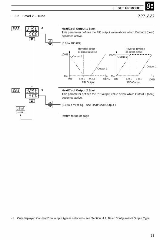
Heat/Cool Output 1 StartThis parameter defines the PID output value above which Output 1 (heat)becomes active.
[0.0 to 100.0%]
Heat/Cool Output 2 StartThis parameter defines the PID output value below which Output 2 (cool)becomes active.
[0.0 to ≤ Y1st %] – see Heat/Cool Output 1
Return to top of page
3 SET UP MODE…
2.22...2.23…3.2 Level 2 – Tune
50.0Y2.St2...23
50.0Y1.St2...22
LEV2tUNE
•1
•1
•1 Only displayed if a Heat/Cool output type is selected – see Section 4.2, Basic Configuration/ Output Type.
Output 2
PID Output
0%
100%
100%0% Y2.St Y1.St
Output 1
Output 2
PID Output
0%
100%
100%0% Y2.St Y1.St
Output 1
Reverse-director direct-reverse
Reverse-reverseor direct-direct

32
83.00...3.07
Level 3 – Set Points
Note. To select this frame from anywhere in this page, press andhold the key for a few seconds.
Local Set Point Value 1Set the default local set point value.[Within set point high and low limits, in engineering units – see Level 9]
Local Set Point Values 2 to 4
[Within set point high and low limits, in engineering units – see Level 9]
Remote Set Point RatioThe remote set point value is
(ratio x remote set point input) + bias.
[0.001 to 9.999]
Remote Set Point Bias
[In engineering units]
Continued…
SEtPLEV.33.00
1.000rAtO
0BIAS
3.06
3.07
400LSP43.04
200LSP23.02
500LSP13.01
•1
•2
•2
•1
…3 SET UP MODE
•1 Displayed only if a local set point source is selected – see Section 4.5/ Set Point Configuration/ Local/RemoteSet Point Source.
•2 Displayed only for templates with a remote set point.
3.3 Level 3 – Set Points
Note. Level 3 is not applicable if Auto/Manual Station or Indicator templates are selected.
33
8
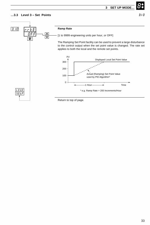
Ramp Rate
[1 to 9999 engineering units per hour, or OFF]
The Ramping Set Point facility can be used to prevent a large disturbanceto the control output when the set point value is changed. The rate setapplies to both the local and the remote set points.
Return to top of page.
…3.3 Level 3 – Set Points
3 SET UP MODE…
3.10
OFFr.rtE3.10
Actual (Ramping) Set Point Valueused by PID Algorithm*
0
100
200
300
1 Hour
Displayed Local Set Point Value
Time
PV
* e.g. Ramp Rate = 200 Increments/HourLEV3SEt.P
34
84.00...4.08
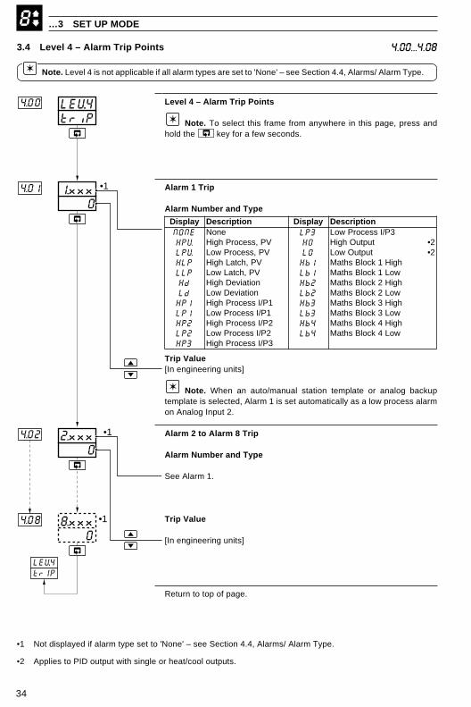
Level 4 – Alarm Trip Points
Note. To select this frame from anywhere in this page, press andhold the key for a few seconds.
Alarm 1 Trip
Alarm Number and Type
Trip Value[In engineering units]
Note. When an auto/manual station template or analog backuptemplate is selected, Alarm 1 is set automatically as a low process alarmon Analog Input 2.
Alarm 2 to Alarm 8 Trip
Alarm Number and Type
See Alarm 1.
Trip Value
[In engineering units]
Return to top of page.
triPLEV.44.00
4.08
02.xxx4.02
01.xxx4.01
08.xxx •1
•1
•1
LEV.4trIP
…3 SET UP MODE
•1 Not displayed if alarm type set to 'None' – see Section 4.4, Alarms/ Alarm Type.
•2 Applies to PID output with single or heat/cool outputs.
3.4 Level 4 – Alarm Trip Points
Note. Level 4 is not applicable if all alarm types are set to 'None' – see Section 4.4, Alarms/ Alarm Type.
yalpsiD noitpircseD yalpsiD noitpircseDENON enoN 3PL 3P/IssecorPwoLVPH VP,ssecorPhgiH OH tuptuOhgiH 2•VPL VP,ssecorPwoL OL tuptuOwoL 2•PLH VP,hctaLhgiH 1bH hgiH1kcolBshtaMPLL VP,hctaLwoL 1bL woL1kcolBshtaMdH noitaiveDhgiH 2bH hgiH2kcolBshtaMdL noitaiveDwoL 2bL woL2kcolBshtaM1PH 1P/IssecorPhgiH 3bH hgiH3kcolBshtaM1PL 1P/IssecorPwoL 3bL woL3kcolBshtaM2PH 2P/IssecorPhgiH 4bH hgiH4kcolBshtaM2PL 2P/IssecorPwoL 4bL woL4kcolBshtaM3PH 3P/IssecorPhgiH
35
85.00...5.04
3 SET UP MODE…
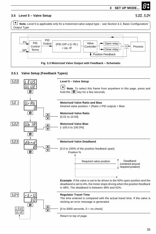
Level 5 – Valve Setup
Note. To select this frame from anywhere in this page, press andhold the key for a few seconds.
Motorized Valve Ratio and BiasDesired valve position = (Ratio x PID output) + Bias
Motorized Valve Ratio[0.01 to 10.00]
Motorized Valve Bias[–100.0 to 100.0%]
Motorized Valve Deadband
[0.0 to 100% of the position feedback span]
Example. If the valve is set to be driven to the 50% open position and thedeadband is set to 4%, the motor stops driving when the position feedbackis 48%. The deadband is between 48% and 52%.
Regulator Travel TimeThe time entered is compared with the actual travel time. If the valve issticking an error message is generated.
[0 to 5000 seconds, 0 = no check]
Return to top of page.
U.LU.ELEV.55.00
1..0d.bnd5.03
0VbIA5.02
0VrAt5..01
30r.trU.5.04
Position %
Required valve position Deadband(centered aroundrequired position)
LEV.5VLVE
PIDControlTerms
PV
SPtProcess
Open relayValveController
Position Feedback
Close relay
PIDOutput (PID O/P x V.rAt)
+ V.bIA
Fig. 3.3 Motorized Valve Output with Feedback – Schematic
3.5.1 Valve Setup (Feedback Types)
3.5 Level 5 – Valve Setup
Note. Level 5 is applicable only for a motorized valve output type – see Section 4.2, Basic Configuration/Output Type.

36
83.5.2 Valve Setup (Boundless Types) – Fig. 3.4A ‘boundless’ process controller provides an output that is effectively the time derivative of the required regulatorposition, i.e. the COMMANDER 500 signals the regulator, not where to go to (position derivative), but in whichdirection to travel and how far to move, by a series of integral action pulses. Thus, the COMMANDER 500 doesnot need to know the absolute regulator position and is unaffected when regulator reaches the upper or lower limit,as determined by the regulator’s limit switches (giving rise to the term ‘boundless’).
When a deviation from set point is introduced the regulator is driven, for a length of time equivalent to theproportional step. The regulator is then driven by integral action pulses until the deviation is within the deadbandsetting.
…3 SET UP MODE
ProportionalStep
TimeControlDeviation
Raise
Lower
Time
IntegralAction Pulses
ProportionalStep Proportional
StepIntegral
Action Pulses
+
–
Fig. 3.4 Boundless Control Action
Calculation for Control Pulses (Boundless Control)The following calculations are shown for guidance when setting deadband, proportional and integral values. Theycan be used to check the suitability of boundless control for a particular actuator/application.
Minimum 'ON' time of integral action pulses (for a fixed control deviation).
= Travel Time x Deadband %
% Proportional Band (in seconds)
Minimum (approximate) time between integral action pulses (for a fixed control deviation)
= Integral Action Time x Deadband %
2 x % Control Deviation (in seconds)
Duration of the proportional step
= 2 x % Control Deviation% Proportional Band x Travel Time in Seconds
% Control Deviation
= Set Point – Process Variable
Eng Hi – Eng Lox 100%
% Deadband
= Deadband (eng units)
Eng Hi – Eng Lox 100%

37
85.00...5.04…3.5.2 Valve Setup – Boundless
Level 5 – Valve Setup
Note. To select this frame from anywhere in this page, press andhold the key for a few seconds.
Boundless Deadband
[In engineering units]
Regulator Travel TimeThe time taken for the regulator to travel from the fully open to the fullyclosed position.
[1 to 5000 seconds]
Return to top of page.
U.LU.ELEV.55.00
0r.trU.
5.03
5..04
0d.bnd
Position %
Control Set Point Deadband(centered around
Set Point)
LEV.5VLVE
3 SET UP MODE

38
4 CONFIGURATION MODE
4.1 IntroductionTo access the Configuration mode (Levels 6 to E) the correct password must be entered in the security codeframe.
LEV6 Basic ConfigurationTemplate applicationOutput typeControl actionMains rejection frequency
LEV7 Analog Inputs 1 to 3TypeElectrical rangeDecimal placesEngineering rangeBroken sensor driveInput filter time constant
LEV9 Set PointsTracking enableSet point limitsLocal set point sources 1 to 4Local/remote set point selection
LEV8 Alarms 1 to 8TypeTrip levelHysteresis band
LEVA Control ConfigurationPower fail recovery actionOutput high/low limitsSlew rate + disableConfigured outputs 1 to 3Manual output selection sourcesAuto mode selection sourceTune parameter sources 1 to 4
LEVb Operator ConfigurationAuto/manual key enablesLocal/remote key enablesAlarm acknowledge key enableOperator set point adjust enableOperator ratio/bias enablePassword settingsClock settings
LEVC Output AssignmentOutputs 1 and 2 typeDigital output
Assignment sourcePolarity
Analog outputAssignment sourceElectrical rangeEngineering range
Relay outputs 1 to 4Assignment sourcePolarity
LEVd Serial Communications2-/4-wire connection2400/9600/19200 baud rateParityMODBUS address
LEVE CalibrationOffset/span adjustmentMotorized valve feedback
APPL
INPt
SEt.P
ALr
CNtL
OPEr
ASSN
SErL
CAL
Valid Set Up orConfigurationpassword
ValidConfigurationpassword
Pressand hold
LEV1OPEr
LEV2tUNE
LEV5VLVE
LEV6APPL
450.2500.0
7050
COdEOFF
AtNE
Pressand hold
LEVECAL
Valid Auto-tune,Set Up orConfigurationpassword
Invalidpassword
Autotunepassword
Enter the Auto-tune,Set Up orConfigurationpassword
Set Uppassword
Note. When in the configuration mode,alternate bargraph led's are illuminated. Allrelays and digital outputs are de-energized andall analog outputs revert to the set minimumcurrent output.
Fig. 4.1 Configuration Mode – Summary
39
4.2 Level 6 – Basic Configuration 6.00...6.01
4 CONFIGURATION MODE…
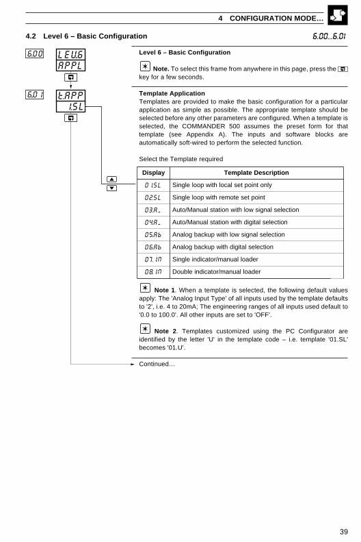
Level 6 – Basic Configuration
Note. To select this frame from anywhere in this page, press the key for a few seconds.
Template ApplicationTemplates are provided to make the basic configuration for a particularapplication as simple as possible. The appropriate template should beselected before any other parameters are configured. When a template isselected, the COMMANDER 500 assumes the preset form for thattemplate (see Appendix A). The inputs and software blocks areautomatically soft-wired to perform the selected function.
Select the Template required
Note 1. When a template is selected, the following default valuesapply: The 'Analog Input Type' of all inputs used by the template defaultsto '2', i.e. 4 to 20mA; The engineering ranges of all inputs used default to'0.0 to 100.0'. All other inputs are set to 'OFF'.
Note 2. Templates customized using the PC Configurator areidentified by the letter 'U' in the template code – i.e. template '01.SL'becomes '01.U'.
Continued…
APPLLEV.66.00
1.SLt.APP6..01
yalpsiD noitpircseDetalpmeT
LS.10 ylnotniopteslacolhtiwpoolelgniS
LS.20 tnioptesetomerhtiwpoolelgniS
MA.30 noitceleslangiswolhtiwnoitatslaunaM/otuA
MA.40 noitceleslatigidhtiwnoitatslaunaM/otuA
bA.50 noitceleslangiswolhtiwpukcabgolanA
bA.60 noitceleslatigidhtiwpukcabgolanA
NI.70 redaollaunam/rotacidnielgniS
NI.80 redaollaunam/rotacidnielbuoD

40
ANLGO.tYP6.02 •1
…4.2 Level 6 – Basic Configuration
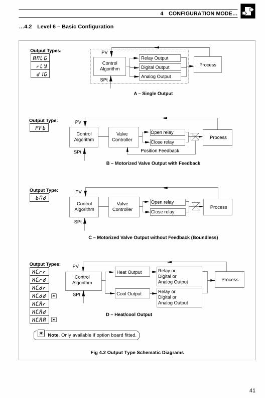
Control Output TypeThe appropriate relays, digital outputs and analog outputs are assigned tothe control output variables. The other hardware outputs are provisionallyassigned to alarm and retransmission functions but these may bechanged in the output assignment level – see Section 4.8.
Select the Output Type required – see also Fig. 4.2 overleaf and RearFold-out/ Table B.
Continued…
6.02
…4 CONFIGURATION MODE
•1 Only output types 'NONE' and 'ANLG' are applicable to indicator templates. Only output type 'ANLG' isapplicable to auto/manual station and analog backup templates.
•2 Only available with option board fitted.
•3 Analog Input 3 Type defaults to '11' – Resistance Feedback.
yalpsiD epyTtuptuO
ENON enoN
GLNA )1oa=tuptuolortnoC(tuptuogolanA
YLr )1YLR=tuptuolortnoC(tuptuoyaleR
GId )1od=tuptuolortnoC(tuptuolatigiD
bFPkcabdeefhtiwevlavdezirotoM)2YLR=esolC,1YLR=nepO(
2•3•
dNbkcabdeeftuohtiwevlavdezirotoM
)2YLR=esolC,1YLR=nepO(
rr.CH yaler=2PO,yaler=1POhtiwlooc/taeH
dr.CH tuptuolatigid=2PO,yaler=1POhtiwlooc/taeH
rd.CH yaler=2PO,tuptuolatigid=1POhtiwlooc/taeH
dd.CH tuptuolatigid=2PO,tuptuolatigid=1POhtiwlooc/taeH 2•
rA.CH yaler=2PO,golana=1POhtiwlooc/taeH
dA.CH latigid=2PO,golana=1POhtiwlooc/taeH 2•
AA.CH golana=2PO,golana=1POhtiwlooc/taeH 2•
41
…4.2 Level 6 – Basic Configuration
4 CONFIGURATION MODE…
A – Single Output
ControlAlgorithm
PV
SPt
ProcessRelay Output
Digital Output
Analog Output
ANLG
rLY
dIG
Output Types:
ProcessOpen relay
Close relay
ValveController
Position Feedback
ControlAlgorithm
PV
SPt
B – Motorized Valve Output with Feedback
PFb
Output Type:
C – Motorized Valve Output without Feedback (Boundless)
ProcessOpen relay
Close relay
ValveController
ControlAlgorithm
PV
SPt
bNd
Output Type:
HC.rr
HC.rd
HC.dr
HC.dd
HC.Ar
HC.Ad
HC.AA
Output Types:
D – Heat/cool Output
PVRelay orDigital orAnalog Output Process
Heat Output
Cool Output Relay orDigital orAnalog Output
ControlAlgorithm
SPt
Note. Only available if option board fitted.
Fig 4.2 Output Type Schematic Diagrams
42
6.03...6.06…4.2 Level 6 – Basic Configuration
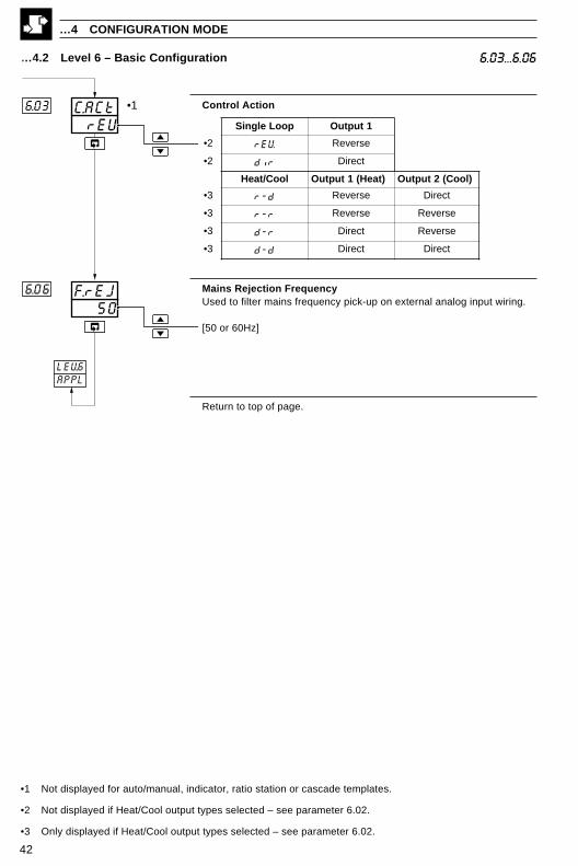
Control Action
Mains Rejection FrequencyUsed to filter mains frequency pick-up on external analog input wiring.
[50 or 60Hz]
Return to top of page.
•1 Not displayed for auto/manual, indicator, ratio station or cascade templates.
•2 Not displayed if Heat/Cool output types selected – see parameter 6.02.
•3 Only displayed if Heat/Cool output types selected – see parameter 6.02.
50F.rEJ6.06
rEUC.ACt6.03 •1
LEV.6APPL
…4 CONFIGURATION MODE
pooLelgniS 1tuptuO
2• VEr esreveR
2• rid tceriD
looC/taeH )taeH(1tuptuO )looC(2tuptuO
3• d-r esreveR tceriD
3• r-r esreveR esreveR
3• r-d tceriD esreveR
3• d-d tceriD tceriD

43
7.00...7.034.3 Level 7 – Analog Inputs
Level 7 – Analog Inputs
Note 1. Refer also to the rear fold-out, Table A – Template Applications.
Note 2. To select this frame from anywhere in this page, press the key for a few seconds.
Analog Input 1 (I/P1) Type & Electrical Range
Temperature Units (I/P1)
C – THC readings displayed in °CF – THC readings displayed in °F
Decimal Places (Engineering Range, I/P1)
0 XXXX1 XXX.X2 XX.XX3 X.XXX
Continued…
4 CONFIGURATION MODE…
InPtLEV.77.00
0dP.17.03
CUNt.17.02
2tYP.17.01
•1
•1 Only displayed if THC or RTD input types are selected
yalpsiD noitpircseD yalpsiD noitpircseD
FFO desUtoN P DTR001TP
b BepyTCHT 1 Am02ot0
E EepyTCHT 2 Am02ot4
J JepyTCHT 3 V5ot0
K KepyTCHT 4 V5ot1
L LepyTCHT 6 Vm05ot0
N NepyTCHT 7 reziraeniltoorerauqsAm02ot4
r RepyTCHT 8 2/3rewopAm02ot4
S SepyTCHT 9 2/5rewopAm02ot4
t TepyTCHT U motsuC

44
7.04...7.07… 4.3 Level 7 – Analog Inputs
Engineering High (I/P1)
[–999 to 9999]
Note. This parameter defaults to the maximum allowed value whenTHC or RTD inputs are selected – see Table 4.1.
Table 4.1 Engineering Limits, THC & RTD Inputs
Engineering Low (I/P1)
[–999 to 9999]
Note. This parameter defaults to the minimum allowed value whenTHC or RTD inputs are selected – see Table 4.1.
Broken Sensor Drive (I/P1)
NONE – No action. Actual input values remain valid.UP – Input driven to the maximum upscale value (999)dN – Input driven to the minimum downscale value (–999)
In the event of a fault being detected on the input, the input is driven in thedirection selected.
Input Filter Time Constant (I/P1)The input values are averaged over the time set.
[0 to 60 seconds]
Continued…
…4 CONFIGURATION MODE
0FLt.17.07
1000En1.H7.04
0EnI.L
UPb.Sd1
7.05
7.06
THC/RTD Type °C °F
Min. Max. Min. Span Min. Max. Min. Span
Type B –18 1800 710 0 3272 1278
Type E –100 900 45 –148 1652 81
Type J –100 900 50 –148 1652 90
Type K –100 1300 65 –148 2372 117
Type L –100 900 50 –148 1652 90
Type N –200 1300 90 –328 2372 162
Type R & S –18 1700 320 0 3092 576
Type T –250 300 60 –418 572 108
Pt100 –200 600 25 –328 1112 45

45
7.08...7.14… 4.3 Level 7 – Analog Inputs
1000En2.H7..11
0dP.27..10
CUNt27.09
2tYP27.08
0En2.L7.12
•1
•2
UPbsd.27.13
0FLt.27.14
Analog Input Type & Electrical Range (I/P2)
Note. THC inputs can only be used on I/P2 if I/P1 is also set to THC.
Temperature Units (I/P2)
C – THC readings displayed in °CF – THC readings displayed in °F
Decimal Places (Engineering Range, I/P2)
0 XXXX1 XXX.X2 XX.XX3 X.XXX
Engineering High (I/P2)
[–999 to 9999]
Note. This parameter defaults to the maximum allowed value whenTHC input type is selected – see Table 4.1.
Engineering Low (I/P2)
[–999 to 9999]
Note. This parameter defaults to the minimum allowed value whenTHC input is selected – see Table 4.1.
Broken Sensor Drive (I/P2)
NONE – No action. Actual input values remain valid.UP – Input driven to the maximum upscale value (999)dN – Input driven to the minimum downscale value (–999)
Filter Time Constant (I/P2)The input values are averaged over the time set.
[0 to 60 seconds]
Continued…
4 CONFIGURATION MODE…
•1 Frames 7.09 to 7.14 are not displayed if Analog Input Type 2 is set to 'OFF'.
•2 Only displayed if THC input type is selected.
yalpsiD noitpircseD yalpsiD noitpircseDFFO desUtoN t 1epyTCHT
b BepyTCHT 1 Am02ot0E EepyTCHT 2 Am02ot4J JepyTCHT 6 Vm05ot0K KepyTCHT 7 reziraeniltoorerauqsAm02ot4L LepyTCHT 8 2/3rewopAm02ot4N NepyTCHT 9 2/5rewopAm02ot4r RepyTCHT U motsuCS SepyTCHT

46
… 4.3 Level 7 – Analog Inputs 7.15...7.21
Analog Input Type & Electrical Range (I/P3)
Temperature Units
C – THC readings displayed in °CF – THC readings displayed in °F
Decimal Places
0 XXXX1 XXX.X2 XX.XX3 X.XXX
Engineering High
[–999 to 9999]
Note. This parameter defaults to the maximum allowed value whenTHC or RTD inputs are selected – see Table 4.1.
Engineering Low
[–999 to 9999]
Note. This parameter defaults to the minimum allowed value whenTHC or RTD inputs are selected – see Table 4.1.
Broken Sensor Drive (I/P3)
NONE – No action. Actual input values remain valid.UP – Input driven to the maximum upscale value (999)dN – Input driven to the minimum downscale value (–999)
Filter Time Constant (I/P3)The input values are averaged over the time set.
[0 to 60 seconds]
Return to top of page.
…4 CONFIGURATION MODE
•1 Frames 7.16 to 7.21 are not displayed if Analog Input Type 3 is set to 'OFF'.
•2 Only displayed if THC or RTD input types are selected.
1000En3.H7...18
0dP.37...17
CUNt37..16
2tYP.37.15
0En3.L
7...19
•1
•2
UPbSd.37.20
0FLt.37.21
LEV7INPt
yalpsiD noitpircseD yalpsiD noitpircseDFFO desUtoN 1 Am02ot0
b BepyTCHT 2 Am02ot4E EepyTCHT 3 V5ot0J JepyTCHT 4 V5ot1K KepyTCHT 6 Vm05ot0L LepyTCHT 7 reziraeniltoorerauqsAm02ot4N NepyTCHT 8 2/3rewopAm02ot4r RepyTCHT 9 2/5rewopAm02ot4S SepyTCHT 11 rofkcabdeefecnatsiseRt TepyTCHT evlavdezirotomP DTR001TP U motsuC

47
4 CONFIGURATION MODE…
4.4 Level 8 – Alarms
Note. Any type of alarm can be used to sound an annunciator (klaxon/horn) which is disabled when thealarm is acknowledged. This is achieved by assigning the relay to the acknowledge state of the alarm insteadof the actual alarm state.
Fig 4.4 High and Low Deviation Alarm Action
Fig 4.3 Using an Alarm to Sound a Horn
Trip point
Operatoracknowledges
alarm
Alarm State (A.x)
Acknowledge State (ACK.x)
ProcessVariable
On
Off
On
OffrLY.xACK.x
RLY.x
Horn
Relay assigmentframe in Level C,Output Assignment.
Alarm On
Alarm OffNegativeTrip Value
Positive Trip Value
Low Deviation Alarm
Control Set Point
Hysteresis Low Deviation+ve Trip Value
Alarm On
Alarm Off
HysteresisLow Deviation–ve Trip Value
ProcessVariable
High Deviation+ve Trip ValueHysteresis
Alarm On
Alarm Off
Control Set Point
Alarm On
Alarm Off
PositiveTrip Value Negative
Trip Value
High Deviation–ve Trip Value
High Deviation Alarm
Hysteresis
Process Variable
48
…4 CONFIGURATION MODE
…4.4 Level 8 – Alarms
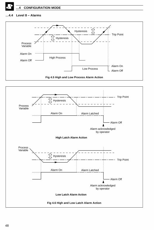
Fig 4.5 High and Low Process Alarm Action
Fig 4.6 High and Low Latch Alarm Action
Trip Point
Alarm On
Alarm Off
Alarm Latched
Alarm acknowledgedby operator
Hysteresis
ProcessVariable
Trip Point
Alarm On
Alarm Off
Alarm Latched
Alarm acknowledgedby operator
Hysteresis
ProcessVariable
High Latch Alarm Action
Low Latch Alarm Action
Trip Point
Alarm On
Alarm Off
Alarm On
Alarm Off
High Process
Low Process
Hysteresis
Hysteresis
ProcessVariable

49
ALMSLEV.88.00
HP1tYP.18.01
0HYS.18.03
0trP.18.02
…4.4 Level 8 – Alarms
Level 8 – Alarms
Note. To select this frame from anywhere in this page, press the key for a few seconds.
Alarm 1 TypeSee Figs 4.3 to 4.6
Note. Alarm 1 is set automatically as a Low Process alarm on I/P2when template 3 or 5 is selected.
Alarm 1 Trip
Alarm Number
Trip Value
[In engineering units]
Alarm 1 HysteresisSet the hysteresis value (in engineering units) for Alarm 1.
The alarm is activated at the trip level but is only deactivated when theprocess variable has moved into the safe region by an amount equal to thehysteresis value – see Figs. 4.4 to 4.6.
[In engineering units]
Note. Time hysteresis is set using the PC Configurator.
Continued…
8.00...8.03
4 CONFIGURATION MODE…
•1 Applies to the PID output with single or heat/cool output types selected – see Section 3.4.
yalpsiD noitpircseD yalpsiD noitpircseDENON enoN 3PL 3P/IssecorPwoLVPH VP,ssecorPhgiH OH tuptuOhgiH 1•VPL VP,ssecorPwoL OL tuptuOwoL 1•PLH VP,hctaLhgiH 1bH hgiH1kcolBshtaMPLL VP,hctaLwoL 1bL woL1kcolBshtaMdH noitaiveDhgiH 2bH hgiH2kcolBshtaMdL noitaiveDwoL 2bL woL2kcolBshtaM1PH 1P/IssecorPhgiH 3bH hgiH3kcolBshtaM1PL 1P/IssecorPwoL 3bL woL3kcolBshtaM2PH 2P/IssecorPhgiH 4bH hgiH4kcolBshtaM2PL 2P/IssecorPwoL 4bL woL4kcolBshtaM3PH 3P/IssecorPhgiH
50
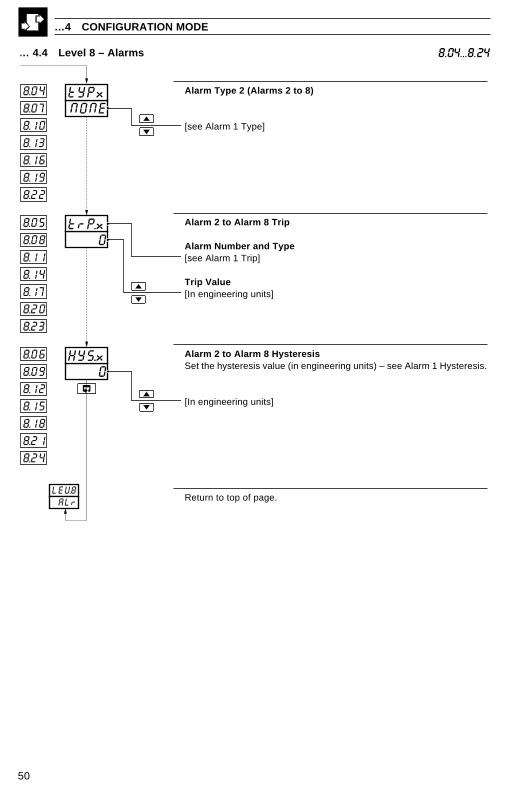
Alarm Type 2 (Alarms 2 to 8)
[see Alarm 1 Type]
Alarm 2 to Alarm 8 Trip
Alarm Number and Type[see Alarm 1 Trip]
Trip Value[In engineering units]
Alarm 2 to Alarm 8 HysteresisSet the hysteresis value (in engineering units) – see Alarm 1 Hysteresis.
[In engineering units]
Return to top of page.
… 4.4 Level 8 – Alarms
…4 CONFIGURATION MODE
8.04...8.24
0trP.x8.05
8.06
8.07 NONEtYPx8.04
8.10
8.13
8.16
8.19
8.22
8.08
8.11
8.14
8.17
8.20
8.23
0HYS.x
8.09
8.12
8.15
8.18
8.21
8.24
LEV8 ALr
51
SEt.PLEV99.00
0SPt.L9.03
1000SPt.H9.02
OFFtrCK9.01
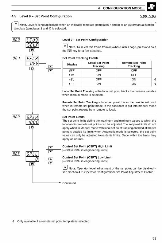
4.5 Level 9 – Set Point Configuration
Note. Level 9 is not applicable when an Indicator template (templates 7 and 8) or an Auto/Manual stationtemplate (templates 3 and 4) is selected.
9.00...9.03
4 CONFIGURATION MODE…
Level 9 – Set Point Configuration
Note. To select this frame from anywhere in this page, press and holdthe key for a few seconds.
Set Point Tracking Enable
Local Set Point Tracking – the local set point tracks the process variablewhen manual mode is selected.
Remote Set Point Tracking – local set point tracks the remote set pointwhen in remote set point mode. If the controller is put into manual modethe set point reverts from remote to local.
Set Point LimitsThe set point limits define the maximum and minimum values to which thelocal and/or remote set points can be adjusted.The set point limits do notapply when in Manual mode with local set point tracking enabled. If the setpoint is outside its limits when Automatic mode is selected, the set pointvalue can only be adjusted towards its limits. Once within the limits theyapply as normal.
Control Set Point (CSPT) High Limit[–999 to 9999 in engineering units]
Control Set Point (CSPT) Low Limit[–999 to 9999 in engineering units]
Note. Operator level adjustment of the set point can be disabled –see Section 4.7, Operator Configuration/ Set Point Adjustment Enable.
Continued…
•1 Only available if a remote set point template is selected.
yalpsiDtnioPteSlacoL
gnikcarTtnioPteSetomeR
gnikcarT
FFO FFO FFO
COL NO FFO
MEr FFO NO 1•
r-L NO NO 1•
52
…4.5 Level 9 – Set Point Configuration 9.06...9.11
…4 CONFIGURATION MODE
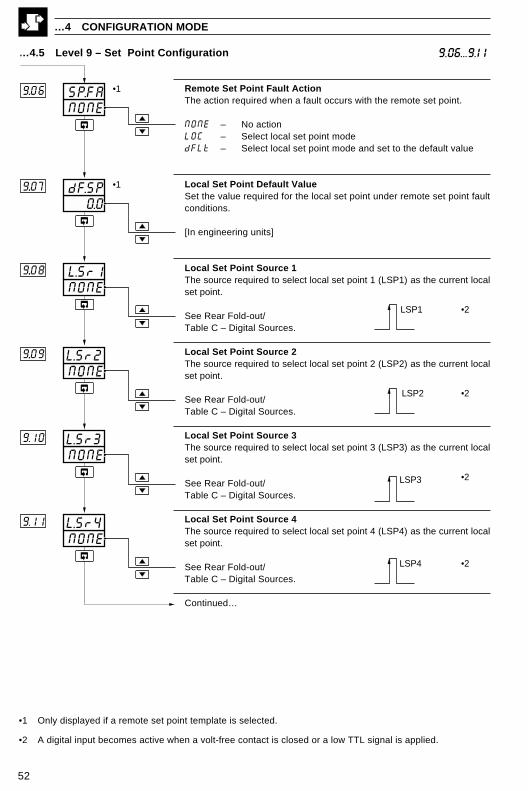
Remote Set Point Fault ActionThe action required when a fault occurs with the remote set point.
NONE – No actionLOC – Select local set point modedFLt – Select local set point mode and set to the default value
Local Set Point Default ValueSet the value required for the local set point under remote set point faultconditions.
[In engineering units]
Local Set Point Source 1The source required to select local set point 1 (LSP1) as the current localset point.
See Rear Fold-out/Table C – Digital Sources.
Local Set Point Source 2The source required to select local set point 2 (LSP2) as the current localset point.
See Rear Fold-out/Table C – Digital Sources.
Local Set Point Source 3The source required to select local set point 3 (LSP3) as the current localset point.
See Rear Fold-out/Table C – Digital Sources.
Local Set Point Source 4The source required to select local set point 4 (LSP4) as the current localset point.
See Rear Fold-out/Table C – Digital Sources.
Continued…
NONEL.Sr29..09
NONEL.Sr19..08
NONEL.Sr3
NONEL.Sr4
9.10
9.11
NONESP.FA9..06
0.0dF.SP9..07
LSP1
LSP2
LSP3
LSP4
•2
•2
•2
•2
•1
•1
•1 Only displayed if a remote set point template is selected.
•2 A digital input becomes active when a volt-free contact is closed or a low TTL signal is applied.

53
…4.5 Level 9 – Set Point Configuration 9.12...9.14
4 CONFIGURATION MODE…
Local/Remote Set Point Selection SourceThe source required to lock into remote set point mode.When the source is active the L LR key does not operate.
See Rear Fold-out/Table C – Digital Sources.
Local Set Point Selection SourceThe source required to select local set point mode.
See Rear Fold-out/Table C – Digital Sources.
Remote Set Point Selection SourceThe source required to select remote set point mode.
See Rear Fold-out/Table C – Digital Sources.
Return to top of page.
NONELr.5r9.12
NONEr.SrC9.14
NONELC.5r9.13
Local
Remote
Local
Local Set Point Mode
Remote Set Point Mode
•1
•1
•1
•1
•1
•1
SEt.PLEV9
•1 Digital inputs are active when a volt-free contact is closed or a low TTL signal is applied

54
4.6 Level A – Control Configuration
Note. Level A is not displayed if an indicator template is selected.
…4 CONFIGURATION MODE
Level A – Control Configuration
Note. To select this frame from anywhere in this page, press and holdthe key for a few seconds.
Power Fail Recovery ModeSelect the default power failure mode required following a powerinterruption or failure.
Recovery TimeIf power is restored within the recovery time, the controller continues in thelast mode when power fail recovery modes 7 or 8 are selected.
[0 to 9999 seconds]
Continued…
CntLLEVAA.00
0rEC.tA.02
0P.rECA.01
•1
A.00...A.02
yalpsiD gnitteS yalpsiD gnitteS
0 edomtsaL 5,edomotuA
tesermretlargetni
1,edomlaunaM
tuptuotsalgnisu 6,edomotuA
mretlargetnitsalgnisu
2htiwedomlaunaM
tuptuo%0.0 7
egatuorewoP ≤otuA:emityrevoceR
>egatuorewoP.edomlaunaM:emityrevoceR
tuptuotsal,edom
3htiwedomlaunaM
tuptuo%0.001 8
egatuorewoP ≤otuA:emityrevoceR
>egatuorewoP.edomlaunaM:emityrevoceRtuptuoderugifnoc,edom
4htiwedomlaunaMtuptuoderugifnoc
•1 Not displayed if power fail recovery modes 0 to 6 are selected.
55
4 CONFIGURATION MODE…
A.03...A.08
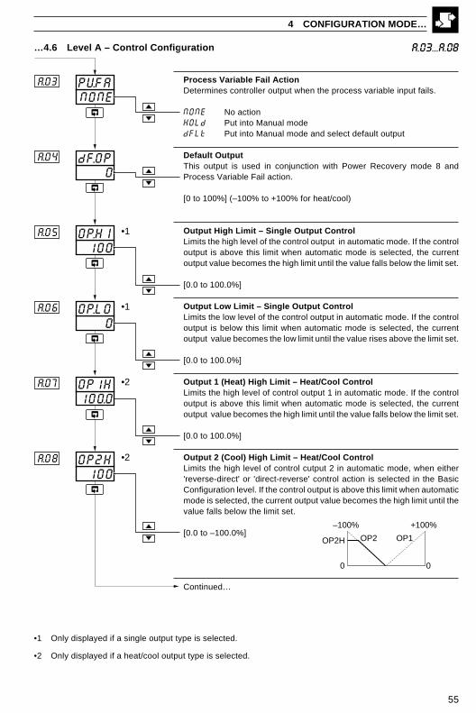
Process Variable Fail ActionDetermines controller output when the process variable input fails.
NONE No actionHOLd Put into Manual modedFLt Put into Manual mode and select default output
Default OutputThis output is used in conjunction with Power Recovery mode 8 andProcess Variable Fail action.
[0 to 100%] (–100% to +100% for heat/cool)
Output High Limit – Single Output ControlLimits the high level of the control output in automatic mode. If the controloutput is above this limit when automatic mode is selected, the currentoutput value becomes the high limit until the value falls below the limit set.
[0.0 to 100.0%]
Output Low Limit – Single Output ControlLimits the low level of the control output in automatic mode. If the controloutput is below this limit when automatic mode is selected, the currentoutput value becomes the low limit until the value rises above the limit set.
[0.0 to 100.0%]
Output 1 (Heat) High Limit – Heat/Cool ControlLimits the high level of control output 1 in automatic mode. If the controloutput is above this limit when automatic mode is selected, the currentoutput value becomes the high limit until the value falls below the limit set.
[0.0 to 100.0%]
Output 2 (Cool) High Limit – Heat/Cool ControlLimits the high level of control cutput 2 in automatic mode, when either'reverse-direct' or 'direct-reverse' control action is selected in the BasicConfiguration level. If the control output is above this limit when automaticmode is selected, the current output value becomes the high limit until thevalue falls below the limit set.
[0.0 to –100.0%]
Continued…
…4.6 Level A – Control Configuration
•1 Only displayed if a single output type is selected.
•2 Only displayed if a heat/cool output type is selected.
100OP.HIA.05
0dF.OPA.04
NONEPVFAA.03
•1
0OP.L0A.06 •1
100.0OP1HA.07 •2
100OP2HA.08 •2
OP1OP2OP2H
–100% +100%
0 0

56
0FFSrd5A..11
0FFM5r1A.12
Slew rate disabled
OFFOP.SrA.10
0OP2LA.09 •1
OP1OP2
OP2L
time
EnabledEnabled
Auto
Manual withoutput = C.OP1 •2
+100%+100%
00
…4.6 Level A – Control Configuration
Output 2 (Cool) Low Limit – Heat/Cool ControlLimits the low level of control output 2 in automatic mode, when 'reverse-reverse' or 'direct-direct' control action is selected in the BasicConfiguration level. If the control output is below this limit when automaticmode is selected, the current output value becomes the low limit until thevalue rises above the limit set.
[0 to 100%]
Output Slew RateThe maximum rate of change of the control output (or both control outputsfor heat/cool).
[0.01 to 99.99% change persecond or 'OFF']
Note. The default slew rate setting is applied to both increasing anddecreasing output values. The slew rate setting can be applied to eitherincreasing values only or decreasing values only using the PCConfigurator.
Slew Rate Disable SourceThe digital source required to disable slew rate control of the output.
See Rear Fold-out/ Table C –Digital Sources.
Manual 1 Mode Selection SourceThe digital source required to select manual mode and ConfiguredOutput 1.
See Rear Fold-out/ Table C –Digital Sources.
Continued…
…4 CONFIGURATION MODE
A.09...A.12
•1 Only displayed if reverse-reverse or direct-direct control actions are selected.
•2 Digital inputs are active when a volt free contact is closed or a low TTL signal is applied.

57
4 CONFIGURATION MODE…
…4.6 Level A – Control Configuration
Configured Output 1The control output value required when manual is selected by manualmode source 1.
[0 to 100% or LAST (non-heat/cool)][–100 to 100% (heat/cool only)]
Manual Mode Selection Source 2The digital source required to select manual mode and ConfiguredOutput 2.
See Rear Fold-out/ Table C –Digital Sources.
Configured Output 2The control output value required when manual is selected by manualmode source 2.
[0 to 100% or LAST (non-heat/cool)][–100 to 100% (heat/cool only)]
Auto/Manual Selection SourceUsed with auto/manual station.The source required to lock into manual mode with Configured Output 3.Switching from manual to auto is not possible via the front panel.
See Rear Fold-out/ Table C –Digital Sources.
Note. If template 3 is selected, the source is assigned to alarm 1. Iftemplate 4 is selected, the source is assigned to digital input 1.
Configured Output 3The control output value required when manual mode is selected by theauto/manual selection source.
[0 to 100% or LAST (non-heat/cool)][–100 to 100% (heat/cool only)]
Continued…
A.13...A.17
•1 Digital inputs are active when a volt free contact is closed or a low TTL signal is applied
0FFAM.5r
0.0COP.3
A.16
A.17
0.0C.OP2A..15
0FFM5r2A..14
0.0C.OP1A.13
Auto
Manual with output = C.OP2 •1
Auto
Manual with output = C.OP3 •1
Auto

58
…4.6 Level A – Control Configuration A.18...A.22
…4 CONFIGURATION MODE
Auto Mode Selection SourceSelect the digital source used to activate auto mode.
See Rear Fold-out/ Table C –Digital Sources.
Tune Parameter Source 1 (Gain Scheduling)Determine the digital source used to select the proportional 1 and integral1 terms as the tuning parameters.
See Rear Fold-out/ Table C –Digital Sources.
Tune Parameter Source 2 (Gain Scheduling)Determine the digital source used to select the proportional 2 and integral2 terms as the tuning parameters.
See Rear Fold-out/ Table C –Digital Sources.
Tune Parameter Source 3 (Gain Scheduling)Determine the digital source used to select the proportional 3 and integral3 terms as the tuning parameters..
See Rear Fold-out/ Table C –Digital Sources.
Tune Parameter Source 4 (Gain Scheduling)Determine the digital source used to select the proportional 4 and integral4 terms as the tuning parameters.
See Rear Fold-out/ Table C –Digital Sources.
Return to top of page.
0FFA.5rCA.18
0FFt4.SrA...22
0FFt3.5rA...21
0FFt2.SrA..20
0FFt1.SrA.19
•2
•2
•2
Select Pb-1 and IAt.1
•2
Manual
•1Auto
LEVACNtL
•1
Select Pb-2 and IAt.2 •1
Select Pb-3 and IAt.3 •1
Select Pb-4 and IAt4 •1
•1 Digital inputs are active when a volt free contact is closed or a low TTL signal is applied.
•2 PB–x and IAt.x values are set in Level 2 – see Section 3.2, Tune/Proportional Band x and Integral ActionTime x. This function is not available with Cascade control and it is not applicable to Auto/Manual Station, Indicatoror Ratio Station templates.

59
4.7 Level B – Operator Configuration
Level B – Operator Configuration
Note. To select this frame from anywhere in this page, press and holdthe key for a few seconds.
Front Panel Auto/Manual Key Enable
YES – EnabledNO – Disabled
Front Panel Local/Remote Key Enable
Front Panel Alarm Acknowledge Key Enable
YES – EnabledNO – Disabled
Operator Level Set Point Adjustment Enable
YES – EnabledNO – Disabled
Operator Ratio Display
YES – Ratio setting for Remote set point displayed in theoperator level.
NO – Ratio setting for Remote set point not displayedin the operator level.
Operator Bias Display
YES – Bias setting for Remote set point displayed inoperator level.
NO – Bias setting for Remote set point not displayedin operator level.
Continued…
4 CONFIGURATION MODE…
•1 Not displayed if the Indicator template in use.
•2 Only displayed if a template with remote set point is selected.
OPErLEVbb.00
NOr.d15
NOb.d15
b.05
b.06
YESS.AdJb.04
YESFPAKb.03
LrFPLrb.02
YESFP.AMb.01 •1
•1
•1
•1•2
•1•2
b.00...b.06
yalpsiD noitcAyeKetomeR/lacoLON .elbasidyeketomeR/lacoLrL .sedomtnioptesetomerdnalacolneewtebsehctiwSL2 .2ro1tniopteslacolstceleSL3 .3ro2,1tniopteslacolstceleSL4 .4ro3,2,1tniopteslacolstceleS
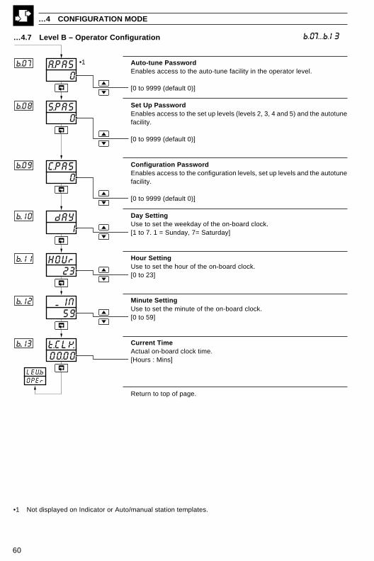
60
0A.PA5b.07
00.00t.CLKb..13
0C.PA5b.09
0S.PASb.08
1 dAYb..10
23HOUrb..11
59 MINb..12
•1
LEVbOPEr
b.07...b.13
…4 CONFIGURATION MODE
…4.7 Level B – Operator Configuration
Auto-tune PasswordEnables access to the auto-tune facility in the operator level.
[0 to 9999 (default 0)]
Set Up PasswordEnables access to the set up levels (levels 2, 3, 4 and 5) and the autotunefacility.
[0 to 9999 (default 0)]
Configuration PasswordEnables access to the configuration levels, set up levels and the autotunefacility.
[0 to 9999 (default 0)]
Day SettingUse to set the weekday of the on-board clock.[1 to 7. 1 = Sunday, 7= Saturday]
Hour SettingUse to set the hour of the on-board clock.[0 to 23]
Minute SettingUse to set the minute of the on-board clock.[0 to 59]
Current TimeActual on-board clock time.[Hours : Mins]
Return to top of page.
•1 Not displayed on Indicator or Auto/manual station templates.
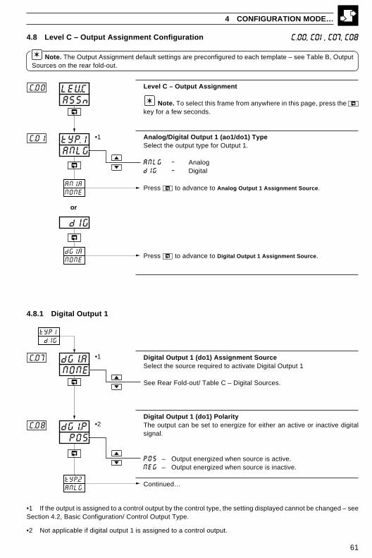
61
ASSnLEV.CC.00
ANLGtYP.1C.01
dIG
or
tYP1 dIG
NONEdGI.AC.07
POSdG1.PC.08
AN1.ANONE
dG1.ANONE
tYP.2ANLG
•1
•1
•2
4.8 Level C – Output Assignment Configuration
Note. The Output Assignment default settings are preconfigured to each template – see Table B, OutputSources on the rear fold-out.
Level C – Output Assignment
Note. To select this frame from anywhere in this page, press the key for a few seconds.
Analog/Digital Output 1 (ao1/do1) TypeSelect the output type for Output 1.
ANLG – AnalogdIG – Digital
Press to advance to Analog Output 1 Assignment Source.
Press to advance to Digital Output 1 Assignment Source.
C.00, C01, C07, C08
4 CONFIGURATION MODE…
4.8.1 Digital Output 1
Digital Output 1 (do1) Assignment SourceSelect the source required to activate Digital Output 1
See Rear Fold-out/ Table C – Digital Sources.
Digital Output 1 (do1) PolarityThe output can be set to energize for either an active or inactive digitalsignal.
POS – Output energized when source is active.NEG – Output energized when source is inactive.
Continued…
•1 If the output is assigned to a control output by the control type, the setting displayed cannot be changed – seeSection 4.2, Basic Configuration/ Control Output Type.
•2 Not applicable if digital output 1 is assigned to a control output.
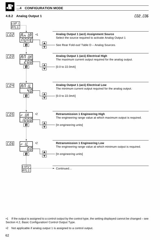
62
…4 CONFIGURATION MODE
C02...C064.8.2 Analog Output 1
Analog Output 1 (ao1) Assignment SourceSelect the source required to activate Analog Output 1
See Rear Fold-out/ Table D – Analog Sources.
Analog Output 1 (ao1) Electrical HighThe maximum current output required for the analog output.
[0.0 to 22.0mA]
Analog Output 1 (ao1) Electrical LowThe minimum current output required for the analog output.
[0.0 to 22.0mA]
Retransmission 1 Engineering HighThe engineering range value at which maximum output is required.
[In engineering units]
Retransmission 1 Engineering LowThe engineering range value at which minimum output is required.
[In engineering units]
Continued…
tYP1ANLG
NONEAnI.A
100.0r1.H
C.02
C.05
0.0r1.LC.06
20.0AN1.HC.03
4.0AN1.LC.04
tYP.2ANLG
•1
•2
•2
•1 If the output is assigned to a control output by the control type, the setting displayed cannot be changed – seeSection 4.2, Basic Configuration/ Control Output Type.
•2 Not applicable if analog output 1 is assigned to a control output.
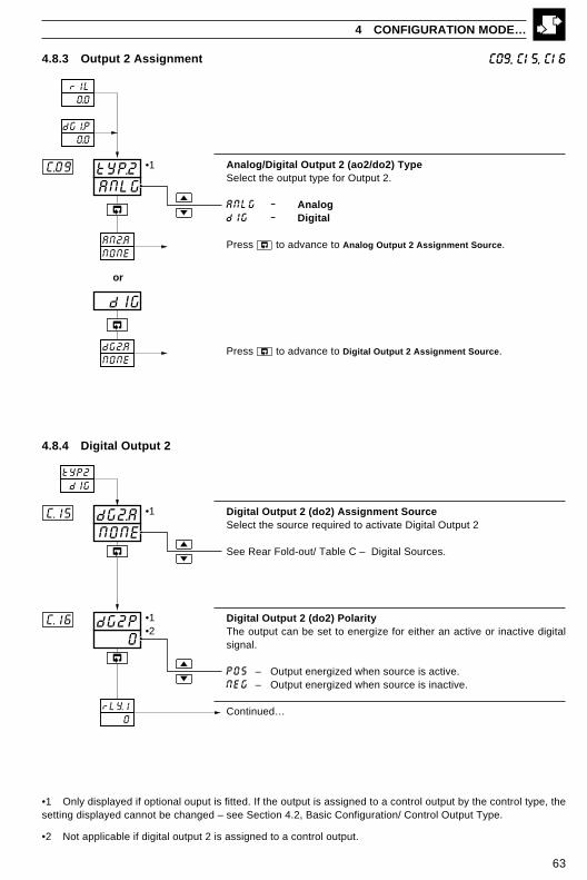
63
4.8.3 Output 2 Assignment
4 CONFIGURATION MODE…
C09, C15, C16
0dG2PC.16
NONEdG2.AC.15
ANLGtYP.2C.09
rLY.1 0
r1L 0.0
dG1.P 0.0
tYP2 dIG
dIG
or
AN2.ANONE
dG2.ANONE
•1
•1
•1
•2
Analog/Digital Output 2 (ao2/do2) TypeSelect the output type for Output 2.
ANLG – AnalogdIG – Digital
Press to advance to Analog Output 2 Assignment Source.
Press to advance to Digital Output 2 Assignment Source.
4.8.4 Digital Output 2
Digital Output 2 (do2) Assignment SourceSelect the source required to activate Digital Output 2
See Rear Fold-out/ Table C – Digital Sources.
Digital Output 2 (do2) PolarityThe output can be set to energize for either an active or inactive digitalsignal.
POS – Output energized when source is active.NEG – Output energized when source is inactive.
Continued…
•1 Only displayed if optional ouput is fitted. If the output is assigned to a control output by the control type, thesetting displayed cannot be changed – see Section 4.2, Basic Configuration/ Control Output Type.
•2 Not applicable if digital output 2 is assigned to a control output.
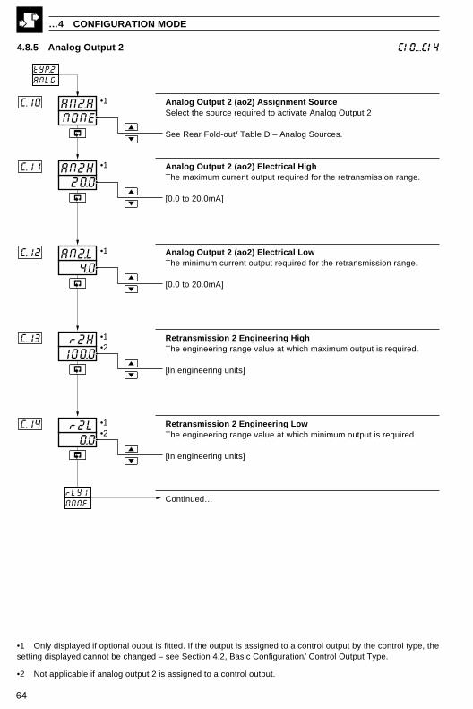
64
…4 CONFIGURATION MODE
C10...C14
Analog Output 2 (ao2) Assignment SourceSelect the source required to activate Analog Output 2
See Rear Fold-out/ Table D – Analog Sources.
Analog Output 2 (ao2) Electrical HighThe maximum current output required for the retransmission range.
[0.0 to 20.0mA]
Analog Output 2 (ao2) Electrical LowThe minimum current output required for the retransmission range.
[0.0 to 20.0mA]
Retransmission 2 Engineering HighThe engineering range value at which maximum output is required.
[In engineering units]
Retransmission 2 Engineering LowThe engineering range value at which minimum output is required.
[In engineering units]
Continued…
0.0 r2LC.14
NONEAN2.AC.10
20.0AN2HC.11
4.0AN2.LC.12
100.0 r2HC.13
rLY1NONE
tYP.2ANLG
•1
•1
•1
•1
•1
•2
•2
4.8.5 Analog Output 2
•1 Only displayed if optional ouput is fitted. If the output is assigned to a control output by the control type, thesetting displayed cannot be changed – see Section 4.2, Basic Configuration/ Control Output Type.
•2 Not applicable if analog output 2 is assigned to a control output.

65
4 CONFIGURATION MODE…
4.8.6 Relay Outputs 1 to 4 C17...C22
Relay 1 Assignment SourceSelect the source required to activate relay output 1.
See Rear Fold-out/ Table C – Digital Sources.
Relay 1 PolarityThe relay can be set to energize for either an active or inactive digitalsignal.
POS – Relay energized when source is active.NEG – Relay energized when source is inactive.
Relay 2 Assignment SourceSelect the source required to activate relay output 2
See Rear Fold-out/ Table C – Digital Sources.
Relay 2 PolarityThe relay can be set to energize for either an active or inactive digitalsignal.
POS – Relay energized when source is active.NEG – Relay energized when source is inactive.
Relay 3 Assignment SourceSelect the source required to activate relay output 3
See Rear Fold-out/ Table C – Digital Sources.
Relay 3 PolarityThe relay can be set to energize for either an active or inactive digitalsignal.
POS – Relay energized when source is active.NEG – Relay energized when source is inactive.
Continued…
POSrL2.PC.20
NONErL2.A
POSrL1.PC.18
NONErL1.AC..17
POSrL3..PC.22
NONErL3.AC.21
r2L 0.0
dG2.P 0.0
•1
•2•3
•2
•1
•1
•3
•2•3
•4
•4
C.19
•1 If the output is assigned to a control output by the control type, the setting displayed cannot be changed – seeSection 4.2, Basic Configuration/ Control Output Type.
•2 Not displayed if relay is assigned to a control output signal.
•3 Not applicable if relay is assigned to a control output.
•4 Only displayed if optional relay ouput is fitted.
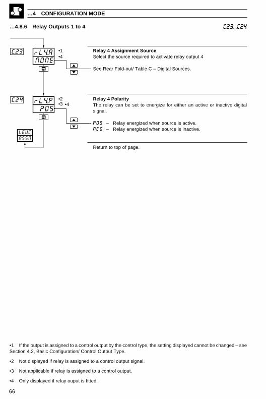
66
…4.8.6 Relay Outputs 1 to 4
…4 CONFIGURATION MODE
C23...C24
Relay 4 Assignment SourceSelect the source required to activate relay output 4
See Rear Fold-out/ Table C – Digital Sources.
Relay 4 PolarityThe relay can be set to energize for either an active or inactive digitalsignal.
POS – Relay energized when source is active.NEG – Relay energized when source is inactive.
Return to top of page.
NONErL4.AC..23
POSrL4.PC.24
•1
•2•3
LEVCASSN
•4
•4
•1 If the output is assigned to a control output by the control type, the setting displayed cannot be changed – seeSection 4.2, Basic Configuration/ Control Output Type.
•2 Not displayed if relay is assigned to a control output signal.
•3 Not applicable if relay is assigned to a control output.
•4 Only displayed if relay ouput is fitted.

67
SErLLEVdd.00
1Addrd.03
NONEPrtYd.02
0S.CFGd.01
SErLLEVd
Level D – Serial Communications Configuration
Note. To select this frame from anywhere in this page, press and holdthe key for a few seconds.
Serial Configuration
0 – Off1 – 2-wire connection, 2400 baud rate2 – 4-wire connection, 2400 baud rate3 – 2-wire connection, 9600 baud rate4 – 4-wire connection, 9600 baud rate5 – 2-wire connection, 19200 baud rate6 – 4-wire connection, 19200 baud rate
Parity
NONE – NoneOdd – OddEVEN – Even
MODBUSTM AddressEach slave on a MODBUS link must be assigned a unique address – seeIM/C500–MOD.
[1 to 99]
Return to top of page.
4.9 Level D – Serial Communications Configuration
Note. Level D is only applicable if the serial communications option is fitted.
d.00...d.03
4 CONFIGURATION MODE…

68
4.10 Level E – Calibration
Note. This page enables fine tuning of the inputs to eliminate system errors.
E.00...E.04
Level E – Calibration
Note. To select this frame from anywhere in this page, press the key for a few seconds.
Analog Input 1 Offset CalibrationAnalog Input 1 Value in Engineering Units
Offset [in engineering Units]
If the and keys are not operated for three seconds the displayreverts to the offset value only.
Analog Input 1 Span CalibrationAnalog Input 1 Value in Engineering Units
Span Adjustment[0.750 to 1.250]
If the and keys are not operated for three seconds the displayreverts to the span value only.
Analog Input 2 Offset CalibrationAnalog Input 2 Value in Engineering Units
Offset [In engineering Units]
If the and keys are not operated for three seconds the displayreverts to the offset value only.
Analog Input 2 Span CalibrationAnalog Input 2 Value in Engineering Units
Span Adjustment[0.750 to 1.250]
If the and keys are not operated for three seconds the displayreverts to the offset value only.
Continued…
…4 CONFIGURATION MODE
CALLEVEE.00
0.0OFF.2E.03
0.0SPn.1E.02
0.0OFF.1E.01
1.0SPn.2E.04
0.0100.3
0.0100.3
0.0100.3
0.0100.3

69
8888OFF.3E.05
8888SPN.3E.06
•1
•1
0.0100.3
0.0100.3
NOC.CAL
E.07
NOO.CAL
E.08
E.09
E.10
FCAL
30r.trV
rEF2700
F.CALAUtO
rEF2700
r.trV 30
Fb.LO 100
NO
AUtO
MAN
•2
•2
•2
•2
Analog Input 3 Offset CalibrationAnalog Input 3 Value in Engineering Units
Offset [In engineering Units]If the and keys are not operated for three seconds the displayreverts to the offset value only.
Analog Input 3 Span CalibrationAnalog Input 3 Value in Engineering Units
Span Adjustment[0.750 to 1.250]
If the and keys are not operated for three seconds the displayreverts to the offset value only.
Position Feedback CalibrationSelect the calibration required.NO – No CalibrationAUtO – Auto Calibration_AN – Manual Calibration
Regulator Travel Time
[0 to 5000 seconds]Ensure that the value entered is compatible with the regulator motor, asthis is used to determine the length of travel of the feedback mechanism.
Motorized Valve Feedback – Fully-closed Position
NO No actionYES Fully closes the valve automatically and sets the electrical input
to low range value.
Note. Input value flashes when calibration is in progress.
Motorized Valve Feedback – Fully-open Position
NO No actionYES Fully opens the valve automatically and sets the electrical input
to high range value.
Note. Input value flashes when calibration is in progress.
Continued in Cold Junction Reference Value frame.
…4.10 Level E – Calibration E.05...E.10
4 CONFIGURATION MODE…
•1 Only displayed if option board is fitted.
•2 Only displayed if Motorized Valve with feedback output type is selected – see Section 4.2, Basic Configuration.

70
…4.10 Level E – Calibration
Position Feedback Electrical Range LowSet the minimum electrical input value.
[0.0 to 999.9]For resistance input types, no decimal places are displayed. For all otherinput types, 1 decimal place is displayed.
Position Feedback Electrical Range HighSet the maximum electrical input value.
[0.0 to 999.9]
Continued in Cold Junction Reference Value frame.
Cold Junction Reference ValueThis value should only be changed if a new CJ sensor is supplied with a CJreference value different to 2700.
The resistance (in Ohms) of the CJ sensor at 25°C.
Cold Junction Beta ValueThis value should only be changed if a new CJ sensor is supplied with a CJBeta value different to 3977.
The beta value of the CJ sensor.
Cold Junction Reading – I/P1 and I/P2The temperature measured by the cold junction sensor is displayed in °C.
Cold Junction Reading – I/P3The temperature measured by the cold junction sensor is displayed in °C.
Return to top of Calibration Level.
100.0Fb.LOE11
500.0Fb.HIE.12
FCAL MAN
rEF2700
Fb.HI 500
2700rEFE.13
3977bEtAE.14
25.2CJ3E.16
LEV.E CAL
O.CAL NO
FCAL NO
•1
•1
25.2 CJ1E.15
•2•3
…4 CONFIGURATION MODE
E.11...E.16
•1 Only displayed if Motorized Valve with feedback output type is selected – see Section 4.2, Basic Configuration.
•2 Only displayed if corresponding input type is set to 'THC'.
•3 Only displayed if option board is fitted.

71
5 INSTALLATION
B – Within Humidity Limits
C – Within Protection Rating Limits
A – Close to Sensor
A – Within Temperature Limits
Caution. Select a location awayfrom strong electrical and magneticfields. If these cannot be avoided,particularly in applications where ‘walkietalkies’ are used, connect usingscreened cables within grounded metalconduit.
D – Use Screened Cables
B – At Eye-level Location
C – Avoid Vibration
EC Directive 89/336/EEC
In order to meet the requirements of the ECDirective 89/336/EEC for EMC regulations, thisproduct must not be used in a non-industrialenvironment.
End of Life DisposalThis instrument does not contain any substancethat will cause undue harm to the environment.However, the unit contains a small lithium battery.This should be removed and disposed ofresponsibly in accordance with local environmentalregulations. The remainder of the unit can besafely considered as normal waste and disposedof accordingly.
5.1 Mechanical Installation5.1.1 Siting – Figs. 5.1 and 5.2
Fig. 5.2 Environmental RequirementsFig. 5.1 General Requirements
55°CMax.
0°CMin.
IP66/NEMA4X(front panel)
IP20(rear)
0 to 90% RH
+
SensorMinimum

72
…5 INSTALLATION
5.1.2 Mounting – Figs. 5.3 to 5.5The instrument is designed for panel mounting (Fig. 5.4). Overall dimensions are shown in Fig. 5.3.
Note. For NEMA4X protection, a minimum panel thickness of 2.5mm is recommended.
Fig. 5.3 Overall Dimensions
149.5 (5.87)
137.5 (5.41)
137.8(5.43)
18(0.71) 76 (2.99)
5.0(0.2)
148(5.83)
Dimensions in mm (in.)
68+0.7–0
(2.68+0.03)–0
30 (1.18)
14 (0.55)
Panel
Cutout138+1
–0
(5.43+0.04)–0
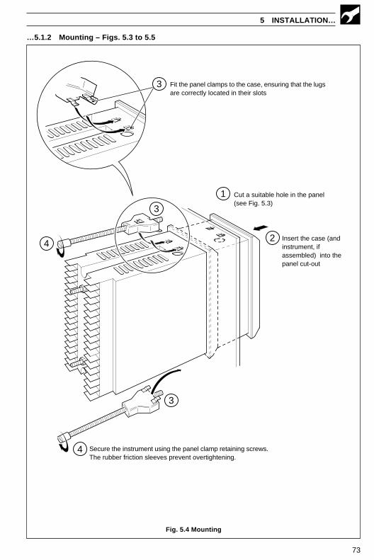
73
5 INSTALLATION…
…5.1.2 Mounting – Figs. 5.3 to 5.5
Fig. 5.4 Mounting
1
4
Cut a suitable hole in the panel(see Fig. 5.3)
Insert the case (andinstrument, ifassembled) into thepanel cut-out
3
Secure the instrument using the panel clamp retaining screws.The rubber friction sleeves prevent overtightening.
4
2
3
3 Fit the panel clamps to the case, ensuring that the lugsare correctly located in their slots
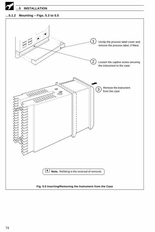
74
…5 INSTALLATION
Fig. 5.5 Inserting/Removing the Instrument from the Case
Note. Refitting is the reversal of removal.
…5.1.2 Mounting – Figs. 5.3 to 5.5
Remove the instrumentfrom the case3
Unclip the process label cover andremove the process label, if fitted.
Loosen the captive screw securingthe instrument to the case
1
2
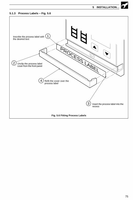
75
5 INSTALLATION…
5.1.3 Process Labels – Fig. 5.6
PROCESS LABEL
Inscribe the process label withthe desired text
Unclip the process labelcover from the front panel
Insert the process label into therecess
Refit the cover over theprocess label
2
1
4
3
Fig. 5.6 Fitting Process Labels
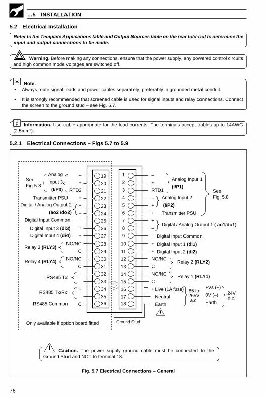
76
…5 INSTALLATION
5.2 Electrical Installation
Refer to the Template Applications table and Output Sources table on the rear fold-out to determine theinput and output connections to be made.
Warning. Before making any connections, ensure that the power supply, any powered control circuitsand high common mode voltages are switched off.
Note.• Always route signal leads and power cables separately, preferably in grounded metal conduit.
• It is strongly recommended that screened cable is used for signal inputs and relay connections. Connectthe screen to the ground stud – see Fig. 5.7.
Information. Use cable appropriate for the load currents. The terminals accept cables up to 14AWG(2.5mm2).
5.2.1 Electrical Connections – Figs 5.7 to 5.9
Caution. The power supply ground cable must be connected to theGround Stud and NOT to terminal 18.
Fig. 5.7 Electrical Connections – General
–
+
RTD2
+
+
–
–
+
+
NO/NC
C
NO/NC
C
+
–
+
–
C
–
+
RTD1
–
+
+
+
–
–
+
+
NO/NC
C
NO/NC
C
+
–
13
14
15
16
17
18
25
26
27
28
29
30
1
2
3
4
5
6
7
8
9
10
11
12
SeeFig. 5.8
85 to265Va.c.
31
32
33
34
35
36
19
20
21
22
23
24
Ground Stud
+Vs (+)
0V (–)
Earth
24Vd.c.
SeeFig 5.8
Analog
Input 3
(I/P3)
Transmitter PSUDigital / Analog Output 2
(ao2 /do2)
Digital Input 3 (di3)
Digital Input Common
Digital Input 4 (di4)
Relay 3 (RLY3)
RS485 Tx
RS485 Tx/Rx
RS485 Common
Relay 4 (RLY4)
Live (1A fuse)
Neutral
Earth
Analog Input 1
(I/P1)
Analog Input 2
(I/P2)
Transmitter PSU
Digital / Analog Output 1 ( ao1/do1)
Digital Input Common
Digital Input 1 (di1)
Digital Input 2 (di2)
Relay 2 (RLY2)
Relay 1 (RLY1)
Only available if option board fitted

77
5 INSTALLATION…
…5.2.1 Electrical Connections – Figs. 5.7 to 5.9
Fig. 5.8 Electrical Connections – Analog Inputs
Fig. 5.9 Electrical Connections – Digital Inputs
* Using internal transmitter power supply
** Use 100Ω shunt resistor provided with instrument
*** Only available if option board fitted
**** For correct broken sensor operation with voltage inputs, fit a 100KΩ pull up resistor
# Fit the CJ sensor supplied if I/P1 or I/P2 are THC inputs
## I/P2 can only be used with THC inputs if I/P1 is also used as a THC input
–
+
–
+
–
+
19
20
21
22
THCmilliVoltsand Volts
– RTD
3rd lead
+ RTD
3-leadRTD
2-lead RTDand Resistance
– RTD
+ RTD
– RTD
milliAmps
**100Ω**100Ω
Tx 2-wireTransmitter
* milliAmps
CJ SensorI/P3 ***
AnalogInput 3
–
+
THCmillivoltsand volts
RTD –
3rd lead
RTD +
3-leadRTD
–
+
Milliamps
1
2
3
4
–
+
* Milliamps
2-wireTransmitter
RTD –
RTD –
RTD +
2-lead RTDand Resistance
**100Ω**100Ω
Tx
Milliamps
–
+
**100Ω
–
+
2-wireTransmitter
**100Ω
–
+Millivolts Tx
5
6
CJ Sensor#
I/P 1
I/P 2THC##
–
+
AnalogInput 1
AnalogInput 2
Voltage
****100Ω
****100KΩ
Voltage
Volt freeInactive Active
TTLInactive
Active
5V
0V
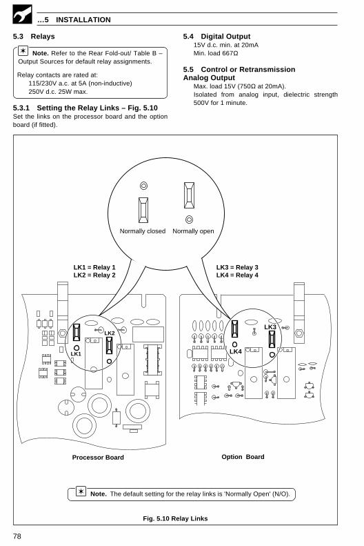
78
5.3 Relays
Note. Refer to the Rear Fold-out/ Table B –Output Sources for default relay assignments.
Relay contacts are rated at:115/230V a.c. at 5A (non-inductive)250V d.c. 25W max.
5.3.1 Setting the Relay Links – Fig. 5.10Set the links on the processor board and the optionboard (if fitted).
5.4 Digital Output15V d.c. min. at 20mAMin. load 667Ω
5.5 Control or RetransmissionAnalog Output
Max. load 15V (750Ω at 20mA).Isolated from analog input, dielectric strength500V for 1 minute.
…5 INSTALLATION
Fig. 5.10 Relay Links
Note. The default setting for the relay links is 'Normally Open' (N/O).
Processor Board
LK3
LK4
Normally openNormally closed
LK1
LK2
Option Board
LK1 = Relay 1LK2 = Relay 2
LK3 = Relay 3LK4 = Relay 4

79
Fig. 5.13 Remote-mounted CJ Sensor –Connections
5.7 Input ConnectionsMake connections to each input – see Fig 5.8.
Refer to Table A on the rear fold-out for thedefault input assignment settings.
5.7.1 Thermocouple (THC) Inputs
Note. Use the correct compensating cablebetween the THC and the terminals – seeTable 5.1.
Automatic Cold Junction Compensation (ACJC) isincorporated by use of CJ sensors wired across theinput terminals of I/P1 and I/P3 – see Fig. 5.12.
Alternatively, the CJ sensor can be mounted remotelyat the point where the thermocouple cable terminatesinto copper cable, e.g. where cables enter aninstrument panel – see Fig. 5.13.
It is possible to use an external fixed cold (reference)junction, if the instrument is programmed for use withmillivolt inputs and the appropriate thermocouplelinearizer is selected. This is only possible via the PCconfigurator.
5 INSTALLATION…
5.6 Motorized Valve Connections – Fig. 5.11
Note. Relays used to drive the motorizedvalve must be set for 'Normally Open' operation –see Section 5.3.1.
Fig. 5.11 Motorized Valve Connections
Note. The wire link must beconnected at the motorized valve end,NOT to the instrument terminals.
0%
100%
MotorizedValveDrive
(N)
N
L
(L)
Motorized ValveDrive
ValvePositioner
PowerSupply
0%
100%
Link
0%
100%
20
19
21
14
15
12
13
–+
A – Relay Connections
Motorized ValveDrive
B – Feedback Connections(V, mA or mV Input Types)
C – Feedback SlidewireConnection
100Ω(mA inputs
only)
19
20
21
D – Alternative FeedbackSlidewire Connection
20
19
Motorized ValveDrive
Link
–
+
1
2
3
Coppercable
I/P1
Compensatingcable
–
+
19
20
21
I/P3
Fig. 5.12 CJ Sensor – Connections
CJ sensor,I/P 3
Fitting theCJ sensor
to I/P 1
Note. Only fit a CJ sensor to I/P 3 ifthe option board is also fitted.
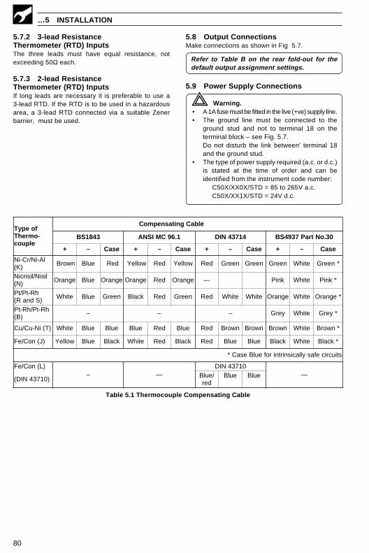
80
…5 INSTALLATION
foepyT-omrehT
elpuoc
elbaCgnitasnepmoC
3481SB 1.69CMISNA 41734NID 03.oNtraP7394SB
+ – esaC + – esaC + – esaC + – esaC
lA-iN/rC-iN)K( nworB eulB deR wolleY deR wolleY deR neerG neerG neerG etihW *neerG
lisiN/lisirciN)N( egnarO eulB egnarO egnarO deR egnarO — kniP etihW *kniP
hR-tP/tP)SdnaR( etihW eulB neerG kcalB deR neerG deR etihW etihW egnarO etihW *egnarO
hR-tP/hR-tP)B( – – – yerG etihW *yerG
)T(iN-uC/uC etihW eulB eulB eulB deR eulB deR nworB nworB nworB etihW *nworB
)J(noC/eF wolleY eulB kcalB etihW deR kcalB deR eulB eulB kcalB etihW *kcalB
stiucricefasyllacisnirtnirofeulBesaC*
)L(noC/eF– —
01734NID—
)01734NID( /eulBder
eulB eulB
5.7.2 3-lead ResistanceThermometer (RTD) InputsThe three leads must have equal resistance, notexceeding 50Ω each.
5.7.3 2-lead ResistanceThermometer (RTD) InputsIf long leads are necessary it is preferable to use a3-lead RTD. If the RTD is to be used in a hazardousarea, a 3-lead RTD connected via a suitable Zenerbarrier, must be used.
5.8 Output ConnectionsMake connections as shown in Fig 5.7.
Refer to Table B on the rear fold-out for thedefault output assignment settings.
5.9 Power Supply Connections
Warning.• A 1A fuse must be fitted in the live (+ve) supply line.• The ground line must be connected to the
ground stud and not to terminal 18 on theterminal block – see Fig. 5.7.Do not disturb the link between' terminal 18and the ground stud.
• The type of power supply required (a.c. or d.c.)is stated at the time of order and can beidentified from the instrument code number:
C50X/XX0X/STD = 85 to 265V a.c.C50X/XX1X/STD = 24V d.c.
Table 5.1 Thermocouple Compensating Cable

81
A1 Single Loop Controller (Templates 1 and 2)
APPENDIX A – CONTROL TEMPLATES
LSP
t
RS
Pt
PID
Con
trol
Loo
pP
ID O
/PC
SP
t
I/P2
LLR
PV
Man
ual O
utpu
t
OP
1
Rem
ote
Set
Poi
nt In
put
Pro
cess
Var
iabl
e In
put
•1Te
mpl
ate
2 O
nly
Set
Poi
ntR
amp
•1I/P
2 xrAtO
+bIAS
I/P1
Loca
l Set
Poi
nt
Sin
gle
Lo
op
Co
ntr
ol
prov
ides
bas
ic fe
edba
ck c
ontr
ol u
sing
thre
e te
rm P
ID o
r On/
off c
ontr
ol. T
he c
ontr
olle
r out
put i
s ca
lcul
ated
from
the
diff
eren
cebe
twee
n th
e pr
oces
s va
riab
le a
nd t
he c
ontr
ol s
et p
oint
. T
he c
ontr
ol s
et p
oint
can
be
a fix
ed v
alue
ent
ered
by
the
user
or
from
a r
emot
e so
urce
.

82
A2 Auto/Manual Station and Analog Backup Station
A2.1 Series and Parallel Operation
Note. See Sections A2.2 and A2.3 for detailed templates.
…APPENDIX A – CONTROL TEMPLATES
Process Variable
di.1
Master Output
ao1
Digital Select
I/P2
PV
Output
Status
Relay 1
ExternalRelay
I/P1
ao1
MasterOutput
Actuator
Process
MasterController
C500
Process Variable
di.1
Master Outputao1
Digital Select
I/P2
PV
Output
Status
I/P1
ao1Actuator
Process
MasterController
C500
Series Connection
Parallel Connection
Fig. A1 Series and Parallel Operation
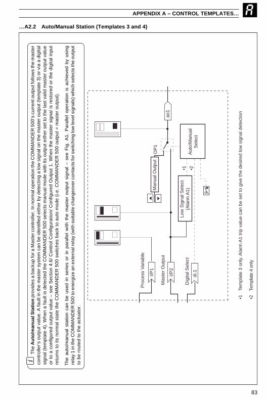
83
APPENDIX A – CONTROL TEMPLATES…
The
Au
to/m
anu
al S
tati
on
pro
vide
s a
back
up fo
r a M
aste
r con
trol
ler.
In n
orm
al o
pera
tion
the
CO
MM
AN
DE
R 5
00’s
cur
rent
out
put f
ollo
ws
the
mas
ter
cont
rolle
r’s
outp
ut v
alue
. A fa
ult i
n th
e m
aste
r sy
stem
can
be
iden
tifie
d ei
ther
by
dete
ctin
g a
low
sig
nal o
n th
e m
aste
r ou
tput
(te
mpl
ate
3) o
r vi
a a
digi
tal
sign
al (
tem
plat
e 4)
. Whe
n a
faul
t is
dete
cted
the
CO
MM
AN
DE
R 5
00 s
elec
ts m
anua
l mod
e w
ith it
s ou
tput
eith
er s
et to
the
last
val
id m
aste
r ou
tput
val
ueor
to
a co
nfig
ured
out
put
valu
e –
see
Sec
tion
4.6/
Con
trol
Con
figur
atio
n/ C
onfig
ured
Out
put
1. W
hen
the
mas
ter
sign
al is
res
tore
d or
the
dig
ital i
nput
retu
rns
to it
s no
rmal
sta
te t
he C
OM
MA
ND
ER
500
sw
itche
s ba
ck t
o au
to m
ode
(i.e
. C
OM
MA
ND
ER
500
out
put
= m
aste
r ou
tput
).
The
aut
o/m
anua
l st
atio
n ca
n be
use
d in
ser
ies
or i
n pa
ralle
l w
ith t
he m
aste
r ou
tput
sig
nal
– se
e F
ig.
A1.
Par
alle
l op
erat
ion
is a
chie
ved
by u
sing
rela
y 1
in th
e C
OM
MA
ND
ER
500
to e
nerg
ize
an e
xter
nal r
elay
(with
sui
tabl
e ch
ange
over
con
tact
s fo
r sw
itchi
ng lo
w le
vel s
igna
ls) w
hich
sel
ects
the
outp
utto
be
rout
ed t
o th
e ac
tuat
or.
Pro
cess
Var
iabl
e
di.1
Aut
o/M
anua
lS
elec
t
Mas
ter
Out
put
ao1
•1 •2
•2
Tem
plat
e 4
only
•1Te
mpl
ate
3 on
ly. A
larm
A1
trip
val
ue c
an b
e se
t to
give
the
desi
red
low
sig
nal d
etec
tion
Dig
ital S
elec
t
Man
ual O
utpu
t
I/P2
Low
Sig
nal S
elec
t(A
larm
A1)
I/P1
OP
1
…A2.2 Auto/Manual Station (Templates 3 and 4)

84
…APPENDIX A – CONTROL TEMPLATES
The
An
alo
g B
acku
p p
rovi
des
a ba
ckup
for
a m
aste
r co
ntro
ller.
In
norm
al o
pera
tion
(rem
ote
cont
rol
mod
e se
lect
ed)
the
CO
MM
AN
DE
R 5
00’s
curr
ent o
utpu
t fol
low
s th
e m
aste
r co
ntro
ller’
s ou
tput
val
ue. A
faul
t in
the
mas
ter
syst
em c
an b
e id
entif
ied
eith
er b
y de
tect
ing
a lo
w s
igna
l on
the
mas
ter
outp
ut (t
empl
ate
5) o
r via
a d
igita
l sig
nal (
tem
plat
e 6)
. Whe
n a
faul
t is
dete
cted
the
CO
MM
AN
DE
R 5
00 s
witc
hes
into
loca
l con
trol
mod
e an
d th
e pr
oces
sis
con
trol
led
by t
he P
ID o
utpu
t of
the
CO
MM
AN
DE
R 5
00.
The
CO
MM
AN
DE
R 5
00 P
ID a
lgor
ithm
con
tinua
lly t
rack
s th
e m
aste
r ou
tput
val
ue t
o en
sure
bum
ples
s tr
ansf
er f
rom
rem
ote
to l
ocal
mod
e op
erat
ion.
Whe
n th
e m
aste
r si
gnal
is
rest
ored
or
the
digi
tal
inpu
t re
turn
s to
its
nor
mal
sta
te t
heC
OM
MA
ND
ER
500
sw
itche
s ba
ck t
o re
mot
e co
ntro
l mod
e (i
.e.
CO
MM
AN
DE
R 5
00 o
utpu
t =
mas
ter
outp
ut).
The
ana
log
back
up s
tatio
n ca
n be
use
d in
ser
ies
or i
n pa
ralle
l w
ith t
he m
aste
r ou
tput
sig
nal.
(See
Fig
. A
1).
Par
alle
l op
erat
ion
is a
chie
ved
by u
sing
rela
y 1
in t
he C
OM
MA
ND
ER
500
to
ener
gize
an
exte
rnal
rel
ay (
with
sui
tabl
e ch
ange
over
con
tact
s fo
r sw
itchi
ng lo
w le
vel s
igna
ls)
whi
ch s
elec
ts t
heou
tput
to
be r
oute
d to
the
act
uato
r.
LSP
t
I/P2
I/P1
di.1
PV
Pro
cess
Var
iabl
e
PID
Con
trol
ler
Low
Sig
nal S
elec
t(A
larm
A1)
Loca
l/R
emot
eS
elec
t
•1 •2
•1
Tem
plat
e 5
only
. Ala
rm A
1 tr
ip v
alue
can
be
set
to g
ive
the
desi
red
low
sig
nal d
etec
tion
•2Te
mpl
ate
6 on
ly.
Mas
ter
Out
put
Dig
ital S
elec
t
Man
ual O
utpu
t
LLR
ao1
OP
1Lo
cal S
et P
oint
A2.3 Analog Backup (Templates 5 and 6)

85
APPENDIX A – CONTROL TEMPLATES
The
Ind
icat
or/
man
ual
Lo
ader
Sta
tio
n is
use
d to
dis
play
one
or
two
proc
ess
vari
able
s on
the
dig
ital a
nd b
argr
aph
disp
lays
. I
f th
e co
ntro
lou
tput
is a
ssig
ned
to a
n an
alog
out
put,
the
low
er d
ispl
ay in
dica
tes
its v
alue
whi
ch c
an b
e ad
just
ed b
y th
e us
er. T
his
outp
ut c
an b
e us
ed to
man
ually
cont
rol a
pro
cess
or
to p
rovi
de a
set
poi
nt v
alue
for
ano
ther
con
trol
ler.
A3 Indicator/Manual Loader Station (Templates 7 and 8)
PV
1
PV
2I/P
2
I/P1
Man
ual O
utpu
tao
1
•1
Tem
plat
e 8
Onl
y
•1
•2
Not
app
licab
le if
Con
trol
Out
put T
ype
is s
et to
'Non
e' –
see
Sec
tion
4.2/
Bas
ic C
onfig
urat
ion.
•2
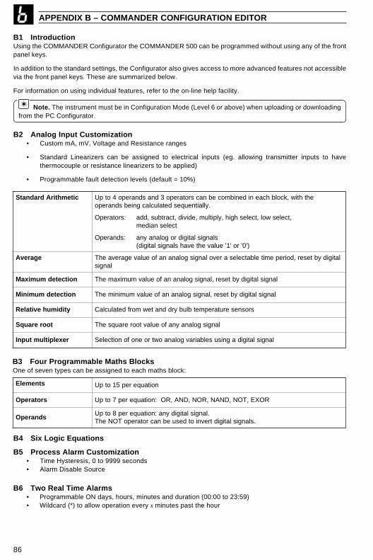
86
APPENDIX B – COMMANDER CONFIGURATION EDITOR
B1 IntroductionUsing the COMMANDER Configurator the COMMANDER 500 can be programmed without using any of the frontpanel keys.
In addition to the standard settings, the Configurator also gives access to more advanced features not accessiblevia the front panel keys. These are summarized below.
For information on using individual features, refer to the on-line help facility.
Note. The instrument must be in Configuration Mode (Level 6 or above) when uploading or downloadingfrom the PC Configurator.
B2 Analog Input Customization• Custom mA, mV, Voltage and Resistance ranges
• Standard Linearizers can be assigned to electrical inputs (eg. allowing transmitter inputs to havethermocouple or resistance linearizers to be applied)
• Programmable fault detection levels (default = 10%)
citemhtirAdradnatS ehthtiw,kcolbhcaenidenibmocebnacsrotarepo3dnasdnarepo4otpU.yllaitneuqesdetaluclacgniebsdnarepo
:srotarepO ,tceleswol,tceleshgih,ylpitlum,edivid,tcartbus,ddatcelesnaidem
:sdnarepO slangislatigidrogolanayna)'0'ro'1'eulavehtevahslangislatigid(
egarevA latigidybteser,doirepemitelbatcelesarevolangisgolananafoeulavegarevaehTlangis
noitcetedmumixaM langislatigidybteser,langisgolananafoeulavmumixamehT
noitcetedmuminiM langislatigidybteser,langisgolananafoeulavmuminimehT
ytidimuhevitaleR srosneserutarepmetblubyrddnatewmorfdetaluclaC
toorerauqS langisgolanaynafoeulavtoorerauqsehT
rexelpitlumtupnI langislatigidagnisuselbairavgolanaowtroenofonoitceleS
B3 Four Programmable Maths BlocksOne of seven types can be assigned to each maths block:
stnemelE noitauqerep51otpU
srotarepO ROXE,TON,DNAN,RON,DNA,RO:noitauqerep7otpU
sdnarepO.langislatigidyna:noitauqerep8otpU
.slangislatigidtrevniotdesuebnacrotarepoTONehT
B4 Six Logic Equations
B5 Process Alarm Customization• Time Hysteresis, 0 to 9999 seconds• Alarm Disable Source
B6 Two Real Time Alarms• Programmable ON days, hours, minutes and duration (00:00 to 23:59)• Wildcard (*) to allow operation every x minutes past the hour

87
Fig. B1 Connecting the COMMANDER PC Configurator
RS232 Serial Port
B7 Two Delay Timers• Programmable delay and duration (0 to 9999 seconds)
B8 Two Custom Linearizers• 15 breakpoints per linearizer• The source can be any analog signal
B9 Template CustomizationEach template can be customized by changing the sources for various functions in the COMMANDER 500. Thisallows maths blocks and custom linearizers to be added into the standard template format.
The following sources can be programmed:• process variable inputs• set point inputs• position feedback input• input to ratio/bias block• ratio inputs• bias inputs
B10 Connecting the COMMANDER PC Configurator
APPENDIX B – COMMANDER CONFIGURATION EDITOR
Note.The COMMANDER 500 must be in the configurationmode (Levels 6 to E) when using the PC Configurator.

88
FRAMES INDEX
Set Up FramesFrame TitleAAlarm 1 TripAlarm 2 TripAlarm 3 TripAlarm 4 TripAlarm 5 TripAlarm 6 TripAlarm 7 TripAlarm 8 Trip
Approach Band 1
CControl Zone DeadbandCycle Time 1Cycle Time 2
DDeadband (Feedback only)Derivative Action Time 1
HHeat/Cool Output 1 StartHeat/Cool Output 2 Start
IIntegral Action Time 1Integral Action Time 2Integral Action Time 3Integral Action Time 4
LLocal Set Point 1Local Set Point 2Local Set Point 3Local Set Point 4
MManual ResetMotorised Valve BiasMotorised Valve Ratio
OOutput 1 On/off Hysteresis ValueOutput 2 On/off Hysteresis Value
PProportional Band 1Proportional Band 2Proportional Band 3Proportional Band 4
RRamp RateRegulator Travel TimeRemote Set Point BiasRemote Set Point Ratio
SSet Points
TTune
VValve Set Up
Mnemonic Number
1.xxx 4.012.xxx 4.023.xxx 4.034.xxx 4.045.xxx 4.056.xxx 4.067.xxx 4.078.xxx 4.08
Ab 1 2.15
S.SPt 2.21CYC1 2.01CYC2 2.02
d.bNd 5.03drV1 2.13
Y1St 2.22Y2St 2.23
IAt.1 2.01IAt.2 2.10IAt.3 2.11IAt.4 2.12
LSP.1 3.01LSP.2 3.02LSP.3 3.03LSP.4 3.04
rSt.1 2.17VbIA 5.02VrAt 5.01
HYS.1 2.03HYS.2 2.04
Pb-1 2.05Pb-2 2.06Pb-3 2.07Pb-4 2.08
r.rtE 3.10r.trV 5.04bIAS 3.07rAtO 3.06
LEV3 3.00
LEV2 2.00
LEV5 5.00
Mnemonic
Frame Number
ParameterSetting/Value
Fig. I.1 Parameter Identification
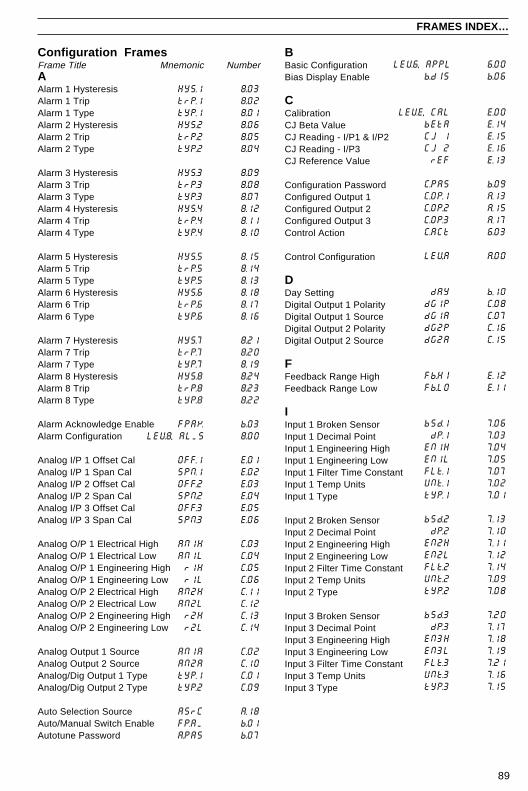
89
FRAMES INDEX…
Configuration FramesFrame TitleAAlarm 1 HysteresisAlarm 1 TripAlarm 1 TypeAlarm 2 HysteresisAlarm 2 TripAlarm 2 Type
Alarm 3 HysteresisAlarm 3 TripAlarm 3 TypeAlarm 4 HysteresisAlarm 4 TripAlarm 4 Type
Alarm 5 HysteresisAlarm 5 TripAlarm 5 TypeAlarm 6 HysteresisAlarm 6 TripAlarm 6 Type
Alarm 7 HysteresisAlarm 7 TripAlarm 7 TypeAlarm 8 HysteresisAlarm 8 TripAlarm 8 Type
Alarm Acknowledge EnableAlarm Configuration
Analog I/P 1 Offset CalAnalog I/P 1 Span CalAnalog I/P 2 Offset CalAnalog I/P 2 Span CalAnalog I/P 3 Offset CalAnalog I/P 3 Span Cal
Analog O/P 1 Electrical HighAnalog O/P 1 Electrical LowAnalog O/P 1 Engineering HighAnalog O/P 1 Engineering LowAnalog O/P 2 Electrical HighAnalog O/P 2 Electrical LowAnalog O/P 2 Engineering HighAnalog O/P 2 Engineering Low
Analog Output 1 SourceAnalog Output 2 SourceAnalog/Dig Output 1 TypeAnalog/Dig Output 2 Type
Auto Selection SourceAuto/Manual Switch EnableAutotune Password
BBasic ConfigurationBias Display Enable
CCalibrationCJ Beta ValueCJ Reading - I/P1 & I/P2CJ Reading - I/P3CJ Reference Value
Configuration PasswordConfigured Output 1Configured Output 2Configured Output 3Control Action
Control Configuration
DDay SettingDigital Output 1 PolarityDigital Output 1 SourceDigital Output 2 PolarityDigital Output 2 Source
FFeedback Range HighFeedback Range Low
IInput 1 Broken SensorInput 1 Decimal PointInput 1 Engineering HighInput 1 Engineering LowInput 1 Filter Time ConstantInput 1 Temp UnitsInput 1 Type
Input 2 Broken SensorInput 2 Decimal PointInput 2 Engineering HighInput 2 Engineering LowInput 2 Filter Time ConstantInput 2 Temp UnitsInput 2 Type
Input 3 Broken SensorInput 3 Decimal PointInput 3 Engineering HighInput 3 Engineering LowInput 3 Filter Time ConstantInput 3 Temp UnitsInput 3 Type
Mnemonic Number
HYS.1 8.03trP.1 8.02tYP.1 8.01HYS.2 8.06trP.2 8.05tYP.2 8.04
HYS.3 8.09trP.3 8.08tYP.3 8.07HYS.4 8.12trP.4 8.11tYP.4 8.10
HYS.5 8.15trP.5 8.14tYP.5 8.13HYS.6 8.18trP.6 8.17tYP.6 8.16
HYS.7 8.21trP.7 8.20tYP.7 8.19HYS.8 8.24trP.8 8.23tYP.8 8.22
FPAK b.03LEV8, ALMS 8.00
OFF.1 E.01SPN.1 E.02OFF.2 E.03SPN.2 E.04OFF.3 E.05SPN.3 E.06
AN1H C.03AN1L C.04r1H C.05r1L C.06
AN2H C.11AN2L C.12r2H C.13r2L C.14
AN1A C.02AN2A C.10tYP.1 C.01tYP.2 C.09
ASrC A.18FP.AM b.01A.PAS b.07
LEV6, APPL 6.00b.dIS b.06
LEVE, CAL E.00bEtA E.14CJ 1 E.15CJ 2 E.16rEF E.13
C.PAS b.09C.OP.1 A.13C.OP.2 A.15C.OP.3 A.17C.ACt 6.03
LEV.A A.00
dAY b.10dG1P C.08dG1A C.07dG2P C.16dG2A C.15
Fb.HI E.12Fb.LO E.11
bSd.1 7.06dP.1 7.03
EN1H 7.04EN1L 7.05FLt.1 7.07UNt.1 7.02tYP.1 7.01
bSd.2 7.13dP.2 7.10
EN2H 7.11EN2L 7.12FLt.2 7.14UNt.2 7.09tYP.2 7.08
bSd.3 7.20dP.3 7.17
EN3H 7.18EN3L 7.19FLt.3 7.21UNt.3 7.16tYP.3 7.15

90
SSerial CommunicationsSerial ConfigurationSet Point ConfigurationSet Point 1 SourceSet Point 2 SourceSet Point 3 SourceSet Point 4 Source
Set Point Default ValueSet Point High LimitSet Point Low LimitSet Point Tracking
Set up PasswordSet Point Adjust Disable
TTemplate ApplicationsTime DisplayTune Select Source 1Tune Select Source 2Tune Select Source 3Tune Select Source 4
LEV7 7.00LC.Sr 9.13FPLr b.02Lr.Sr 9.12
FCAL E.07C.CAL E.09O.CAL E.10F.rEJ 6.06AM.Sr A.16M.Sr1 A.12M.Sr2 A.14
Addr d.03PrtY d.02
OP.LO A.06OP.HI A.05OP1H A.07OP2H A.08OP2L A.09
LEVb, OPEr b.00
LEVC, ASSn C.00OP.Sr A.10SrdS A.11O.tYP 6.02
P.rEC A.01rEC.t A.02PVFA A.03dF.OP A.04
r.dIS b.05r.trV E.08rL1P C.18rL1A C.17rL2P C.20rL2A C.19
rL3P C.22rL3A C.21rL4P C.24rL4A C.23r.SrC 9.14SP.FA 9.06
LEVd d.00S.CFG d.01
LEV9, SEt.P 9.00L.Sr.1 9.08L.Sr.2 9.09L.Sr.3 9.10L.Sr.4 9.11
dF.SP 9.07SPt.H 9.02SPt.L 9.03trCK 9.01
S.PAS b.08S.AdJ b.04
t.APP 6.01t.CLK b.13t1Sr A.19t2Sr A.20t3Sr A.21t4Sr A.22
LLevel HeadingLocal Set Point SourceLocal/Remote EnableLocal/Remote Set Point Source
MMV Calibration selectionMV Feedback – closedMV Feedback – openMains RejectionMan/Auto Selection SourceManual 1 Selection SourceManual 2 Selection Source
MODBUS AddressMODBUS Parity
OO/P Low LimitO/P High LimitOP 1 High LimitOP 2 High LimitOP 2 Low LimitOperator Configuration
Output AssignmentOutput Slew RateOutput Slew Rate DisableOutput Type
PPower Fail Recovery ModePower Fail Recovery TimeProcess Variable Fail ActionPV Fail Default Output
RRatio Display EnableRegulator Travel TimeRelay 1 PolarityRelay 1 SourceRelay 2 PolarityRelay 2 Source
Relay 3 PolarityRelay 3 SourceRelay 4 PolarityRelay 4 SourceRemote Set Point SourceRSPT Fault Action
…FRAMES INDEX

91
INDEX
AAccessories .............................................................. 1Alarms ........................................................... 34, 47
Acknowledge ..................................................... 5Acknowledge enable ....................................... 59Configuration ................................................... 47Hysteresis ................................................. 49, 50Set Up ............................................................. 34Trip Settings .............................................. 34, 47Type ........................................................... 34, 49
Analog Backup Station ..................................... 16, 84Analog Inputs – Level 7 ......................................... 43
Broken Sensor .................................... 44, 45, 46Decimal Point ...................................... 43, 45, 46Engineering Range ............................. 44, 45, 46Calibration ....................................................... 68Failure Action .................................................. 55
Analog Outputs 1 and 2 ......................................... 61See Also: Digital Outputs 1 and 2Electrical Ranges ...................................... 62, 64Engineering Ranges ................................. 62, 64Sources ..................................................... 62, 64
See Also: Rear Fold-out/ Table DAnalog Sources .................... Rear Fold-out/ Table DApproach Band ....................................................... 30Auto-tune ................................................................ 21
Error ................................................................. 21Password ......................................................... 60Starting ............................................................ 23
Auto/ManualMode Selection Source ....................... 56, 57, 58A/M Station Template ............................... 14, 74A/M Switch .................................................. 4, 50
BBargraphs ................................................................. 3
See Also: RelevantOperator Template in Section 2
Basic Configuration – Level 6 ................................ 39Boundless Control – see Motorized ValvesBroken Sensor Drive .................................. 44, 45, 46
CCalibration – see Analog InputsCalibration Error ....................................................... 9Character Set ........................................................... 8Clock Settings ........................................................ 60Cold Junction
Compensation ..................................... 70, 77, 80Failed ................................................................. 9
…CConfiguration Error ................................................... 9Configuration Password ......................................... 60Configured Outputs 1 to 3 ...................................... 57
See Also: Auto/Manual and Backup TemplatesControl Action ......................................................... 42Control Configuration – Level A ............................. 54Control Efficiency Monitor ...................................... 24Control Set Point – see Set PointsControl Output Deadband ...................................... 31Custom Linearizer .................................................. 86
DDate and Time Setting ........................................... 60Deadband
Control Output ................................................. 31MV Feedback .................................................. 35
Default Outputs .......................................... 52, 55, 57Delay Timer ............................................................ 86Derivative Action Time ........................................... 30Deviation Alarms .................................................... 47Digital Inputs 1 to 4 .......................................... 76, 77
See Also: Rear Fold-out/ Table CDigital Outputs 1 and 2 .......................................... 61
Polarity ...................................................... 61, 63Source ....................................................... 61, 63
Digital Sources ..................... Rear Fold-out/ Table CDirect Control Action .............................................. 42Displays ......................................................... 8, 9, 11
LCD Alphabet .................................................... 8
EElectrical Connections ........................................... 76Error Codes .............................................................. 9
FFailure Modes
Analog Input .................................................... 55Power Failure .................................................. 54Process Variable ............................................. 55Remote Set Point ............................................ 52
Fault-finding – see Error MessagesFault Detection Level ............................................. 86Feedback (Motorized Valves) ................................ 35
See Also: Analog Inputs (Process Variable)Filter Time Constant ................................... 44, 45, 46Fine Tuning ...................................................... 25, 68
GGain Scheduling
Selection .......................................................... 58Sources ........................................................... 58Proportional and Integral Terms ..................... 29
Glossary of Abbreviations ...................................... 10

92
…INDEX
HHeat/Cool ................................................................ 19
Control Action ........................................... 40, 42Output limits .................................................... 55Start positions ................................................. 31
HysteresisAlarms .................................................... 47 to 50On/off Control .................................................. 28
IInputs – see Analog InputsInstallation .............................................................. 71Integral Action Time ............................................... 29
KKlaxon Alarms ........................................................ 47
LLatch Alarms .......................................................... 48LEDs ................................................................... 8Linearizers ........................................... 43, 45, 46, 86Line Filter Frequency ............................................. 42Local Set Point – see Set PointsLocal/Remote Key Enable ..................................... 59Local/Remote Mode Selection .............. 6, 16, 52, 53Locking Front Panel Keys ...................................... 59Logic Equations ...................................................... 86Loop Break Monitor ................................................ 10
MMains Rejection Frequency ................................... 42Manual Mode Selection ............................. 56, 57, 59
Pre-set manual output .................................... 57Manual Reset ......................................................... 30Maths Blocks .......................................................... 86Mechanical Installation ........................................... 71MODBUS .......................................................... 67, 76Mounting ................................................................. 72Motorized Valve
Boundless ........................................................ 36Calibration ....................................................... 69Connections .................................................... 79Control Type Selection ................................... 40Feedback ......................................................... 35Regulator Travel Time ........................ 35, 37, 69Set Up ............................................................. 35
OOn/Off Control ........................................................ 28
See Also: Control TypesOperator Configuration – Level B .......................... 59Operating Displays ................................................... 3Operator Ratio/Bias Display Enable ...................... 59Operator Level ........................................................ 11
…OOutput
Assignment – Level C ..................................... 61Connections ........................................ 76, 78, 79Heat/Cool ........................................................ 19Limits ............................................................... 55Slew Rate ........................................................ 56Output SourcesTypes ............................................................... 40
Option Board .......................................................... 76
PPanel Clamps ..................................................... 2, 73PC Configurator ...................................................... 86PID Parameters ................................................ 29, 30
See Also: Gain SchedulingPower Fail Recovery .............................................. 54Power Supplies ................................................ 76, 80Power Up Displays ................................................. 11Process
Alarms ............................................................. 48Labels .............................................................. 75Optimization – see Control Efficiency MonitorVariable – see Analog Inputs
Proportional Band Settings .............................. 29, 30
RRamp Rate (Set Point) ........................................... 33
See Also: Output Slew RateRatio
Ratio Display Enable ...................................... 59Remote Set Point ............................................ 32
Real-time Alarm ...................................................... 86Reference Tables ................................ Rear Fold-outRelative Humidity ................................................... 86Regulator Travel Time – see Motorized ValvesRelay
Connections .................................................... 76Links ................................................................ 78See Also: Output Assignment, Output Types
Remote Set PointFailure Action .................................................. 52Scaling ............................................................. 32Selection Source ............................................. 53
Resistance Thermometer ........................... 43, 46, 76Retransmission – See Analog Outputs,
Analog SourcesReverse Control Action .......................................... 42

93
INDEX
SSecret-til-Lit Indicators ............................................. 8Security Options ..................................................... 60Serial Communications – Level d .......................... 67Set Points
Configuration – Level 9 ................................... 51Default Value ................................................... 52Limits ............................................................... 51Operator Adjust enable ................................... 59Ramp Rate ...................................................... 33Scaling ............................................................. 32Selecting .......................................................... 52Setting – see Relevant Operator TemplateSources ........................................................... 52Tracking ........................................................... 51
Single LoopControllers ........................................... 12, 16, 81, 84Siting ................................................................. 71Short-cut keys .......................................................... 7Slew Rate ............................................................... 56Soft-start – see Set Point Ramp Rate,
Output Slew RateSpan Adjustment – see Calibration
TTemperature Units ..................................... 43, 45, 46Template Applications ................................ 11, 39, 81
Rear Fold-out, Table ATerminals and Connections ................................... 76Thermocouple ............................... 43, 44, 45, 46, 76Time
Setting ............................................................. 60Real-time alarms ............................................. 86Delay Timers ................................................... 86
TuningAutomatic ........................................................ 21Manual ............................................................. 25Tune Parameter Source ................................. 58
UUnits – see Temperature Units
VValve – see Motorized ValveValve Sticking ........................................................... 9
WWarning Messages .................................................. 9Watchdog ............................................................... 10

94
NOTES
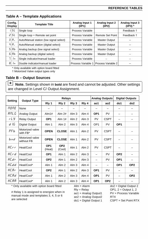
Table A – Template Applications
REFERENCE TABLES
Table B – Output Sources
Note. Settings shown in bold are fixed and cannot be adjusted. Other settingsare changed in Level C/ Output Assignment.
gnitteS epyTtuptuOsyaleR stuptuOgolanA stuptuOlatigiD
1ylR 2ylR 3ylR 4ylR 1oa 2oa 1od 2od
ENON enoN – – – – – – – –
GLNA tuptuOgolanA #1mlA #2mlA 3mlA 4mlA 1PO VP – –
YLr tuptuOyaleR 1PO #1mlA 2mlA 3mlA VP TPSC – –
GId tuptuOlatigiD 1mlA 2mlA 3mlA 4mlA 1PO VP 1PO
bFP evlavdezirotoM*BFhtiw
NEPO ESOLC 1mlA 2mlA VP TPSC – –
dnb evlavdezirotoMBFtuohtiw
NEPO ESOLC 1mlA 2mlA VP TPSC – –
rr.CH looC/taeH1PO
)taeH(2PO
)looC(1mlA 2mlA VP TPSC – –
dr.CH looC/taeH 1PO 1mlA 2mlA 3mlA – VP 2PO –
rd.CH looC/taeH 2PO 1mlA 2mlA 3mlA – VP 1PO –
dd.CH *looC/taeH 1mlA 2mlA 3mlA 4mlA – – 1PO 2PO
rA.CH looC/taeH 2PO 1mlA 2mlA 3mlA 1PO VP – –
dA.CH *looC/taeH 1mlA 2mlA 3mlA 4mlA 1PO VP – 2PO
AA.CH *looC/taeH 1mlA 2mlA 3mlA 4mlA 1PO 2PO – –
.gifnoCyalpsiD
eltiTetalpmeT1tupnIgolanA
)1P/I(2tupnIgolanA
)2P/I(3tupnIgolanA
*)3P/I(
.1 LS poolelgniS elbairaVssecorP †kcabdeeF
.2 LS tnioptesetomeR+poolelgniS elbairaVssecorP tnioPteSetomeR †kcabdeeF
.3 MA )tceleslangiswol(noitatslaunaM/otuA elbairaVssecorP tuptuOretsaM –
.4 MA )tceleslatigid(noitatslaunaM/otuA elbairaVssecorP tuptuOretsaM –
.5 bA )tceleslangiswol(pukcabgolanA elbairaVssecorP tuptuOretsaM –
.6 bA )tceleslatigid(pukcabgolanA elbairaVssecorP tuptuOretsaM –
.7 nI redaollaunam/rotacidnielgniS elbairaVssecorP – –
..8 nI redaollaunam/rotacidnielbuoD 1elbairaVssecorP 2elbairaVssecorP –
dettifdraobnoitpohtiwelbaliavaylnO*ylnosepyttuptuoevlaVdezirotoM†
* Only available with option board fitted
# Relay 1 is assigned to energize when inmanual mode and templates 3, 4, 5 or 6are selected
Alm = AlarmRly = Relayao1 = Analog Output1ao2 = Analog Output2do1 = Digital Output 1
do2 = Digital Output 2OP1, 2 = Output 1, 2PV = Process VariableRTXCSPT = Set Point RTX
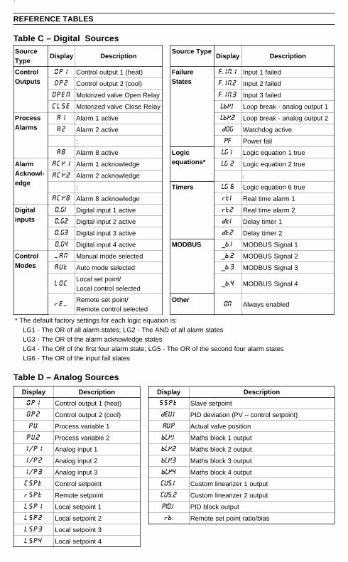
REFERENCE TABLES
yalpsiD noitpircseD yalpsiD noitpircseD
1PO )taeh(1tuptuolortnoC tPSS tnioptesevalS
2PO )looc(2tuptuolortnoC 1VEd )tniopteslortnoc–VP(noitaivedDIP
VP 1elbairavssecorP PVA noitisopevlavlautcA
2VP 2elbairavssecorP 1KLb tuptuo1kcolbshtaM
1P/I 1tupnigolanA 2KLb tuptuo2kcolbshtaM
2P/I 2tupnigolanA 3KLb tuptuo3kcolbshtaM
3P/I 3tupnigolanA 4KLb tuptuo4kcolbshtaM
tPSC tniopteslortnoC 1.SUC tuptuo1reziraenilmotsuC
tPSr tnioptesetomeR 2.SUC tuptuo2reziraenilmotsuC
1PSL 1tniopteslacoL 1DIP tuptuokcolbDIP
2PSL 2tniopteslacoL .br saib/oitartnioptesetomeR
3PSL 3tniopteslacoL
4PSL 4tniopteslacoL
Table C – Digital Sources
Table D – Analog Sources
ecruoSepyT
yalpsiD noitpircseDepyTecruoS
yalpsiD noitpircseD
lortnoCstuptuO
1PO )taeh(1tuptuolortnoC eruliaFsetatS
1.NI.F deliaf1tupnI
2PO )looc(2tuptuolortnoC 2.NI.F deliaf2tupnI
NEPO yaleRnepOevlavdezirotoM 3.NI.F deliaf3tupnI
ESLC yaleResolCevlavdezirotoM 1KbL 1tuptuogolana-kaerbpooL
ssecorPsmralA
1A evitca1mralA 2KbL 2tuptuogolana-kaerbpooL
2A evitca2mralA GOd evitcagodhctaW
: FP liafrewoP
8A evitca8mralA cigoL*snoitauqe
1GL eurt1noitauqecigoL
mralA-lwonkcA
egde
1KCA egdelwonkca1mralA 2GL eurt2noitauqecigoL
2KCA egdelwonkca2mralA :
: sremiT 6GL eurt6noitauqecigoL
8KCA egdelwonkca8mralA 1tr 1mralaemitlaeR
latigiDstupni
1G.D evitca1tupnilatigiD 2tr 2mralaemitlaeR
2G.D evitca2tupnilatigiD 1td 1remityaleD
3G.D evitca3tupnilatigiD 2td 2remityaleD
4G.D evitca4tupnilatigiD SUBDOM 1.b_ 1langiSSUBDOM
lortnoCsedoM
NAM detcelesedomlaunaM 2.b_ 2langiSSUBDOM
tUA detcelesedomotuA 3.b_ 3langiSSUBDOM
COL/tniopteslacoL
detceleslortnoclacoL4.b_ 4langiSSUBDOM
MEr/tnioptesetomeR
detceleslortnocetomeRrehtO NO delbanesyawlA
:sinoitauqecigolhcaerofsgnittesyrotcaftluafedehT*setatsmralallafoDNAehT-2GL;setatsmralallafoROehT-1GL
setatsegdelwonkcamralaehtfoROehT-3GLsetatsmralaruofdnocesehtfoROehT-5GL;etatsmralaruoftsrifehtfoROehT-4GL
setatsliaftupniehtfoROehT-6GL

PRODUCTS & CUSTOMER SUPPORT
A Comprehensive Product RangeAnalytical Instrumentation
• TransmittersOn-line pH, conductivity, and dissolved oxygentransmitters and associated sensing systems.
• SensorspH, redox, selective ion, conductivity anddissolved oxygen.
• Laboratory InstrumentationpH and dissolved oxygen meters and associatedsensors.
• Water AnalyzersFor water quality monitoring in environmental,power generation and general industrialapplications including: pH, conductivity, ammonia,nitrate, phosphate, silica, sodium, chloride,fluoride, dissolved oxygen and hydrazine.
• Gas AnalyzersZirconia, paramagnetic, infrared, thermalconductivity.
Controllers & Recorders• Controllers
Digital display, electronic, pneumatic. Discretesingle-loop and multi-loop controllers which canbe linked to a common display station, processcomputer or personal computer.
• RecordersCircular and strip-chart types (single and multi-point) for temperature, pressure, flow and manyother process measurements.
Electronic Transmitters• Smart & Analog Transmitters
For draft, differential, gauge and absolutepressure measurement. Also, liquid level andtemperature.
• I to P Converters and Field Indicators
Flow Metering• Magnetic Flowmeters
Electromagnetic, insertion type probes andwatermeters.
• Turbine Flowmeters
• Wedge Flow Elements
• Mass Flow MetersTransmitters, sensors, controllers and batch/display units.
Level Control• Submersible, Capacitance & Conductivity.
Pneumatic Instrumentation• Transmitters
• Indicating Controllers
• Recording Controllers
Customer SupportABB Instrumentation provides a comprehensive aftersales service via a Worldwide Service Organization.Contact one of the following offices for details on yournearest Service and Repair Centre.
United KingdomABB Instrumentation LimitedTel: +44 (0)1480 475321Fax: +44 (0)1480 470787
United States of AmericaABB Automation Inc.Tel: +1 716 292 6050Fax: +1 716 273 6207
ItalyABB InstrumentationTel: +39 (0) 344 58111Fax: +39 (0) 344 58278
Client Warranty
Prior to installation, the equipment referred to inthis manual must be stored in a clean, dryenvironment, in accordance with the Company'spublished specification. Periodic checks must bemade on the equipment's condition.
In the event of a failure under warranty, thefollowing documentation must be provided assubstantiation:
1. A listing evidencing process operation andalarm logs at time of failure.
2. Copies of operating and maintenance recordsrelating to the alleged faulty unit.

IM/C
501
Issu
e 5
The Company's policy is one of continuous productimprovement and the right is reserved to modify theinformation contained herein without notice.
© ABB 1999 Printed in UK (6.99)
ABB Instrumentation Ltd.St. NeotsCambs.England, PE19 3EUTel: +44 (0) 1480 475321Fax: +44 (0) 1480 217948
ABB Automation Inc.Instrumentation DivisionPO Box 20550, RochesterNew York 14602-0550USATel: +1 716 292 6050Fax: +1 716 273 6207
ABB Instrumentation22016 LennoComoItalyTel: +39 (0) 344 58111Fax: +39 (0) 344 58278