commentary on part 3 (use and occupancy) of national
TRANSCRIPT

National Research Conseil national 1*1 Council Canada de recherches Canada
Commentary on Part 3 (Use and Occupancy) of the National Building Code of Canada 1985
Issued by the Associate Committee on the National Building Code National Research Council Canada Ottawa
Cop
yrig
ht ©
NR
C 1
941
- 201
9 W
orld
Rig
hts
Res
erve
d ©
CN
RC
194
1-20
19 D
roits
rése
rvés
pou
r tou
s pa
ys
Commentary on Part 3 (Use and Occupancy)
of the National Building Code of Canada
1985
Issued by the Associate Committee on the National Building Code
National Research Council Canada
Cop
yrig
ht ©
NR
C 1
941
- 201
9 W
orld
Rig
hts
Res
erve
d ©
CN
RC
194
1-20
19 D
roits
rése
rvés
pou
r tou
s pa
ys

Commentary on Part 3
Cop
yrig
ht ©
NR
C 1
941
- 201
9 W
orld
Rig
hts
Res
erve
d ©
CN
RC
194
1-20
19 D
roits
rése
rvés
pou
r tou
s pa
ys

Commentary on Part 3
Table of Contents
Preface iii
Chapter 1 Appllcatlon and General Provlslons Application of Part 3 1 Relationship between Part 3 and the National Fire Code 2 General Provisions in Part 3 2
Chapter 2 Scope The Arrangement of Part 3 General Requirements (NBC Section 3.1 ) Size and Occupancy Requirements for Fire Safety (NBC Section 3.2) Safety Requirements within Floor Areas (NBC Section 3.3) Requirements for Exits (NBC Section 3.4) Sewice Spaces (NBC Section 3.5) Health Requirements (NBC Section 3.6) Barrier-Free Design (NBC Section 3.7)
Chapter 3 Concepts and Terrnlnology General What is a Building? Classification of a Building by Major Occupancy Separation of Major Occupancies Construction Types Fire-Resistance Ratings Fire Separations versus Fire-Resistance Ratings Protection of Openings Firewalls Fire Stopping Flame-Spread Ratings Interior Finish Roof Asserrlblies Roof Coverings Occupant Load
Chapter 4 Requlrernents Affectlng the Bulldlng as a Whole General 32 Building Size Determination 32 Structural Fire Protection 35 Spatial Separations 41 Exterior Wall Construction 52
Cop
yrig
ht ©
NR
C 1
941
- 201
9 W
orld
Rig
hts
Res
erve
d ©
CN
RC
194
1-20
19 D
roits
rése
rvés
pou
r tou
s pa
ys

Commentary on Part 3
Equivalent Openings Fire Exposure between Fire Compartments Vertical Fire Spread Fire Alarm Systems Fire and Smoke Detection Systems Fire Department Access Fire Suppression Systems High Buildings Interconnected Floor Space
Chapter 5 Safety wlthin Floor Areas General Access to Exits Suites Corridors Capacity of Access to Exit Assembly Occupancies l nstitutional Occupancies Residential Occupancies Business and Personal Services Occupancies Mercantile Occupancies Industrial Occupancies
Chapter 6 Exl ts General Width of Exits Number of Exits and Travel Distance to Them Distance between Exits Doorways Separation of Exits Flame Spread in Exits Horizontal Exits Fire Escapes
Chapter 7 Servlce Facilltles General Service Rooms Vertical Service Spaces Horizontal Service Spaces
Cop
yrig
ht ©
NR
C 1
941
- 201
9 W
orld
Rig
hts
Res
erve
d ©
CN
RC
194
1-20
19 D
roits
rése
rvés
pou
r tou
s pa
ys

Commentary o n Part 3
Preface
This Commentary contains material to assist the Code user in applying the requirements of Part 3 of the National Building Code of Canada 1985. It has been prepared under the direction of the Standing Committees on Fire Protection and Occupancy of the Associate Committee on the National Building Code, who are also responsible for preparation of the requirements in Part 3 (except Section 3.7) of the National Building Code.
This Commentary describes the overall arrangement of Part 3 and its interrelationship with the National Fire Code of Canada 1985. It discusses the basic concepts and terminology used in Part 3 and provides examples to illustrate and explain a number of the mare complicated requirements.
Comments on this document are welcome and should be addressed to The Secretary, Associate Committee on the National Building Code, National Research Council of Canada, Ottawa, Ontario K1 A OR6.
Ce document est publid en frawais. Les demandes doivent &re adresseds au Secdtaire, Comitd associd du Code national du batiment, Conseil national de recherches Canada, Ottawa, Ontario K1 A OR6.
Cop
yrig
ht ©
NR
C 1
941
- 201
9 W
orld
Rig
hts
Res
erve
d ©
CN
RC
194
1-20
19 D
roits
rése
rvés
pou
r tou
s pa
ys

Commentary on Part 3
Cop
yrig
ht ©
NR
C 1
941
- 201
9 W
orld
Rig
hts
Res
erve
d ©
CN
RC
194
1-20
19 D
roits
rése
rvés
pou
r tou
s pa
ys
Commentary on Part 3 .
COMMENTARY ON PART 3 - . -
(USE AND OCCUPANCY)
OF THE
NATIONAL BUILDING CODE OF CANADA 1985
CHAPTER 1
APPLICATION AND GENERAL PROVISIONS
This commentary has been prepared as a guide for users of Part 3 of the National Building Code (NBC) because of the diversity and complexity of the conditions encompassed by that Part. Part 3 is concerned chiefly with the safety from exposure to fire and the health of the occupants of a building. In using this commentary it is helpful to understand the scope of Part 3 in relation to other Parts of the NBC and the relationship of Part 3 to the National Fire Code of Canada (NFC). The NFC is a separate code prepared under the auspices of the Associate Committee on the National Fire Code.
Appllcatlon of Part 3
Part 3 regulates all buildings classified by major occupancy as Group A, Division 1,2,3,or4, Group B, Division 1 or 2, or Group F, Division 1, regardless of size. It also regulates buildings of all other major occupancies which exceed 600 m2 in area or three storeys in height. Other buildings are regw lated by Part 9, Housing and Small Buildings. In buildings within the scope of Part 9 that contain rooms or spaces used for assembly, institutional, or high hazard industrial occupancy, those rooms or spaces must conform to the applicable requirements of Part 3.
Concerning the installation of building services and equipment, Part 3 regu- lates only those aspects which are not covered by other Parts of the Code. Part 6 contains the requirements for heating, ventilating and air conditioning installations, while Part 7, through reference to the Canadian Plumbing Code, specifies how the appropriate plumbing facilities are to be installed.
Cop
yrig
ht ©
NR
C 1
941
- 201
9 W
orld
Rig
hts
Res
erve
d ©
CN
RC
194
1-20
19 D
roits
rése
rvés
pou
r tou
s pa
ys
Commentary on Part 3
Relations hip between Part 3 and the National Fire Code
A special relationship exists between Part 3 of the NBC and the NFC with respect to fire safety; the content of both Codes must be considered in building design, construction and maintenance. The role of each Code with respect to fire safety can be summarized as follows:
The NBC establishes the standard of fire safety for the construction of new buildings, for reconstruction of existing buildings, including alterations or extensions, and for buildings in which a change in occupancy occurs.
The National Fire Code establishes standards for fire prevention, fire fighting and fire safety in buildings in use, including standards for the conduct of activities causing fire hazards, for maintenance of fire safety equipment and egress facilities, and for portable extinguishers. It limits building contents and requires fire safety plans, which include the organization of supervisory staff for emergency purposes. In addition, the NFC establishes standards for the prevention of fires outside of buildings, which could present a hazard to a community.
The two Codes have been developed as complementary and coordinated documents to reduce to a minimum any conflict in their contents. To ensure their effective application, building and fire officials must be fully conversant with the fire safety standards of both Codes.
General Provisions in Part 3
Part 3 regulates the building under consideration and does not in any way apply to adjacent buildings or properties. The spatial separation requirements in the Code, for instance, use the property line as a base line, rather than the distance between two buildings, if the buildings are located on different properties. In this way each building is regulated independently of buildings on neighbouring properties, but each of those buildings must in turn conform to the same requirements when any construction is undertaken on them.
The requirements of Part 3 are intended to be interpreted and enforced by reasonable people using good judgment. This is especially important for users faced with situations which are not specifically covered in the Code, or in which alternative design solutions are proposed which were not envisaged by the Code committees. There is often insufficient factual knowledge to balance the safety of one set of conditions against another. In the design of any major complex or unusual building, situations arise in which such
Cop
yrig
ht ©
NR
C 1
941
- 201
9 W
orld
Rig
hts
Res
erve
d ©
CN
RC
194
1-20
19 D
roits
rése
rvés
pou
r tou
s pa
ys

Commentary on Part 3
judgments must be made; the Code can never cover all possible situations, though it is revised as experience is gained from its use and additional knowledge obtained through research.
Fire fighting capabilities are assumed to be available in the event of a fire emergency. These capabilities may take the form of a paid or volunteer public fire department or, in some cases, a private fire brigade. Where fire fighting facilities are not available, additional fire safety measures may be required; again, good judgment must be exercised.
Cop
yrig
ht ©
NR
C 1
941
- 201
9 W
orld
Rig
hts
Res
erve
d ©
CN
RC
194
1-20
19 D
roits
rése
rvés
pou
r tou
s pa
ys
Commentary on Part 3
Cop
yrig
ht ©
NR
C 1
941
- 201
9 W
orld
Rig
hts
Res
erve
d ©
CN
RC
194
1-20
19 D
roits
rése
rvés
pou
r tou
s pa
ys
Commentary on Part 3
CHAPTER 2
SCOPE
The Arrangement of Part 3
Part 3 contains seven major sections:
3.1 General 3.2 Size and Occupancy Requirements for Fire Safety 3.3 Safety Requirements within Floor Areas 3.4 Requirements for Exits 3.5 Service Spaces 3.6 Health Requirements 3.7 Barrier-Free Design
General Requirements (NBC Sectlon 3.1)
The requirements in Section 3.1 mainly define concepts that are used throughout the remainder of Part 3. To a large extent this Section is an extension to the definitions section of the NBC, except that some of these concepts or terms are complex. Many of the subjects relate to terms that are defined in an abbreviated form in the definitions Subsection (Subsection 1.3.2.).
Section 3.1 contains the scope of Part 3. It also contains the procedures for the classification of a building according to its use by a major occupancy. Classification is fundamental to the application of other requirements in Part 3. In addition, Section 3.1 contains requirements for combustible construction, heavy timber construction, noncombustible construction, tents and air-sup- ported structures, fire separations, protection of openings, fire walls, fire stops in concealed spaces, flame-spread rating, interior finish, roof assemblies, roof covering, and occupant load. Most of these subjects are also defined terms in Subsection 1.3.2. and are used throughout Part 3, but in a context that includes the additional requirements of Section 3.1. It is from the foundation provided by this Section that many of the requirements of Part 3 have been developed. C
opyr
ight
© N
RC
194
1 - 2
019
Wor
ld R
ight
s R
eser
ved
© C
NR
C 1
941-
2019
Dro
its ré
serv
és p
our t
ous
pays

Commentary on Part 3
Slze and Occupancy Requirements for Fire Safety (NBC Section 3.2)
Section 3.2 includes requirements that affect the building as a whole structure. Approximately two-thirds of the Section contains requirements relating to storey-by-storey fire compartmentation and fire-resistance ratings for load- bearing structura,l asserrrblies and members. These requirements vary in relation to the use of the building, its size, the number of streets it faces, and whether it is sprinklered. Since many of the requirements in this Section depend on the size of the building, details are provided on how building size is determined.
Section 3.2 also specifies the minimum distances between buildings that may affect each other in the event of afire and sets limitson allowable openings and the construction of the building faces. These requirements for the face of a building that may be exposed to fire ot that may expose other buildings to fire are expressed in terms of fire-resistance rating and combustibility, but are not to be confused with the structural fire protection requirementsforthe loadbear- ing structural assemblies mentioned in the preceding paragraph. The structural fire protection requirements ensure that a building will remain structurally intact for agiven period of time after a fire breaks out within it, while the exposing building face requirements are intended to ensure that a fire in one building will not involve another building for a certain period of time.
Requirements are included for public corridors, covered vehicular passage- ways and walkways between buildings. Fire alarm and detection systems are regulated in relation to building size, use and number of occupants. Require- ments relating to fire fighting include provisions for access, water supply, standpipe systems, and sprinkler systems. Other requirements cover emer- gency powerand lighting, and the lightingof exits and areasused by the public.
Section 3.2 includes additional requirements for high buildings. These include smoke control and venting, elevator control, elevators for fire fighters, sprin- klering of certain spaces, central alarm and control facilities, voice communi- cation systems, and emergency power supply for essential equipment.
Additional protection measures are incorporated in Section 3.2 for buildings with openings through the floor assemblies that are not protected by closures (buildings with mezzanines or interconnected floor space).
Cop
yrig
ht ©
NR
C 1
941
- 201
9 W
orld
Rig
hts
Res
erve
d ©
CN
RC
194
1-20
19 D
roits
rése
rvés
pou
r tou
s pa
ys

Commentary on Part 3
. Safety Requirements within Floor Areas (NBC Section 3.3)
Section 3.2 concerns requirements for the entire building. Section 3.3 regulates safety within individual storeys (floor areas), including all rooms and spaces other than service rooms and service spaces covered by Section 3.5. The requirements are grouped according to the occupancy of the floor area, room, or space. This occupancy is not necessarily the major occupancy for which the building is classified.
For example, an office building may be classified as a Group D major occupancy and the provisions for structural fire protection and fire protection equipment for Group D major occupancy buildings prescribed in Section 3.2 apply to the overall building. Within that building, a room or floor area, that is, a subsidiary occupancy, may be used as an assembly, institutional, business, residential, mercantile, or industrial occupancy; in such a case the special rules of Section 3.3 apply to the room or space containing that occupancy. An assembly room must therefore comply with the requirements .for assembly occupancy in Section 3.3, even if it is contained in an office building, hospital, hotel, theatre, industrial building or any other building which would be classified as a major occupancy other than Group A.
In the NBC, life safety for the occupants of any space or floor area depends on the use or occupancy of that space. The risk to these occupants occurs in the early stages of a fire. It is not the same for all occupancies, so each one must be regulated separately. Section 3.3 contains requirements for access to exit both from open floor areas and those floor areas divided into suites. Access to exit includes all portions of the floor area, exclusive of the exit portion. Section 3.3. also regulates the size of access to exits and limits the travel distance to the exitsfromwithin the floor area. Section 3.3 also contains restrictions on the design of guards around openings and in stairways and on the use of glass in doors or windows that may be mistaken for doors.
Requirements for Exlts (NBC Sectlon 3.4)
The requirements for exits are separate from the requirements that affect the building as a whole in Section 3.2 and from the requirements that affect the floor area in Section 3.3. The exit is that part of the escape route that leads from the floor area it serves to anotherbuilding, a public thoroughfare, or a safe open spaceoutside the building. In a typical building with exit stairs, it includes the stairway itself and the doors leading into and out of the stairway. Once in the exit system, a person is considered to be in a relatively safe place, thus
Cop
yrig
ht ©
NR
C 1
941
- 201
9 W
orld
Rig
hts
Res
erve
d ©
CN
RC
194
1-20
19 D
roits
rése
rvés
pou
r tou
s pa
ys

Commentary on Part 3
exiting is generally accomplished without re-entering a floor area in the same building.
Section 3.4 defines what may be used as part of an exit system and the requirements for such facilities, their number and location, fire separation from the rest of the building, and exit signs and lighting.
Setvice Spaces (NBC Section 3.5)
Section 3.5 includes provisions applying to any space that accommodates building services such as chutes, ducts, pipes, or wiring. Also included are requirements affecting attics and crawl spaces, duct spaces, service shafts, service rooms, and concealed spaces in walls and floors. Requirements for these spaces are included in a separate Section because, unlike other parts of a floor area or exit system, they are not usually accessible either to the building occupants or the general public. They are not considered to have any appreciable occupant load and, in many cases, are unoccupied except for occasional inspection or servicing.
Health Requirements (NBC Section 3.6)
Section 3.6 comprises those requirements that affect the health of the occupants. It regulates the number of plumbing fixtures based on occupancy and occupant load and, through reference to other Parts of the Code, the height and area of rooms, natural lighting, and ventilation. Special reference is made to requirements for medical gas systems.
Barrier-Free Deslgn (N BC Sectlon 3.7) The requirements in Section 3.7 affect the design of a building for accessibil- ity to persons in wheelchairs. The primary areas are the approach to a building, entry to and movement within a building, parking, washroom and bathroom layout and design, and special elevator requirements. Measures that address the special needs of persons with physical disabilities that do not restrict them to a wheelchair are included in other Sections of Part 3.
Cop
yrig
ht ©
NR
C 1
941
- 201
9 W
orld
Rig
hts
Res
erve
d ©
CN
RC
194
1-20
19 D
roits
rése
rvés
pou
r tou
s pa
ys

Commentary on Part 3
CHAPTER 3
CONCEPTS AND TERMINOLOGY
General
In this chapter of the commentary, some of the terms and basic concepts that are defined in Subsection 1.3.2. are discussed in further detail. No attempt is made to coverall of the terms that are used; the chapter concentrates on those which give rise to the most misunderstandings.
What Is a Bulldlng?
Various attempts have been made to more precisely define the word building. These attempts have been relatively unsuccessful; the more precise the definition becomes, the more difficult it is to apply. What suits one authority may not suit another. Some common sense, therefore, is necessary in applying the present definition, which merely states that a building is any structure used or intended for supporting or sheltering any use or occupancy.
An authorii adopting the Code may exclude certain specific structures from the provisions of the Code and also exclude structures covered by other legislation. In most cases there is no doubt that a structure is a building, but in a number of instances, a structure might not be classified as a building (e.g., a transmission tower). There is an advantage in maintaining the flexibility of the present definition for those instances where a structure presents a potential danger to the public but would not normally be considered a building.
This occurs most often in industrial uses, particularly in manufacturing facilities and equipment that require specialized design. In structures such as steel mills, aluminum plants, refineries, power generating stations and liquid stor- age facilities, it may be impracticable to follow the specific requirements in Part 3. Awater tank or an oil refinery, for example, has no floor area as defined in the Code, so requirements for exiting from a floor area would not apply. Requirements for structural fire protection in large steel mills, and pulp and paper mills, particularly in certain sections, may not be practicable in terms of the construction normally used in those operations. In other portions of the same building, however, it may be quite reasonable to require that the provisions of Part 3 be applied (e.g., requirements for off ices).
Cop
yrig
ht ©
NR
C 1
941
- 201
9 W
orld
Rig
hts
Res
erve
d ©
CN
RC
194
1-20
19 D
roits
rése
rvés
pou
r tou
s pa
ys

Commentary on Part 3
An area of an industrial occupancy such as an equipment penthouse, which may be occupied only periodically by service staff, would normally not need to have the same type of exit facility as a floor area occupied on a continuing basis. Thus good judgment must be exercised in determining whether to apply a requirement under extenuating circumstances, provided always that the safety of the occupants is not threatened.
One problem with many buildings designs concerns what constitutes part of a building and what does not. A courtyard that is open to the sky but is surrounded by walls, for example, is regulated by the egress requirements in Part 3, but is not normally considered to be part of a building. Where a floor or roof section is cantilevered over ground space and the space below is unenclosed, it is often aquestion of judgment whether the space below should be considered to be part of the building orto be outside the building. Numerous other examples could be cited on this subject, and each situation can present a different aspect of the problem. Since the degree to which certain factors of the building are regulated depends on the limits of the building, these boundaries become quite important in applying the appropriate requirements. There are obviously no simple answers to this complex problem; common sense and good judgment must be exercised in establishing the building limits.
Classification of a Bulldlng by Major Occupancy
The classification of a building by major occupancy is normally the starting point in establishing which Code requirements should apply to that building. This should not be confused with the term occupancy. Major occupancy is defined as the principal occupancy for which a building or part thereof is used or intended to be used, and includes the subsidiary occupancies which are an integral part of the principal occupancy.
For example, if the principal use of a building were educational, the building would be classified as a Group A, Division 2 major occupancy. In addition to the classrooms, the building could contain offices, laboratories, gymnasia, and workshops, which would be considered subsidiary occupancies. Neverthe- .
less, the major occupancy of the building would be Group A, Division 2, and this classification would applywhereverthe requirements for majoroccupancy were specified.
Similarly, in a building whose principal use is manufacturing, the combustible content might require the building to be classified as a Group F, Division 3
Cop
yrig
ht ©
NR
C 1
941
- 201
9 W
orld
Rig
hts
Res
erve
d ©
CN
RC
194
1-20
19 D
roits
rése
rvés
pou
r tou
s pa
ys

Commentary on Part 3
major occupancy. Within the building there could be subsidiary occupancies which are an integral part of the operation of the manufacturing plant, including offices and a cafeteria. These subsidiary occupancies would not normally be considered separate major occupancies; they are subsidiary to the principal occupancy, which is manufacturing.
If a building is used for more than one principal purpose, it must be classified for each major occupancy. For example, the main floor could be used primarily for mercantile operations and several upper storeys could contain offices not related to the mercantile operation. In this case the building would have to be classified for both types of occupancy and would be considered to have two major occupancies (Group D and Group E). Each major occupancy could include subsidiary occupancies.
These examples are relatively clear cut. In other cases the dividing line between a major occupancy and a subsidiary occupancy becomes obscure and judgment must be used to arrive at the appropriate classification. A hotel might have a number of shops on the main floor which might be leased to tenants. Although these shops would serve the clientele of the hotel, as well as other customers, they would not necessarily be subsidiary occupancies of the principal use of the building, which is a residential occupancy providing accommodation for the hotel guests, i.e. a Group C major occupancy. The shops might be considered a second major occupancy classified as Group E. If the hotel contained extensive convention meeting rooms, then there could be a further major occupancy classified as Group A, Division 2.
Except in the case of Group F, Division 1 or 2 major occupancies, if the aggregate area of a major occupancy does not exceed ten percent of the floor area of the storey in which it is located, the building does not have to be classified for that major occupancy for the purposes of determining structural fire protection. This does not exempt these major occupancies from the requirements in Section 3.1 that major occupancies must be separated from each other even though they occupy less than ten percent of the floor area. This provision also does not exempt these small major occupancies from the other requirements of Section 3.2, including spatial separation and fire alarm systems, nor from the requirements of Section 3.3 for specific occupancies. Sufficient information must be included on the plans and in the specifications for a building project to allow the building to be classified by major occupancy and the floor areas to be classified according to their intended use.
The classification of a building by major occupancy is based on the intended use of that building. Subsequent activities of an occasional nature, not
Cop
yrig
ht ©
NR
C 1
941
- 201
9 W
orld
Rig
hts
Res
erve
d ©
CN
RC
194
1-20
19 D
roits
rése
rvés
pou
r tou
s pa
ys
Commentary on Part 3
foreseen in the original design, are not regulated under the specific require- ments of Part 3. These activities may require additional safety measures to ensure that egress paths remain clear of obstructions, that combustible contents are controlled and that fire fighting begins promptly. The National Fire Code includes requirements to address these situations.
Separation of Major Occupancies
Under certain conditions it is necessary to separate one major occupancy f rom another, to protect one from the hazards created by the other. In the case of a Group A major occupancy, where large numbers of persons may be involved, a Group B major occupancy, where persons may be under restraint or receiving medical care, or a Group C major occupancy, where persons may be asleep, it is considered necessary to protect one such occupancy from a hazard created in an adjacent one. The Code therefore requires that each of these major occupancies be protected with a fire separation, having a specified fire-resistance rating, from the other major occupancies. This is to provide sufficient time for evacuating one major occupancy in case of fire in an adjacent one.
In the case of a Group F, Division 1 major occupancy (high hazard industrial), there is a known hazard to be contained. Therefore this major occupancy is required to be isolated from all others by fire separations having specified fire- resistance ratings. In this case, the purpose is to contain the fire within the industrial occupancy and not to protect that occupancy from the effects of fire in another space; however, the fire separation will also control the spread of fire into the Group F, Division 1 major occupancy. Because of the extreme hazard involved, a Group F, Division 1 major occupancy may not be located in a building that contains a Group A, a Group B or a Group C majoroccupancy.
Group E, Group D and Group F, Division 1 and 2 major occupancies do not present as serious a fire risk as a Group F, Division 1 major occupancy. It is not necessary, therefore, to contain these occupancies in the same way. Life safety is not as critical in these major occupancies as it is in Group A, Group B and Group C ma,jor occupancies. The occupants are awake and aware and there are no unusual evacuation problems. In these major occupancies, ,therefore, separation on the basis of major occupancy is not deemed neces- sary. There are of course requirements for separation other than those based solely on ma.jor occupancy. These separation requirements depend on the particular activities within afloor area and are not confined to a particular major
Cop
yrig
ht ©
NR
C 1
941
- 201
9 W
orld
Rig
hts
Res
erve
d ©
CN
RC
194
1-20
19 D
roits
rése
rvés
pou
r tou
s pa
ys

Commentary on Part 3
Construction Types
Many of the requirements throughout Part 3 depend on whether the building is of combustible or noncombustible construction. Buildings over a certain height or area are required to be of noncombustible construction. The building area and building height limits which allowa building to be of combustible construct ion depend on the major occupancy classification, the number of streets the building faces, and whether or not the building is sprinklered. Since combustible construction is defined as construction that does not conform to the requirements for noncombustible construction, it is important at this stage to appreciate what is meant by noncombustible construction, and to differen- tiate this from the term noncombustible as applied to a particular building material.
The terrn noncombustible, applied to a material, means that the material will pass the test for noncombustibility as defined in CAN4-S114, "Standard Method of Test for Determination of Non-Combustibility in Building Materials." This standard constitutes a severe test which a material either passes or fails,
. but is not the sole criterion for judging the acceptability of a building material.
Because the terrn noncombustible applies to a specific product or material, the concept of noncombustible construction is used in the Code. In this type of construction the building asserrrblies are required to be Constructed of noncombustible materials, but the inclusion of certain combustible elements is permitted, specifically those that are listed in Article 3.1.4.5. Where combustible materials are permitted, there are in many cases restrictions on their flame spread properties: For some materials, such as interior finish, restrictions are also placed on the thickness. If an assembly constructed essentially of noncombustible material contains combustible elements not specifically permitted by the Code in noncombustible construction (e.g., combustible cladding), the assembly falls within the category of combustible construction.
Combustible construction is usually considered to be conventional wood frame or heavy timber construction. Conventional wood frame construction is described in detail in Section 9.23 of the NBC. Heavy timber construction is a special category of combustible construction and is acceptable where combustible construction would normally be required to have a h fire- resistance rating. This is achieved by placing minimum limits on the size of columns and beams, as well as on the thickness of floor and roof components. These limits on dimensions, given that this type of construction does not normally contain concealed spaces, provide this construction with a substan-
Cop
yrig
ht ©
NR
C 1
941
- 201
9 W
orld
Rig
hts
Res
erve
d ©
CN
RC
194
1-20
19 D
roits
rése
rvés
pou
r tou
s pa
ys

Commentary on Part 3
tial degree of fire safety. Heavy timber construction is relatively difficult to ignite and, once ignited or subjected to an exposing fire, resists collapse reasonably well. I Under the standard fire test conditions wood will char at an average rate of about 0.64 mm per minute, so that after 40 minutes approxi- mately 25 mm depth of the wood will have been burnt. Therefore, the larger the cross sectional area of the member, the longer the member will maintain its structural stability in a fire.
Tents and air-supported structures are another category of building construc- tion that is regulated in Part 3. Air-s~~pported structures are those whose shapes are maintained through constant air pressure supplied by a blower. These structures must conform to the space separations required for any other structure (except when located on the same property) and to the requirements of Section3.3forfire safetywithinfloorareas andof Section3.4for exits. While these structures do not have to conform to the combustibility and structural fire protection requirements of Section 3.2, since this would obviously be imprac- ticable, they do have to be constructed of a material that will meet ULC-S109, "Standard for Flame Tests of Flame-Resistant Fabrics and Films." This concession.is permitted on the basis that these structures do not contain interior walls, floors, mezzanines or similar construction.
Fire-Reslstance Ratlngs
A fire-resistance rating in Canada is based on Underwriters' Laboratories of Canada standard CAN441 01, "Standard Method of Fire Endurance Tests of Building Construction and Materials." Ina wall or floor furnace, assemblies are subjected on one side to standard conditions intended to simulate a rapidly developing fire. Tested wall assemblies must be not less than 9.3 m2 in area and tested floor assemblies, not less than 16.7 m2 in area. The standard temperature in the furnace reaches 538°C after five minutes, and increases to 904°C after ten minutes, 929°C after one hour, 1 01 0°C after two hours, and 1093OC at the end of four hours.
In this test, a specimen is normally rated on the basis of its ability to pass several criteria. The average temperature on the unexposed side of a wall or floor/ceiling assembly must be not more than 13g°C, but the rise in tempera- ture of a single point can not be more than 181°C. Flames or hot gases that would ignite cotton batting must not pass through the wall or floor assembly, and the assembly must not collapse under a specified load. The period of time at which any one of these criteria is no longer satisfied determines the fire-
Cop
yrig
ht ©
NR
C 1
941
- 201
9 W
orld
Rig
hts
Res
erve
d ©
CN
RC
194
1-20
19 D
roits
rése
rvés
pou
r tou
s pa
ys

Commentary on Part 3
resistance rating of the assembly. In the case of walls and partitions that are intended for a rating of one hour or more, a separate hose stream test is normally undertaken in addition, to determine the ability of the wall to withstand the effects of a hose stream. In the case of columns, all sides of the column are exposed to the temperature of the standard test.
There are a number of similar tests for fire-resistance rating in North America, and the authority having jurisdiction can review results from such tests to determine their acceptability by comparison with the procedures in CAN4- S101.
Chapter 2, "Fire-Performance Ratings," of the Supplement to the National Building Code of Canada 1985 provides methods for determining the fire- resistance rating of many common assemblies constructed with generic building materials. The ratings are largely based on past test results, although theoretical considerations have also been used to extend existing experimen- tal information.
In Canada, Underwriters' Laboratories of Canada and Warnock Hersey Professional Services Limited publish listings of proprietary products and assemblies which have been tested and rated. These listings are valuable sources of information on this subject.
In determining ratings, floorlceiling and rooflceiling assemblies are rated for fire exposure from the underside of the asserr~bly orrly. Interior walls and partitions are rated for fire exposure from each side (one side exposed at a time). Exterior walls, in contrast, are rated for fire exposure only from within the building. Fire-resistance ratings are assigned to combustible as well as noncombustible assemblies, and such ratings depend solely on the ability of the construction to meet the test criteria.
Fl re Separat Ions versus Fire-Resistance Ratlngs
It is important to keep in mind the difference between the terms fire separation and fire-resistance rating. A fire separation is defined as a construction assembly that acts as a bartier against the spread of fire. If an assembly is required to act as a fire separation, then all openings through it must be protected. A fire separation may or may not be required to have a fire- resistance rating. A fire-resistance rating measures the length of time a representative portion of the assembly is able to withstand the conditions of the
d test.
Cop
yrig
ht ©
NR
C 1
941
- 201
9 W
orld
Rig
hts
Res
erve
d ©
CN
RC
194
1-20
19 D
roits
rése
rvés
pou
r tou
s pa
ys

Commentary on Part 3
If a fire separation is required to have a fire-resistance rating of one hour, the requirements are usually expressed in terms of "a fire separation having a fire- resistance rating of not less than 1 h." Slight differences in wording may occur, including the phrase "a 1 hfire separation," but these are all to be read with the same intent. Roofs and exterior walls are not normally required to be fire separations but in many cases are required to have a fire-resistance rating. Exterior walls that present an exposure hazard to adjacent buildings are required to be constn~cted as fire separations, even though they are permitted to have some unprotected openings (see next chapter on spatial separations). No limits are placed on the number of unprotected openings in an assembly that is only required to have a fire-resistance rating, however, openings in exterior walls will affect the required spatial separation between buildings on the same property or the distance between a building and a property line.
In general, floors must act as fire separations, but there are a number of exceptions to this requirement. Floor assemblies over crawl spaces, for example, need not be constructed as fire separations nor have a fire- resistance rating, provided they satisfy certain criteria. In these circum- stances, no fire protection is required for any openings through the floor assembly, since no fire separation is required. In ot her situations openings are permitted through floors to create interconnected lloor space. This subject is considered in more detail under the heading "Interconnected Floor Space." However, in general, openings through floors that could allow fire to spread from one floor to another are required to be protected by shafts, fire dampers or fire stopping, depending on the size and function of the opening. A shaft wall that protects openings through floors is required to have a fire-resistance rating that is related tothefire-resistance rating of the floor assemblies through which it passes.
Protectlon of Openings
A closure is defined as "a device or assembly for closing an opening through a fire separation, such as a door, a shutter, wired glass or glass block, and includes all components, such as hardware, closing devices, frames and anchors." Aclosure may or may not be required to have a fire-protection rating. The term fire-protection rating is used instead of f ire-resistance rating because different criteria are used in determining the rating of a closure. Although the closure is subjected to the same exposure to heat as required in the standard wall and floor tests, the criteria for rating closures are less severe. For example, closures generally do not have to meet the criterion of
Cop
yrig
ht ©
NR
C 1
941
- 201
9 W
orld
Rig
hts
Res
erve
d ©
CN
RC
194
1-20
19 D
roits
rése
rvés
pou
r tou
s pa
ys

Commentary on Part 3
temperature rise on the unexposed face. Exit doors in buildings more than three storeys high, including fire doors in exit shafts, are an exception to this rule. Fire doors opening onto a separated dead end conidorthat provides the only access to exit are also an exception. Temperature rise limits are imposed on these types of doors to ensure that the occupants of a building will be able to pass the fire door without being unduly affected by the heat from a fire. If an exit door is protected by an unoccupied vestibule or corridor, these limits are waived on the assumption that the potential for direct fire exposure is substantially reduced. Doors ,through fire walls have temperature rise limits because of the critical nature of this type of fire separation.
Closures are permitted to have a rating that is less than that required for the wall or floor assembly in which they are located. They normally occupy only a portion of the fire separation and do not have a stnrctural function, so a lower rating can be tolerated without undue overall reduction in fire safety. It is assumed that combustible items will not be stored adjacent to closures.
An exit stair enclosure penetrating a floor required to be a fire separation with a two-hour fire-resistance rating would have to have walls with a two-hourfire- resistance rating; the exit door into the exit stairway would be required to have a 1112 h fire-protection rating and be equipped with appropriate hardware and latches. Exit doors to the exteriir do not need a fire-protection rating unless required for exposure protection.
There are special cases in which 20-minute door assemblies are permitted in fire separations required to provide up to a one-hour fire-resistance rating. A 20-minute fire-protection rating would normally be achieved by a well con- structed 45-mm-thick solid core wood door with a frame and hardware designed to withstand a 20-minute fire test exposure. In general these doors are permitted only in fire separations that do not require a fire-resistance rating of more than h in buildings not more than three storeys in building height, and for suite entrance doors or doors serving classrooms or patients' bed- rooms, provided the fire-resistance rating of the corridor wall is not required to be more than one hour.
If the fire-resistance rating of a floor or roof assembly has been determined on the basis of Chapter 2, "Fire Performance Ratings" of the Supplement to the National Building Code of Canada 1985, and part or all of the required fire- resistance rating is achieved by a protective membrane, such as gypsum board or lath and plaster, openings to ducts through the ceiling membrane may be protected with fire stop flaps. A fire stop flap is a device for maintaining the integrity of the membrane fire protection, whereas afire damper is a device that
Cop
yrig
ht ©
NR
C 1
941
- 201
9 W
orld
Rig
hts
Res
erve
d ©
CN
RC
194
1-20
19 D
roits
rése
rvés
pou
r tou
s pa
ys

Commentary on Part 3
is separately tested and rated to ensure that it will provide a specific fire- protection rating. Fire stop flaps are permitted only when openings are less than 930 cm2 and lead directly into a noncombustible duct. If an opening is less than 130 cm2, the fire stop flap may be omitted, provided the opening leads directly into a noncombustible duct. There are restrictions on the spacing and percentage of openings in the ceiling membrane in any fire compartment. If actual tests conducted on an asserr~bly have demonstrated that other sizes and quantities of openings will not reduce the fire-resistance rating below the required rating, then of course these other openings can be substituted. Figures C-1 , C-2, and C-3 show typical assemblies where fire stop flaps and fire dampers are required.
REQUIRED FlRE
SEPARATIONS
FlRE DAMPERS HEL
OPEN BY FUSIBLE LINKS RESTRICTED AND NEED NOT
VERTICAL FIRE SEPARATION HAVE FIRE STOP FLAPS
Figure C-1
REQUIRED
FIRE { DUCT
SEPARATION
FIRE STOP FLAP BY FUSIBLE LINK
VERTICAL FlRE SEPARATION
Figure C-2
Cop
yrig
ht ©
NR
C 1
941
- 201
9 W
orld
Rig
hts
Res
erve
d ©
CN
RC
194
1-20
19 D
roits
rése
rvés
pou
r tou
s pa
ys

Commentary on Part 3
When membrane ceilings form part of an assembly which is rated by one of the testing laboratories mentioned previously, openings in such ceilings must be protected by those means specifically accepted by the laboratory for that assembly. The generic acceptance of protection for openings in assemblies assigned a rating on the basis of Chapter 2 of the Supplement to the National Building Codeof Canada 1985 does not apply to these proprietary assemblies. For example, recessed fluorescent lighting fixtures must be protected by the methods specified by the testing laboratory.
STRUCTURAL
MEMBERS
/ VERTICAL FIRE SEPARATION FlRE STOP FLAP
CElLING WITH FlRE
RESISTANCE RATING AT
LEAST EQUAL TO VERTICAL
I FlRE SEPARATION
REQUIRED
FlRE
SEPARATION
L I Figure C-3
Portions of a protective membrane which have a lesser rating than that required for the assembly being considered must also be protected to ensure that the membrane continues to perform for the required time. A number of proprietary means have been developed, including the 'tents' for protecting recessed fluorescent lighting fixtures. The purpose of this additional protec- tion is to prevent excessive radiated heat from enteringthe concealed space and causing premature failure of the structural members. The Code does permit minor penetrations for wiring, piping, conduit and electrical boxes without additional protection, but within certain limits.
Cop
yrig
ht ©
NR
C 1
941
- 201
9 W
orld
Rig
hts
Res
erve
d ©
CN
RC
194
1-20
19 D
roits
rése
rvés
pou
r tou
s pa
ys

Commentary on Part 3
Firewalls are special fire separations that divide a building into two or more entities that may be considered individual buildings for the purposes of fire protection. If a building extends across a property line, a dividing wall on the property line must be constructed as a firewall. A firewall may also be constructed within a building on one property and underone ownership for the purpose of applying less stringent fire protection requirements. The building area of each portion is less than that for the whole building, since by definition the building area can be bounded by a firewall. The firewall effectively divides the building into smaller buildings, and the fire safety requirements for the individual portions can be less than for the building as a whole. One exception to this generalized requirement concerns fire alarm systems when there are doorways through a firewall. In this case the fire alarm system must be designed as though the structure were one building.
TRANSVERSE
FOOTINGS OR FOUNDATIONS
AS REQUIRED
Cop
yrig
ht ©
NR
C 1
941
- 201
9 W
orld
Rig
hts
Res
erve
d ©
CN
RC
194
1-20
19 D
roits
rése
rvés
pou
r tou
s pa
ys
Commentary on Part 3
FOOTINGS OR FOLINDATIONS
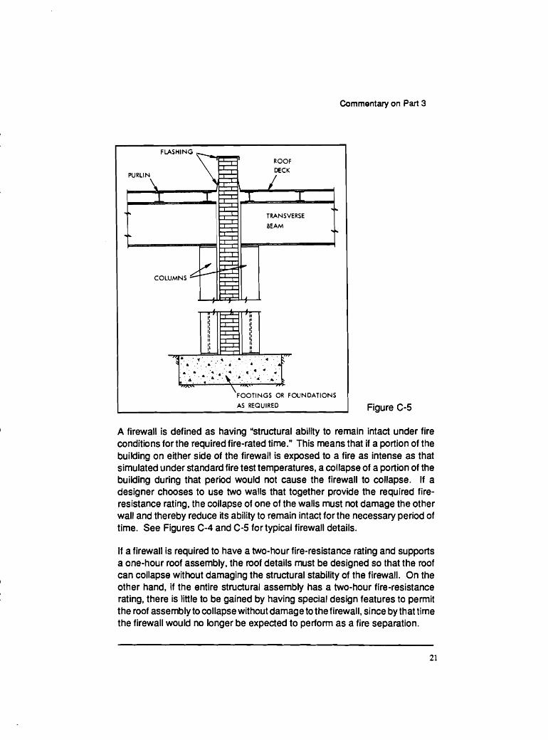
AS REQUIRED Figure C-5
A firewall is defined as having "stmctural ability to remain intact under fire conditions for the required fire-rated time." This means that if a portion of the building on either side of the firewall is exposed to a fire as intense as that simulated under standard fire test temperatures, a collapse of a portion of the building during that period would not cause the firewall to collapse. If a designer chooses to use two walls that together provide the required fire- resistance rating, the collapse of one of the walls must not damage the other wall and thereby reduce its ability to remain intact for the necessary period of time. See Figures C-4 and C-5 for typical firewall details.
If a firewall is required to have a two-hour fire-resistance rating and supports a one-hour roof assembly, the roof details must be designed so that the roof can collapse without damaging the structural stability of the firewall. On the other hand, if the entire structural assembly has a two-hour fire-resistance rating, there is little to be gained by having special design features to permit the roof assembly to collapse without damage to the firewall, since by that time the firewall would no longer be expected to perform as a fire separation.
Cop
yrig
ht ©
NR
C 1
941
- 201
9 W
orld
Rig
hts
Res
erve
d ©
CN
RC
194
1-20
19 D
roits
rése
rvés
pou
r tou
s pa
ys

Commentary on Part 3
Firewalls are required to be constructed so that the required fire-resistance rating is provided by concrete or masonry. Any additional material, such as a protection membrane, does not contribute to the required rating. If a firewall is supported on the structural frame of a building, such as in an offset, the supporting frame must have at least the same fire-resistance rating as the firewall. This does not, however, waive the general rule that firewalls must extend continuously from the footing through all the storeys. If a one-storey portion of a building is adjacent to a three-storey portion, the firewall must extend up the entire three storeys to complete the separation. The only exception to this rule is where the firewall is located above a basement storage garage. In this instance, the firewall may terminate at the floor assembly immediately above the storage garage, provided that floor assembly is constructed as a two-hour reinforced concrete fire separation.
Since firewalls are expected to withstand a complete burnout of any portion of a divided building, the degree of fire resistance required for the firewall depends on the fire load of the adjacent occupancies. In those occupancies with higher fire loads, such as mercantile, or high or medium hazard industrial occupancies, the firewall is required to have a fire-resistance rating not less than four hours. For the occupancies that have lesser fire loads, the fire- resistance rating has to be not less than two hours.
Figure C-6
Cop
yrig
ht ©
NR
C 1
941
- 201
9 W
orld
Rig
hts
Res
erve
d ©
CN
RC
194
1-20
19 D
roits
rése
rvés
pou
r tou
s pa
ys

Commentary on Part 3
Figure C-7
. . . . . . . . . . . . . . . . . . . . 1 , 6 . .:. a . 1 . 4. . ' . . . ; ' . I * . ' . ' * . . . . r . . . . .v'.'... : . . . . ' ' -
Since Tirewalls are intended to prevent the spread of fire across the firewall for the duration of the rating, they are required to extend through the roof and form a parapet above the roof. This parapet must be 150 mm high for a firewall which has a fire-resistance rating of two hours and 900 mm high for a firewall which has a fire-resistance rating of four hours. If the firewall terminates at the underside of a concrete roof slab, a parapet is not required, provided the roof slab has a two-hour fire-resistance rating in the case of a firewall with a rating of four hours and the roof s!ab has a fire-resistance rating of one hour-in the case of a firewall with a fire-resistance rating of two hours (Figures C-6 and C- 7). If the difference in roof elevations on the two sides of the firewall is more than 'three metres, parapets are not necessary.
SMOKE
TIGHT
JOINT
Fire Stopping
Fire stops are elements of building assemblies that are installed at strategic places to resist the passage of fire from one space to another. Typically, fire stops perform two functions. One is to maintain the integrity of a fire separation, such as filling around pipe or duct penetrations. The second function is to limit the size of concealed spaces such as stud or crawl spaces, attics or ceiling spaces.
J
In typical platform type wood frame construction, fire stopping is normally provided by the top and bottom wall plates (Figure C-8). If balloon frame type construction is used, however, fire stops must be placed between the studs to prevent the passage of fire from one storey to another (Figure C-9).
.\2
Spaces between ceiling furring strips in buildings required to be of noncom- bustible construction must be fire stopped to close off any spaces that would allow the spread of fire, if the surface of the ceiling finish material that is
. . 1 .
2 h ROOF SLAB
h FIREWALL 4 h FIREWALL/
1 h ROOF SLAB TIGHT
JOINT
4
. . . .'
. *' s
Cop
yrig
ht ©
NR
C 1
941
- 201
9 W
orld
Rig
hts
Res
erve
d ©
CN
RC
194
1-20
19 D
roits
rése
rvés
pou
r tou
s pa
ys

Commentary on Part 3
Figure C-8
FIRESTOPS
FIRESTOPS
Figure C-9
Cop
yrig
ht ©
NR
C 1
941
- 201
9 W
orld
Rig
hts
Res
erve
d ©
CN
RC
194
1-20
19 D
roits
rése
rvés
pou
r tou
s pa
ys

Commentary on Part 3
Figure C-10
exposed within the concealed space has a flame-spread rating of more than 25. The maximum area of the concealed space is 2 m2. The materials used for this fire-stopping must conform to the requirements of Article 3.1.9.4.
To restrict the spread of fire in an unsprinklered crawl space, the crawl space must be separated into compartments having a maximum area of 600 m2 and a maximum dimension of 30 m. The materials used for this fire-stopping must conform to the requirements of Article 3.1.9.4.
Large concealed spaces, such as attic spaces, must be fire stopped so that the area of individual compartments is not more than 300 m2 for standard combustible construction and not more than 600 m2 if the flame-spread rating of the materials within the space is not more than 25. In concealed spaces within soffits, or gambrel or mansard style roofs, the fire stopping must extend
Cop
yrig
ht ©
NR
C 1
941
- 201
9 W
orld
Rig
hts
Res
erve
d ©
CN
RC
194
1-20
19 D
roits
rése
rvés
pou
r tou
s pa
ys

Commentary on Part 3
into the concealed space beyond the end of any required fire separation. In the case of a fire separation that is required to be noncombustible, no combustible material is permitted to extend around the end of the fire separation. The space between the upper and lower levels of a gambrel or mansard style roof must also be firestopped (Figure C-10).
A variety of materials can be used for fire stopping. The basic requirement is that the material remain in place and prevent the passage of flames when installed in a typical assembly and subjected to the exposure conditions of Underwriters' Laboratories of Canada standard CAN4-S101, "Standard Met hod of Fire Endurance Testsof Building Construction and Materials." The duration of the test is 15 minutes for fire stopping for concealed spaces, but for fire stopping around penetrations of afire separation, the duration depends on the fire-protection rating that would be required for closures. If a building is of noncombustible construction, the fire stopping must be noncombustible unless it conformsto the performance requirementsof the standardorconsists of gypsum board or wood furring strips used to attach finish materials.
Typically in combustible construction, combustible materials are used. In the case of fire stopping of small concealed spaces, such as between furring strips or floor sleepers, or at floor levels, 38-rnm-thick lumber is commonly used, particularly with wood frame construction (Figure C-1 1 ). In larger spaces, such as attic spaces or spaces within gambrel or mansard roofs, sheet materials such as plywood, waferboard or gypsum board are used.
FLOOR JOIST
VERTICAL FURRING
WALL FINISH
Cop
yrig
ht ©
NR
C 1
941
- 201
9 W
orld
Rig
hts
Res
erve
d ©
CN
RC
194
1-20
19 D
roits
rése
rvés
pou
r tou
s pa
ys

Commentary on Part 3
Flamespread Ratlngs
Flame-spread ratings are specified in various articles in Part 3 to control the surface burning characteristics of building materials. The flame-spread rating of a building material is determined by standard tests (CAN4-S102 and CAN4- S102.2) in which the specimen is mounted in a test chamber with a gas burner at one end directing a flame at the specimen; a draft is induced at the opposite end. In the case of CAN4-S102, the underside of the specimen is exposed to the flame. For materials intended to be installed horizontally with the top surface exposed to air (such as carpets or attic insulation), materials that are not self supporting in the test apparatus (such as loose fill insulation), and materials that are thermoplastic, the top surface is exposed to the flame. Carpet material intended for application on floors is tested to CAN4-S102.2, whilecarpet material intended for application on walls is tested to CAN4-S102.
A flame-spread rating is calculated according to the speed at which flame travels along the test specimen or the maximum distance that a flame travels in a given period of time. The rating system is complex, but essentially it attempts to compare the rate of flame travel along the surface of a material against two standard materials: red oak is 100 and asbestos cement board is 0. For example, ordinary gypsum board on this scale would have a flame- spread rating of 10 to 30, and 19-mm-thick untreated, unfinished softwood lumber would have a flame-spread rating of 65 to 150, depending on the species of wood. The standard flame-spread test equipment can also provide comparative values for smoke developed and fuel contributed ratings, again using red oak as 100 and asbestos cement board as 0. Fuel contributed ratings are not used to determine requirements for materials regulated by the NBC.
Flame-spread requirements are employed in several areas of the Code to control the characteristics of building materials. In noncombustible construc- tion, for example,flame-spread limits are specified for many of the combustible elements permitted in these buildings. Any fire retardant treatment process for certain corr~bustible materials used in noncombustible construction is required to penetrate the material rather than be merely a surface application, and the flame spread limit is applies to "any exposed surface or any surface that would be exposed by cutting through the material in any direction." Fire-retardant- treated wood roof systems, which are permitted in lieu of unrated noncom- bustible construction, also have flame spread requirements to limit the propensrty of the material to propagate flame. Fire retardant treatment processes do not significantly improve the fire-resistance rating of an assem-
Cop
yrig
ht ©
NR
C 1
941
- 201
9 W
orld
Rig
hts
Res
erve
d ©
CN
RC
194
1-20
19 D
roits
rése
rvés
pou
r tou
s pa
ys

Commentary on Part 3
bly, nor do they reduce the fire load that is contributed by the combustible material. The treatment process normally only changes the surface burning characteristics of the material.
lnterlor Flnlsh
In general, flame-spread rating requirements apply to interior finish materials and are more restrictive in the critical areas of a building, such as public corridors and exits. Ratings are generally more restrictive for ceilings than for walls. Flame-spread requirementsfor surfaces also depend on the occupancy of the room or space, with more restrictive requirements for institutional and assembly occupancies.
In high buildings (Subsection 3.2.6.), there are additional restrictionson flame- spread rating of interior finish materials. The restrictions apply only if the building is not sprinklered. Where additional flame-spread rating require- ments are specified for high buildings, restrictions on smoke developed classiqfication are also specified. These additional limits on flame-spread rating and smoke developed classification apply only to the more critical areas of these buildings, including public corridors, service rooms, elevator cars, elevator and exit lobbies, and exit stairs and adjacent vestibules. The flame- spread rating for -floor surfaces in these specific areas is also regulated.
All carpeting material must meet a ''flame resistance test" whereby a small combustible pellet of standard chemical composition is ignited on the surface to be tested. This is regulated under the Hazardous Products Act. If the fire or charring produced by the pellet is confined to certain specified limits of the test specimen, the carpet has passed the test. This test determines ignitability from a small ignition source rather than flame resistance and does not measure smoke production.
For certain building materials, including some foamed plastic insulations, the standard flame-spread test may not measure the relative hazard of the material in an actual fire. These materials must be protected by other less hazardous materials; the manner depends on the flame-spread rating of the material and the size of the building.
Cop
yrig
ht ©
NR
C 1
941
- 201
9 W
orld
Rig
hts
Res
erve
d ©
CN
RC
194
1-20
19 D
roits
rése
rvés
pou
r tou
s pa
ys

Commentary on Part 3
Roof Assem bl les
Specific requirements are included for two different types of roof deck assemblies. One assembly is a fire retardant treated wood roof system that is permitted in smaller buildings of combustible construction in place of a combustible mof system having a fire-resistance rating. Limits are placed on the type of supporting structure that can be used. The other assembly that has specific requirements is a metal roof deck system which is overlaid by a material that could lead to a propagating fire under the deck. Both of these systems have to be tested in accordance with Undennrriters' Laboratories of Canada standard ULC S-126M, "Standard Method of Test for Fire Spread under Roof Deck Assemblies." The test is not required on a metal roof deck assembly that has a fire-resistance rating of 3/4 h, or where a thermal barrier protects combustible material above the roof deck from effects of fire in the space below the deck.
Roof Coverlngs
In general, Part 3 requires that all roof surfaces meet the requirements for Class A, B, or C roofs. If a rating is required, the Code does not differentiate between Class A, B, or C ratings; any one is acceptable. Class C is the lowest rating, about equivalent to the spread of flame over the surface of asphalt shingles. Untreated wood shingles would not meet the requirements of Class C. One exception is included in the Code but it applies only to Group A, Division 2 assembly occupancy buildings not more than 1000 m2 in building area and not more than two storeys in building height.
The standard Canadian test and rating procedure for mof surfaces is ULC- S107, Test Method for Fire Resistance of Roof Covering Materials." In this test, the upper surfaces of roof coverings are subjected to aflame. In addition, other samples are subjected to a 'burning brand' test to measure their ability to withstand the effect of flying brands. A Class A roof covering provides more resistance to the spread of flame and burning brands than does a Class B or Class C roof covering.
Cop
yrig
ht ©
NR
C 1
941
- 201
9 W
orld
Rig
hts
Res
erve
d ©
CN
RC
194
1-20
19 D
roits
rése
rvés
pou
r tou
s pa
ys

Commentary on Part 3
Occupant Load
The concept of occupant load in Part 3 sometimes leads to misunderstand- ings. Occupant load is the number of persons for which a building or part of a building is designed. The principal application of occupant load is to determine the number and width of exit facilities that must be provided, as well as the width of access routes leading to exits from within floor areas. Occupant load is also used to determine the number of sanitary fixtures required in washrooms and whether a fire alarm system or.emergency lighting must be installed. It is also one of the parameters used in establishing whether a building is subject to the additional requirementsfor high buildings in Subsec- tion 3.2.6.
Occupant load must be determined on the basis of the total numberof persons that the building or part of the building will accommodate. Occupants of sewice spaces, such as furnace rooms and electrical equipment rooms, and transitory occupants of areas such as access corridors and washrooms, would not normally be counted in determining the occupant load, since any occupants of these areas would have already been included in the occupant load in the regularly occupied parts of the building.
As a general rule the occupant load must be wt less than that determined from Table 3.1.14.A. This table shows the area assumed to be occupied per person, so that the total occupant load can be calculated. However, due to the large potential variation in population densities in most of the categories listed, it is very difficult to establish hard and fast rules for each category. For this reason, some deviation from these values may be justified if the area is to be occupied by fewer persons. In manufacturing and process rooms, for example, a value of 4.6 m2 per person is shown. Depending on the type of manufacturing operation and the degree of automation, this value can vary widely and could be excessively restrictive. In cases such as this, the occupant load estimates may be relaxed from those calculated from the table, provided there is reasonable assurance that the occupant load will not be exceeded in the future. On the other hand, if the occupant load exceeds the values determined from the table, the higher values must be used.
Table 3.1.14.A. is not intended to limit the number of persons that can occupy an area, although it is sometimes interpreted this way. For example, even though the table lists 9.3 m2 per person for offices, it is quite permissable to have offices that provide less space per person. In this caselathe occupant load of the offices would be higher than that normally anticipated and the higher value would be used for Code purposes. However, other legislation may
Cop
yrig
ht ©
NR
C 1
941
- 201
9 W
orld
Rig
hts
Res
erve
d ©
CN
RC
194
1-20
19 D
roits
rése
rvés
pou
r tou
s pa
ys

Commentary on Part 3
govern the maximum number of persons permitted in certain occupancies, and this legislation would be outside the jurisdiction of a building inspector, unless the inspector has been given enforcement powers under the other legislation.
In general the values listed in Table 3.1.14.A. apply to those areas intended for occupancy, including 'the space occupied by fixtures. In the case of mercantile occupancies, for example, the area per person shown in the table includes the areas occupied by the products and display counters, as well as the aisle space.
A storage area for a mercantile operation that is separate from the area accessible to the public would have to be treated separately and would nbrmal~y be considered warehouse space. In certain cases, however, the occupant load of certain non-occupied rooms must be considered in relation to the egress requirements from that room. For example, in industrial occupancies, where washrooms and osther spaces can be extensive and able to accommodate one or even two entire shifts of employees, the egress requirements from these special spaces would have to be adequate for the number of persons who could be expected to use the space at any one time.
A lunch room or a cafeteria in a factory would have to have egress facilities to accommodate the anticipated occupant load from that room. However, the occupant load of the cafeteria wou Id not have to be added to the occupant load of the general factory area, in determining the total occupant load of the building since this would in effect be counting the same people twice. The same situation could arise in a school auditorium. The occupant load of the auditorium, if it is to be used exclusively for the students of the school, would not have to be added to the occupant load of the classrooms in determining the total occupant load of the school. Common sense has to be exercised as to how the occupants use a building in order to calculate the egress require- ments throughout the building. If a cafeteria, gymnasium, or similar facility is available for use by persons other than the usual occupants of the building, then the occupant load of that space would have to be added to the occupant load of other parts of the building.
Cop
yrig
ht ©
NR
C 1
941
- 201
9 W
orld
Rig
hts
Res
erve
d ©
CN
RC
194
1-20
19 D
roits
rése
rvés
pou
r tou
s pa
ys

Coninientary on Part 3
CHAPTER 4
REQUIREMENTS AFFECTING THE BUILDING AS A WHOLE
General
Previous chapters of this commentary have dealt with the general arrange- ment of Part 3 and with concepts and terminology used to develop its requirements. There would have been some advantage in having all the concepts and terminology explained in the same chapter. However, following the general arrangement of Part 3, some of the terminology and concepts are included in this chapter as well. Chapter 4 applies to the requirements in Section 3.2 of the Code that are concerned with structural fire protection by fire-resistance rating for structural members and by fire compartmentation.
Buildlng Slze Determinatlon
Since the structural fire protection requirements, as well as the scope of Part 3, depend on the building size, the Code user must be familiar with how the building size is determined. Throughout Part 3, many requirements are dependent on building height and on building area as defined in the Code.
Building area is the greatest horizontal area of a building above grade within the outside surface of exterior walls or within the outside surface of exterior walls and the centre line of firewalls (Figure D-1). Asdescribed previously, the building area may be altered by the judicious use of firewalls.
BUILDING AREA
WOULD BE AREA
OF 3rd STOREY
Figure D-1
Building height is the number of storeys contained between the roof and the floor of the first storey. The first storey in turn is the uppermost storey having its floor level not more than 2 m above grade (Figure D-2). Thus, a building
Cop
yrig
ht ©
NR
C 1
941
- 201
9 W
orld
Rig
hts
Res
erve
d ©
CN
RC
194
1-20
19 D
roits
rése
rvés
pou
r tou
s pa
ys

Commentary on Part 3
Figure 0-2
- I,. w -
C J
F I R S T S T O R E Y
d
F I R S T S T O R E Y
I \ /
L- - - - - - - - - - - - - - - - - -J
G R A D E
L---- ------ ----------4 rm
Cop
yrig
ht ©
NR
C 1
941
- 201
9 W
orld
Rig
hts
Res
erve
d ©
CN
RC
194
1-20
19 D
roits
rése
rvés
pou
r tou
s pa
ys

Commentary on Part 3
with two storeys above the first storey is a three-storey building. Grade is also defined and means the lowest of the average levels of finished ground adjoining each exterior wall of a building (localized depressions such as for vehicle and pedestrian entrances need not be considered in determining average levels of finished ground). All three definitions are necessary in establishing the height of a building in storeys (Figure 0-3). Establishing grade can pose problems for the authority having jurisdiction, since in certain large complexes it is extremely difficult to determine where the grade should be or where the ground level is. The setting of the grade artificially high in order to diminish the building height, such as by the use of landscaping or grading around the building, is shown in Figure D-4. This could mean the difference between requiring noncombustible construction or permitting combustible construction, or it could mean the difference between requiring a one-hour or a two-hour fire-resistance rating for the structural assemblies. 'Therefore, reason and judgment must be exercised in establishing grade, taking into account such things as exiting and fire fighting.
In the calculation of building height, any penthouse for service equipment is not normally considered a storey. If a mezzanine is built as an open floor area (i.e. without partition walls) and has no visual obstructions above or below it (except
Figure D-4
Cop
yrig
ht ©
NR
C 1
941
- 201
9 W
orld
Rig
hts
Res
erve
d ©
CN
RC
194
1-20
19 D
roits
rése
rvés
pou
r tou
s pa
ys

Commentary on Part 3
for the portion within 1070 mm of the floor), it need not be considered a storey, provided it does not occupy more than 40 percent of the floor area, not including the area of the mezzanine itself (Figure 0-5). The qualifications affecting visual obstruction apply to the spaces above and below the meua- nine. If a mezzanine is enclosed or is visually obstructed and it exceeds 10 percent of the floor area, it must be considered a storey for determining building height in storeys (Figure 0-6). Where there is more than one level of mezzanine, each additional level must be considered a storey for determining building height in storeys (Figure 0-7).
BUILDING WOULD BE
CONSIDERED AS A SECTION VIEW
3 STOREY BUILDING IF
MEZZANINE NOT MORE
THAN 40% OF TCTAL
FLOOR AREA No t more than 1070 mm
I NO PARTITIONS ) Visually unobstructed I No t more than 1070 mm
I //A\\ f l / / \\\"'
I I
Figure 0-5
BUILDING WOULD BE
CONSIDERED AS A
1 STOREY BUILDING IF VISUAL OBSTRUCTIONS
MEZZANINE NOT MORE >
THAN 10% OF TOTAL
FLOOR AREA SECTION VIEW
\ ''fl
Figure 0-6
Structural Flre Protection
One of the main purposes for classifying a building by major occupancy is to establish structural fire protection requirements to ensure that it will withstand collapse under a specified fire exposure and to provide floor-to-floor compart- mentation for this same exposure. The classification of a building by major occupancy relates to the potential fire load. To counteract the effects of this
Cop
yrig
ht ©
NR
C 1
941
- 201
9 W
orld
Rig
hts
Res
erve
d ©
CN
RC
194
1-20
19 D
roits
rése
rvés
pou
r tou
s pa
ys
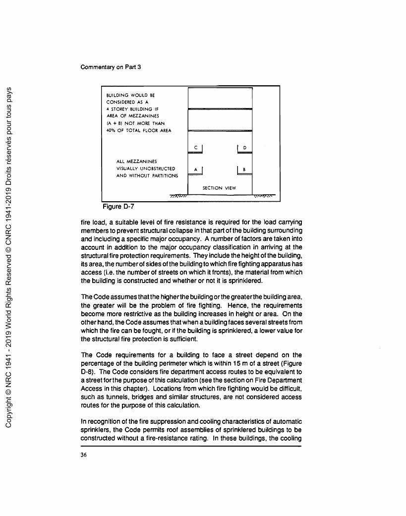
Commentary on Part 3
Figure D-7
BUILDING WOULD BE
CONSIDERED AS A
4 STOREY BUILDING IF AREA OF MEZZANINES
(A + B) NOT MORE THAN
40% OF TOTAL FLOOR AREA
ALL MEZZANINES
VISUALLY UEJOBSTRUCTED
AND WITHOUT PARTITIONS
fire load, a suitable level of fire resistance is required for the load carrying members to prevent structural collapse in that part of the building surrounding and including a specific major occupancy. A number of factors are taken into account in addition to the major occupancy classification in arriving at the structural fire protection requirements. They include the height of the building, its area, the number of sides of the building to which fire fighting apparatus has access (i-e. the number of streets on which it fronts), the material from which the building is constructed and whether or not it is sprinklered.
F m
D - C
A B
SECTION VIEW
\\'''I x''
The Code assumes that the higherthe building or the greaterthe building area, the greater will be the problem of fire fighting. Hence, the requirements become more restrictive as the building increases in height or area. On the other hand, the Code assumes that when a building faces several streets from which the fire can be fought, or if the building is sprinklered, a lower value for the structural fire protection is sufficient.
The Code requirements for a building to face a street depend on the percentage of the building perimeter which is within 15 m of a street (Figure D-8). The Code considers fire department access routes to be equivalent to a street forthe purpose of this calculation (see the section on Fire Department Access in this chapter). Locations from which fire fighting would be difficult, such as tunnels, bridges and similar structures, are not considered access routes for the purpose of this calculation.
In recognition of the fire suppression and cooling characteristics of automatic sprinklers, the Code permits roof assemblies of sprinklered buildings to be constructed without a fire-resistance rating. In these buildings, the cooling
Cop
yrig
ht ©
NR
C 1
941
- 201
9 W
orld
Rig
hts
Res
erve
d ©
CN
RC
194
1-20
19 D
roits
rése
rvés
pou
r tou
s pa
ys

Commentary on Part 3
77% OF PERIMETER PLAN VIEW
LESS THAN 15 m
FROM STREET I FACING 3 STREETS
Figure 0-8
effect of the sprinklers will keep the temperatures of a noncom~bustible roof assembly below those temperatures which would cause the assembly to collapse and will reduce the possibility of a combustible roof assembly being involved in spread of fire. The Code does require that when this option is used the sprinkler system is electrically supervised and the fire department will receive a signal from the building if the sprinkler system operates.
Traditional practice has had a considerable role in tempering the requirements for structural fire protection. There was a considerable element of judgment exercised by the committees involved in establishing the degree of structural fire protection required for a particular set of circumstances. A number of agencies throughout the world are currently developing methodologies for computing fire protection.
In establishing the structural fire protection requirements for a building of a particular size and occupancy, a number of choices are usually available to the
Cop
yrig
ht ©
NR
C 1
941
- 201
9 W
orld
Rig
hts
Res
erve
d ©
CN
RC
194
1-20
19 D
roits
rése
rvés
pou
r tou
s pa
ys
Commentary on Part 3
owner. In Subsection 3.2.2., which contains the structural fire protection requirements, a particular building may be regulated under several Articles. The owner is permitted to select the particular Article (but not parts of different Articles) that will provide the least restrictive requirements for the building.
For example, a three-storey office building having a building area of 4000 rn and facing two streets could be regulated underthree different Articles. It could be regulated as Group D, up to three storeys, as Group Dl up to six storeys, or as Group Dl any height, any area. If it were regulated under the first option as Group Dl up to three storeys (Article 3.2.2.31 .), the building could be of combustible construction having structural fire protection to provide a 3/4 h fire- resistance rating, providing the building were sprinklered to meet the area limitations of the Article. On the other hand, if the second option were used to regulate the building under Group Dl up to six storeys (Article 3.2.2.32.), the building would have to be of noncombustible construction, with structural fire protection to give a fire-resistance rating of not less than one hour, but it would not have to be sprinklered to meet the area limits of this Article. If the building were constructed under Group Dl any height, any area (Article 3.2.2.33.), then it would have to be constructed as a noncombustible building with a fire- resistance rating of two hours (one hour for the roof assembly). The owner would probably not considerthe third option unless there were plans to enlarge the building in the future, but would choose between the first two options. The cost of the sprinkler system and the benefits of sprinklering the building would have to be assessed against the cost difference between one-hour noncom- bustible construction and % h combustible construction. On the other hand, a properly constructed firewall subdividing the building would reduce the effective building area so that the first option could be considered without requiring a sprinkler system. The portions resulting from the division of the building by the firewall would have to be accessible for fire fighting from the equivalent of two streets so that the portions were within the permissible building area limits.
If a building were classified as containing more than one major occupancy, the entire building would have to be classified for each of the major occupancies contained, except in the case of the 10 percent exemption mentioned previously. If one major occupancy is located above another major occu- pancy, then the structural fire protection requirements for the portion of the building containing a specific major occupancy are considered as if the entire building contained that major occupancy. For example, a building 1 000 m2 in building area facing two streets could consist of six storeys, with the first two storeys used for mercantile occupancy, the next two and the top storey used for offices, and the fifth storey containing a restaurant (Figure D-9). The
Cop
yrig
ht ©
NR
C 1
941
- 201
9 W
orld
Rig
hts
Res
erve
d ©
CN
RC
194
1-20
19 D
roits
rése
rvés
pou
r tou
s pa
ys

Commentary on Part 3
building is of noncombustible construction and is not sprinklered. In terms of structural fire protection requirements, the restaurant portion would have to be designed as if it were the fifth storey of a six-storey building of Group A, Division 2 major occupancy. The three storeys containing offices would be designed as if they were three storeys of offices in a six-storey building of Group D major occupancy. The first two storeys would be considered as the first and second storeys in a six-storey building of Group E major occupancy.
2 h COLUMNS MAJOR OCCUPANCY
GROUP A DIVISION 2 1 h COLUMNS
MAJOR OCCUPANCY
MAJOR OCCUPANCY
2 h COLUMNS GROUP E MAJOR OCCUPANCY
(MUST BE SPRINKLERED FOR
BUILDINGS OF THIS HEIGHT)
CRAWL SPACE
GROUND LEVEL
Figure D-9
If the first floor consisted of 20 percent Group E major occupancy and 80 percent Group A major occupancy, the structural fire protection requirements for each major occupancy would be calculated and the most restrictive requirements (Group E) would apply to the entire storey. In addition, the two major occupancies would have to be separated from each other on the first floor. The separation of one major occupancy on the first storey from a different major occupancy on the second storey would have to be determined, as well as the structural fire protection requirements that would apply to the floor assembly between the first and second storeys based on the two major occupancies; the most restrictive would govern.
Cop
yrig
ht ©
NR
C 1
941
- 201
9 W
orld
Rig
hts
Res
erve
d ©
CN
RC
194
1-20
19 D
roits
rése
rvés
pou
r tou
s pa
ys

Commentary on Part 3
Figure D-10 shows how the requirements would apply to a hypothetical building of the same construction, height and area, with three major occupan- cies. Although the floor assembly above the garage portion requires a one- hour fire-resistance rating on the basis of Article 3.2.2.52.. the assembly also forms the floorlceiling assembly below the fire compartment that contains the Group E major occupancy. Sentence 3.3.7.6.(11) requires that the floor assembly between a storage garage and another occupancy be a fire separation with a 1112 h fire-resistance rating. Where these two major occu- pancies interface, the most restrictive requirement for the floor assembly applies. For the floor assembly between the mercantile and the office portions, Table 3.1.3.A. does not require a special separation between Group D and Group E major occupancies and so the normal value of two hours will apply.
1 h COLUMNS MAJOR OCCUPANCY
GROUP E, MAJOR
OCCUPANCY 2 h COLUMNS
(MUST BE SPRINKLERED
FOR BUILDINGS OF
1.5 h COLUMNS
1 h COLUMNS GROUP F, DIVISION 3
MAJOR OCCUPANCY
OPEN AIR PARKING GARAGE
GROUND LEVEL CRAWL SPACE
Figure D-10
As a general rule, construction required to have a fire-resistance rating must be supported by construction providing at least the same fire-resistance rating. Normally this concept is not applied beyond the compartment in which a fire
Cop
yrig
ht ©
NR
C 1
941
- 201
9 W
orld
Rig
hts
Res
erve
d ©
CN
RC
194
1-20
19 D
roits
rése
rvés
pou
r tou
s pa
ys

Commentary on Part 3
might occur. When one major occupancy is located entirely above another, it is not necessary to rate the wall, column and arch elements in the lower occupancy on the basis of a higher fire-resistance rating requirement in the upper level. The structural elements that support the upper major occupancy are rated in accordance with the intensity of fire that would be expected to occur in the lower major occupancy. This is similar to the case of structural elements that support a sewice mom. The rationale for this is that the structural elements within each major occupancy should be capable of sustaining the effects of afire originating within that occupancy. In Figure D-9, a fire separation with a two-hour f ire-resistance rating is required as structural fire protection for floors in a six-storey, Group A, Division 2 building. In a six- storey Group D building, however, the floor assemblies are required to be fire separations with at least a one-hour fire-resistance rating. In the lower Group D storeys, therefore, the columns supporting the one-hour floor assembly are required to have only a one-hour fire-resistance rating, even though there are columns in the storey above that must have a two-hour fire-resistance rating.
Spatial Separations
The requirements for spatial separation between buildings or the restrictions on the proximity of buildings to property lines are intended to inhibit the spread of fire from one building to another. In a building fire, the spread of fire as a result of radiation depends on the area of windows or other openings plus the area of the flame front that forms above the opening. As the factor that can be controlled by the Code is the area of openings, the calculations which give permissible openings have been adjusted to take into account the additional radiation from the flame front. A time interval of ten to thirty minutes usually elapses between the outbreak of a fire and the attainment of high thermal radiation levels. Subsection 3.2.3. contains tables that indicate the area of unprotected openings which can be permitted in an exposing building face. This is to prevent ignition during this time period of an exposed surface of another building or of the interior of the other building (by radiation through openings into the interior). The time for a fire department to respond is important in controlling the spread of fire after high radiation levels have been reached. For this reason the distances shown in the tables for spatial separalion must be doubled if the response time forthe fire department is more than ten minutes.
Cop
yrig
ht ©
NR
C 1
941
- 201
9 W
orld
Rig
hts
Res
erve
d ©
CN
RC
194
1-20
19 D
roits
rése
rvés
pou
r tou
s pa
ys

Commentary on Part 3
The intensity of the radiation depends upon the combustible contents of the occupancy. For this reason, the permitted area of openings for major occupancies which have higher combustible content is usually about half of that permitted for occi~pancies with lower combustible content. Group E and Group F, Division 1 and 2 major occupancies have high combustible content.
As an automatic sprinkler system is very effective in suppressing a fire, the area of openings may be doubled if the building is sprinklered. The assump- tion is that sprinklers will reduce the fire intensity by suppressing the fire. The area of unprotected openings may also be doubled if the windows are protected by wired glass in fixed steel frames or by glass block. Since wired glass remains in place longer, it prevents a fire plume from issuing from the window opening. Thus, increased opening sizes protected by wired glass in fixed steel frames will result in radiation levels similar to those in normal windows with smaller openings. When both wired glass and sprinklers are used, each reduces the hazard independently, so that the allowable percent- age of openings may be quadrupled.
In developing spatial separation tables which may be used for a variety of buildings configurations, certain assumptions have been made in order to keep the tables as simple as possible. In the tables for Subsection 3.2.3. it was assumed that the unprotected openings will be distributed uniformly over the face of the building (or fire compartment). If there is an uneven distribution, with unprotected openings concentrated in clusters, radiation intensities in the vicinity of the openings will be somewhat higher than those assumed in the calculations.
The spatial separation tables are expressed in terms of the maximum percentage of unprotected openings permissible in the exposing building face for a variety of limiting distances and for various areas and shapes of exposing building faces. The terms exposing building face, unprotected opening and limiting distance used in determining spatial separation must be understood in order to properly apply the requirements.
An exposing building face is an exterior wall of a building that could expose another building to thermal radiation and thereby cause fire to spread from one building to another. It is defined as ?hat part of the exterior wall of a building which faces one direction and is located between ground level and the ceiling of its top storey" (Figure D-1 1). If the building is divided into fire compartments, the exposing building face is the exterior wall of a separate fire compartment, provided the fire compartment is separated from the remainder of the building by fire separations having a two-hour fire-resistance rating in the case of
Cop
yrig
ht ©
NR
C 1
941
- 201
9 W
orld
Rig
hts
Res
erve
d ©
CN
RC
194
1-20
19 D
roits
rése
rvés
pou
r tou
s pa
ys

Commentary on Part 3
Group E or Group F, Division 1 or 2 occupancies and a one-hour fire- resistance rating for other occupancies. If the fire-resistance rating of the floor construction is not required to be more than 3/4 h, the fire-resistance rating of the fire separations around the fire compartment need not be more than 3/4 h. If a portion of an exterior wall encloses an unfinished attic or roof space and is located above an exposing building face, that portion of the wall must be constructed tothe same standards as the exposing building face, however, the area of that portion of the exterior wall does not need to be included in the area of the exposing building face.
WALL ENCLOSING UNFINISHED
ATTIC SPACE CONSTRUCTED
TO THE SAME STANDARD AS
THE EXPOSING BUILDING FACE
UNFINISHED
UPPERMOST CEILING
I EXPOSING BUILDING FACE
Figure D-1 1
Figure D-12 shows a typical apartment building where the floor construction provides a one-hour fire-resistance rating and each suite is separated from the others by a fire separation with a one-hour fire-resistance rating. In this case, the area of the exposing building face is the area of each exterior wall of the entire suite (A x B), and the area of unprotected openings in this case would be C x D. In the case of open floor areas, such as open office areas, the compartmentation may be only at each floor level but not within the floor area; the exposing building face would be that shown in Figure D-13 as A x B and the area of unprotected openings as 3 (C x D), assuming all openings are the same size. If the floors did not have at least a one-hour fire-resistance rating, then the entire building face would be considered the exposing building face.
Cop
yrig
ht ©
NR
C 1
941
- 201
9 W
orld
Rig
hts
Res
erve
d ©
CN
RC
194
1-20
19 D
roits
rése
rvés
pou
r tou
s pa
ys

Commentary on Part 3
1 h FlRE SEPARATIONS
IN FLOOR ASSEMBLIES
ELEVATION
GROUP C
1 h FlRE SEPARATIONS
BETWEEN SUITES
Figure 0-1 2
Figure 0-1 3
ELEVATION
GRoupD
BUILDING
//4\\
An unprotected opening in an exposing building face usually refers to a window or door, although by definition it means any part of a wall forming part of the exposing building face that has a fire-resistance rating less than that required for the exposing building face. This required fire-resistance rating for the exposing building face will be discussed later. Theoretically, the openings could be protected with closures, but this is not usually the case. Wired glass
o o r c LD,1
I I
E l o n I n n
//-\
7. 1 h FIRE
SEPARATIONS I N
FLOOR ASSEMBI-IES
Cop
yrig
ht ©
NR
C 1
941
- 201
9 W
orld
Rig
hts
Res
erve
d ©
CN
RC
194
1-20
19 D
roits
rése
rvés
pou
r tou
s pa
ys

Commentary on Part 3
and glass block are not considered as closures in exterior walls in the established sense. They will, however, prevent the flame front from moving through the opening and reduce the amount of thermal radiation through exterior wall openings.
Limiting distance is another concept that is used in establishing spatial separations. Limiting distance is the distance from an exposing building face to a property line, the centre line of a street or public thoroughfare or an assumed line between two buildings or two fire compartments on the same property. It is not usually the total distance between two buildings, however, for buildings on the same property, it could be. Limiting distance is measured at right angles to an exposing building face. An exception to this general rule is permitted in the case of a building with an irregular shape. In such cases, the areaof a building face and the unprotected openings can be projected onto an imaginary vertical plane, provided all parts of the plane are outside of the building, and this plane canthen be assumed to be the exposing building face. Normally, this plane would be parallel to a lot line, centre line of a street or an assumed line between two buildings.
As previously mentioned, the spatial separation tables in Subsection 3.2.3. list the maximum percentage of unprotected openings permitted in an exposing building face for a variety of limiting distances. Since the allowable unpro- tected openings are expressed as a percentage of the area of the exposing building face, this area is obviously important. The greater the percentage, the greater will be the total unprotected openings and the greater the thermal radiation. The shape of the exposing building face is expressed as the ratio of UH or HIL, where L is the length of the exposing building face and H is its height.
In the case of a long, low building, for example, in which there is a uniform distribution of unprotected openings along the exposing face, the radiation from an opening at one end of the building will not add to the intensity of
Cop
yrig
ht ©
NR
C 1
941
- 201
9 W
orld
Rig
hts
Res
erve
d ©
CN
RC
194
1-20
19 D
roits
rése
rvés
pou
r tou
s pa
ys

Commentary on Part 3
radiation emitted from an opening at the other end to the same extent as it will to an adjacent opening. In Figure D-14, for example, the radiation at any point X in front of window A will be increased to some extent by the radiation from window 6, to a lesser extent by the radiation fmm window C and an even lesser extent by window D. In Figure D-15, on the other hand, the radiation in front
,
of window A will be increased by the radiation from windows 6, C and D to a greater degree than for the windows in Figure D-14; thus the resultant level of radiation will be higher at any given distance from the building in Figure D-15 than will that in Figure D-14, even though the areas of both buildings and the total window area could be about the same.
Figure D-15
Figures D-16 and D-17 show plan views illustrating the limiting distance and exposing building faces for various building configurations. In Figure D-16 the building is rectangular and the sides are approximately parallel to the property lines. For example, assume that one were concerned about the limiting distance, d(S), on the south side of the building not exceeding the actual distance to the lot line. The length of the south side, S, is 15 m, the height of that fire compartment is 3 m, the total area of unprotected openings on that face is 15 m2 and the building is classified as Group D major occupancy. If the building is unsprinklered, has ordinary glass in the window openings and a fire department can respond within ten minutes, the allowable limiting distance can be determined as follows:
area of exposing building face (south side) = 15 x 3 = 45 m2 area of unprotected openings = 15 m2 percentage of unprotected openings = 1 5/45 x 1 00 = 33 percent ratio of length to height of fire compartment = 153 = 51.
Therefore, the limiting distance according to Table 3.2.3.A. is 4.2 m. (This value is obtained by interpolation between entries in that table.)
Cop
yrig
ht ©
NR
C 1
941
- 201
9 W
orld
Rig
hts
Res
erve
d ©
CN
RC
194
1-20
19 D
roits
rése
rvés
pou
r tou
s pa
ys

Commentary on Part 3
i N
--A-- L
4 HATCHED AREAS
SHOW AREAS WHERE
LIMITING DISTANCES
"d" APPLY
PLAN VIEW
LOT LINES OR
ASSUMED LINES
BETWEEN BUILDINGS
Figure D-16
I N
--4-- !
HATCHED AREAS
SHOW AREA WHERE
LIMITING DISTANCE I "d" APPL l E S
LOT LINE
11 1
- -
Figure D-17
If, on the other hand, the building in Figure D-16 were sprinklered, then the effective area of unprotected openings on the south side would be assumed to be half of 15 m2, since allowable unprotected areas are permitted to be doubled in sprinklered buildings. The percentage of unprotected openings would then be assumed to be 7.5145 x 100 or 17 percent. Therefore, the limiting distance according to Table 3.2.3.A. could be decreased to 2.8 m
d d p n hptWppnt~nttl~n ~n t h p l p ) . . I
Cop
yrig
ht ©
NR
C 1
941
- 201
9 W
orld
Rig
hts
Res
erve
d ©
CN
RC
194
1-20
19 D
roits
rése
rvés
pou
r tou
s pa
ys

Commentary on Part 3
Similarly, if the building were sprinklered and the windows on the south side were glazed with wired glass in fixed steel frames, the effective unprotected openings would be '12 x '12 x 15 or 3.75 n?, and the percentage of unprotected openings, 3.75145 x 1 00 or 8 percent. In this case the limiting distance could be reduced to 1.5 m.
In Figure 0-1 7, the same building as in Figure 0-16 is divided into two equal fire corrlpartments, with the area of unprotected openings facing south in each fire compartment equal to 7.5 n? of plain glass. The building is an office building (Group D major occupancy) and is not sprinklered. In this case the length of the fire compartment is 7.5 m and the height is 3 m. For this situation:
area of exposing building face (south side) = 7.5 x 3 = 22.5 n? area of unprotected openings = 7.5 m2 percentage of unprotected openings = 7.5122.5 = 33 percent ratio of length to height = 7.5:3 = 2.5:1.
For this set of conditions, Table 3.2.3.A. gives an allowable limiting distance of 3.4 m. As can be seen by comparison with Figure 0-16, a lesser limiting distance is obtained by dividing the building into fire compartments, and by distributing the openings over the two fire compartments.
Figure 0-18 is a somewhat more complicated building shape and the limiting distance can be calculated in different ways. Again, considering the south face, the effective length of the fire compartment can be projected onto a plane (A-A), provided all portions of the plane are outside the building. The length of the fire compartment in this case is the sum of a + b + c or L. Suppose that
PLAN VIEW - N O INTERIOR FIRE SEPARATION HATCHED AREAS
i SHOW AREA WHERE
LIMITING DISTANCE ru
"d" APPL l E S -4-. I
A
I I Figure 0-18
Cop
yrig
ht ©
NR
C 1
941
- 201
9 W
orld
Rig
hts
Res
erve
d ©
CN
RC
194
1-20
19 D
roits
rése
rvés
pou
r tou
s pa
ys

Commentary on Part 3
the height of the fire compartment is again 3 m, and segment a = 9 m, b = 10.5 m and c = 7.5 m. Further, suppose that the window area in segment a is 4 m2, in segment b is 5 m2 and in segment c is 6 m2, in an unsprinklered building of Group D major occupancy with plain glass windows. The area of the fire compartment as projected onto Plane A-A is (9 + 10.5 + 7.5) x 3 or 81 m2. The window area as projected on Plane A-A would be (4 + 5 + 6) or 15 m2. For this situation:
area of the fire compartment as projected on Plane A-A = (9 + 10.5 + 7.5) x3=81 m2 area of windows projected on Plane A-A = 4 + 5 + 6 = 15 m2 percentage of unprotected openings = 15/81 x 100 = 19 percent ratio of length to height = 27:3 = 9:1.
According to Table 3.2.3.A., the limiting distance for this south wall would be 3.7 m.
Figure D-19 shows the same building as in Figure 0-1 8. This figure shows the other approach that could be taken in determining the limiting distance. In this case, the limiting distance is measured at right angles to the exposing building face that faces in one direction. The total length would be the same as in Figure D-18, and the total unprotected window area would also be the same, so that the limiting distance, d, shown in Figure D-19, would be the same as in Figure D-18, i.e., 3.7 m.
HATCHED AREAS
SHOW AREAS WHERE N O INTERIOR FIRE SEPARATIONS LIMITING DISTANCES
"d" APPLY
i N
4-- d
1
Figure D-19
Figure D-20 represents an even more complicated configuration. In this figure the limiting distance for the west side of the building, 1, is calculated at right
Cop
yrig
ht ©
NR
C 1
941
- 201
9 W
orld
Rig
hts
Res
erve
d ©
CN
RC
194
1-20
19 D
roits
rése
rvés
pou
r tou
s pa
ys

Commentary on Part 3
angles to the exposing building face. The length of the exposing building face that faces west is equal to a + b + c. This is the total length of the exposing building face that is used in determining the total wall area, the length-to-height ratio and the percentage of openings facing west. The window area used in calculating the percentage of unprotected opening is the sum of the areas of the three windows that face west. Similarly, the limiting distance, dl for the south faces is determined on the basis of a fire compartment equal in length to r + s + t. As long as the lot line does not intrude on the exposure area shown in Figure D-20, the thermal radiation exposure should be within tolerable limits.
HATCHED AREAS
SHOW AREAS WHERE
LIMITING DISTANCES
LOT LINE
Figure 0-20
Up to this point, emphasis has been placed on determining the limiting distances for buildings. There are many situations, however, where the location of a building on a property is not flexible and the limiting distance is fixed. In these cases, the physical characteristics of the building must be such that the exposure to adjacent properties is not excessive.
Figure D-21 represents a building classified as Group E major occupancy, which must be located so that one face is5 mfrom the property line. Assuming that the building is 50 m long and 5 m high (aspect ratio 10:1), Table 3.2.3.B. permits up to 8 percent unprotected openings in the building face. From a designer's point of view such a small area of window opening may not be desirable. The designer may, therefore, decide to use other techniques to increase the permitted area of unprotected openings. If wired glass in fixed
Cop
yrig
ht ©
NR
C 1
941
- 201
9 W
orld
Rig
hts
Res
erve
d ©
CN
RC
194
1-20
19 D
roits
rése
rvés
pou
r tou
s pa
ys

Commentary on Part 3
steel frames were used, the area of unprotected openings in the building face could be doubled to 16 percent. If the building were also sprinklered, this value could again be doubled to 32 percent. Another option would be to subdivide the building into fire compartments with fire separations having atwo-hour fire- resistance rating. Two equal compartments, each having an exposing building face area of 125 m2 and an aspect ratio of 5:1, would each be permitted to have 11 '12 percent unprotected openings (by interpolation in Table 3.2.3.B.). It is possible, of course, to double this area with the use of wired glass in fixed steel frames and double it again in a sprinklered building. The overall area of unprotected openings in the building face could be as high as 46 percent.
I N
P L A N V I E W
--
LOT L I N E
Figure 0-21
As noted earlier, certain assumptions only approximate the actual conditions used in calculating the allowable percentage of openings in exposing building faces. Other methods can be used in calculating limiting distances based on the unprotected openings in an exposing building face. One such method is described in the National Research Council's publication "Another Approxi- mation for Spatial Separations" by G. Williams-Leir (Publication No. NRCC 12643, May 1972). A program for the calculation on which the spatial separation tables are based has been prepared for use with a programmable hand calculator. This program allows for interpolation between the values listed in the table and is, therefore, useful in permitting greaterdesign flexibility. It is described in the National Research Council's publication "Program for Pocket Calculator to Derive Spatial Separations to Deter Fire Spread" by G. Williams-Leir (Computer Program No. 44, May 1978). (Both these publica- tions are out of print but can still be found in libraries.)
Cop
yrig
ht ©
NR
C 1
941
- 201
9 W
orld
Rig
hts
Res
erve
d ©
CN
RC
194
1-20
19 D
roits
rése
rvés
pou
r tou
s pa
ys

Commentary on Part 3
There are a number of cases where the tables of allowable percentage of unprotected openings in an exposing building face do not apply. If an open air storage garage has a limiting distance of at least 3 m, there is no restriction on the percentage of openings permitted. Experience has shown that a fire in an open air parking garage is confined to one location and does not radiate very much heat to adjacent structures. Since floors are not compartmented (because of the vehicular ramps), the exposing building face is the entire face of the building. To require such structures to have limiting distances deter- mined on the same basis as other industrial occupancies would, of course, be excessively restrictive.
Structural steel or heavy timber members 3 m or more from a property line or centre line of a public thoroughfare are not required to have structural fire protection (unless of course it is required for other reasons) or be protected from exposure from fire in other buildings.
One-storey, low fire load industrial buildings that have a limiting distance of 3 m or more can have unlimited unprotected openings. These buildings would include power generating stations and plants that manufacture or store noncombustible materials, such as asbestos, brick, portland cement, concrete or steel.
In mercantile buildings, the ground floor of a building that faces a street can have unlimited unprotected openings, provided the limiting distance is at least 9 m. This is to permit the traditional practice of having the entire front of the ground floor constructed as display windows.
Exterior Wall Construction
Except for those portions of a wall that are considered unprotected openings, the exterior walls of each fire compartment are required to have a fire- resistance rating, which depends on the occupancy of the fire compartment and its limiting distance. The exterior walls may also be required to have noncombustible cladding or be of noncombustible construction, depending on the limiting distance of the exterior wall of each fire compartment.
The requirements affecting the construction of the exterior walls of fire compartments should not be confused with the structural fire protection requirements discussed earlier. The structural fire protection requirements affect only the load carrying members and are intended to build into the
Cop
yrig
ht ©
NR
C 1
941
- 201
9 W
orld
Rig
hts
Res
erve
d ©
CN
RC
194
1-20
19 D
roits
rése
rvés
pou
r tou
s pa
ys

Commentary on Part 3
structure an ability to resist collapse in the event of a fire. The requirements affecting the construction of the exposing building face have a different purpose. The thermal radiation from a building in the event of a fire depends almost entirely on the openings in the exposing building face. As long as the exposing building face remains intact, most of the thermal radiation will be through the openings. If the exposing building face collapses or becomes excessively hot, then the amount of thermal radiation will increase, and the calculated limiting distance may be inadequate to control the spread of fire from one building to another. For this reason, therefore, additional require- ments are included in the Code to ensure that the exposing building face will provide a certain fire-resistance rating if it is sufficiently close to a building or to a property line to create an exposure hazard. These requirements are in addition to the structural fire protection requirements and apply to both loadbearing and nonloadbearing walls in an exposing building face.
Because the quantities of combustible materials differ in different occupan- cies, a distinction is made between those with a relatively high fire load, such as mercantile, and medium and high hazard industrial occupancies, and those with lighter fire loads.
The Code attempts to control the construction of an exposing building face, relative to its proximity to other buildings or to a property line, by specifying that where an exposing building face is permitted only up to 10 percent unprotected openings, certain requirements must be met. For example, in the case of buildings with a lighter fire load, the exposing building face must be of noncombustible construction and have a fire-resistance rating of at least one hour. When the exposing building face is permitted to have up to 25 percent unprotected openings, the requirements are less stringent. Using the building with a lighter fire load, the wall could be of combustible construction, providing the building was of a size that may be of combustible construction. However, the exterior cladding material would still be required to be noncombustible and the wall to have a one-hour fire-resistance rating. If the wall were permitted to have more than 25 percent unprotected openings, then the requirements would be even less stringent. The cladding could be combustible and the fire- resistance rating could be reduced. In the previous example, the fire- resistance rating could be reduced from one hour to % h. The requirement for the fire-resistance rating of the exterior wall is to contain the fire within the building and to prevent the premature destruction of the exterior wall. The requirement for noncombustibility, including noncombustible cladding, is to prevent ignition of the building face and thus decrease the danger to the adjacent building.
Cop
yrig
ht ©
NR
C 1
941
- 201
9 W
orld
Rig
hts
Res
erve
d ©
CN
RC
194
1-20
19 D
roits
rése
rvés
pou
r tou
s pa
ys

Commentary on Part 3
This discussion on exterior wall construction, emphasizes the amount of openings permitted rather than the amount of openings present. Table D-1 shows how the percentage of openings permitted relates to the construction of an exterior wall. If the exposing building face is permitted to have 100 percent unprotected openings, then there is no restriction regarding the construction, fire resistance or the cladding, unless these are dictated for structural fire protection or requirements for noncombustibility.
Table D m 1 Construction of exterlor walls
Occupancy Unprotected Minimum Wall Exterior classification openings fire-resistance constmction cladding
permitted, rating for percent exposing
building face, h w
Oto10 1 Noncombustible Noncombustible
A,B,C,D > lo to 25 1 and F-3 Combustible'
>25 to <I00 3/4 or Combustible noncombustible or
900 None noncombustible
0 to 10 2 Noncombustible Noncombustible
> I0 to 25 2 E, F-1 Combustible' and F-2 >25 to <I00 or Combustible*
1 noncombustible or noncombustible
100 None required
'If building is permitted to be of combustible constmction by Subsection 3.2.2.
Where foamed plastic is used behind exterior cladding in buildings more than three storeys in height, it must be protected by materials such as concrete, masonry, sheet metal or other noncorr~bustible materials that will remain in place for at least 15 minutes in a standard fire test. This is to ensure that, in the event of a fire, the cladding will remain in place for a reasonable length of time to prevent the rapid involvement of the foamed plastic, which could increase the radiation hazard. C
opyr
ight
© N
RC
194
1 - 2
019
Wor
ld R
ight
s R
eser
ved
© C
NR
C 1
941-
2019
Dro
its ré
serv
és p
our t
ous
pays

Commentary on Part 3
Equivalent Openings
As mentioned earlier, the fire-resistance rating of an exteriorwall isdetermined on the assumption that the wall is exposed to fire from the room side. One of the criteria for the failure of a wall assembly in the fire test is that the average temperature rise on the unexposed side must be not more than 139°C above ambient temperature duringthe rated time. The temperature rise limitation for an interior wall ensures that any combustibles stored against the unexposed side of the wall will not ignite. There should never be combustible material stored adjacent to an exterior wall. Accordingly, the heat rise requirement is not considered to be necessary, provided allowance is made fort he increased radiation from the surface of the wall in addition to the radiation from any openings that may be present. This additional contribution is calculated using a formula which increases the percentage of unprotected openings in a wall, and hence increases the limiting distance, thus compensating for the increase in thermal radiation.
Fire Exposure between Fire Compartments
Wheretwo exteriorwalls of separate fire compartments form an external angle of 13S0 or less, there is a potential danger of fire spread from one compartment to the other if the walls contain openings or do not have sufficient fire resistance. To reduce this risk, each exterior wall must be constructed with limits on the amount of unprotected openings and with a fire-resistance rating not less than that of the fire separation beween the fire compartment and the rest of the building, within the limit Do, where Do is equal to 2D - ( W 0 x D) [€I is the external angle between thetwo exteriorwalls and D is the greater 1inii.ting distance required for the two exterior walls]. The limit Do is measured from any point on one exterior wall to any point on the other wall. In Figure D-22, for example, two exterior walls meet at an angle of 90". Suppose one exterior wall is required to have a limiting distance of 6 m and the ather wall a limiting distance of 3 m, then Do would be equal to 2 x 6 m - (90/90 x 6), or 6 m.
In Figure D-23 the exterior walls face each other and the angle between the intersecting planes is OO. If the greaterof the limiting distances is 4 m, then the required separation between the walls would be 2 x 4 - (0/90 x 4) or 8.m.
Cop
yrig
ht ©
NR
C 1
941
- 201
9 W
orld
Rig
hts
Res
erve
d ©
CN
RC
194
1-20
19 D
roits
rése
rvés
pou
r tou
s pa
ys

Commentary on Part 3
FlRE COMPARTMENT 0 N O RESTRICTION O N OPENINGS PLAN VlEW OR CONSTRUCTION IF EXTERIOR
WALL OF FlRE COMPARTMENT 0
FlRE COMPARTMENT A
PLAN VlEW
EXTERIOR WALL
CONSTRUCTED WITHOUT
OPENING AND HAVING
THE SAME FlRE RESISTANCE N O XESTRICTION O N OPENINGS OR
AS REQUIRED FOR INTERIOR
FlRE SEPARATION SECTIONS IF EXTERIOR WALLS
"a" AND "b" ARE CONSTRUCT
FlRE COMPARTMENT 0
PLAN VlEW FlRE COMPARTMENT A
PLAN VlEW
Figure D-22
Figure D-23 t
u C z W
5 = d x 0 u w E LL
FlRE COMPARTMENT 0
A
g r n = z x 4 - ( g x 4 )
I
Greater Limiting Distance = 4 rn
FlRE COMPARTMENT A
Cop
yrig
ht ©
NR
C 1
941
- 201
9 W
orld
Rig
hts
Res
erve
d ©
CN
RC
194
1-20
19 D
roits
rése
rvés
pou
r tou
s pa
ys

Commentary on Part 3
Vertical Fire Spread
Fire can spread up the face of a building and involve more than one floor. The greatest hazard exists where the roof of part of a building is at a lower elevation than the remainder. If the lower portion of the building forms one or more separate fire compartments, then fire from a skylight opening in the lower portion could expose the face of the higher portion and simultaneously involve a number of floors in a fire. To protect against this possibility, all skylights in the roof of the lower compartment must be at least 5 m from the wall of the upper compartment. This restriction applies only if there are windows in the wall of the upper compartment within three storeys of the lower compartment and within a horizontal distance of 5 m from the lower roof (Figure D-24). The restriction on skylight openings does not apply if the lower fire compartment is sprinklered.
IF "D" IS LESS THAN
5 m N O WINDOWS ARE
PERMITTED IN THIS AREA
UNSPRINKLERED IF "D" IS 5 m OR GREATER,
FIRE COMPARTMENT THERE IS N O RESTRICTION
O N WINDOWS I N ADJACENT WALL OF UPPER COMPARTMENT
Figure D-24
Cop
yrig
ht ©
NR
C 1
941
- 201
9 W
orld
Rig
hts
Res
erve
d ©
CN
RC
194
1-20
19 D
roits
rése
rvés
pou
r tou
s pa
ys

Commentary on Part 3
Flre Alarm Systems
Whether fire alarm systems are required depends upon a number of factors, the most important of which are the major occupancy classification, the occupant load and the size of the building. If the building contains four or more storeys, including basement storeys, a fire alarm system must be provided regardless ot the size, major occupancy classification or occupant load.
Two different types of fire alarm system are specified in the Code to provide for a variety of design conditions. The simplest is a single stage system in which manually actuated signalling boxes, or other devices send a signal to a control unit resulting in a general alarm sounding throughout the building. The more complex system is a two stage system in which the actuating device sounds an alert signal to warn persons on duty that an emergency exists. This signal is followed by a general alarm initiated either by supervisory staff after verifying the emergency, or automatically five minutes after the alert has sounded if the supe~sory personnel do not respond to the alert signal.
A single stage system is required in the case of Group F, Division I high hazard industrial occi~pancies due to the need for prompt alarm and evacuation. Two stage systems are not permitted in this type of occupancy, because the speed with which fires may develop makes any delay in the sounding of a general alarm unacceptable. Normally, Group B institutional occupancies require a two stage fire alarm system, however, in children's custodial homes, conva- lescent homes, and orphanages, single stage systems are permitted, pro- vided the building is not more than three storeys in height. Two stage systems are specified for most Group B institutional occupancies, to avoid starting evacuation in the case of a possible false alarm where people are under restraint or are otherwise restricted by age or infirmity. The first stage or alert ensures that supervisory staff have the opportunity to investigate the emer- gency before the building is evacuated on the sounding of the general alarm.
As a general principle, if a fire alarm system is required in any portion of a building, the system must serve .the entire building. The one exception to this is in a building up to three storeys in height that is divided by vertical one-hour fire separations through which there is no access from one portion of the building to another. Examples are row housing units, a row-type shopping centre, or row type industrial buildings with separate bays (Figures 0-25 and D-26). In such cases, each portion so divided can be considered a separate building for the purpose of determining the fire alarm system requirements.
Certain buildings, because of their occupancy, size or internal configuration, have a high potential for life loss and require a rapid response from the fire department. In these cases, a direct connection to the fire department is C
opyr
ight
© N
RC
194
1 - 2
019
Wor
ld R
ight
s R
eser
ved
© C
NR
C 1
941-
2019
Dro
its ré
serv
és p
our t
ous
pays

Commentary on Part 3
1 h FlRE SEPARATIONS EXTEhDING
S E C T I O N THROUGH ALL STOREYS (INCLUDING
V IEW BASEMENTS) N O ACCESS OPENINGS
THROUGH SEPARATIONS
V
UNIT A UNIT B UNIT C
EACH UNIT CONSIDERED AS A SEPARATE BUILDING FOR
THE PURPOSES OF DETERMINING FlRE ALARM REQUIREMENTS
Figure D-26
1hFlRESEPARATION 1 h FlRE SEPARATION V l EW
WITH ACCESS OPENING WITH N O ACCESS OPENING
O N 2nd STOREY O N ANY STOREY
required in order to transmit a signal when the fire alarm or detection system is actuated. This connection may be a direct line to the fire department or it may be via a proprietary control centre or central station. The proprietary control centre is a defined term that relates to the requirements for a Class A
1 I
GROUND
LEVEL
mv#/ I I I //A\\ I1 I "A"
I II I1 I L ------ L ------ L ------ J
UNIT A UNIT B UNIT C
UNlT C CONSIDERED AS A SEPARATE BUILDING, BUT UNITS A AND B MUST BE CONSIDERED AS ONE BUILDING FOR THE PURPOSE OF
DETERMINING FlRE ALARM REQUIREMENTS
Cop
yrig
ht ©
NR
C 1
941
- 201
9 W
orld
Rig
hts
Res
erve
d ©
CN
RC
194
1-20
19 D
roits
rése
rvés
pou
r tou
s pa
ys

Commentary on Part 3
system as described in NFPA Standard 72D, ulnstallation, Maintenance and Use of Proprietary Protective Signalling Systems." It is a monitoring centre located on the property being protected and is under constant supervision, having an operator on duty at all times. 'The alarm signal may be transmitted automatically to the fire department or may be manually relayed to the fire department via a supervised circuit. A central station operates essentially the same way, except that it is not located on the same property, but is at another location and usually monitored and operated by a separate protection agency.
Fire and Smoke Detectlon Systems
Typically, buildings which require afire alarm system also require some means of automatic fire detection. There are on the market a variety of devices for detecting the presence of fire and smoke. The most common type of detector which is part of a fire alarm system is a heat detector designed to sense abnormally high temperatures or a high rate of temperature rise. The disadvantage of heat detectors is that they will not necessarily detect a fire in its early stages, when that fire is merely smouldering and of low temperature. Such a fire could produce enough smoke to cause a hazard to life before there is sufficient heat build-up to actuate the detector. On the other hand, such detectors need little or no maintenance and are reliable in responding to the temperature conditions for which they are designed.
Smoke detectors have the advantage of being able to detect the presence of fire at a much earlier stage than heat detectors and are superior in warning the occupants of a building in time to ensure safe evacuation. Smoke detectors are of two types. A photoelectric detector measures the amount of light obscuration caused by the presence of smoke. The other type measures the presence of ionized particles or gases caused by a fire and is frequently referred to as an ionization detector. Both types require periodic maintenance for proper operation. Both heat and smoke detectors are designed to provide a signal to the building fire alarm system to indicate the presence of fire.
Smoke detectors of the single station type called smoke alarms have been developed to warn the occupants wfthin a suite or dwelling unit of fire in time to safely evacuate the building. Improvements in standards and design of these alarms, together with their relatively economical cost, have made them attractive as aids to home fire safety. The Code recognizes the value of these detectors and requires them in each dwelling unit and in every sleeping room not within a dwelling unit (except for institutional occupancies which have a fire alarm system). Thus every bedroom in hotels, motels, dormitories, and similar buildings must be equipped with a smoke alarm. C
opyr
ight
© N
RC
194
1 - 2
019
Wor
ld R
ight
s R
eser
ved
© C
NR
C 1
941-
2019
Dro
its ré
serv
és p
our t
ous
pays

Commentary on Part 3
In buildings where fire alarm systems are required, either heat or smoke detectors are generally required to be installed inthe more hazardous portions such as storage rooms, service rooms, certain shafts, janitors'closets and any other room where hazardous products are used or stored. This is to provide an early alarm to occupants in other areas who may be affected by a fire in these rooms. In addition, heat detectors are required in every room in a Group A, Division 1 or Group B major occupancy other than sleeping rooms and in every suite in a Group C building with more than three storeys. In effect, this means that in a typical apartment or hotel room, both a smoke alarm and a heat detector are required. Smoke detectors are also required, in certain areas requiring a faster alarm such as egress corridors, exits, and sleeping rooms in Group B occupancies.
Smoke detectors are also required in certain recirculating air systems. The prime function of these detectors is to shut down the equipment to prevent contaminated air from being distributed throughout the building. These detectors are not intended to provide early warning, because the dilution of air from other parts of the building does not permit the system to act effectively in this manner. Area smoke detectors must be located in the fire compartment they serve.
Automatic sprinklers are considered to fulfil the requirement for heat detectors, provided they are adequately supervised electrically to ensure that any interference with proper operation will be detected. Electrical supervision means than an electrical signal will be transmitted when the control valve is moved, a pressure loss develops, the electrical si~pply to the pumping system fails, the water si~pply becomes inadequate, or the temperature falls sufff i- ciently to cause part of the water supply to freeze. This signal is transmitted to the annunciator panel as a visual or audible signal that a problem exists.
Fire alarm systems must be installed in conformance with CAN4-S524, "Standard for the Installation of Fire Alarm Systems." This standard outlines the method of installing the various components of a fire alarm system. In order to ensure that the system has been installed correctly and will function in accordance with the design, it must be tested in accordance with CAN4- S537, "Standard for the Verification of Fire Alarm System Installations."
Fire Department Access
Spatial separation in relation to exposure protection for buildings is covered in an earlier part of this chapter. Part of that concept is based on the assumption that fire fighting operations will begin within a relatively short time after a fire starts. To accomplish these operations, the fire fighters must be able to gain
6 1
Cop
yrig
ht ©
NR
C 1
941
- 201
9 W
orld
Rig
hts
Res
erve
d ©
CN
RC
194
1-20
19 D
roits
rése
rvés
pou
r tou
s pa
ys

Commentary on Part 3
access to the face of the building. Since structural fire protection requirements in the Code are partly determined by the proportion of a building perimeter which faces streets, the fire fighter must have access to the building faces which are part of that perimeter.
Earlier editions of the NBC did not adequately cover the fire fighters' problem of encountering blank walls on buildings. Codes published before the 1985 edition required access openings into the building only above the first storey and only on one face of the building. Obviously, there is little value in providing access to a building face if there are no openings into the building along that face. For these reasons, the Code now requires in Subsection 3.2.2. that access openings be provided in all walls of buildings which are assumed to be facing a street. It also extends these requirements to the first storey of a building, since entrances to large structures could be located at intervals of 60 m and more, depending on the exit arrangement permitted in the Code.
The Code includes requirements based on the concept that easy access should be provided for the fire department to points where effective fire fighting operations can take place. Two types of fire department vehicles are involved and thus two sets of criteria for access routes are necessary.
Emergency vehicles, such as ladder and aerial trucks, ambulances and service vehicles require access directly to the building face, so that rescue work and high level fire fighting can be undertaken. They require access routes up to that face of the building where the principal entrance is located and also to every building face which has an access opening. Both the principal entrance and the access openings may be in the same face. To ensure proper clearances and ladder angles, the distances between the building and the access route have been restricted to not more than 15 m and not less than 3 m. This access route is required only for buildings which exceed three storeys in building height or 600 m2 in building area, since such a requirement could be quite a hardship for small buildings such as row housing complexes. In lieu of this direct vehicle access, the fire fighting needs of smaller buildings, such as row housing complexes, are met by ensuring a clear path of travel for the fire fighter between the vehicle and the building. In this way, hose lines and ladders can be carried relatively short distances (up to 45 m) from the vehicle to the fire scene.
The Code also provides details on access routes for a second type of fire department vehicle, which is essential in all fire fighting operations - the pumper. This vehicle is used to boost the available water supply by drawing from a water source (usually a hydrant) and pumping either directly through
Cop
yrig
ht ©
NR
C 1
941
- 201
9 W
orld
Rig
hts
Res
erve
d ©
CN
RC
194
1-20
19 D
roits
rése
rvés
pou
r tou
s pa
ys
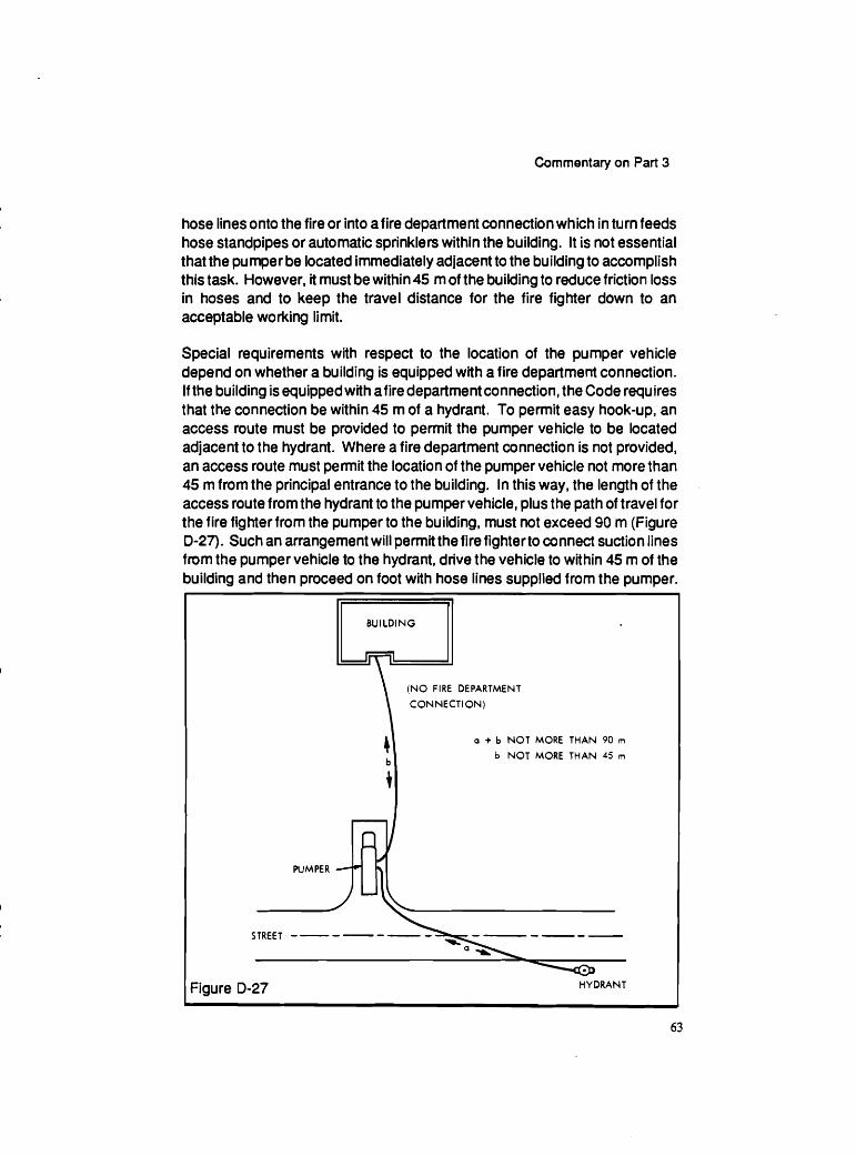
Commentary on Part 3
hose lines onto the fire or into afire department connection which in turn feeds hose standpipes or automatic sprinklers within the building. It is not essential that the pumper be located immediately adjacent to the building to accomplish this task. However, it must be within 45 m of the building to reduce friction loss in hoses and to keep the travel distance for the fire fighter down to an acceptable working limit.
Special requirements with respect to the location of the pumper vehicle depend on whether a building is equipped with a fire department connection. If the building is equipped with afire department connection, the Code requires that the connection be within 45 m of a hydrant. To permit easy hook-up, an access route must be provided to permit the pumper vehicle to be located adjacent to the hydrant. Where a fire department connection is not provided, an access route must permit the location of the pumper vehicle not more than 45 m from the principal entrance to the building. In this way, the length of the access route from the hydrant to the pumper vehicle, plus the path of travel for the fire fighter from the pumper to the building, must not exceed 90 m (Figure 0-27). Such an arrangement will permit the fire fighter to connect suction lines from the pumper vehicle to the hydrant, drive the vehicle to within 45 m of the building and then proceed on foot with hose lines supplied from the pumper.
(NO FIRE DEPARTMENT
CONNECTION)
a + b NOT MORE THAN 90 rn
b NOT MORE THAN 45 rn
PUMPER --
STREET ------ - ------ -\
Figure D-27 HYDRANT
Cop
yrig
ht ©
NR
C 1
941
- 201
9 W
orld
Rig
hts
Res
erve
d ©
CN
RC
194
1-20
19 D
roits
rése
rvés
pou
r tou
s pa
ys
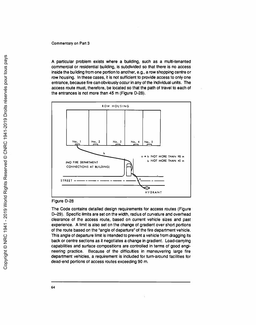
Commentary on Part 3
A particular problem exists where a building, such as a multi-tenanted commercial or residential building, is subdivided so that there is no access inside the building from one portion to another, e.g., a row shopping centre or row housing. In these cases, it is not sufficient to provide access to only one entrance, because fire can obviously occur in any of the individual units. The access mute must, therefore, be located so that the path of travel to each of the entrances is not more than 45 m (Figure 0-28).
Figure 0-28
ROW H O U S I N G
The Code contains detailed design requirements for access routes (Figure D-29). Specific limits are set on the width, radius of curvature and overhead clearance of the access route, based on current vehicle sizes and past experience. A limit is also set on the change of gradient over short portions of the route based on the "angle of departure" of the fire department vehicle. This angle of departure limit is intended to prevent a vehicle from dragging its back or centre sections as it negotiates a change in gradient. Load-carrying capabilities and surface compositions are controlled in terms of good engi- neering practice. Because of the difficulties in maneuvering large fire department vehicles, a requirement is included for turn-around facilities for dead-end portions of access routes exceeding 90 m.
No. 1
a + b NOT MORE THAN 90 rn
(NO FIRE DEPARTMENT b NOT MORE THAN 45 rn
CONNECTIONS AT BUILDING)
STREET ----- --- - -
H Y D R A N T
No. 2 No. 3 N o . 4 n
N o . 5 n
Cop
yrig
ht ©
NR
C 1
941
- 201
9 W
orld
Rig
hts
Res
erve
d ©
CN
RC
194
1-20
19 D
roits
rése
rvés
pou
r tou
s pa
ys

Commentary on Part 3
BUILDING REQUIRED TO
FACE 2 STREETS
6 rn
3 m MIN. IF
I N BUILDING
I---- STREET - - - - - -
Figure 0-29
Fire Suppression Systems
A major concern in fighting a building fire is an adequate supply of water at the site. The water supply requirements for fire protection installations depend on the requirements of any sprinkler installations and also on the number of hose streams that may be needed at a fire, and the length of time the hose streams would be used. Both these factors are largely influenced by the conditions at the building. The quantity and pressure of water for the protection of both the interior and exterior of the building must be ascertained before the water supply is decided upon. The selection of water supplies for each installation
Cop
yrig
ht ©
NR
C 1
941
- 201
9 W
orld
Rig
hts
Res
erve
d ©
CN
RC
194
1-20
19 D
roits
rése
rvés
pou
r tou
s pa
ys

Commentary on Part 3
should be determined in co-operation with the authority having jurisdiction, and the fire department. If water supplies are not available from a public waterworks system with sufficient pressure and discharge capacity, then the building owner would need to make other provisions, including automatic fire pumps, pressure tanks, gravity tanks or fire pumps operated by remote control devices at each hose station.
It is assumed that fires in small buildings can be fought from hoses attached to external hydrants or pumper vehicles. When a building exceeds three storeysor 14 m in height, an internal standpipe system isconsidered essential. For a building three storeys or less in building height, where the building area exceeds specified limits (which depend on the major occupancy classification) the Code requires a standpipe system, unless the building is sprinklered.
The Code references NFPA-14, "Installation of Standpipe and Hose Systems'' for specific details for the design, construction, installation, and testing of standpipe and hose systems. The Code perniits the water supply to be limited to 30 Us rather than the higher values that would be required for some larger buildings if designed in strict conformance with the NFPA Standard. In a sprinklered building with standpipe system risers, the NFPA Standard permits the same riser to be used for both the standpipe and hose system and the sprinkler system, provided certain conditions are met.
If a building or part of a building is required to be sprinklered, the sprinkler system must be designed, constructed, installed and tested in conformance with NFPA 13, "Installation of Sprinkler Systems." An exception to this is permitted if fewer than nine sprir~klers are required to give local protection to a specific area, in which case the sprinklers may be supplied from an adequate domestic water service. These sprinklers must have separate shut-off valves where the water supply piping serves other equipment. Typical areasforwhich local sprinkler protection is required in an unsprinklered building include garbage and laundry chutes, restaurants and licensed beverage establish- ments in high buildings, and some special service areas.
High Buildings
The time required for complete evacuation of a high building can exceed that which is necessary for the safe egress of the occupants. Studies of the 'stack' or 'chimney' effect in heated buildings in winter and observations of smoke movement in fires have shown that other measures in the Code may not
Cop
yrig
ht ©
NR
C 1
941
- 201
9 W
orld
Rig
hts
Res
erve
d ©
CN
RC
194
1-20
19 D
roits
rése
rvés
pou
r tou
s pa
ys

Commentary on Part 3
prevent the movement of smoke through elevator, stair and other vertical shafts to the upper storeys of a high building. Occupants of a high building, particularly those on upper storeys, may be faced with severe smoke condi- tions from a fire in storeys below them before their own evacuation is possible. Because of this and other considerations peculiar to high buildings, Subsec- tion 3.2.6. has been developed to provide additional safety features for these buildings.
The objectives of this Subsection are: (a) to provide for the safetyof building occupants, either by maintain-
ing the tenability of st he occupied floor spaces during the period of a fire emergency, or by making it possible for occupants to move to a place of safety;
(b) to maintain-tenable conditions in exit stairs leading from floor spaces to the outdoors, in which occupants may remain; and
(c) to maintain tenable conditions in elevators that can be used to transport fire fighters and their equipment from the street floor to the floor immediately below the fire floor.
It is assumed that the fire fighters will use one of the protected stairshafts to walk-up to the fire floor from the floor below.
The first objective may be met by evacuating all occupants to the outdoors in about seven to ten minutes, by moving occupants to safe areas within the building in from three to five minutes, or by maintaining the tenability of all floor areas except the fire floor and the floor immediately above it. The require- ments in the Code covering exit widths and travel distances to exits enable occupants of a floor on which a fire occurs to leave that floor within one or two minutes, provided their escape route is not cut off by the fire.
The objectives of the measures are to maintain certain spaces substantially smoke free for a significant period of time during a fire emergency, and hence some criterion of tenability is called for. The criterion for long term tenability is that a space does not include more than one percent by volume of contaminated air from the fire floor. This criterion is based on visibility and carbon monoxide concentration.
Subsection 3.2.6., "Additional Requirements for High Buildings," applies to all buildings more than 36 m in height, measured from grade to the floor level of the top storey, classified as Group A, D, E or F major occupancy. In the case
Cop
yrig
ht ©
NR
C 1
941
- 201
9 W
orld
Rig
hts
Res
erve
d ©
CN
RC
194
1-20
19 D
roits
rése
rvés
pou
r tou
s pa
ys

Commentary on Part 3
of Group B or C major occupancy buildings, the requirements apply to all buildings more than 18 m in height, measured between grade and the floor level of the top storey. If the building is designed for patients in bed on the fourth or higherfloors, the requirements also apply even where the building is less than 18 m high. This is due to the inherently long evacuation times for these buildings. Buildings classified as Group A, D, E or F ma,jor occupancy, in which the distance between grade and the floor level oft he top storey is more than 18 m, must also be classed as high buildings if the total number of people from all floors served by the exit stairs exceeds 300 persons per unit of exit width. This again is based on the fact that there will be slow evacuation due to crowding on stairs.
Suppose, for example, the ten-storey office building in Figure 0-30 has 240 persons on each floor, and two exit stairs are provided, each with two units of exit width (an exit stair width based on 60 persons per unit of exit width, permitted under Section 3.4 for Group D, business and personal services occupancies). The total number of persons using the exit stairs that connect the sixth and fifth floors would be those from the top five floors (i.e., 1200 persons). If the total units of exit width is four, this would mean a cumulative occupant load of 120014, or 300 persons per unit of exit width. This is the maximum load permitted if the building is not to be within the scope of Subsection3.2.6. Unless additional unitsof exit width are provided in the stairs connecting floors one to five, the building would be considered a high building, even though it is less than 36 m high. The stairways connecting the first and second floors in Figure 0-30 have a total occupant load of 21 60, so that a total of 7.2 units of exit width would have to be provided in order not to exceed 300 persons per unit of exit width. Similarly, 6.4 units would have to be provided between the second and third floors, 5.6 units between the third and fourth floors, and 4.8 units between the fourth and fifth floors. In practice, these widths would be rounded up to the next half or full unit because only full or half units are considered in the Code.
Subsection 3.2.6. establishes limits on smoke migration into different areas of a building, includingfloorareas, exit stairways and elevator shafts, in the event of a fire, and also contains a number of general requirements that apply to all high buildings. Acceptable methods to achieve these limits are described in Chapter 3 of the Supplement to the National Building Code of Canada 1985. This chapter describes a number of met hods for achieving the desired level of safety, depending on the height and occupancy of the building and the design that an owner wishes to use. C
opyr
ight
© N
RC
194
1 - 2
019
Wor
ld R
ight
s R
eser
ved
© C
NR
C 1
941-
2019
Dro
its ré
serv
és p
our t
ous
pays

Commentary on Part 3
ASSUME 2 EXITS, EQUAL WIDTH I
CUMU UTIVE
No. OF
PERSONS
USING
EACH
EXIT
STAIR
c. I 240 PERSONS
Figure 0-30
Although specific requirements for high buildings depend on the method of smoke control used, a nurr~ber of general requirements apply to all high buildings. These measures include the following:
(a) control of elevators by keyed switches, (b) a fire fighters' elevator, (c) smoke venting to aid fire fighting from each floor area to outdoors
by smoke shafts, windows or the building exhaust system, (d) sprinklering certain essential areas, (e) additional smoke development and flame-spread limits on sur-
face materials, (1) a central alarm and control facility to coordinate and direct
procedures for life safety, (g) two way voice communication from each floor to the central alarm
and control facility in buildings over 36 m high, and (h) fire protection of electrical feeders for emergency equipment.
Cop
yrig
ht ©
NR
C 1
941
- 201
9 W
orld
Rig
hts
Res
erve
d ©
CN
RC
194
1-20
19 D
roits
rése
rvés
pou
r tou
s pa
ys

Commentary on Part 3
Interconnected Floor Space
A recent trend in building design has been the increasing use of interior spaces that connect a number of floors of a building. In classical buildings this is an atrium, however, for Code purposes, the term interconnected floor space has been used. An interconnected floor space is one where two or more levels of a building are open to each other and the opening is not enclosed in the usual manner. Clearly then, interconnected floor space is also found in buildings whose floor areas are connected by open stairs and ramps, escalators and conveyors.
The Code generally requires that all openings through fire separations be protected by proper closures. The exceptions to this rule are found in Subsection 3.2.8. This Subsection starts with a general rule that any time a floor assembly does not terminate at an outside wall, a firewall or a vertical shaft, then that floor assembly must terminate at a vertical fire separation. The remainder of the Subsection deals with situations where this vertical fire separation is not provided.
A vertical fire separation is not practicable in a theatre space which has audience balconies. A vertical fire separation is also not required in an arena building up to two storeys high. This is to permit viewing galleries in, for example, curling rinks. The Code also permits the exclusion of the vertical fire separation where a space is not considered a storey in calculating building height, provided the mezzanine area is not more than 500 m2, and does not contain a Group B major occupancy.
Any open mezzanine up to 40 percent of the floor area is permitted in a building before it must be considered a storey. If it has visual obstructions then it can occupy no more than 10 percent of the floor area. Any mezzanine level above the first, however, must be considered a storey. If a mezzanine meets any of these conditions, then no vertical separation is needed as long as it is not more than 500 m2, and does not contain a Group B major occupancy.
The Code does not require additional protection for ramp openings in parking garages. Openings for conveyors for industrial processes are also permitted in the Code, but only when precautions are taken to offset the hazard, e.g., sprinklers or specially designed fire doors. When escalators extend through a number of storeys in the building, they must be protected to offset the breaching of the horizontal fire separations as follows: the size of the floor opening must be limited, the opening must be protected by a specially designed sprinkler system or rolling shutter, and the entire building must be
Cop
yrig
ht ©
NR
C 1
941
- 201
9 W
orld
Rig
hts
Res
erve
d ©
CN
RC
194
1-20
19 D
roits
rése
rvés
pou
r tou
s pa
ys

Commentary on Part 3
sprinklered. If these conditions are met, then no additional protection need be provided. Escalators, stairs and moving walkways that go up or down only one storey need not be protected in Groups A (Divisions 1 and 2), D,' E, or F (Division 3) major occupancy buildings. This exception is to permit architec- tural stairways and escalators on the first floor of a building to connect with one floor either above or below.
If openings between floors do not fall into one of the categories previously mentioned, and do not terminate at avertical fire separation or an exteriorwall, then the specific and detailed requirements in Subsection 3.2.8. must be applied.
Interconnected floor space presents two major problems: the potential for rapid and progressive development of an uncontrolled fire between levels of the structure, and the lack of a barrier to prevent smoke from contaminating simultaneously all open levels of the building.
These problems could result in: (a) the inability of persons to leave the building before being over-
come by heat or smoke, since all levels will have to exit simulta- neously,
(b) the exposure of major building structural components to a prolonged fire condition, since there are no barriers to resist fire spread, and
(c) the impedance to effective fire fighting actions, since fire fighters traditionally use the floor beneath the fire floor as a staging area.
Unless additional safety precautions are incorporated in the design, a building containing an interconnected floor space will fall far short of the fire safety goals of the Code. Where a building contains an interconnected floor space, that building must be of noncombustible construction or heavy timber con- struction, depending on its size.
Vestibules are necessary for exits opening into an interconnected floor space to provide protection for the exit with fire rated construction. These vestibules must provide a smoke free exit stair and must be located within 45 m travel distance from any point within the interconnected floor space. Vestibules are also required to protect elevator doors where the elevator serves floors above the interconnected floor space. This is to ensure that smoke produced in an interconnected floor space will not progress up elevator shafts into the floors
Cop
yrig
ht ©
NR
C 1
941
- 201
9 W
orld
Rig
hts
Res
erve
d ©
CN
RC
194
1-20
19 D
roits
rése
rvés
pou
r tou
s pa
ys

Commentary on Part 3
above. The Code requires that hose stations be provided in vestibules which serve exit stairs.
One method of occupant protection in an interconnected floor space is to provide exits that are cumulative. In other words, all occupants on all floors must be able to enterthe stairs simultaneously. As an alternative to cumu tative exiting, the designer can provide 0.3 m2 of treads and landings per person in the exit stairs. This permits a holding area that all occupants can enter but where they must wait to move to the outside. A designer can also provide a 'protected floor space' of 0.5 m2 per person. In no case must an occupant have to enter or re-enter the interconnected floor space before leaving the building.
A protected floor space is a space separated from the interconnected floor space by fire rated construction so that occupants of the interconnected floor space can enter the protected floor space and use it as a waiting area before evacuation by stairs serving this space (Figure 0-31). A condition of using a protected floor space is that the occupant does not have to re-enter the interconnected floor space in order to get to the outside of the building.
SEPARATION
RATING FOR
PROTECTED FLOOR SPACE
Figure 0-31
Cop
yrig
ht ©
NR
C 1
941
- 201
9 W
orld
Rig
hts
Res
erve
d ©
CN
RC
194
1-20
19 D
roits
rése
rvés
pou
r tou
s pa
ys

Commentary on Part 3
Sprinklers are required throughout a building containing an interconnected floor space, not only in .the open space but in all other portions of the building. The Code, by reference to NFPA 13, "Installation of Sprinkler Systems," requires that close-spaced sprinklers and baffles be provided around all but the largest of openings, in a manner similar to that required for escalator protection. The baffles are intended to restrain the products of combustion from spilling directly into the open space, and thereby provide a reservoir for these products below the ceiling level; the build-up of heat ensures a faster operation of the sprinklers. All sprinkler systems must be fully supervised and must provide a signal to the fire department.
Fire alarm systems must be provided in all buildings which contain an interconnected floor space, and smoke detectors must be located around the opening in the baffled areas. The baffles and their function as a reservoir for the products of combustion helps to ensure that any smoke will migrate into the vicinity of a smoke detector. For additional reliability, the Code requires that the fire alarm system have aconnection to notify the fire department when an alarm is actuated.
To assist in clearing smoke from the open space, mechanical exhaust is required for an interconnected floor space at the rate of four air changes per hour, based on the total volume of the interconnected floor space. This smoke removal system is controlled by a manual switch located near the street entrance. This is a manual system and not an automatic smoke control system as required for high rise buildings.
Sprinklers located more than 8 m above the floor of an interconnected floor space may not respond quickly enough to a fire. As a result, the Code limits the quantity of combustible materials in these higher open spaces to 16 g for each cubic metre of volume of the interconnected floor space.
Although there are many unknown problems in buildings containing intercon- nected floor space, the Code requirements for these buildings are expected to give a level of protection similar to that which would be achieved if Floor-to- floor fire separations were provided.
Cop
yrig
ht ©
NR
C 1
941
- 201
9 W
orld
Rig
hts
Res
erve
d ©
CN
RC
194
1-20
19 D
roits
rése
rvés
pou
r tou
s pa
ys

Commentary on Part 3
CHAPTER 5
SAFETY WITHIN FLOOR AREAS
General
Section 3.3 contains requirements that provide for the safety of occupants within floor areas. The term floorarea applies to all of the space on the storey bounded by the exterior walls and any firewalls, but does not include the space occupied by exit stair shafts, elevator shafts or other vertical service shafts. In effect, it includes all of the space within a storey, including that occupied by interior walls, less the area occupied by vertical shafts that extend through the floor assembly of the storey. Floor areas include service rooms, but require- ments for these rooms are covered in Section 3.5 and not in Section 3.3.
The requirements in Section 3.3 depend upon the specific occupancy or use of the space and the safety provisions that are required as a result of that use. The requirements do not necessarily relate to major occupancy, a concept described previously. In addition to providing measures to control or isolate known fire hazards, this Section regulates other safety provisions for safe access to exits from the various occupancies.
Access to Exlts
Access to exit is a commonly misunderstood term; people often relate it only to corridors. It is that part of a means of egress within a floor area that provides access to an exit serving the floor area. Means of egress is a continuous path of travel provided by a doorway, corridor, exterior passageway, balcony, lobby, stair, ramp or other egress facility from any point in a building, floor area or contained open space to a public thoroughfare or other safe open space. The question of what constitutes a safe open space is often asked. Typically, this determination is specific to the design being considered and is based on an evaluation of such factors as the egress from the space, the construction and separation of the building and the presence of other hazards. For example, the roof of an adjacent open air parking deck may be considered a safe open space for egress from the second storey of a building, provided it is protected from fire exposure from the building and has access to a public thoroughfare.
Cop
yrig
ht ©
NR
C 1
941
- 201
9 W
orld
Rig
hts
Res
erve
d ©
CN
RC
194
1-20
19 D
roits
rése
rvés
pou
r tou
s pa
ys

Commentary on Part 3
Access to exit means a path of travel from any point on a floor area to an exit from that floor area (Figures E-1 and E-2). It does not mean only the corridors that lead to exits, although in many cases they form the most critical part of the access to exit, since all occupants must funnel through the corridor to reach the exit. Corridors that are not located within suites are subject to more demanding requirements than other parts of the access to exit.
Figure E-1
Figure E-2
A number of access to exit requirements depend upon whether a floor area is under one tenancy or is subdivided into separate tenancies. Where a floor area is divided into more than one tenancy or suite, specific requirements regulate the access to exit fromwithin the suite to the egress doorordoors from the suite, as well as the access to exit from the suite door or doors to the exits from the floor area. The required egress doors must open into a corridor or a passageway that permits a choice of two directions of travel to separate exits, unless the egress is an exit door at ground level (Figure E-1). A number of exceptions to this general rule, which permit the restricted use of dead-end corridors, will be discussed in relation to corridors. C
opyr
ight
© N
RC
194
1 - 2
019
Wor
ld R
ight
s R
eser
ved
© C
NR
C 1
941-
2019
Dro
its ré
serv
és p
our t
ous
pays

Commentary on Part 3
A room or suite of rooms occupied as a separate tenancy is required to have at least two egress doorways if the travel distance within the room or suite to a public corridor exceeds the area and travel distance limits established in the Code, if the occupant load is more than 60 persons, or if the room or suite contains a high hazard industrial occupancy. These doorways must be separated from each otherto the extent that if one should become inaccessible due to a fire in the room or suite, the other can still be used. It is difficult to be specific about the exact distance that would constitute an adequate separa- tion, since this would depend on the design of the suite. Obviously, the further apart these doors are, the better the chances are that the second door would be accessible in the event that a fire blocked the first door. The same egress requirements apply to a contained open space, such as an enclosed court- yard.
Throughout Section3.3, reference is made to the term suite. A series of rooms that constitute a suite must be in reasonably close proximity to each other, must have access to eachothereitherdirectly by meansof acommon doorway or indirectly by an interiorc~rridorwithin the suite, by avestibule or other similar arrangement. In many cases the Code permits a relaxation in requirements for fire separations between certain occupancies if such occupancies are located within the same suite. It also permits a relaxation of corridor requirements when the corridors are located within suites, as opposed to corridors that serve a number of suites.
Tenancy in the context of the term suite applies to both rental and ownership tenure. In a condominium, for example, dwelling units are considered separate suites, even though they are individually owned.
The term suite does not apply to rooms, such as service rooms, common laundry rooms and common recreational rooms that are not leased or under a separate tenure in the context of the Code. Similarly, the term suite is not normally applied in the context of buildings such as schools and hospitals, since the entire building is under a single tenure. A rented room in a home for the aged could be considered a suite if the room was under a separate tenure. A hospital bedroom, on the other hand, is not considered to be under a separate tenure, since the patient has little control of that space, even though he pays the hospital a per diem rate for the privilege of using the hospital facilities, which include the sleeping areas. In a hospital, while there may be groups of rooms that act as a unit, such as a maternityward or an intensive care unit, they are not suites in the true sense, since they are not under separate management or control.
Cop
yrig
ht ©
NR
C 1
941
- 201
9 W
orld
Rig
hts
Res
erve
d ©
CN
RC
194
1-20
19 D
roits
rése
rvés
pou
r tou
s pa
ys

Commentary on Part 3
For certain requirements in the Code, the expression morn or suite is used (e.g;, travel distance). In such cases the requirement applies within rooms of suites as well as to the suite itself and to rooms that may be located outside the suite. In other places the expression suite, and rooms not located within a suite is used (e.g., for the installation of smoke and heat detectors). This expression means that the requirement applies to individual suites as defined, but not to each room within the suite. The rooms 'not within a suite' would include common laundry rooms, common recreational rooms and service rooms that are not considered tenant occupied space.
The Code specifies that suites otherthan in a business and personal services occupancy must be separated from each other by a fire separation having a specific fire-resistance rating. This separation will help to contain a fire to the suite of origin and prevent its spread to neighbouring suites. The occupants of the neighbouring suites will not be aware of a fire until they hear a fire alarm or smell the products of combustion. In certain non-residential occupancies the Code exempts noncombustible heating ducts from having fire dampers in the plane of a fire separation that they penetrate (Figure E-3).
CONTINUOUS NONCOMBUSTIBLE DUCT.
MELTING POINT NOT LESS THAN 760°C
SUITES SUITE " B "
SUITE " A "
WALL HAS REQUIRED
FIRE RESISTANCE
I I
Figure E-3
Corridors
As discussed previously, corridors other than those located within a suite are subject to more restrictive requirements than are other parts of the floor area, since the occupant does not have direct control over that part of the escape
Cop
yrig
ht ©
NR
C 1
941
- 201
9 W
orld
Rig
hts
Res
erve
d ©
CN
RC
194
1-20
19 D
roits
rése
rvés
pou
r tou
s pa
ys

Commentary on Part 3
route. These corridors include those that serve separately rented suites (public corridors), patients' bedrooms, classrooms, sleeping rooms (not within suites) or other corridors used by the public. These conidors are designed so that once the occupants of an adjacent space enter the corridor, they are in an area of relative safety, which will enable them to reach an exit facility in the event of a fire.
The expression corridors used by the public should not be confused with public corridors. Public corridors are special; they provide access to exits from a multi-tenanted floor area such as in an apartment building or a hotel. Corridors used by the public do not necessarily serve multiple tenants and normally occur in institutional, assembly, and business and personal services occupancies. The Code also regulates corridors serving patients' bed rooms or classrooms; these are treated as special corridors and are protected ac- cordingly. Typically, these special corridors must be separated from adjacent spaces and their flame-spread requirements are more restrictive than those for the occupancies they serve. These corridors must also have minimum lighting levels, for normal usage as well as emergency lighting.
Dead-end corridors do not provide the degree of life safety offered by those without dead ends. For this reason, their use is restricted in the Code unless a second means of egress is provided, although in certain designs they may be necessary for the efficient utilization of space. The limitations on dead-end corridors are specified in relation to the occupancy and occupant load served by the corridor, and the existence of an alternative means of egress from the rooms or suites served.
In assembly, institutional, mercantile or high hazard industrial occupancies, dead-end corridors are not permitted unless there is a separate means of egress from the space served by the dead-end. For residential occupancies, a dead-end is permitted, provided it does not exceed 6 m from *the end of the corridorto the nearest exit, or serve more than four suites, and that occ~~pants need not pass more than two suite entrance doors to reach the nearest exit (Figure E-4).
SUITE 1 SUITE 2
6 rn MAX
SUITE 3
I I Figure E-4
Cop
yrig
ht ©
NR
C 1
941
- 201
9 W
orld
Rig
hts
Res
erve
d ©
CN
RC
194
1-20
19 D
roits
rése
rvés
pou
r tou
s pa
ys

Commentary on Part 3
In business and personal services occupancies, the requirements are more permissive; dead-end public corridors can be 9 m in length from the most remote point of the dead end to the nearest exit and can serve an occupant load of up to 30 persons. The persons using the corridor, however, must not be required to pass more than two doors on the way to an exit (Figure E-5). Sirr~ilar requirements apply to medium and low hazard industrial occupancies.
OCCUPANT LOAD OF
SUITE 1 + SUITE 2 + SUITE 1
SUITE 3 NOT GREATER
THAN 30 9 m MAX
SUITE 2 SUITE 3
Figure E-5
Capacity of Access to Exit
Although minimum widths are given for doorways and certain corridors used in an access to exit, they are subject to overriding requirements which regulate the width on the basis of the occupant load served by these facilities, if these are more stringent. As a general rule, there must be at least one 550 mm unit of exit width for every 90 persons served by the access to exit. In the case of access to exits serving infirm persons, this number is reduced to 30 persons. Where stairs, ramps or escalators are incorporated in an access to exit (other than for infirm persons), the number of persons per unit of exit width must be reduced to 60 because of the restriction to flow caused by these facilities.
The calculation of units of exit width is covered in the chapter on exits. They are calculated only in multiples of 550 mm units (the assumed width needed to accommodate an average person). Credit can be given, however, for half units where the width of a facility exceeds the width of full units by at least 300 mm. The occupant load for which the required access to exit width is calculated has been discussed previously.
The width required for the access to exit can be determined in a straightforward manner where the egress is out of a single large room or suite and where the egress flow is predictable. In more complicated arrangements, where there
Cop
yrig
ht ©
NR
C 1
941
- 201
9 W
orld
Rig
hts
Res
erve
d ©
CN
RC
194
1-20
19 D
roits
rése
rvés
pou
r tou
s pa
ys

Commentary on Part 3
may be multiple stairs with corresponding multiple egress paths, it is not always simple to determine the population that would use a particular access to exit route. Judgment must be exercised to determine occupant loads served by a partiarlar route. Figure E-1 depicts a simple arrangement of suites with a central conidor and a stair at each end. The corridor should be designed on the basis of the population that would be expected to use the facility in an emergency.
In Figure E-1 the width of the comdor would be determined by assuming that half the ocarpant load will use one exit and half the other, assuming each exit provides at least half the required units of exit width. Figure E-6 shows how the occupants may be assumed to use access to exit routes in a more complicated building. The flow assumes that the occupants will move to the nearest exit.
STAIR No. 3 STAIR No. 4
A 0 C D E F
dVk
I I I - I I G H I J K L
STAIR No. 1 N STAIR No. 2
0
r
P Q X Y
I I i
I I
S T U Z A -A I , 0-0
Figure E-6
Cop
yrig
ht ©
NR
C 1
941
- 201
9 W
orld
Rig
hts
Res
erve
d ©
CN
RC
194
1-20
19 D
roits
rése
rvés
pou
r tou
s pa
ys

Commentary on Part 3
Assembly Occupancles
Most of the Subsection on assembly occupancies is concerned with means of egress from various seating arrangements in such occupancies. In certain assembly occupancies the seats are located on either side of an aisle (Figure E-7). An alternative to this arrangement is continental seating, where long rows without aisles discharge directly into doors sewing not more than three
I I CROSS AISLE I
STAGE
I 1
Figure E-7
rows (Figure E-8). Both arrange- ments are acceptable in the Code.
The Code contains specific require- ments relating todead-end aisles and the number of seats to an aisle, for the arrangements in Figures E-7 and E-8. The width of aisles is developed on the basis of distance from the row to an exit, and increases by 25 mmfor every metre of length toward an exit. The minimum width of aisle should obviously be at the point in the aisle farthest from the exit doorway.
The arrangement of rows of fixed seats and its effect on emergency egress is often questioned. The Code intends that if seat bottoms are fixed, then the clear passage of 400 mm is measured from the edge of the seat bottom to the back of the seat in front. If the seat bottoms retract automati- cally, then the clear passage is measured from the furthest projec- tion, as is shown in Figure E-9.
Cop
yrig
ht ©
NR
C 1
941
- 201
9 W
orld
Rig
hts
Res
erve
d ©
CN
RC
194
1-20
19 D
roits
rése
rvés
pou
r tou
s pa
ys

Commentary on Part 3
SEATS WlTH FIXED BOT
SEATS WlTH RETRACTABLE BOTTOMS
Figure E-9
lnstltutlonal Occupancies
The Code requirements in this Subsection are primarily directed toward health care occupancies. Such occupancies require additional fire safety because many occupants cannot take effective action in the event of an emergency. Fire separations are required to separate sleeping rooms except when two or more intercommunicating rooms have an occupant load of not more than five, in which case the walls between the rooms need not be fire separations. In a fully sprinkle red building, the fire separations between sleeping rooms are not required to have a fire-resistance rating, but in unsprinklered buildings, they must have a specified fire-resistance rating. In addition, the Code requires corridors to be separated fmm adjacent moms, but exempts doors serving patients' rooms from the requirements for positive latching devices if the doors are equipped with roller latches. Further, doors between patients' rooms and
Cop
yrig
ht ©
NR
C 1
941
- 201
9 W
orld
Rig
hts
Res
erve
d ©
CN
RC
194
1-20
19 D
roits
rése
rvés
pou
r tou
s pa
ys

Commentary on Part 3
corridors need not be equipped with self closing devices if the building conforms to Sentence 3.3.3.6.(2), i.e., a sprinklered building divided into fire compartments, each with an area not more than 1000 m2 .
To permit the horizontal movement of patientsto a relatively safe location, floor areas containing patients in bed or infirm persons in hospitals and nursing homes must be divided into two or more zones, separated from each other by fire separations. These zones must be large enough to contain both their own occupants and the occupants of the largest adjacent zone, and the travel distance to a zone door must not exceed 30 m in an unsprinklered building and 45 m in a sprinklered building. The purpose of these zones is to permit patients to be moved horizontally away from afire, thus avoiding the difficulty of moving them down stairs (Figure E-10).
/FIRE SEPARATION
EXIT EXIT
- I - -
ZONE No. 1 ZONE No. 2
I I
Figure E-10
Resldent la1 Occupancles
This Subsection is concerned primarily with egress from suites and dwelling units in residential occupancies. The Code permits a single exit if it is an exterior door at or near ground level, and limits the travel distance within the suite to one storey unless the upper level is served by a balcony within 6 m of ground level.
A multi-storey dwelling unit in an apartment building is required to have exit or egress doors located at the upper and lower floor levels. An exception to this general rule occurs when the upper and lower floor levels in a dwelling unit are provided with an egress door within 1.5 m of the upper and lower floors (Figure E-11). As another alternative to the egress door from the upper or lower levels, an internal stairway leading to a public access to exit is considered adequate provided :
Cop
yrig
ht ©
NR
C 1
941
- 201
9 W
orld
Rig
hts
Res
erve
d ©
CN
RC
194
1-20
19 D
roits
rése
rvés
pou
r tou
s pa
ys
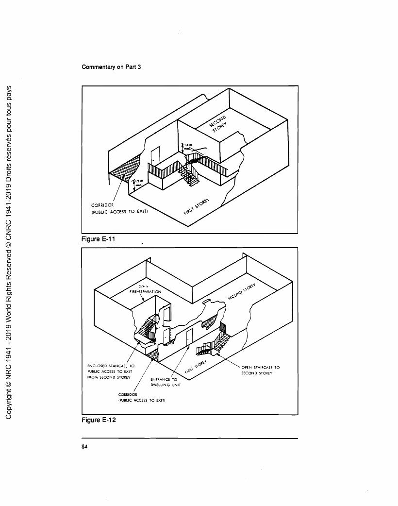
Commentary on Part 3
Figure E-1 1
ENCLOSED STAIRCA OPEN STAIRCASE TO PUBLIC ACCESS TO SECOND STOREY
FROM SECOND ST0
DWELLING UNIT
Figure E-12 Cop
yrig
ht ©
NR
C 1
941
- 201
9 W
orld
Rig
hts
Res
erve
d ©
CN
RC
194
1-20
19 D
roits
rése
rvés
pou
r tou
s pa
ys

Commentary on Part 3
it has no direct access to any other floor in the dwelling unit, and it is separated from the remainder of the dwelling unit by a h fire
separation (Figure E-12).
Business and Personal Setvices Occupancies
Due to the less hazardous nature of business and personal services occupan- cies, the Code imposes few additional major restrictions on their use. The rules for dead-end corridors are somewhat less restrictive than in other occupancies.
Mercantile Occupancies
In this occupancy the Code has added a requirement for spandrel or canopy protection for storeys above or below the mercantile occupancy, due to the high fire loads normally occurring in such occupancies (Figure E-13). Added requirements prohibit the use of turnstiles or posts in a meansof egress unless an alternative unobstructed path of travel is available.
I 1 i
2nd FLOOR SPANDREL 2nd FLOOR
I
CANOPY
I / 1st FLOOR
' i 1st FLOOR 1 m
Figure E-13
Industrial Occupancies
The Code imposes additional restrictions on industrial occupancies due to their more hazardous nature. These restrictions relate to fire separations, fire protection systems and protection of hazardous equipment or processes. Due to the possibility of gas or carbon monoxide movement, the Code requires vestibule protection for openings between storage and repair garages and other occupancies. Spandrel or canopy protection is also required for storeys above and below a Group F, Division 1 or 2 occupancy.
Cop
yrig
ht ©
NR
C 1
941
- 201
9 W
orld
Rig
hts
Res
erve
d ©
CN
RC
194
1-20
19 D
roits
rése
rvés
pou
r tou
s pa
ys
Commentary on Part 3
CHAPTER 6
EXITS
General
As discussed previously, egress from a building is divided into two compo- nents: the path of travel to reach an exit (access to exit), and the path of travel through the exit. In the previous chapter the various components involved in reaching an exit were discussed. This chapter considers aspects of the exit itself.
An exit is that part of the means of egress that leadsf rom the floor area it serves to a safe location. Obviously, a door opening directly to the outside at ground level fulfills this requirement. The Code recognizes a number of other exit facilities: interior and exterior passageways and ramps, fire escapes and horizontal exits.
The exact location where an exit starts and finishes is usually easy to determine. However, in grandstands, arenas, industrial process buildings and similar situations, these locations are not easily discernible, and judgment must be exercised in applying the requirement.
The difference between an interior exit passageway (or the horizontal projec- tion of an exit shaft) and a public corridor is often questioned. The difference is that an exit passageway must be designed as an exit. The fire separation between it and the floor area must be rated as an exit. There can be no openings in this fire separation except for exit doors, standpipes and smoke control systems. Certain rooms are not permitted to open directly into an exit. Doors opening into an exit passageway must open in the direction of the passageway and thus, forthe most part, must be recessed to avoid obstructing the exit. An exit passageway is subject to substantially more restrictive requirements than a public corridor, due to its role as an exit. An exit passageway would normally be unidirectional, whereas a public corridor must allow for movement in two directions. An exit passageway may not contain an occupancy, whereas a public corridor may. Flame-spread ratings are more restrictive for exit passageways than for public corridors.
Cop
yrig
ht ©
NR
C 1
941
- 201
9 W
orld
Rig
hts
Res
erve
d ©
CN
RC
194
1-20
19 D
roits
rése
rvés
pou
r tou
s pa
ys
Commentary on Part 3
Wldth of Exlts
One of the first items to be taken into account in determining the width of exits is the occupant load of the floor area. This concept was discussed in previous chapters; for the purposes of this chapter, it is assumed that the occupant load of the lloor area has been determined.
To determine the relationship between the occupant load and the width of exits required, the Code uses the concept of units of exit width, each 550 mm wide. Each unit of exit width is assumed to accommodate:
90 persons, in the case of exterior exit doors, 60 personsfor all other exit facilities, except for residential and institutional buildings, and 30 persons for all ex% facilities for residential or institutional buildings.
The width of exits is calculated by dividing the occ~~pant load for the floor area by the number of people per unit of exit width. The required units of exit width are not cumulative from floor to floor (i.e. the width of stair does not increase as one proceeds down the stair). Exceptions to this general rule are where exits from more than one floor converge, and where the exit sewes an interconnected floor space. To determine the number of units provided, each exit is examined in sequence by using the following expression:
Units of exit width = width of exit facility in mm/550
If the remainder is less than 300 mm, the Code gives no additional contribu- tion to flow of people. If the remainder is at least 300 mm, this is considered to contribute an additional l/2 unit of exit width.
The concept of dividing the exit width by units of exit width to get the number of units is applied to each individual exit facility in turn and not to the total width from a floor area. For example, a floor area sewed by two stairs, each 1250 mm wide, is assumed to be provided with 1250 mm/(550 mrn/unit) = 2 units plus 150 mm, i.e., two units per stair. The floor area is sewed by four units of exit width. The total stair width is not added together to obtain 2500 mm and the floor area assumed to be provided with 4.5 units of exit width.
Number of Exits and Travel Dlstance to Them
Basically, every floor area must be sewed by at least two exits. One exception to this rule allows single exits for small suites in one-and two-storey buildings where the occupant load does not exceed 60 persons, the travel distance is
Cop
yrig
ht ©
NR
C 1
941
- 201
9 W
orld
Rig
hts
Res
erve
d ©
CN
RC
194
1-20
19 D
roits
rése
rvés
pou
r tou
s pa
ys

Commentary on Part 3
minimal and the floor area does not contain a high hazard industrial occu- pancy. Dwelling units constitute the other major exception.
One of the limiting factors in determining the number of exits is the travel distance to an exit. Travel distance is the distance an occupant must travel to reach an exit. Limits on the travel distance to the nearest exit are governed by occupancy. The maximum travel distances permitted in the Code are:
60 m for public corridors complying with Clauses 3.4.2.3.(3)(a) to (d), 45 m, in the case of sprinklered floor areas, except for high hazard industrial occupancies (Group F, Division 1 ) , 40 m, in the case of Group D, business and personal services occupan- cies, and 30 m for all other situations.
Limiting travel distance to an exit is one way to reduce the hazard to the occupant. The measurement of travel distance is, therefore, important in the Code context. For an open floor area that serves a single tenant, the travel distance is measured from any point on the floor area to the nearest exit door (Figure F-1 ). If, however, the room or suite is separated from the remainder of a floor area by 3/4 h fire separations, the travel distance can be measured from the suite door to the exit (Figure F-2). If the conidor provided does not have at least a 3/4 h fire separation between it and the adjacent spaces, the travel distance is measured from the most remote point in the adjacent space through the corridor to the exit (Figure F-3).
Cop
yrig
ht ©
NR
C 1
941
- 201
9 W
orld
Rig
hts
Res
erve
d ©
CN
RC
194
1-20
19 D
roits
rése
rvés
pou
r tou
s pa
ys
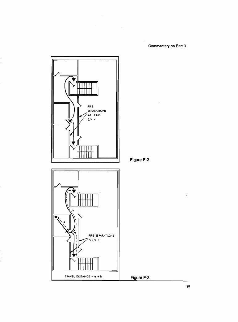
Commentary on Part 3
SEPARATIONS
Figure F-2
FIRE SEPARATIONS
Cop
yrig
ht ©
NR
C 1
941
- 201
9 W
orld
Rig
hts
Res
erve
d ©
CN
RC
194
1-20
19 D
roits
rése
rvés
pou
r tou
s pa
ys

Commentary on Part 3
Dlstance between Exits
As discussed previously in relation to doorways from suites, the greater the distance between exits the greater the possibility that one will be available in an emergency. The Code assigns a minimum distance between exits of half the diagonal dimension of an open floor area or 9 m in floor areas served by a public conidor, whichever is greater (Figure F-4). Where a floor area is divided by a fire separation and occupants must pass through the fire separation to travel from one exit to the other, then the minimum distance does not apply.
AT LEAST DL?
PLAN VIEW PLAN VIEW
PLAN VlEW
Figure F-4
Cop
yrig
ht ©
NR
C 1
941
- 201
9 W
orld
Rig
hts
Res
erve
d ©
CN
RC
194
1-20
19 D
roits
rése
rvés
pou
r tou
s pa
ys

Commentary on Part 3
Doorways
Exit doorways must have a headroom clearance not less than 2030 mm high (this can be reduced to 1980 mm to allow for closers) and a clear width of 790 mm, except that this clear width must be 1050 mm if the doorway serves areas where patients are in bed.
A door serving as an access to exit from a room or suite used by more than 60 persons or a high hazard industrial occupancy, and any door within a fire- separated corridor, must swing on avertical axis and must open in the direction of exit travel. Sliding doors are acceptable for exits leading directly outdoors at ground level, provided they will swing on a vertical axis when pressure is applied in the direction of exit travel.
Exit doors (except those serving dwelling units) must open in the direction of exit travel. The swing of exit doors is not permitted to reduce the effective width of a stair or landing to less than 750 mm, or the width of an exit passageway to less than its required width (Figure F-5). Exit doors themselves cannot reduce the required exit width by more than 50 mm for each unit of exit width provided by the door. This gives some latitude for door hardware.
AT LEAST 750
Figure F-5
Exit doors and doors from dwelling units must be openable from the inside without the use of keys, special devices or specialized knowledge of door- opening devices. In exit stairways in buildings more than six storeys in building height, doors must be openable from the stairway side so that a penon doesn't
Cop
yrig
ht ©
NR
C 1
941
- 201
9 W
orld
Rig
hts
Res
erve
d ©
CN
RC
194
1-20
19 D
roits
rése
rvés
pou
r tou
s pa
ys

Commentary on Part 3
have to travel up or down more than two storeys to reach an unlocked door to permit the person to re-enter a floor area to reach another exit in the event that the first stair becomes full of smoke.
Sepamtlon of Exlts
Exit facilities must be separated from the remainder of the building to prevent fire in an adjacent floor area from spreading into the exit and trapping occupants. The walls of an exit shaft must have the same fire-resistance rating as required for the floorthrough which it passes, with a minimum rating of h. Exit doorways, openings for standpipe and sprinkler piping, electrical wiring, noncombustibleconduit and piping that serve the exit, and openingsfor smoke control are the only openings permitted in exit separations.
Exit doors other than exterior doors are closures in a fire separation and, as such, must have the prescribed fire-protection rating and must be equipped with rated hardware and latches. As discussed in the section on closures (Protection of Openings, Chapter 3), certain exit doors must also provide protection against temperature rise on the unexposed face for specified time periods.
As discussed in the section on closures, the area of wired glass between a floor area and an exit cannot exceed 0.8 m2 except if the door or sidelight is located in an enclosed vestibule or corridor separated from the remainder of the floor by a Y4) h fire separation. These limits are to prevent possible exposure to the occupants, since wired glass will not act as a barrier to radiated heat.
The only exception to the continuous fire separation for exits is for a protected lobby. For some stairs special security measures are necessary and typical lobby designs do not create a hazardous condition. The Code permits occupants to leave exits and enter floor areas in such lobbies, provided they meet certain criteria. These criteria include the establishment of a maximum distance of 15 m through the lobby, limits on the adjacent occupancies, and separations between 'the lobby and adjacent spaces.
Flame Spread in Exits
The exit must remain tenable for as long as possible. Since fire fighters often use exit shafts to reach the fire floor long after the occupants have evacuated, flame spread on the surfaces within the exit shaft is restricted. Only 10 percent of wall and ceiling finishes in exits can have flame-spread ratings of up to 150;
Cop
yrig
ht ©
NR
C 1
941
- 201
9 W
orld
Rig
hts
Res
erve
d ©
CN
RC
194
1-20
19 D
roits
rése
rvés
pou
r tou
s pa
ys
Commentary on Part 3
the remainder of the finish materials are required to maintain a rating of 25. This permits minimal use of combustibles for finished appearance such as wood handrails and trim. In high buildings the Code also imposes restrictions on the flame-spread rating and smoke developed classification of floor covering materials.
Horizontal Exits
A horizontal exit is one that permits occupants to move from a f loor area in one building to a floor area of an adjacent building, either via a passageway or through a firewall. It does not conform to the basic premise that an exit takes an occupant from a floor area to a public thoroughfare or acceptable open space. The Code requires that the floor area on either side of a horizontal exit be large enough to accommodate the occupant load of both sides.
Doors in a horizontal exit must be designed to swing in both directions, or two doors must be provided, one opening in each direction. Since a horizontal exit does not lead directly to a public street or safe open space, they may constitute only part of the required exits from any floor area.
Fire Escapes
Fire escapes do not meet the same requirements as other exits but are permitted for use on existing buildings. They are limited to serving floor areas not more than two storeys above ground level for Group B occupancies and five storeys for other occupancies. It is difficult, if not impossible, to provide Codeconforming exits on a retrofit basis in some buildings. A fire escape is not required to be separated as is an exit; they need not have the same width as exits; access to a fire escape may be through a casement window; and fire escapes are not required to have the same standard of guards. For these and for environmental reasons (such as snow and ice accumulation) the Code accepts fire escapes only in limited circumstances.
Cop
yrig
ht ©
NR
C 1
941
- 201
9 W
orld
Rig
hts
Res
erve
d ©
CN
RC
194
1-20
19 D
roits
rése
rvés
pou
r tou
s pa
ys
Commentary on Part 3
CHAPTER 7
SERVICE FACILITIES
General
Section 3.5 contains specific requirements for service facilities. These include service rooms, containing equipment for serving the building, and horizontal and vertical service spaces, which are used to install wiring and piping from service rooms to the spaces served and also from room to room.
Most of the requirements of this Section relate to fire separations or other fire protection equipment needed to protect the service facilities. The equipment in the service rooms, especially fuel-fired equipment, has the potential to start fires, so the service rooms are isolated from the remainder of the building by fire separations. Many of the service spaces contain wiring and piping that form part of the emergency systems of the building and these must be separated from other parts of the building in which a fire could occur. These separations around service spaces also protect the remainder of the building from a fire that starts in or travels through a service space.
Section 3.5 does not contain specific requirements for the building services and service equipment but does reference other Parts of the N8C as well as CSA standard C22.1, "Canadian Electrical Code, Part I," for electrical wiring and equipment.
Sewlce Rooms
Because of the potential fire hazard in using fuel-fired equipment, this equipment must be installed in service rooms that are separated from the rest of the building by fire separations having a designated fire-resistance rating. For certain small buildings and single rooms or suites, the requirementsfor fire separations are waived if it can be shown by test results or other information that these are not necessary. The requirements for fire separations are also waived for fireplaces and rooftop appliances.
Some types of equipment are subject to explosions and service rooms containing this type of equipment (some boilers, transformers and refrigera- tion plants) must not be placed under exits.
Cop
yrig
ht ©
NR
C 1
941
- 201
9 W
orld
Rig
hts
Res
erve
d ©
CN
RC
194
1-20
19 D
roits
rése
rvés
pou
r tou
s pa
ys

Commentary on Part 3
Specific protection is required for rooms containing incinerators and for transformer vaults. Incinerators tend to have a wide range of garbage burnt in them, with little control over the contents; in addition, garbage tends to accumulate in the vicinity of manually fed incinerators. 'The necessity for a transformer vault is stated in provincial regulations or CSA C22.1, "Canadian Electrical Code, Part I." Vaults are required primarily where electrical equipment contains flammable or combustible liquids. They are generally not required for air-cooled equipment or for equipment containing non-combus- tible liquids.
Vertlcal Servlce Spaces
Vertical service spaces include shafts for mechanical and electrical services that pass from floor to floor, as well as hoistways for elevators and enclosures for chutes for linen or refuse. Vertical service spaces do not include the shafts for exits. Exit facilities are covered separately in Section 3.4.
The primary requirements that affect vertical service spaces are for fire separations with fire-resistance ratings based on the fire-resistance rating of the floors through which the service space passes. In this manner the walls of the shaft are protected from the effects of a fire in an adjacent floor area based upon the expected fire load in that floor area. In the same manner the adjacent floor areas are protected from a fire in the service space, which could expose a number of storeys simultaneously. In general, the f ire-resistance ratings of vertical shafts are equal to or less than those of the floor slabs they penetrate.
Sprinklers are required in refuse and linen chutes and in the room into which the chute discharges. These sprinklers, intended to control any fire which originates in the chute, are required at the top and at each alternate floor level. In a small building for which eight or fewer sprinklers are needed, they can be connected to the domestic water supply. This must be verified with the author- ity responsible for the domestic water supply, who would have to ensure that the domestic supply was not contaminated through an improper installation.
Horlzontal Service Spaces
Horizontal service spaces that conceal ducts, piping and wiring above a room or other space need not be separated from the space unless they penetrate a vertical fire separation. This penetration usually occurs when a fire separation wall or partition terminates at the underside of a ceiling in order to
Cop
yrig
ht ©
NR
C 1
941
- 201
9 W
orld
Rig
hts
Res
erve
d ©
CN
RC
194
1-20
19 D
roits
rése
rvés
pou
r tou
s pa
ys

Commentary on Part 3
avoid difficulties in installing or modifying the service facilities above the ceiling. In these situations the ceiling is required to be a fire separation between the room or space and the horizontal service space. The rating requirements for the ceiling under these circumstances are covered in Subsection 3.1.6.
If the concealed space above the ceiling is to be used as a plenum for heating, ventilating or air conditioning systems, then the types of materials that can be located in the space are restricted. The intent is to reduce the possibility of fire spreading in the space and producing smoke, which could be spread through the air handling system, either by fans or by the normal stack effect in the building.
Requirements are includedfor access openings into horizontal service spaces, and also into crawl spaces and atttic and roof spaces, even though these latter might not contain building service facilities. Minimum dimensions ensure that access openings are large enough for service personnel to enter. When equipment larger than the opening is located in the space, it would be prudent to include larger openings if the equipment might have to be removed for servicing.
Cop
yrig
ht ©
NR
C 1
941
- 201
9 W
orld
Rig
hts
Res
erve
d ©
CN
RC
194
1-20
19 D
roits
rése
rvés
pou
r tou
s pa
ys