committee v.7 impulsive pressure loading and response ... pressure loading … · impulsive...
TRANSCRIPT

367
17th INTERNATIONAL SHIP AND OFFSHORE STRUCTURES CONGRESS 16-21 AUGUST 2009 SEOUL, KOREA VOLUME 2
COMMITTEE V.7 IMPULSIVE PRESSURE LOADING AND
RESPONSE ASSESSMENT COMMITTEE MANDATE Concern for direct calculation procedures for evaluating impulsive pressure loadings which include slamming, sloshing and green water, as well as their structural response. The procedures shall be assessed by a comparison of tests, service experience along with the requirements of the rules for relevant classification societies. The recommendations for structural design guidance against impulsive pressure loadings shall be given. COMMITTEE MEMBERS Chairman: S. R. Cho D. Dessi A. Engle X. Gu T. B. Ha T. Hodgson A. Imakita G. Kapsenberg T. Kukkanen S. Malenica T. Moan I. Senjanovic S. P. Singh

368
KEYWORDS Slamming, Sloshing, Green Water, Underwater Explosion, Natural Period, Impulse Duration, Permanent Deformation, Residual Strength, Equivalent Design Pressure, Peak Pressure, Peak Pressure Width, Multiple Impact.

ISSC Committee V.7: Impulsive Pressure Loading and Response Assessment 369
CONTENTS
1. INTRODUCTION ............................................................................................... 371
2. LOCAL SLAMMING ......................................................................................... 372
2.1 General ............................................................................................................ 372 2.2 Model and full-scale test technique ................................................................ 372 2.3 Numerical simulation ...................................................................................... 375 2.4 Analytical prediction ....................................................................................... 377 2.5 Practical procedures in determining design slamming pressures................... 378
3. GLOBAL SLAMMING ...................................................................................... 380
3.1 General ............................................................................................................ 380 3.2 Global Structural Modelling ........................................................................... 383 3.3 Whipping analysis ........................................................................................... 384
3.3.1 Extreme values ...................................................................................... 384 3.3.2 Cyclic stress histories for fatigue analysis ............................................ 387
4. SLOSHING .......................................................................................................... 388
4.1 General ............................................................................................................ 388 4.2 Model tests ...................................................................................................... 391 4.3 Full-scale and “quasi” full scale test techniques ............................................ 392 4.4 “Intermediate” scale model tests ..................................................................... 394 4.5 Numerical modelling of hydro-structure interactions during impacts ........... 395 4.6 CFD Numerical simulations ........................................................................... 396 4.7 Combined semi analytical (fluid flow) and finite element (structure) models ......................................................................................................................... 396
5. GREEN WATER ................................................................................................. 399
5.1 General ............................................................................................................ 399 5.2 Experimental investigations ............................................................................ 399 5.3 Numerical simulations .................................................................................... 400 5.4 Occurrence and alleviation ............................................................................. 401
6. UNDERWATER EXPLOSION ......................................................................... 402
6.1 General ............................................................................................................ 402 6.2 Experiment and numerical simulation ............................................................ 403 6.3 Classification Rules ........................................................................................ 405
7. DAMAGE TO STRUCTURES AND THEIR RESIDUAL STRENGTH ........ 406
7.1 General ............................................................................................................ 406 7.2 Local damage .................................................................................................. 407
7.2.1 Natural period of impacted structures ................................................... 407 7.2.2 Permanent deflection prediction ........................................................... 408

370 ISSC Committee V.7: Impulsive Pressure Loading and Response Assessment
7.3 Effect of multiple impulsive pressure loadings .............................................. 409 7.4 Residual strength of damaged structures ........................................................ 409
7.4.1 Residual strength of damaged plate ...................................................... 409 7.4.2 Residual strength of damaged ship ....................................................... 410
8. COMPARISON OF CLASSIFICATION SOCIETIES RULES ....................... 411
8.1 General ............................................................................................................ 411 8.2 Plate thickness required by the slamming pressure ........................................ 411 8.3 Plate thickness required by the sloshing pressure .......................................... 412 8.4 Plate thickness required by the green water loads .......................................... 413
9. RECOMMENDATIONS FOR STRUCTURAL DESIGN GUIDANCE ......... 413
10. CONCLUSIONS ................................................................................................. 419
REFERENCES .............................................................................................................. 422
ISSC Committee V.7: Impulsive Pressure Loading and Response Assessment 371
1. INTRODUCTION
Structural design against impulsive pressure loadings from including slamming, sloshing and green water has been a difficult task for marine structural engineers and researchers. Many ships have reported experiencing structural damage due to impulsive pressure loadings and the extent of damages must be minimized since costly repair work is incurred. This indicates that the relevant rules of classification societies regarding slamming, sloshing and green water, as well their effects on floating structures needs to be improved. When a structure is impacted by an impulsive pressure loading whose duration is much shorter than its natural period, the impulse may represent the loading. On the other hand, the duration is longer enough comparing the natural period the amplitude of pressure may play an important role. However, it does not mean that the impulsive pressure loading can be treated as a static one. Therefore, in predicting the equivalent static pressure the dynamic characteristics of impulsive pressure loadings should be carefully considered. From the view point of the structural behaviour for marine structures, structural responses under impulsive pressure loadings of very short duration such as underwater explosions are extreme cases as compared to slamming, sloshing and green water whose impulse durations are relatively longer comparing with the natural periods of impacted structures. For this reason underwater explosion is also covered in this report. In extreme cases the structural design against impulsive pressure loadings may be treated as an ultimate limit state or accident limit state problem. However, for more probable situations this can be solved as a serviceability limit state problem especially for impacts from slamming where the tolerable extent of damage needs to be provided. In the last ISSC loads due to slamming, sloshing and green water were reviewed by committee I.2 (Loads) and dynamic responses of marine structures to those impulsive pressure loadings were covered by committee II.2 (Dynamic Response). Responses due to underwater explosion were covered by committees II.2 and V.5 (Naval Ship Design). This report provides the review results of various techniques to predict impulsive pressure loadings due to slamming, sloshing, green water and underwater explosion. Prediction methods are also reviewed for extents of damage of structures subjected to those impulsive loadings. Various classification societies’ rules are compared and recommendations for structural design guidance are provided

372 ISSC Committee V.7: Impulsive Pressure Loading and Response Assessment
2. LOCAL SLAMMING
2.1 General
The effects of local slamming pressures on vessels have been researched for decades by analytical, experimental and numerical means. The slamming phenomenon can be defined as the impact of water surface on a solid body with large amplitude motions or when it is stationary, which can occur at the sides or bottom structures of a ship or offshore platform. The slamming pressure has the complex nature of impulse on time scale, moving rapidly on structural out shell and unevenly distributed over the impacted surface. The magnitude and time lasted for one slamming pressure event are mainly connected with the water-entry velocity, hull geometry, structural elasticity of the objective body, and wave surface profile, spray, trapped air, compressibility of the water, and so on. The severest slamming pressure experienced by a body in its lifetime is of great important for designing and improving the structures. An underestimated pressure might induce structures built with insufficient strength, which will be at the risk of being damaged under harsh conditions. On the other hand, if the slamming pressure is overestimated, the structures might be conservatively designed with additional weight, increased cost and low performance. The impulse characteristics of an impact is much more relevant to structural damage than the peak value of the impact pressure. Up to now, the prediction procedures in determining the pressures and resultant structural dynamic responses have varied considerably in their approaches, effort in application, and results. These were introduced as the result of different assumptions, simplifications and unawareness. The following sections are arranged according to different research methodologies when predicting slamming pressures. 2.2 Model and full-scale test technique
The model and full-scale measurement of slamming pressures are still the most reliable approaches in investigating the characteristics of impact loads and obtaining design and feed-back parameters in the simulations, although the cost of the tests, especially in full-scale trials, are relatively high compared with other methodologies. The model tests are generally divided into two groups: one is the free-drop or the velocity-controlled drop of bodies onto a calm water surface, the other is the model tests in waves in seakeeping tanks. The models in former tests can be two dimensional or three dimensional, rigid or elastic, scaled or full-scale bodies, while the models in latter tests are generally constructed according to the requirement of seakeeping or global wave loading tests with rigid or flexible hull girders, and tested in regular or irregular waves with different headings and forward speeds. The impulsive load can be

ISSC Committee V.7: Impulsive Pressure Loading and Response Assessment 373
measured by pressure gauges or slamming panels. In the early stage, the main purpose of the tests is to obtain the relationships between the slamming pressure and relative velocity. In recent times, the spatial and temporal distributions of the slamming pressure are of great concern to the researchers. The maximum pressure in design sea states, the relationship between the pressures and the resultant structural responses have been examined and studies in various tests. Full-scale tests are designed mainly for collecting local slamming pressures and structural responses of impacted area or whipping stresses of the hull girder. The collected data is useful for evaluating the safety of the structures and validating theoretical, numerical and model test results, and finally for improving design standards and new designs. Due to their reliability and feasibility, many model and full-scale tests have been carried out in the history of local slamming load investigation. Among others, some early model tests have been frequently referred, e.g. Ochi (1967) and Chuang (1970), because of their comprehensiveness and creativeness. A simple relationship between slamming pressure peaks (P) and relative velocities (V) at the instant of the structure entering water surface, 2P kV= , has been repeatedly confirmed by various researchers. However, with different test technique models, such as free-drop tests of two-dimensional section, free-drop tests of the ship model in calm water and seakeeping tests of the ship model in waves, the k -value is quite different because of the actual deadrise angle at the moment of water entry, three-dimensional effect, and so on. Hydroelasticity and air cushion effects also play important roles in high-velocity water entry and flat bottom (or wetdeck) impact tests. In some cases, measuring the dynamic stresses of the impacted structures is more meaningful than the slamming pressures themselves. Yang, et al (2007) carried out wet drop model tests for water entry of two-dimensional symmetric wedge sections and a ship stern section of typical modern containership, in order to investigate the temporal and spatial distribution of impact pressures accounting for the relative velocities resulting from ship’s motion calculations in waves. The wet drop test results were closely compared with numerically simulated and theoretical data. Peseux, et al (2005) carried out an experimental investigation with a series of free fall drop-tests of rigid and deformable cone-shaped samples with different deadrise angles and thickness. Distribution and evolution of pressure were analyzed, and were used for successive validations of numerical simulation scheme. On a rigid body, similar evolution of the measured pressure was observed with different sensors. A slight depression due to the jet flow, pressure peaks when the sensors were at the stagnation point (I, II), slow pressure decrease while the cone was progressing into the water and a sudden decrease in pressure when the jet flow separated (III) are shown in Figure 1(a). On elastic body, secondary peaks of pressure or depression occurred which may have an amplitude greater than the that of the first pressure peaks (Figure 1(b)). These secondary peaks appear when the cylindrical support reaches the free surface and the

374 ISSC Committee V.7: Impulsive Pressure Loading and Response Assessment
reasons for this phenomenon are unknown.
Figure 1: (a) Pressure and velocity during impact of a 100 rigid cone and
(b) Pressure during impact of a 60 deformable cone (Peseux, et al, 2005) Ren, et al (2007) investigated the instantaneous properties of wave slamming on a structure with Particle Image Velocimetry (PIV) in order to acquire the instantaneous velocity field around the body. By cross correlation analysis of the images captured by the CCD camera, the flow fields of waves impacting on the structure were displayed visually, and the instantaneous whole field fluid velocity vectors were obtained. The relation between the peak impact pressures and the instantaneous velocities of water particles was analyzed by probability analysis. Lee, et al (2005) carried out free-drop model tests with a pneumatic cylinder and LM-guide technique and the measured slamming pressures were compared with numerical results, which were simulated with in-house code based on boundary element method and FLUENT, as well as previous tests results. Nahm, et al (2007) have also conducted slamming tests with the pneumatic cylinder and repeatable slamming pressures were obtained. Rosen and Garme (2004) carried out model tests to monitor and analyze pressure distribution on a planning craft in calm water, head and oblique regular and irregular waves. The pressure transducers were concentrated to a fore matrix to capture the impact loads and an aft matrix to follow the pressures in the transom area. The impact loads determined as the integrated pressures were compared with inertia forces determined from accelerometer signals. It was concluded that detailed time-domain studies of the impact pressure distribution are accessible from the set-up and the suggested analysis methods. Carrera and Rizzo (2005) conducted full scale tests on a typical deep-V pleasure craft, built in fiberglass and about 17.5m in length, in order to optimize structural design of a large number of produced crafts. The trials have been particularly devoted to investigate the structural behaviour of the fore part of the structure, subject to impact
(b) (a)

ISSC Committee V.7: Impulsive Pressure Loading and Response Assessment 375
phenomena. Pressure sensors have been installed on the hull and their signals where collected together with signals from accelerometers and rate-gyros at a relatively high rate in order to describe also the narrow peaks better. Several strain gauges were applied on the bottom shell plating and on the faceplate of stiffeners, giving a quite accurate map of the strain patterns of the structure. Higo and Yamada (2006) have analyzed the correlation between slamming impact pressure and the sound generated during the tests in which water was dropped onto a flat plate instrumented with a pressure gauge. The purpose of the work was to try to obtain impact force information through sound monitoring. Lee, et al (2007) investigated the characteristics of bow flare slamming pressures on a containership during its voyage through the North Pacific Ocean. The peaks, rising and decaying time and other details of the impulsive pressure loads were comprehensively analyzed. 2.3 Numerical simulation
With the fast development of powerful computer technology and numerical techniques, numerical simulation approaches have attracted more and more attention of researchers. One of the successful early efforts on this aspect has been made by Zhao, et al (1993, 1996). In his first paper, exact nonlinear free surface condition is satisfied for arbitrary two dimensional bodies, water jet flow was deliberatively dealt with. The calculated results were verified by comparing with similarity solutions for wedges. The generalized “Wagner theory” was derived in the second paper and the impact problem was solved by the boundary element method. Numerical simulations of slamming pressures with CFD techniques based on commercial or in-house softwares have become the trend in recent years. Among them, VOF (Volume of Fluid) and SPH (Smoothed Particle Hydrodynamics) methods are the two most typical approaches in simulating violent slamming impacts. But for 3D cases a large number of cells are required and the capabilities of even the most modern computers are insufficient. Stenius, et al (2005) employed explicit finite element analysis to model the fluid-structure interaction of a two-dimensional rigid wedge impacting on a calm water surface. Large deformations of the fluid surface during the impact were treated with multi-material Eulerian model, and the structure is modelled as Lagrangian. A penalty based contact algorithm is used for the boundary between fluid and structure. A parametric study, including model resolution and contact algorithm parameters, was performed to resolve the complete momentary pressure distribution. A mutual dependence between mesh density, contact stiffness selection, and numerical noise in the pressure signal, was observed and discussed. It was noticeable that too low contact stiffness might lead to numerical leakage, as shown in Figure 2. The predicted peak pressures and pile-up were compared with published analytical and numerical methods and a good correlation was achieved.

376 ISSC Committee V.7: Impulsive Pressure Loading and Response Assessment
Figure 2: Fluid leakage at low contact stiffness (Stenius, et al, 2005)
Korobkin, et al (2006a) demonstrated the feasibility of the direct coupling of the finite element method for the structural part with a Wagner representation of the hydrodynamic loads during the impact of an elastic body onto the water surface. An efficient and very general method was developed and validated in two dimensions. It has been pointed out that the method is applicable to any elastic body with small deadrise angle entering water vertically at a moderate velocity. Peseux, et al (2005) solved the three-dimensional Wagner problem by the finite element method. A numerical analysis was performed for both rigid and deformable structures, and the results were compared with experimental data. Cao and Wu (2007) simulated the slamming processes of trimaran cross structures by using the LS-DYNA simulation software. A 2-D finite element model was designed up and the slamming pressure of trimaran at different velocities was calculated. The results showed that the air captured by the hulls acts as a buffer cushion and reduces the slamming pressure greatly. The recursive analysis of velocity and pressure peak value shows that the effects of an air cushion on the slamming pressure peak value decays in the form of second order exponential with an increase in velocity. Chen and Xiao (2006) simulated water entry problem of a flat-bottom structure by MSC-Dytran. A 2D finite element model was built up and cases with different constant water entry velocities were calculated. The simulated results show that the air captured by the flat-bottom structure acted as a buffer cushion and reduces the slamming pressure greatly. The mass of the structure also has some effect on the slamming pressure. Yang, et al (2007) performed numerical simulations for water entry problems of two-dimensional symmetric wedge sections and a ship’s stern section of modern containerships in order to estimate impact loads. In order to investigate the validity of a commercial CFD code used, numerical simulations of the water entry of the symmetrical wedges were intensively performed. Free surface deformations and impact pressures acting on the wedge surface during water entry were numerically simulated

ISSC Committee V.7: Impulsive Pressure Loading and Response Assessment 377
and closely compared with those of wet drop tests and theoretical data (Figure 3). Based on these efforts, basic rudimentary data for use in the stern slamming assessment of modern containerships was obtained.
Figure 3: Comparison of pressure coefficients (Yang, et al, 2007)
Dobashi (2006, 2007) numerically simulated the trapped air effects during water impact of heeled body onto a water surface. The water surface was modelled as a subsequence of a circular hollow and the body as a triangular prism or other shapes. The relationships between peak pressures, impact force, heel angle and water surface deformation were revealed. The scale effects of trapped air and three dimensional effects of the water surface were also discussed. 2.4 Analytical prediction
Most analytical approaches are based on a potential theory for predicting slamming pressures of the bodies with simple geometry entering into calm water. Although a lot of assumptions were induced in deriving various expressions, the application is simple and predicted results are reasonable. The classical methods, such as von Karman (1929) and Wagner (1932), have been widely used and continuously modified to account for more factors to improve prediction accuracy. Contrary to the trends of rapid development in numerical simulations mentioned above, publication about analytical method was rare in recent years but their advantages in analyzing impact phenomena and verifying numerical results are still vigorous. Yettou, et al (2007) presented an analytical solution to symmetrical water impact problems of a two-dimensional wedge. Unlike other theoretical studies, the effect of velocity reduction of the solid body upon impact have been taken into account in this approach in order to determine the impact pressure as well as the overall force. This feature provides a better estimate of the transitory nature of the impact phenomenon

378 ISSC Committee V.7: Impulsive Pressure Loading and Response Assessment
and leads to a more precise evaluation of the true dynamic load on the body. The solution was obtained by using a generalization of the Wagner formulation and an existing analytical prediction model of the entry velocity of a wedge. The approach was expressed with an original analytical equation for pressure in terms of the kinetics and geometrical parameters of the impact. The validity of the proposed model is demonstrates a favourable comparison between the analytical results and the physical experiments carried out on several wedge models. 2.5 Practical procedures in determining design slamming pressures
When determining the design pressures for structures, relative motions between structures and wave surface, including incident waves, body motions and their disturbances on surrounding water motion, should be first predicted in a short-term or a long-term sense with acceptable accuracy. Then, the slamming pressure are estimated according to suitable analytical or numerical approaches. For model test approaches, comprehensive test conditions should be arranged with high pressure measurement accuracy. The calculated or measured slamming pressures must be extrapolated to obtain design loads with reasonable safety margins. In order to apply these pressures on structures with large dimensions, such as grillages, appropriate reduction factors should be introduced to reduce structural weight. Ould, et al (2005) presented a computational procedure in order to obtain a ship’s motions in waves and spatial mean slamming pressures suitable for design purposes of ships subject to slamming. The first step consists of using a linear seakeeping code to select equivalent design waves by systematically computing motions and relative velocities for different forward speeds and wave conditions that subject the ship to slamming loads. The selection of equivalent design waves is based on the magnitude of relative normal velocity between ship and waves. Ship motions calculated serve as part of the input for the RANSE code to predict slamming loads. A method of coupling the equations of motion to the RANSE (Reynolds-averaged Navier-Stokes) solver COMET was also presented. Schellin (2006) presented a numerical procedure to predict impact-related slamming loads on ships. The procedure was applied to predict slamming loads on two ships that feature a flared bow with a pronounced bulb, typical hull shapes of modern offshore supply vessels. The procedure first employed a linear Green function panel code computing ship responses in unit amplitude regular waves. Wave frequency and wave heading were systematically varied to cover all possible combinations likely to cause slamming. Regular design waves were selected on the basis of maximum magnitudes of relative normal velocity between ship’s critical areas and wave. Second, a nonlinear strip theory seakeeping code determined the ship’s motions under design wave conditions, thereby accounting for the ship’s forward speed, the swell-up of water in finite amplitude waves, as well as the ship’s wake that had an effect on the wave elevations around the ship. Third, these nonlinearly computed ship motions constituted as part of the input for a RANSE (Reynolds-averaged Navier-Stokes equations) solver

ISSC Committee V.7: Impulsive Pressure Loading and Response Assessment 379
that was used to obtain slamming loads. Favourable comparison with available model test data validated the procedure and demonstrated its capability to predict slamming loads suitable for design of ship structures. Hermundstad and Moan (2005) presented a method for the prediction of slamming loads on ship hulls of a car carrier. A nonlinear strip theory was used to calculate the relative motions between ship and waves. The relative vertical and roll velocities for a slamming event were given as input to the slamming calculation program, which is based on a generalized two-dimensional Wagner formulation and solved by the boundary element method (Zhao, et al, 1996). Model tests of the car carrier were carried out in regular waves with different heading and wave height. Slamming on two panels in the upper part of the bow flare has been studied. It was shown that water pile-up around the bow and 3D effects will significantly affect the slamming pressures. Since the effect of the wave elevation due to the forward speed and the effect of three-dimensional flow act in opposite directions, the prediction procedure excluding both of them produced results agreed quite well with the experiments, especially for the most severe slamming events (Figure 4).
Figure 4: Measured and calculated slamming pressures (kPa) on bow flare with
different wave height (m) (Hermundstad and Moan, 2005) Hermundstad and Moan (2007) presented an efficient method for the calculation of the slamming pressures on ship hulls in irregular waves for a cruise ship. Nonlinear strip theory was used to calculate the ship–wave relative motions. The relative vertical and roll velocities for a slamming event were inputted into the slamming calculation program, which used a two-dimensional boundary element method (BEM) based on the generalized 2D Wagner formulation (Zhao, et al, 1996). In order to improve the calculation efficiency, the method was divided into two separate steps. In the first step, the velocity potentials were calculated for unit relative velocities between the section and the wave. In the next step, these pre-calculated velocity potentials were used

380 ISSC Committee V.7: Impulsive Pressure Loading and Response Assessment
together with the real relative velocities experienced in a seaway to calculate the slamming pressure and total slamming force on the section. The calculated slamming pressures on the bow flare of the cruise ship agreed quite well with the measured values when the calculated and experimental ship motions were compared. A simplified method for calculation of the instantaneous peak pressure on each ship section in irregular waves was also presented. This method was used to identify slamming events to be analyzed with the more refined 2D BEM method, but comparisons with measured values indicate that the method may also be used for a quick quantitative assessment of the maximum slamming pressures. Singh and Kumar (2007) presented a numerical method to estimate slamming impact pressure on ship sections in regular head seas. The method was based on the hybrid approach, wherein the ship motion in regular seas is estimated using a potential flow method based on the 3D transient Green’s function. The motions thus predicted are used in the RANSE solver in order to estimate slamming on the ship sections. The method was applied to a container ship. Apart from the motion and subsequent slamming impact pressure, the paper also provides the validation results for the RANSE computation for a typical wedge section. Fullerton, et al (2007) developed a feed-forward neural network in order to predict the horizontal forces based on measured data during a model experiment with various wave height, wavelength, wave steepness, plate angle and immersion level of the plate and cylinder. The nonlinear equation systems were then established that use input variables to predict output variables. Predicted forces from the systems compared well with the experimental data. This system might be useful in the design of ships in the future. Chen and Xiao (2005) also developed a neural network system to predict peak values of slamming pressure of a flat-bottom structure. The slamming pressures were simulated by Dytran to form the basic data group for training the Neural Network. In the simulation, fluid (water and air) was represented by Eulerian model and structure is modelled as Lagrangian. Wang, et al (2008) carried out free drop model tests with a two-dimensional flexible hull to determine static design slamming pressures on the bottom structures. The slamming pressures and the resultant dynamic strains in the structures were recorded. Meanwhile, structural responses of the model under evenly distributed static pressures were calculated with the finite element method. In order to deduce design pressures for the frame structures, the experimental and calculated responses of the structures were compared with each other and a reduction factor was introduced to represent the relationship between the two pressures.
3. GLOBAL SLAMMING
3.1 General

ISSC Committee V.7: Impulsive Pressure Loading and Response Assessment 381
The aim of the global slamming analysis is to determine moments, shear and axial forces in hull structures due to ”fluid impact” loading. The assessment involves: bottom slamming of different types of vessels and flare as well as stern slamming of container vessels and cruise vessels. In addition, wet deck slamming on catamarans may cause global (primarily transverse structure) effects. The increase of main dimensions and speed, as well as flare and overhanging stern has made springing and whipping, especially in container ships and cruise vessels, an important consideration. In-service experiences (e.g. Aalberts and Nieuwenhuijs, 2006; Storhaug et al, 2006; Drummen et al, 2007) and laboratory experiments gave some evidence on the importance of global vibratory response in ships. However, it sometimes turns out difficult to distinguish springing and whipping response when the damping of flexible modes is small. Storhaug and Moan (2007) proposed a criterion based on the slope of the envelope of the vibratory response to distinguish between the two phenomena. In general, the global slamming response needs to be combined with the simultaneously obtained global and local steady state load effects, in terms of extreme values for ultimate limit state checks and cyclic load histories for fatigue design checks. Vessel speed and possible heavy weather avoidance also are important factors and the operational profile should be properly defined when determining design load effects. Moreover, it was noted that even if slamming loads initially induce large sagging loads, they would also imply large hogging loads due to the transient dynamic character of the response (Moan et al, 2006). This is important since the hogging condition may be governing design condition, e. g. for container vessels. The global effect of slamming for flared vessels are accounted for by Class Rules by increasing the hull girder load effects dependent upon a bow flare coefficient. However, at the current state of knowledge of the complex combined dynamic transient slamming and steady state response, direct calculations based on first principles are crucial, at least for validation. Methods for estimating global transient loads involve determining the motions, slamming loads, transient response with appropriate treatment of the stochastic nature of the loading. While simplified, efficient methods are needed for design analyses, refined methods are needed for their validation. In general, the methods are subjected to model uncertainties that need to be reflected in the design through safety factors or by using conservative load effects. Vessel motions, which are crucial for slamming identification, can be determined by a variety of methods, including full 3D- or 2D, nonlinear, time-domain analysis; 3D- or 2D linear analysis (frequency domain), as reviewed by ISSC Committees I.1 and ITTC Seakeeping Committees (e.g. Applebee et al, 2008) as well as e.g. Watanabe and Guedes Soares (1999), Jensen et al (2000), Singh and Sen (2007). Commonly strip theory is applied. At present, many computer codes have been validated to determine symmetrical ship motion. The oblique sea conditions are more complicated due to the roll motion (e.g. Finn et al, 2002). Relatively few programs can reliably predict the response in oblique sea conditions. The effect of slamming and other nonlinear phenomena on motions are normally neglected. However, this effect has been found to

382 ISSC Committee V.7: Impulsive Pressure Loading and Response Assessment
be of importance in connection with wet-deck slamming (Økland and Moan, 1998). Also, the roll motion may be significantly influenced by slamming. But, even if the nonlinearities have a small effect on motions, slamming occurs in relatively severe sea states and nonlinearities may affect the steady state wave bending moment and shear forces, which have to be combined with the transient slamming response. While motion analyses may be made in the frequency domain or time domain, slamming induced response needs to be treated in the time domain. However, hybrid methods which utilise the frequency domain results are attractive (e.g. Wu and Moan, 2005). Some recent examples of the nonlinear section based methods can be found in Fonseca and Guedes Soares (2004), Wu and Moan (2005), Mikami and Shimada (2006), Mikami and Kashiwagi (2007). Some of their work has combined nonlinear strip theory and the memory function for predicting ship motion and structural loads. The systematic experiments by e. g. Fonseca and Guedes Soares (2005a) seem to be useful for validation of computational programs. The application of emerging CFD methods for hydrodynamic analyses in the ship design process will be limited until such simulation tools have been properly validated to produce reliable results for the relevant long time series required. Hybrid approaches which combine the conventional potential theory to estimate motions and CFD to estimate the slamming pressure; eg. (El Moctar et al, 2005; Schellin and El Moctar, 2007) An interesting paper, based on a combined CFD – FE approaches to model the elastic ship behaviour in large amplitude conditions, has been proposed by Paik et al (2008). They used a one-way coupling between the hydrodynamic and elastic solvers and evaluated the effect of the ship flexibility in the whipping response after slamming impacts. Their numerical results were compared with the experiment of Fonseca and Guedes Soares (2005b) obtaining a reasonable agreement with experimental data, though some uncertainties in representing correctly the elastic and mass properties of the tested physical model were present. The significant efforts to determine slamming loads by experimental, numerical and analytical methods are reviewed in Chapter 2. However, it is emphasized that the attention here is to the global slamming force, or integrated rather than local pressure. Much research has especially been done on typical 2D wedge drop test in still water and satisfactory results have been gained. However, due to the 3D characteristics of the bow flare, the direct adoption of the above methods will induce some error. This is a particular issue for ship sections with a relative roll angle, assumed constant, during the impact. The 3D character of the bow and bulb e.g. of container ships is particularly challenging to model. The wave reflection, pile-up due to forward speed effect, and waves generated by forward speed or ship oscillation can all contribute to the total slamming force. Generally, 3D effects can reduce the 2D slamming pressure force by approximately 30% (Faltinsen and Chezhian, 2005; Hermundstad and Moan, 2007). Fully 3D

ISSC Committee V.7: Impulsive Pressure Loading and Response Assessment 383
slamming prediction methods are not ready for use in a global response analysis. Correction factors on 2D estimates may be applied to yield reasonable values for design. 3.2 Global Structural Modelling
A significant amount of research has been published on the structural dynamic behaviour of open ships. (e.g. Bishop el al, 1980; Malencia et al, 2006; Iijima et al, 2008; Senjanovic et al, 2008a ). The lowest natural frequencies are usually associated with the vertical bending for conventional ships for ships with closed sections, while the lowest natural modes are linked to the coupled horizontal and torsional vibration for open ships (Terndrup-Pedersen, 1991). The mechanics of coupling between horizontal bending and torsion models are much more complicated than vertical bending deformation. Moreover, a significant discontinuity appears between open sections and closed sections (Terndrup-Pedersen, 1991; Park, et al, 1997; Senjanovic et al. 2008b). The hull may be modelled by the beam theory or FE shell models. While vertical bending is relatively well represented by beam elements, modelling of torsional behaviour of open ships such as container vessels as well as catamarans is more challenging. The Vlasov beam theory is commonly applied to model the bending and torsional behaviour of beams. Unlike normal thin-walled closed section beam, the structural behaviour of open section beam is known to be much more complicated. This is due to the warping distortion as well as the coupling between horizontal bending and torsion, in which the apparent difference between the shear centre and gravity centre play a key factor. In addition, the contribution to the stiffness from transverse bulkheads and deck beams needs to be included. However, the computational efforts and costs are very much larger for FE models compared to beam models. Quite accurate results are obtained if the beam model is based on advanced thin-walled girder theory, with included shear influence on torsion. In any case, particular post-processing in terms of a more detailed FE model will be necessary if the 1D beam is applied in the dynamic analysis, to obtain response values especially for fatigue design; e.g. with due account of the stress concentration at hatch corners. This interface may be achieved by using a FE submodel or even by simple correlation factors between the 1D and 3D models. In the analysis for conceptual design it is more rational and convenient to couple 1D FEM model of ship hull with a 3D hydrodynamic model (Malenica et al, 2006, 2007). Iijima et al (2008) and Malenica and Tuitman (2008) presented a 3D model of the structure and the hydrodynamics for steady state response. No publications seem to have been published on slamming induced torsional response of ships. However, torsional modes have been considered in springing analysis (Malencia et al, 2006, 2007; Jang et al, 2007; Iijima et al, 2008; Senjanovic et al. 2008a); and tested in case of a segmented barge (Senjanovic et al. 2008c).

384 ISSC Committee V.7: Impulsive Pressure Loading and Response Assessment
Hermundstad and Moan (2005, 2007) presented an efficient method for the predicting slamming loads on ship hulls and validated the procedure for a 120-m car carrier and 290 m cruise vessel in bow and bow quartering regular and irregular waves of different heights. A nonlinear strip theory was used to calculate the relative motions of the ship. The relative vertical velocity and roll rate for a slamming event were given as input to the slamming calculation program, which is based on a generalised two-dimensional Wagner formulation and solved by the boundary element method. Slamming on two panels in the upper part of the bow flare was studied. It was found that the water pile-up around the bow due to the forward speed of the vessel significantly increased the slamming pressures. When the calculated slamming pressures were corrected for 3D effects, they compared well with the measured data.
Figure 5: Measured and calculated slamming pressures [KPa] for lower bow flare
panels on a Ro-Ro vessel plotted to a base of wave height [m]. Regular waves with period 9 s (λ/L = 1.06) in head waves. The sensitivity to various features of the
modelling is shown. 3.3 Whipping analysis
The global loads and response may be determined by in-service or laboratory measurements or theoretical predictions. Laboratory tests are based on models based on continuous elasticity in the model or concentrated in a backbone beam or by rigid sections connected by springs. Økland et al (2003) investigated the accuracy of segmented models used to determine the global structural response. It is important that the whipping analysis reflects the stochastic character of the sea loads. The concern is either in determining the extreme values for ultimate strength design or the cyclic load histories for fatigue design checks. 3.3.1 Extreme values
In general, the results are in terms of time series of load effects (stresses) due to steady state and transient loads. Extreme values for design corresponding to a certain exceedance probability are determined by fitting a distribution (e.g. a Weibull distribution) to the sample maxima, or the largest maxima, and extrapolating the load effect to the reference probability level. In principle, the exceedance probability refers

ISSC Committee V.7: Impulsive Pressure Loading and Response Assessment 385
to a long term period. Hence, it is important to include the most critical sea states and to make the short term (3 hours) analysis as efficient as possible; e.g. Jensen et al (2000), Baarholm and Moan (2001), Dietz et al (2004), Drummen and Moan (2007). Drummen and Moan (2007) compared experimentally the short-term probability distribution of the midships vertical hogging bending moment determined from random irregular waves and from response conditioned waves. This comparison showed that results from the response conditioning techniques agreed well with random irregular wave results as long as the hull was assumed rigid and hence confirmed the results of Dietz et al (2004). For a flexible hull, however, the results from response conditioned waves were approximately 15% lower than random irregular wave results in case severe slamming occurred. However, it should be emphasized that this implied error is based on an event with a 10000 years return period and would probably be less for an event with a 20 years return period. Minami et al (2006) present a numerical and experimental study to measure ship responses to extreme wave impact. Experiments were conducted with an elastic model of a container ship scale 1:141.9), simulations were carried out using the time domain nonlinear strip theory based software SRSLAM, and extreme waves were modelled at a numerical tank NWT2D by superposition of selected regular waves. Comparisons of experimental and numerical responses are presented. Wu and Moan (2005) presented a new efficient hybrid method for the calculating wave-induced linear and nonlinear global load effects in ships with hull flexibility. This method combines the strength of both the modal superposition for flexible hull and the conventional direct load calculation approach for rigid hull. It accounts for the structural dynamic effects in the lower global flexible modes but eliminates the need to include the quasi-static responses in the higher global flexible modes. Its efficiency has been demonstrated for a 270 m SL-7 class container vessel. This computer program was applied in a stochastic analysis of a new, high speed pentamaran container vessel in trans-atlantic trade (Wu and Moan, 2006a) and the sensitivity of the nonlinear response of a container and LNG vessel to stiffness and damping modelling (Wu and Moan, 2006b, 2007). The probabilities of exceedance are estimated using the short-term results. The generalized gamma distribution, Weibull distribution and the POT (peak over threshold) method were used to describe the short-term distributions of peaks and troughs extracted from the simulated wave-induced nonlinear vertical bending moments and shear forces. The pentamaran hull is modelled both as a rigid body as well as a flexible body. Heavy weather is assumed to be avoided by using a Southern route during the winter and by speed reduction based on an assumed criterion of the vertical acceleration at the bow. The analyses show that the predicted wave-induced design vertical sagging and hogging bending moments amidships are comparable to the rule values (DNV18) when the ship hull is treated as a rigid body. However, the structural dynamic effects in the flexible ship, mainly due to whipping, will increase the design values by 30% to 50%

386 ISSC Committee V.7: Impulsive Pressure Loading and Response Assessment
in the numerical prediction. The calculations have clearly shown that the influence of hull flexibility is significant in the evaluation of wave-induced load effects for this kind of ships and should be included in the early stages of design. Ge et al (2005) compared theoretical predictions of wet deck slamming loads; induced motions as well as bending moments and shear forces of a high speed catamaran in regular head seas, with experimental results. The agreement is fair. An uncertainty and error analysis of both experiment and numerical simulation point to the importance of accurately measuring trim angle and incident wave elevation along the physical model, and accounting for the side hull interactions in the prediction model. Lin et al (2007) presented a numerical method for predicting the wet deck slamming of a high speed catamaran. The method was based on a time domain potential flow panel code combined with an extension of the wet deck slamming hydrodynamic approach of Ge et al (2005). The method was validated by comparison with recent model tests and full scale sea trials for the catamaran Sea Fighter, FSF-J. Kota and Moan (2008) addressed the probability of deck impact and the probability distribution of impact forces. As a first step the deck was assumed to have no motions. Cusano et al (2007) reported an experimental and numerical investigation of the effect of bow flare and stern slamming induced whipping in large passenger vessels. The main aim was to develop a practical design tool. The rigid body motions was determined by a linear frequency domain code based on the 3D Green function was employed. Impact pressure associated with bow flare slamming was estimated by a 2D BEM code while the structural model was based on a beam or a FE model. The method was found to be sufficiently accurate for design decisions at an early stage of the design process. Luo et al (2007a, 2007b) presented a study on stern slamming using a segmented model technique. The goal of the study was to demonstrate that the stern slamming phenomenon might have significant impact on the global VBM in following seas for a vessel operating at low forward or zero speed. The study confirmed the severity of stern slamming loads and showed an increase in mid-ships VBM of 34% for a specific sea state and zero speed. Dessi and Mariani (2006a) presented extensive experimental investigations on bow and stern slamming loads, using segmented models. Critical conditions for bow bottom and flare slamming in head seas, as well as for stern slamming in following seas have been identified as a function of forward speed. Dessi and Mariani (2006b) also attempted to combine two approaches, Wagner’s and von Karman’s models, to establish a simple and efficient procedure for predicting slamming loads and ultimately ship whipping. Their results were then compared to sea-keeping tests conducted at INSEAN of a segmented model representing a fast ferry. The combination of the two generalised solutions seems to represent the measured loads more accurately, and provides a satisfactory prediction of the maximum bending response.

ISSC Committee V.7: Impulsive Pressure Loading and Response Assessment 387
Dessi et al (2007) presented an experimental investigation into the VBM response to stern slamming loads on a large modern passenger ship employing a segmented model approach. The model experiments were performed in head and following irregular waves, at various sea states and speeds. The analysis focused on the determination of the criteria for slamming to occur, and on the global responses. The analysis was conducted using spectral and wavelet transforms techniques. Criteria for slamming occurrence were determined using the Ochi and Motter (1973) approach based on ship relative motions and relative velocity. The criteria were established for bow bottom (relative displacement and velocity) and flare (relative velocity) and stern slamming (relative displacement). Graczyk et al (2007) dealt with the long-term extreme sloshing and whipping-induced pressures and structural response of the Mark III containment system for LNG. The analysis was conducted with the computer code WINSIR (Wu and Moan, 2005). Hull slamming-induced vibrations increase the vertical acceleration and hence the fluid pressure. In the sea state that gives the highest response (Hs = 15.1 m, Tz = 10.5 second), an increase of both upward and downward dynamic acceleration by 20% was observed. Malenica and Tuitman (2008) described the full 3DBEM / 3DFEM coupling procedure and also discussed the proper inclusion of 2D slamming into the model and decomposition of the total structural response into the quasi static and dynamic parts. The calculation of extreme response and fatigue life was also discussed. 3.3.2 Cyclic stress histories for fatigue analysis
Structural vibrations at the natural frequencies of the hull girder may be excited by slamming loads, as well as by steady wave forces that synchronize with the natural period (springing), especially for high speed vessels. While linear springing is well understood, recently observed nonlinear excitation of high frequency stresses in bulk carriers with blunt bows has contributed significantly to fatigue but cannot yet be theoretically predicted (Storhaug and Moan, 2006). Fatigue loading should be based on the long-term approach, appropriately considering operational issues (e.g. IACS, 1999; Watanabe et al, 2003). Since fatigue damage primarily occurs in moderate waves (HS = 2-8 m) nonlinearities are less influential while the relatively short wave lengths may affect the accuracy of pressure predictions, especially in the strip theory. The spectral density for the cyclic stresses due to a combined wave- and high-frequency springing/whipping response is typically bi-modal. It should be noted that it is non-conservative to add the fatigue damages due to the two frequency ranges while simplified methods have been developed and validated based on so-called rain-flow counting of stress cycles (e.g. Huang and Moan, 2007, Gao and Moan, 2008). Recently, assessment of full scale measurements from Capesize iron ore carriers have been carried out by Moe et al (2005) and Storhaug et al (2006). Further, Drummen et al (2006, 2007) considered a 4000TEU container vessel while Aalberts and Nieuwenhuijs

388 ISSC Committee V.7: Impulsive Pressure Loading and Response Assessment
(2006) in a 10 000 dwt. general cargo/container vessel and Toyoda et al (2006) provided an indication based on a 6800+TEU container vessel. Storhaug and Moan (2006) assessed the fatigue damage from wave induced vibrations based on model experiments with an iron ore carrier. Drummen et al (2006) considered the wave frequency and vibratory fatigue damage in a 4400TEU container vessel based on laboratory tests. Storhaug and Moan (2007) further investigated the relative contribution of vibratory global response to the fatigue damage based on full scale measurements and model scale tests depending on the bow shape. The studies referred above indicate that the contribution from vibratory response doubles the fatigue damage induced by wave-frequency loads for bulk and container carriers. The damping may play an important role in numerical analysis and measurements. Therefore, it is important to control the damping in model tests to correspond to that for real ships. Drummen et al (2006) found from the full scale observations that the first half cycle of the whipping vibration may occur in hogging as a consequence of a downwards pull. This differs from the common understanding of slamming and bow flare forces as the only source to whipping on container vessels. This issue should be investigated further, and if found important, it should also be reflected by adequate numerical methods. The experimental results for container vessels (Drummen et al, 2008) were compared with predictions by the nonlinear hydroelastic strip theory method of Wu and Moan (2005). It was found that the predicted total fatigue damage for the midships section was approximately 50% higher than the damage determined experimentally, mainly due to an overprediction of the high frequency damage, partly due to a use of a conservative 2D theory in the slamming force calculation. Another reason for the over-prediction was attributed to a too large springing contribution, both linear and nonlinear. Moreover, the numerical method does not account for the steady wave due to forward speed. By using a simplified approach, we show that the high frequency damage can be significantly reduced by including the steady wave for the relevant vessel, implying better agreement with the experimental results. Therefore, more work needs to be done to improve the high frequency stress modelling. This includes amongst others identifying and quantifying the sources of damping of the vibrations, and verification of the excitation sources of the high frequency response.
4. SLOSHING
4.1 General
Sloshing became a very important practical problem in the last decade due to the increased activities in the LNG transport. A large numbers of LNG Carriers were built or are under construction with the capacities which have almost doubled as compared to the classical LNG Ships (from 138 000 m3 to 266 000 m3). The most common LNG

ISSC Committee V.7: Impulsive Pressure Loading and Response Assessment 389
ships belong to the, so called, membrane type and a typical example is shown in Figure 6. Within the membrane type concept, which is of main concern here, the LNG keeps liquid at very low temperature (-165 °C) by a complex insulation system which is attached to the ship structure.
Figure 6: Membrane type LNG tank and different containment systems.
As the size of LNG vessels increased, the operational requirements became more and more severe. Indeed, in the past, LNG ships were allowed to operate either in full or empty tank conditions, while today there is a necessity to allow for sailing while partially filled. This requirement introduces serious difficulties in the design of both the containment system (CS) and the associated ship structure. Violent sloshing motions may occur (Figure 7) and the direct consequence is the occurrence of different impact situations which can induce extreme structural loadings which can be devastating for both containment system and the ship’s structure.
Figure 7: Typical sloshing motions.
The correct numerical modelling of the fluid-structure interactions during the sloshing impacts is extremely complex, and it is fair to say that, up to now, there is no fully satisfactory numerical model that is able to treat these situations in a fully consistent manner. Even without considering the interaction with the structure, (hydroelasticity),

390 ISSC Committee V.7: Impulsive Pressure Loading and Response Assessment
the modelling of the pure fluid flow causes serious problems due to several complex physical phenomena which are involved (rapid change of the free surface geometry, two (three) phase flow in some situations, gas cushion, low temperature of the LNG (-165°C), important 3D effects, compressibility, surface tension, viscous effects, ullage pressure ...). In addition to these pure fluid mechanics problems, and due to the flexibility of the CS, another important aspect, which seems to be essential for correct evaluation of the structural responses, is the effect of hydroelasticity. Indeed, due to the violence of continual impact, the hydrodynamic pressure will often depend on the structural response so that fully coupled hydro-structure modelling is necessary. In order to better understand the modelling difficulties related to hydroelasticity, in Figure 6, two typical containment systems which are in use today are shown. The first one is the so called NO96 system, which is composed of plywood boxes filled with perlite, while the second system, called MARK III, is composed of the different levels of foam combined with plywood structure. On the side in contact with LNG, both systems have the membrane made of special metal alloy called invar(NO96 uses invar but MARK III uses SUS). In the case of NO96 CS, this membrane is flat, while it is corrugated for MARK III CS. Correct structural modelling of such a complex structure is still challenging even for most sophisticated numerical tools based on well mastered finite element method. Impacts in a ship’s tank are associated with violent liquid motion and many possible impact scenarios have to be considered. A flow chart summary is presented in Figure 8.
Figure 8: Summary flow chart of different impact scenarios. (Faltinsen, 2009)
In this report we concentrate on the modelling of the hydro-structure interactions during sloshing impacts only and the tank motion are supposed to be known. However, it is important to note that the evaluation of the tank motions is a big problem on its own and still many uncertainties exist.

ISSC Committee V.7: Impulsive Pressure Loading and Response Assessment 391
An excellent review of all the difficulties related to sloshing modelling can be found in Faltinsen (2009). 4.2 Model tests
Small scale sloshing model tests are employed most often. The scale usually varies in between 1:20 and 1:70 and different mounting scheme are used. The most popular mounting scheme is based on hexapod concept (Figure 9). The pressure sensors are usually employed in cluster configuration at different locations in the tank, which are most likely to experience the most severe impacts. Small scale model tests give a reasonable overview of the overall sloshing motions inside the tank but the local pressures measurements are still difficult to obtain due to the highly localized (in time and space) pressures which occur during impact. In addition to the difficulties related to the pure pressure measurements, the problem of transferring these pressures to a full scale represents a big challenge. Scaling is often considered only to be related to post processing of the pressures and not the structural responses.
Figure 9: Small scale sloshing model tests using hexapod and typical pressure sensors
positions. However, for many impact situations, the scaling can not be decoupled from the structural response due to the strong hydroelastic effects which occur during impact (e.g. Faltinsen (2009), Graczyk and al (2009)). When the assumptions of incompressible fluid, rigid tank, no viscosity, no surface tension and a zero density ratio between gas and liquid hold the Froude scaling applies. These assumptions need to be revised for sloshing in LNG tanks due to the presence of gas in the impact region as well as tank structure elasticity. The importance of compressibility, cavitation, surface tension, viscosity and wall elasticity is investigated by Abramson et al (1974),
Z01Z03
Z04Z02
Z06Z09
Z05 Z11Z15
Z13
Zch02
Zch01Zch03
Zch04
Z08Z10
Z07Z12Z16
Z14
Z01Z03
Z04Z02
Z06Z09
Z05 Z11Z15
Z13
Zch02
Zch01Zch03
Zch04
Z08Z10
Z07Z12Z16
Z14

392 ISSC Committee V.7: Impulsive Pressure Loading and Response Assessment
Bass et al (1985) Scaling in the presence of gas compressibility is described e.g. by Faltinsen (2009).
Figure 10: Different time histories of the small scale pressure measurements results
(left – “solid-fluid impact, right – air cushioned impact) (Graczyk, 2006). In practice, it is difficult to distinguish between the impact of different types, e.g. involving a “solid fluid” vs. gas cushion because time is differently scaled by the various formulations and the time scale of the events registered by neighboring sensors may be inconsistent when their temporal pattern is different (see Figure 10). The difference between full scale values obtained by applying different scaling laws may be significant for small scales. This may be reduced by modifying ullage pressure in the tank and density of the media used. Pastoor et al (2005) and Richardson et al (2005) run the sloshing tests with various gas densities and pressures. The results indicated that water-based experiments can be overly conservative. The authors report a large effect of the gas-to-liquid density ratio on measured pressures and rise time, but a conclusive answer is still unknown. Huijsmans et.al. (2004) did some experiments in a small tank. One of the objectives was to study the effect of different fluids and also the effect of the bubble content. Although the latter was not fully controlled, the amount of bubbles could be significantly reduced by adding some soap to the water. This did not have a significant effect on the peak pressures of the impact. As far as the scaling law is concerned, commonly the Froude similitude is applied. This formulation most often yields conservative values for maximum pressure even if this might not be true for the impacts with gas cushion. However, it is important to note that the time is also differently scaled by different scaling laws. The relationship between temporal characteristics of the load and the structural response is nonlinear and dependent on these characteristics related to the natural period of the structure. Therefore, the effect of scaling the pressure time histories may only be assessed by analyzing the dynamic response of the containment system. 4.3 Full-scale and “quasi” full scale test techniques
There were some initiatives to perform the full scale measurements in the real LNG

ISSC Committee V.7: Impulsive Pressure Loading and Response Assessment 393
tanks but it is unclear yet if these tests were performed successfully since the information remains confidential. In any case, the full scale measurement results would be of the highest importance for validation of different numerical methods and for a better understanding and interpretation of small scale model tests. In the absence of the real full scale measurements, some “quasi” full scale measurements were performed. These measurements(see Figure 11) consist in impacting the real containment system structure through the drop tests technique Kim et al (2008), or through the more sophisticated wave generated impacts(Sloshel project - Malenica et al (2009), Brosset et al (2009)).
Figure 11: Quasi full scale impact tests. (left – drop tests, right – impacts in wave
flume) Important databases of the quasi full scale measurements were realized using these tests in various research projects, but many problems were reported with respect to the repeatability of the measurement that makes the proper interpretation and use of the results very difficult. Very high pressures that are sensitive to small changes in the physical conditions may occur. This can be seen from the collection of measured maximum pressures during the drop tests. They usually appear to be stochastic in nature (as documented by Figure 12 for drop tests of horizontal plate). The measured maximum strains usually show much small scatter for given impact velocity even though the maximum pressure varied strongly. These results show that it can be misleading from a structural point of view to measure the peak pressures for the effect of hydrodynamic impact when hydroelasticity matters. In the case of the complex structures such as containment system, the situation is even more complicated because the strains themselves can also show very important scatter which makes the interpretation of the results extremely difficult.

394 ISSC Committee V.7: Impulsive Pressure Loading and Response Assessment
1 70
20
40
60
0 2 3 4 5 6(m/s)
Pres
sure
(ba
r)
80
V
Figure 12: Measured maximum pressure from different drop tests of horizontal elastic plates as a function of the water entry velocity V (Faltinsen (2009)).
4.4 “Intermediate” scale model tests
The difficulties related to the exploitation of small and quasi full scale experiments led to another type of experiments at intermediate scales. These experiments are similar to the Sloshel type but are performed in a smaller wave flume where the very precise measurements of the fluid flow (PIV technique) and hydro structure interactions are possible, Scolan et al (2007). Different waves are generated leading to the different well controlled impact situations. At the same time, the impacting wall is made with controlled elasticity which can be easily adjusted in order to control the hydroelastic effects.
Figure 13: Hydroelastic impact tests in the wave flume at moderate scale and numerical
simulations of the wave kinematics before impact.

ISSC Committee V.7: Impulsive Pressure Loading and Response Assessment 395
An example of typical impact situations is presented in Figure 13. These tests will allow for the detailed validation of the simplified semi analytical and more sophisticated numerical models. Indeed, all the important impact parameters can be measured with very good precision (wave geometry, fluid velocities, air pocket extension, aeration, structural deformations …) and this allows for proper validation of all the intermediate modelling steps. Within the intermediate scale model test techniques it is important to notice the JIP Comflow 2 (Bunnik and Huijsmans (2007)). In this JIP the model tests at scale 1:10 (Figure 14) at various filling rates (10, 25, 70 and 90%) are performed. Pressures were measured at various locations and also forces on a hydroelastically scaled panel. The main objective of the test was to collect data for CFD validation purposes.
Figure 14: Overview Large scale (1:10) LNG Containment system model.
4.5 Numerical modelling of hydro-structure interactions during impacts
Numerical modelling of coupled hydro-structure interactions during sloshing impacts is very challenging problem from both hydrodynamic and structural sides. Indeed, even decoupled two problems are very difficult to model properly. Even if some attempts were made to solve the 3D impact problems (eg Scolan et al (2001), Korobkin et al (2006b), Gazzola (2007)), the 2D modelling of fluid flow is used most often. The main reason for that are the difficulties associated with the determination of the free surface flow and the exact wetted part of the structure during the impact. On the structural side the 3D effects of the response can be treated by the standard FEM codes provided the correct characteristics of the structure of containment system are available. The determination of the FEM characteristics is far from trivial due to the complexity of the containment system (plywood, foam, steel, mastic ropes…) and the associated ship structure. As far as the fluid flow is concerned, the methods which are used most often in practice can be subdivided into the pure CFD methods and the semi-analytical methods.

396 ISSC Committee V.7: Impulsive Pressure Loading and Response Assessment
4.6 CFD Numerical simulations
The CFD numerical simulations are often used to model sloshing problem. An overview of different numerical approaches is presented in Figure 15. Due to the strong variation of the free surface during sloshing, the most popular methods belong to the family of the VOF (Volume of Fluid) technique and to the so called SPH method (Smoothed Particle Hydrodynamics). The SPH method has the advantage to be grid-free allowing for very strong free surface variations (Landrini et al (2003), Oger et al (2009)). However, all CFD methods suffer from numerous numerical problems when it comes to the evaluation of highly localized pressures. The mesh requirements for proper evaluation of the hydro-structure interactions during the impacts become prohibitive and the stability of different numerical schemes is hard to ensure, especially when hydroelastic analysis needs to be performed. The CPU time is also a big issue and this makes their use for statistical estimates of tank response variables, very difficult. It is however important to note that there exist some hybrid methods which use CFD to predict impact velocity and then calculating the impact pressures with analytical or empirical approach.
Figure 15: Overview of the numerical methods in fluid dynamics (Faltinsen, 2009).
4.7 Combined semi analytical (fluid flow) and finite element (structure)
models
Semi analytical impact models represent another type of method for sloshing impact problems. The idea is to identify the most typical impact situations and then simplify them in order to be able to describe them with simple geometry including the few most

ISSC Committee V.7: Impulsive Pressure Loading and Response Assessment 397
important physical parameters. An overview of these methods can be found in Korobkin et al (2006c) and Faltinsen (2009). As far as the fluid flow is concerned, these methods are mainly 2 dimensional which allows for semi analytical solutions based on different types of eigen function expansions. In the view of all the previous assumptions and uncertainties in the estimation of the sloshing impact situations, the 2D approximation of the fluid flow during impact phase appears to be reasonable. However, the 2D assumption of the structural behaviour can hardly be justified because the containment system is extremely complex and fundamentally 3 dimensional. Within the semi analytical approach, the 3D effects can be taken into account using the so called strip technique which consist in considering the fluid flow 2D in each strip and considering the structure 3 dimensional. In this way it is possible to couple the semi analytical 2D methods with a general 3D structural software such as ABAQUS (Mravak et al (2009)). Even if this can appear as a rather crude approximation it is believed that the main physical parameters are kept so that the method is likely to be relevant for practical applications. More validation is however necessary. In Korobkin et al (2006c) and Malenica et al (2006), the classification of different impact types is proposed and corresponding semi analytical models described. The models concentrate on the low filling level sloshing scenarios and impact types were classified into 3 main categories: steep wave impact, breaking wave impact and aerated impact (see Figure 16). The different sub variants of these models and more complex geometrical situations were also proposed, one of the most important situation the so called flip through type of impact which seems to give the highest local pressures.
Figure 16: Different impact types for low filling situation: steep wave, breaking wave
and aerated. As an example, in Figure 17 the methodology for the simplification of the aerated impact is presented. In spite of being overly simplified, the main physical parameters are kept. The strong point of the methodology is the possibility to describe the fluid flow with analytical solutions which are computationally very efficient and in addition can be easily fully coupled with the general 3DFEM structural software (ABAQUS …) for hydroelastic simulations.

398 ISSC Committee V.7: Impulsive Pressure Loading and Response Assessment
Figure 17: Aerated impact and corresponding simplification (left –real situation, middle
– geometrical simplification, right – mathematical model).
Figure 18: 3D FEM structural model and comparison of the quasi static and
hydroelastic structural responses. Using the general FEM models for structural part, allows for a realistic representation of the complex structural dynamics which should include both the membrane containment system and the ship structure (Figure 18). These relatively simple coupling models based on semi-analytical solution for fluid flow and 3DFEM modelling of the structure, allow for rather quick parametric investigations of the influence of hydroelasticity (Figure 18) A similar philosophy was presented in Faltinsen (2009) for the roof impact situations and efficient simplified models were produced allowing for quick parametric studies (Figure 19).
0 0.05 0.1 0.2 0.25−200
0
200
400
600
800
1200
0.15 0.3
β=10
β=20
β=
0
0
hydroelastic
β
( )V t
450
mic
rost
rain
quasisteady
t (s)
1000
Figure 19: Elastic strain response of vertical wall due to the tank roof impact as a
function of the chamfer angle (Faltinsen, 2009).

ISSC Committee V.7: Impulsive Pressure Loading and Response Assessment 399
5. GREEN WATER
5.1 General
The analysis of green water rushing onto the deck whenever water level exceeds the free-board is a challenging problem since free-surface commonly present merging, fragmentation and breaking. Therefore, whereas occurrence, loads and mitigation of water shipping remain the crucial and demanding questions, the focus is currently on assessing capabilities of different numerical techniques and on highlighting experimentally the two-phase flow features, being the comparison between tests and simulations and this is a purpose shared by many authors. 5.2 Experimental investigations
Experimental investigations have indeed refined their capability to resolve flow details and have also unveiled new features, thus addressing more inspected test cases for numerical simulations. Ryu et al (2007a) investigated, through measurements in a 2D wave tank, the velocity fields of a plunging breaking wave (generated with a wave focusing method) impinging on a structure. The application of both particle image velocimetry (PIV) and the bubble impact velocimetry (BIV) (see Figure 20), a nonintrusive quantitative velocity measurement technique for a multiphase gas–liquid flow (2005), highlighted turbulence intensity throughout the different phases of the impingement-run up-overtopping sequence, even in the aerated region. The scenario displayed by the tests suggested the application of Ritter’s dam-break flow solution in a successive paper (2007b). Based on the assumptions of head seas (almost) regular waves, no forward motion and 2D flow conditions along the ship centre-plane, the main green-water scenarios for a fixed FPSO have been reviewed by Greco et al (2007) and related to the incoming wave steepness and to the ratio between the incoming wave vertical velocity and the vertical velocity at the bow. The model test indicated that the plunging wave plus dam-breaking type event as the most common water-on deck scenario, whereas the so-called hammer-fist type event was found to be the most dangerous one (see Figure 21).
Figure 20: Instantaneous velocity field using PIV (left) and measured mean velocity
fields using BIV (right) of a plunging breaker impinging on the structure.

400 ISSC Committee V.7: Impulsive Pressure Loading and Response Assessment
Figure 21: Hammer-fist type event: evolution of the shipped water. Experimental snapshots (a)-(c). Numerical results (b)-(d): full BEM (squares) results and NS-LS
(solid lines) air-water interface (Greco et. al, 2007) 5.3 Numerical simulations
For the same set of experiments, Greco et al (2007) used a domain decomposition technique to investigate the impacting flow features, coupling the Navier-Stokes (NS) solver combined with a level-set (LS) technique in the inner domain to an outer BEM solver, that had been already exploited (2005) to describe the initial stages of the water shipping. The use of the viscous solver allowed to extend the solution throughout the phases of the impact phenomenon, keeping the simplicity of the BEM solution during the approach of the wave to the body (Figure 21). In the same family of interface capturing methods, the popular volume-of-fluid (VOF) scheme, first introduced by Hirt and Nichols (1981), have been applied by Kleefsman et al to the modelling of the free-surface in a dam breaking problem (2005). The continuity and momentum equations describing the water impinging on an obstacle were discretised using the finite volume method. They introduced a local height function to enforce conservation of mass, thus improving the prediction capability of this approach, and underlined how the choice of the method to determine velocities at the interface influences the occurrence of numerical spikes in the pressure signals. A similar approach was also proposed by Zhang et al (2005), applying the VOF technique with a finite volume method to a dam-breaking problem with an initial water profile resembling that of an incident wave. They compared the results with previously reported experiments and simulations (Fekken, (1998)), highlighting the importance of imposing correctly the out-flow condition (type and contour) to improve the free-surface elevation and the pressure values during the water-exit phase. Yamasaki et al (2005) used a modified marker and cell (MAC) method to capture the interface of the two-layer flow overtopping a fixed rectangular body with and without a vertical wall. The governing equation were solved with a finite-difference approach. The encouraging results in the fixed body case (Figure 22) suggested the application also to the case of a moving body, but unfortunately the lack of experiments prevented to validate the calculations. Elias and Coutinho (2007) have extended their edge-based stabilized finite element solver to deal with free-surface using VOF extensions; the presented results show a

ISSC Committee V.7: Impulsive Pressure Loading and Response Assessment 401
satisfactory agreement with experimental wave elevations and pressures relative to a dam-breaking test case. Some care was also devoted to decrease the computational cost of the simulations.
Figure 22: Wave profile (left) and free-surface (middle) for the simulation compared
with experiments results (right) for a fixed body with a vertical wall (λ = 0.2 m, H = 0.12 m) (Yamasaki et al, 2005)
An alternative approach to tackle the free-surface has been provided by interface tracking methods, based on a Lagrangian framework where the moving interface or boundary is explicitly tracked by the computational grid or by the particles of meshless methods which must be deformed or moved in order to follow the fluid flow. Shibata and Koshizuka (2007) and Violeau and Issa (2007) are examples of the application of particle-based formulations. Shibata and Koshizuka employed a moving particle method using a semi-implicit algorithm to keep incompressibility. The method calculated fairly the elevation of the free-surface (detected by the decrease of particle number) over a fixed deck with a rounded profile. Two modes of the breaking waves (spilling and plunging breakers) were successfully reproduced. Discrepancies with respect to the measured ones were found for the predicted pressure and explained in terms of an unsatisfactory spatial resolution, confirming indeed that the calculation of pressures still remains a crucial point for this type of methods. Violeau and Issa implemented the smoothed particle hydrodynamics (SPH) method for the simulation of water shipping focusing in particular on the influence of recently developed turbulence models on the solution. Several authors has faced the treatment of violent fluid-structure interaction in the presence of free-surfaces by using the constrained interpolation profile (CIP) method. Hu et al (2006) applied this technique on two-dimensional box-type floating body, whereas Takizawa et al (2006) formulated an enhanced CIP method for solving hyperbolic equations with a meshless Soroban grid. 5.4 Occurrence and alleviation
An investigation on the effectiveness of breakwaters in reducing green water loads on ship decks has been carried out by Pham and Varyani (2006). They compared the performances of V-shape and vane type breakwaters for different values of the geometrical parameters, concluding that the confronting angle has less influence in

402 ISSC Committee V.7: Impulsive Pressure Loading and Response Assessment
both cases for load alleviation and that the V-shape breakwater is more effective in sustaining part of the water flow otherwise fully directed toward containers and structures placed behind. In a successive paper (2007), they considered also a different design approach to the water-on-deck mitigation problem by analysing the whaleback forecastle arrangement. Wist et al (2006) used nonlinear probability density functions to predict green water loads. They combined the parametric model of Ogawa (2003) with the transformation of a second order wave crest model. Results were also compared with tests of a cargo ship reported by Ogawa.
6. UNDERWATER EXPLOSION
6.1 General
Typically, ship and offshore structures are designed to environmental loads such as winds and waves. However, under some circumstances the effects of underwater explosions (UNDEX) must be considered. Historically, the determination of such loads was aided through the use of model testing. More recently, advances in our understanding of fluid structure interaction and the availability of high speed computers has allowed the loads analyst to rely more and more on computational methods. An UNDEX generates shockwaves and a gas bubbles. Typical time histories of bubble radius and pressure are shown in Figure 23. Energy of the explosive is consumed to the shockwaves and gas bubbles. Approximately, 60% into shockwave and 40% to the gas bubbles. The gas bubble repeats expansion and contraction while they move upward due to the effects of gravity and loses energy. When the bubbles rebound, they generate a pressure wave which is called bubble pulse.
This bubble pulse propagates like a shockwave in the fluid. If the boundary exists near the bubble, the boundary affects the bubble’s behaviour. If it is rigid wall, the bubble comes close to the wall as it contracts and collapses in toroidal shape. High velocity
Bubble Radius
Pressure
Time
Figure 23: Time history of bubble radius and pressure (Llyod, 2008)
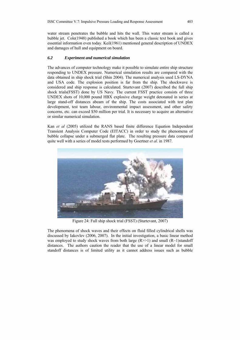
ISSC Committee V.7: Impulsive Pressure Loading and Response Assessment 403
water stream penetrates the bubble and hits the wall. This water stream is called a bubble jet. Cole(1948) published a book which has been a classic text book and gives essential information even today. Keil(1961) mentioned general description of UNDEX and damages of hull and equipment on board. 6.2 Experiment and numerical simulation
The advances of computer technology make it possible to simulate entire ship structure responding to UNDEX pressure. Numerical simulation results are compared with the data obtained in ship shock trial (Shin 2004). The numerical analysis used LS-DYNA and USA code. The explosion position is far from the ship. The shockwave is considered and ship response is calculated. Sturtevant (2007) described the full ship shock trials(FSST) done by US Navy. The current FSST practice consists of three UNDEX shots of 10,000 pound HBX explosive charge weight detonated in series at large stand-off distances abeam of the ship. The costs associated with test plan development, test team labour, environmental impact assessment, and other safety concerns, etc. can exceed $50 million per trial. It is necessary to acquire an alternative or similar numerical simulation. Kan et al (2005) utilized the RANS based finite difference Equation Independent Transient Analysis Computer Code (EITACC) in order to study the phenomena of bubble collapse under a submerged flat plate. The resulting pressure data compared quite well with a series of model tests performed by Goertner et al. in 1987.
Figure 24: Full ship shock trial (FSST) (Sturtevant, 2007)
The phenomena of shock waves and their effects on fluid filled cylindrical shells was discussed by Iakovlev (2006, 2007). In the initial investigation, a basic linear method was employed to study shock waves from both large (R>>1) and small (R~1)standoff distances. The authors caution the reader that the use of a linear model for small standoff distances is of limited utility as it cannot address issues such as bubble

404 ISSC Committee V.7: Impulsive Pressure Loading and Response Assessment
expansion and collapse, water jet impact and cavitation. However, the predicted internal shock wave is consistent with the available model test data. Hence, it may be possible to utilize a linear approach to analyze certain aspects portions of more complex fluid interacting shell systems. The follow-up study examined the effects of acoustic waves. Of particular interest is the issue of shock transparency (i.e., the ability of a shell to reduce the intensity of a shock load as it penetrates the structure) as it can be an important aspect in the design of double-hulled structures. The use of different materials (copper, steel titanium and aluminium) and their effect on transparency was examined and it was found that the more denser the material the less transparent the shell is. Based on this study, a general formulation to assess shock transparency is provided
δ = hoρs / roρf (1) δ =dimensionless mass per unit area of the shell ho = thickness of the shell ρs = density of the shell material ro = radius of the shell ρf = density of the fluid Where the smaller the the more shock transparent is the shell structure. The application of the Dynamic System Mechanics Advanced Simulation (DYSMAS) was outlined by Ripley et al (2006). The DYSMAS program is a fully coupled hydro code capable of analyzing the response of structures exposed to impulsive loadings. Plans to validate the program for use in full scale applications are discussed. When the shockwave reaches at the free surface of the water, bulk cavitation is produced. The ship’s response to the shockwave is affected with this cavitation. Gong (2006) incorporated this effect into the numerical analysis. An investigation on attenuation of floating structures response to an underwater explosion was also conducted. An explicit finite element approach interfaced with the boundary element method was used for this study. The effective structural damping and stiffness of the floating structure were formulated and incorporated in the fluid–structure-coupled equations. The present computational procedure facilitates the investigation on the attenuation effects of the floating structure response to underwater explosion. It also captures the cavitation phenomenon induced by underwater shock near free surface. The results show that, for the two-layered structure, the structural damping has a significant attenuation effect on the underwater shock response. The optimal damping material should have light weight, high modulus and high loss factor to effect the shock attenuation. For the double hull with an interlayer, the structural stiffness parameter C depends only on the geometry and Young’s modulus of the double hull. Therefore, shear modulus G is a critical factor to be considered in the floating structure design for shock attenuation.

ISSC Committee V.7: Impulsive Pressure Loading and Response Assessment 405
The results of two near-contact calculations, one an axi-symmetric charge near a thin plate and the other a three-dimensional charge near a stiffened cylinder target, are presented and compared with experiments (Gregson 2006). The large-deformation fluid-structure interaction features added to the Chinook solver were validated against two experimental tests. For the plate simulation, a reasonable agreement was found between the calculated and measured permanent deformation with a difference of 8%. For the stiffened cylinder simulation, the results were also consistent with the experimental results, with a maximum error in final wall deformation of 25.3%, and 9.1% for the stiffener. Noma(2006) developed a calculation method for the hull whipping response by the Source-Sink method. The proposed method incorporated the bubbles motion and the ship motion with interaction between them by using the Source-Sink method as an analysis method for the hull whipping response analysis for UNDEX loads. Yasuda(2006,2005) proposed numerical method to estimate ultimate bending strength of a hull girder subjected to a close in UNDEX. The method consisted of explicit FEM for the bending moment due to a close in UNDEX, BEM for the local pressure from bubble jet, explicit FEM for the local structural damage due to local pressure, and incremental collapse method for the residual strength of hull girder. For the explosion bubble, BEM is used to analyze its behaviour. Klaseboer(2005) developed a numerical analysis code which is based on BEM coupled with structural finite element code. The experimental results were compared against the numerical results for different bubble-structure configurations and orientations. Lee (2007) took the loss of system energy due to bubble pulse into account. The energy loss was incorporated into a mathematical model by a discontinuous jump in the potential energy at the minimum volume during the short collapse-rebound period accompanying wave emission. Numerical results of bubble radius time history agreed well with the experimental results up to three oscillation periods. 6.3 Classification Rules
Lloyd’s Register Rule and Regulations (2008) describes how a ship’s structure is designed by taking UNDEX into account. It also gives general information about the shock wave, bubble pulse, bubble jet and their effects to structural response. Normally, bubble loading can be ignored if the bubble never approaches within a distance of around ten times the maximum bubble radius. If the bubble is within one bubble radius of the ship structure, it is likely to form a jet that will have an impact on the structure. This bubble collapse mechanism will cause extensive local damage. The important feature of the bubble loading is its low frequency which is ideally suited to induce ship hull girder flexural motion. This flexural motion is commonly referred to as hull girder whipping. Lloyd’s defines three levels of shock notations, SH1, SH2, SH3. These notations are

406 ISSC Committee V.7: Impulsive Pressure Loading and Response Assessment
for the effects of initial shock wave. An analysis level and confirmation test level are defined for each notation. The highest notation, SH3, requires the shock trial and analysis should be done by fluid-structure interaction (FSI) modelling using a Finite Element and Volume Element approach (Hydrocode) in local strength assessment. Structural design guidance is described for each shock notation. In addition to the shock notations for initial shock wave, it defines design level, WH1, WH2, and WH3, for whipping induced by explosion bubble effects. An analysis method is given for each level. A WH1 analysis method uses a 2-D beam representation and a failure level criterion based on the bending moment to induce material yield. A WH2 method of analysis uses a 2-D beam representation and a failure level criterion based on the section ultimate bending moments. This will require assessment using ultimate strength calculations at each of the discrete sections of the hull girder beam model. A WH3 method of analysis uses a 3-D definition of a section of the hull girder and geometric and material failure criteria implicit in the chosen finite element code. Finally ships for which a residual strength assessment is carried out will be eligible for a RSA1, RSA2 or RSA3 notation. A RSA1 analysis method uses a 2-D elastic cross-section representation and a failure level criterion based on the calculated bending moment being greater than both the design hogging and sagging bending moments at the sections considered to be most critical. A RSA2 method of analysis uses a 2-D ultimate strength beam representation and a failure level criterion based on the section ultimate bending moments being satisfactory compared to the design bending moments in both hogging and sagging. This will require assessment using ultimate strength calculations at no less than three damaged positions along the length of the hull. A RSA3 method of analysis uses a 3-D definition of a section of the hull girder and relies on geometric and material failure criteria implicit in the chosen finite element code. It could also include coupled Euler-Lagrange formulations to specifically account for internal and external blast effects, UNDEX shock and whipping. Germanischer Lloyd (2004) has a rule for shock consideration. It focuses mainly on the effect of shock load on equipment and machinery rather than on the hull. The analysis utilize SRS(Shock Response Spectrum) which represents the maximum response of a linear single degree of freedom vibration system with defined damping characteristics as a function of frequency. Normally the SRS represents classified data.
7. DAMAGE TO STRUCTURES AND THEIR RESIDUAL STRENGTH
7.1 General
The structural responses to impulsive pressure loadings can be grouped into three categories: i.e., localized response, transitional response and overall response (Lewis and Gerard, 1959). Although the transition phenomenon is important, it is not creates a

ISSC Committee V.7: Impulsive Pressure Loading and Response Assessment 407
serious problem of structural failure (SNAME, 1993). Because of this most of researches reported so far are related with the local and overall responses. The scantlings of ship structures subjected to slamming, sloshing or green water are determined by the equivalent static design pressure provided in the rule book of classification societies. The maximum structural response under the design pressure is expected to be the same as when the structure is subjected to an actual impulsive pressure loading. The responses of structures under static pressure are quite well known, but those under impulsive pressure loadings have not been fully investigated yet. In this chapter, the relevant literature to predicting the permanent deflection due to impulsive pressure loadings has been reviewed. The research on the residual strength of damaged structures due to impulsive pressure loadings is also included for review. For many cases, the probable region of ship structures suffered from the damage due to impulsive pressure is away from the mid-ships where the greatest vertical bending moment may be applied. Even in the case where the strength decrease due to damage is not the matter of concern, ship owners may request the repair of damaged regions. It means that not only the ultimate limit state but the serviceability limit state need to be considered for more sensible design of marine structures against impulsive pressure loadings. 7.2 Local damage
7.2.1 Natural period of impacted structures
In predicting the permanent deflection of un-stiffened or stiffened plates subjected to impulsive pressure loadings, the natural period of the structure is a very important parameter. Samuelides et al (2007) investigated the impulse shape effects on permanent deflection for un-stiffened plates. In their study the impulse durations considered were much shorter than the natural period of the plate and they concluded that the effect of the impulse shape was negligible. Therefore, when the impulse duration is very short comparing with the structure natural period the impulse can be the only parameter representing the impulsive pressure loading. Lee et al (2004) calculated the permanent deflection of an un-stiffened plate subjected to impulsive pressure loadings varying pressure amplitude and impulse duration. It was concluded that the permanent deflection remains almost constant if the impulse duration is longer than the natural period of the plate. For stiffened plates Cho and Seo (2009) also obtained the same result. Thus it can be said that when the impulse duration time is longer than that of the structure’s natural period the pressure amplitude is the only design parameter for impulsive pressure loadings.

408 ISSC Committee V.7: Impulsive Pressure Loading and Response Assessment
When the impulse duration is not very short, comparing with the natural period of the structure but shorter than that, i. e. intermediate case, the amplitude and duration of the impulsive pressure should be considered.
(a) exterior view (b) interior view
Figure 25: Damaged structure due to flare slamming
However, for impulsive pressure loadings caused by underwater explosions, the impulse duration is much shorter than the impacted structure’s natural period. Therefore, the impulse may represent the impulsive pressure loading due to underwater explosion. Opposite to that for slamming, sloshing or green water, the duration of impulsive pressure loadings is much longer than the impacted structure’s natural period. For these cases the amplitude of impulsive pressure may represent the loading. A question still remains to be answered how to idealise the impulsive pressure loadings which has a long tail, i.e. how to obtain the equivalent dynamic amplitude of the design impulsive pressure loadings of rectangular shape. The natural period of the impacted un-stiffened or stiffened plates can be obtained by the equation derived by Szechenyi (1971). 7.2.2 Permanent deflection prediction
For un-stiffened plates subjected to very short impulsive pressure loadings due to underwater explosions, various formulations are available to predict the residual deflection. Jones (1989), Chen (1993), Nurick and Martin (1989), Saitoh, et al (1995) and Park and Cho (2006) proposed simple design equations. When stiffened plates are subjected to impulsive pressure loadings due to underwater explosion, the residual deflections can be predicted by the design equations proposed
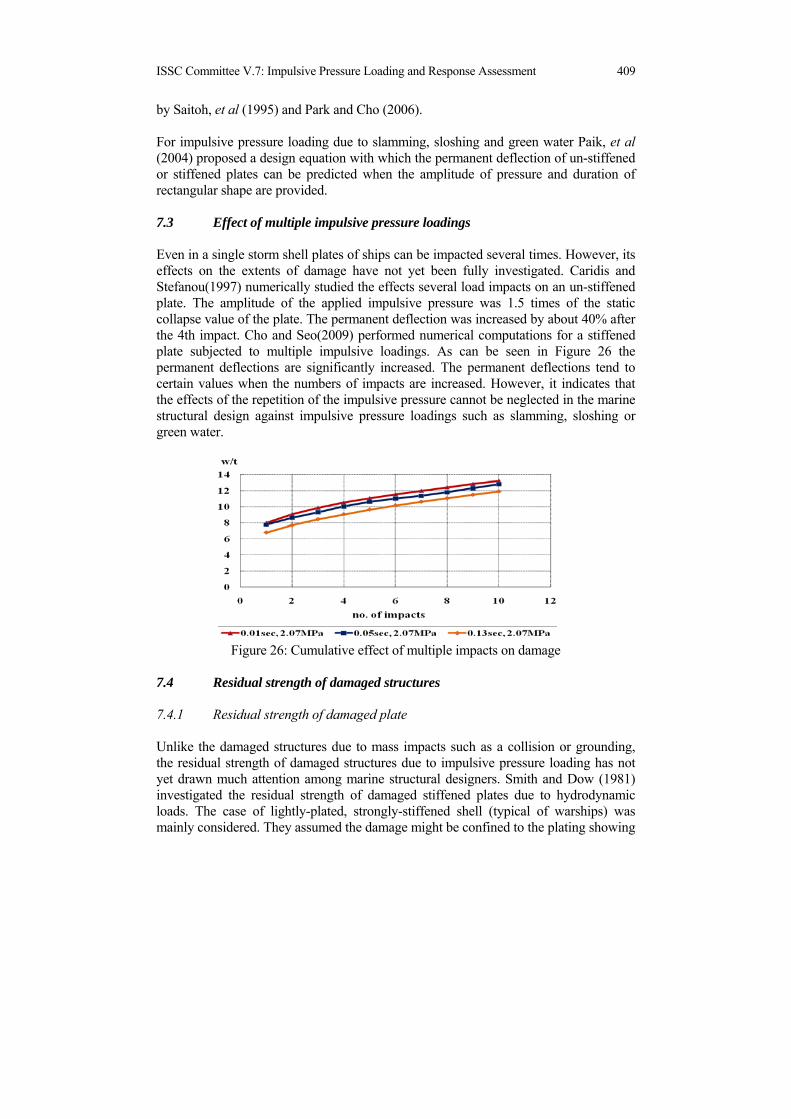
ISSC Committee V.7: Impulsive Pressure Loading and Response Assessment 409
by Saitoh, et al (1995) and Park and Cho (2006). For impulsive pressure loading due to slamming, sloshing and green water Paik, et al (2004) proposed a design equation with which the permanent deflection of un-stiffened or stiffened plates can be predicted when the amplitude of pressure and duration of rectangular shape are provided. 7.3 Effect of multiple impulsive pressure loadings
Even in a single storm shell plates of ships can be impacted several times. However, its effects on the extents of damage have not yet been fully investigated. Caridis and Stefanou(1997) numerically studied the effects several load impacts on an un-stiffened plate. The amplitude of the applied impulsive pressure was 1.5 times of the static collapse value of the plate. The permanent deflection was increased by about 40% after the 4th impact. Cho and Seo(2009) performed numerical computations for a stiffened plate subjected to multiple impulsive loadings. As can be seen in Figure 26 the permanent deflections are significantly increased. The permanent deflections tend to certain values when the numbers of impacts are increased. However, it indicates that the effects of the repetition of the impulsive pressure cannot be neglected in the marine structural design against impulsive pressure loadings such as slamming, sloshing or green water.
Figure 26: Cumulative effect of multiple impacts on damage
7.4 Residual strength of damaged structures
7.4.1 Residual strength of damaged plate
Unlike the damaged structures due to mass impacts such as a collision or grounding, the residual strength of damaged structures due to impulsive pressure loading has not yet drawn much attention among marine structural designers. Smith and Dow (1981) investigated the residual strength of damaged stiffened plates due to hydrodynamic loads. The case of lightly-plated, strongly-stiffened shell (typical of warships) was mainly considered. They assumed the damage might be confined to the plating showing
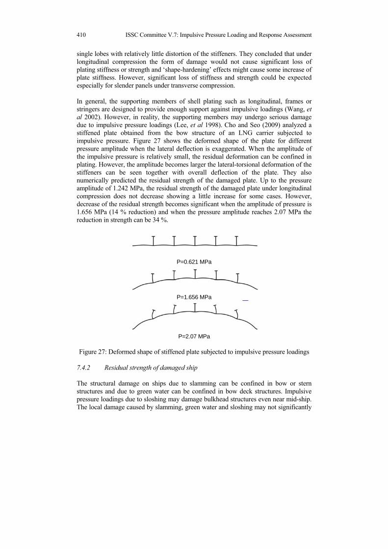
410 ISSC Committee V.7: Impulsive Pressure Loading and Response Assessment
single lobes with relatively little distortion of the stiffeners. They concluded that under longitudinal compression the form of damage would not cause significant loss of plating stiffness or strength and ‘shape-hardening’ effects might cause some increase of plate stiffness. However, significant loss of stiffness and strength could be expected especially for slender panels under transverse compression. In general, the supporting members of shell plating such as longitudinal, frames or stringers are designed to provide enough support against impulsive loadings (Wang, et al 2002). However, in reality, the supporting members may undergo serious damage due to impulsive pressure loadings (Lee, et al 1998). Cho and Seo (2009) analyzed a stiffened plate obtained from the bow structure of an LNG carrier subjected to impulsive pressure. Figure 27 shows the deformed shape of the plate for different pressure amplitude when the lateral deflection is exaggerated. When the amplitude of the impulsive pressure is relatively small, the residual deformation can be confined in plating. However, the amplitude becomes larger the lateral-torsional deformation of the stiffeners can be seen together with overall deflection of the plate. They also numerically predicted the residual strength of the damaged plate. Up to the pressure amplitude of 1.242 MPa, the residual strength of the damaged plate under longitudinal compression does not decrease showing a little increase for some cases. However, decrease of the residual strength becomes significant when the amplitude of pressure is 1.656 MPa (14 % reduction) and when the pressure amplitude reaches 2.07 MPa the reduction in strength can be 34 %.
P=0.621 MPa
P=1.656 MPa
P=2.07 MPa
Figure 27: Deformed shape of stiffened plate subjected to impulsive pressure loadings
7.4.2 Residual strength of damaged ship
The structural damage on ships due to slamming can be confined in bow or stern structures and due to green water can be confined in bow deck structures. Impulsive pressure loadings due to sloshing may damage bulkhead structures even near mid-ship. The local damage caused by slamming, green water and sloshing may not significantly

ISSC Committee V.7: Impulsive Pressure Loading and Response Assessment 411
affect the global strength of ship structures. However, underwater explosion may cause severe damage in the mid-ships region where the vertical bending moment is greatest. Many researchers assumed that the damaged structure is totally ineffective under in-plane loads and that hull section properties are reduced accordingly. Where damage is less severe, this assumption may be too conservative. Therefore, a realistic assessment of the residual stiffness and strength for the damaged structure is necessary (Smith and Dow 1981). Ren, et al (2008) investigated the statistical characteristic values of residual capability considering the uncertainties related with the size of broken hole caused by weapons, material mechanical properties of steel and the size of structures.
8. COMPARISON OF CLASSIFICATION SOCIETIES RULES
8.1 General
Traditionally, Classification Societies have made the safe requirement for the impulsive response based on a state of the art theory and many experiences. However, different procedures for the requirement have been developed according to the damage data due to the impulsive loads which each Classification Society has collect from its classed ships. Recently, IACS (International Association of Classification Societies) has implemented CSR(Common Structure Rules) for Tankers and Bulk carriers from April 1 2006. In order to investigate the different requirement for Classification Societies Rules for impulsive response, comparative calculations have been performed for a demonstration ship. The principle particulars of the demonstration example vessel are given as follows;
Ship Type : OIL TANKER with D.W. 39,000Ton LBP : 172.m Breadth(Mld.) : 31.40m Draft(Scantling; Mld.)10.95m Block Coefficient : 0.785 Design Speed : 14.5knot
8.2 Plate thickness required by the slamming pressure
The required plate thickness due to the bottom slamming pressure and bow flare slamming pressure have been calculated according to three different Classification Societies Rules and the CSR for the example ship. The calculation results are presented in Figure 28 and 29.

412 ISSC Committee V.7: Impulsive Pressure Loading and Response Assessment
0.0
5.0
10.0
15.0
20.0
25.0
30.0
35.0
0.80 0.85 0.90 0.95 1.00
Longitudinal Calculation Point / Ship LengthR
equi
red
Plat
e Th
ickn
ess(
mm
)
Class A
Class B
Class C
CSR
Figure 28: Required thickness of the bottom plate at centre line by the bottom
slamming pressure
11
12
13
14
15
16
17
18
0.0 2.0 4.0 6.0 8.0 10.0 12.0
Required Plate Thickness(mm)
Ver
tical
Disr
ance
from
abo
ve b
ase
line(
m)
Class A
Class B
Class C
CSR
Figure 29: Required thickness of the side shell plate at F.P. by bow flare slamming
pressure 8.3 Plate thickness required by the sloshing pressure
The required plate thickness due to the sloshing pressure has been calculated according to three different classification societies rules and the CSR at following structure points of no. 1 tank of the example ship;
H(Tank Height) = 15.1m lc(Longitudinal distance of the tank)= 17.40m bc(Transverse distance of the tank)= 24.94m h(Filling Height) = 10.57m(0.7H) Calculated point = 10.57m(0.7H)
The calculation results are shown in Table 1.

ISSC Committee V.7: Impulsive Pressure Loading and Response Assessment 413
Table 1 Required plate thickness by sloshing pressure (mm)
Calculated point Class A Class B Class C CSR Transverse Bulkhead 9.5 8.93 6.51 6.35
Longitudinal bulkhead 9.5 10.95 8.60 8.60
8.4 Plate thickness required by the green water loads
The required plate thicknesses due to the green water loads have been calculated according to three different Classification Societies Rules and the CSR for the example ship. The calculation results are plotted in Figure 30.
0.0
2.0
4.0
6.0
8.0
10.0
12.0
0.75 0.80 0.85 0.90 0.95 1.00 1.05
Longitudinal Calculation Point / Ship Length
Req
uire
d Pl
ate
Thc
knes
s(m
m)
Class A
Class B
Class C
CSR
Figure 30: Required thickness of the deck plate by green sea loads
9. RECOMMENDATIONS FOR STRUCTURAL DESIGN GUIDANCE
General Impulsive pressure loadings can affect the ship structure both locally and globally. Local structural damage is caused by the local pressure action on the hydro-structure interface, while the global impulsive loading can induce the overall ship vibrations known as whipping. Whipping can increase the bending moment and shear force. The extreme difficulties related to the proper modelling of the impulsive pressure loading and the associated structural responses clearly appear throughout all the chapters of this report. This is probably one of the most difficult aspects of the hydro structure interactions in ship design. Indeed a very complex hydrodynamic flow needs to be coupled with the evaluation of the structural response. Whether this coupling

414 ISSC Committee V.7: Impulsive Pressure Loading and Response Assessment
should be weak or strong mainly depends on the ratio of the impulse duration relative to the natural period of the impacted structure. Generally, in the case when the impulse duration is long enough hydro and structural calculations can be performed separately and structural response can be calculated within the quasi static assumptions. In the opposite case of very short impulse duration, the structural response will be negligible. In the intermediate cases a fully coupled hydro structure modelling is necessary. In hoping to improve the quality of the marine structural design against impulsive pressure loadings, some recommendations are provided herein based upon the reviews and investigations performed by the committee. Impulsive pressure loading There are several relatively independent technical difficulties associated with the calculation of the impulsive pressure loading:
Determination of the exact impact conditions Calculation of the hydrodynamic impact loads Modelling of the structure Hydroelastic coupling
It is fair to say that none of the above aspects is fully mastered today neither numerically neither experimentally, even if the significant progress was made during the last decade. The main impact parameters can be defined by the relative impact geometry, relative velocity and amount of the entrapped air. The proper determination of these quantities, either for slamming or sloshing, remain extremely challenging, since the overall seakeeping problem of ship sailing with arbitrary forward speed in waves is still an open problem. Only the approximate general tendencies can be determined and after that the parametric studies need to be performed in order to check the sensitivity of the structural responses to the different impact parameters. On the other hand, even if the impact conditions are assumed to be known the correct modelling of the fluid flow during the impact is extremely complex. As a matter of fact only 2D methods seem to be practically feasible today, even if some attempts for 3D impact modelling were investigated. In the case of ship slamming, the modelling of structure is much simpler when compared to the modelling of the complex containment system in the tanks of LNG Carriers. Finally when coming to the full hydroelastic coupling the things become very complicated and only relatively simple hydro-structure interaction situations can be handled with confidence. Local slamming Numerical predictions of slamming pressures accounting for viscous flow separation, entrapped air, compressibility of fluids and elasticity of structures need to enhance their accuracy, stability and efficiency. More validations with tests results are needed for

ISSC Committee V.7: Impulsive Pressure Loading and Response Assessment 415
application of these methods in design practice. With the development of seakeeping theory and programs, more ship’s motion parameters should be included in practical impulsive load prediction procedures. Global slamming Generally, 3D effects can reduce the 2D slamming pressure force significantly. Fully 3D slamming prediction methods are not ready for use in a global response analysis. Correction factors on 2D estimates may be applied to yield reasonable values for design. In global slamming analysis, the computational efforts and costs are very much larger for FE models compared to beam models. However, quite accurate results are obtained if the beam model is based on advanced thin-walled girder theory, with included shear influence on torsion. Therefore, for conceptual design it is more rational and convenient to couple 1D FEM model of ship hull with a 3D hydrodynamic model. The contribution from vibratory response may double the fatigue damage induced by wave-frequency loads for bulk and container carriers. The damping may play an important role in numerical analysis and measurements. Therefore, it is important to control the damping in model tests to correspond to that for real ships. Sloshing It is common in tank design to do model experiments for sloshing-induced impact effects by means of forced oscillation tests. However, the scaling of the model-test results represents a challenge due to the many physical effects that may matter. Usually, the Froude scaling is applied for small scale model tests. This formulation yields conservative values for maximum pressure. However, it is important to note that the time is also differently scaled by different scaling laws. The relationship between temporal characteristics of the load and the structural response is nonlinear and dependent on these characteristics related to the natural period of the structure. Therefore, the effect of scaling the pressure time histories may only be assessed by analyzing the dynamic response of the containment system. In spite of all the efforts which were made in order to properly solve the sloshing impact issues, it is fair to mention that still many lots of uncertainties persist and it is not fully clear how they could be properly solved. The full scale monitoring of the real LNG ships under their normal operation would certainly be very helpful but, for the time being, it seems to be very difficult to perform these kinds of measurements. Recently reported damages on large LNG carriers clearly show that the important improvements of the methodology for structural assessment of the LNG containment systems are necessary. The possibility to perform the tests with the real LNG at large or full scale should also be investigated, even if the practical realisation of these tests appears very complex. In any case, the actual design procedure based on different comparative approaches or on prescribed empirical pressure distributions should be improved

416 ISSC Committee V.7: Impulsive Pressure Loading and Response Assessment
Green water Due to the variety of numerical approaches that have been used to solve the water shipping problem, a benchmarking would be indeed appreciable to compare both accuracy and computational costs. In this perspective, the dam-break problem seems to be the obvious candidate to provide a shared set of data. The use of new experimental techniques to investigate the two-layer flow details allows to compare numerical results and flow data also in terms of both velocity fields inside the rushing water and contours of the air-entrapment regions. Nonetheless, if the final goal is to provide loads to be applied to the ship super-structures, it seems important to assume the pressure estimation capability as the main indicator of the accuracy of the different approaches. Since the pressure measure may be also affected by errors and remarkable sensitivity to time and sensor position, especially in a mixed flow environment, the measurement of global loads, for instance shear forces and bending moments on flexible decks and walls, should be successfully exploited to facilitate the comparison between simulations and experiments. It seems in any case opportune that uncertainty analysis is applied to investigate the accuracy of the tests. In general, the evaluation of the occurrence and intensity of green water loads should constitute a fundamental input for the broad objective to assess the survivability and structural integrity of the ship. In particular, two aspects need to be considered in this analysis: the strength of deck structures exposed to green water and, in the case of water ingress and subsequent flooding of any ship holds, the strength of structural elements internally loaded by sloshing water. Generally, forepeak structures and closures, forward hatch coamings and forward hatch covers are usually the elements mainly subjected to collapse under water impact on the deck. On the other hand, if the inner part of the ship structure is wetted, transverse bulkheads, double bottom, side shell and transverse frames are found to be at risk of failure under this condition. Impulse shape The impulsive pressure loading history, especially of slamming, can be idealised as shown in Figure 31, which has a very sharp peak followed by a long tail of relatively low pressure. It has been saying that the duration of the impulse is much longer than the natural period of the impacted structure and the response of the structures can be treated as quasi-static problems. However, if the amplitude of the pressure of the tail part is much smaller than that of the peak pressure, which is true for the most of reported cases for slamming, the effects of the tail part on the extent of damage of the impacted pressure is very small. At this juncture, a question may be raised whether the duration or the peak width is more meaningful parameter. According to numerical calculation results the peak pressure and the peak width are two most influential parameters to the extent of damages of impacted structures. Unfortunately, most of experimental or theoretical investigations reported in the open literature so far are focused on how to accurately predict the peak pressure. But those

ISSC Committee V.7: Impulsive Pressure Loading and Response Assessment 417
on the peak width are very few. Therefore, it is difficult to measure that from the pressure history diagrams obtained either by experiments or theoretical calculations. Further research is urgently necessary to obtain the information regarding the peak width of the impulsive pressure loadings.
Figure 31: Idealised impulsive pressure history (Lee et al, 1998)
Multiple impacts Even in a single storm shell plates of ships can be impacted several times. Theoretically, if the static loads of same level are applied several times the extents of damage cannot be changed. However, for impact loadings the extent of damage can be accumulated by multiple applications of impact. The effects multiple impacts on the extents of damage have not yet been considered in any classification societies rules yet. According to some experimental and numerical investigation results the increase of extents of damage of plates due to multiple impacts can be about 50%. The effects on the extents of damage on stiffeners have not reported in the open literature. Further detailed investigations are necessary regarding this effect. However, for the time being, it may be recommended that the effect of multiple impacts on the extent of damage can be simply estimated as 50% of the single impact result. Torsional strength of stiffener In classification societies rules the impulsive pressure loadings are considered in the structural design by increasing the plate thickness and the section modulus of stiffener which represents the bending strength of the stiffener. In many damage cases reported the torsional deformations of stiffeners of damaged parts are clearly seen.

418 ISSC Committee V.7: Impulsive Pressure Loading and Response Assessment
Figure 32: Deployment example of tripping brackets in bow area
Therefore any criteria should be provided with which the torsional strength of the stiffener can be checked. Deployment of additional tripping brackets in the region can be a practical measure where impulsive loadings are expected. In Figure 32 an example of deploying additional tripping brackets can be seen. The additional tripping brackets can increase the torsional resistance of the stiffeners and reduce the aspect ratios of plates, which will be resulted in reducing the deflections of plates against impulsive pressure. Angle between the curved plating and the stiffener may affect the torsional resistance of the stiffener. Unless the angle is 90o the torsional resistance of the stiffener against impulsive pressure can be reduced. The effects of this angle need to be investigated. Allowable extent of damage Avoiding the damage due to impulsive pressure loadings seems not practical. Therefore, specifying of the allowable extents of damage due to impulsive pressure loadings seems necessary for more rational and practical structural design. The damage in the regions of fore or after part of a ship may not significantly influence the ultimate strength where the global loading is usually small. However, if the damage is apparent some repair works will be required. In determining the allowable extents of damage some optimisation procedures need to be invoked considering the initial construction costs, operational expenses and direct and indirect repair costs. Probabilistic approaches are also necessary to determine the occurrence of damage. Previous experiences and records regarding the repair works due to pressure impacts will be valuable data for the procedures. Reverse engineering of damage records In predicting the impulsive pressure loadings induced by slamming, sloshing, green water and underwater explosion still intolerable uncertainties exist even though various research has been performed to improve the accuracy of assessments. For specified impulsive pressure loadings the responses of impacted structures can be traced by commercial numerical packages with confidence in these days.

ISSC Committee V.7: Impulsive Pressure Loading and Response Assessment 419
It is believed that classification societies and ship yards keep various damage records due to impulsive pressure loadings. However, most of those records are not opened to public because of the confidentiality. The actual damage records may unveil valuable information which could improve related technologies and prediction accuracy accordingly. In this regard collaborations between related organisations are required.
10. CONCLUSIONS
Local slamming Model or full-scale tests still remain to be the most reliable approach in obtaining the pressure distribution and force on temporal and spatial scale, especially in disturbed water. Analytical approaches have been developed to a high degree of accuracy in predicting the impulsive slamming pressures in calm water for most deadrise angles of the body with simple profiles. Numerical simulations of the slamming pressures have been greatly developed with acceptable accuracy and efficiency. Commercial or in-house software based on CFD technique have attracted more attentions in recent years and is an encouraging prospect. Due to the complexity of the slamming phenomenon, practical method to obtain rational design pressure, force and structural dynamic response for a new real design is still required. Global slamming Due to the 3D characteristics of the bow flare, the direct adoption of any 2D methods will induce some error. This is a particular issue for ship sections with a relative roll angle during the impact. The 3D character of the bow and bulb of container ships is particularly challenging to model. While FE methods provide excellent tools for modeling the structural behaviour, the main challenge in estimating global slamming response is the calculation of slamming force, especially in oblique seas due to the effect of roll motion. However, the full FE models of complex ship structures are still quite computationally demanding and combined use of simple models and refined models in a hierarchical approach is useful. The high frequency fatigue damage due to whipping can be significantly reduced by including the steady wave for the relevant vessel, implying better agreement with the experimental results. Therefore, more work needs to be done to improve the high frequency stress modeling. This includes amongst others identifying and quantifying the sources of damping of the vibration and verification of the excitation sources of the high frequency response. Sloshing Sloshing induced impacts are important in the design of a ship’s tank. Many physical

420 ISSC Committee V.7: Impulsive Pressure Loading and Response Assessment
effects may have to be considered such as gas cushion, liquid compressibility, boiling of liquid cargoes and hydroelasticity. When analyzing sloshing impacts, one must always have the structural response in mind. An important consideration is the time scale of a particular hydrodynamic effect relative to wet natural periods for structural modes contributing significantly to large structural stresses. More structural modes may be included for membrane structures analyses than for steel structures. Some of the important structural modes for membrane structures may have relatively longer natural periods than for steel structures. If the time scale of a hydrodynamic effect is very short relative to important structural natural periods, the structure has a negligible reaction and, therefore, the particular hydrodynamic/hydroelastic effect can be neglected. When the hydrodynamic loads occur on the time scale of important structural modes, hydroelasticity must be considered. This implies that the fluid (liquid, gas) flow must be solved simultaneously with the dynamic elastic structural reaction. The quasi full scale model tests and intermediate scale model tests are believed to bring more light into this difficult problem. Several experimental campaigns are underway nowadays, but still no clear and reliable results were published. Green water Because green water loading is an important aspect in the safety of ships, it should be taken into account in the design, following the common sense recommendation to prevent it as far as possible and protect against the remaining part. The structural damage that may be generated by green water events depends primarily on the possibility that such events occur, that demands to prevent large relative motion at bow in heavy weather. Apart from an appropriate ship management (e.g., non-use of alternate hold loading in heavy cargos), this goal requires an optimum design of the hull shape, avoiding those factors that may seriously contribute to worsen the situation, like large longitudinal inertia and reduction in freeboard, and focusing on others, like the flare angle, that play an important role for deck wetness. Different measures can be investigated to reduce the effects of green water on the deck. Forward protection may be achieved in the form of forecastle and breakwater, side protection by means of walls, in general structural barriers can be installed where critical equipment is exposed to this risk. Breakwaters are usually employed as a sacrificial object to sustain the green water loading at initial stage, diverting it from the containers or from other critical elements. The proper choice of their shape (V-shape, vane-type, with holes) and layout on the deck needs to be carefully considered to avoid that the flow is concentrated on unprotected points. Underwater explosion

ISSC Committee V.7: Impulsive Pressure Loading and Response Assessment 421
A number of interesting investigations have been conducted recently. They are mainly on the numerical simulations. FEM seems to be the most powerful tool for the simulation but the calculation cost is still high. Numerical calculation techniques such as parallel computation will be needed and applied for a large scale model which has over 1,000,000 elements. 3D CAD must be indispensable for quick and precise FEM modelling of structures, equipments, and surrounding fluid. On the other hand, simple method like a hull girder with BEM loading is a desirable tool in the early stages of design. It should be mentioned that one must recognize what is neglected and where is the limit of the method when a simple method is developed. Needless to say, experiments and tests are always important for checking validation of the numerical method and for confirmation of the design. A real scale experiment using explosives has a high risk on environments and is expensive. Alternative way to produce shockwaves and gas bubble needs to be developed for safe experiments although high pressure shockwave is hazardous in any event. The amount of explosive used in the experiment should be as small as possible. Therefore the design evaluation for strong UNDEX requires extrapolation from experimental results or depends on direct numerical calculation. A wide variety of numerical method will be developed and selected to be used in the design according to their capability and limitation. Damage to structures and their residual strength In predicting the permanent deflection of un-stiffened of stiffened plates subjected to impulsive pressure loadings, the natural period of the structure is a very influential parameter. When the impulse duration is longer than the natural period of the impacted structure, the amplitude of the impulse is the only decisive parameter for rectangular type impulse. However, the duration of impulse is very short comparing with the natural period of the impacted structure the impulse can be the only parameter representing the impulsive pressure loading regardless of its shape. But for intermediate cases the amplitude and duration of the impulsive pressure should be considered. Even in a single storm shell plates of ships can be impacted several times. Therefore, the effects of multiple impulsive pressure loadings on the extent of damage should be investigated. According to the numerical and experimental studies reported in the open literature so far the permanent deflection of un-stiffened or stiffened plates can be increased and approach to about one and half times of that of the first impact. When the applied impulse to stiffened plates is not severe the damage can be confined in plates and the deformation of stiffeners is not significant. Furthermore, the form of damage would not cause significant loss of plating stiffness or strength and ‘shape-hardening’ effects might cause some increase of the residual strength of the damaged plate under axial compression. However, the amplitude becomes larger the lateral-torsional deformation of the stiffeners can be seen together with overall deflection of the plate causing reduction in strength.

422 ISSC Committee V.7: Impulsive Pressure Loading and Response Assessment
Comparison of classification societies rules In order to investigate the requirements of three different classification societies rules together with Common Structure Rules for impulsive response, comparative calculations have been performed for an oil tanker of D. W. 39,000 ton. Bottom slamming, bow flare slamming, sloshing and green water pressures are calculated and the required plate thicknesses are obtained. Big differences can be found in the requirements for impulsive response. Recommendations for structural design guidance In hoping to improve the quality of the marine structural design against impulsive pressure loadings, some recommendations are provided herein based upon the reviews and investigations performed by the committee. Recently various investigations have been conducted to improve the accuracy of predictions and efficiency and stability of related calculations regarding the impulsive pressure loadings induced by slamming, sloshing, green water and underwater explosion. Modifications of relevant classification society rules are necessary accounting the recent progresses. The information regarding the peak width of impulsive pressure history is necessary for more correct identification of the structural responses under impulsive pressure loading. The effects of multiple impacts on the extent of damage need to be investigated further. The torsional strength of stiffeners is required to be specified for more rational structural design against impulsive pressure loading. Avoiding the damage due to impulsive pressure loading seems not practical. Therefore, specification of allowable extent of damage needs to be provided in relevant rules. The damage records will be very helpful to improve the current design practice. In this regard, collaborations between related organisations are required.
REFERENCES
Abramson, H.N., Bass, R.L., Faltinsen, O.M. and Olsen, H.A. (1974). Liquid slosh in LNG Carriers. Proc. 10th Symp. on Naval Hydrodynamics, Cambridge, USA: ACR-204, 371-388. Published also as Faltinsen, O.M., Olsen, H., Abramson, H.N. and Bass, R.L. (1974) Liquid Slosh in LNG Carriers. Technical Report 85, Det Norske Veritas.
Alberts, P.J. and Nieuwenhuijs, M.W. (2006). Full scale wave and whipping induced hull girder loads. Proc. 4th Int. Conf. on Hydroelasticity in Marine Technology, Wuxi, China, 65–78.
Applebee, T. et al (2008). Report of the Seakeeping Committee. Proc. 25th ITTC, Fukuoka, Japan.
Baarholm, G. S. and Moan, T. (2001). Application of contour line method to estimate extreme ship hull loads considering operational restrictions. J. Ship Research,

ISSC Committee V.7: Impulsive Pressure Loading and Response Assessment 423
45:3, 227-239. Bass, R.L. et al (1985). Modelling criteria for scaled LNG sloshing experiments. J.
Fluids Engineering. Trans. ASME, 107, 272-280. Bishop, R.E.D., Price, W.G. and Tam, P.K.Y. (1980). A unified dynamic analysis of
antisymmetric ship response to waves. Trans. RINA, 112, 349–65. Brosset, L., Mravak, Z., Kaminski, M., Collins, S. and Finnigan, T. (2009). Overview
of Sloshel project. Proc. 19th Int. Offshore and Polar Engineering Conf., Osaka, Japan.
Bunnik, T. and Huijsmans, R.H.M. (2007). Large scale LNG sloshing model tests. Proc. 17th Int. Offshore and Polar Engineering, Lisbon, Portugal.
Cao, Z. and Wu, W. (2007). The effect of air cushion on the slamming pressure peak value of trimaran cross structure. Proc 9th Int. Conf. on Fast Sea Transportation, Shanghai, China, 608-611.
Caradis, P.A. and Stefanou, M.,(1997). Dynamic elastic/viscoplastic response of hull plating subjected to hydrodynamic wave impact. J. Ship Rresearch, 41:2, 130-146.
Carrera, G. and Rizzo, C. M. (2005). Measurements of motions, loads and structural response on a fast FRP pleasure craft. Proc. 8th Int. Conf. on Fast Sea Transportation, St. Petersburg, Russia. 325-332.
Chen, W. (1993). A new bound solution for quadrangular plates subjected to impulsive loads. Proc. 3rd Int. Offshore and Polar Engineering Conf., IV, 702-12.
Chen, Z. and Xiao, X. (2005). Prediction of slamming pressure on a flat-bottom structure by means of neural network. (in Chinese), J. Ocean Engineering, 23:2, 26-31.
Chen, Z. and Xiao, X. (2006). About the slamming pressure peak value on a flat-bottom structure. (in Chinese), J. Shanghai Jiaotong University, 40:6, 983-987.
Cho, S.R. and Seo, J.S. (2009). Response characteristics of stiffened plates subjected to impulsive pressure loadings. (in Korean), J. Society of Naval Architects of Korea(to be appeared).
Chuang, S.L. (1970) . Investigation of impact of rigid and elastic bodies with water. NSRDC, AD702727.
Cole, R. H. (1948). Underwater Explosion, Princeton University Press. Cusano, G., Sebastiani, L. and Bacicchi, G. (2007). Assessment of Whipping Effects
Induced by Stern/Bow-flare Slamming. 10th Int. Symp. on Practical Design of Ships and Other Floating Structures. Houston, USA, PRADS2007- 20189.
Dessi, D., De Luca, M., Mariani, R. and Carapellotti, D. (2007). Analysis of the ship response to stern slamming loads. 10th Int. Symp. on Practical Design of Ships and Other Floating Structures, Houston, USA, PRADS2007- 20152.
Dessi, D. and Mariani, R. (2006a). Slamming load analysis of a fast vessel in regular waves: a combined experimental/numerical approach. Proc. 26th Symp. on Naval Hydrodynamics, Rome, Italy.
Dessi, D. and Mariani, R. (2006b). Experimental investigation of the ship response to bow and stern slamming loads. Proc. 4th Int. Conf. on Hydroelasticity in Marine Technology, Wuxi, China, 79–88.
Dietz, J., Schjoldager, F., Hansen, P. and Jensen, J.J. (2004). Design wave episodes for

424 ISSC Committee V.7: Impulsive Pressure Loading and Response Assessment
extreme value ship responses. Proc. 9th Int. Symp. on Practical Design of Ships and Other Floating Structures, Luebeck-Travemünde, Germany , Published by STG,
DNV, (2005). Rules for ships-standard contents : Part 3. Hull and equipment - main class.
Dobashi, J. (2006). Influence of the body shape and trapped-air on the water impact problem. J. Japan Society of Naval Architects and Ocean Engineers, 3,183-188.
Dobashi, J. (2007). The water impact problem with the trapped air on the heeled body. J.Japan Society of Naval Architects and Ocean Engineers, 5.177-183.
Drummen, I., Moan, T., Storhaug, G. and Moe, E., (2006). Experimental and full scale investigation of the importance of fatigue damage due to wave-induced vibration stress in a container vessel. Proc. RINA Conf. on Design & Operation of Container Ships, London, UK, 61-74.
Drummen, I. and Moan, T. (2007). Experimental investigation of the application of response conditioned waves for long-term nonlinear analyses. 10th Int. Symp. on Practical Design of Ships and Other Floating Structures, Houston, USA.
Drummen, I., Storhaug, G. and Moan, T. (2008). Experimental and numerical investigation of fatigue damage due to wave-induced vibrations in a containership in head seas. J. Marine Science and Technology, 13:4, 428-445.
Elias, R.N. and Coutinho, L. G. A. (2007). Stabilized edge-based finite element simulation of free-surface flows, Int. J. for Numerical Methods in Fluids, 54, 965–993.
El Moctar, O.A., Jörg, B., Andreas B. and Schellin, T.E. (2005). Computation of ship motions in waves and slamming loads for fast ships using RANSE. Proc. Int. Conf. on Fast Sea Transportation, St.Petersburg, Russia. 259-269.
Faltinsen, O.M. and Chezhian, M. (2005). A generalized Wagner method for three-dimensional slamming. J. Ship Research, 49:4, 279-287.
Faltinsen, O. M, Timokha, A. N., (2009), Sloshing, Cambridge University Press. Fekken, G. (1998). Numerical simulation of green water loading on the foredeck of a
ship. MSc thesis, University of Groningen. Finn, P., Beck, R.F., Troesch, A.W. and Shin, Y.S. (2002). Nonlinear impact loading in
an oblique seaway. J. Offshore Mechanics and Arctic Engineering, 125:3, 190-197.
Fonseca, N. and Guedes Soares, C. (2004). Validation of a time-domain strip method to calculate the motions and loads on a fast monohull. Applied Ocean Research, 26, 256–273.
Fonseca, N. and Guedes Soares, C. (2005a). Experimental investigation of the shipping of water on the bow of a containership. J. Offshore Mechanics and Arctic Engineering, 127, 322-330.
Fonseca, N. and Guedes Soares, C. (2005b). Comparison between experimental and numerical results of the nonlinear vertical ship motions and loads on a containership in regular waves. Int. Shipbuilding Progress, 52:1, 57-89.
Fullerton, A.M., Fu, T. C. and Hess, D. E., (2007). Investigation and prediction of wave impact loads on ship appendage shapes. Proc. 26th Int. Conf. on Offshore Mechanics and Arctic Engineering, San Diego, California, USA, 451-456.

ISSC Committee V.7: Impulsive Pressure Loading and Response Assessment 425
Gao, Z. and Moan, T. (2008). Frequency-domain fatigue analysis of wide-band stationary Gaussian processes using a trimodal spectral formulation. Int. J. Fatigue, 30:10-11, 1944-1955.
Gazzola T. (2007). Contribution aux problèmes d’impacts non linéaires : le problème de Wagner couplé. PhD Thesis, Ecole Centrale Paris.
Ge, C., Faltinsen, O. and Moan, T. (2005). Global hydroelastic response of catamarans due to wetdeck slamming. J. Ship Research, 49:1, 24-42.
Germanischer Lloyd Rules for Classification and Construction (2004) Ⅲ Naval ship technology 1 Surface ships 1 Hull structures and ship equipment Part 1 Section 16 Noise, vibration and shock consideration.
Gong, S.W. and Lam, K.Y. (2006). On attenuation of floating structure response to underwater shock. Int. J. Impact Engineering, 32, 1857–1877.
Graczyk, M., Moan, T. and Rognebakke, O. (2006). Probabilistic analysis of characteristic pressure for LNG tanks. J. Offshore Mechanics and Arctic Engineering, 128, 133-144.
Graczyk, M. and Moan, T. (2009). Structural response to sloshing excitation in membrane LNG tank. J. Marine Science and Technology, (Submitted).
Graczyk, M., Moan, T. and Wu, M.K. (2007). Extreme sloshing and whipping-induced pressures and structural response in membrane LNG tanks. J. Ships and Offshore Structures, 2:3, 201–216.
Greco, M., Landrini, M. and Faltinsen, O.M. (2005). Shipping of water on a two-dimensional structure. J. of Fluid Mech., 525, 309-332.
Greco, M., Colicchio G. and Faltinsen O.M. (2007). Shipping of water on a two-dimensional structure. Part 2. J. of Fluid Mech., 581, 371-399.
Gregson, J., Link ,R. and Lee, J. (2006). Coupled simulation of the response of targets to close proximity underwater explosions in two and three dimensions. Proc. Shock and Vibration Symp., CD-R.
Hermundstad, O. A. and Moan, T. (2007). Efficient calculation of slamming pressures on ships in irregular seas. J. Marine Science and Technology , 12, 60–182.
Hermundstad, O. A. and Moan T. (2005). Numerical and experimental analysis of bow flare slamming on a Ro–Ro vessel in regular oblique waves. J. Marine Science and Technology, 10, 105–122.
Higo and Yamada. (2006). A study on the correlation between impact pressure and impact sound generated by water drops. J. Japan Society of Naval Architects and Ocean Engineers, 3. 13-18.
Hirt, C.W. and Nichols, B.D. (1981). Volume of fluid (VOF) methods for the dynamics of free boundaries. J. Computational Physics, 39, 201–225.
Huijsmans R., Tritschler G., Gaillarde G. and Dallinga R.P. (2004). Sloshing in partially filled LNG carriers. Proc. 14th Int. Offshore and Polar Engineering Conf., Toulon, France.
Hu C., Kishev Z., Kashiwagi M., Sueyoshi M. and Faltinsen O. (2006). Application of CIP method for strongly nonlinear marine hydrodynamics. Ship Technology Research, 53:2, 74–87.
Huang, W. and Moan, T.(2007). A practical formulation for evaluating combined fatigue damage from high- and low-frequency loads. J. Offshore Mechanics and

426 ISSC Committee V.7: Impulsive Pressure Loading and Response Assessment
Arctic Engineering, 129:1, 1-8. IACS, (2008). Rules for double hull oil tankers. IACS (1999). Rec.No.56 Fatigue assessment of ship structures. Iakovlev, S. (2006). External shock loading on a submerged fluid-filled cylindrical
shell. J. Fluids and Structures, 22, Issue 8997-1028. Iakovlev, S. (2007). Submerged fluid-filled cylindrical shell subjected to a shock wave:
Fluid-structure interaction effects. J. Fluids and Structures, 23:1, 117-142. Iijima, K., Yao, T. and Moan, T.(2008). Structural response of a ship in severe seas
considering global hydroelastic vibrations. Marine Structures, 21:4, 420-445. Jang, C.D., Jung, J.J. and Korobkin, A.A. (2007). An approach to estimate the hull
girder response of a ship due to springing. J. Marine Science and Technology, 12, 95-101.
Jones, N. (1989), Structural impact, Cambridge University Press, Cambridge, UK. Jensen, J.J. et al (2000). Report of ISSC Committee VI.1: Extreme hull girder loading.
Proc. 14th ISSC. Nagasaki, Japan, Elsevier, Amsterdam. Kan, K., Stuhmiller, J. and Chan, P. (2005). Simulation of the collapse of an
underwater explosion bubble under a circular plate. Shock and Vibration, 12:3, 217-225.
Keil, A.H. (1961). The response of ships to underwater explosion. Trans. SNAME, 69, 366-410.
Kim W S, Nam S K, Noh B J, Lee H S, Kim J W, Mravak Z, de Lauzon J, Maguire J R, Radosavljevic D, Kwon S H and Chung J Y. (2008). Fluid-structure interaction modelling, relating to membrane LNG ship cargo containment system. Proc. 18th Int. Offshore and Polar Engineering Conf., Vancouver, Canada.
Klaseboer, E., Hung, K.C., Wang, C., Wang, C.W., Khoo, B.C., Boyce, P., Debono, S. and Charlier, H. (2005). Experimental and numerical investigation of the dynamics of an underwater explosion bubble near a resilient/rigid structure. J. Fluid Mechanics, 537, 387-413.
Kleefsman, K.M.T., Fekken, G., Veldman, A.E.P., Iwanowski, B. and Buchner, B. (2005). A volume-of-fluid based simulation method for wave impact problems. J. Computational Physics, 206, 363–393.
Korobkin, A, Gueret, R. and Malenica S. (2006a). Hydroelastic coupling of beam finite element model with Wagner theory of water impact. J. Fluids and Structures 22, 493–504.
Korobkin A.A. and Scolan Y.-M. (2006b). Three-dimensional theory of water impact. Part 2. Linearized Wagner problem. J. Fluid Mechanics , 549, 343-373.
Korobkin A.A. and Malenica S. (2006c). Local hydroelastic models for sloshing impacts. Bureau Veritas Report NT2912.
Kota, R. and Moan, T.(2008). Stochastic Analysis of Vertical Wave Loads on Deck. Proc. 27th Conf. Offshore Mechanics and Arctic Engineering, Estoril, Portugal, OMAE2008-57105.
KR, (2008). Rules for the Classification of Steel Ships : Part 3. Hull Structures. Landrini, M., Colagrossi, A. and Faltinsen, O. M. (2003). Sloshing and slamming in 2-
D flows by the SPH Method. In Proc. 8th Int. Conf. on Numerical Ship Hydrodynamics, Busan, Korea.

ISSC Committee V.7: Impulsive Pressure Loading and Response Assessment 427
Lee H, Kim J W, Hwang C (2004). Dynamic strength analysis for membrane type LNG containment system due to sloshing impact load. In Proceedings of the International Conference on Design & Operation of Gas Carriers, London, UK.
Lee, H.S., Kwon, S.H., Lee, J.H., Jung, B.H. and Song, K.J. (2005). Slamming load analysis. Journal of Ocean Engineering and Technology, 19:4, 15-20.
Lee, M., Klaseboer, E. and Khoo, B.C. (2007). On the Boundary Integral Method for the Rebounding Bubble. Journal of Fluid Mechanics , 570 , 407-429.
Lee, S.G., Choi, K.S., Kim, M.S., Lee, K.S. and Park, J.W.(1998). A study on Prediction of Impact Loads of Bow Structure. Proc. 8th Int. Offshore and Polar Engineering Conf., Montreal, Canada, IV, 353-360.
Lee, T.K., Rim C.W., Kim, Y.N., Heo, J.H. and Kim, B.H. (2007). A study on measurement of flare slamming of large container vessel (II)-characteristic analysis of measured slamming pressure. (in Korean), J. Society of Naval Architects of Korea, 44:3, 279-284.
Lewis, E.V. and Gerard, G. (1959). A long range research program in ship structural design. Ship Structure Committee, Report No. SSC-124.
Lin, W.M., Zhang, S., Weems, K., Jones, P. and Meinhold, M. (2007). Numerical simulation and validation study of wetdeck slamming on high speed catamaran. Proc. 9th Int. Conf. in Numerical Ship Hydrodynamics, Michigan, USA.
Lloyd’s Register Rules and Regulations (January 2008) Rules and regulation for the classification of naval ships volume 1 Ship structures part 4 Military Design and Special Features chapter 2 Military Load Specifications section 5 Underwater explosion(shock).
Luo, H., Qiu, Q. and Wan, Z.Q. (2007a). Experimental study of whipping responses induced by stern slamming loads. 10th Int. Symp. on Practical Design of Ships and Other Floating Structures, Houston, USA, PRADS2007-20204.
Luo, H., Wan, Z, Qiu, Q. and Gu, X. (2007b). Numerical simulation of whipping responses induced by stern slamming loads in following waves. Proc. 9th Int. Conf. on Fast Sea Transportation, Shanghai, China.
Malenica, Š., Korobkin ,A.A., Scolan, Y.M., Gueret, R., Delafosse, V., Gazzola, T., Mravak, Z. , Chen, X.B and Zalar, M. (2006). Hydroelastic impacts in the tanks of LNG carriers. Proc. of 4th Int. Conf. on Hydroelasticity, Wuxi, China.
Malenica, Š., Mravak, Z., Brosset, L., Michalski, P., Kaminski, M. and Collins, S. (2009). Full-scale experiments and new methodology to assess the structural behaviour of a membrane lngc containment system under breaking waves – Project Sloshel. Proc. Gastech Conf.. Abu Dhabi, UAE.
Malenica, Š., Senjanović, I. and Tomašević, S. (2006). An efficient hydroelastic model for wave induced coupled torsional and horizontal ship vibrations. Proc. 21st Int. workshop on Water Waves and Floating Bodies, UK, 113-116.
Malenica, Š., Senjanović, I., Tomašević, S. and Stumpf, E. (2007). Some aspects of hydroelastic issues in the design of ultra large container ships. Proc. 22nd Int. workshop on Water Waves and Floating Bodies, Plitvice Lakes, Croatia.
Malenica, S. and Tuitman, J. (2008). 3DEM-3DFEM model for springing and whipping analyses of ships. Proc. RINA Conf. on Design and Operation of Container Ships, London, UK.

428 ISSC Committee V.7: Impulsive Pressure Loading and Response Assessment
Mikami, T. and Kashiwagi, M. (2007). A time-domain nonlinear strip method with whipping taken into account. Proc. 9th Int. Conf. in Numerical Ship Hydrodynamics, Michigan, USA.
Mikami, T. and Shimada, K. (2006). Time-domain strip method with memory-effect function considering the body nonlinearity of ships in large waves. J. Marine Science and Technology, 11, 139-149.
Minami, M., Sawada, H. and Tanizawa, K. (2006). Study of ship responses and wave loads in the freak wave. Proc. 16th Int. Offshore and Polar Engineering Conf., San Francisco, USA, III, 272-278.
Moan, T., Shu, Z., Drummen, I. and Amlashi, H. K. K. (2006). Comparative reliability study of ships types by accounting for the effect of ship operations. Proc. Annual Meeting (SMTC& E), SNAME, Fort Lauderdale.
Moe,E., Holtsmark, G. and Storhaug, G. (2005). Full scale measurements of the wave induced hull girder vibrations of an ore carrier trading in the north Atlantic. Proc. RINA Conf. on Design & Operation of Bulk Carriers, London, UK.
Mravak Z., J. de Lauzon, Y.S. Chung , L. Diebold, E. Baudin (2009). Strength assessment of membrane lng tank structure based on direct calculation of structural response. Proc. 28th Int. Conf. on Offshore Mechanics and Arctic Engineering, Honolulu, Hawaii, USA.
Nahm, J.O., Kang, H.D., Chung, J.Y., Kwon, S.H. and Choi, H.S. (2007). An experimental study on slamming phenomenon by forced impact. (in Korean), J. Ocean Engineering and Technology, 21:1, 40-44.
Noma, Y., Arami, M. and Neki, I. (2006). Development of hull whipping response analysis code for UNDEX loads. Proc. Shock and Vibration Symp., CD-R.
Nurick, G. N. and Martin, J. B. (1989). Deformation of thin plates subjected to impulsive loading-a review: Part I theoretical considerations/Part II experimental studies. Int. J. Impact Engineering, 8:2, 159-86.
Ochi, M.K. (1967). Ship slamming-hydrodynamic impact between waves and ship bottom forward. Proc. ASME, Fluid-Solid Interaction Symp., 58-65.
Ochi, M. K. and Motter, L. E. (1973). Prediction of slamming characteristics and hull responses for ship design. Trans. SNAME, 81, 144-176.
Ogawa, Y. (2003). Long-term prediction method for the green water load and volume for an assessment of the load line. J. Marine Science and Technology, 7, 137-144.
Oger G., Deuff J.B. and Brosset L. (2009). Simulations of hydro-elastic impacts using a parallel SPH model. Proc. 19th Int. Offshore and Polar Engineering Conf., Osaka, Japan.
Økland, O. D., Moan, T., and Aarsnes, J. V. (1998). Structural response in large twin hull vessels exposed to severe wetdeck slamming. Proc. 7th Int. Symp. on Practical Design of Ships and Other Floating Structures, Haag, The Netherlands, Elsevier, 69–78.
Økland, O. D., Rong, Z. and Moan, T., (2003). Numerical Assessment of Segmented Test Model Approach for Measurements of Whipping Responses. Proc. 7th Int. Conf. on Fast Sea Transportation.
Paik J.K, Lee J.M, Shin Y.S. and Wang G. (2004). Design Principles and Criteria for

ISSC Committee V.7: Impulsive Pressure Loading and Response Assessment 429
Ship Structures under Impact Pressure Loads Arising from Sloshing, Slamming and Green Seas. Proc. SNAME Annual meeting, Washington DC, USA.
Paik, J.K, Maki, K., Choi, H, Vlahopoulos, N, Carrica, P. and Troesch, A., (2008). CFD-based method for structural loads on surface ships. Proc. 27th Symp. on Naval Hydrodynamics, Seoul, Korea.
Park, B.W. and Cho, S.R., (2006). Simple design formulae for predicting the residual damage of unstiffened and stiffened plates under explosive loadings. Int. J. Impact Engineering, 32, 1721-1736.
Park, S.W., Fujii, D. and Fujitani, Y. (1997). A finite element analysis of discontinuous thin-walled beams considering non-uniform shear warping deformation. Computers & Structures, 65:1, 17-27.
Pastoor, W., Østvold, T. K., Byklum, E. and Valsgård, S. (2005). Sloshing loads and response in LNG carriers for new designs and new trades. Proc. Gastech 2005.
Peseux, B., Gornet, L. and Donguy, B. (2005). Hydrodynamic impact: Numerical and experimental investigations. J. Fluids and Structures, 21, 277–303.
Phama X.P and K.S. Varyanib, K.S. (2006). Generic design of V-Shape and Vane-Type Breakwaters to reduce green water load effects on deck structures and containers of Ships: case study. J. Waterway, Port, Coastal and Ocean Engineering, 132:1, 57-65.
Phama X.P and K.S. Varyanib, (2007). Whaleback forecastle for reducing green water loading on high-speed container vessels. Ships and Offshore Structures, 3, 229-237.
Renato, N. E. and Alvaro L. G. A. Coutinho, (2007). Stabilized edge-based finite element simulation of free-surface flows. Int. J. for Numerical Methods in Fluids, 54, 965–993.
Ren, B., Li, X.L. and Wang Y. (2007). Experimental Investigation of Instantaneous Properties of Wave Slamming on the Plate. China Ocean Engineering, 21:3, 533 - 540.
Ren, H., Li, C., Feng, G. and Li, H. (2008). Calculation method of the residual capability of damaged warship. Proc. 27th Int. Conf. on Offshore Mechanics and Arctic Engineering, OMAE2008-57726.
Richardson A J, Bray W H, Sandström R. E. et al (2005). Advances in assessment of LNG sloshing for large membrane ships. Proc. Gastech, Bilbao, Spain.
Ripley, L., Costanzo, F., Harris, G. and Duncan, E. (2006). Predicting and Assessing Survivability and Weapons Effects Using Simulation Tools. Seaframe, 2:2, 19-21.
Rosen, A. and Garme, K. (2004). Model experiment addressing the impact pressure distribution on planning craft in waves. Trans. R INA. 299-308
Ryu, Y. U., Chang, K. A. and Lim, H. J. (2005). Use of bubble image velocimetry for measurement of plunging wave impinging on structure and associated greenwater. Measurement Science and Technology, 16, 1945–53.
Ryu, Y. U., Chang, K. A. and Richard M. (2007a). Runup and green water velocities due to breaking wave impinging and overtopping. Experiment in Fluids, 43, 555–567.
Ryu, Y. U., Chang, K. A. and Richard M. (2007b). Application of dam-break flow to

430 ISSC Committee V.7: Impulsive Pressure Loading and Response Assessment
green water prediction. Applied Ocean Research, 29, 128–136. Saitoh, T., Yosikawa, T. and Yao, H.(1995). Estimation of deflection of steel panel
under impulsive loading. JSME (Part A) Japan, 61:590, 2241-6. Samuelides,M.S. , Daliakopoulos,D. and Paik,J.K. , (2007). Simulation of response of
steel plate under pressure pulses. Proc. 10th Int. Symp. on Practical Design of Ships and Other Floating Structures. Houston, USA.
Schellin, Thomas. E. and Moctar O. el, (2006). Numerical prediction of impact-related wave loads on ships. Proc. 25th Int. Conf. on Offshore Mechanics and Arctic Engineering, Hamburg, Germany, 502-505.
Schellin, T.E. and El Moctar, O., (2007). Numerical Prediction of Impact-Related Wave Loads on Ships. J. Offshore Mechanics and Arctic Engineering, 129, 39-47.
Scolan Y-M. and Korobkin A.A. (2001). Three-dimensional theory of water impact. Part 1. Inverse Wagner problem. J. Fluid Mechanics, 440, 293-326.
Scolan Y.M., Kimmoun O., Branger H. And Remy F. (2007). Nonlinear free surface motions close to a vertical wall. Proc. 22nd Int. workshop on Water Waves and Floating Bodies, Plitvice, Croatia.
Senjanović, I., Tomašević, S., Rudan, S., Tomić, M, Vladimir, N. and Malenica, Š. (2008a). Hydroelasticity of very large container ships. Proc. RINA Conf., Design and Operation of Container Ships, London, UK.
Senjanovic I., Tomasevic S. and Rudan S. (2008b). Role of transverse bulkheads in hull stiffness of large container ships. Engineering Structures, 30, 2492-2509.
Senjanovic I., Malenica S. and Tomasevic S. (2008c). Investigation of ship hydroelasticity. Ocean Engineering , 35, 523-535.
Shibata, K. and Koshizuka, S. (2007). Numerical analysis of shipping water impact on a deck using a particle method. Ocean Engineering, 34, 585–593.
Shin Y. S. (2004). Ship shock modeling and simulation for far-field underwater explosion. Computers and Structures, 82, 2211–2219.
Singh, S.P. and Sen, D. (2007). A Comparative Study on 3D Wave Load and Pressure Computations for different level of modelling of nonlinearities. Marine Structures, 20, 1-24.
Singh, S.P. and Kumar, M. (2007). Hybrid Approach to Compute Ship Slamming. Proc. 10th Int. Symp. on Practical Design of Ships and Other Floating Structures, Houston USA. 412-418.
Smith, C. S. and Dow, R. S. (1981). Residual strength of damaged steel ships and offshore structures. J. Constructional Steel Research; JCSR, 1:4, 2-5.
Stenius I. and Rosén A. (2005). Explicit FE analysis of hull-water impacts. Proc. Int. Conf. on Fast Sea Transportation, St. Petersburg, Russia, 235-240.
Storhaug, G. and Moan, T. (2006). Springing/whipping response of a large ocean-going vessel - investigated by an experimental method. Proc. 4th Int. Conf. on Hydroelasticity in Marine Technology, Wuxi, China, 89–102.
Storhaug, G. and Moan, T. (2007). The effect of bow shape on the springing/whipping response of a large ocean-going vessel – investigated by an experimental method. Proc. 26th Int. Conf. on Offshore Mechanics and Arctic Engineering, OMAE2007-29148.

ISSC Committee V.7: Impulsive Pressure Loading and Response Assessment 431
Storhaug, G., Moe, E. and Holtsmark, G. (2006). Measurements of wave induced hull girder vibrations of an ore carrier in different trades. Proc. 25th Int. Conf. on Offshore Mechanics and Arctic Engineering, OMAE2006-92284.
Sturtevant, G. H. (2007). Alternative to navy full ship shock trial. Proc. Shock and Vibration Symp., CD-R.
Szechenyi, E. (1971). Approximate methods for the determination of the natural frequencies of stiffened and curved plate. J. Sound and Vibration, 14:3, 401-418.
Takizawa. K, Yabe, T., Tsugawa, Y., Tezduyar, T.E. and Mizoe, H. (2006). Computation of free-surface flows and fluid–object interactions with the CIP method based on adaptive meshless Soroban grids. Computational Mechanics. 40:1, 167-183.
Terndrup-Pedersen, P. (1991). Beam theories for torsional-bending response of ship hulls. J. Ship Research, 35:3, 254-265.
Toyoda, M., Kusumoto, H., Okada, T. and Kobayashi, E. (2006). Advanced structural design of containerships to achieve overall safety and economy. Proc. RINA Conf., on Design & Operation of Container Ships, London, UK, 31-41.
Violeau, D. and Issa, R. (2007). Numerical modelling of complex turbulent free-surface flows with the SPH method: an overview. Int. J. Numerical Methods in Fluids, 53, 277–304.
von Karman, T. (1929). The impact on seaplane floats during landing. NACA, Technical Notes 321, SITDL, TR1854.
Wagner, H. (1932). Uber stross und gleitvorgange an der oberflasche von flussigkeiten. ZAMM, 12:4, 10-21.
Wang, G., Tang, S. and Shin, Y. (2002). Direct calculation approach and design criteria for wave slamming of an FPSO bow. Int. J. Offshore and Polar Eng. 12:4, 297-304
Wang,H., Gu,X.K. and Shen, J.W. (2008). The equivalent design pressure of ship frame structures under bottom slamming loads. Proc. 27th Int. Conf. on Offshore Mechanics and Arctic Engineering, Estoril, Portugal. 197-202.
Watanabe, E et al (2003). Report of ISSC Special Task Committee VI.1: Fatigue Loads. Proc. 15th ISSC, San Diego, USA, Elsevier, Amsterdam.
Watanabe, I. and Soares, C.G. (1999). Comparative Study on the Time Domain Analysis of Non-Linear Ship Motions and Loads. Marine Structures, 12, 153-170.
Wist, H.T. Myrhaug, D. and Rue, H. (2006). Second Order Model for Wave Crests Used in Prediction of Green Water Load and Volume on Ships in Random Waves. J. Offshore Mechanics and Arctic Engineering, 128:4, 271-275.
Wu, M.K. and Moan, T. (2005). Efficient Calculations of Wave-Induced Ship Response Considering Structural Dynamic Effects. Applied Ocean Research, 27, 81-96.
Wu, M. K. and Moan, T. (2006a). Numerical prediction of wave-induced long-term extreme load effects in a flexible high-speed pentamaran. J. Marine Science and Technology, 11:1, 39-51.
Wu, M. K. and Moan, T. (2006b). Statistical analysis of wave-induced extreme nonlinear load effects using time-domain simulations. Applied Ocean Research,

432 ISSC Committee V.7: Impulsive Pressure Loading and Response Assessment
28:6, 386-397. Wu, M. K. and Moan, T. (2007). Sensitivity of extreme hydroelastic load effects to
changes in ship hull stiffness and structural damping. J. Ocean Engineering, 34, 1745-1756.
Yamasaki, J., Miyata, H. and Kanai, A. (2005) Finite-difference simulation of green water impact on fixed and moving bodies, J. Marine Science and Technology, 10, 1–10.
Yang S. H., Lee H. H., Park T. H., Lee I. H. and Lee Y. W. (2007). Experimental and Numerical Study on the Water Entry of Symmetric Wedges and a Stern Section of Modern Containership. 10th Int. Symp. on Practical Design of Ships and Other Floating Structures Houston, USA. 518-526.
Yasuda, A. and Imakita, A. (2005). Estimation Method for Longitudinal bending strength of a damaged Ship due to a close-in UNDEX Bubble. Proc. Shock and Vibration Symp., CD-R.
Yasuda, A. and Imakita, A. (2006). Numerical Investigation on Longitudinal Bending Strength of Hull Girder Subjected to a Close-in Underwater Explosion. Proc. Shock and Vibration Symp., CD-R.
Yettou, El-M., Desrochers, A. and Champoux, Y. (2007). A new analytical model for pressure estimation of symmetrical water impact of a rigid wedge at variable velocities. J. Fluids and Structures, 23, 501–522.
Zhang, S., Liut, D., Weems, K. and Lin, W.M. (2005). A 3-D Finite Volume Method For Green Water Calculations. Proc. 24th Int. Conf. on Offshore Mechanics and Arctic Engineering, June 12-17, Halkidiki, Greece.
Zhao, R. and Faltinsen, O.M. (1993). Water entry of two-dimensional bodies. J. Fluid Mechanics, 246, 593-612.
Zhao, R., Faltinsen, O. and Aasnes, J. (1996). Water entry of arbitrary two-dimensional sections with and without flow separation. Proc. 21st Symposium on Naval Hydrodynamics, Trondheim, Norway, 408-423.