communication protocol manual - library.e.abb.com · the communication protocol manual describes...
TRANSCRIPT
— RELION® 670 SERIES
DNP, 670 series Version 2.1 Communication protocol manual


Document ID: 1MRK511348-UUSIssued: March 2019
Revision: AProduct version: 2.1
© Copyright 2016 ABB. All rights reserved

Copyright
This document and parts thereof must not be reproduced or copied without written permissionfrom ABB, and the contents thereof must not be imparted to a third party, nor used for anyunauthorized purpose.
The software and hardware described in this document is furnished under a license and may beused or disclosed only in accordance with the terms of such license.
This product includes software developed by the OpenSSL Project for use in the OpenSSL Toolkit.(http://www.openssl.org/) This product includes cryptographic software written/developed by:Eric Young ([email protected]) and Tim Hudson ([email protected]).
Trademarks
ABB and Relion are registered trademarks of the ABB Group. All other brand or product namesmentioned in this document may be trademarks or registered trademarks of their respectiveholders.
Warranty
Please inquire about the terms of warranty from your nearest ABB representative.

Disclaimer
The data, examples and diagrams in this manual are included solely for the concept or productdescription and are not to be deemed as a statement of guaranteed properties. All personsresponsible for applying the equipment addressed in this manual must satisfy themselves thateach intended application is suitable and acceptable, including that any applicable safety or otheroperational requirements are complied with. In particular, any risks in applications where a systemfailure and/or product failure would create a risk for harm to property or persons (including butnot limited to personal injuries or death) shall be the sole responsibility of the person or entityapplying the equipment, and those so responsible are hereby requested to ensure that allmeasures are taken to exclude or mitigate such risks.
This document has been carefully checked by ABB but deviations cannot be completely ruled out.In case any errors are detected, the reader is kindly requested to notify the manufacturer. Otherthan under explicit contractual commitments, in no event shall ABB be responsible or liable for anyloss or damage resulting from the use of this manual or the application of the equipment.

Conformity
This product complies with the directive of the Council of the European Communities on theapproximation of the laws of the Member States relating to electromagnetic compatibility (EMCDirective 2004/108/EC) and concerning electrical equipment for use within specified voltagelimits (Low-voltage directive 2006/95/EC). This conformity is the result of tests conducted by ABBin accordance with the product standard EN 60255-26 for the EMC directive, and with the productstandards EN 60255-1 and EN 60255-27 for the low voltage directive. The product is designed inaccordance with the international standards of the IEC 60255 series and ANSI C37.90. The DNPprotocol implementation in the IED conforms to "DNP3 Intelligent Electronic Device (IED)Certification Procedure Subset Level 2", available at www.dnp.org.
Table of contents
Section 1 Introduction..............................................................................................................31.1 This manual................................................................................................................................................ 31.2 Intended audience.................................................................................................................................... 31.3 Product documentation.......................................................................................................................... 41.3.1 Product documentation set...............................................................................................................41.3.2 Document revision history................................................................................................................. 51.3.3 Related documents.............................................................................................................................. 51.4 Document symbols and conventions....................................................................................................71.4.1 Symbols.................................................................................................................................................. 71.4.2 Document conventions....................................................................................................................... 8
Section 2 DNP3 overview......................................................................................................... 92.1 DNP3 standard.......................................................................................................................................... 92.2 Documentation........................................................................................................................................ 11
Section 3 Vendor-specific implementation......................................................................... 133.1 DNP3 link modes..................................................................................................................................... 133.1.1 DNP3 TCP/IP mode............................................................................................................................ 133.2 DNP3 UDP-only mode.............................................................................................................................143.3 Internal indications.................................................................................................................................143.4 Event reporting....................................................................................................................................... 153.4.1 Event buffers....................................................................................................................................... 153.5 Command handling................................................................................................................................ 153.5.1 Automation bits..................................................................................................................................163.5.2 Apparatus control.............................................................................................................................. 163.5.3 Binary output status points and control relay output blocks................................................... 163.6 Time synchronization.............................................................................................................................163.7 Analog inputs........................................................................................................................................... 173.7.1 Analog data scaling............................................................................................................................ 173.7.2 Analog input signal scaling for DNP3 master presentation...................................................... 183.8 DNP3 points............................................................................................................................................. 193.8.1 Point configuration............................................................................................................................203.8.2 Class assignment...............................................................................................................................203.9 Fault record............................................................................................................................................. 20
Section 4 DNP3 parameters................................................................................................... 234.1 Parameter descriptions.........................................................................................................................234.1.1 Serial optical and RS485 communication channel settings...................................................... 264.2 Parameter list.......................................................................................................................................... 28
Table of contents
1Communication protocol manual

4.2.1 Parameter list for optical and RS485 communication channel................................................ 284.2.2 Parameter list for TCP/IP................................................................................................................. 33
Section 5 Glossary.................................................................................................................. 455.1 Glossary....................................................................................................................................................45
Table of contents
2Communication protocol manual

Section 1 Introduction
1.1 This manualGUID-AB423A30-13C2-46AF-B7FE-A73BB425EB5F v19
The communication protocol manual describes the communication protocols supported by theIED. The manual concentrates on the vendor-specific implementations.
1.2 Intended audienceGUID-C9B8127F-5748-4BEA-9E4F-CC762FE28A3A v10
This manual addresses the communication system engineer or system integrator responsible forpre-engineering and engineering for communication setup in a substation from an IEDperspective.
The system engineer or system integrator must have a basic knowledge of communication inprotection and control systems and thorough knowledge of the specific communication protocol.
1MRK511348-UUS A Section 1Introduction
3Communication protocol manual

1.3 Product documentation
1.3.1 Product documentation setGUID-3AA69EA6-F1D8-47C6-A8E6-562F29C67172 v15
IEC07000220-4-en.vsd
Plan
ning
& p
urch
ase
Engi
neer
ing
Inst
allin
g
Com
mis
sion
ing
Ope
ratio
n
Mai
nten
ance
Dec
omm
issi
onin
gD
eins
tallin
g &
disp
osal
Application manual
Operation manual
Installation manual
Engineering manual
Communication protocol manual
Cyber security deployment guideline
Technical manual
Commissioning manual
IEC07000220 V4 EN-US
Figure 1: The intended use of manuals throughout the product lifecycle
The engineering manual contains instructions on how to engineer the IEDs using the various toolsavailable within the PCM600 software. The manual provides instructions on how to set up aPCM600 project and insert IEDs to the project structure. The manual also recommends a sequencefor the engineering of protection and control functions, LHMI functions as well as communicationengineering for IEC 60870-5-103, IEC 61850, DNP3, LON and SPA.
The installation manual contains instructions on how to install the IED. The manual providesprocedures for mechanical and electrical installation. The chapters are organized in thechronological order in which the IED should be installed.
The commissioning manual contains instructions on how to commission the IED. The manual canalso be used by system engineers and maintenance personnel for assistance during the testingphase. The manual provides procedures for the checking of external circuitry and energizing theIED, parameter setting and configuration as well as verifying settings by secondary injection. Themanual describes the process of testing an IED in a substation which is not in service. Thechapters are organized in the chronological order in which the IED should be commissioned. Therelevant procedures may be followed also during the service and maintenance activities.
Section 1 1MRK511348-UUS AIntroduction
4Communication protocol manual

The operation manual contains instructions on how to operate the IED once it has beencommissioned. The manual provides instructions for the monitoring, controlling and setting of theIED. The manual also describes how to identify disturbances and how to view calculated andmeasured power grid data to determine the cause of a fault.
The application manual contains application descriptions and setting guidelines sorted perfunction. The manual can be used to find out when and for what purpose a typical protectionfunction can be used. The manual can also provide assistance for calculating settings.
The technical manual contains operation principle descriptions, and lists function blocks, logicdiagrams, input and output signals, setting parameters and technical data, sorted per function.The manual can be used as a technical reference during the engineering phase, installation andcommissioning phase, and during normal service.
The communication protocol manual describes the communication protocols supported by theIED. The manual concentrates on the vendor-specific implementations.
The point list manual describes the outlook and properties of the data points specific to the IED.The manual should be used in conjunction with the corresponding communication protocolmanual.
The cyber security deployment guideline describes the process for handling cyber security whencommunicating with the IED. Certification, Authorization with role based access control, andproduct engineering for cyber security related events are described and sorted by function. Theguideline can be used as a technical reference during the engineering phase, installation andcommissioning phase, and during normal service.
1.3.2 Document revision historyGUID-C8027F8A-D3CB-41C1-B078-F9E59BB73A6C v2.1.1
Document revision/date History
January 2016 First Release
March 2019 Maintenance Release
1.3.3 Related documentsGUID-94E8A5CA-BE1B-45AF-81E7-5A41D34EE112 v4
Documents related to REB670 Document numbers
Application manual 1MRK 505 337-UUS
Commissioning manual
Product guide 1MRK 505 340-BEN
Technical manual 1MRK 505 338-UUS
Type test certificate 1MRK 505 340-TUS
Documents related to REC670 Document numbers
Application manual 1MRK 511 358-UUS
Commissioning manual 1MRK 511 360-UUS
Product guide 1MRK 511 361-BEN
Technical manual 1MRK 511 359-UUS
Type test certificate 1MRK 511 361-TUS
1MRK511348-UUS A Section 1Introduction
5Communication protocol manual

Documents related to RED670 Document numbers
Application manual 1MRK 505 343-UUS
Commissioning manual 1MRK 505 345-UUS
Product guide 1MRK 505 346-BEN
Technical manual 1MRK 505 308-UUS
Type test certificate 1MRK 505 346-TUS
Documents related to REG670 Document numbers
Application manual 1MRK 502 065-UUS
Commissioning manual 1MRK 502 067-UUS
Product guide 1MRK 502 068-BEN
Technical manual 1MRK 502 066-UUS
Type test certificate 1MRK 502 068-TUS
Documents related to REL670 Document numbers
Application manual 1MRK 506 353-UUS
Commissioning manual 1MRK 506 355-UUS
Product guide 1MRK 506 356-BEN
Technical manual 1MRK 506 354-UUS
Type test certificate 1MRK 506 356-TUS
Documents related to RET670 Document numbers
Application manual 1MRK 504 152-UUS
Commissioning manual 1MRK 504 154-UUS
Product guide 1MRK 504 155-BEN
Technical manual 1MRK 504 153-UUS
Type test certificate 1MRK 504 155-TUS
Documents related to RES670 Document numbers
Application manual 1MRK 511 364-UUS
Commissioning manual 1MRK 511 366-UUS
Product guide 1MRK 511 367-BEN
Technical manual 1MRK 511 365-UUS
Type test certificate 1MRK 511 367-TUS
Section 1 1MRK511348-UUS AIntroduction
6Communication protocol manual

Documents related to RER670 Document numbers
Commissioning manual 1MRK 506 361-UEN
Product guide 1MRK 506 362-BEN
Technical manual 1MRK 506 360-UEN
Type test certificate 1MRK 506 362-TEN
1.4 Document symbols and conventions
1.4.1 SymbolsGUID-2945B229-DAB0-4F15-8A0E-B9CF0C2C7B15 v12
The electrical warning icon indicates the presence of a hazard which could result inelectrical shock.
The warning icon indicates the presence of a hazard which could result in personalinjury.
The caution hot surface icon indicates important information or warning about thetemperature of product surfaces.
The caution icon indicates important information or warning related to theconcept discussed in the text. It might indicate the presence of a hazard whichcould result in corruption of software or damage to equipment or property.
The information icon alerts the reader of important facts and conditions.
The tip icon indicates advice on, for example, how to design your project or how touse a certain function.
Although warning hazards are related to personal injury, it is necessary to understand that undercertain operational conditions, operation of damaged equipment may result in degraded processperformance leading to personal injury or death. It is important that the user fully complies with allwarning and cautionary notices.
1MRK511348-UUS A Section 1Introduction
7Communication protocol manual

1.4.2 Document conventionsGUID-96DFAB1A-98FE-4B26-8E90-F7CEB14B1AB6 v8
• Abbreviations and acronyms in this manual are spelled out in the glossary. The glossary alsocontains definitions of important terms.
• Parameter names are shown in italics.For example, the function can be enabled and disabled with the Operation setting.
• Each function block symbol shows the available input/output signal.
• the character ^ in front of an input/output signal name indicates that the signal namemay be customized using the PCM600 software.
• the character * after an input signal name indicates that the signal must be connectedto another function block in the application configuration to achieve a valid applicationconfiguration.
• Dimensions are provided both in inches and millimeters. If it is not specifically mentionedthen the dimension is in millimeters.
Section 1 1MRK511348-UUS AIntroduction
8Communication protocol manual

Section 2 DNP3 overviewGUID-9CDAE3C1-07F5-493F-A1F1-196C2F48DB16 v1
DNP3 is a communication protocol used between components in process automation systems. Itsmain use is in utilities such as electric and water companies. Usage in other industries is notcommon, although technically possible. Specifically, it was developed to facilitate communicationsbetween various types of data acquisition and control equipment. It plays a crucial role in SCADAsystems, where it is used by SCADA master stations (aka Control Centers), RTUs, and IEDs.
GUID-F3F7289C-3344-492F-8779-D63CBF6B469A V1 EN-US
Figure 2: DNP3 communication schematic representation
1 SCADA master station / control center
2 External control points
3 Communication links (radio, microwave, spread-spectrum, twisted-pair, fibre-optics, dial-up, leased line)
4 Remote substation (station computer and IED)
2.1 DNP3 standardAMU0600507 v13
The DNP3 protocol was developed by Westronic based on the early versions of the IEC 60870-5standard telecontrol protocol specifications. DNP is now governed by IEEE Std 1815-2012 IEEEStandard for Electric Power Systems Communications — Distributed Network Protocol (DNP3)www.dnp.org.
The protocol is based on the EPA, a simplified model of the ISO/OSI model. It specifies the datalink layer, the application layer and a transport pseudo-layer. To support advanced RTU functionsand messages larger than the maximum frame length as defined by the IEC document 60870-5-1,the DNP3 data link is intended to be used with the mentioned transport pseudo-layer. As aminimum, this transport layer implements message assembly and disassembly services.
Physical layer
Even though the standard does not specify the physical layer, it does however specify how tooperate in a networked environment and also suggests how to avoid collisions betweensimultaneously sending devices.
1MRK511348-UUS A Section 2DNP3 overview
9Communication protocol manual

Many implementations use serial communication based on RS-232, RS-485 or even fibre optics.
DNP3 can also be used over packet-oriented networks such as TCP/IP and UDP in which, forexample, Ethernet may be used. In this case DNP3 can be said to be tunneled over TCP/IP or UDP.
Additional information on the DNP3 physical layer is available at the DNP UsersGroup at www.dnp.org.
Data link layer
The DNP3 data link layer is designed to operate with asynchronous or synchronous bit serialphysical layers. Fully balanced transmission procedures were adopted to support spontaneoustransmissions from remotes.
Data link functions include:
• Performing message data link retransmissions.• Packing user data into the defined frame format includes CRC and transmitting the data to
the physical layer.• Unpacking the data link frame received from the physical layer into user data, checking and
removing CRC.• Controlling the physical layer.• In unsolicited reporting mode, performing collision avoidance/detection procedures to
ensure reliable transfer of data across the physical link.• Responding to all valid frames received from the physical layer.
Data link responsibilities:
• Exchange of Service data units (SDUs) between peer DNP3 data links• Error notification to data link user• Sequencing of SDUs• SDU delivery quality.
Link-layer confirm usage is not recommended and the implementation is optional. The IED doesnot request data-link layer confirmations for TCP/IP communication.
See the DNP technical bulletin TB1998-0402, section 3 for details at www.dnp.org.
Transport pseudo-layer
To support advanced RTU functions and messages exceeding the maximum data link framelength, a transport pseudo-layer which implements message assembly and disassembly serviceswas adopted.
Transport functions:
• Fragmenting user data into one or more data link frames and transmitting the data to thedata link layer
• Assembling the data link frames received from the data link layer into user data• Controlling all aspects of the data link excluding data link configuration
Section 2 1MRK511348-UUS ADNP3 overview
10Communication protocol manual
Transport responsibilities:
• Exchange of SDUs between peer DNP3 transport pseudo layers• Error notification to transport users• Sequencing of SDUs
Application layer
The application layer is responsible for performing operations on data objects defined by thedevice or on the device itself. These operations include returning actual values (read function),assigning new values (write function) if the object represents control points, arming andenergizing the output point (select, operate or direct operate functions) and if counters are used,reading actual values and clearing the counters. DNP3 uses the term point to identify an entity,and these entities can be categorized into point-types, such as analogs or binaries. Points areaddressed by giving them an index number and an object is a formatted representation of datafrom a point. These objects can be assigned to classes in order to organize events and currentvalues into categories. The DNP3 protocol defines four data classes to organize data reporting.
Communication modes
The IED supports four DNP3 communication modes.
• Quiescent operation• Unsolicited report-by-exception operation• Polled report-by-exception operation• Polled static operation
2.2 DocumentationGUID-7966A3BB-DC5A-47CF-B78D-D8BF1373C308 v1
This implementation of DNP3 is fully compliant with DNP3 Subset Definition Level 2, and containssignificant functionality beyond Subset Level 2. See the device profile for further information.
1MRK511348-UUS A Section 2DNP3 overview
11Communication protocol manual

12

Section 3 Vendor-specific implementation
3.1 DNP3 link modes
3.1.1 DNP3 TCP/IP modeGUID-6257BE0D-01CA-44C7-92A6-A4B20BF79DBB v4
DNP3 TCP/IP link mode is supported by the IED. This implementation supports up to four differentmasters communicating simultaneously with the IED. The IED is a listening endpointimplementation and listens for connections from DNP3 masters on a configurable port,TCPIPLisPort. The IED does not connect to masters, meaning that it is not a dual-endpointimplementation.
It is possible to use both the connection establishment method based on the master IP address,and the connection establishment method based on the port number. The identification andassociation of the master is based both on the IP address of the master and the port number itconnects to. It is essential to make sure that the parameters TCPIPLisPort, MasterIP-Addr,MasterIPNetMask, SlaveAddress and MasterAddress uniquely identifies one master from the othermasters.
The above is an important concept to grasp during commissioning so that no conflicts occur.Therefore, it is strongly recommended not to change the MasterIPNetMask parameter to anythingelse than its default 255.255.255.255 unless necessary. The parameter should not be mixed up withthe subnet mask of the IP configuration. The MasterIPNetMask can be used to allow to acceptconnections from masters that do have dynamic IP addresses within a known range.
For example, if a master changes its IP address dynamically in the range of 10.10.10.1 and10.10.10.254, the MasterIPNetMask could be set to 255.255.255.0 to allow for connections fromthis range. If two masters share this dynamic range or share the same IP address, it is necessary toseparate them by having them connect to separate ports, for example, 20000 and 20001respectively.
Also, SlaveAddress and MasterAddress must be correctly configured for each master. Otherwise,the previously accepted connection is closed upon the reception of the first DNP3 message.
The IED supports the requirements of the standard to receive UDP broadcast messages on theports configured by UDPPortAccData.
As a default, the IED sends a keep-alive message in every 10 seconds according to the value of thetKeepAliveT parameter. The time can be changed, and setting it to zero means that no keep-alivemessages are sent. It is important to know the hazards of disabling the keep-alive, and it is notrecommended to do so unless necessary. If the keep-alive messages are unwanted, it is better toincrease the value of tKeepAliveT so that it exceeds the master's poll rate.
If a master crashes or the communication links are broken and the master restarts, the TCP/IPmakes the IED believe that the connection still exists. Since the IED conforms to therecommendations of the standard not to accept new connections when a connection alreadyexists to the particular master, the master will never be allowed to connect again. Anotherparameter that concerns the TCP/IP connection status is tBrokenConTout. It determines how longa session is active after a TCP/IP connection has been broken. After the time period, the sessionbecomes inactive and events are not stored. If the parameter is set to 0, events are stored until
1MRK511348-UUS A Section 3Vendor-specific implementation
13Communication protocol manual
the sequential buffers overflow. Note that if the parameter is set to zero, all events from start-upuntil the sequential buffers overflow are saved even though no connection would have beenestablished.
Further documentation concerning DNP3 TCP/IP communication is available in the IP Networkingdocument Volume 7, from www.dnp.org.
3.2 DNP3 UDP-only modeGUID-2605E868-4438-49C6-A307-1D18F8022F1F v1
DNP3 UDP-only mode is supported by the IED. When operating in UDP-only mode the parametersUDPPortInitNUL and UDPPortCliMast must be configured.
If the parameter UDPPortCliMast is set to 0 the port number and master IP address is taken fromthe previous request. It is important to have in mind when using this functionality that theparameters MasterIP-Addr and MasterIPNetMsk need to be set to values that match the networksetup.
The system will only consider IP-address included in the range defined by MasterIP-Addr and theMasterIPNetMsk as valid addresses to use then when responding.
3.3 Internal indicationsGUID-2CDB2CDE-28F5-4E07-8BB7-A3537888058D v3
Internal indications give information on certain status and error conditions within the outstation.They contain 2 octets of data and are found in the application layer on an outstation response.
Each octet has 8 bit fields numbered 0 through 7 where bit 0 is the least significant bit. A code isused to reference or specify a particular bit:
IINx.b - where x is a 1 for the first octet and x is a 2 for the second. b identifies the bit number.
Thus, IIN2.0 refers to the first bit in the second octet.
See the DNP3 Specification Volume 3 Application Layer (Section 5 Detailed IIN Bit Descriptions) formore detailed descriptions of IIN bits.
Table 1: Default class assignment for internal indications
Bit index Descriptions and conditions Writable
IIN1.0 All stations – set after a broadcast message (any message using a destinationaddress of 0xfff0 or above) has been received. Does not indicate an errorcondition
No
IIN1.1 Class 1 event data available. Can be set at any time and does not indicate anerror condition.
No
IIN1.2 Class 2 event data available. Can be set at any time and does not indicate anerror condition
No
IIN1.3 Class 3 event data available. Can be set at any time and does not indicate anerror condition
No
IIN1.4 Time synchronization required from master. Can be set at any time and doesnot indicate an error condition. This bit is set according to the PST setting“tSyncTimeout” when time synchronization is via DNP3.
No
IIN1.5 Local mode. Set if some points are uncontrollable via DNP3. No
Table continues on next page
Section 3 1MRK511348-UUS AVendor-specific implementation
14Communication protocol manual

Bit index Descriptions and conditions Writable
IIN1.6 Device trouble. Set if the IED has detected device problems. This bit is set whenthe IED’s “Internal Fail” flag is set.
No
IIN1.7 Device restart. Set only under specific conditions. Does not indicate an errorcondition
Yes
IIN2.0 Function unknown. Generally means that the function code (octet 2 of therequest header) cannot be processed.
No
IIN2.1 Object unknown. Generally means that the function code could be processedbut the object group / variation could not be processed
No
IIN2.2 Parameter error. Generally indicates that both function code and objectgroup / variation could be processed but that the qualifier / range field is inerror.
No
IIN2.3 Buffer overflow. Indicates that an event buffer has overflowed, and that changeevents, of at least one type, have been lost. Binary event buffer size is 1000.Counter event buffer size is 1000. Frozen event counter event are notsupported. Analog event buffer size is 1000.
No
IIN2.4 Requested operation is already executing. No
IIN2.5 Configuration corrupted. No
IIN2.6 Reserved. Always 0. No
IIN2.7 Reserved. Always 0. No
3.4 Event reportingGUID-881DE1F4-F375-4EE9-88D5-2E227A7A8469 v3
The IED supports unsolicited reports. Given the parameters UREvCntThold1, tUREvBufTout1,UREvCntThold2, tUREvBufTout2, UREvCntThold3 and tUREvBufTout3, the IED can be configured toreport events either after a number of events of a certain class have been generated or when atleast one event of the class has been generated and the configured time-span has elapsed.
The event system has a rate limiter to reduce CPU load. Each channel has a quota of 10 events/second. If the quota is exceeded the event channel is blocked until the event changes is below thequota.
3.4.1 Event buffersGUID-01A1D3E8-A9FE-4AB1-82E1-AC374D84AA8E v1
Binary input points, double-bit input points, counters and analog input points each have buffersizes of 1000 events.
3.5 Command handlingGUID-0C671343-CDEE-4030-857B-9B5397F8297D v3
DNP3 allows for operation on binary outputs via CROB. Direct Operate, Direct Operate with NoAcknowledgement as well as Select/Operate pairs are allowed. The protocol requires that a pair ofselect and operate messages is completely alike and only one sequence number apart. This in turnrequires masters not to send any requests between the selected message and the operatemessage, otherwise the operate request will be denied.
Select and Operate requests may contain multiple objects. The select/control buffer size is largeenough to hold 10 of the largest select requests possible.
1MRK511348-UUS A Section 3Vendor-specific implementation
15Communication protocol manual

3.5.1 Automation bitsGUID-BF9E3DA5-6C05-4068-A899-577D121856A5 v1
Automation bit signals can be used to interpret and execute the count, on-time and off-timeparameters of a CROB. Thereby pulse trains of different characteristics and lengths can begenerated, and the outputs from the automation bits component can be connected to otherfunction blocks in PCM600.
3.5.2 Apparatus controlGUID-54B13CDA-9165-4130-857E-5D08652B57B8 v4
Apparatuses can be controlled via DNP3. Open and close points to SCSWI are available formapping in PCM600. These points can then be written to by as CROBs, thereby opening or closingthe breaker. It is important to note that the control model, ctlModel, of the SCSWI is respectedwhen set to SBO Enh. If ctlModel is set to SBO Enh, direct operate commands from DNP3 are notallowed. On the other hand, if ctlModel is set to Dir Norm, SBO commands from DNP3 are allowed.
Furthermore, the select timeout parameter tSelectTimeout in DNP3 should be set so that itharmonizes with the tSelect parameter of the SCSWI. The shortest of the two parameters dictatesthe timing of select/execute.
3.5.3 Binary output status points and control relay output blocksGUID-226B14A8-63D2-4CE3-9B44-ACB3B1F783B9 v2
While binary outputs status (BOS) points are included here for completeness, they are not oftenpolled by DNP3 masters. BOS points represent the most recent value from a command operationfor the corresponding control relay output block (CROB) point. BOS points are not recommendedto be included in class 0 polls.
As an alternative, it is recommended that actual status values affected by CROB points should bemapped as BI or DI. Requesting CROBs on the Open and Close points of SCSWI operate thebreaker. The operation may take several seconds to complete. This means that a success responsefrom the operate command may have been returned from the CROB even though the operation isstill in progress. Therefore, the mentioned outputs from, for example, SCSWI need to bemonitored as a complement.
This implies that the binary output object should not be assigned to classes 1, 2 or 3. A read of thebinary outputs returns the last value written to that output.
3.6 Time synchronizationGUID-A64325B9-381F-48A3-8130-8A17EE0C1C80 v4
DNP3 supports time synchronization of the IED via object numbers 50...52. Time synchronizationvia DNP3 should only be used if time source with better accuracy is not available, for example, IRIG-B, GPS or SNTP. For TCP/IP channels, the LAN procedure should be used, in which two separatemessages are transmitted from the master, record current time and write, see DNP3 SpecificationVolume 5 for more information.
Parameters have to be set among the system wide time parameters as well asamong the individual DNP3 masters.
DNP3 can be set for a coarse synchronization source under Configuration/Time/Synchronisation/TIMESYNCHGEN:1/CoarseSyncSrc in the LHMI tree. Note that when DNP3 is set
Section 3 1MRK511348-UUS AVendor-specific implementation
16Communication protocol manual

as coarse synchronization source, no fine synchronization source shall be configured. Otherwise,the time will jump between the fine and the coarse synchronization time sources.
Each DNP3 master configuration block has a number of parameters that affect the timesynchronization. Only one master at a time is configured to set the time in the IED. Therefore, onlyone master configuration block enables the DNPToSetTime and TSyncReqAfTout parameter. Thatis, both parameters must have the same value and should only be set for one master at a time.
The tSyncTimeout parameter defines how long after a successful time synchronization theNeedTime IIN bit has to be set. The tSyncReqAfTout parameter defines if the tSyncTimeout shouldbe used or not. Also, the IED supports both the new standard directive of use of UTC and localtime for backward compatibility (ExtTimeFormat). If UTC is selected, the time in the timesynchronization messages is expected to be in UTC, and vice versa.
3.7 Analog inputsGUID-7CD0F06F-7599-44C8-A236-7BB024EC11B8 v2
It is important to note that 16-bit and 32-bit variations of analog inputs are transmitted throughDNP3 as signed numbers. The default analog input event buffer size is set 1000.
3.7.1 Analog data scalingGUID-21EFDFEB-EF2B-462A-8144-38207469785B v5
The four scaling options associated with analog input data reporting are None, Ratio,Multiplicative and Divisor.
Ratio, multiplicative and divisor scaling methods
The PCM600 tool contains four value arguments related to the scaling methods: sourceMinVal,sourceMaxVal, destMinVal and destMaxVal. The use of these arguments differs depending on thescaling method.
The ratio, multiplicative and divisor scaling methods use the first two arguments, souceMinValand sourceMaxVal, to define the source value range inside which the object is to be used. Thecomplete value range of the object is usually wanted even though the user could freely define thesource range.
Arguments three and four, destMinVal and destMaxVal, define the destination value range. In ratioscaling, arguments destMinVal and destMaxVal define the corresponding range of the scaled,reported DNP3 value.
DNPvalue=
(sourceValue - sourceMinVal) ×(destMaxVal-destMinVVal)
+destMinVal(sourceMaxVal - sourceMinVal)
GUID-9F985816-2268-412A-AE24-ED90EAC44AD7 V2 EN-US (Equation 1)
In multiplicative scaling, argument four destMaxVal becomes a scale constant.
DNPvalue sourceValue destMaxVal= ×
GUID-6AE38BAE-8FD6-44DD-9D53-45BE7AB121FF V1 EN-US (Equation 2)
In divisor scaling, argument four destMaxVal becomes a scale constant.
1MRK511348-UUS A Section 3Vendor-specific implementation
17Communication protocol manual

DNPvaluesourceValue
destMaxVal=
GUID-35F9E774-67FF-4257-8BA1-6D2E2CB4EC57 V1 EN-US (Equation 3)
3.7.2 Analog input signal scaling for DNP3 master presentationGUID-CAC9E9AA-B58D-4A9E-9337-914BE52A9AB8 v4
The presentation of an analog value in a telecontrol protocol varies between the differentprotocols and also with the age of the used protocol version. The range is from a simple 8 bitinteger up to a double precision floating point. Internally in the IED many calculations are floatingpoints.
PCM600 supports the re-scaling and the justification to the register presentation given by theproject demands.
Figure presents a typical example of a signal flow in the IED from the CTs, VTs to the DNP3 master.The CT, VT is connected to the IED by the transformer module TRM. The SMAI function block is apreprocessor to calculate, check the signals for further use in application function blocks of typeMMXU. MMXU calculates the RMS values for the most used analog signals like, V, I, P, Q, forexample. The RMS values are available in floating point presentation as output signals of functionblocks of type MMXU.
ANSI13000288-1-en.vsd
SMAIMMXU or other
application functions
DNP3master
DNP3Comm.
Interface
Scaling toDNP3
demands
Source values Destination Values
Equation modeReg. justification
DNP3 ’DEVICE PROFILE’Analog Input Points
DNP3 Register length
(Float, 32, 16, 12, 8 bit)
TRM
ANSI13000288 V1 EN-US
Figure 3: PCM600: Typical example of DNP3 scaling
The actual DNP3 specification defines 6 variations for the presentation of an analog value:
• Variation 1 - 32-bit with flag• Variation 2 - 16-bit with flag• Variation 3 - 32-bit without flag• Variation 4 - 16-bit without flag• Variation 5 - single-precision floating point with flag• Variation 6 - double-precision floating point with flag
The IED supports all 32-bit and floating point variants without any additional scalingconfiguration. This is given as long as the MaxSourceVal (as it is given in the IED as floating point)is in the range of a 32-bit signed integer value (max. 32-bit = 2 147 483 648).
Section 3 1MRK511348-UUS AVendor-specific implementation
18Communication protocol manual

IEC08000407.vsd
DNP3 AI scaling
DNP3 =Float or 32 bit
Value = angle+ 32 bit
Do AI scaling in’DNP3
for all AI types and variantsGet MinDestValue and
MaxDestValue for CMT AI scaling
Get MinSourceValue and MaxSourceValue
from PST for all AIs
Calculate Scaling factor on base of SourceValue and DestValue
and define Equation mode
Configure’Configuration Table’
in CMT for all AI values
AllDNP3 clients
done
Scale Ratio to degree and resolution
for all angle AI values
Select nextDNP3 client
END
DNP3-Register = 16, 12 or 8 bit
YES
NO
NO
A
IEC08000407 V2 EN-US
Figure 4: CMT: Configuration Flowchart
3.8 DNP3 pointsGUID-50A15A41-DA0E-44A0-9E47-3F3B9FFAEE7D v2
See the engineering manual for instructions on how to configure DNP3 withPCM600.
1MRK511348-UUS A Section 3Vendor-specific implementation
19Communication protocol manual

3.8.1 Point configurationGUID-47688CC2-5023-4A38-B842-6E1E8BE60345 v1
The DNP3 point map is configurable in PCM600. All points in the IED may be remapped. InPCM600, the unmapped points in the variables list on the left may be inserted to the active pointlist on the right.
Point gaps may be inserted if wanted. However, too many and too big gaps are not recommended.Point gaps cannot be read by the client.
3.8.2 Class assignmentGUID-4AE68944-4AA1-48F0-B812-27306F5B7D24 v6
Class assignment allows the events generated in the IED to be reported as DNP3 events. Someconfigurations exceed the class assignment possibilities defined by the standard.
Table 2: DNP3 point map configuration
Configuration Description
None Integrity class 0 scan returns gap.Value is available only via static scan.Point does not generate events.
Class 0 Point is returned in the class 0 scan.Point does not generate events.
Class 0 and any class 1,2,3combination
Point is returned in the class 0 scan.Point generates events for the selected class or classes.
Class 1, 2 or 3 combination Point is not returned in the class 0 scan.Point generates events for the selected class or classes.
Binary outputs status (BOS) points exist only if the corresponding control relay output block(CROB) point has been inserted in the active point list.
3.9 Fault recordGUID-F226B59F-BB08-4AB3-8026-D3D7BAD863AA v3
Fault record is a mechanism to browse through disturbance records. It shows a snapshot ofimportant information from each existing disturbance record.
Fault record contains signals that provide information on the current disturbance that the user ofthe FaultRecord has selected. It provides signals that help the user to iterate and browse throughthe existing disturbances. All the signals that can be used to iterate the fault records can bemapped as binary outputs in PCM600 and operated on with CROBs. All signals that provideinformation on the current disturbance can be mapped as analog inputs and read by the master.The DNP3 master navigates through the FaultRecord using the three signals:
• GetFirstRec fetches the oldest record in the FaultRecord.• GetNextRec fetches the next record in time in the FaultRecord relative to the previously
fetched record. If the previously fetched record is the newest, no fetch is done.• GetPrevRec fetches the previous record in time in the FaultRecord relative to the previously
fetched record. If the previously fetched record is the oldest, no fetch is done.
When a new disturbance is recorded, and the outputs are mapped to one of the event classes,events are generated, but the navigation in the FaultRecord is not affected. Hence, when the next
Section 3 1MRK511348-UUS AVendor-specific implementation
20Communication protocol manual

command is sent from the DNP3 master, the fetched position is relative to the last fetch done; theposition in the FaultRecord before the new disturbance occurred.
The output signals provide the fault record number, which is the number of the disturbance in theLHMI or PCM600, the number of faults in the IED, the active setting group at the time of thedisturbance recording, the trigger signal identity, the time stamp at the trigger time as well as thefault location and the fault type. In addition, the magnitude, angle, fault magnitude and fault angleare provided for up to 30 of the analog channels connected to the disturbance recorder, and forthe last 10 analog channels, the calculated value at the trigger time is provided.
1MRK511348-UUS A Section 3Vendor-specific implementation
21Communication protocol manual

22
Section 4 DNP3 parameters
4.1 Parameter descriptionsGUID-BA3F0B25-9823-4CB4-9CA2-B3F8918122DD v8
The DNP3 parameters for a specific IED can be accessed with PCM600 via Configuration/Communication/Station Communication/DNP3.0. There is one general setting for DNP3(Disabled/Enabled), available in function DNPGEN:1. This parameter must be Enabled for the otherparameters to have effect. Each communication channel has specific settings.
Function OPTICALPROT:1 is used to arbitrate between communication protocols such as DNP3 orIEC60870-5-103 on the optical port. Function RS485PROT:1 is used to select if DNP3 orIEC60870-5-103 communication protocol shall be used for the RS485 serial port. When RS485serial port is selected, also settings in function RS485GEN:1 must be considered.
There are specific settings for the serial channel depending on if the serial optical or RS485interface is used. Communication specific settings for the serial optical interface are available infunction OPTICALDNP:1 and communication specific settings for the RS485 interface are availablein function RS485DNP:1. There are specific settings for the master sessions, available in functionMSTSERIAL:1, when a master session occurs on the serial channel.
In function DNPGENTCP:1 the selection of physical ports for the protocol is configured. There arespecific settings for the TCP/IP channel, available in functions CH1TCP to CH4TCP and MST1TCPto MS4TCP.
The channel blocks and the master blocks are separate but should be treated as pairs groupedtogether with a number. For example, CH1TCP and MST1TCP should be treated as an entity duringengineering. The reason for this division is that it is conceptually possible to have multiplemasters talking on the same channel, for example, a serial link, and it is also possible to imagine asingle master switching between different channels, for example, different serial links.
TCP/IP communication, CH1TCP - CH4TCP channels settings
TCPIPLisPort defines the listen port if the channel is configured for TCP/IP. Default is 20000.
UDPPortAccData defines the port on which the UDP datagrams should be accepted if the channelis configured for networking. Default is 20000.
UDPPortInitNUL defines the master's destination port to which the initial NULL response shouldbe sent if the channel is configured for networking. Default is 20000.
UDPPortCliMast defines the master's destination port to which responses should be sent if thechannel is configured for networking. If the parameter is set to 0, the port number and master IPaddress is taken from the previous request. Default is 0. There are specific settings for the mastersessions if the master session occurs on the serial channel or on the TCP/IP channels.
ApLayMaxRxSize specifies the maximum application fragment size received in octets.
ApLayMaxTxSize specifies the maximum application fragment size transmitted in octets.
1MRK511348-UUS A Section 4DNP3 parameters
23Communication protocol manual

Master session settings for a specific communication channel ,MST1TCP -MST4TCP
Operation determines the operation of the master session. 0 = Disabled. 1 = Enabled.
SlaveAddress defines the DNP3 address of this master session.
MasterAddress defines the DNP3 address that this master session uses for communication.
ValMasterAddr determines if the stack should validate the source address in receive frames. DNP3frames contain both a source address field and a destination address field. If this parameter is setto 0, the stack does not validate the source address and thus the frames whose destinationaddress matches the configured slave session are accepted. If this parameter is set to 1, both thesource and the destination addresses have to match before the frame is accepted.
When going down in baudrate, the size of the configuration on DNP must beconsidered.
MasterIP-Addr defines the master's IP address.
MasterIPNetMsk determines the subnet mask that should be used to mask with the IP address.
Obj1DefVar determines the default variation for Object 1, Binary Inputs.
Obj2DefVar determines the default variation for Object 2, Binary Input Change Events.
Obj3DefVar determines the default variation for Object 3, Double Bit Inputs.
Obj4DefVar determines the default variation for Object 4, Double Bit Input Change Events.
Obj10DefVar determines the default variation for Object 10, Binary Output Status.
Obj20DefVar determines the default variation for Object 20, Binary Counters.
Obj22DefVar determines the default variation for Object 22, Binary Counter Change Events.
Obj30DefVar determines the default variation for Object 30, Analog Inputs.
Obj32DefVar determines the default variation for Object 32, Analog Change Events.
AddrQueryEnbl determines whether to enable self-address functionality on this master session(slave) as specified by the DNP Technical Bulletin 2003-003. Self-Address Reservation. The mastersession (Slave) responds to the address 0xfffc as if it had received a request for its configuredaddress. It responds with its own address so that the master can automatically discover the slaveaddress.
tApplConfTout specifies how long the slave waits for the application layer confirmation from themaster. This in combination with unsolRetryDelay or unsolOfflineRetryDelay determines howfrequently an unsolicited response is resent.
ApplMultFrgRes determines if the application layer of this master session in the slave is allowed tosend multi fragment responses.
ConfMultFrag determines if application layer confirmations are requested for non-final fragmentsof a multi-fragment response. Application layer confirmations are always requested for responsesthat contain events.
Section 4 1MRK511348-UUS ADNP3 parameters
24Communication protocol manual
UREnable determines if unsolicited responses are allowed. If set to 0, no unsolicited responses aregenerated and requests to enable or disable unsolicited responses fail.
UREvClassMask specifies the initial or new state of the unsolicited event mask. This mask is usedto determine which event class or classes generate unsolicited responses. According to the DNP3specification, unsolicited responses should be disabled until an Enable Unsolicited Responserequest is received from the master. Thus, this value should generally be 0. However, somemasters do not generate the Enable Unsolicited Response message, in which case they must beenabled here. Keep the value to 0 for all other purposes.
UROfflineRetry specifies the maximum number of unsolicited retries before changing to theoffline retry period. Up to 65535 retries can be specified. Set UROfflRetryDel to the same value asURRetryDelay to define an infinite number of retries.
tURRetryDelay specifies in seconds the time to delay after an unsolicited confirm timeout beforeretrying the unsolicited response.
tUROfflRtryDel specifies in seconds the time to delay after an unsolicited timeout before retryingthe unsolicited response if UROfflineRetry has been attempted. To disable retries afterUROfflineRetry, set this value to the maximum value of a stack timer: 31 days. This limits theretries to one in every 31 days.
UREvCntThold1 If unsolicited responses are enabled, this parameter specifies the maximumnumber of events in class 1 to be allowed before an unsolicited response is generated.
tUREvBufTout1 If unsolicited responses are enabled (UREnable), this parameter specifies themaximum amount of time in seconds before an unsolicited response is generated after an event inclass 1 has been received.
UREvCntThold2 If unsolicited responses are enabled (UREnable), this parameter specifies themaximum number of allowed class 2 events before an unsolicited response is generated.
tUREvBufTout2 If unsolicited responses are enabled (UREnable), this parameter specifies themaximum amount of time in seconds before an unsolicited response is generated after an event inclass 2 has been received.
UREvCntThold3 If unsolicited responses are enabled (UREnable), this parameter specifies themaximum number of allowed class 3 events before an unsolicited response will be generated.
tUREvBufTout3 If unsolicited responses are enabled (UREnable), this parameter specifies themaximum amount of time in seconds before an unsolicited response is generated after an event inclass 3 has been received .
DelOldBufFull If this parameter is set to 1, the event with the earliest timeStamp is deleted when anew event is added to the full event queue.
ExtTimeFormat 0 = LocalTime. 1 = UTC.
DNPToSetTime determines if time synch messages received for this master session (slave) areallowed to set the local time in the IED.
tSynchTimeout sets the periodicity for time requests. That is, it defines how long after asucceeded time synch message from the master, the IIN.4 bit should be set.
TsyncReqAfTout determines if the stack should start with the IIN.4 bit set.
1MRK511348-UUS A Section 4DNP3 parameters
25Communication protocol manual
Averag3TimeReq determines if the IED needs three time synch messages to set the time. If set, theIIN.4 bit is high until three time synch messages are received. The average of the two bestmessages are used to set the time.
PairedPoint enables the Object12 Close request on an even-index point to access the next-indexpoint.
tSelectTimeout specifies the maximum amount of time that a select remains valid before thecorresponding operate is received.
The master subnet mask must not be changed unless the master gets its IP-address dynamically assigned via, for example, DHCP. For details see, DNP3 TCP/IPmode
tBrokenConTout determines how long a session is active after a TCP/IP connection has beenbroken. After that time period the master session becomes inactive and events are not stored. Ifthe parameter is set to 0, events are stored until the buffers overflow.
tKeepAliveT determines, in seconds, how often the DNP3 master session sends keep-alivemessages. Default is 10s.
4.1.1 Serial optical and RS485 communication channel settingsGUID-E86643AC-2771-47CE-89D7-7FC9F47ED9E1 v3
RS485 specific communication channel settings, RS485GEN
Wiremode determines the wire mode if the device is configured for RS485. RS485 is a balancedserial communication that can be used in two ways:
• Two-wire• Four-wire
A two-wire connection uses the same signal for RX and TX, and is a multidrop communication withno dedicated master or slave. This variant requires however a control of the output. The four-wireconnection has separate signals for RX and TX multidrop communication with a dedicated masterand the rest are slaves. No special control signal is needed in this case.
BIAS sets the bus bias to Enabled or Disabled.
Operation selection for RS485 and optical serial communication,OPTICALPROT and RS485PROT
ProtocolSel selects if the communication in RS485 and optical serial modes happens via DNP orIEC 103 communication protocol. It can be Disabled via Parameter Setting tool or local HMI.
DNP3.0 for optical RS-232 and EIA-485 communication protocol,OPTICALDNP and RS485DNP
BaudRate specifies the baud rate on the serial.
DLinkConfirm determines when the stack should ask for link layer confirmations. Since DNP3supports breaking an application layer message into multiple link layer frames, set to thefollowing based on the desired operation for a specific communication session:
Section 4 1MRK511348-UUS ADNP3 parameters
26Communication protocol manual
• Never - not for any frame• Sometimes - only for multiframe message fragments• Always - for all frames
tDLinkTimeout specifies the maximum amount of time to wait for a link level confirm if requested(that is, if DLinkConfirm is Enabled). Even if DLinkConfirm is set to Never, this will be used forlinktest frame and request link status if they are sent.
DLinkRetries is the maximum number of link layer retries if data-link layer confirms time up.
tRxToTxMinDel is the minimum time (in seconds) after receiving a character, before anotherattempt to transmit a character on this channel. This is generally useful when using a modem orsome other communication device that requires a minimum time between receive and transmit.
ApLayMaxRxSize specifies the maximum application fragment size received in octets.
ApLayMaxTxSize specifies the maximum application fragment size transmitted in octets.
Stopbit defines the number of stop bits for the serial port.
Parity defines the parity to use for the serial port it can be set to:
• None - no parity used• Even - even parity used• Odd - odd parity used
tRTSWarmUp configures transmitter warm-up and warm-down delay times (in milliseconds). Ifwarm-up is configured to non-zero then at start of the send, the transmitter is Enabled. Thismeans that the line is driven but the data send of the start is delayed by the warm-up delay time.
tRTSWarmDown specifies that if warm-down is configured to non zero then at end of the send,the transmitter deactivation is delayed by the warm-down time.
tBackOffDelay specifies that if the data send is started, a check is made if data is being received atthat time. If yes, a back-off timer is started and when it times out, a check is made again to see ifline is idle. If no, a new back-off timer is started. This is repeated until the line is idle and send canstart. Line idle is determined when nothing is received for more than a character time. The back-off time consists of a configurable fixed time and a random time where the maximum randomtime is also configurable. The back-off feature is always on.
tMaxRndDelBkOf specifies the configurable RS485 maximum back-off random time delay inseconds.
HWCollisionDetect, a new collision detect feature in hardware is implemented to improve thesensitivity for collision detection. The performance of this feature depends on parameters of theRS485 network as well as the protocol behaviour. It can even have negative impact on performancein some circumstances, therefore usage of the feature should be tested and adapted for eachspecific installation.
HWCollisionDetect is only used for RS485 networks, thus is only available inRS485DNP function.
1MRK511348-UUS A Section 4DNP3 parameters
27Communication protocol manual

Master session settings for RS485 communication channel, MSTSERIAL
ChToAssociate defines the channel, to which this master session should be associated to.
The MSTSERIAL function includes the same settings as the MS1TCP to MS4TCPfunctions, except the ChToAssociate setting which is used to select either theserial optical or RS485 communication interface on hardware modules.
4.2 Parameter list
4.2.1 Parameter list for optical and RS485 communication channelPID-4060-SETTINGS v4
Table 3: RS485GEN Non group settings (basic)
Name Values (Range) Unit Step Default Description
WireMode Four-wireTwo-wire
- - Four-wire Two or four wire mode
PID-6193-SETTINGS v4
Table 4: RS485PROT Non group settings (basic)
Name Values (Range) Unit Step Default Description
ProtocolSel DisabledDNPIEC103
- - Disabled Protocol selection
PID-6247-SETTINGS v4
Table 5: OPTICAL103 Non group settings (basic)
Name Values (Range) Unit Step Default Description
SlaveAddress 1 - 254 - 1 1 Slave address
BaudRate 9600 Bd19200 Bd
- - 9600 Bd Baudrate on serial line
RevPolarity DisabledEnabled
- - Enabled Invert polarity
CycMeasRepTime 1.0 - 1800.0 s 0.1 5.0 Cyclic reporting time of measurments
MasterTimeDomain UTCLocal without DSTLocal with DST
- - UTC Master time domain
TimeSyncMode IEDTimeLinMastTimeIEDTimeSkew
- - IEDTime Time synchronization mode
Table continues on next page
Section 4 1MRK511348-UUS ADNP3 parameters
28Communication protocol manual

Name Values (Range) Unit Step Default Description
EvalTimeAccuracy Disabled5ms10ms20ms40ms
- - 5ms Evaluate time accuracy for invalid time
EventRepMode SeqOfEventHiPriSpont
- - SeqOfEvent Event reporting mode
CmdMode MultiCmdSingleCmd
- - SingleCmd Command handling mode
PID-3715-SETTINGS v6
Table 6: DNPGEN Non group settings (basic)
Name Values (Range) Unit Step Default Description
Operation DisabledEnabled
- - Disabled Operation Disabled/Enabled
PID-2450-SETTINGS v8
Table 7: MSTSER Non group settings (basic)
Name Values (Range) Unit Step Default Description
Operation DisabledEnabled
- - Disabled Operation Disabled/Enabled
ChToAssociate RS485Optical
- - RS485 Channel to associate to
SlaveAddress 0 - 65519 - 1 1 Slave address
MasterAddres 0 - 65519 - 1 1 Master address
Obj1DefVar 1:BISingleBit2:BIWithStatus
- - 1:BISingleBit Object 1, default variation
Obj2DefVar 1:BIChWithoutTime2:BIChWithTime3:BIChWithRelTime
- - 3:BIChWithRelTime
Object 2, default variation
Obj3DefVar 1:DIWithoutFlag2:DIWithFlag
- - 1:DIWithoutFlag Object 3, default variation
Obj4DefVar 1:DIChWithoutTime2:DIChWithTime3:DIChWithRelTime
- - 3:DIChWithRelTime
Object 4, default variation
Obj10DefVar 1:BO2:BOStatus
- - 2:BOStatus Object 10, default variation
Obj20DefVar 1:BinCnt322:BinCnt165:BinCnt32WoutF6:BinCnt16WoutF
- - 5:BinCnt32WoutF Object 20, default variation
Table continues on next page
1MRK511348-UUS A Section 4DNP3 parameters
29Communication protocol manual

Name Values (Range) Unit Step Default Description
Obj22DefVar 1:BinCnt32EvWoutT2:BinCnt16EvWoutT5:BinCnt32EvWithT6:BinCnt16EvWithT
- - 1:BinCnt32EvWoutT
Object 22, default variation
Obj30DefVar 1:AI32Int2:AI16Int3:AI32IntWithoutF4:AI16IntWithoutF5:AI32FltWithF6:AI64FltWithF
- - 3:AI32IntWithoutF
Object 30, default variation
Obj32DefVar 1:AI32IntEvWoutF2:AI16IntEvWoutF3:AI32IntEvWithFT4:AI16IntEvWithFT5:AI32FltEvWithF6:AI64FltEvWithF7:AI32FltEvWithFT8:AI64FltEvWithFT
- - 1:AI32IntEvWoutF Object 32, default variation
Table 8: MSTSER Non group settings (advanced)
Name Values (Range) Unit Step Default Description
ValMasterAddr NoYes
- - Yes Validate source (master) address
AddrQueryEnbl NoYes
- - Yes Address query enable
tApplConfTout 0.00 - 300.00 s 0.01 10.00 Application layer confim timeout
ApplMultFrgRes NoYes
- - Yes Enable application for multiple fragmentresponse
ConfMultFrag NoYes
- - Yes Confirm each multiple fragment
UREnable NoYes
- - Yes Unsolicited response enabled
UREvClassMask DisabledClass 1Class 2Class 1 and 2Class 3Class 1 and 3Class 2 and 3Class 1, 2 and 3
- - Disabled Unsolicited response, event class mask
UROfflineRetry 0 - 10 - 1 5 Unsolicited response retries before off-lineretry mode
tVRRetryDelay 0.00 - 60.00 s 0.01 5.00 Unsolicited response retry delay in s
tVROfflRtryDel 0.00 - 60.00 s 0.01 30.00 Unsolicited response off-line retry delay ins
UREvCntThold1 1 - 100 - 1 5 Unsolicited response class 1 event countreport treshold
Table continues on next page
Section 4 1MRK511348-UUS ADNP3 parameters
30Communication protocol manual

Name Values (Range) Unit Step Default Description
tVREvBufTout1 0.00 - 60.00 s 0.01 5.00 Unsolicited response class 1 event buffertimeout
UREvCntThold2 1 - 100 - 1 5 Unsolicited response class 2 event countreport treshold
tVREvBufTout2 0.00 - 60.00 s 0.01 5.00 Unsolicited response class 2 event buffertimeout
UREvCntThold3 1 - 100 - 1 5 Unsolicited response class 3 event countreport treshold
tVREvBufTout3 0.00 - 60.00 s 0.01 5.00 Unsolicited response class 3 event buffertimeout
DelOldBufFull NoYes
- - No Delete oldest event when buffer is full
ExtTimeFormat LocalTimeUTC
- - UTC External time format
DNPToSetTime NoYes
- - Yes Allow DNP to set time in IED
tSynchTimeout 30 - 3600 s 1 1800 Time synch timeout before error status isgenerated
TSyncReqAfTout NoYes
- - No Time synchronization request aftertimeout
Averag3TimeReq NoYes
- - No Use average of 3 time requests
PairedPoint NoYes
- - Yes Enable paired point
tSelectTimeout 1.0 - 60.0 s 0.1 30.0 Select timeout
PID-4106-SETTINGS v5
Table 9: CHSEROPT Non group settings (basic)
Name Values (Range) Unit Step Default Description
BaudRate 300 Bd600 Bd1200 Bd2400 Bd4800 Bd9600 Bd19200 Bd38400 Bd57600 Bd115200 Bd
- - 9600 Bd Baud-rate for serial port
Table 10: CHSEROPT Non group settings (advanced)
Name Values (Range) Unit Step Default Description
DLinkConfirm NeverSometimesAlways
- - Never Data-link confirm
tDLinkTimeout 0.000 - 60.000 s 0.001 2.000 Data-link confirm timeout in s
DLinkRetries 0 - 255 - 1 3 Data-link maximum retries
Table continues on next page
1MRK511348-UUS A Section 4DNP3 parameters
31Communication protocol manual

Name Values (Range) Unit Step Default Description
tRxToTxMinDel 0.000 - 60.000 s 0.001 0.000 Rx to Tx minimum delay in s
ApLayMaxRxSize 20 - 2048 - 1 2048 Application layer maximum Rx fragmentsize
ApLayMaxTxSize 20 - 2048 - 1 2048 Application layer maximum Tx fragmentsize
StopBits 1 - 2 - 1 1 Stop bits
Parity NoEvenOdd
- - Even Parity
PID-4105-SETTINGS v5
Table 11: CHSERRS485 Non group settings (basic)
Name Values (Range) Unit Step Default Description
BaudRate 300 Bd600 Bd1200 Bd2400 Bd4800 Bd9600 Bd19200 Bd38400 Bd57600 Bd115200 Bd
- - 9600 Bd Baud-rate for serial port
Table 12: CHSERRS485 Non group settings (advanced)
Name Values (Range) Unit Step Default Description
DLinkConfirm NeverSometimesAlways
- - Never Data-link confirm
tDLinkTimeout 0.000 - 60.000 s 0.001 2.000 Data-link confirm timeout in s
DLinkRetries 0 - 255 - 1 3 Data-link maximum retries
tRxToTxMinDel 0.000 - 60.000 s 0.001 0.000 Rx to Tx minimum delay in s
ApLayMaxRxSize 20 - 2048 - 1 2048 Application layer maximum Rx fragmentsize
ApLayMaxTxSize 20 - 2048 - 1 2048 Application layer maximum Tx fragmentsize
StopBits 1 - 2 - 1 1 Stop bits
Parity NoEvenOdd
- - Even Parity
tRTSWarmUp 0.000 - 60.000 s 0.001 0.000 RTS warm-up in s
tRTSWarmDown 0.000 - 60.000 s 0.001 0.000 RTS warm-down in s
tBackOffDelay 0.000 - 60.000 s 0.001 0.050 RS485 back-off delay in s
tMaxRndDelBkOf 0.000 - 60.000 s 0.001 0.100 RS485 maximum back-off random delay ins
Section 4 1MRK511348-UUS ADNP3 parameters
32Communication protocol manual

4.2.2 Parameter list for TCP/IPPID-4030-SETTINGS v4
Table 13: DNPGENTCP Non group settings (basic)
Name Values (Range) Unit Step Default Description
PortSelection NoneFrontLANABLANCDAny
- - Any Port selection for communiction
PID-4130-SETTINGS v5
Table 14: CH1TCP Non group settings (basic)
Name Values (Range) Unit Step Default Description
Operation DisabledTCP/IPUDP-Only
- - Disabled Operation mode
TCPIPLisPort 1 - 65535 - 1 20000 TCP/IP listen port
UDPPortAccData 1 - 65535 - 1 20000 UDP port to accept UDP datagrams frommaster
UDPPortInitNUL 1 - 65535 - 1 20000 UDP portfor initial NULL response
UDPPortCliMast 0 - 65535 - 1 0 UDP port to remote client/master
Table 15: CH1TCP Non group settings (advanced)
Name Values (Range) Unit Step Default Description
ApLayMaxRxSize 20 - 2048 - 1 2048 Application layer maximum Rx fragmentsize
ApLayMaxTxSize 20 - 2048 - 1 2048 Application layer maximum Tx fragmentsize
PID-4131-SETTINGS v5
Table 16: CH2TCP Non group settings (basic)
Name Values (Range) Unit Step Default Description
Operation DisabledTCP/IPUDP-Only
- - Disabled Operation mode
TCPIPLisPort 1 - 65535 - 1 20000 TCP/IP listen port
UDPPortAccData 1 - 65535 - 1 20000 UDP port to accept UDP datagrams frommaster
UDPPortInitNUL 1 - 65535 - 1 20000 UDP port for initial NULL response
UDPPortCliMast 0 - 65535 - 1 0 UDP port to remote client/master
1MRK511348-UUS A Section 4DNP3 parameters
33Communication protocol manual

Table 17: CH2TCP Non group settings (advanced)
Name Values (Range) Unit Step Default Description
ApLayMaxRxSize 20 - 2048 - 1 2048 Application layer maximum Rx fragmentsize
ApLayMaxTxSize 20 - 2048 - 1 2048 Application layer maximum Tx fragmentsize
PID-4132-SETTINGS v5
Table 18: CH3TCP Non group settings (basic)
Name Values (Range) Unit Step Default Description
Operation DisabledTCP/IPUDP-Only
- - Disabled Operation mode
TCPIPLisPort 1 - 65535 - 1 20000 TCP/IP listen port
UDPPortAccData 1 - 65535 - 1 20000 UDP port to accept UDP datagrams frommaster
UDPPortInitNUL 1 - 65535 - 1 20000 UDP port for initial NULL response
UDPPortCliMast 0 - 65535 - 1 0 UDP port to remote client/master
Table 19: CH3TCP Non group settings (advanced)
Name Values (Range) Unit Step Default Description
ApLayMaxRxSize 20 - 2048 - 1 2048 Application layer maximum Rx fragmentsize
ApLayMaxTxSize 20 - 2048 - 1 2048 Application layer maximum Tx fragmentsize
PID-4133-SETTINGS v5
Table 20: CH4TCP Non group settings (basic)
Name Values (Range) Unit Step Default Description
Operation DisabledTCP/IPUDP-Only
- - Disabled Operation mode
TCPIPLisPort 1 - 65535 - 1 20000 TCP/IP listen port
UDPPortAccData 1 - 65535 - 1 20000 UDP port to accept UDP datagrams frommaster
UDPPortInitNUL 1 - 65535 - 1 20000 UDP port for initial NULL response
UDPPortCliMast 0 - 65535 - 1 0 UDP port to remote client/master
Table 21: CH4TCP Non group settings (advanced)
Name Values (Range) Unit Step Default Description
ApLayMaxRxSize 20 - 2048 - 1 2048 Application layer maximum Rx fragmentsize
ApLayMaxTxSize 20 - 2048 - 1 2048 Application layer maximum Tx fragmentsize
Section 4 1MRK511348-UUS ADNP3 parameters
34Communication protocol manual

PID-4134-SETTINGS v6
Table 22: MST1TCP Non group settings (basic)
Name Values (Range) Unit Step Default Description
Operation DisabledEnabled
- - Disabled Operation Disabled/Enabled
SlaveAddress 0 - 65519 - 1 1 Slave address
MasterAddres 0 - 65519 - 1 1 Master address
ValMasterAddr NoYes
- - Yes Validate source (master) address
MasterIP-Addr 0 - 18 IPAddress
1 0.0.0.0 Master IP-address
MasterIPNetMsk 0 - 18 IPAddress
1 255.255.255.255 Master IP net mask
Obj1DefVar 1:BISingleBit2:BIWithStatus
- - 1:BISingleBit Object 1, default variation
Obj2DefVar 1:BIChWithoutTime2:BIChWithTime3:BIChWithRelTime
- - 3:BIChWithRelTime
Object 2, default variation
Obj3DefVar 1:DIWithoutFlag2:DIWithFlag
- - 1:DIWithoutFlag Object 3, default variation
Obj4DefVar 1:DIChWithoutTime2:DIChWithTime3:DIChWithRelTime
- - 3:DIChWithRelTime
Object 4, default variation
Obj10DefVar 1:BO2:BOStatus
- - 2:BOStatus Object 10, default variation
Obj20DefVar 1:BinCnt322:BinCnt165:BinCnt32WoutF6:BinCnt16WoutF
- - 5:BinCnt32WoutF Object 20, default variation
Obj22DefVar 1:BinCnt32EvWoutT2:BinCnt16EvWoutT5:BinCnt32EvWithT6:BinCnt16EvWithT
- - 1:BinCnt32EvWoutT
Object 22, default variation
Obj30DefVar 1:AI32Int2:AI16Int3:AI32IntWithoutF4:AI16IntWithoutF5:AI32FltWithF6:AI64FltWithF
- - 3:AI32IntWithoutF
Object 30, default variation
Obj32DefVar 1:AI32IntEvWoutF2:AI16IntEvWoutF3:AI32IntEvWithFT4:AI16IntEvWithFT5:AI32FltEvWithF6:AI64FltEvWithF7:AI32FltEvWithFT8:AI64FltEvWithFT
- - 1:AI32IntEvWoutF Object 32, default variation
1MRK511348-UUS A Section 4DNP3 parameters
35Communication protocol manual
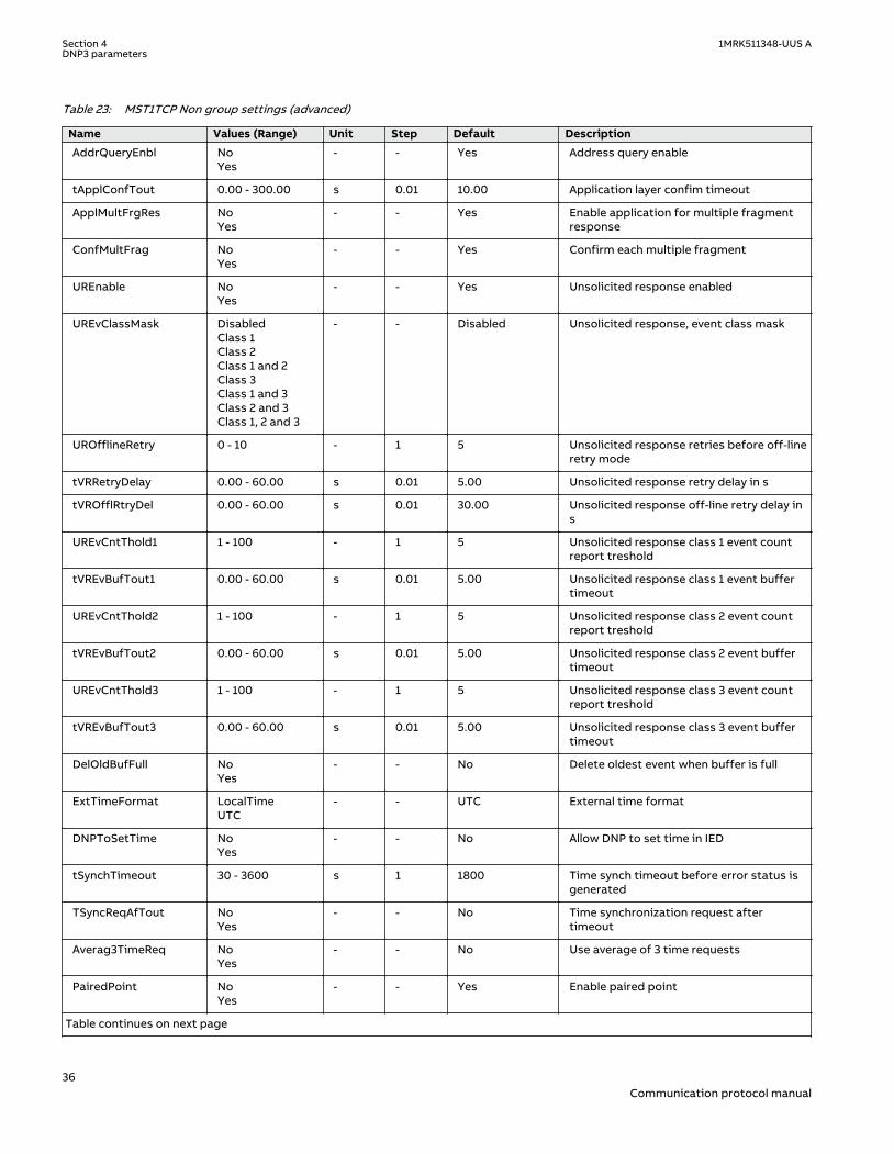
Table 23: MST1TCP Non group settings (advanced)
Name Values (Range) Unit Step Default Description
AddrQueryEnbl NoYes
- - Yes Address query enable
tApplConfTout 0.00 - 300.00 s 0.01 10.00 Application layer confim timeout
ApplMultFrgRes NoYes
- - Yes Enable application for multiple fragmentresponse
ConfMultFrag NoYes
- - Yes Confirm each multiple fragment
UREnable NoYes
- - Yes Unsolicited response enabled
UREvClassMask DisabledClass 1Class 2Class 1 and 2Class 3Class 1 and 3Class 2 and 3Class 1, 2 and 3
- - Disabled Unsolicited response, event class mask
UROfflineRetry 0 - 10 - 1 5 Unsolicited response retries before off-lineretry mode
tVRRetryDelay 0.00 - 60.00 s 0.01 5.00 Unsolicited response retry delay in s
tVROfflRtryDel 0.00 - 60.00 s 0.01 30.00 Unsolicited response off-line retry delay ins
UREvCntThold1 1 - 100 - 1 5 Unsolicited response class 1 event countreport treshold
tVREvBufTout1 0.00 - 60.00 s 0.01 5.00 Unsolicited response class 1 event buffertimeout
UREvCntThold2 1 - 100 - 1 5 Unsolicited response class 2 event countreport treshold
tVREvBufTout2 0.00 - 60.00 s 0.01 5.00 Unsolicited response class 2 event buffertimeout
UREvCntThold3 1 - 100 - 1 5 Unsolicited response class 3 event countreport treshold
tVREvBufTout3 0.00 - 60.00 s 0.01 5.00 Unsolicited response class 3 event buffertimeout
DelOldBufFull NoYes
- - No Delete oldest event when buffer is full
ExtTimeFormat LocalTimeUTC
- - UTC External time format
DNPToSetTime NoYes
- - No Allow DNP to set time in IED
tSynchTimeout 30 - 3600 s 1 1800 Time synch timeout before error status isgenerated
TSyncReqAfTout NoYes
- - No Time synchronization request aftertimeout
Averag3TimeReq NoYes
- - No Use average of 3 time requests
PairedPoint NoYes
- - Yes Enable paired point
Table continues on next page
Section 4 1MRK511348-UUS ADNP3 parameters
36Communication protocol manual

Name Values (Range) Unit Step Default Description
tSelectTimeout 1.0 - 60.0 s 0.1 30.0 Select timeout
tBrokenConTout 0 - 3600 s 1 0 Broken connection timeout
tKeepAliveT 0 - 3600 s 1 10 Keep-Alive timer
PID-4135-SETTINGS v6
Table 24: MST2TCP Non group settings (basic)
Name Values (Range) Unit Step Default Description
Operation DisabledEnabled
- - Disabled Operation Disabled/Enabled
SlaveAddress 0 - 65519 - 1 1 Slave address
MasterAddres 0 - 65519 - 1 1 Master address
ValMasterAddr NoYes
- - Yes Validate source (master) address
MasterIP-Addr 0 - 18 IPAddress
1 0.0.0.0 Master IP-address
MasterIPNetMsk 0 - 18 IPAddress
1 255.255.255.255 Master IP net mask
Obj1DefVar 1:BISingleBit2:BIWithStatus
- - 1:BISingleBit Object 1, default variation
Obj2DefVar 1:BIChWithoutTime2:BIChWithTime3:BIChWithRelTime
- - 3:BIChWithRelTime
Object 2, default variation
Obj3DefVar 1:DIWithoutFlag2:DIWithFlag
- - 1:DIWithoutFlag Object 3, default variation
Obj4DefVar 1:DIChWithoutTime2:DIChWithTime3:DIChWithRelTime
- - 3:DIChWithRelTime
Object 4, default variation
Obj10DefVar 1:BO2:BOStatus
- - 2:BOStatus Object 10, default variation
Obj20DefVar 1:BinCnt322:BinCnt165:BinCnt32WoutF6:BinCnt16WoutF
- - 5:BinCnt32WoutF Object 20, default variation
Table continues on next page
1MRK511348-UUS A Section 4DNP3 parameters
37Communication protocol manual

Name Values (Range) Unit Step Default Description
Obj22DefVar 1:BinCnt32EvWoutT2:BinCnt16EvWoutT5:BinCnt32EvWithT6:BinCnt16EvWithT
- - 1:BinCnt32EvWoutT
Object 22, default variation
Obj30DefVar 1:AI32Int2:AI16Int3:AI32IntWithoutF4:AI16IntWithoutF5:AI32FltWithF6:AI64FltWithF
- - 3:AI32IntWithoutF
Object 30, default variation
Obj32DefVar 1:AI32IntEvWoutF2:AI16IntEvWoutF3:AI32IntEvWithFT4:AI16IntEvWithFT5:AI32FltEvWithF6:AI64FltEvWithF7:AI32FltEvWithFT8:AI64FltEvWithFT
- - 1:AI32IntEvWoutF Object 32, default variation
Table 25: MST2TCP Non group settings (advanced)
Name Values (Range) Unit Step Default Description
AddrQueryEnbl NoYes
- - Yes Address query enable
tApplConfTout 0.00 - 300.00 s 0.01 10.00 Application layer confim timeout
ApplMultFrgRes NoYes
- - Yes Enable application for multiple fragmentresponse
ConfMultFrag NoYes
- - Yes Confirm each multiple fragment
UREnable NoYes
- - Yes Unsolicited response enabled
UREvClassMask DisabledClass 1Class 2Class 1 and 2Class 3Class 1 and 3Class 2 and 3Class 1, 2 and 3
- - Disabled Unsolicited response, event class mask
UROfflineRetry 0 - 10 - 1 5 Unsolicited response retries before off-lineretry mode
tVRRetryDelay 0.00 - 60.00 s 0.01 5.00 Unsolicited response retry delay in s
tVROfflRtryDel 0.00 - 60.00 s 0.01 30.00 Unsolicited response off-line retry delay ins
UREvCntThold1 1 - 100 - 1 5 Unsolicited response class 1 event countreport treshold
tVREvBufTout1 0.00 - 60.00 s 0.01 5.00 Unsolicited response class 1 event buffertimeout
Table continues on next page
Section 4 1MRK511348-UUS ADNP3 parameters
38Communication protocol manual

Name Values (Range) Unit Step Default Description
UREvCntThold2 1 - 100 - 1 5 Unsolicited response class 2 event countreport treshold
tVREvBufTout2 0.00 - 60.00 s 0.01 5.00 Unsolicited response class 2 event buffertimeout
UREvCntThold3 1 - 100 - 1 5 Unsolicited response class 3 event countreport treshold
tVREvBufTout3 0.00 - 60.00 s 0.01 5.00 Unsolicited response class 3 event buffertimeout
DelOldBufFull NoYes
- - No Delete oldest event when buffer is full
ExtTimeFormat LocalTimeUTC
- - UTC External time format
DNPToSetTime NoYes
- - No Allow DNP to set time in IED
tSynchTimeout 30 - 3600 s 1 1800 Time synch timeout before error status isgenerated
TSyncReqAfTout NoYes
- - No Time synchronization request aftertimeout
Averag3TimeReq NoYes
- - No Use average of 3 time requests
PairedPoint NoYes
- - Yes Enable paired point
tSelectTimeout 1.0 - 60.0 s 0.1 30.0 Select timeout
tBrokenConTout 0 - 3600 s 1 0 Broken connection timeout
tKeepAliveT 0 - 3600 s 1 10 Keep-Alive timer
PID-4136-SETTINGS v6
Table 26: MST3TCP Non group settings (basic)
Name Values (Range) Unit Step Default Description
Operation DisabledEnabled
- - Disabled Operation Disabled/Enabled
SlaveAddress 0 - 65519 - 1 1 Slave address
MasterAddres 0 - 65519 - 1 1 Master address
ValMasterAddr NoYes
- - Yes Validate source (master) address
MasterIP-Addr 0 - 18 IPAddress
1 0.0.0.0 Master IP-address
MasterIPNetMsk 0 - 18 IPAddress
1 255.255.255.255 Master IP net mask
Obj1DefVar 1:BISingleBit2:BIWithStatus
- - 1:BISingleBit Object 1, default variation
Obj2DefVar 1:BIChWithoutTime2:BIChWithTime3:BIChWithRelTime
- - 3:BIChWithRelTime
Object 2, default variation
Table continues on next page
1MRK511348-UUS A Section 4DNP3 parameters
39Communication protocol manual

Name Values (Range) Unit Step Default Description
Obj3DefVar 1:DIWithoutFlag2:DIWithFlag
- - 1:DIWithoutFlag Object 3, default variation
Obj4DefVar 1:DIChWithoutTime2:DIChWithTime3:DIChWithRelTime
- - 3:DIChWithRelTime
Object 4, default variation
Obj10DefVar 1:BO2:BOStatus
- - 2:BOStatus Object 10, default variation
Obj20DefVar 1:BinCnt322:BinCnt165:BinCnt32WoutF6:BinCnt16WoutF
- - 5:BinCnt32WoutF Object 20, default variation
Obj22DefVar 1:BinCnt32EvWoutT2:BinCnt16EvWoutT5:BinCnt32EvWithT6:BinCnt16EvWithT
- - 1:BinCnt32EvWoutT
Object 22, default variation
Obj30DefVar 1:AI32Int2:AI16Int3:AI32IntWithoutF4:AI16IntWithoutF5:AI32FltWithF6:AI64FltWithF
- - 3:AI32IntWithoutF
Object 30, default variation
Obj32DefVar 1:AI32IntEvWoutF2:AI16IntEvWoutF3:AI32IntEvWithFT4:AI16IntEvWithFT5:AI32FltEvWithF6:AI64FltEvWithF7:AI32FltEvWithFT8:AI64FltEvWithFT
- - 1:AI32IntEvWoutF Object 32, default variation
Table 27: MST3TCP Non group settings (advanced)
Name Values (Range) Unit Step Default Description
AddrQueryEnbl NoYes
- - Yes Address query enable
tApplConfTout 0.00 - 300.00 s 0.01 10.00 Application layer confim timeout
ApplMultFrgRes NoYes
- - Yes Enable application for multiple fragmentresponse
ConfMultFrag NoYes
- - Yes Confirm each multiple fragment
UREnable NoYes
- - Yes Unsolicited response enabled
Table continues on next page
Section 4 1MRK511348-UUS ADNP3 parameters
40Communication protocol manual
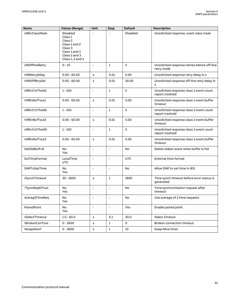
Name Values (Range) Unit Step Default Description
UREvClassMask DisabledClass 1Class 2Class 1 and 2Class 3Class 1 and 3Class 2 and 3Class 1, 2 and 3
- - Disabled Unsolicited response, event class mask
UROfflineRetry 0 - 10 - 1 5 Unsolicited response retries before off-lineretry mode
tVRRetryDelay 0.00 - 60.00 s 0.01 5.00 Unsolicited response retry delay in s
tVROfflRtryDel 0.00 - 60.00 s 0.01 30.00 Unsolicited response off-line retry delay ins
UREvCntThold1 1 - 100 - 1 5 Unsolicited response class 1 event countreport treshold
tVREvBufTout1 0.00 - 60.00 s 0.01 5.00 Unsolicited response class 1 event buffertimeout
UREvCntThold2 1 - 100 - 1 5 Unsolicited response class 2 event countreport treshold
tVREvBufTout2 0.00 - 60.00 s 0.01 5.00 Unsolicited response class 2 event buffertimeout
UREvCntThold3 1 - 100 - 1 5 Unsolicited response class 3 event countreport treshold
tVREvBufTout3 0.00 - 60.00 s 0.01 5.00 Unsolicited response class 3 event buffertimeout
DelOldBufFull NoYes
- - No Delete oldest event when buffer is full
ExtTimeFormat LocalTimeUTC
- - UTC External time format
DNPToSetTime NoYes
- - No Allow DNP to set time in IED
tSynchTimeout 30 - 3600 s 1 1800 Time synch timeout before error status isgenerated
TSyncReqAfTout NoYes
- - No Time synchronization request aftertimeout
Averag3TimeReq NoYes
- - No Use average of 3 time requests
PairedPoint NoYes
- - Yes Enable paired point
tSelectTimeout 1.0 - 60.0 s 0.1 30.0 Select timeout
tBrokenConTout 0 - 3600 s 1 0 Broken connection timeout
tKeepAliveT 0 - 3600 s 1 10 Keep-Alive timer
1MRK511348-UUS A Section 4DNP3 parameters
41Communication protocol manual

PID-4137-SETTINGS v6
Table 28: MST4TCP Non group settings (basic)
Name Values (Range) Unit Step Default Description
Operation DisabledEnabled
- - Disabled Operation Disabled/Enabled
SlaveAddress 0 - 65519 - 1 1 Slave address
MasterAddres 0 - 65519 - 1 1 Master address
ValMasterAddr NoYes
- - Yes Validate source (master) address
MasterIP-Addr 0 - 18 IPAddress
1 0.0.0.0 Master IP-address
MasterIPNetMsk 0 - 18 IPAddress
1 255.255.255.255 Master IP net mask
Obj1DefVar 1:BISingleBit2:BIWithStatus
- - 1:BISingleBit Object 1, default variation
Obj2DefVar 1:BIChWithoutTime2:BIChWithTime3:BIChWithRelTime
- - 3:BIChWithRelTime
Object 2, default variation
Obj3DefVar 1:DIWithoutFlag2:DIWithFlag
- - 1:DIWithoutFlag Object 3, default variation
Obj4DefVar 1:DIChWithoutTime2:DIChWithTime3:DIChWithRelTime
- - 3:DIChWithRelTime
Object 4, default variation
Obj10DefVar 1:BO2:BOStatus
- - 2:BOStatus Object 10, default variation
Obj20DefVar 1:BinCnt322:BinCnt165:BinCnt32WoutF6:BinCnt16WoutF
- - 5:BinCnt32WoutF Object 20, default variation
Table continues on next page
Section 4 1MRK511348-UUS ADNP3 parameters
42Communication protocol manual
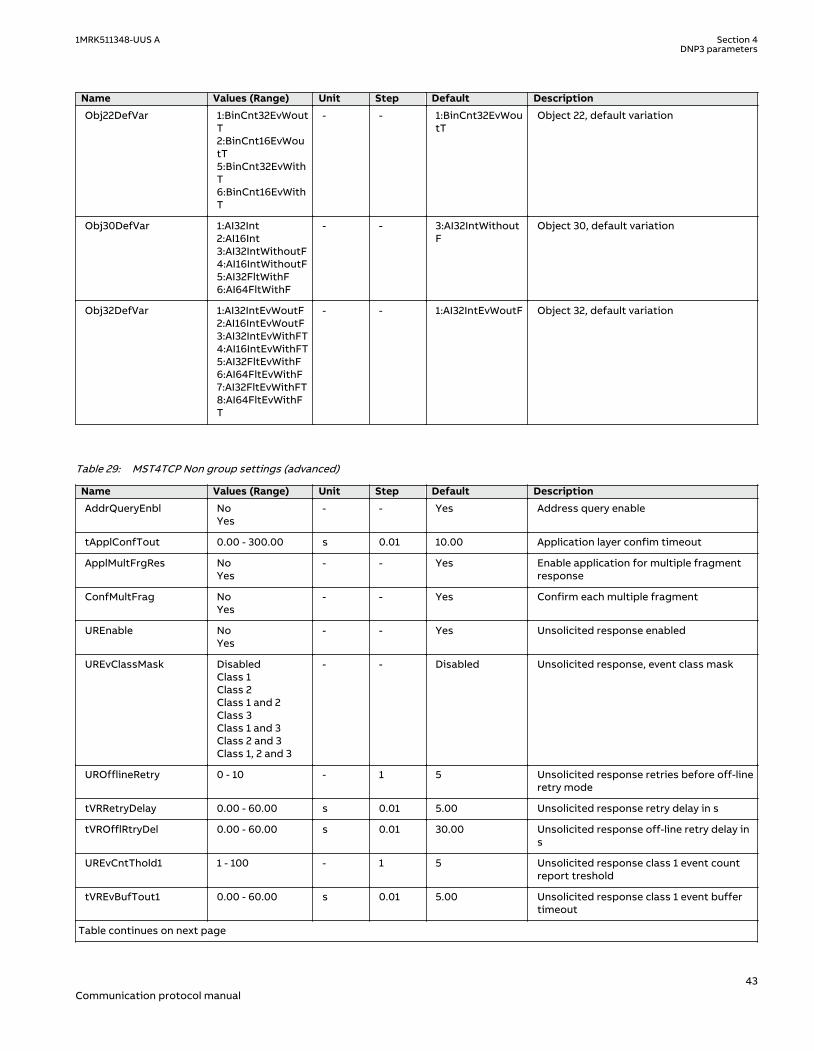
Name Values (Range) Unit Step Default Description
Obj22DefVar 1:BinCnt32EvWoutT2:BinCnt16EvWoutT5:BinCnt32EvWithT6:BinCnt16EvWithT
- - 1:BinCnt32EvWoutT
Object 22, default variation
Obj30DefVar 1:AI32Int2:AI16Int3:AI32IntWithoutF4:AI16IntWithoutF5:AI32FltWithF6:AI64FltWithF
- - 3:AI32IntWithoutF
Object 30, default variation
Obj32DefVar 1:AI32IntEvWoutF2:AI16IntEvWoutF3:AI32IntEvWithFT4:AI16IntEvWithFT5:AI32FltEvWithF6:AI64FltEvWithF7:AI32FltEvWithFT8:AI64FltEvWithFT
- - 1:AI32IntEvWoutF Object 32, default variation
Table 29: MST4TCP Non group settings (advanced)
Name Values (Range) Unit Step Default Description
AddrQueryEnbl NoYes
- - Yes Address query enable
tApplConfTout 0.00 - 300.00 s 0.01 10.00 Application layer confim timeout
ApplMultFrgRes NoYes
- - Yes Enable application for multiple fragmentresponse
ConfMultFrag NoYes
- - Yes Confirm each multiple fragment
UREnable NoYes
- - Yes Unsolicited response enabled
UREvClassMask DisabledClass 1Class 2Class 1 and 2Class 3Class 1 and 3Class 2 and 3Class 1, 2 and 3
- - Disabled Unsolicited response, event class mask
UROfflineRetry 0 - 10 - 1 5 Unsolicited response retries before off-lineretry mode
tVRRetryDelay 0.00 - 60.00 s 0.01 5.00 Unsolicited response retry delay in s
tVROfflRtryDel 0.00 - 60.00 s 0.01 30.00 Unsolicited response off-line retry delay ins
UREvCntThold1 1 - 100 - 1 5 Unsolicited response class 1 event countreport treshold
tVREvBufTout1 0.00 - 60.00 s 0.01 5.00 Unsolicited response class 1 event buffertimeout
Table continues on next page
1MRK511348-UUS A Section 4DNP3 parameters
43Communication protocol manual

Name Values (Range) Unit Step Default Description
UREvCntThold2 1 - 100 - 1 5 Unsolicited response class 2 event countreport treshold
tVREvBufTout2 0.00 - 60.00 s 0.01 5.00 Unsolicited response class 2 event buffertimeout
UREvCntThold3 1 - 100 - 1 5 Unsolicited response class 3 event countreport treshold
tVREvBufTout3 0.00 - 60.00 s 0.01 5.00 Unsolicited response class 3 event buffertimeout
DelOldBufFull NoYes
- - No Delete oldest event when buffer is full
ExtTimeFormat LocalTimeUTC
- - UTC External time format
DNPToSetTime NoYes
- - No Allow DNP to set time in IED
tSynchTimeout 30 - 3600 s 1 1800 Time synch timeout before error status isgenerated
TSyncReqAfTout NoYes
- - No Time synchronization request aftertimeout
Averag3TimeReq NoYes
- - No Use average of 3 time requests
PairedPoint NoYes
- - Yes Enable paired point
tSelectTimeout 1.0 - 60.0 s 0.1 30.0 Select timeout
tBrokenConTout 0 - 3600 s 1 0 Broken connection timeout
tKeepAliveT 0 - 3600 s 1 10 Keep-Alive timer
Section 4 1MRK511348-UUS ADNP3 parameters
44Communication protocol manual

Section 5 Glossary
5.1 GlossaryM14893-1 v18
AC Alternating current
ACC Actual channel
ACT Application configuration tool within PCM600
A/D converter Analog-to-digital converter
ADBS Amplitude deadband supervision
ADM Analog digital conversion module, with time synchronization
AI Analog input
ANSI American National Standards Institute
AR Autoreclosing
ASCT Auxiliary summation current transformer
ASD Adaptive signal detection
ASDU Application service data unit
AWG American Wire Gauge standard
BBP Busbar protection
BFOC/2,5 Bayonet fiber optic connector
BFP Breaker failure protection
BI Binary input
BIM Binary input module
BOM Binary output module
BOS Binary outputs status
BR External bistable relay
BS British Standards
BSR Binary signal transfer function, receiver blocks
BST Binary signal transfer function, transmit blocks
C37.94 IEEE/ANSI protocol used when sending binary signals between IEDs
CAN Controller Area Network. ISO standard (ISO 11898) for serialcommunication
CB Circuit breaker
CBM Combined backplane module
CCITT Consultative Committee for International Telegraph and Telephony. AUnited Nations-sponsored standards body within the InternationalTelecommunications Union.
1MRK511348-UUS A Section 5Glossary
45Communication protocol manual
CCM CAN carrier module
CCVT Capacitive Coupled Voltage Transformer
Class C Protection Current Transformer class as per IEEE/ ANSI
CMPPS Combined megapulses per second
CMT Communication Management tool in PCM600
CO cycle Close-open cycle
Codirectional Way of transmitting G.703 over a balanced line. Involves two twisted pairsmaking it possible to transmit information in both directions
COM Command
COMTRADE Standard Common Format for Transient Data Exchange format forDisturbance recorder according to IEEE/ANSI C37.111, 1999 / IEC 60255-24
Contra-directional Way of transmitting G.703 over a balanced line. Involves four twisted pairs,two of which are used for transmitting data in both directions and two fortransmitting clock signals
COT Cause of transmission
CPU Central processing unit
CR Carrier receive
CRC Cyclic redundancy check
CROB Control relay output block
CS Carrier send
CT Current transformer
CU Communication unit
CVT or CCVT Capacitive voltage transformer
DAR Delayed autoreclosing
DARPA Defense Advanced Research Projects Agency (The US developer of theTCP/IP protocol etc.)
DBDL Dead bus dead line
DBLL Dead bus live line
DC Direct current
DFC Data flow control
DFT Discrete Fourier transform
DHCP Dynamic Host Configuration Protocol
DIP-switch Small switch mounted on a printed circuit board
DI Digital input
DLLB Dead line live bus
DNP Distributed Network Protocol as per IEEE Std 1815-2012
DR Disturbance recorder
DRAM Dynamic random access memory
DRH Disturbance report handler
Section 5 1MRK511348-UUS AGlossary
46Communication protocol manual

DSP Digital signal processor
DTT Direct transfer trip scheme
ECT Ethernet configuration tool
EHV network Extra high voltage network
EIA Electronic Industries Association
EMC Electromagnetic compatibility
EMF Electromotive force
EMI Electromagnetic interference
EnFP End fault protection
EPA Enhanced performance architecture
ESD Electrostatic discharge
F-SMA Type of optical fiber connector
FAN Fault number
FCB Flow control bit; Frame count bit
FOX 20 Modular 20 channel telecommunication system for speech, data andprotection signals
FOX 512/515 Access multiplexer
FOX 6Plus Compact time-division multiplexer for the transmission of up to sevenduplex channels of digital data over optical fibers
FPN Flexible product naming
FTP File Transfer Protocol
FUN Function type
G.703 Electrical and functional description for digital lines used by localtelephone companies. Can be transported over balanced and unbalancedlines
GCM Communication interface module with carrier of GPS receiver module
GDE Graphical display editor within PCM600
GI General interrogation command
GIS Gas-insulated switchgear
GOOSE Generic object-oriented substation event
GPS Global positioning system
GSAL Generic security application
GSE Generic substation event
HDLC protocol High-level data link control, protocol based on the HDLC standard
HFBR connector type Plastic fiber connector
HLV circuit Hazardous Live Voltage according to IEC60255-27
HMI Human-machine interface
HSAR High speed autoreclosing
HSR High-availability Seamless Redundancy
1MRK511348-UUS A Section 5Glossary
47Communication protocol manual

HV High-voltage
HVDC High-voltage direct current
IDBS Integrating deadband supervision
IEC International Electrical Committee
IEC 60044-6 IEC Standard, Instrument transformers – Part 6: Requirements forprotective current transformers for transient performance
IEC 60870-5-103 Communication standard for protection equipment. A serial master/slaveprotocol for point-to-point communication
IEC 61850 Substation automation communication standard
IEC 61850–8–1 Communication protocol standard
IEEE Institute of Electrical and Electronics Engineers
IEEE 802.12 A network technology standard that provides 100 Mbits/s on twisted-pairor optical fiber cable
IEEE P1386.1 PCI Mezzanine Card (PMC) standard for local bus modules. References theCMC (IEEE P1386, also known as Common Mezzanine Card) standard forthe mechanics and the PCI specifications from the PCI SIG (Special InterestGroup) for the electrical EMF (Electromotive force).
IEEE 1686 Standard for Substation Intelligent Electronic Devices (IEDs) Cyber SecurityCapabilities
IED Intelligent electronic device
IET600 Integrated engineering tool
I-GIS Intelligent gas-insulated switchgear
IOM Binary input/output module
Instance When several occurrences of the same function are available in the IED,they are referred to as instances of that function. One instance of afunction is identical to another of the same kind but has a differentnumber in the IED user interfaces. The word "instance" is sometimesdefined as an item of information that is representative of a type. In thesame way an instance of a function in the IED is representative of a type offunction.
IP 1. Internet protocol. The network layer for the TCP/IP protocol suite widelyused on Ethernet networks. IP is a connectionless, best-effort packet-switching protocol. It provides packet routing, fragmentation andreassembly through the data link layer.2. Ingression protection, according to IEC 60529
IP 20 Ingression protection, according to IEC 60529, levelIP20- Protected against solid foreign objects of 12.5mm diameter andgreater.
IP 40 Ingression protection, according to IEC 60529, level IP40-Protected againstsolid foreign objects of 1mm diameter and greater.
IP 54 Ingression protection, according to IEC 60529, levelIP54-Dust-protected, protected against splashing water.
IRF Internal failure signal
IRIG-B: InterRange Instrumentation Group Time code format B, standard 200
Section 5 1MRK511348-UUS AGlossary
48Communication protocol manual

ITU International Telecommunications Union
LAN Local area network
LIB 520 High-voltage software module
LCD Liquid crystal display
LDCM Line data communication module
LDD Local detection device
LNT LON network tool
LON Local operating network
MCB Miniature circuit breaker
MCM Mezzanine carrier module
MIM Milli-ampere module
MPM Main processing module
MVAL Value of measurement
MVB Multifunction vehicle bus. Standardized serial bus originally developed foruse in trains.
NCC National Control Centre
NOF Number of grid faults
NUM Numerical module
OCO cycle Open-close-open cycle
OCP Overcurrent protection
OEM Optical Ethernet module
OLTC On-load tap changer
OTEV Disturbance data recording initiated by other event than start/pick-up
OV Overvoltage
Overreach A term used to describe how the relay behaves during a fault condition. Forexample, a distance relay is overreaching when the impedance presentedto it is smaller than the apparent impedance to the fault applied to thebalance point, that is, the set reach. The relay “sees” the fault but perhapsit should not have seen it.
PCI Peripheral component interconnect, a local data bus
PCM Pulse code modulation
PCM600 Protection and control IED manager
PC-MIP Mezzanine card standard
PELV circuit Protected Extra-Low Voltage circuit type according to IEC60255-27
PMC PCI Mezzanine card
POR Permissive overreach
POTT Permissive overreach transfer trip
Process bus Bus or LAN used at the process level, that is, in near proximity to themeasured and/or controlled components
1MRK511348-UUS A Section 5Glossary
49Communication protocol manual

PRP Parallel redundancy protocol
PSM Power supply module
PST Parameter setting tool within PCM600
PTP Precision time protocol
PT ratio Potential transformer or voltage transformer ratio
PUTT Permissive underreach transfer trip
RASC Synchrocheck relay, COMBIFLEX
RCA Relay characteristic angle
RISC Reduced instruction set computer
RMS value Root mean square value
RS422 A balanced serial interface for the transmission of digital data in point-to-point connections
RS485 Serial link according to EIA standard RS485
RTC Real-time clock
RTU Remote terminal unit
SA Substation Automation
SBO Select-before-operate
SC Switch or push button to close
SCL Short circuit location
SCS Station control system
SCADA Supervision, control and data acquisition
SCT System configuration tool according to standard IEC 61850
SDU Service data unit
SELV circuit Safety Extra-Low Voltage circuit type according to IEC60255-27
SFP Small form-factor pluggable (abbreviation)Optical Ethernet port (explanation)
SLM Serial communication module.
SMA connector Subminiature version A, A threaded connector with constant impedance.
SMT Signal matrix tool within PCM600
SMS Station monitoring system
SNTP Simple network time protocol – is used to synchronize computer clocks onlocal area networks. This reduces the requirement to have accuratehardware clocks in every embedded system in a network. Each embeddednode can instead synchronize with a remote clock, providing the requiredaccuracy.
SOF Status of fault
SPA Strömberg Protection Acquisition (SPA), a serial master/slave protocol forpoint-to-point and ring communication.
SRY Switch for CB ready condition
Section 5 1MRK511348-UUS AGlossary
50Communication protocol manual

ST Switch or push button to trip
Starpoint Neutral/Wye point of transformer or generator
SVC Static VAr compensation
TC Trip coil
TCS Trip circuit supervision
TCP Transmission control protocol. The most common transport layer protocolused on Ethernet and the Internet.
TCP/IP Transmission control protocol over Internet Protocol. The de factostandard Ethernet protocols incorporated into 4.2BSD Unix. TCP/IP wasdeveloped by DARPA for Internet working and encompasses both networklayer and transport layer protocols. While TCP and IP specify two protocolsat specific protocol layers, TCP/IP is often used to refer to the entire USDepartment of Defense protocol suite based upon these, including Telnet,FTP, UDP and RDP.
TEF Time delayed gound-fault protection function
TLS Transport Layer Security
TM Transmit (disturbance data)
TNC connector Threaded Neill-Concelman, a threaded constant impedance version of aBNC connector
TP Trip (recorded fault)
TPZ, TPY, TPX, TPS Current transformer class according to IEC
TRM Transformer Module. This module transforms currents and voltages takenfrom the process into levels suitable for further signal processing.
TYP Type identification
UMT User management tool
Underreach A term used to describe how the relay behaves during a fault condition. Forexample, a distance relay is underreaching when the impedance presentedto it is greater than the apparent impedance to the fault applied to thebalance point, that is, the set reach. The relay does not “see” the fault butperhaps it should have seen it. See also Overreach.
UTC Coordinated Universal Time. A coordinated time scale, maintained by theBureau International des Poids et Mesures (BIPM), which forms the basis ofa coordinated dissemination of standard frequencies and time signals.UTC is derived from International Atomic Time (TAI) by the addition of awhole number of "leap seconds" to synchronize it with Universal Time 1(UT1), thus allowing for the eccentricity of the Earth's orbit, the rotationalaxis tilt (23.5 degrees), but still showing the Earth's irregular rotation, onwhich UT1 is based. The Coordinated Universal Time is expressed using a24-hour clock, and uses the Gregorian calendar. It is used for aeroplane andship navigation, where it is also sometimes known by the military name,"Zulu time." "Zulu" in the phonetic alphabet stands for "Z", which stands forlongitude zero.
UV Undervoltage
WEI Weak end infeed logic
VT Voltage transformer
1MRK511348-UUS A Section 5Glossary
51Communication protocol manual

X.21 A digital signalling interface primarily used for telecom equipment
3IO Three times zero-sequence current.Often referred to as the residual or theground-fault current
3VO Three times the zero sequence voltage. Often referred to as the residualvoltage or the neutral point voltage
Section 5 1MRK511348-UUS AGlossary
52Communication protocol manual

53

ABB ABSubstation Automation ProductsSE-721 59 Västerås, SwedenPhone +46 (0) 21 32 50 00
www.abb.com/substationautomation
© Copyright 2016 ABB.All rights reserved.
Scan this QR code to visit our website1M
RK
5113
48-
UU
S