compact integration of cryogenic lna on miniature cryocooler · low noise amplifier (lna), is...
TRANSCRIPT
P#
088
1
Compact Integration of Cryogenic LNA
on Miniature Cryocooler
J. Delmas, R.J. Webber, I.V. Vernik,
G. Prokopenko and D. Gupta
Hypres, Inc., Elmsford, NY, USA 10523
ABSTRACT
Cryogenic low-noise amplifiers (LNAs) have been used in radio astronomy for some time, in
particular as the first stage of receivers at microwave frequencies and more recently in IF sections
following mixers at millimeter-wave and sub-millimeter-wave frequencies.
For some of these applications, the cryogenic LNA is mounted onto a cryocooler. However,
compactness and energy efficiency of the whole system are seldom a major requirement. Two-stage
coolers are thus widely used as they provide both low temperature and significant cooling power,
necessary to cool down a low-loss input line in order to minimize the receiver noise temperature.
HYPRES is currently developing an approach for an all cryogenic receiver, comprising a split
architecture. This configuration detaches the analog radio frequency (RF) components in front of
the analog-to-digital converter and houses it in a much smaller module, cooled by a single-stage
cryocooler that allows placement close to the antenna; the rest of the components are left in a larger
module including a two-stage 4K cooler.
In this study we focus on the front-end module and examine the integration of a 20 GHz cryo-
genic LNA with a miniature single-stage Stirling cryocooler. The objective of this cryogenic pack-
aging is to optimize the technical characteristics of the LNA such as gain, linearity and noise tem-
perature, as well as the size, weight and power of the system. We discuss different solutions studied
for the input and output RF lines, both in terms of electrical performance and heat load, and de-
scribe the different technological choices adopted to comply with strict size requirements. Finally,
we present preliminary RF measurements of the final system.
INTRODUCTION
HYPRES has been successfully integrating superconducting Integrated Circuits (ICs) into dif-
ferent 4 Kelvin cryocoolers for quite some time. This includes both digital receiver systems [2 to 6],
and Voltage Standard chips [9,10]. More recently, some effort has been put into integrating sys-
tems, superconducting or not, with miniature cryocoolers. These small coolers are mainly targeted
at the market of increasingly sophisticated portable cryocooled infrared imagers that are developed
for a variety of applications, including surveillance, reconnaissance, and navigation. Most of the
miniature compact cryocoolers are based on either rotary Stirling of Linear Split Stirling principles
and are readily available. The performance of these systems, for which size, weight and power are
critical, is extremely attractive for a variety of applications.
565Cryocoolers 17, edited by S.D. Miller and R.G. Ross, Jr.©¶International Cryocooler Conference, Inc., Boulder, CO, 2012
P#
088
2
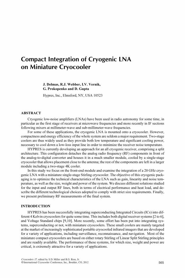
Figure 1. The “Split” receiver architecture detaches the analog RF front-end as a separate module.
Motivation
The system described in this paper originally comes from the need for a “split architecture” for
an all-digital receiver. The principle of a compact cryogenic amplifier can however be applied to
many different applications at various frequencies, such as MRI or instrumentation.
Superconductor analog-to-digital converter (ADC) technology enables direct digitization of
RF waveforms with high linearity and opens up new architectures for increasing spectrum effi-
ciency. Direct digitization, followed by distribution and processing of RF signals in the digital
domain, facilitates superior monitoring, control and utilization of the RF spectrum as well as en-
ables advanced communication concepts involving multiple frequency bands and multiple polar-
izations. In addition to this primary benefit, a secondary benefit of using superconductor ADCs,
which require cooling to very low (4 K) temperatures, is in lowering the receiver noise temperature.
Applications, such as satellite communications, where the antenna noise temperature is low, are
excellent candidates for such cryogenic receivers [1].
Typically, in addition to the 4-K stage, a cryocooled superconductor digital-RF receiver system
includes one or more intermediate (e.g. 40 K) temperature stages, often with excess cooling capac-
ity. This additional temperature stage has been used in these systems to host analog RF compo-
nents, such as a high-temperature superconductor (HTS) filter, and optionally a low-noise amplifier
(LNA). Using commercial 4-K cryocoolers, several such rack-mounted systems have been devel-
oped [2 to 5]. These are suitable for large satellite ground stations.
However, the space under the dish is quite limited for smaller terminals and calls for a different
configuration. Ideally, signal digitization at RF should occur as close to the antenna as possible.
However, depending on the space and power dissipation constraints, it may not be possible to place
a complete receiver unit at or near the location of the antenna. A 77-K single-stage cryocooler
system requires much less space and power than a 4-K multi-stage cryocooler. Therefore, the sys-
tem is split in two parts and a small cryocooled analog RF unit, comprising a wideband filter and
low noise amplifier (LNA), is placed near the antenna and the larger unit, linked via optical fiber, is
placed at a distance where more space is available (Figure 1). In the case of satellite communica-
tion on a shipboard platform, this smaller cryogenic analog RF module (CARM) would be placed
right behind the dish and the digitizer would be placed below deck. A similar configuration, split-
ting the system into two parts also works for commercial wireless base-stations, where the larger
rack-mounted digital-RF receiver will remain on the ground while a CARM is attached to the
tower-mounted antenna. Most of the advantage of reducing the receiver noise temperature through
cooling is retained in this architecture through the use of the cooled LNA. However, the elevated
gain requirement for this cooled LNA must be carefully balanced against power consumption and
linearity.
566 CRYOCOOLER APPLICATIONS
P#
088
3In the first implementation of the CARM, two variants have been designed for the satellite
communication ground sector in Ka and X bands. These match well with the multi-band digital-RF
receivers with two superconductor analog-to-digital converters (ADCs) that digitize the X/Ka bands
directly. The first variant, not discussed here includes three analog chains, two for Ka-band right-
hand and left-hand polarizations and one for X-band. The second, smaller, variant includes a single
Ka-band chain and is cooled by a commercial-off-the-shelf 77K cryocooler. The current ver-
sions of the CARM include high-temperature superconductor (HTS) analog filters and semi-
conductor LNAs; they do not include an electrical-to-optical converter (E/O).
DESIGN OF THE SYSTEM
The most important characteristics of the system are its compactness and the ability to provide
amplification with a minimum noise temperature. Designing a compact and efficient cryopackage
is challenging both in terms of cost, reliability and technical achievement. The different heat loads,
whether they are conductive, radiative or direct through heating of the amplifier have to be carefully
assessed and controlled in order to have any hope of success. At this kind of temperature, vacuum
is also a critical parameter, as the remaining gas after the initial pump out, coming from outgassing
or virtual leaks, is not adsorbed by any cold surface as it can be in lower temperature systems and
contributes to heating the cold parts. The final design, and especially the choice of materials, is thus a
careful compromise between electrical performance, thermal conductivity, and behavior under vacuum.
General Description of the System
The heart of the system is the Low Noise Amplifier (LNA) that has to be cooled in order to get
the best performance in terms of gain and noise. It is thus desirable to have a direct thermal link
between the cooler and the amplifier, in order to get the best cooling. As it is not superconducting,
there is no threshold temperature to reach to have the system working, and the amplifier works
properly from room temperature down to its cryogenic operating temperature. However, its perfor-
mance greatly increases when cooled down. The target operating temperature is below 80¶K. Two
diodes used as thermometers (one for temperature monitoring and one for the cooler temperature
regulation feedback) are bolted onto the body of the LNA. The body of the LNA is connected to the cold
head of the cooler via a flexible highly conductive thermal link in order to accommodate for thermal
contraction of the different components while still providing an excellent cooling of the amplifier.
The output of the system is a K-type coaxial connector (also called SMA 2.92). A K-type
feedthrough is soldered on the top flange of the cryostat, and a coaxial cable is connected between
this feedthrough and the output of the LNA. As the cable is after the amplifier, RF losses are not
critical as long as they remain of the order of a few dBs.
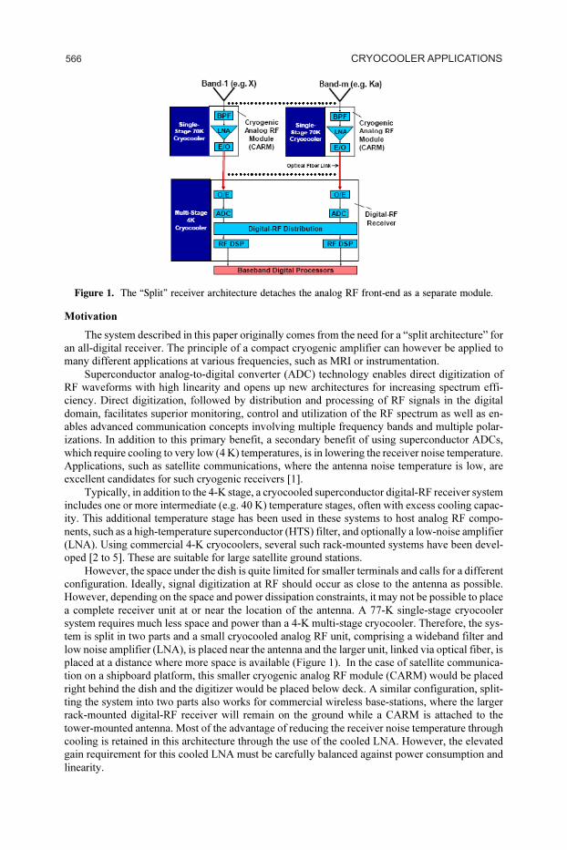
The input of the system is specified to be a square WR42 waveguide flange. Most of the ampli-
fiers we considered have a coaxial input which means that a waveguide to coaxial adapter has to be
part of the system. In terms of mechanical integration, the different choices are to do the conversion
before the vacuum feedthrough or inside the vacuum enclosure. The advantage of the first solution
is that the input vacuum feedthrough is then similar to the output, and coaxial vacuum feedthroughs
are well known and readily available. The LNA is then connected to the waveguide to coaxial
adapter via a coaxial cable. The second solution ensures the best electrical performance, as a
waveguide induces fewer losses than a coaxial cable, but the vacuum feedthrough has to be a
waveguide window that is less compact and most of the time custom made. Figure 2 shows the RF
chain of the second solution.
Heat Load and Electrical Loss Balance
The main challenge of the cryogenic integration of the system is to control both the heat load
and the electrical losses. The electrical loss depends on the electrical conductivity and generally
speaking, for metals, electrical and thermal conductivity are proportionally related. A high electri-
cal conductivity thus induces a high heat load. The most compact commercially available coolers
usually provide a cooling power between 500¶mW and 1¶W at 77¶K. The overall heat load, including
radiations, shall then be of this order of magnitude.
567INTEGRATION OF CRYOGENIC LNA ON MINIATURE COOLER
P#
088
4
Figure 2. RF chain of the system using a waveguide vacuum feedthrough; the cooler is not shown.
For the output coaxial line, as losses are not critical, a reasonable length of Be-Cu coaxes
ensures a good enough RF performance and reasonable heat load. Thermometers and amplifiers are
biased using thin phosphor-bronze twisted pairs. Although the bias current of the LNA is not neg-
ligible, it is still small enough not to induce a significant voltage drop across the twisted pair. As a
result the total heat load conducted through the output line and biasing lines is kept below 100 mW.
The input signal line is the most critical in terms of RF losses. In order to keep the overall
system noise low, the input line loss, which is in front of the amplifier, has to be minimized. We
estimated that a loss above 0.25 dB in the input line would lead to a noise level higher than the one
we targeted.
We initially considered the first option mentioned above, using a waveguide to coaxial adapter
outside of the vacuum enclosure and then a coaxial feedthrough. To ensure both a good RF perfor-
mance and a low thermal conductance, the link between the LNA and the feedthrough was made by
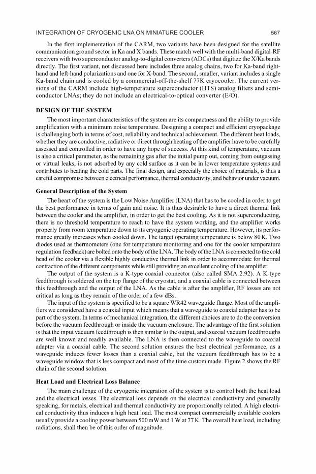
a custom coaxial cable. As the system is operating at high frequency (20 GHz), only a few skin
depths of metal are used in the signal transport, so it makes sense to remove any excess metal [8].
An off-the-shelf stainless steel coaxial cable was disassembled, plated with a few microns of gold
and then the outer conductor was thinned out in order to reduce further the heat load (see Figure 3).
The resulting heat load created by the input coaxial line is then about 170 mW. In terms of RF
loss however, the custom coaxial solution cable did not meet our requirements. The total loss (co-
axial vacuum feedthrough connected to the custom cable) was a little lower than 0.5 dB, which is
higher than needed.
The second option for a low RF loss input line is to have a waveguide vacuum feedthrough
followed by a cryogenic waveguide up to the amplifier. The main challenges for this solution are to
maintain a low heat leak through the waveguide, which is usually made of metal, and to provide a
vacuum feedthrough that is both low loss and leak tight. Waveguide vacuum feedthroughs have
been successfully built for high frequency [6,7], including by Hypres [9, 10]. The RF loss however
Figure 3. SS custom coaxial cable disassembled (left) and after machining of the outer conductor (right).
568 CRYOCOOLER APPLICATIONS
P#
088
5
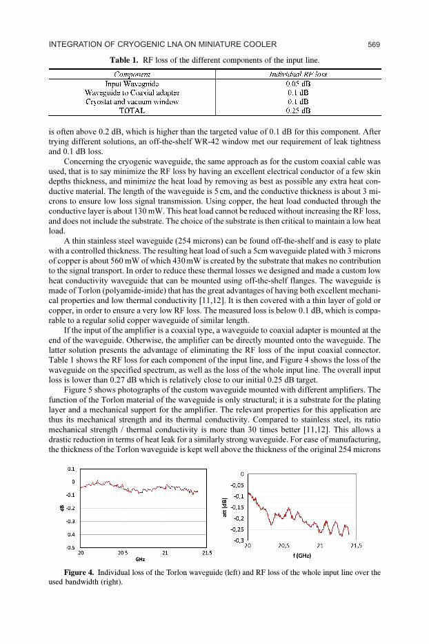
Figure 4. Individual loss of the Torlon waveguide (left) and RF loss of the whole input line over the
used bandwidth (right).
Table 1. RF loss of the different components of the input line.
is often above 0.2 dB, which is higher than the targeted value of 0.1 dB for this component. After
trying different solutions, an off-the-shelf WR-42 window met our requirement of leak tightness
and 0.1 dB loss.
Concerning the cryogenic waveguide, the same approach as for the custom coaxial cable was
used, that is to say minimize the RF loss by having an excellent electrical conductor of a few skin
depths thickness, and minimize the heat load by removing as best as possible any extra heat con-
ductive material. The length of the waveguide is 5¶cm, and the conductive thickness is about 3 mi-
crons to ensure low loss signal transmission. Using copper, the heat load conducted through the
conductive layer is about 130 mW. This heat load cannot be reduced without increasing the RF loss,
and does not include the substrate. The choice of the substrate is then critical to maintain a low heat
load.
A thin stainless steel waveguide (254 microns) can be found off-the-shelf and is easy to plate
with a controlled thickness. The resulting heat load of such a 5cm waveguide plated with 3 microns
of copper is about 560 mW of which 430¶mW is created by the substrate that makes no contribution
to the signal transport. In order to reduce these thermal losses we designed and made a custom low
heat conductivity waveguide that can be mounted using off-the-shelf flanges. The waveguide is
made of Torlon (polyamide-imide) that has the great advantages of having both excellent mechani-
cal properties and low thermal conductivity [11,12]. It is then covered with a thin layer of gold or
copper, in order to ensure a very low RF loss. The measured loss is below 0.1 dB, which is compa-
rable to a regular solid copper waveguide of similar length.
If the input of the amplifier is a coaxial type, a waveguide to coaxial adapter is mounted at the
end of the waveguide. Otherwise, the amplifier can be directly mounted onto the waveguide. The
latter solution presents the advantage of eliminating the RF loss of the input coaxial connector.
Table 1 shows the RF loss for each component of the input line, and Figure 4 shows the loss of the
waveguide on the specified spectrum, as well as the loss of the whole input line. The overall input
loss is lower than 0.27 dB which is relatively close to our initial 0.25 dB target.
Figure 5 shows photographs of the custom waveguide mounted with different amplifiers. The
function of the Torlon material of the waveguide is only structural; it is a substrate for the plating
layer and a mechanical support for the amplifier. The relevant properties for this application are
thus its mechanical strength and its thermal conductivity. Compared to stainless steel, its ratio
mechanical strength / thermal conductivity is more than 30 times better [11,12]. This allows a
drastic reduction in terms of heat leak for a similarly strong waveguide. For ease of manufacturing,
the thickness of the Torlon waveguide is kept well above the thickness of the original 254 microns
569INTEGRATION OF CRYOGENIC LNA ON MINIATURE COOLER
P#
088
6
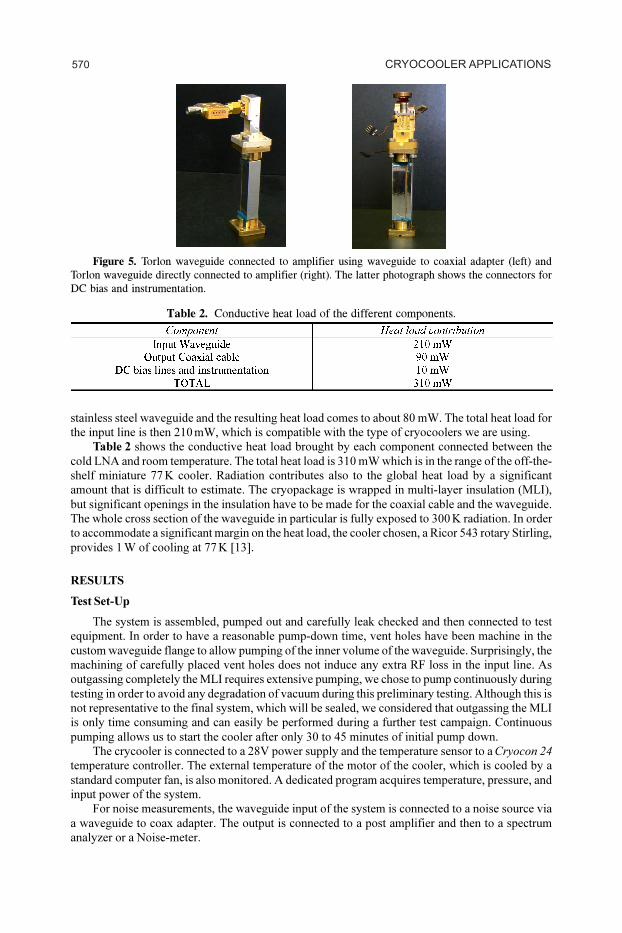
Figure 5. Torlon waveguide connected to amplifier using waveguide to coaxial adapter (left) and
Torlon waveguide directly connected to amplifier (right). The latter photograph shows the connectors for
DC bias and instrumentation.
Table 2. Conductive heat load of the different components.
stainless steel waveguide and the resulting heat load comes to about 80 mW. The total heat load for
the input line is then 210¶mW, which is compatible with the type of cryocoolers we are using.
Table 2 shows the conductive heat load brought by each component connected between the
cold LNA and room temperature. The total heat load is 310 mW which is in the range of the off-the-
shelf miniature 77¶K cooler. Radiation contributes also to the global heat load by a significant
amount that is difficult to estimate. The cryopackage is wrapped in multi-layer insulation (MLI),
but significant openings in the insulation have to be made for the coaxial cable and the waveguide.
The whole cross section of the waveguide in particular is fully exposed to 300¶K radiation. In order
to accommodate a significant margin on the heat load, the cooler chosen, a Ricor 543 rotary Stirling,
provides 1¶W of cooling at 77¶K [13].
RESULTS
Test Set-Up
The system is assembled, pumped out and carefully leak checked and then connected to test
equipment. In order to have a reasonable pump-down time, vent holes have been machine in the
custom waveguide flange to allow pumping of the inner volume of the waveguide. Surprisingly, the
machining of carefully placed vent holes does not induce any extra RF loss in the input line. As
outgassing completely the MLI requires extensive pumping, we chose to pump continuously during
testing in order to avoid any degradation of vacuum during this preliminary testing. Although this is
not representative to the final system, which will be sealed, we considered that outgassing the MLI
is only time consuming and can easily be performed during a further test campaign. Continuous
pumping allows us to start the cooler after only 30 to 45 minutes of initial pump down.
The crycooler is connected to a 28V power supply and the temperature sensor to a Cryocon 24
temperature controller. The external temperature of the motor of the cooler, which is cooled by a
standard computer fan, is also monitored. A dedicated program acquires temperature, pressure, and
input power of the system.
For noise measurements, the waveguide input of the system is connected to a noise source via
a waveguide to coax adapter. The output is connected to a post amplifier and then to a spectrum
analyzer or a Noise-meter.
570 CRYOCOOLER APPLICATIONS

P#
088
7
Figure 6. Temperature and input power of the system during cool down; the dotted line shows the
operating temperature.
Figure 7. Temperature vs Input power of the system for different configurations.
Measurement Results
As shown in Figure 6, the cool down to minimum temperature takes about 2 hours. After one
hour however, the target operating temperature (80¶K) is reached. As the temperature is not regu-
lated (the set point on the cooler feedback loop is set lower than 70¶K), the input power of the
system increases up to a value of 38.5 watts. The set point can be adjusted while the cooler is
running, allowing easy measurement of the input power vs. temperature characteristics for the same
set-up. Figure 7 shows these data graphed for different system configurations: the complete system
mounted with a waveguide type input LNA, the complete system mounted with a coaxial type input
LNA (that requires a waveguide to coaxial adapter), and the cryocooler only. In the latter configu-
ration there is no conductive heat load other than instrumentation biasing. The RF input and output
of the cryopackage however are simply disconnected from the 300¶K vacuum enclosure, so the heat
load from radiation remains the same as for the complete system mounted with a coaxial type input
LNA. In all cases, the input power is significantly larger than the specification provided by Ricor
[13], even when the conductive heat load estimated earlier is taken into account. We thus attribute
571INTEGRATION OF CRYOGENIC LNA ON MINIATURE COOLER
P#
088
8
the difference to radiation on the package. Indeed, as mentioned earlier, the multi-layer insulation
allows several direct windows to 300¶K radiation, the biggest one being the waveguide inner vol-
ume. We can see that for the two configurations comprising a working LNA, the curves in Figure 7
are remarkably similar, which means that the waveguide-to-coaxial adapter does not reduce the
conductive heat load of the input line by acting as a thermal break.
RF Performance
RF performance such as noise and gain of the system can be measured at the same time as input
power and temperature. Measurements are done over the whole bandwidth for different tempera-
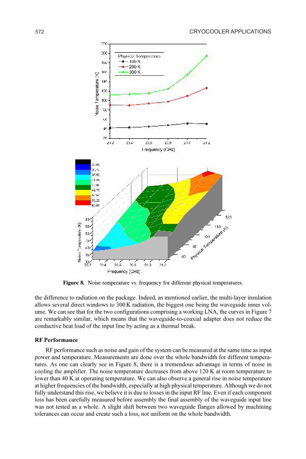
tures. As one can clearly see in Figure 8, there is a tremendous advantage in terms of noise in
cooling the amplifier. The noise temperature decreases from above 120 K at room temperature to
lower than 40 K at operating temperature. We can also observe a general rise in noise temperature
at higher frequencies of the bandwidth, especially at high physical temperature. Although we do not
fully understand this rise, we believe it is due to losses in the input RF line. Even if each component
loss has been carefully measured before assembly the final assembly of the waveguide input line
was not tested as a whole. A slight shift between two waveguide flanges allowed by machining
tolerances can occur and create such a loss, not uniform on the whole bandwidth.
Figure 8. Noise temperature vs. frequency for different physical temperatures.
572 CRYOCOOLER APPLICATIONS

P#
088
9
Figure 9. Gain of the system at room temperature and cryogenic operating temperature.
As we can see in Figure 9, the gain of the amplifier also benefits from the cool down and
increases from 21 dB at room temperature to 25 dB at 75K.
CONCLUSIONS AND FUTURE WORK
We successfully integrated different types of cryogenic LNAs onto a miniature rotary Stirling
cryocooler. The final system meets the initial objectives in terms of robustness, efficiency and RF
performance. The gain of the system is above 20 dB and its noise temperature is below 40K when
cryogenically cooled. Furthermore, the small size of the overall system allows integration directly
to the back of a satellite dish, which gives a key advantage in terms of final performance compare to
bigger systems that have to be mounted remotely from the antenna. The system will be further
tested after coupling to an antenna, and the improvement in G/T for the final receiver, compared to
the existing non-cooled LNA, will be evaluated.
Several upgraded configurations are envisaged: the insertion of an HTS filter is for instance
expected to improve further the signal quality; another major improvement will be to integrate
several channels on a single system. The latter, however, doubles or triples the heat load, depending
on how many channels are integrated. The need for a bigger cryocooler, say 2.5¶W at 77¶K arises
and so far we have not been able to identify any off-the-shelf cryocooler compact enough to meet
our needs.
ACKNOWLEDGMENT
Funded in part by U.S. Navy, SPAWAR PMW 170 through the Small Business Innovation
Research (SBIR) Phase 2.5 Program.
REFERENCES
1. R.R. Romanofsky, et al., “A Cryogenic K-Band Ground Terminal for NASA’S Direct-Data-Distribu-
tion Space Experiment,” IEEE Trans. Microwave Theory & Tech., vol. 48, no. 7, pp. 1216-1220, July
2000.
2. D. Gupta, T.V. Filippov, A.F. Kirichenko, D.E. Kirichenko, I.V. Vernik, A.Sahu, S.Sarwana,
P. Shevchenko, A. Talalaevskii, and O.A. Mukhanov, “Digital channelizing radio frequency receiver,”
IEEE Trans. Appl. Supercond., vol. 17, pp. 430-437, Jun. 2007.
3. I.V. Vernik, D. E. Kirichenko, V. V. Dotsenko, R. Miller, R. J. Webber, P. Shevchenko, A. Talalaevskii,
D. Gupta, and O.A. Mukhanov, “Cryocooled wideband digital channelizing RF receiver based on low-
pass ADC,” Supercond. Sci. Technol. vol. 20, pp. S323-S327, Nov. 2007.
573INTEGRATION OF CRYOGENIC LNA ON MINIATURE COOLER
P#
088
10 4. O.A. Mukhanov, D. Kirichenko, I.V. Vernik, T.V. Filippov, A. Kirichenko, R. Webber, V. Dotsenko,
A. Talalaevskii, J. C. Tang, A. Sahu, P. Shevchenko, R. Miller, S. B. Kaplan, S. Sarwana, and D.
Gupta, “Superconductor Digital-RF receiver systems,” IEICE Trans. Electron., vol. E91-C, No. 3, pp.
306-317, Mar. 2008.
5. D. Gupta, D.E. Kirichenko, V.V. Dotsenko, R. Miller, S. Sarwana, A. Talalaevskii, J. Delmas, R. J.
Webber, S. Govorkov, A. F. Kirichenko, I. V. Vernik, and J. Tang, “Modular, multi-function digital-
RF receiver systems,” IEEE Trans. Appl. Supercond. vol. 21, pp. 883-890, 2011.
6. G.A. Ediss, N. Horner, F. Johnson, D. Koller, A.R. Kerr, “WR-10 Waveguide Vacuum Feedthrough
for the ALMA Band-6 Cartridge,” ALMA Memo 536, National Radio Astonomy Observatory, 7 Sep-
tember 2005.
7. J.L. Hesler ., A.R. Kerr . and N. Horner, “A Broadband Waveguide Thermal Isolator,” ALMA Memo
469, 30 May 2003
8. H. Kubota and H. Takeuchi, “Low Thermal Leakage Coaxial Cable for HTS Devices,” IEEE Trans.
App. Supercond., Vol.9, No.2, June 1999.
9. Robert J. Webber, Charles J. Burroughs, and Masoud Radparvar, “Performance of a Cryocooled Nb
DC Programmable Voltage Standard at 4 K,” IEEE Trans. on Applied Superconductivity, vol. 17, no. 4,
pp. 3857-3861, December 2007
10. Y.H. Tang, R.T. Hunt, R. Robertazzi, M. Fisher, J. Coughlin, R. Patt, E.K. Track, and E. Potenziani,
“Cryocooled Primary Voltage Standard System,” IEEE Trans. On Instrumentation and Measurement,
Vol. 46, No. 2 (1997).
11. M. Barucci, E. Olivieri, E. Pasca, L. Risegari, G. Ventura, “Thermal conductivity of Torlon between
4.2 and 300¶K”, Cryogenics, Volume 45, Issue 4, April 2005, Pages 295-299.
12. Torlon® Resins Engineering Data, http://www.hycompinc.com/PDFs/Torlon%20Design
%20Manual.pdf
13. Ricor’s website, http://www.ricor.com/Index.asp?ArticleID=178&CategoryID=59&Page=1
574 CRYOCOOLER APPLICATIONS