compact lowpass ladder filters using tapped coils
TRANSCRIPT

7/27/2019 Compact Lowpass Ladder Filters Using Tapped Coils
http://slidepdf.com/reader/full/compact-lowpass-ladder-filters-using-tapped-coils 1/4
Compact lowpass ladder filters using tapped coilsNagendra Krishnapura, Varun Gupta, & Neetin Agrawal
Department of Electrical Engineering, Indian Institute of Technology, Madras, Chennai 600 036, India
Abstract— Compact passive LC ladder lowpass filters forpulse shaping are realized using a single inductor with multipletaps. Mutual coupling between different inductors in a ladderresults in zeros on the real and imaginary axis and can causean undershoot in the step response and reduced attenuation inthe stopband. Techniques to mitigate these effects are described.A seventh order Bessel filter is realized using the proposedtechnique in a 0.18 µm CMOS process. This filter exhibits anundershoot of 1.3% and provides a stopband attenuation of 37 dB. It occupies 0.048 mm2, which is at least 15% smallerthan a realization with separate spirals for each inductor.
I. MOTIVATION
50Ω 50Ω
+
Vo
-
+
Vs
-
1.1788nH 0.5382nH
0.9584pF 0.3412pF 0.0740pF
50Ω
+
Vs
-
+
Vo
-
50Ω
0.9617pF
1.1726nH
0.3688pF
0.3458nH
0.0469pF
0.7449nH
0.2228pF
(a)
(b)
L2 L4
C1 C3 C5
C5
L4
C3
L2
C1
L6
C7
Fig. 1. 7.5GHz bandwidth Bessel filters for pulse shaping 10Gb/s data
On chip LC lowpass ladder filters are used for real-
ization of pulse shaping filters in broadband communication
systems[1] and delay lines in equalizers[2]. Pulse shaping
filters are used in broadband communications systems for
limiting rise times of pulses and eliminating high frequency
noise. These filters usually have a 3 dB bandwidth that is
75% of the data rate[1], [3]. Fig. 1 shows fifth and seventh
order LC ladder Bessel filters for pulse shaping 10 Gb/s data.
Conventional implementations of these filters on an integrated
circuit, such as the one in [1] require a large area as the
inductors have to be laid out sufficiently far from each other
to avoid coupling.The inductors in a lowpass LC ladder filter form a
chain and can also be thought of as a single inductor with
multiple taps. Realizing separate coils for a number of induc-
tors occupies a larger area than realizing the total inductance
using a single coil. This is due to positive mutual coupling
between different parts of the coil. Since inductors are usually
the largest components on integrated circuits, significant chip
area can be saved by using a single inductor with multiple
taps instead of separate inductors which need to be laid out far
from each other. On the other hand, with a single tapped coil,
mutual coupling between different inductors causes deviations
in the pulse response and the frequency response which need
to be corrected.
In the next section, we compare a single inductor with
multiple taps to multiple spirals. In section III we analyze the
effect of coupling between different inductors in a ladder filter.
Section IV deals with techniques to restore the pulse response
of the filter to the ideal one in presence of mutual coupling.
Example realization of a Bessel filter using the proposed
techniques are shown in section V. Detailed simulation results
are shown in section VI.
I I . SINGLE INDUCTOR WITH MULTIPLE TAPS
3T110µm sq.1.173nH
3T85µm sq.0.74nH
3T60µm sq.0.35nH
4T135µm sq.2.2632nH
total area = 56375µm2 total area = 27225µm2
(a) (b)
1.1726nH 0.3458nH0.7449nH 2.2632nH
Fig. 2. Inductors in Fig. 1(b): (a) separate spirals, (b) single spiral (Squarespirals, 6 µm wide metal lines, 5 µm inter-turn spacing, 30 µm clearance
between and around inductors.)
Fig. 2(a) shows a simplified layout of the three in-
ductors used for the filter in Fig. 1(b). Fig. 2(b) shows the
total inductance (2.26 nH) realized using a single spiral with
the same metal width and spacing as in Fig. 2(a). The area
occupied by the single inductor is less than half the area
occupied by the three inductors1.
Realizing the total inductance as a single spiral results
in mutual coupling between different coils. For on chip spirals,
the coupling coefficient between turns is 0.6 or less.
I I I . EFFECT OF COUPLING BETWEEN INDUCTORS IN A
LADDER FILTER
When the total inductance in a ladder is laid out as a
single spiral, there will be mutual coupling between different
inductors. This coupling is highest for adjacent inductors and
reduces as one goes down the ladder. The coupling between
adjacent coils and alternate coils are analyzed below.
The transfer function of the fifth order filter (Fig. 3(a))
with a mutual inductance M 24 = k 24
√ L2 L4 between adjacent
1After this paper was accepted to ISCAS , the author became aware of [4]which describes the same idea. This work was done independently of [4] andreferences therein.
978-1-4244-3828-0/09/$25.00 ©2009 IEEE 53

7/27/2019 Compact Lowpass Ladder Filters Using Tapped Coils
http://slidepdf.com/reader/full/compact-lowpass-ladder-filters-using-tapped-coils 2/4
R
+
Vs
-
+
Vo
-
RL2 L4
C1 C3 C5
M24
R
+
Vs
-
+
Vo
-
RL2+M24 L4+M24
C1 C3 C5
-M24
(a)
(b)
Fig. 3. (a) Fifth order ladder filter with coupling between adjacent inductors,(b) Equivalent circuit with uncoupled inductors
inductors L2 and L4 is given by
V o(s)
V s(s) =
1− s2 M 24C 3
D5(s) (1)
where D5(s) is a fifth order polynomial in s. Because of mutual
coupling between adjacent coils, real zeros are introduced at
± 1/ M 24C 3. These zeros cause an undershoot in the pulse
response and a reduced attenuation in the stopband. This effect
can also be seen by using the well known representation of two
coupled coils in series using three uncoupled coils (Fig. 3(b)).
The series resonance of C 3 with the negative inductance − M 24
creates “notches”, i.e. zeros, on the real axis of the s plane. In
higher order filters, a pair of symmetric zeros are created on
the real axis for every pair of adjacent coupled inductors.
0 50 100 150 200−0.2
0
0.2
0.4
0.6
0.8
1
1.2
[ V o l t s ]
time / ps
Ideal Bessel
with k=0.310 20 30−0.1
0
0.180 100 120
0.85
0.9
0.95
1
1.05
Fig. 4. Step response with and without mutual coupling
To assess the effect of coupling between adjacentinductors, the filter in Fig. 3(a) is simulated with different
coupling coefficients between the inductors L2 and L4. In each
case, the effective inductance values L2+ M 24 and L4+ M 24 are
adjusted to the desired inductance values shown in Fig 1(a).
This is equivalent to simulating the ideal Bessel ladder filter
with uncoupled inductors and an extra negative inductance
− M 24 in series with C 3. Fig. 4 and Fig. 5 compare the step
response and the frequency response for k 24 = 0 and k 24 = 0.3.
The step response exhibits an undershoot and a slower rise
than the ideal response. Fig. 6 shows the undershoot in the
step response of 5thand 7thorder Bessel filters as a function of
10−1
100
101
102
−60
−50
−40
−30
−20
−10
0
d B
frequency / GHz
Fifth order Bessel filter magnitude response
Ideal Bessel
with k=0.3
Fig. 5. Magnitude response (normalized to dc gain)
0 0.1 0.2 0.3 0.4 0.5 0.60
0.5
1
1.5
2
2.5
3
coupling coefficient
o v e r s h o o t / u n d e r s h o o t [ % ]
Bessel filters with coupling between adjacent inductors
5th order
5th order
7th order7th order
overshoot
undershoot
Fig. 6. Undershoot due to mutual coupling
0 0.1 0.2 0.3 0.4 0.5 0.60
2
4
6
8
10
12
coupling coefficient
d B
Reduction in attenuation at 20GHz
5th order7th order
Fig. 7. Degradation of attenuation at 20 GHz due to mutual coupling
the coupling coefficient. Fig. 7(b) shows the degradation in the
attenuation of these filters at 20 GHz. This is representative of
the stopband attenuation.
In filters with three or more inductors, there will also
54
7/27/2019 Compact Lowpass Ladder Filters Using Tapped Coils
http://slidepdf.com/reader/full/compact-lowpass-ladder-filters-using-tapped-coils 3/4
be mutual coupling between inductors that are not adjacent to
each other. Consider the seventh order ladder filter in Fig. 1(b)
with a mutual inductance M 26 = k 26
√ L2 L6 between L2 and L6.
Its transfer function is given by
V o(s)
V s(s) =
1− s2(C 3 +C 5) M 26− s4C 3C 5 L4 M 26
D7(s) (2)
where D7(s) is a seventh order polynomial in s. Two pairs of
zeros are created, one on the real axis and one on the imaginary
axis. The imaginary axis zeros will be at a higher frequency
than the real axis zeros. The effect of real axis zeros is as
described earlier. The imaginary axis zeros create a notch in
the frequency response. Because of the zeros, the attenuation
in the stopband will be reduced. As alternate inductors couple
more weakly than adjacent inductors, the zeros due to the
former can be expected to be at higher frequencies than those
due to the latter.
IV. REDUCING THE EFFECT OF COUPLING
If the coupling is small, its effect can be ignored in
certain applications. For instance, assume that a fifth order
Bessel filter is used for pulse shaping. The step response of
an ideal fifth order Bessel filter has an overshoot of about
1.1% (Fig. 6, k = 0). An undershoot of the same magnitude
can therefore be reasonably be permitted without undermining
the pulse shaping function. This indicates that, if the coupling
coefficient is less than 0.2, the filter with coupled inductors
can be used without modifications for pulse shaping.
In many cases, the coupling between alternate induc-
tors ( L2 and L6) is small enough to be ignored but coupling
between adjacent inductors is not. A technique to eliminate the
effect of coupling between adjacent coils is described below.
R
+
Vs
-
+
Vo
-
RL2 L4
C1 C3 C5
M24
R
+Vs
-
+Vo
-
RL2+M24 L4+M24
C1 C3 C5
(a)
(b)
Lc3=M24
Fig. 8. Cancelling the effect of coupling between adjacent inductors
As shown in Fig. 3(b), two coupled inductors with
one common node can be represented using two uncoupled
inductors and a negative inductance connected to the common
node. To cancel the effect of coupling, a positive inductor can
be connected in series with the branch containing the series
inductor as shown in Fig. 8(a). When the positive inductance
exactly cancels the negative inductance, the circuit reduces to
the one shown in Fig. 8(b) and the zeros (Eq. 1) disappear.
Even if the cancellation is not exact, the zeros will be moved
to higher frequencies on the real axis (if the net inductance
is negative) or on the imaginary axis (if the net inductance is
positive) of the s plane. As a result, the degradation in high
frequency attenuation and the undershoot or other deviations
in the pulse response will be reduced.
In practice, when the mutual inductance to be cancelled
is small (a few tenths of a nanohenry), it is not necessary to
explicitly implement the positive inductance used for cancel-
lation. The capacitor C 3 in Fig. 8 is connected to the inductor
somewhere along the spiral. The starting and ending nodes
of the spiral will be close to each other near the periphery.
The inductance of the interconnect used to connect C 3 to a
tap along the spiral helps cancel the negative inductance. To
minimize coupling between the main spiral and the compen-
sating inductance Lc3, the interconnect can be routed along the
centerlines of the square spiral as much as possible.
V. SEVENTH ORDER B ESSEL FILTER REALIZATION
1 1 1 1 1 1 1 1 1 1 1
1 1 1 1 1 1 1 1
1 1 1 1 1 1 1 1 1 1 1 1 1 1 1
1 1 1 1 1 1 1 1 1 1 1 1 1 1 1 1 1 1 1 1 1 1
1 1 1 1 1 1 1 1 1 1 1 1 1 1 1 1 1 1 2 2 2 2 2 2 2 2 2
2 2 2 2 2 2 2 2 2 2 2 2 2 2 2 2 2
2 2 2 2 2 2 2 2 2 2 2 2 2 2 2 2 2
2 2 2 2 2 2 2 2 2 2 2 2 2 2 2 2 2
2 2 2 2 2 2 2 2 2 2 2 2 2 2 2 2 2
2 2 2 2 2 2 2 2 2 2 2 2 2 2 2 2 2
2 2 2 2 2 2 2 2
2 2 2 2 2 2 2 2 2 2
2 2 2 2 2 2 2 2 2 2
2 2 2 2 2 2 2 2 2 2
2 2 2 2 2 2 2 2 2 2
2 2 2 2 2 2 2 2 2 2 2 2 2 2 2 2 2 2 2 2 2 2 2 2 2 2 2 2 2 2 2 2 2 2 2 2 2 2 2 2 2 2 2 2 2 2 2 2 2 2 2 2 2 2 2 2 2 2 2 2 2 2 2 2 2 2 2 2 2 2 2 2 2
2 2 2 2 2 2 2 2
2 2 2 2 2 2 2 2 2 2 2 2 2 2
2 2 2 2 2 2 2 2 2 2 2 2 2 2
2 2 2 2 2 2 2 2 2 2 2 2 2 2
2 2 2 2 2 2 2 2 2 2 2 2 2 2 2 2 2 2 2 2 2 2 2 2 2 2 2 2 2 2 2 2
2 2 2 2 2 2 2 2 2 2 2 2 2 2 2 2 2
2 2 2 2 2 2 2 2 2 2 2 2 2 2 2 2 2
2 2 2 2 2 2 2 2 2 2 2 2 2 2 2 2 2
2 2 2 2 2 2 2 2 2 2 2 2 2 2 2 2 2
2 2 2 2 2 2 2 2 2 2 2 2 2 2 2 2 2 2 2 2 2 2 2 2 2 2
2 2 2 2 2 2 2 2
2 2 2 2 2 2
2 2 2 2 2 2 2 2 2 2
2 2 2 2
2 2 2 2 2 2 2 2 2 2 2 2 2 2 2 2 2 2 2 2 2 2 2 2 2
2 2 2 2 2 2 2 2 2 2 2 2 2 2 2
2 2 2 2 2 2 2 2 2 2 2 2
2 2 2 2 2 2 2 2 2 2 2 2
2 2 2 2 2 2 2 2 2 2 2 2 2 2 2 2 2 2 2 2 2
2 2 2 2 2 2 2 2 2 2 2 2 2 2
2 2 2 2 2 2 2 2 2 2 2 2 2 2
2 2 2 2 2 2 2 2 2 2 2 2 2 2
2 2 2 2 2 2 2 2 2 2 2 2 2 2
2 2 2 2 2 2 2 2 2 2 2 2 2 2 2 2 2 2 2 2 2 2 2 2 2 2 2 2 2 2 2 2 2 2 2 2 2 2 2 2 2 2
2 2 2 2 2 2 2 2 2 2 2 2 2 2 2 2 2 2 2 2 2 2 2 2 2 2 2 2 2 2 2 2 2 2 2
2 2 2 2 2 2 2 2 2 2 2 2 2 2 2 2 2 2 2 2 2 2 2 2 2 2 2 2 2 2 2 2 2 2 2
2 2 2 2 2 2 2 2 2 2 2 2 2 2 2 2 2 2 2 2 2 2 2 2 2 2 2 2 2 2 2 2 2 2 2 2 2
2 2 2 2 2 2 2 2 2 2 2 2 2 2 2 2 2 2 2 2 2 2 2 2 2 2 2 2 2 2 2 2 2 2 2 2 2
2 2 2 2 2 2 2 2 2 2 2 2 2 2 2 2 2 2 2 2 2 2 2 2 2 2 2 2 2 2 2 2 2 2 2 2 2
2 2 2 2 2 2 2 2 2 2 2 2 2 2 2 2 2 2 2 2 2 2 2 2 2 2 2 2 2 2 2 2 2 2 2 2 2
2 2 2 2 2 2 2 2 2 2 2 2 2 2 2 2 2 2 2 2 2 2 2 2 2 2 2 2 2 2 2 2 2 2 2 2 2
2 2 2 2 2 2 2 2 2 2 2 2 2 2 2 2 2 2 2 2 2 2 2 2 2 2 2 2 2 2 2 2 2 2 2 2 2
2 2 2 2 2 2 2 2 2 2 2 2 2 2 2 2 2 2 2 2 2 2 2 2 2 2 2 2 2 2 2 2 2 2 2 2 2
2 2 2 2 2 2 2 2 2 2 2 2 2 2 2 2 2 2 2 2 2 2 2 2 2 2 2 2 2 2 2 2 2 2 2 2 2
2 2 2 2 2 2 2 2 2 2 2 2 2 2 2 2 2 2 2 2 2 2 2 2 2 2 2 2 2 2 2 2 2 2 2 2 2
2 2 2 2 2 2 2 2 2 2 2 2 2 2 2 2 2 2 2 2 2 2 2 2 2 2 2 2 2 2 2 2 2 2 2 2 2
2 2 2 2 2 2 2 2 2 2 2 2 2 2 2 2 2 2 2 2 2 2 2 2 2 2 2 2 2 2 2 2 2 2 2 2 2
2 2 2 2 2 2 2 2 2 2 2 2 2 2 2 2 2 2 2 2 2 2 2 2 2 2 2 2 2 2 2 2 2 2 2 2 2
2 2 2 2 2 2 2 2 2 2 2 2 2 2 2 2 2 2 2 2 2 2 2 2 2 2 2 2 2 2 2 2 2 2 2 2 2
2 2 2 2 2 2 2 2 2 2 2 2 2 2 2 2 2 2 2 2 2 2 2 2 2 2 2 2 2 2 2 2 2 2 2 2 2
2 2 2 2 2 2 2 2 2 2 2 2 2 2 2 2 2 2 2 2 2 2 2 2 2 2 2 2 2 2 2 2 2 2 2 2 2
2 2 2 2 2 2 2 2 2 2 2 2 2 2 2 2 2 2 2 2 2 2 2 2 2 2 2 2 2 2 2 2 2 2 2 2 2
2 2 2 2 2 2 2 2 2 2 2 2 2 2 2 2 2 2 2 2 2 2 2 2 2 2 2 2 2 2 2 2 2 2 2 2 2
2 2 2 2 2 2 2 2 2 2 2 2 2 2 2 2 2 2 2 2 2 2 2 2 2 2 2 2 2 2 2 2 2 2 2 2 2
2 2 2 2 2 2 2 2 2 2 2 2 2 2 2 2 2 2 2 2 2 2 2 2 2 2 2 2 2 2 2 2 2 2 2 2 2
2 2 2 2 2 2 2 2 2 2 2 2 2 2 2 2 2 2 2 2 2 2 2 2 2 2 2 2 2 2 2 2 2 2 2 2 2
2 2 2 2 2 2 2 2 2 2 2 2 2 2 2 2 2 2 2 2 2 2 2 2 2 2 2 2 2 2 2 2 2 2 2 2 2
2 2 2 2 2 2 2 2 2 2 2 2 2 2 2 2 2 2 2 2 2 2 2 2 2 2 2 2 2 2 2 2 2 2 2 2 2
2 2 2 2 2 2 2 2 2 2 2 2 2 2 2 2 2 2 2 2 2 2 2 2 2 2 2 2 2 2 2 2 2 2 2 2 2
2 2 2 2 2 2 2 2 2 2 2 2 2 2 2 2 2 2 2 2 2 2 2 2 2 2 2 2 2 2 2 2 2 2 2 2 2
2 2 2 2 2 2 2 2 2 2 2 2 2 2 2 2 2 2 2 2 2 2 2 2 2 2 2 2 2 2 2 2 2 2 2 2 2
2 2 2 2 2 2 2 2 2 2 2 2 2 2 2 2 2 2 2 2 2 2 2 2 2 2 2 2 2 2 2 2 2 2 2 2 2
2 2 2 2 2 2 2 2 2 2 2 2 2 2 2 2 2 2 2 2 2 2 2 2 2 2 2 2 2 2 2 2 2 2 2 2 2
2 2 2 2 2 2 2 2 2 2 2 2 2 2 2 2 2 2 2 2 2 2 2 2 2 2 2 2 2 2 2 2 2 2 2 2 2
2 2 2 2 2 2 2 2 2 2 2 2 2 2 2 2 2 2 2 2 2 2 2 2 2 2 2 2 2 2 2 2 2 2 2 2 2
2 2 2 2 2 2 2 2 2 2 2 2 2 2 2 2 2 2 2 2 2 2 2 2 2 2 2 2 2 2 2 2 2 2 2 2 2
2 2 2 2 2 2 2 2 2 2 2 2 2 2 2 2 2 2 2 2 2 2 2 2 2 2 2 2 2 2 2 2 2 2 2 2 2
2 2 2 2 2 2 2 2 2 2 2 2 2 2 2 2 2 2 2 2 2 2 2 2 2 2 2 2 2 2 2 2 2 2 2 2 2
2 2 2 2 2 2 2 2 2 2 2 2 2 2 2 2 2 2 2 2 2 2 2 2 2 2 2 2 2 2 2 2 2 2 2 2 2
2 2 2 2 2 2 2 2 2 2 2 2 2 2 2 2 2 2 2 2 2 2 2 2 2 2 2 2 2 2 2 2 2 2 2 2 2
2 2 2 2 2 2 2 2 2 2 2 2 2 2 2 2 2 2 2 2 2 2 2 2 2 2 2 2 2 2 2 2 2 2 2 2 2
2 2 2 2 2 2 2 2 2 2 2 2 2 2 2 2 2 2 2 2 2 2 2 2 2 2 2 2 2 2 2 2 2 2 2 2 2
2 2 2 2 2 2 2 2 2 2 2 2 2 2 2 2 2 2 2 2 2 2 2 2 2 2 2 2 2 2 2 2 2 2 2 2 2
2 2 2 2 2 2 2 2 2 2 2 2 2 2 2 2 2 2 2 2 2 2 2 2 2 2 2 2 2 2 2 2 2 2 2 2 2
2 2 2 2 2 2 2 2 2 2 2 2 2 2 2 2 2 2 2 2 2 2 2 2 2 2 2 2 2 2 2 2 2 2 2 2 2
2 2 2 2 2 2 2 2 2 2 2 2 2 2 2 2 2 2 2 2 2 2 2 2 2 2 2 2 2 2 2 2 2 2 2 2 2 2 2 2 2 2 2 2 2
2 2 2 2 2 2 2 2 2 2 2 2 2 2
2 2 2 2 2 2 2
2 2 2 2 2 2 2 2 2 2 2 2 2 2 2 2 2 2 2 2 2 2 2 2 2 2 2 2 2 2 2 2 2 2
2 2 2 2 2 2 2 2 2 2 2 2 2 2 2 2 2
2 2 2 2 2 2 2 2 2 2 2 2 2 2 2 2 2
2 2 2 2 2 2 2 2 2 2 2 2 2 2 2 2 2
2 2 2 2 2 2 2 2 2 2 2 2 2 2 2 2 2
2 2 2 2 2 2 2 2 2 2 2 2 2 2 2 2 2
2 2 2 2 2 2 2 2 2 2 2 2 2 2 2 2 2 2 2 2 2 2 2 2 2 2 2 2 2
2 2 2 2 2 2 2 2
2 2 2 2 2 2 2 2 2
2 2 2 2 2 2 2 2 2 2 2 2 2 2 2
2 2 2 2
2 2 2 2 2 2 2 2 2 2 2 2 2 3 3 3 3 3 3 3 3 3 3 3 3 3 3
3 3 3 3 3 3 3 3 3 3 3 3 3 3
3 3 3 3 3 3 3 3 3 3 3 3 3 3 3 3 3 3 3 3 3 3
3 3 3 3 3 3 3 3 3 3 3 3 3 3 3 3 3
3 3 3 3 3 3 3 3 3 3 3 3 3 3 3 3 3
3 3 3 3 3 3 3 3 3 3 3 3 3 3 3 3 3
3 3 3 3 3 3 3 3 3 3 3 3 3 3 3 3 3 4 4 4 4 4 4 4
4 4 4 4 4 4 4 4 4
5 5 5 5 5 5 5 5 5 5 5 5 5 5 5 5 5 5 5 5 5 5 5 5 6 6 6 6 6 6 6 6 6 6 6 6 6 6
6 6 6 6 6 6 6 6 6 6 6 6 6 6
6 6 6 6 6 6 6 6 6 6 6 6 6 6
6 6 6 6 6 6 6 6 6 6 6 6 6 6 6 6 6 6 6 6 6 6 6 6 6 6 6 6 6 6 6 6
6 6 6 6 6 6 6 6 6 6 6 6 6 6 6 6 6
6 6 6 6 6 6 6 6 6 6 6 6 6 6 6 6 6
6 6 6 6 6 6 6 6 6 6 6 6 6 6 6 6 6
6 6 6 6 6 6 6 6 6 6 6 6 6 6 6 6 6
6 6 6 6 6 6 6 6 6 6 6 6 6 6 6 6 6 2 2 2 2 2 2 2 2 2 2 2 2 2 2 2 2 2 2 2 2 2 2 2 2 2 2 2 2 2 2 2 2 2 2 2 2 2 2 2 2 2 2 2 2
2 2 2 2 2 2 2 2 2 2 2 2 2 2 2 2 2 2 2 2 2 2
2 2 2 2 2 2 2 2 2 2 2 2 2 2
2 2 2 2 2 2 2 2 2 2 2 2 2 2
2 2 2 2 2 2 2 2 2 2 2 2 2 2
2 2 2 2 2 2 2 2 2 2 2 2 2 2 2 2 2 2 2 2 2 2 2 2 2 2 2 2 2 2 2 2
2 2 2 2 2 2 2 2 2 2 2 2 2 2 2 2 2
2 2 2 2 2 2 2 2 2 2 2 2 2 2 2 2 2
2 2 2 2 2 2 2 2 2 2 2 2 2 2 2 2 2
2 2 2 2 2 2 2 2 2 2 2 2 2 2 2 2 2
2 2 2 2 2 2 2 2 2 2 2 2 2 2 2 2 2
200um
e x t r a 5 u m
g a p
C 1
C 5
1 5 0 u m
C 3
C 7
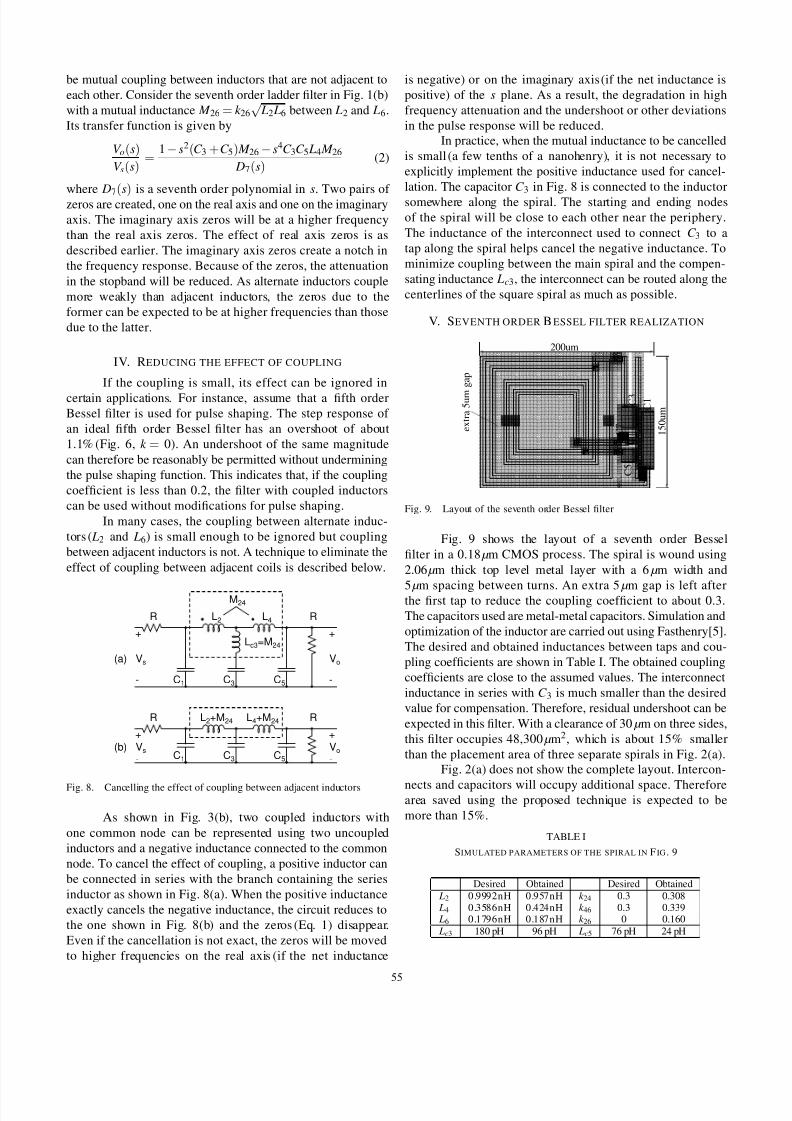
Fig. 9. Layout of the seventh order Bessel filter
Fig. 9 shows the layout of a seventh order Bessel
filter in a 0.18 µm CMOS process. The spiral is wound using
2.06 µm thick top level metal layer with a 6 µm width and
5 µm spacing between turns. An extra 5 µm gap is left afterthe first tap to reduce the coupling coefficient to about 0.3.
The capacitors used are metal-metal capacitors. Simulation and
optimization of the inductor are carried out using Fasthenry[5].
The desired and obtained inductances between taps and cou-
pling coefficients are shown in Table I. The obtained coupling
coefficients are close to the assumed values. The interconnect
inductance in series with C 3 is much smaller than the desired
value for compensation. Therefore, residual undershoot can be
expected in this filter. With a clearance of 30 µm on three sides,
this filter occupies 48,300 µm2, which is about 15% smaller
than the placement area of three separate spirals in Fig. 2(a).
Fig. 2(a) does not show the complete layout. Intercon-
nects and capacitors will occupy additional space. Thereforearea saved using the proposed technique is expected to be
more than 15%.
TABLE I
SIMULATED PARAMETERS OF THE SPIRAL IN F IG . 9
Desired Obtained Desired Obtained
L2 0.9992nH 0.957nH k 24 0.3 0.308 L4 0.3586nH 0.424nH k 46 0.3 0.339 L6 0.1796nH 0.187nH k 26 0 0.160
Lc3 180 pH 96 pH Lc5 76 pH 24 pH
55

7/27/2019 Compact Lowpass Ladder Filters Using Tapped Coils
http://slidepdf.com/reader/full/compact-lowpass-ladder-filters-using-tapped-coils 4/4
VI . SIMULATED RESULTS
0 50 100 150 200−0.2
0
0.2
0.4
0.6
0.8
1
time / ps
V o l t s
Ideal Bessel
Extracted layout
10 20 30−0.02
0
0.0280 100 120
0.85
0.90.95
1
1.05
Fig. 10. Step response of ideal and realized seventh order Bessel filters
100
101
102
−60
−50
−40
−30
−20
−10
0
frequency / GHz
d B
Ideal Bessel
Extracted layout
Fig. 11. Magnitude response of ideal and realized seventh order Bessel filters
0 50 100 150 200
−1
−0.5
0
0.5
1
Ideal seventh order Bessel filter
0 50 100 150 200
−1
−0.5
0
0.5
1
time / ps
Extracted layout
Fig. 12. Output eye diagrams with 10Gb/s data
The filter in Fig. 9 is simulated including all the
inductances, parasitic capacitances, and series resistances. The
inductance of the spiral, the tap connections, and the ground
line and the coupling coefficients between them are simulated
using Fasthenry. The parasitic capacitances and resistances are
extracted from the layout. The resulting circuit is simulated
in the time and frequency domains. The realized filter has
an additional loss due to series resistance of the spiral. For
clarity, the pulse and frequency responses are normalized to
the dc gain of the filter.
Fig. 10 shows the step response of the filter. It shows
an undershoot of 1.3% and an overshoot of 0.3%. The residual
undershoot and the slowing down in the step response is
due to the still uncompensated zero caused mainly by mutual
inductance between L2 and L4. Fig. 11 shows the frequency
response of the filter. The magnitude error is very small in
the passband. The filter provides a high frequency attenuation
better than 37 dB. There is a notch in the magnitude response.
This is due to parasitic capacitances between the turns of the
inductor which create parallel LC branches in the ladder.
Fig. 12 shows the eye diagrams at the output of the
ideal and the realized filters. The output eye from the realized
filter has a slightly greater closure and asymmetry.
VI I . CONCLUSIONS
A single spiral with multiple taps can be used to realize
lowpass LC ladder filters with a reduced area. Use of a single
spiral results in mutual coupling between inductors of the
ladder. Coupling between adjacent inductors creates a pair
of symmetric zeros on the real axis and coupling between
alternate inductors creates two pairs of symmetric zeros on the
real and imaginary axes. The real axis zeros due to coupling
between adjacent coils can be eliminated using inductors
in series with the capacitors. In practice, the interconnect
inductance from the taps along the spiral to the capacitors
can be used to to eliminate the zeros or to move them tohigher frequencies, thus realizing a better approximation to
the desired transfer function.
The proposed techniques also benefit conventional lad-
der filter realizations with uncoupled inductors. The inductors
can be moved closer to each other and the effect of resultant
coupling can be eliminated using inductors in series with the
capacitors. These techniques are also applicable to filters using
spirals on a printed circuit board.
Since inductors occupy a large area and require large
gaps to reduce mutual coupling to negligible levels, using a
single spiral or moving the spirals closer result in significant
area savings.
REFERENCES
[1] A. Boulouard et al., “Wide-band GaAs MMIC low-pass filters,” Gallium Arsenide Applications Symposium, GAAS 1994, 28-30 April 1994, Italy.
[2] Hui Wu et al., “Integrated transversal equalizers in high-speed fiber-opticsystems,” IEEE Journal of Solid State Circuits, pp. 2131-2137, vol. 38,issue 12, Dec. 2003.
[3] “Standard and Customs Bessel Filters” from Nanowave technologies,http://www.nanowavetech.com/prod_rf_components.htm
[4] T. Ito, K. Okada, K. Masu, “Characterization of On-Chip Multi-PortInductors for Small-Area RF Circuits”, IEEE Transactions on Circuitsand Systems I: Regular Papers, Accepted for future publication.
[5] “Fasthe nry: A multipole a ccelerated field solver”,http://www.rle.mit.edu/cpg/research_codes.htm
56