comparative analysis and simulation of selected · pdf fileenvironmental pollution control of...
TRANSCRIPT

Comparative analysis and simulation of selected components of modern
power systems (EPS, PES)
of ‘classical’ aircraft and ‘More/ All Electric Aircraft’ (MEA/ AEA)
LUCJAN SETLAK, RAFAŁ KOWALIK
Department of Avionics and Control Systems
Polish Air Force Academy
ul. Dywizjonu 303 nr 35, 08-521 Deblin
POLAND
[email protected], [email protected], http://www.wsosp.pl/index.php/pl/
Abstract— The work deals with the issues of modern architecture of power in the field of electrical power
systems EPS (Electric Power Systems) and power electronic power systems PES (Power Electronics Systems),
both civil 'classical' aircraft airline concerns Airbus and Boeing (A-320, B-767) and military Lockheed Martin (F-16), as well as civil aircraft more/ fully electric MEA/ AEA (A-380 and A-350XWB, B-787) and military
JSF (Joint Strike Fighter) F-35 and F-22 Raptor. Based on the above, the authors conducted a comparative
analysis of these systems, with particular emphasis on making the simulation of selected components of individual systems (EPS, PES) including their mathematical models in a dynamic perspective. The main
objective of this work was to simulate a range of EPS (synchronous motor) and on the PES converter (48-
pulse), presenting their mathematical models and based on them making a comparative analysis of advanced
power systems with the trend of MEA/ AEA plane. In the final part, the paper presents the main conclusions arising from the analysis and simulation of selected components of the architecture of power systems (EPS,
PES) of 'classical' aircraft and the advanced in line with the new trend of 'MEA/ AEA.
Key-Words: - More/ All Electric Aircraft (MEA/ AEA), Electric Power Systems (EPS), Power Electronics
Systems (PES)
1 Introduction Today, both in the case of civil aviation (Airbus, Boeing), the 'classic' aircraft (A-320, B-767), with
particular emphasis on aircraft in line with the new
trend in the field of power 'MEA/ AEA' (A-380 and A-350XWB, B-787), as well as in the context of a
military aircraft (Lockheed Martin), and in
'conventional' aircraft (F-16) and compatible with
the modern trend of MEA/ AEA (JSF F-35, F-22 Raptor), you can see the dynamic development of
modern architecture of electrical power systems
EPS including high voltage power systems HVDC (High Voltage Direct Current) voltage range ±270V
DC (540V DC) for main power of a plane and 350V
DC for the power drive unit MEE (More Electric Engine) and power electronic power systems PES
[1]. In the context of a brief introduction to this
subject it should be noted that the advanced power
systems (EPS, PES) used on modern aircraft (airplanes, helicopters), primarily on technologically
advanced aircraft, ie. in line with the concept of
MEA/ AEA, they belong to a group so called on-board autonomous power systems ASE
(Autonomous Electric Power Systems), referred to,
among others, as integrated power systems IPS
(Integrated Power Systems) [2]. Based on the above, a comparative analysis of selected components of
modern power systems (EPS, PES) in the context of
the aircraft 'classic' and 'More Electric Aircraft' were carried out according to specific criteria, namely:
types of electricity generation systems, their
evolution and key sources in terms of power produced by these advanced systems used in today's
military and civil aircraft (Fig. 1). Now, in modern
aircraft (civil, military) there is an electric power
system of power supply DC/ AC, whereby it should be noted that in the most advanced aircraft, both
civilian as well as military, there is a tendency in the
direction of the architecture of the power supply system of alternating current voltage as leading,
using sources of electricity generation in the form of
integrally connected team starter/ generator AC variable frequency AS/ G VF (Alternating Starter/
Generator Variable Frequency), whose main
purpose is to provide electricity to the subsystem,
based on the supply and distribution of electricity PMAD (Power Management and Distribution)
resistant to damage [3], [4]. Another trend
distinguishing 'classic' aircraft of aircraft consistent with the concept MEA/ AEA, is to replace the
WSEAS TRANSACTIONS on POWER SYSTEMS Lucjan Setlak, Rafał Kowalik
E-ISSN: 2224-350X 338 Volume 11, 2016

power supply on-board electrical network,
previously used on 'conventional' aircraft in the
form of mechanical, pneumatic and hydraulic
energy, by one kind of energy – electricity, which a domain of modern aircraft compatible with the
modern concept of power (MEA/ AEA). Therefore,
in accordance with input trend of more electric plane, there are expressions such as: optimization of
plane energy POA (Power Optimized Aircraft), and
with it a more open technology in the field of electricity MOET (More Open Electrical
Technology), developed by the Air Airbus company
and also innovative solutions were developed in the
field of power electronics systems, ie. advanced technology PES (Power Electronics Systems) [5]. In
the context of power electronic power systems
(PES) their main components play a key role, which are multi-pulse converters (6-, 12- and 18-, 24-
pulse), and even 48-pulse, which will be the subject
of detailed analysis later in this article.
2 The Architecture of Modern Power
Systems (EPS, PES)
2.1 'Classical' civil aircraft (A-320, B-767) in
line with the trend 'MEA/ AEA' (A-380
and A-350XWB, B-787) The development of advanced systems (EPS, PES)
of modern aircraft, types of sources (generators) for
the generation of electricity and the level generated by their power, in the context considered in this
paper airplanes (civil, military) 'classic' and 'More/
All Electric Aircraft' are listed below (Figure 1).
Fig. 1 Evolution of EPS aircraft ‘classic’ and ‘MEA/
AEA’ [6], [7]
Now, in modern aviation, both civil aircraft 'classic'
(A-320, B-767) and 'More/ All Electric Aircraft' (A-
380 and A-350XWB, B-787) and in the case of
military aircraft 'classic' (F-16) and 'More/ All
Electric Aircraft' (JSF F-35, F-22 Raptor), there are
the following systems for the generation of
electricity on board of the plane, illustrated in the following figure (Figure 2).
Fig. 2 Types of systems generating electricity on
board aircraft 'classic' and 'MEA/ AEA' [6], [7]
2.2 Military aircraft 'classic' (F-16) and in
line with the trend of 'MEA/ AEA' (JSF
F-35, F-22 Raptor) Changes in the dynamic development in the field of
electrical machines and its related fields of
electronics and power electronics are closely linked
to the implementation of the concept of more electric plane MEA (More Electric Aircraft),
applied not only to civil aircraft (Airbus, Boeing),
but also for military aircraft (Lockheed Martin), which was established under the project MOET or
in the near future, the concept of fully electric
aircraft AEA (All Electric Aircraft). According to the above concept of the basic subsystems of the
JSF F-35, such as a subsystem of hydraulic
cylinders of flight control EHA (Electohydrostatic
Actuators) subsystem of gear motor driving the fuel pump and the air-driven subsystem of
environmental pollution control of aircraft ECS
(Environmental Control System) are powered electrically by an electric drive motor. The major
component of EPS system, which is a set of starter/
generator AS/ G is designed to supply electric power subsystem PMAD shatterproof. In addition, it
should be noted that in the modern aviation
advanced technology plays increasingly frequent
role in the field of high-voltage HVDC (± 270V DC, 350V DC) [6].
WSEAS TRANSACTIONS on POWER SYSTEMS Lucjan Setlak, Rafał Kowalik
E-ISSN: 2224-350X 339 Volume 11, 2016

Fig. 3 Simplified diagram of EPS system military
aircraft F-22 Raptor [8]
For example, in military aircraft F-22 Raptor
voltage of 270V DC is used to power not only specific components of the EPS, as is in the case of
advanced civil aircraft (A-380 and A-350XWB, B-
787), but also acts as the main power system of
aircraft, which has been illustrated in the figure above (Fig. 3).
3 Comparative Analysis and Dynamic
Mathematical Model of the Selected
Components of Modern Power
Systems (EPS, PES)
3.1 Synchronous motor teams AS/ G VF
(Alternating Starter/ Generator Variable
Frequency) EPS system in accordance
with the trend of MEA/ AEA Currently, the main source of electricity generation
used in most of the aircraft both civilian and
military (large and small) is a synchronous motor (starter) three-phase alternating current team AS/ G
VF. It should be noted that in modern aerospace
majority of electric drives, are synchronous motors
of permanent magnet PMSM (Permanent Magnet Synchronous Motor). In addition, the above type of
engine works most efficiently in a situation where
high dynamics of the object in which it was placed is required, small pulsations of electrodynamic
momentum and a large speed range. Mathematical
record of phenomena occurring in a synchronous motor with permanent magnets is as follows. In
considering dynamics of the supply system
(frequency inverter voltage) was omitted. This is
due to the high switching frequency of power
transistors, which is typically 10-20 [kHz].
Therefore the frequency converter has a much
shorter time constants than analyzed synchronous motor. The dynamic mathematical model of
induction motor cage, stored in the rotating speed of
ωK coordinate system according to [9], [10], [11],
[15], [16] and [21] can be represented in the
following form:
(1)
(2)
(3)
(4)
The method of vector control induction motor SVM-DTC (Direct Torque Control - Space Vector
Modulation) (1) uses a mathematical model of the
motor rotating synchronously with the stator flux vector coordinates. This means writing equations of
engine using the spatial vector method [9], [10],
[11], [15], [16] and [21], wherein an actual axis coordinate system is the stator flux:
(5)
This approach leads to the following equations [2],
[10]:
(6)
(7)
(8)
(9)
(10)
(11)
(12)
(13)
(14)
(15)
WSEAS TRANSACTIONS on POWER SYSTEMS Lucjan Setlak, Rafał Kowalik
E-ISSN: 2224-350X 340 Volume 11, 2016

In the above equations in the following markings are
used: isd, isq – longitudinal and transverse component
of the stator current vector, stored in a moving
coordinate system associated with , LR – inductance of the rotor, LS – stator inductance, L –
mutual inductance, RR – rotor resistance, RS – stator
resistance, pb – the number of pole pairs of the
motor, – the angular velocity of rotor, –
pulsation (speed) stream . The following figure
(Figure 4) shows a simplified block diagram of the
power supply system of the F-16 aircraft.
Fig. 4 Simplified power system of F-16 electrical installation
3.2 48-Pulse Transmitter of Power
Electronic Power System PES in
Accordance with the Trend of MEA/
AEA For the currently used power electronics supply
systems PES elements responsible for the conversion of the AC to DC power, multi-pulse
transmitters are in most cases used in 12-pulse or
24-pulse rectifiers. However, in the literature [14], [22] developed models of 48-pulse rectifiers can be
found. One such characteristic of the sensor is the
ability to produce significantly less harmonic distortion of the output voltages, and less likelihood
of loss of power in the system, as was in the case of
6-, 12- and 18- and 24-pulse rectifiers. The results
presented in the literature [13], [22] from the contained simulation it can be seen that instability of
48-pulse rectifier is possible resulting from
overloading the system and the possibility of changes in the voltage harmonics. Emerging
incompatibilities indirectly can be eliminated by
using suitably phased voltage three-phase system of
7.5°, this value will provide valuable full operation of 48-pulse rectifier. Also, be sure to make
symmetrical movements of all three voltages
produced by the transformer windings. Transmitter model shown in Figures 5-6 consists of four
identical 12-pulse rectifiers, associated with four 12-
pulse transformer windings with offset. Generally
speaking, the 48-pulse converter phase shifts are
implemented in the following way, two voltage transformers are offset by the value of 3.75° is
connected directly to the 24-pulse rectifiers. Same
situation is in the next two transformers. The basic element of the power supply is AC transformer. The
transformer at 400 Hz (the frequency used in
aviation) under load drops occur in the output voltage caused by the resistance of the primary
winding and a secondary resistance of the core
losses and leakage inductance of the primary
winding and secondary (particularly for high power transformers). Transformer manufacturers usually
provide only the basic parameters of the
transformer: the power output on the secondary winding, rated primary voltage, secondary voltage at
the maximum load resistance, the secondary
winding current at maximum load.
Fig. 5 Block diagram of the 48-pulse rectifier in supply system of F-16 electrical installation (part
with the generator harmonic signal with a phase of
0° and 30°)
In the presented system, you can see the connectors
and transformer circuits 24- pulse rectifiers in the final result from the 48-pulse rectifier. Modeled
system can be used in devices or systems supplying
high voltage applications with high power without
the use of filtering systems due to the treatment of its very low harmonic distortion arising from the
side that produces alternating current. It should be
noted that the output voltages from the system are characterized by standard values of the harmonics
L1 (0 )o
L3 (30 )o
L2 ( )30o
L4 ( )30o
H2 ( -7.5 )30o o
H2 ( -7.5 )30o o
-
+
WSEAS TRANSACTIONS on POWER SYSTEMS Lucjan Setlak, Rafał Kowalik
E-ISSN: 2224-350X 341 Volume 11, 2016
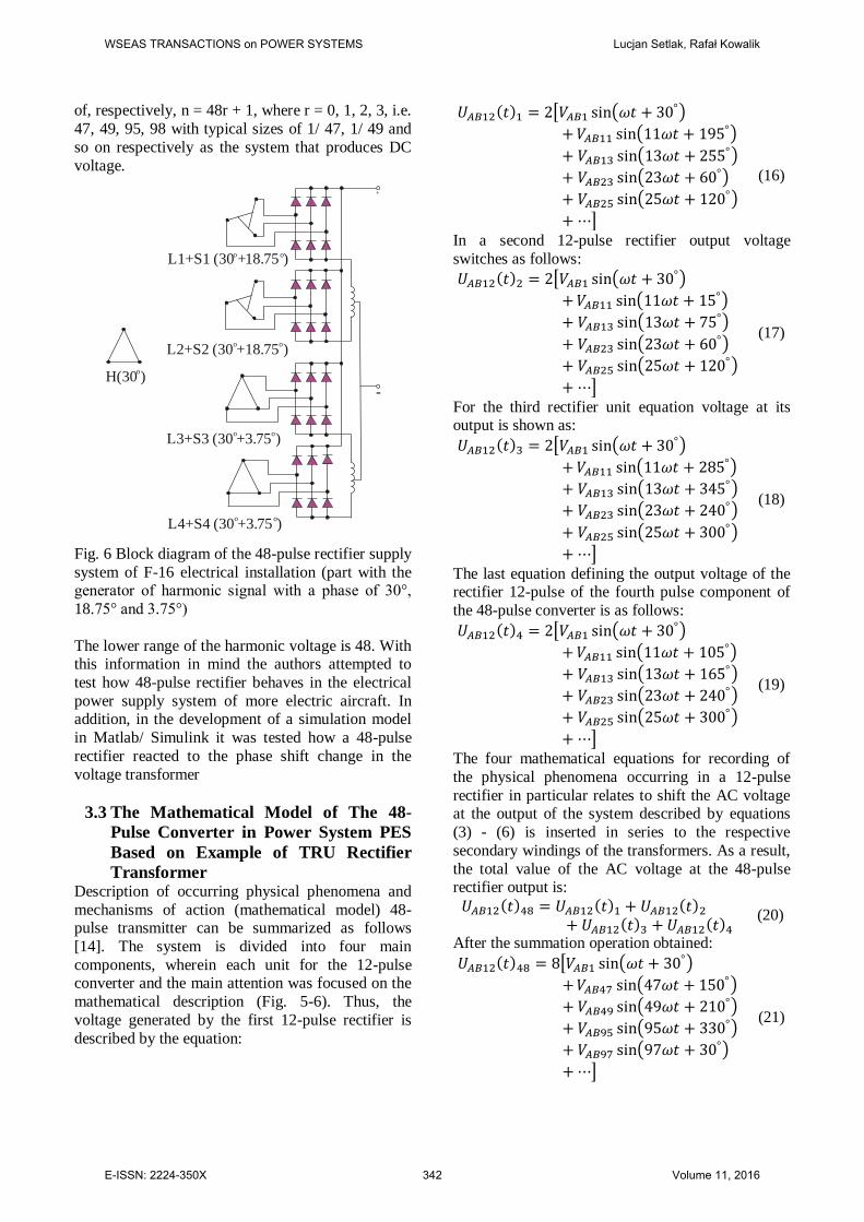
of, respectively, n = 48r + 1, where r = 0, 1, 2, 3, i.e.
47, 49, 95, 98 with typical sizes of 1/ 47, 1/ 49 and
so on respectively as the system that produces DC
voltage.
Fig. 6 Block diagram of the 48-pulse rectifier supply
system of F-16 electrical installation (part with the generator of harmonic signal with a phase of 30°,
18.75° and 3.75°)
The lower range of the harmonic voltage is 48. With this information in mind the authors attempted to
test how 48-pulse rectifier behaves in the electrical
power supply system of more electric aircraft. In addition, in the development of a simulation model
in Matlab/ Simulink it was tested how a 48-pulse
rectifier reacted to the phase shift change in the
voltage transformer
3.3 The Mathematical Model of The 48-
Pulse Converter in Power System PES
Based on Example of TRU Rectifier
Transformer Description of occurring physical phenomena and
mechanisms of action (mathematical model) 48-pulse transmitter can be summarized as follows
[14]. The system is divided into four main
components, wherein each unit for the 12-pulse converter and the main attention was focused on the
mathematical description (Fig. 5-6). Thus, the
voltage generated by the first 12-pulse rectifier is
described by the equation:
(16)
In a second 12-pulse rectifier output voltage
switches as follows:
(17)
For the third rectifier unit equation voltage at its output is shown as:
(18)
The last equation defining the output voltage of the rectifier 12-pulse of the fourth pulse component of
the 48-pulse converter is as follows:
(19)
The four mathematical equations for recording of
the physical phenomena occurring in a 12-pulse
rectifier in particular relates to shift the AC voltage at the output of the system described by equations
(3) - (6) is inserted in series to the respective
secondary windings of the transformers. As a result,
the total value of the AC voltage at the 48-pulse rectifier output is:
(20)
After the summation operation obtained:
(21)
L1+S1 (30 + )o o18.75
-
+
H( )30o
L2+S2 (30 + )o o
18.75
L3+S3 (30 + )o o
3.75
L4+S4 (30 + )o o
3.75
WSEAS TRANSACTIONS on POWER SYSTEMS Lucjan Setlak, Rafał Kowalik
E-ISSN: 2224-350X 342 Volume 11, 2016

Thus, ultimately the output voltage generated by the
neutral 48-pulse rectifier can be written as:
(22)
where: n = (48r ± 1), r = 0, 1, 2, … . A voltage
and having a sine wave-like
shape, are offset with an angle of 120° and 240°
degrees relative to the voltage .
4 Examples of Simulations of Selected
Components (EPS, PES), used for
Advanced Aircraft in line with the
Concept of More Electric Aircraft
MEA/ AEA
The main objective of carrying out computer
simulations of selected components, which included
a synchronous motor and 48-pulse converter, was to
assess the performance of modern power systems (EPS, PES), used in advanced aircraft in use today,
both civilian and military. Therefore, the authors
have made an exemplary analysis of the operation of the electric drive in modern power systems (EPS,
PES) aircraft in accordance with the trend of More
Electric Aircraft and their comparison. Given the
complexity of both these power systems, particular attention is focused on two components that play an
important role in modern electrical systems of the
aircraft. These are three-phase synchronous motor PMSM and the elements responsible for the
processing of AC to DC current (multi-pulse
converters). Computer simulations were carried out in the computer program Matlab/ Simulink. At the
beginning fixed parameters are defined that will be
used in computer simulations performed. Thus, one
used relative units related to the rating of the three-phase synchronous motor with permanent magnets
Rs = 0,2 [Ω], Ld = Lq = Ls = 0,0085 [H], Ψf = 0.175
[Vs], p = 4. The following illustrations show the models of
power 3-phase synchronous motor AC (Fig. 6) and
the transformer rectifier (Fig. 7) TRU (Transformer Rectifier Unit), made in Matlab/ Simulink.
Fig. 7 PMSM motor model in Matlab/ Simulink
In the pad motor the following values of parameters
were defined characterizing his work: Power output (Power Generation) 100 [kVA], operating frequency
f = 400 [Hz], line-to-line voltage of 200 [V].
Fig. 8 TRU model component in Matlab/ Simulink
Received at this stage of simulation research results
in a waveform of voltages and currents are shown in a number of the following illustrations (Fig. 9-16).
On the other hand, comparative analysis of modern
power systems (EPS, PES), in accordance with the trend of MEA/ AEA has been made on two stages of
the electrical system of the aircraft. The first relates
to the parameters of the output of synchronous AC
motor, while the second concerns the size of the generated output transducers AC/ DC.
Fig. 9 Course of output current in a ABC three-
phase synchronous motor PMSM
WSEAS TRANSACTIONS on POWER SYSTEMS Lucjan Setlak, Rafał Kowalik
E-ISSN: 2224-350X 343 Volume 11, 2016

Fig. 10 The course of the output voltage in a ABC
three-phase synchronous motor PMSM
Fig. 11 Decrease in the voltage cross the Transformer and Transformer Rectifier Unit (TRU):
28 Vdc, 4 kW
Fig. 12 The decrease in current on the element Transformer and Transformer Rectifier Unit (TRU):
28 Vdc, 4 kW
The next stage of the analysis was simulation of synchronous motor to assess the performance of the
power supply system in accordance with the concept
of PES MEA/ AEA. The test values in this case were the voltage and current waveforms on the
three-phase TRU (48-pulse rectifier system), and the
observations of the effect of the starter was carried out at the time of switching. The results obtained at
this stage of the study are presented below (Fig. 13-
16).
Fig. 13 The course of tension in the TRU in
accordance with the concept of MEA/ AEA for the
angle of the voltage harmonic 7.5°
Fig. 14 The course of the current in the TRU in
accordance with the concept of MEA/ AEA for the angle of the voltage harmonic 7.5°
Fig. 15 The course of tension in the TRU in accordance with the concept of MEA/ AEA for the
angle of the voltage harmonic 30°
Fig. 16 The course of the current in the TRU in
accordance with the concept of MEA/ AEA for the
angle of the voltage harmonic 30°
WSEAS TRANSACTIONS on POWER SYSTEMS Lucjan Setlak, Rafał Kowalik
E-ISSN: 2224-350X 344 Volume 11, 2016

5 Conclusion Based on the results of field tests of PMSM motors,
their simulation-computer models can be upgraded,
which differ from the traditional ones by greater
accuracy and are designed to develop and test simulation of complex drive systems. Based on this
calculation results and measurements of the
simulation model of modern power systems (EPS, PES) it can be stated that, the systems which comply
with the concept of MEA/ AEA, based on the
provided graphs showing voltage and current
waveforms (Fig. 9-10) are characterized by a higher efficiency of operation than it is in the case of
systems used on 'classical' aircraft. In addition, the
voltage of the synchronous motor induced by permanent high-power magnet stabilizes much
faster and sets the appropriate value. The same
situation is in the case of currents waveform. The efficiency of this engine, and the power factor
particularly are stable and have a maximum value in
a very large range of variations in the load. Many
modern current regulators are based on a peripheral model, while contemporary solutions in the field of
computer simulation techniques allow in a very
precise way to determine the parameters of the electric machine and take into account the
phenomena occurring in it in the synthesis of the
regulator at the stage of its design. A very important power system, used in aviation
(except EPS system) is an energo-electronic power
system PES, which is a leading component of the
multi-pulse converters (eg. TRU). From the presented simulation performed in Matlab/ Simulink
it is clear that the use of 48-pulse converter in a
power supply system of modern aircraft from the user point of view is very attractive and effective in
the configuration intended for processing high-
voltage AC to DC.
In modern power systems (EPS, PES) every step of the AC voltage AC power into DC power is carried
out by sub-12-pulse rectifiers, which are the proper
configuration of 24-pulse rectifier circuit with its own voltage response. Two sets of 24-pulse
connection harmonic transform of phase by 7.5°
from each other, which in turn ensures proper operation of the 48-pulse converter (Fig. 13-14).
Furthermore, in this system in a situation where we
are dealing in various types of loads, supply system
will alleviate the problem of voltage instability. On the other hand, changing the phase angle of the
voltage to a value of 30° makes the end result a
waveform voltage and current is significantly distorted than in the previously discussed case,
which could mean unstable operation of all
electrical devices, with which a particular aircraft is
supplied (Figure 15-16). This effect is an effect of
mutual harmonic voltages generated by the generator.
In summary, the stabilization voltage transformer
rectifier subassembly TRU using a 48-pulse rectifier systems using 12-chip connected in common with
each other when the voltage phase of the harmonic
7.5°, produced by the AC power as a result of
simulations proceeded positively. The results confirmed the validity of established concepts, with
the proviso that when the voltage phase of 30°
respectively, the results were unsatisfactory, and the voltage waveform revealed a lot of distortion that
adversely affect the power system TRU.
References:
[1] Setlak L., Ruda E., Przegląd, analiza
i symulacja wybranych komponentów elektro-energetycznego systemu zasilania EPS samolotu
zgodnych z trendem samolotu zelektryfiko-
wanego MEA. Instytut Napędów i Maszyn Elektrycznych KOMEL. Zeszyty problemowe
ZP-ME nr 3/ 2015 (107), str. 139-144, Katowice
2015.
[2] Moir I., Seabridge A., Design and Development of Aircraft Systems. Second Edition, 2013 John
Wiley & Sons, Ltd.
[3] Pfahler D., Air Force Power Requirements, Standard Form 298 (Rev. 8-98), 2006.
[4] Setlak L., Ruda E., Review, Analysis and
Simulation of Advanced Technology Solutions in Power Electronics Systems (PES) of More
Electric Aircraft. World Academy of Science,
Engineering and Technology, Vol: 9, No: 10,
2015. [5] Editors Abu-Rub Haitham, Malinowski
Mariusz, Al-Haddad Kamal, Power Electronics
for Renewable Energy Systems, Transportation, and Industrial Applications, First Edition, 2014
John Wiley & Sons Ltd.
[6] Moir I., Seabridge A., Aircraft Systems:
Mechanical, Electrical, and Avionics Subsystems Integration. Third Edition, 2008
John Wiley & Sons, Ltd.
[7] Setlak L., Ruda E., Przegląd, analiza porównawcza i symulacja wybranych kompo-
nentów architektury elektroenergetycznego
systemu zasilania samolotów ”konwencjo-nalnych” i ”More Electric Aircraft” (MEA).
Instytut Napędów i Maszyn Elektrycznych
KOMEL. Zeszyty problemowe ZP-ME nr 1/
2016 (109), str. 139-146, Katowice 2016.
WSEAS TRANSACTIONS on POWER SYSTEMS Lucjan Setlak, Rafał Kowalik
E-ISSN: 2224-350X 345 Volume 11, 2016

[8] Moir I., Seabridge A., Military Avionics
Systems, 2006 John Wiley & Sons, Ltd.
[9] Cheng R., Zhao W., Deng H., and Jiang X.,
“Modeling and Optimization Control for Aircraft AC Generator Brushless Excitation
System Based on Improved Adaptive PSO”, The
Open Automation and Control Systems Journal, 2015, 7, 21-30.
[10] Yang Z., Qu J., Ma J., and Shi X., “Modeling
and Simulation of Power Distribution System in More Electric Aircraft”, Hindawi Publishing
Corporation Journal of Electrical and Computer
Engineering Volume 2015, Article ID 847624,
7 pages. [11] Abdel-Fadil R., Eid A., Abdel-Salam M.,
“Electrical distribution power systems of
modern civil aircrafts”, 2 nd International Conference on Energy Systems and
Technologies 18-21 Feb. 2013, Cairo, Egypt.
[12] Singh B., Murthy S.S., and Gupta S., “Analysis and design of STATCOM-based voltage
regulator for self-excited induction
generators,” IEEE Trans. Energy Convers., vol.
19, no. 4, pp. 783–790, Dec, 2004. [13] Singh B., Gairola S., Singh B. N., Chandra A.,
and Haddad K.A., Multi-pulse AC-DC
Converter for Improving Power Quality: A Review IEEE Transactions, On Power Delivery,
Vol. 23, No. 1 January 2008.
[14] Raghuvanshi S., Singh N., Comparative
analysis of 36, 48, 60 pulse AC-DC Controlled Multipulse Converter for Harmonic Mitigation,
International Journal of Advanced Research in
Computer Engineering & Technology (IJARCET) Volume 3 Issue 4, April 2014.
[15] Ronkowski M., Michna M., Kostro G., Kutt F.,
Maszyny elektryczne wokół nas. Politechnika Gdańska 2009/ 2010.
[16] Gong G., Drofenik U., Kolar J.W., 12-Pulse
Rectifier for More Electric Aircraft
Applications. ETH Zurich, Power Electronic Systems Laboratory, ICIT 2003.
[17] Zhao X., Guererro J.M., Wu Xiaohao, Review
of Aircraft Electric Power Systems and Architectures. IEEE 2014, International Energy
Conference ENERGYCON).
[18] Nya B.H., Brombach J., Schulz D., Benefits of higher voltage levels in Aircraft Electrical
Power Systems. Railway and Ship Propulsion
(ESARS), pp. 1-5, Oct. 2012.
[19] Skvarenina T.L., Pekarek S., Wasynczuk O., Krause P.C., Simulation of a More-Electric
Aircraft Power System using an automated
state model approach. Proceedings of the
Intersociety Energy Conversion Engineering
Conference, 1996, pp. 133-136.
[20] Cheng R., Zhao W., Deng H. and Jiang X.,
“Modeling and Optimization Control for Aircraft AC Generator Brushless Excitation
System Based on Improved Adaptive PSO”, The
Open Automation and Control Systems Journal, 2015, 7, 21-30.
[21] Vinod Vashram Vadher, “Mathematical
Modelling of Aircraft Electrical Power Systems”, Doctoral Thesis, Loughborough
University of Technology 1981.
[22] El-Moursi M. S., Sharaf A. M., “Novel
Controllers for the 48-Pulse VSC STATCOM and SSSC for Voltage Regulation and Reactive
Power Compensation”, IEEE Transactions On
Power Systems, vol. 20, no. 4, November 2005.
WSEAS TRANSACTIONS on POWER SYSTEMS Lucjan Setlak, Rafał Kowalik
E-ISSN: 2224-350X 346 Volume 11, 2016