comparative power quality analysis of conventional and
TRANSCRIPT
Journal of Engg. Research Online First Article
1
Comparative power quality analysis of Conventional and Proposed enhance
SRF SOGI-FLL control based DSTATCOM
DOI : 10.36909/jer.10595
Amit Kumar and Pradeep Kumar*
Department of Electrical and Electronics Engineering, National Institute of Technology
Sikkim, Sikkim, 737139, India.
* Corresponding Author: [email protected]
ABSTRACT This paper expresses about comparative power quality analysis in between conventional and
proposed control techniques of DSTATCOM under different loading conditions. The goal of
DSTATCOM is to reduce power quality problems, that occur due to an unbalanced load, non-
linear load, power electronics based load and polluted grid. The performances of
DSTATCOM are different in the different control techniques. Three conventional and one
proposed control techniques have been employed in the DSTATCOM. Synchronous reference
frame (SRF), Sliding mode control (SMC) and ADALINE based LMS control are the
conventional techniques while enhanced SRF SOGI-FLL is the proposed technique. The
control techniques of DSTATCOM have been compared in terms of load balancing, power
factor enhancement, DC link voltage regulation and minimization of harmonics. These control
techniques extract reference current for the PWM which generates switching pulses for the
DSTATCOM. The complete H-bridge DSTATCOM system along with these control
techniques have been implemented in MATLAB /Simulink platform and after execution,
superior power quality features of proposed control technique has been investigated.
Key words: DSTATCOM; power quality; SRF; SMC; VSC; SOGI.
Journal of Engg. Research Online First Article
2
INTRODUCTION
With the frequent employment of power electronics gadgets, AC distribution systems are
suffering various power quality crisis (Srinivas et al., 2011; Singh et al., 2015). Major portion
of loads which are used in industrial, commercial, and residential purpose are made up of
power electronics based (Kumar et al., 2014).These types of loads are called as non-linear
load. Some of the examples of non-linear loads are Fans, pumps, computers, induction motors
(Singh et al., 2011; Arya et al., 2016). These loads are also lagging power factor loads. There
are two types of power quality problem: voltage quality and current quality (Singh et al.,
2015). DSTATCOM is used to mitigate current quality problems in the distribution systems
(Zaveri et al., 2012). Different topologies of three phase four wire based DSTATCOM have
been proposed in the literature (Patnaik et al., 2013; Singh et al., 2011). Each topology has its
own inherent benefits. Multilevel converter presented in the literature(Zaveri et al., 2012)
have low loss, reduced size of filter, higher efficiency than conventional two level voltage
source converter. Hence, in this paper H-bridge based multilevel converter has been adopted
for the DSTATCOM. H-Bridge converters not only decrease the lower order harmonics, but
also have a suitable safety during the operation (Patnaik et al., 2013). Process of DSTATCOM
is mostly depending on its control performance applied for reference current extraction and
DC voltage regulation (Chauhan et al., 2014; Zainuri et al., 2016). In the last few decades,
several researchers have emphasized to construct the proficient and vigorous control of
DSTATCOM. To provide the control of DSTATCOM, many strategies have been presented
in the literature such as SRF Theory (Kumar et al., 2014; Singh et al., 2011),IRP theory
(Zaveri et al., 2012), interpretations and modifications of IRP theory (IEEE Std. 519, 2014),
PB theory (Singh et al., 2015), SC theory (Singh et al., 2015), Sliding mode control (Sekhar et
al., 2016), ADALINE (Qasim et.al 2014; Bhattacharya et al.,2011), SOGI-MCCF(Chittora et
Journal of Engg. Research Online First Article
3
al., 2018), Adaptive filter (Srinivas et al., 2017). The major drawbacks of PLL in SRF
technique are its digital implementation in circuits, large calculation time, less proficient for
correcting voltage distortion, voltage frequency deviation, etc.(Golestan et al., 2017). The
foremost problem of Sliding mode control (SMC) technique is to design the sliding surface in
dynamic system. It has been seen that if surface design is not proper in dynamic circumstance,
it will result unsatisfactory performance. Hence in this work, conventional PLL of SRF has
been replaced by SOGI-FLL and developed a novel control philosophy of enhanced SRF
SOGI-FLL for the DSTATCOM. SOGI-FLL synchronizes the frequency and phase angle of
the grid with power inverter in less time (Hao et al., 2017). This paper also compared the
power quality performances of enhanced SRF SOGI-FLL with the other techniques used in
the literature. The paper has been separated in divisions. First division illustrates the
Introduction of the work in which literature survey and novelty of the work has been included.
In division 2, circuit configuration of the three phase four wire H-bridge based DSTATCOM
system has been presented. In division 3, various conventional control schemes with its
mathematical modeling have been elaborated. In segment 4, the discussions about proposed
enhance SRF SOGI-FLL control scheme has been mentioned. Part 5 deals with the results in
which performances of DSTATCOM under various loading conditions have been discussed.
At last, section 6 concludes the paper.
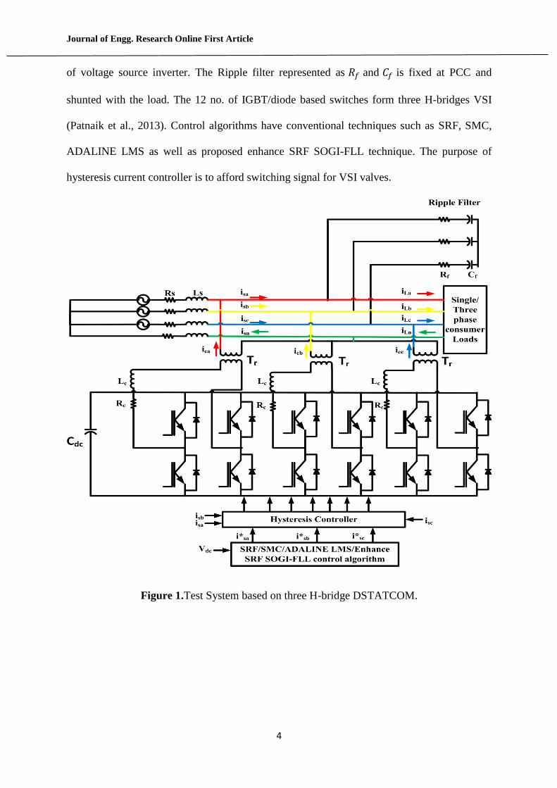
H-BRIDGE DSTATCOM
Figure1 illustrates the circuit arrangement of three H-bridge DSTATCOM attached to the
distribution system. The point on the distribution system at which H-bridge DSTATCOM is
bonded known as point of common coupling (PCC).𝐼𝑠𝑎,𝐼𝑠𝑏, and 𝐼𝑠𝑐 represent current from the
three phase AC mains. 𝐼𝐿𝑎,𝐼𝐿𝑏,𝐼𝐿𝑐 represent current from the load side. The parameter 𝑅𝑠 and
𝐿𝑠 are the resistance and inductance of the AC mains. 𝐼𝑐 and 𝑉𝑐 denote the injected current and
voltage respectively by the DSTATCOM. 𝑉𝑑𝑐 is the interior voltage of DC connect capacitor
Journal of Engg. Research Online First Article
4
of voltage source inverter. The Ripple filter represented as 𝑅𝑓 and 𝐶𝑓 is fixed at PCC and
shunted with the load. The 12 no. of IGBT/diode based switches form three H-bridges VSI
(Patnaik et al., 2013). Control algorithms have conventional techniques such as SRF, SMC,
ADALINE LMS as well as proposed enhance SRF SOGI-FLL technique. The purpose of
hysteresis current controller is to afford switching signal for VSI valves.
Figure 1.Test System based on three H-bridge DSTATCOM.
Journal of Engg. Research Online First Article
5
CONTROL PERFORMANCES
To generate the switching signals for the VSI switches of H-bridge DSTATCOM, control
performances such as SRF, SMC, ADALINE LMS and proposed enhance SRF SOGI-FLL
technique have been adopted. The discussion about the above control performances are
below:
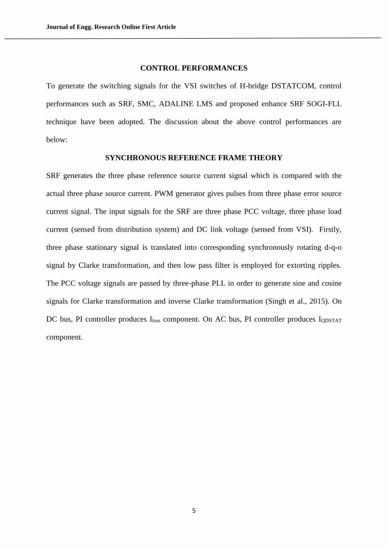
SYNCHRONOUS REFERENCE FRAME THEORY
SRF generates the three phase reference source current signal which is compared with the
actual three phase source current. PWM generator gives pulses from three phase error source
current signal. The input signals for the SRF are three phase PCC voltage, three phase load
current (sensed from distribution system) and DC link voltage (sensed from VSI). Firstly,
three phase stationary signal is translated into corresponding synchronously rotating d-q-o
signal by Clarke transformation, and then low pass filter is employed for extorting ripples.
The PCC voltage signals are passed by three-phase PLL in order to generate sine and cosine
signals for Clarke transformation and inverse Clarke transformation (Singh et al., 2015). On
DC bus, PI controller produces Iloss component. On AC bus, PI controller produces IQDSTAT
component.
Journal of Engg. Research Online First Article
6
Figure 2. Building block of synchronous reference frame.
The reference d-q current is given by
𝐼𝑑∗ = 𝐼𝑑𝐷𝐶 + 𝐼𝑙𝑜𝑠𝑠
𝐼𝑞∗ = 𝐼𝑞𝐷𝐶 + 𝐼𝑄𝐷𝑆𝑇𝐴𝑇 (1)
The Inverse Clarke transformation converts reference (d-q-0) current into reference (a-b-c)
current. The detail discussion on synchronous reference frame has been depicted in Figure 2.
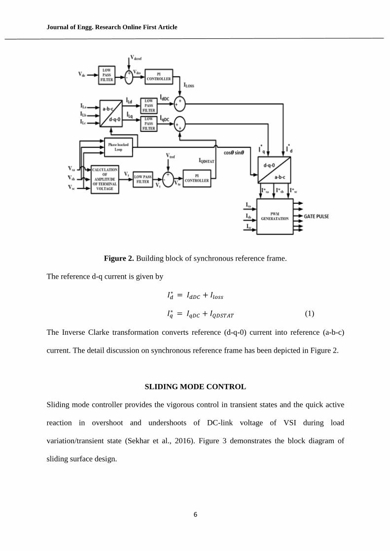
SLIDING MODE CONTROL
Sliding mode controller provides the vigorous control in transient states and the quick active
reaction in overshoot and undershoots of DC-link voltage of VSI during load
variation/transient state (Sekhar et al., 2016). Figure 3 demonstrates the block diagram of
sliding surface design.
Journal of Engg. Research Online First Article
7
Figure 3. Block diagram of sliding regime.
Calculation of In-phase current 𝐼𝑠𝑎𝑟𝑒𝑓
Actual DC voltage = 𝑉𝑑𝑐
Reference DC voltage = 𝑉𝑑𝑐𝑟𝑒𝑓
Step 1 Sliding Surface Design (Sekhar et al., 2016)
The LPF filtered actual Vdc and this is compared with reference DC voltage
𝑃1 = 𝑉𝑑𝑐𝑟𝑒𝑓 − 𝑉𝑑𝑐 (2)
P1= Error signal of reference and actual DC voltage
Step 2 Clauses of the sliding regime
Taking the derivative of Equation (2),
P2 = P1̇ =1
TS(P1 − P(n−1)) (3)
𝑃2= State variable and the derivative of error
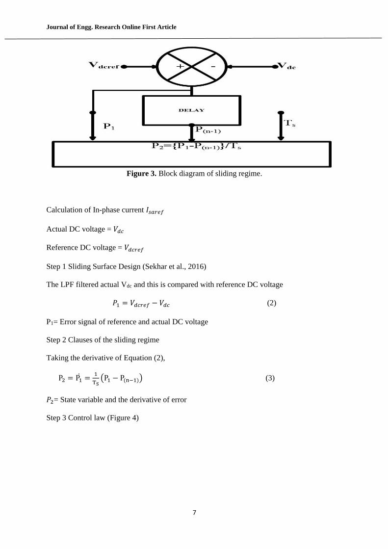
Step 3 Control law (Figure 4)
Journal of Engg. Research Online First Article
8
Figure 4. Block diagram of control law.
Now the switching constraints u and v are selected with the help of slope of DC link voltage
error
𝑢 = {+1, 𝑦𝑃1 > 0−1, 𝑦𝑃1 < 0
(4)
𝑣 = {+1, 𝑦𝑃2 > 0−1, 𝑦𝑃2 < 0
(5)
Now the reference DC currents
𝐼𝑑𝑐𝑟𝑒𝑓 = 𝐶𝑃1𝑢 + 𝐷𝑃2𝑣 (6)
𝑦 = 𝐴𝑃1 + 𝐵𝑃2 (7)
𝑦 = Switching hyper plane function
A, B, C, and D are the SMC constant
Instantaneous amplitude of PCC voltage
𝑉𝑡 = √2{𝑉𝑎
2+𝑉𝑏2+𝑉𝑐
2}
3 (8)
In- Phase component of Unit templates
𝑈𝑠𝑎𝑝 =𝑉𝑎
𝑉𝑡⁄ (9)
𝑈𝑠𝑏𝑝 =𝑉𝑏
𝑉𝑡⁄ (10)

Journal of Engg. Research Online First Article
9
𝑈𝑠𝑐𝑝 = 𝑉𝑐
𝑉𝑡⁄ (11)
Now, the quadrature component of Unit templates
𝑈𝑠𝑎𝑞 =(−𝑈𝑠𝑏𝑝 + 𝑈𝑠𝑐𝑝)
√3⁄ (12)
𝑈𝑠𝑏𝑞 =(𝑈𝑠𝑎𝑝√3 + 𝑈𝑠𝑏𝑝 − 𝑈𝑠𝑐𝑝)
2⁄ (13)
𝑈𝑠𝑐𝑞 =(−𝑈𝑠𝑎𝑝√3 + 𝑈𝑠𝑏𝑝 − 𝑈𝑠𝑐𝑝)
2⁄ (14)
Now, the reference In –Phase component of active power of source current
𝐼∗𝑠𝑎𝑝 = 𝐼𝑑𝑐𝑟𝑒𝑓𝑈𝑠𝑎𝑝 (15)
𝐼∗𝑠𝑏𝑝 = 𝐼𝑑𝑐𝑟𝑒𝑓𝑈𝑠𝑏𝑝 (16)
𝐼∗𝑠𝑐𝑝 = 𝐼𝑑𝑐𝑟𝑒𝑓𝑈𝑠𝑐𝑝 (17)
The error in PCC voltage evaluated as
𝑉𝑎𝑐𝑒 = 𝑉∗𝑡 − 𝑉𝑡 (18)
The PI controller creates output for keeping PCC voltage at reference value
𝐼𝑎𝑐𝑟𝑒𝑓(𝑘) = 𝐼𝑎𝑐𝑟𝑒𝑓(𝑘 − 1) + 𝐾𝑝𝑎{𝑉𝑎𝑐𝑒(𝑘) + 𝑉𝑎𝑐𝑒(𝑘 − 1)} + 𝐾𝑖𝑎𝑉𝑎𝑐𝑒(𝑘) (19)
Where,
𝑉𝑎𝑐𝑒(𝑘) =Kth time voltage error
𝑉𝑎𝑐𝑒(𝑘 − 1) = (K-1)th time voltage error
𝐾𝑝𝑎= Proportional gain of PI controller, 𝐾𝑖𝑎 =Integral gain of PI controller
Now, the reference quadrature –phase component of source current
𝐼∗𝑠𝑎𝑞 = 𝐼𝑎𝑐𝑟𝑒𝑓𝑈𝑠𝑎𝑞 (20)
𝐼∗𝑠𝑏𝑞 = 𝐼𝑎𝑐𝑟𝑒𝑓𝑈𝑠𝑏𝑞 (21)
𝐼∗𝑠𝑐𝑞 = 𝐼𝑎𝑐𝑟𝑒𝑓𝑈𝑠𝑐𝑞 (22)
The total three phase reference source current is the addition of In –phase and quadrature
phase component as
Journal of Engg. Research Online First Article
10
𝐼𝑆𝑎∗ = 𝐼𝑆𝑎𝑝
∗ + 𝐼𝑆𝑎𝑞∗ (23)
𝐼𝑆𝑏∗ = 𝐼𝑆𝑏𝑝
∗ + 𝐼𝑆𝑏𝑞∗ (24)
𝐼𝑆𝑐∗ = 𝐼𝑆𝑐𝑝
∗ + 𝐼𝑆𝑐𝑞∗ (25)
ADALINE LMS CONTROL
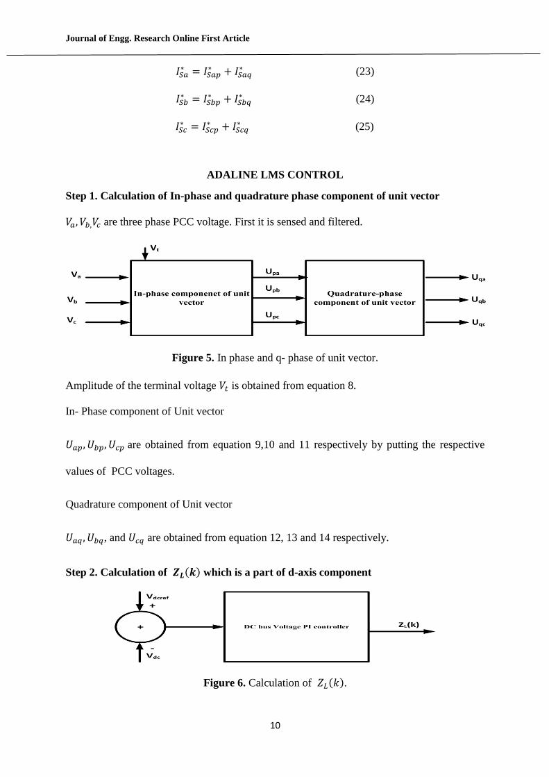
Step 1. Calculation of In-phase and quadrature phase component of unit vector
𝑉𝑎, 𝑉𝑏,𝑉𝑐 are three phase PCC voltage. First it is sensed and filtered.
Figure 5. In phase and q- phase of unit vector.
Amplitude of the terminal voltage 𝑉𝑡 is obtained from equation 8.
In- Phase component of Unit vector
𝑈𝑎𝑝, 𝑈𝑏𝑝, 𝑈𝑐𝑝 are obtained from equation 9,10 and 11 respectively by putting the respective
values of PCC voltages.
Quadrature component of Unit vector
𝑈𝑎𝑞 , 𝑈𝑏𝑞, and 𝑈𝑐𝑞 are obtained from equation 12, 13 and 14 respectively.
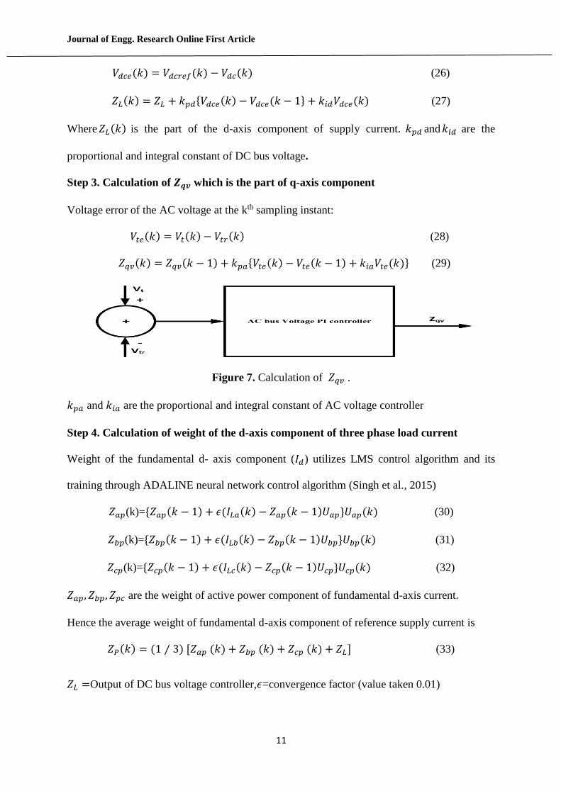
Step 2. Calculation of 𝒁𝑳(𝒌) which is a part of d-axis component
Figure 6. Calculation of 𝑍𝐿(𝑘).
Journal of Engg. Research Online First Article
11
𝑉𝑑𝑐𝑒(𝑘) = 𝑉𝑑𝑐𝑟𝑒𝑓(𝑘) − 𝑉𝑑𝑐(𝑘) (26)
𝑍𝐿(𝑘) = 𝑍𝐿 + 𝑘𝑝𝑑{𝑉𝑑𝑐𝑒(𝑘) − 𝑉𝑑𝑐𝑒(𝑘 − 1} + 𝑘𝑖𝑑𝑉𝑑𝑐𝑒(𝑘) (27)
Where 𝑍𝐿(𝑘) is the part of the d-axis component of supply current. 𝑘𝑝𝑑 and 𝑘𝑖𝑑 are the
proportional and integral constant of DC bus voltage.
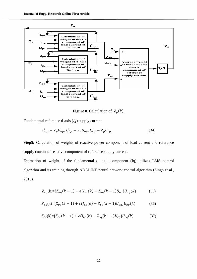
Step 3. Calculation of 𝒁𝒒𝒗 which is the part of q-axis component
Voltage error of the AC voltage at the kth sampling instant:
𝑉𝑡𝑒(𝑘) = 𝑉𝑡(𝑘) − 𝑉𝑡𝑟(𝑘) (28)
𝑍𝑞𝑣(𝑘) = 𝑍𝑞𝑣(𝑘 − 1) + 𝑘𝑝𝑎{𝑉𝑡𝑒(𝑘) − 𝑉𝑡𝑒(𝑘 − 1) + 𝑘𝑖𝑎𝑉𝑡𝑒(𝑘)} (29)
Figure 7. Calculation of 𝑍𝑞𝑣 .
𝑘𝑝𝑎 and 𝑘𝑖𝑎 are the proportional and integral constant of AC voltage controller
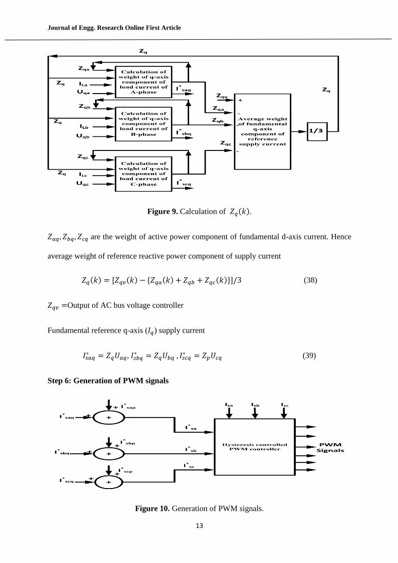
Step 4. Calculation of weight of the d-axis component of three phase load current
Weight of the fundamental d- axis component (𝐼𝑑) utilizes LMS control algorithm and its
training through ADALINE neural network control algorithm (Singh et al., 2015)
𝑍𝑎𝑝(k)={𝑍𝑎𝑝(𝑘 − 1) + 𝜖(𝐼𝐿𝑎(𝑘) − 𝑍𝑎𝑝(𝑘 − 1)𝑈𝑎𝑝}𝑈𝑎𝑝(𝑘) (30)
𝑍𝑏𝑝(k)={𝑍𝑏𝑝(𝑘 − 1) + 𝜖(𝐼𝐿𝑏(𝑘) − 𝑍𝑏𝑝(𝑘 − 1)𝑈𝑏𝑝}𝑈𝑏𝑝(𝑘) (31)
𝑍𝑐𝑝(k)={𝑍𝑐𝑝(𝑘 − 1) + 𝜖(𝐼𝐿𝑐(𝑘) − 𝑍𝑐𝑝(𝑘 − 1)𝑈𝑐𝑝}𝑈𝑐𝑝(𝑘) (32)
𝑍𝑎𝑝, 𝑍𝑏𝑝, 𝑍𝑝𝑐 are the weight of active power component of fundamental d-axis current.
Hence the average weight of fundamental d-axis component of reference supply current is
𝑍𝑃(𝑘) = (1 ⁄ 3) [𝑍𝑎𝑝 (𝑘) + 𝑍𝑏𝑝 (𝑘) + 𝑍𝑐𝑝 (𝑘) + 𝑍𝐿] (33)
𝑍𝐿 =Output of DC bus voltage controller,𝜖=convergence factor (value taken 0.01)
Journal of Engg. Research Online First Article
12
Figure 8. Calculation of 𝑍𝑝(𝑘).
Fundamental reference d-axis (𝐼𝑑) supply current
𝐼𝑠𝑎𝑝∗ = 𝑍𝑝𝑈𝑎𝑝, 𝐼𝑠𝑏𝑝
∗ = 𝑍𝑝𝑈𝑏𝑝, 𝐼𝑠𝑐𝑝∗ = 𝑍𝑝𝑈𝑐𝑝 (34)
Step5: Calculation of weights of reactive power component of load current and reference
supply current of reactive component of reference supply current.
Estimation of weight of the fundamental q- axis component (Iq) utilizes LMS control
algorithm and its training through ADALINE neural network control algorithm (Singh et al.,
2015).
𝑍𝑎𝑞(k)={𝑍𝑎𝑞(𝑘 − 1) + 𝜖(𝐼𝐿𝑎(𝑘) − 𝑍𝑎𝑞(𝑘 − 1)𝑈𝑎𝑞}𝑈𝑎𝑞(𝑘) (35)
𝑍𝑏𝑞(k)={𝑍𝑏𝑞(𝑘 − 1) + 𝜖(𝐼𝐿𝑏(𝑘) − 𝑍𝑏𝑞(𝑘 − 1)𝑈𝑏𝑞}𝑈𝑏𝑞(𝑘) (36)
𝑍𝑐𝑞(k)={𝑍𝑐𝑞(𝑘 − 1) + 𝜖(𝐼𝐿𝑐(𝑘) − 𝑍𝑐𝑞(𝑘 − 1)𝑈𝑐𝑞}𝑈𝑐𝑞(𝑘) (37)
Journal of Engg. Research Online First Article
13
Figure 9. Calculation of 𝑍𝑞(𝑘).
𝑍𝑎𝑞 , 𝑍𝑏𝑞 , 𝑍𝑐𝑞 are the weight of active power component of fundamental d-axis current. Hence
average weight of reference reactive power component of supply current
𝑍𝑞(𝑘) = [𝑍𝑞𝑣(𝑘) − {𝑍𝑞𝑎(𝑘) + 𝑍𝑞𝑏 + 𝑍𝑞𝑐(𝑘)}]/3 (38)
𝑍𝑞𝑣 =Output of AC bus voltage controller
Fundamental reference q-axis (𝐼𝑞) supply current
𝐼𝑠𝑎𝑞∗ = 𝑍𝑞𝑈𝑎𝑞, 𝐼𝑠𝑏𝑞
∗ = 𝑍𝑞𝑈𝑏𝑞 , 𝐼𝑠𝑐𝑞∗ = 𝑍𝑝𝑈𝑐𝑞 (39)
Step 6: Generation of PWM signals
Figure 10. Generation of PWM signals.
Journal of Engg. Research Online First Article
14
The three phase reference supply current is
𝐼𝑠𝑎∗ = 𝐼𝑠𝑎𝑝
∗ + 𝐼𝑠𝑎𝑞∗ (40)
𝐼𝑠𝑏∗ = 𝐼𝑠𝑏𝑝
∗ + 𝐼𝑠𝑏𝑞∗ (41)
𝐼𝑠𝑐∗ = 𝐼𝑠𝑐𝑝
∗ + 𝐼𝑠𝑐𝑞∗ (42)
These calculated reference supply currents (𝐼𝑠𝑎∗ , 𝐼𝑠𝑏
∗ , 𝐼𝑠𝑐∗ ) are compared with the sensed supply
currents (𝐼𝑠𝑎, 𝐼𝑠𝑏 , 𝐼𝑠𝑐) to achieve current error which produce gating signal pulses for VSI
switches of DSTATCOM.
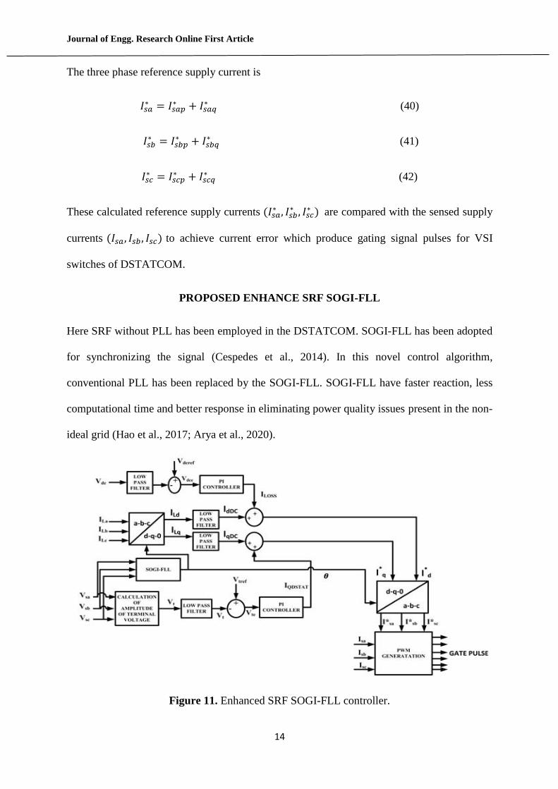
PROPOSED ENHANCE SRF SOGI-FLL
Here SRF without PLL has been employed in the DSTATCOM. SOGI-FLL has been adopted
for synchronizing the signal (Cespedes et al., 2014). In this novel control algorithm,
conventional PLL has been replaced by the SOGI-FLL. SOGI-FLL have faster reaction, less
computational time and better response in eliminating power quality issues present in the non-
ideal grid (Hao et al., 2017; Arya et al., 2020).
Figure 11. Enhanced SRF SOGI-FLL controller.
Journal of Engg. Research Online First Article
15
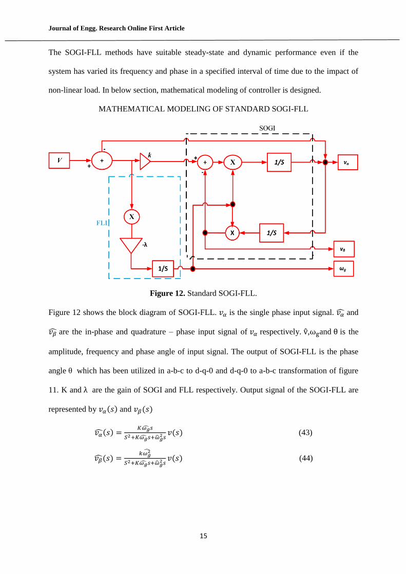
The SOGI-FLL methods have suitable steady-state and dynamic performance even if the
system has varied its frequency and phase in a specified interval of time due to the impact of
non-linear load. In below section, mathematical modeling of controller is designed.
MATHEMATICAL MODELING OF STANDARD SOGI-FLL
Figure 12. Standard SOGI-FLL.
Figure 12 shows the block diagram of SOGI-FLL. 𝑣𝛼 is the single phase input signal. 𝑣�̂� and
𝑣�̂� are the in-phase and quadrature – phase input signal of 𝑣𝛼 respectively. v̂,ωgand θ is the
amplitude, frequency and phase angle of input signal. The output of SOGI-FLL is the phase
angle θ which has been utilized in a-b-c to d-q-0 and d-q-0 to a-b-c transformation of figure
11. K and λ are the gain of SOGI and FLL respectively. Output signal of the SOGI-FLL are
represented by 𝑣𝛼(𝑠) and 𝑣𝛽(𝑠)
𝑣�̂�(𝑠) =𝐾𝜔�̂�𝑠
𝑆2+𝐾𝜔�̂�𝑠+�̂�𝑔2 𝑠
𝑣(𝑠) (43)
𝑣�̂�(𝑠) =𝑘𝜔𝑔
2̂
𝑆2+𝐾𝜔�̂�𝑠+�̂�𝑔2𝑠
𝑣(𝑠) (44)
Journal of Engg. Research Online First Article
16
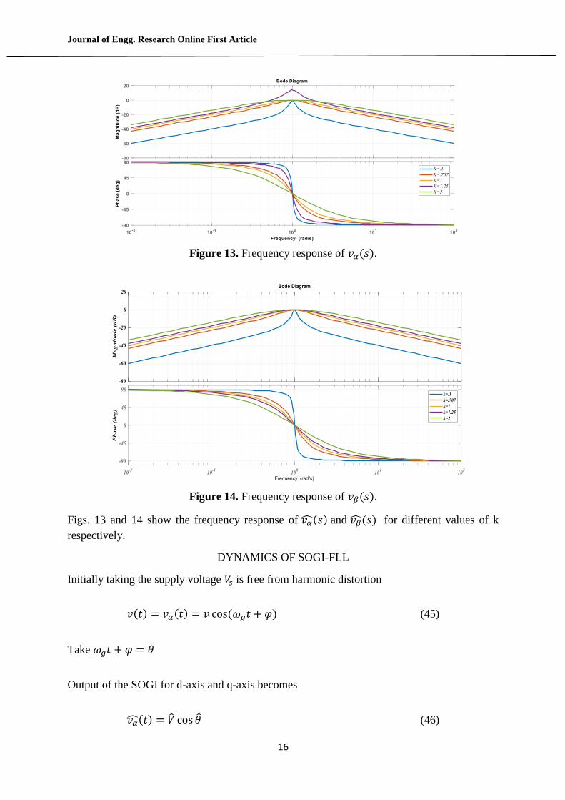
Figure 13. Frequency response of 𝑣𝛼(𝑠).
Figure 14. Frequency response of 𝑣𝛽(𝑠).
Figs. 13 and 14 show the frequency response of 𝑣�̂�(𝑠) and 𝑣�̂�(𝑠) for different values of k
respectively.
DYNAMICS OF SOGI-FLL
Initially taking the supply voltage 𝑉𝑠 is free from harmonic distortion
𝑣(𝑡) = 𝑣𝛼(𝑡) = 𝑣 cos(𝜔𝑔𝑡 + 𝜑) (45)
Take 𝜔𝑔𝑡 + 𝜑 = 𝜃
Output of the SOGI for d-axis and q-axis becomes
𝑣�̂�(𝑡) = �̂� cos 𝜃 (46)
Journal of Engg. Research Online First Article
17
𝑣�̂�(𝑡) = �̂� sin 𝜃 (47)
𝑣 and 𝜃 are the amplitude and phase angle of input supply voltage respectively. Assuming
SOGI-FLL is in quasi locked state,𝑣 ≅ 𝑣 ,𝜃 ≅ 𝜃. (In the steady state they are very close to
v and θ respectively).This is the basic linearization concept of FLL.
Differential equation obtained from figure
𝑣�̇̂� = 𝜔�̂�[𝑘(𝑣𝛼 − 𝑣�̂�) − 𝑣�̂�] (48)
𝑣�̇̂� = 𝜔�̂�𝑣�̂� (49)
𝜔�̇̂� = −𝜆
𝑣2 (𝑣𝛼 − 𝑣𝛼 )̂𝑣�̂� (50)
Substituting the value of 𝑣𝛼 and 𝑣�̂�
𝜔�̇̂� =𝜆
𝑣2 [𝑣 cos 𝜃 − 𝑣 cos 𝜃]̂ sin 𝜃 (51)
=𝜆
2𝑣[𝑣 sin(𝜃 − 𝜃)̂ + 𝑣 sin 2�̂� − 𝑣 sin(𝜃 + 𝜃) (52)
Assume sin(𝜃 − 𝜃)̂ ≅ (𝜃 − 𝜃)̂, 𝑣 sin 2�̂� − 𝑣 sin(𝜃 + 𝜃) ≅ 0
From above assumption equation becomes
=𝜆
2𝑣[𝑣(𝜃 − 𝜃]̂ (53)
=𝜆
2[(𝜃 − 𝜃]̂ (54)
Phase angle 𝜃 determined from SOGI-FLL structure
𝜃 = tan−1 𝑣𝛽
𝑣𝛼 (55)
Differentiating w.r.t. time yields �̇� =𝑣𝛼𝑣�̇̂�−𝑣�̇̂�𝑣𝛽
𝑣𝛼2̂+𝑣𝛽
2̂
Journal of Engg. Research Online First Article
18
�̇� =𝑣𝛼𝑣�̇̂�−𝑣�̇̂�𝑣𝛽
𝑉 2̇̂ (56)
Consider 𝑣𝛼2̂ + 𝑣𝛽
2̂ = �̂�2
Substitute the value of 𝑣𝛼 and 𝑣𝛽 in equation (56)
�̇� =(𝑣𝛼
2 + 𝑣𝛽2)𝜔�̂� − 𝑘𝜔�̂�(𝑣𝛼 − 𝑣�̂�)𝑣�̂�
�̂�2
Consider(𝑣𝛼 − 𝑣�̂�)𝑣�̂� =−𝜔�̇̂�𝑉 2̇̂
𝜆⁄
𝜔�̇̂� = 𝜔𝑔 + (𝑘�̂�𝑔
𝜆)𝜔�̇̂� (57)
Coefficient of𝑘�̂�𝑔
𝜆i.e.𝜔�̇̂� is grid frequency which is time dependent parameter. So, Laplace
transform of equation (57) is not possible. Hence, for getting the linear model estimated
coefficient of time dependent frequency is approximated to its nominal value
𝜔�̇̂� = 𝜔𝑔 + (𝑘�̂�𝑛
𝜆)𝜔�̇̂� (58)
Now from figure, estimated amplitude for supply voltage
�̂� = √𝑣𝛼2 + 𝑣𝛽
2 (59)
Differentiating above equation w.r.t time yields
�̇̂� =𝑣�̂�𝑣�̇̂� + 𝑣�̂�𝑣�̇̂�
√𝑣𝛼2 + 𝑣𝛽
2
�̇̂� =𝑣�̂�𝑣�̇̂�+𝑣�̂�𝑣�̇̂�
𝑉 (60)
Put the value of 𝑣�̂� and 𝑣�̂� in Equation (60)
Journal of Engg. Research Online First Article
19
�̇̂� =𝑘𝜔𝑔(𝑣𝛼 − 𝑣𝛼)�̂�𝛼
�̂�
�̇̂� =𝑘𝜔𝑔[𝑉 cos 𝜃−𝑉 cos �̂�]𝑉 cos �̂�
𝑉 (61)
= 𝑘𝜔𝑔
2{𝑉 cos(𝜃 − 𝜃) + {𝑉 cos(𝜃 + 𝜃) − �̂� cos(2𝜃) − �̂�} (62)
Consider cos(𝜃 − 𝜃) = 1, 𝑉 cos(𝜃 + 𝜃)̂ − �̂� cos 2𝜃 = 0
�̂� ≅𝑘𝜔𝑔
2(𝑉 − �̂�) (63)
Coefficient of 𝑘
2 i.e.𝜔𝑔 is grid frequency which is time dependent parameter. So, Laplace
transform of equation (63) is not possible. For getting the linear model estimated coefficient
of time dependent frequency is approximated to its nominal value
�̂� ≅𝑘𝜔𝑛
2(𝑉 − �̂�) (64)
Based on the above linearization model, approximated magnitude of supply voltage, phase
angle, and angular frequency are obtained as:
�̂�(𝑠) =𝑘𝜔𝑛
2⁄
𝑆+𝑘𝜔𝑛
2⁄𝑉(𝑠) (65)
𝜃(𝑠) =(
𝑘𝜔𝑛2⁄ )𝑠+𝜆
2⁄
𝑠2+(𝑘𝜔𝑛
2⁄ )𝑠+𝜆2⁄
𝜃(𝑠) (66)
𝜔�̂�(𝑠) =𝜆
2⁄
𝑠2+(𝑘𝜔𝑛
2⁄ )𝑠+𝜆2⁄
𝜔𝑔(𝑠) (67)
Modeling of Tuning Parameters
Characteristics equation obtained from equation (67)
= 𝑠2 + (𝑘𝜔𝑛
2⁄ ) 𝑠 + 𝜆2⁄ (68)
Journal of Engg. Research Online First Article
20
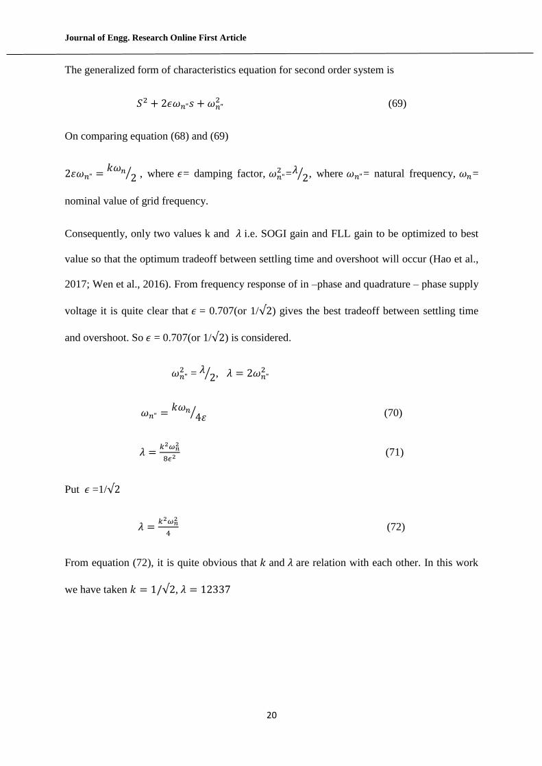
The generalized form of characteristics equation for second order system is
𝑆2 + 2𝜖𝜔𝑛"𝑠 + 𝜔𝑛"2 (69)
On comparing equation (68) and (69)
2𝜀𝜔𝑛" =𝑘𝜔𝑛
2⁄ , where 𝜖= damping factor, 𝜔𝑛"2 =𝜆
2⁄ , where 𝜔𝑛"= natural frequency, 𝜔𝑛=
nominal value of grid frequency.
Consequently, only two values k and 𝜆 i.e. SOGI gain and FLL gain to be optimized to best
value so that the optimum tradeoff between settling time and overshoot will occur (Hao et al.,
2017; Wen et al., 2016). From frequency response of in –phase and quadrature – phase supply
voltage it is quite clear that 𝜖 = 0.707(or 1/√2) gives the best tradeoff between settling time
and overshoot. So 𝜖 = 0.707(or 1/√2) is considered.
𝜔𝑛"2 = 𝜆 2⁄ , 𝜆 = 2𝜔𝑛"
2
𝜔𝑛" =𝑘𝜔𝑛
4𝜀⁄ (70)
𝜆 =𝑘2𝜔𝑛
2
8𝜖2 (71)
Put 𝜖 =1/√2
𝜆 =𝑘2𝜔𝑛
2
4 (72)
From equation (72), it is quite obvious that 𝑘 and 𝜆 are relation with each other. In this work
we have taken 𝑘 = 1/√2, 𝜆 = 12337
Journal of Engg. Research Online First Article
21
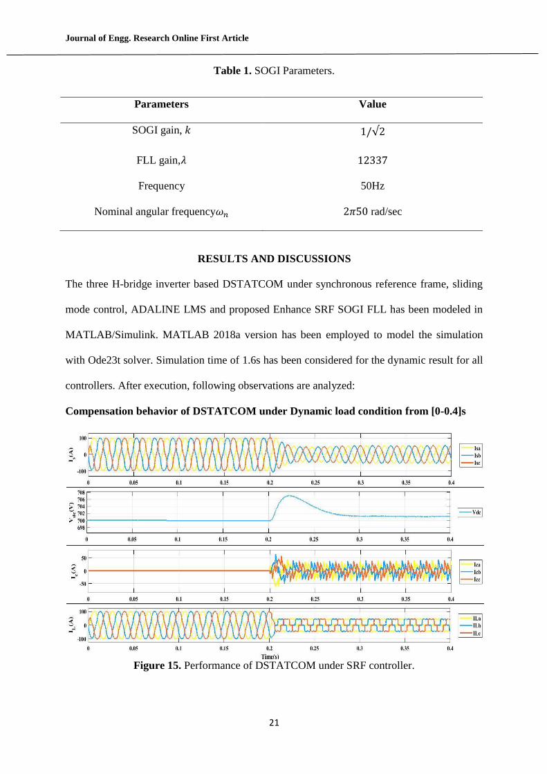
Table 1. SOGI Parameters.
Parameters Value
SOGI gain, 𝑘 1/√2
FLL gain,𝜆 12337
Frequency 50Hz
Nominal angular frequency𝜔𝑛 2𝜋50 rad/sec
RESULTS AND DISCUSSIONS
The three H-bridge inverter based DSTATCOM under synchronous reference frame, sliding
mode control, ADALINE LMS and proposed Enhance SRF SOGI FLL has been modeled in
MATLAB/Simulink. MATLAB 2018a version has been employed to model the simulation
with Ode23t solver. Simulation time of 1.6s has been considered for the dynamic result for all
controllers. After execution, following observations are analyzed:
Compensation behavior of DSTATCOM under Dynamic load condition from [0-0.4]s
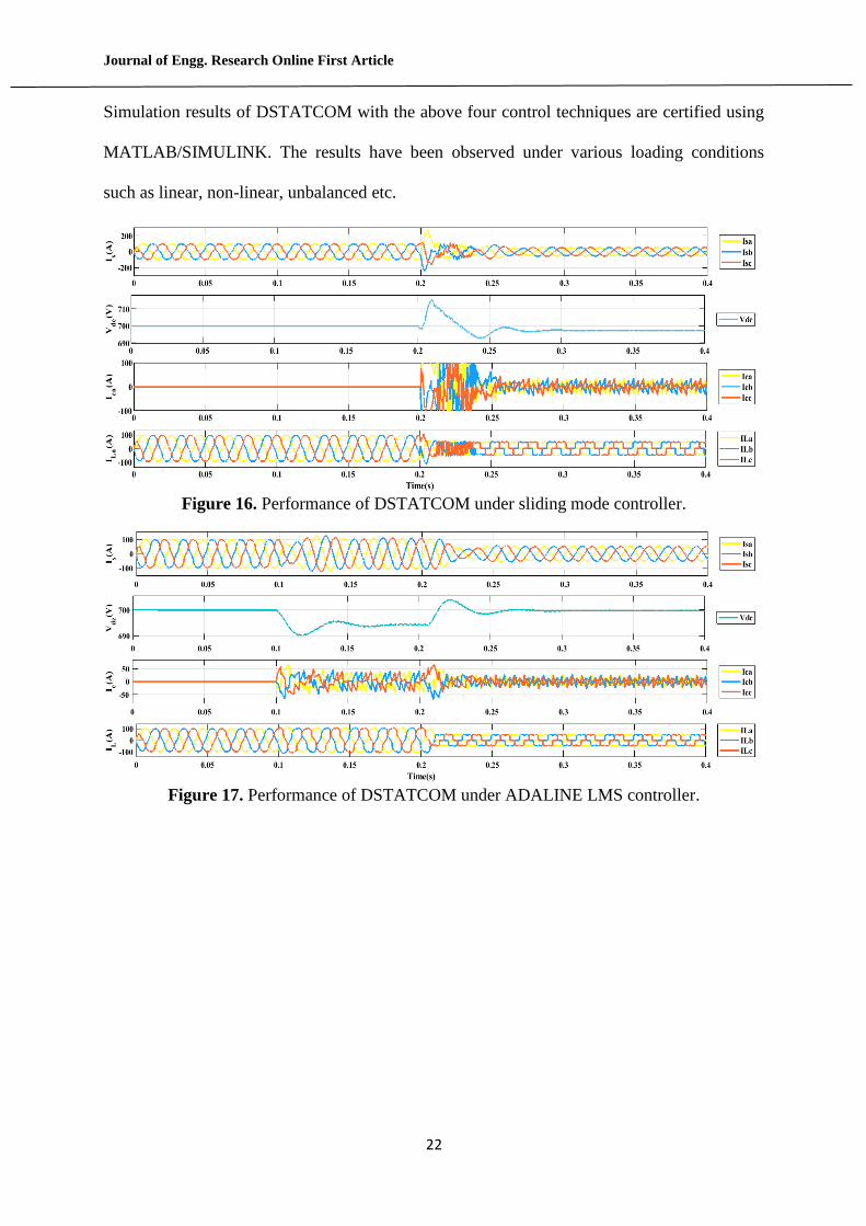
Figure 15. Performance of DSTATCOM under SRF controller.
Journal of Engg. Research Online First Article
22
Simulation results of DSTATCOM with the above four control techniques are certified using
MATLAB/SIMULINK. The results have been observed under various loading conditions
such as linear, non-linear, unbalanced etc.
Figure 16. Performance of DSTATCOM under sliding mode controller.
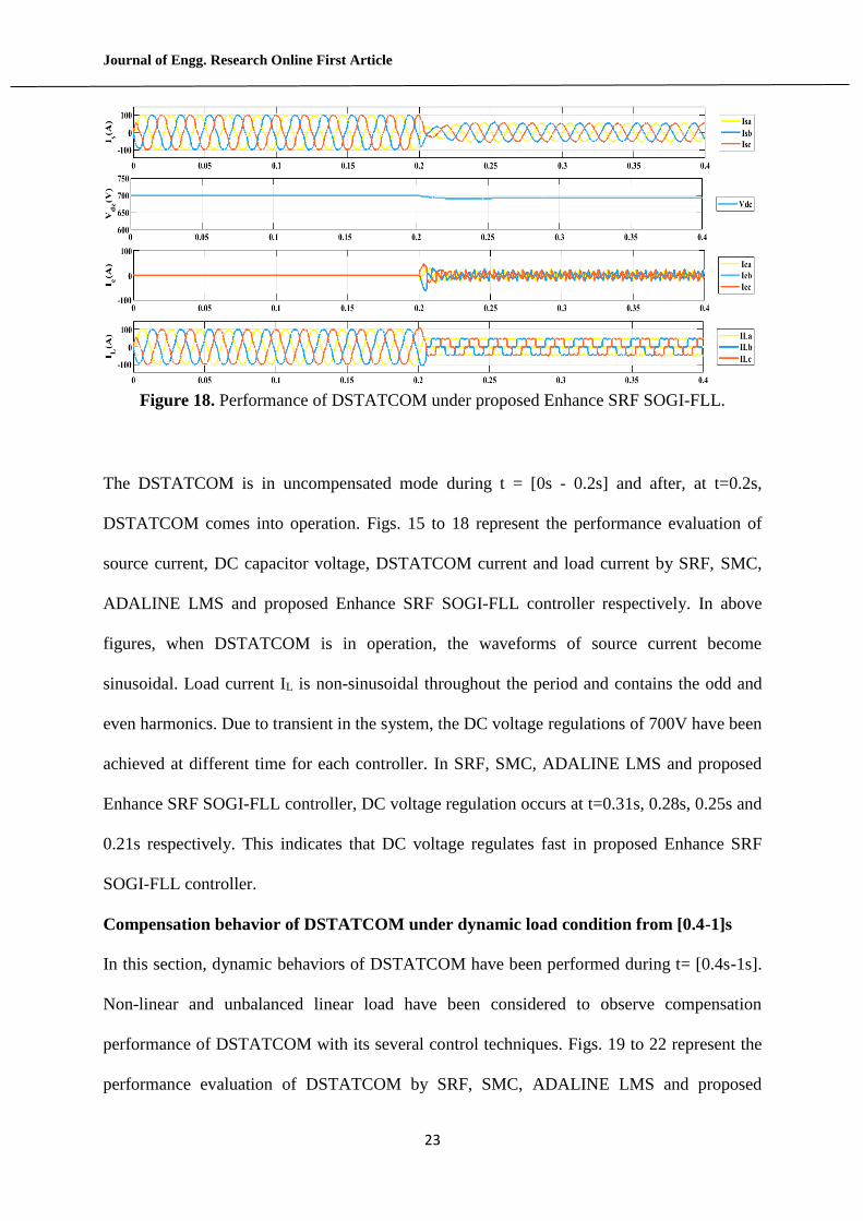
Figure 17. Performance of DSTATCOM under ADALINE LMS controller.
Journal of Engg. Research Online First Article
23
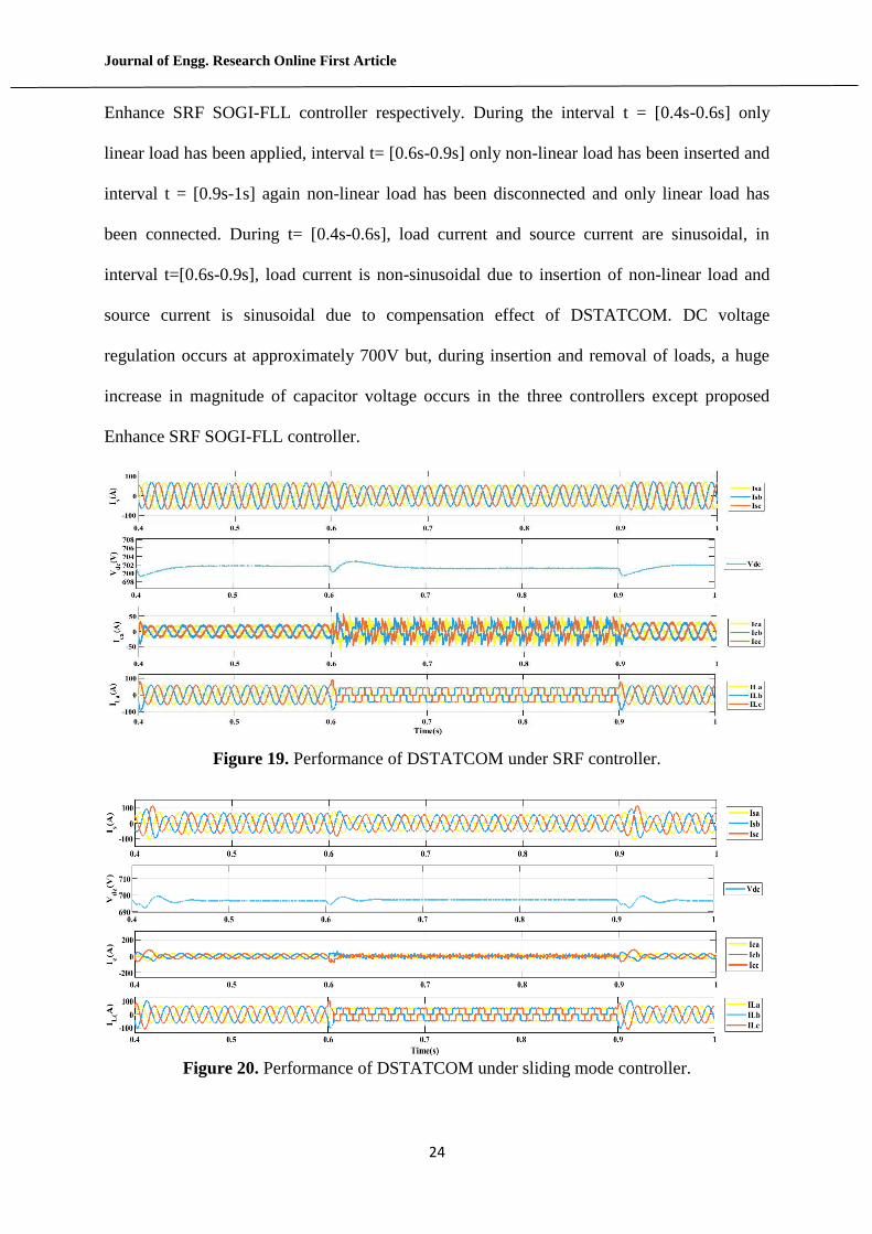
Figure 18. Performance of DSTATCOM under proposed Enhance SRF SOGI-FLL.
The DSTATCOM is in uncompensated mode during t = [0s - 0.2s] and after, at t=0.2s,
DSTATCOM comes into operation. Figs. 15 to 18 represent the performance evaluation of
source current, DC capacitor voltage, DSTATCOM current and load current by SRF, SMC,
ADALINE LMS and proposed Enhance SRF SOGI-FLL controller respectively. In above
figures, when DSTATCOM is in operation, the waveforms of source current become
sinusoidal. Load current IL is non-sinusoidal throughout the period and contains the odd and
even harmonics. Due to transient in the system, the DC voltage regulations of 700V have been
achieved at different time for each controller. In SRF, SMC, ADALINE LMS and proposed
Enhance SRF SOGI-FLL controller, DC voltage regulation occurs at t=0.31s, 0.28s, 0.25s and
0.21s respectively. This indicates that DC voltage regulates fast in proposed Enhance SRF
SOGI-FLL controller.
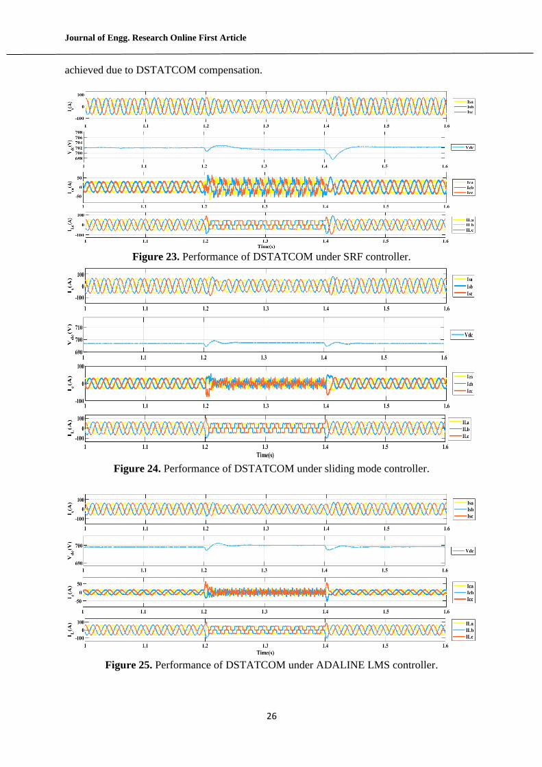
Compensation behavior of DSTATCOM under dynamic load condition from [0.4-1]s
In this section, dynamic behaviors of DSTATCOM have been performed during t= [0.4s-1s].
Non-linear and unbalanced linear load have been considered to observe compensation
performance of DSTATCOM with its several control techniques. Figs. 19 to 22 represent the
performance evaluation of DSTATCOM by SRF, SMC, ADALINE LMS and proposed
Journal of Engg. Research Online First Article
24
Enhance SRF SOGI-FLL controller respectively. During the interval t = [0.4s-0.6s] only
linear load has been applied, interval t= [0.6s-0.9s] only non-linear load has been inserted and
interval t = [0.9s-1s] again non-linear load has been disconnected and only linear load has
been connected. During t= [0.4s-0.6s], load current and source current are sinusoidal, in
interval t=[0.6s-0.9s], load current is non-sinusoidal due to insertion of non-linear load and
source current is sinusoidal due to compensation effect of DSTATCOM. DC voltage
regulation occurs at approximately 700V but, during insertion and removal of loads, a huge
increase in magnitude of capacitor voltage occurs in the three controllers except proposed
Enhance SRF SOGI-FLL controller.
Figure 19. Performance of DSTATCOM under SRF controller.
Figure 20. Performance of DSTATCOM under sliding mode controller.

Journal of Engg. Research Online First Article
25
Figure 21. Performance of DSTATCOM under ADALINE LMS controller.
Figure 22. Performance of DSTATCOM under proposed Enhance SRF SOGI-FLL.
This increase in DC capacitor voltage will suddenly increase the reactive power demand and
creates burden in the source side. It has been also observed that DSTATCOM current is
sinusoidal for linear load while DSTATCOM current is non-sinusoidal for non-linear load.
Compensation behavior of DSTATCOM under dynamic load condition from [1s-1.6s]
In this section, dynamic behaviors of DSTATCOM have been studied during t = [1s-1.6s].
Figs 23-26 represent the performance of DSTATCOM by SRF, SMC, ADALINE LMS and
proposed enhance SRF SOGI-FLL controller respectively. During t = [1s-1.2s], linear load
has been employed hence wave form of source current, DSTATCOM current, and load
current are sinusoidal. In the interval t = [1.2s-1.4s], non-sinusoidal waveform occurs in load
current and DSTATCOM current while sinusoidal waveform of source current has been
Journal of Engg. Research Online First Article
26
achieved due to DSTATCOM compensation.
Figure 23. Performance of DSTATCOM under SRF controller.
Figure 24. Performance of DSTATCOM under sliding mode controller.
Figure 25. Performance of DSTATCOM under ADALINE LMS controller.
Journal of Engg. Research Online First Article
27
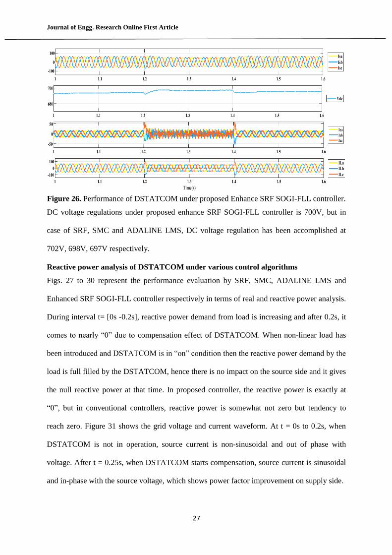
Figure 26. Performance of DSTATCOM under proposed Enhance SRF SOGI-FLL controller.
DC voltage regulations under proposed enhance SRF SOGI-FLL controller is 700V, but in
case of SRF, SMC and ADALINE LMS, DC voltage regulation has been accomplished at
702V, 698V, 697V respectively.
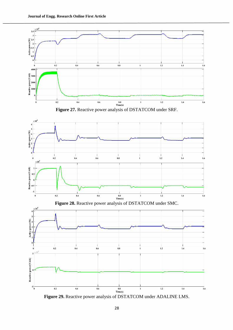
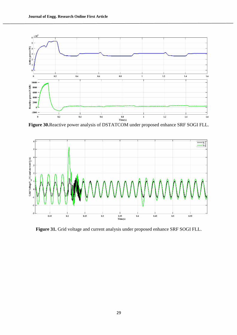
Reactive power analysis of DSTATCOM under various control algorithms
Figs. 27 to 30 represent the performance evaluation by SRF, SMC, ADALINE LMS and
Enhanced SRF SOGI-FLL controller respectively in terms of real and reactive power analysis.
During interval t= [0s -0.2s], reactive power demand from load is increasing and after 0.2s, it
comes to nearly “0” due to compensation effect of DSTATCOM. When non-linear load has
been introduced and DSTATCOM is in “on” condition then the reactive power demand by the
load is full filled by the DSTATCOM, hence there is no impact on the source side and it gives
the null reactive power at that time. In proposed controller, the reactive power is exactly at
“0”, but in conventional controllers, reactive power is somewhat not zero but tendency to
reach zero. Figure 31 shows the grid voltage and current waveform. At t = 0s to 0.2s, when
DSTATCOM is not in operation, source current is non-sinusoidal and out of phase with
voltage. After t = 0.25s, when DSTATCOM starts compensation, source current is sinusoidal
and in-phase with the source voltage, which shows power factor improvement on supply side.
Journal of Engg. Research Online First Article
28
Figure 27. Reactive power analysis of DSTATCOM under SRF.
Figure 28. Reactive power analysis of DSTATCOM under SMC.
Figure 29. Reactive power analysis of DSTATCOM under ADALINE LMS.
Journal of Engg. Research Online First Article
29
Figure 30.Reactive power analysis of DSTATCOM under proposed enhance SRF SOGI FLL.
Figure 31. Grid voltage and current analysis under proposed enhance SRF SOGI FLL.
Journal of Engg. Research Online First Article
30
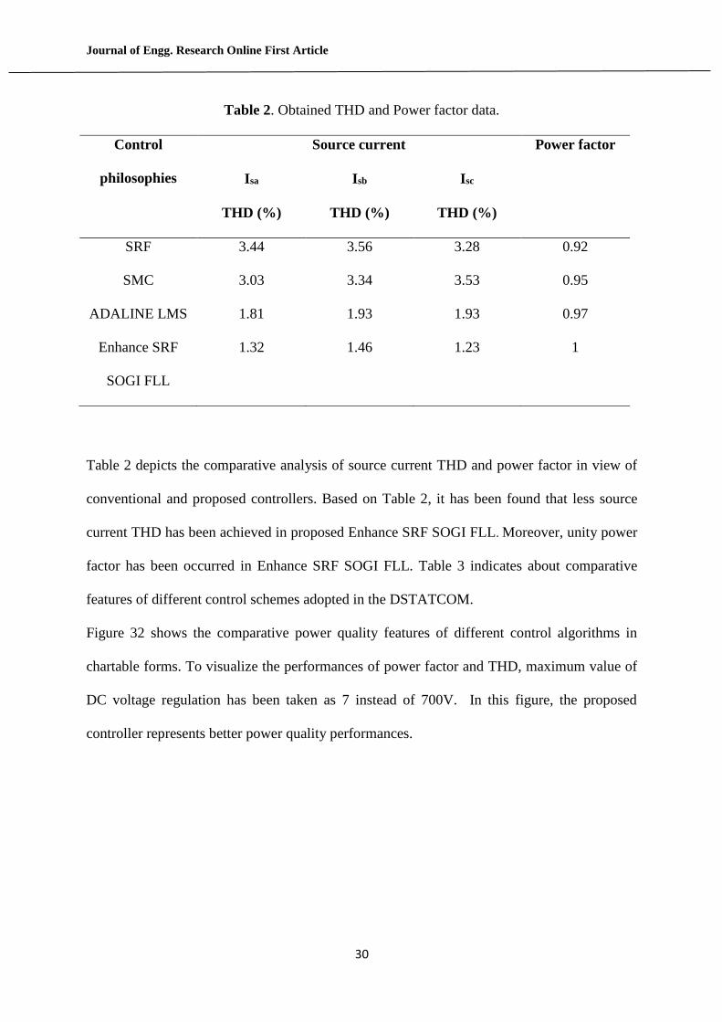
Table 2. Obtained THD and Power factor data.
Control
philosophies
Source current Power factor
Isa Isb Isc
THD (%) THD (%) THD (%)
SRF 3.44 3.56 3.28 0.92
SMC 3.03 3.34 3.53 0.95
ADALINE LMS 1.81 1.93 1.93 0.97
Enhance SRF
SOGI FLL
1.32 1.46 1.23 1
Table 2 depicts the comparative analysis of source current THD and power factor in view of
conventional and proposed controllers. Based on Table 2, it has been found that less source
current THD has been achieved in proposed Enhance SRF SOGI FLL. Moreover, unity power
factor has been occurred in Enhance SRF SOGI FLL. Table 3 indicates about comparative
features of different control schemes adopted in the DSTATCOM.
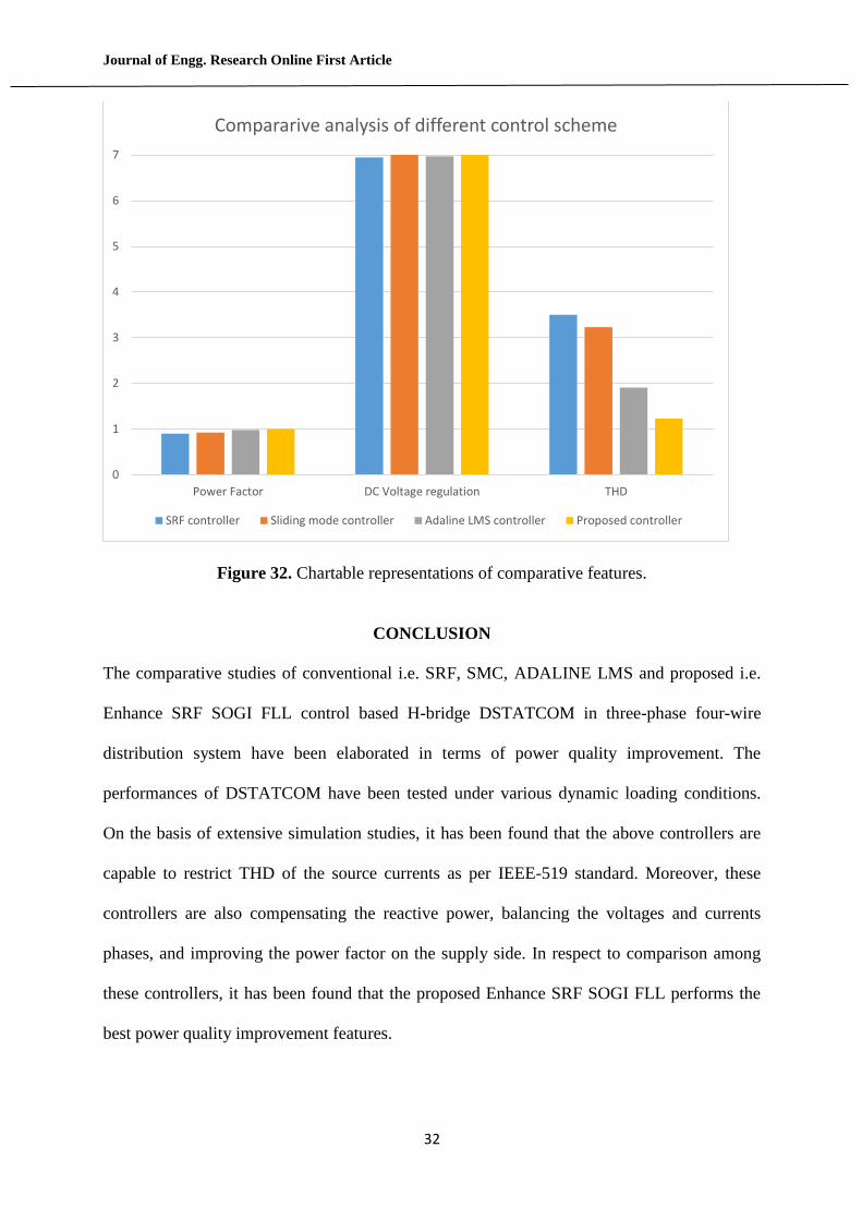
Figure 32 shows the comparative power quality features of different control algorithms in
chartable forms. To visualize the performances of power factor and THD, maximum value of
DC voltage regulation has been taken as 7 instead of 700V. In this figure, the proposed
controller represents better power quality performances.
Journal of Engg. Research Online First Article
31
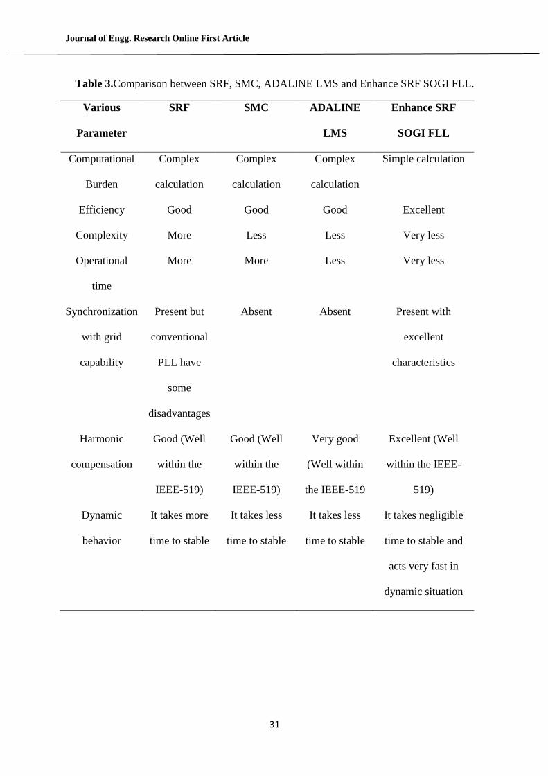
Table 3.Comparison between SRF, SMC, ADALINE LMS and Enhance SRF SOGI FLL.
Various
Parameter
SRF SMC ADALINE
LMS
Enhance SRF
SOGI FLL
Computational
Burden
Complex
calculation
Complex
calculation
Complex
calculation
Simple calculation
Efficiency Good Good Good Excellent
Complexity More Less Less Very less
Operational
time
More More Less Very less
Synchronization
with grid
capability
Present but
conventional
PLL have
some
disadvantages
Absent Absent Present with
excellent
characteristics
Harmonic
compensation
Good (Well
within the
IEEE-519)
Good (Well
within the
IEEE-519)
Very good
(Well within
the IEEE-519
Excellent (Well
within the IEEE-
519)
Dynamic
behavior
It takes more
time to stable
It takes less
time to stable
It takes less
time to stable
It takes negligible
time to stable and
acts very fast in
dynamic situation
Journal of Engg. Research Online First Article
32
Figure 32. Chartable representations of comparative features.
CONCLUSION
The comparative studies of conventional i.e. SRF, SMC, ADALINE LMS and proposed i.e.
Enhance SRF SOGI FLL control based H-bridge DSTATCOM in three-phase four-wire
distribution system have been elaborated in terms of power quality improvement. The
performances of DSTATCOM have been tested under various dynamic loading conditions.
On the basis of extensive simulation studies, it has been found that the above controllers are
capable to restrict THD of the source currents as per IEEE-519 standard. Moreover, these
controllers are also compensating the reactive power, balancing the voltages and currents
phases, and improving the power factor on the supply side. In respect to comparison among
these controllers, it has been found that the proposed Enhance SRF SOGI FLL performs the
best power quality improvement features.
0
1
2
3
4
5
6
7
Power Factor DC Voltage regulation THD
Compararive analysis of different control scheme
SRF controller Sliding mode controller Adaline LMS controller Proposed controller
Journal of Engg. Research Online First Article
33
REFERENCES
Arya, S.R., Patel, M.M., Alam, Z.S., Sri, J., & Giri, A.K. 2020. Phase lock loop- based
algorithm for DSTATCOM to mitigate load created power quality problems. International
Transaction of Electrical Energy Systems 30(1):1-26.
Arya, S.R., Singh, B., Niwas, R., Chandra, A., & AL-Haddad, K. 2016. Power quality
enhancement using DSTATCOM in distribution power generation system. IEEE
Transaction on Industry Application 52(6):5203-5212.
Bhattacharya, A. & Chakraborty, C. 2011. A shunt active power filter with enhanced
performance using ANN-based predictive and adaptive controllers. IEEE Transaction on
Industrial Electronics 58(2):421–428.
Cespedes, M. & Sun, J. 2014. Impedance modelling and analysis of grid- connected voltage-
source converters. IEEE Transaction on Power Electronics 29(3):1254-1261.
Chauhan, S. K., Shah, M.C., Tiwari, R.R., & Tekwani, P.N. 2014. Analysis, design and
digital implementation of shunt active filter with different schemes of reference current
generation. IET Power Electronics 7(3):627-639.
Chittora, P., Singh, A., & Singh, M. 2018. Simple and efficient control of DSTATCOM in
three phase four wire polluted grid system using MCCF-SOGI based controller. IET
Generation Transmission Distribution 12 (5):1213-1222.
Golestan, S., Guerrero, J.M, Vasquez, J.C., Abusorra, A. M. & Al-Turki, Y. 2018.
Modeling, tuning, and performance comparison of advanced second-order generalized
integrator-based FLLs. IEEE Transaction on Power Electronics 33(12):10229-10239.
Hao, Yi., Wang, X., Blaabjerg ,F. & Zhuo, F. 2017. Impedance analysis of SOGI-FLL-
based grid synchronization. IEEE Transaction on Power Electronics 32(10):7409-7413.
Journal of Engg. Research Online First Article
34
IEEE Std. 519. 2014. Recommended Practice and Requirements for Harmonic Control in
Electric Power Systems. IEEE: 1-17.
Kumar, P., Kumar, N., & Akella, A.K. 2014. A simulation based case study for control of
DSTATCOM. ISA Transactions 53(3): 767-775.
Patnaik, S.S. & Panda, K.A.2013. Three level H-bridge and three H-bridges-based three
phase shunt active power filter topologies for high voltage applications. International
journal of Electrical Power and Energy systems 51(10):298-306.
Qasim, M., Kanjiya, P., & Khadkikar, V. 2014. Optimal current harmonic extractor based
on unified ADALINEs for shunt active power filters. IEEE Transaction on Power
Electronics 29(12):6383-6393.
Sekhar, V.C., Kant, K., & Singh, B. 2016. DSTATCOM supported induction generator for
improving power quality. IET Renewable Power Generation 10(4):495-503.
Singh, B., Chandra, A., & Al-Haddad, K. 2015. Power quality: problems and mitigation
techniques. Wiley, U. K.
Singh, B., Jaiprakash, P., & Kothari, D.P. 2011. New control approach for capacitor
supported DSTATCOM in three-phase four wire distribution system under non-ideal
supply voltage conditions based on synchronous reference frame theory. International
journal of Electrical Power and Energy Systems 33(5):1109-1117.
Srinivas, B., Geddada, N., Mishra, M. K., & Kumar, B.K. 2011. A DSTATCOM topology
with reduced DC-link voltage rating for load compensation with non-stiff source. IEEE
Trans. Power Electron 27(3):1201-1211.
Srinivas, V. L., Kumar, S., Singh, B., & Mishra, S. 2017. Partially decoupled adaptive filter
based multifunctional three-phase GPV system. IEEE Transaction on Sustainable Energy
9(1):311-320.

Journal of Engg. Research Online First Article
35
Wen, B., Dong, D., Boroyevich, D., Burgos, R., Mattavelli P., & Shen, Z. 2016. Impedance-
based analysis of grid-synchronization stability for three-phase paralleled converters.
IEEE Transaction on Power Electronics 31(1):26-38.
Zainuri, M. A. A. M., Radzi, M. A. M., Soh, A. C., Mariun, N., & Rahim, N. A. 2016.
DC-link capacitor voltage control for single-phase shunt active power filter with step size
error cancellation in self-charging algorithm. IET Power Electronics 9(2): 323-335.
Zaveri, T., Bhalja, B., & Zaveri, N. 2012. Comparison of control strategies for
DSTATCOM in three-phase, four-wire distribution system for power quality improvement
under various source voltage and load conditions. International journal of Electrical Power
and Energy systems 43(1):582-594.