comparative seakeeping performance analysis of a … · in this paper, some seakeeping analyses...
TRANSCRIPT
Accepted author manuscript of the following research output: Tezdogan, T., & Aldogan, A. I. (2011). Comparative seakeeping performance analysis of a warship. 317-
324. Paper presented at 1st International Symposium on Naval Architecture and Maritime, Istanbul, Turkey.
Comparative Seakeeping Performance Analysis of a Warship
Tahsin Tezdogan
Research Assistant, Istanbul Technical University, Turkey, [email protected]
Ali Ihsan Aldogan
Prof. Dr., Istanbul Technical University, Turkey
Abstract
A successfully designed ship is expected to fulfill her mission in almost all weather and sea states without
compromising her safety. This is particularly important for a warship and crew onboard to be able to perform
their complex tasks in good physical and mental state.
This paper presents comparative seakeeping performance analysis of a warship operating in Turkish waters,
which include Mediterranean Sea, Aegean Sea and Black Sea, for varying sea states, wave headings and
ship speeds.
The comparative analysis was conducted by using a commercial seakeeping package (ShipmoPC), which is
a strip theory based software, for the 6 degrees of freedom motion responses as well as the vertical
accelerations, and added wave resistance. The effect of active fins on the roll motion responses was also
explored. The analysis results were compared with the NATO Standardization Agreement (STANAG 4154)
criteria. The results were presented in standard graphical format and polar diagrams, and discussed in details
in the paper.
Keywords Seakeeping, Strip Theory, Ship Motions, Warships
1. Introduction
The overall performance of a ship depends on the seakeeping performance in specified sea areas where the
vessel operates. She is supposed to perform her duties even in severe sea conditions. Therefore, prediction
of ship motions and seakeeping performance are very important for a ship in the preliminary design stage.

In this paper, some seakeeping analyses were conducted for a warship operating in Turkish waters for
varying sea states, wave headings and ship speeds. The results of analysis were presented in graphical
format.
The factors which lead to restrict performance of a warship in a seaway may be listed as follows:
Severe ship motions due to waves
Motion induced interruptions
High accelerations
Slamming
Deck wetness
Propeller emergence
In order to assess of seakeeping performance of a warship in a specified sea environment, these inputs must
be identified completely:
Type of a warship and her missions
Principal dimensions and hull geometry
Mass distribution
Coordinates of critical points for the vessel such as helipad, bridge deck, combat operations center
Sea areas where the ship operates and sea states
Seakeeping criteria which is determined in accordance with her type, her mission, and her armament
After the determination of foregoing inputs, seakeeping analysis of a warship was carried out by the aid of
a commercial seakeeping package, ShipmoPC, which is a 2-D strip theory based software (BMT, 2001).
These calculations include ship responses in regular and irregular seas, added resistance due to waves, and
vertical acceleration. In addition, the effect of active fins on the roll motion responses was also explored.
1.1. Basic properties of the sample warship
The sample warship studied in this paper is a landing ship, which is a form of amphibious warship designed
to support amphibious operations. These amphibious assault ships transport and launch amphibious craft
and vehicles with their crews and embarked personnel (Web 1).
Principal dimensions of the vessel are given in table 1. Ship geometry is divided into 20 stations and 0.
station is regarded as aft perpendicular. At the same time, mass properties related to these stations are entered
into the software. Besides, bilge keel, skeg, rudder, shaft brackets and active roll fins are modeled in the
software.
Table 1. Principal dimensions of the warship

BPL 208 meters
yyk 52 meters
T 7 meters
25430 ton
BC 0.54
2. Ship Responses in Regular Seas
Ship responses in regular seas are calculated in order to obtain ship responses in irregular seas using the
linear superposition principle.
Ship motions in regular seas can be predicted experimentally, but this may not be appropriate in preliminary
design stage because data of the ship may be changed frequently. Therefore, it is really expensive and
laborious to conduct experiments for every changing situation.
It may be noted that warships with slender geometry are very suitable for 2-D linear strip theory application.
ShipmoPC provides motion predictions using a frequency domain strip theory of Salvesen et al. (1970). For
lateral plane motions, appendage and viscous forces are highly important, so their effects are computed
using Schmitke’s method (1978).
In ShipmoPC, two dimensional sectional hydrodynamic coefficients are determined using either Lewis form
method (1929) or boundary element method (Sclavounos and Lee, 1985). In this paper, the boundary
element method is chosen to compute sectional hydrodynamic properties.
Heave and pitch responses of the warship for varying headings are presented in figure 1 and 2. In these
graphics, wave frequency is given in the apsis (rad/sec), whereas the ordinate represents response amplitude
operator (RAO). These values are computed for 22 knot ship speed.
Linear motion amplitudes are non-dimensionalised by dividing by the wave amplitude (ζa) for translation
motions (surge, sway, heave), and by dividing by the wave slope amplitude (kζa) for angular motions (roll,
pitch, yaw).

Fig. 1. Heave RAO for 22 knots in regular waves
Fig. 2. Pitch RAO for 22 knots in regular waves
As seen in fig. 1 and 2, heave amplitudes reach maximum values in beam seas; on the other hand the highest
pitch amplitudes are occurred in head waves.

2.1. Added wave resistance in regular waves
The resistance of a ship in a seaway is known to be greater than the ship resistance in calm water. The
difference between these two values is called the added resistance. Added resistance due to the waves is
predicted not only experimentally but also analytically from the ship motions using the strip theory. The
added resistance prediction in ShipmoPC is executed using the near-field method given by Faltinsen et al.
(1980).
The added wave resistance of the warship for varying speeds is shown in figure 3. Horizontal axis of the
graphic is non-dimensional encounter frequency coefficient, and the vertical axis is non-dimensional added
resistance coefficient. These coefficients are derived as given in equation 1 and 2:
Non-dimensional encounter frequency coefficient: μe=ωe√(L/g) (1)
Non-dimensional added resistance coefficient: 2 2( / )
AWAW
a
R
g B L
(2)
The maximum added resistance is to be expected in head waves, so the added resistance prediction in figure
3 is computed for regular head waves. It is obvious from figure 3 that added resistance increases with
increasing ship speed.
Fig. 3. Added resistance curves of the warship for varying ship speeds in regular head waves

3. Definition of the Seaway
The regular waves are seldom found in nature and hence the RAOs are of little consequence on their own.
The natural seaway in which a ship operates can only be described by means of a statistical model. The
spectrum or spectral density function is the primary device used for representing the seaway and the
oscillatory response of the vessel to the seaway. The wave characteristics of an area must be known in terms
of the distribution of wave energy with respect to frequency and direction, as well as the severity of seas as
indicated by the wave height probability distributions. The wave energy distribution within various wave
height bands can be represented through the use of a wave spectral family, Sarioz and Narli (2005).
The most used mathematical sea spectrum model is two-parameter ITTC spectrum (ITTC, 1978).
5 4exp
A BS
(3)
where A and B constants are defined by
2
1/3
1
173H
AT
and
4
1
691B
T (4)
where T1 is mean wave period and modal wave period equals Tm=1.2958T1.
In this paper, two-parameter ITTC spectrum is used to model Turkish waters including Mediterranean Sea,
Aegean Sea and Black Sea. Significant wave heights and modal wave periods to represent Turkish waters
are given in table 2.
Table 2. Significant wave heights and modal periods for varying sea states for Turkish waters (Tezdogan, 2011)
SEA
STATE
SIGNIFICANT
WAVE HEIGHT
(m)
MODAL WAVE PERIOD (sec)
BLACK SEA MEDITERRANEAN AEGEAN SEA
1 0.05 3.53 4.42 3.63
2 0.3 4.14 5 4.01
3 0.88 5.41 6.25 4.86
4 1.88 7.28 8.15 6.25
5 3.25 9.1 10.16 7.96
6 5 10.19 11.74 9.81
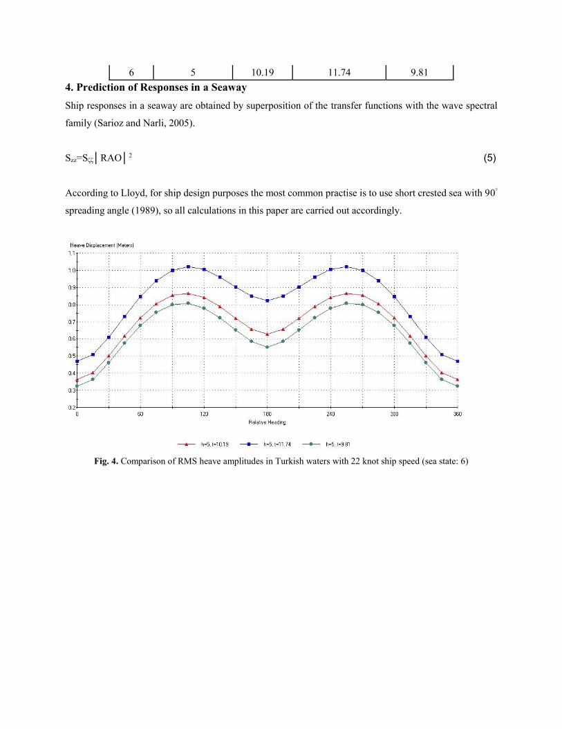
4. Prediction of Responses in a Seaway
Ship responses in a seaway are obtained by superposition of the transfer functions with the wave spectral
family (Sarioz and Narli, 2005).
Szz=Sζζ│RAO│2 (5)
According to Lloyd, for ship design purposes the most common practise is to use short crested sea with 90°
spreading angle (1989), so all calculations in this paper are carried out accordingly.
Fig. 4. Comparison of RMS heave amplitudes in Turkish waters with 22 knot ship speed (sea state: 6)

Fig. 5. Comparison of RMS pitch amplitudes in Turkish waters with 22 knot ship speed (sea state: 6)
RMS heave and pitch displacements in irregular seas are shown in figure 4 and 5, respectively. In these
calculations, significant wave height and modal period values are chosen at sea state 6 given in table 2.
According to these graphics, blue curves represent Mediterranean Sea, red curves represent Black Sea, and
green ones present Aegean Sea. As shown in figure 4 and 5, heave and pitch amplitudes reach maximum
values in Mediterranean among the other seas.
4.1. Rolling analysis
Rolling has a remarkable importance on human comfort and safety of the cargo. Hence, it should be
predicted with enough accuracy. Despite the great impact of rolling on ship operations, it is the most difficult
motion to predict because of the viscous effects. According to McTaggart, ShipmoPC uses the Schmitke’s
method to include viscous effects in lateral motions (1997).
The polar diagram showing RMS roll amplitudes of the warship for different ship speeds in Mediterranean
(sea state: 6) is given in figure 6. It can be said that the most severe roll amplitude is predicted for zero speed
in beam seas (approx. 4°). Roll motion is decreasing with the increasing ship speed between 0-22 knots
speed interval.

Fig. 6. Polar diagram shows RMS roll amplitudes for different ship speeds (Mediterranean, sea state: 6)
4.2. Effect of the active roll stabiliser fin on roll motion
Active roll stabiliser fins are usually mounted on rotatable stocks at the turn of the bilge near the middle of
the ship. The angle of incidence of the fins is continually adjusted by a control system which is sensitive to
the rolling motion of the ship. The fins develop lift forces which exert roll moments about the centre of
gravity of the ships. There roll moments are arranged to oppose the moment applied by the waves and the
roll motion is reduced, Lloyd (1989).
The warship has active roll fin besides bilge keel. Some properties of the active fin are given in table 3.
In this part, performance of the active roll fin is assessed. For this purpose, rms roll amplitudes are calculated
considering the effect of roll fin firstly, and then the same analysis is carried out without roll fin in the same
sea conditions. Analysis of roll motion is performed in Mediterranean (sea state: 6) for 22 knots ship speed.
In all circumstances, the contribution of the bilge keel to roll motion is included to the calculations. The
comparative graphic is shown in figure 7.

Table 3. Properties of the active roll fin (Tezdogan, 2011)
Properties Values
Roll acceleration gain 4.13 sec2
Roll velocity gain 4.07 sec
Control system natural frequency 0.492 rad/sec
Control system damping ratio 0.076
Fig. 7. The effect of active roll fin on roll amplitudes for 22 knots ship speed (Mediterranean, sea state: 6)
It is stated that the active roll fin reduces maximum roll amplitudes by approx. 44% according to figure 7.
The vessel should purpose to minimize roll amplitudes to carry on her tasks safely.
4.3. Vertical acceleration analysis
The amplitude of vertical acceleration ( )az&& at any point along the ship length is given by (Bhattacharyya,
1978):
2 2 2 2( ) ( ) ( ) 2( ) ( ) cosa a b a a a bz z x z x &&&& && && (6)
0.0
0.5
1.0
1.5
2.0
2.5
0 30 60 90 120 150 180 210 240 270 300 330 360
RM
S R
oll
Am
pli
tud
e (d
er)
Heading
with roll fin
without roll fin

where ( )az&& is the amplitude of heaving acceleration at the CG, and ( )a&& is the amplitude of pitching
acceleration at the CG. is the phase angle.
Figure 8 shows the effect of changing severity of the sea on vertical acceleration. The calculations are done
in head seas for different vessel speeds.
Fig. 8. Effect of severity of the sea on vertical acceleration for varying ship speeds in head seas (Black Sea)
The analyses are conducted at a point on the bridge deck. The ordinate of the figure 8 is given as significant
vertical acceleration, whereas the x-axis represents varying sea states. As seen in figure 8, the significant
vertical acceleration values are increasing as the severity of the sea goes up. As expected, vertical
acceleration increases with ascending ship speed.
Figure 9 illustrates the effect of changing longitudinal location on vertical acceleration in sea state 6 in
Mediterranean at 16 and 22 knots. The calculations are done on the centerline of the warship at the same
height as the vertical center of gravity (VCG). It may be noted that there is a strong dependence on
longitudinal location, and RMS vertical acceleration is 3.75 times greater at forward perpendicular than at
Station 8 (at 22 knots).
0.00
0.20
0.40
0.60
0.80
1.00
1.20
3 4 5 6
Sig
nif
ican
t V
erti
cal A
cc. (m
/sn
²)
Sea State
0 knot
5 knot
10 knot
15 knot
20 knot
25 knot

Fig. 9. Effect of longitudinal location on vertical acceleration in head seas (Mediterranean, sea state: 6)
5. Seakeeping Criteria
Sarioz and Narli point out that “in order to assess the effect of seakeeping performance on the mission
capability of the vessel the mission requirements need to be translated into seakeeping performance
requirements” (Sarioz and Narli, 2005).
Criterions for seakeeping performance are different for all vessels with respect to their types, missions and
armament. Also, most of criterions can vary depending on the location and region. Every mission has its
own special limit value that makes seakeeping criteria a complex issue.
Some limit values for a warship which has transit and patrol missions are given in table 3. These values may
be appropriate for the warship discussed in this paper.
Table 3. Seakeeping criteria: transit and patrol mission (NATO, 2000)
Parameter Limit Value
Roll angle 4.0 RMS deg
Pitch angle 1.5 RMS deg
Vertical acceleration 0.2 RMS g
Deck wetness index 30 per hour
Bottom slamming index 20 per hour
Helicopter take off (roll) 3.0 RMS deg
Helicopter take off (pitch) 1.0 RMS deg

Conclusions
Examining analyses results, it is appeared that the highest values of ship motions, added resistance, and
vertical acceleration are occurred in Mediterranean Sea, and then it is followed by Black Sea and Aegean
Sea.
The motions in regular seas are computed in order to calculate ship responses in irregular seaways using the
linear superposition principle. The challenging part of predicting ship responses in irregular seas is to model
real sea waves adequately. To do this, some mathematical sea spectrums are derived and consequently they
simplify the calculations.
In this paper, two-parameter ITTC spectrum has been used to model Turkish waters. All the analyses have
been done according to this.
The effect of active roll fin has been evaluated and it may be noted that it reduces maximum roll amplitudes
by approx. 44%.
In the next part, vertical accelerations have been computed and the effect of longitudinal position on vertical
acceleration has been assessed. It may be concluded that the influence of longitudinal location is very
significant and RMS vertical acceleration is 3.75 times greater at forward perpendicular than at Station 8.
Finally, seakeeping criteria is explained briefly. Seakeeping performance of a warship enormously depends
on the chosen limit values. Sample seakeeping criterions taken from STANAG 4154 have been given in the
paper.
Acknowledgements
This paper has been dedicated in the memory of Prof. Dr. Ali Ihsan ALDOĞAN, who passed away on 11th
of February, 2011.
I wish to thank Prof. Dr. Mehmet ATLAR who gave me his support at Newcastle University. I am really
grateful to him for his assistance. I would like to also thank my thesis advisor, Prof. Dr. Metin TAYLAN,
who shared all his experience and knowledge with me.
References
Bhattacharyya, R., (1978). Dynamics of Marine Vehicles. McCormick, M. E. (Ed.), Wiley, New York.
British Maritime Technology (BMT), (2001). ShipmoPC Version 3 User Manual. Revision 10, BMT Fleet
Technology Limited, Canada, pp. 107.
Faltinsen, O. M., Minsaas, K. J., Liapis, N. and Skjordal, S. O., (1980). Prediction of resistance and propulsion of
a ship in seaway. 13th Symposium on Naval Hydrodynamics, Tokyo, 505-529.
ITTC Seakeeping Committee Report, (1978). 15th International Towing Tank Conference, The Hague, 1, 55-114.
Lewis, F. M., (1929). The inertia of water surrounding a vibrating ship. Transactions of SNAME 37, 1-20.

Lloyd, A. R. J. M., (1989). Seakeeping: Ship Behaviour in Rough Weather. Ellis Horwood, Chichester, United
Kingdom.
McTaggart, K. A., (1997). Shipmo7: An Updated Strip Theory Program for Predicting Ship Motions and Sea Loads
in Waves. Defence Research Establishment Atlantic, Technical Memorandum 96/243.
NATO, (2000). Common Procedures for Seakeeping in the Ship Design Process. Standardization Agreement
(STANAG 4154).
Salvesen N., Tuck E. O. and Faltinsen O., (1970). Ship motions and sea loads. Transactions of SNAME 78, 250-
287.
Sarioz, K. and Narli, E., (2005). Effect of criteria on seakeeping performance assessment. Ocean Engineering 32,
1161-1173.
Schmitke, R. T., (1978). Ship sway, roll, and yaw motions in oblique seas. Transactions of SNAME 86, 26-46.
Sclavounos, P. D. and Lee, C., (1985). Topics on boundary element solutions of wave radiation-diffraction problems.
4th International Conference on Numerical Ship Hydrodynamics, Washington.
Tezdogan, T., (2011). Investigation of ship motions and application to ships (in Turkish) (master thesis). Thesis
advisor: Prof. Dr. Metin TAYLAN, Istanbul Technical University Graduate School of Science Engineering and
Technology.
Web 1, http://en.wikipedia.org/wiki/Dock_landing_ship