comparison between msw ash and rdf ash from …the extracted metals from the fly ash in the rdf...
TRANSCRIPT

Comparison between MSW Ash and RDF Ash
from Incineration Process
Ni-Bin Chan.g,.* ,H. P. Wang* , w. L. Huang** , K s. Lin*** and Y. H. Chang***
presented to
Fifth North American Waste-to-Energy Conference
Research Triangle Park, NC
April 21-25, 1997
* Associate Professor, Department of Environmental Engineering, National ChengKung Unicversity, Tainan, Taiwan, R.O.C.
* * Associate Professor and Chairman, Department of Ci viI Engineering, National Kaohsiung Institute of Science and Technology, Kaohsiung, Taiwan, R.O.C.
* * * Graduate Student, Department of Environmental Engineering, National ChengKung Unicversity, Tainan, Taiwan, R.O.C.
959

Comparison between MSW Ash and RDF Ash
from Incineration Process
Ni-Bin Chang, H. P. Wang, w. L Huang, K. S. Lin and Y. H. Chang
Department of Environmental Engineering National Cheng-Kung University
Tainan, Taiwan, Republic of China
ABSTRACT
Resource recovery plants with waste sorting process prior to incineration have not been successfully developed in many developing countries. The reuse potential of incineration ash in light of toxicity and compressive strength remains unclear due to the inhomogeneous composition and higher moisture content of solid waste in Taiwan. A comparative evaluation of the ash generated from two types of incineration processes were performed in this paper. The results indicate that fly ash collected from both types of incineration processes are classified as hazardous materials because of higher metal contents. The reuse of bottom ash collected from refuse-derived fuel incineration process as fine aggregate in concrete mixing would present 23% lower compressive strength as compared with the normal condition.
INTRODUCTION
In the midst of fast paced economic activities in Taiwan, the society demands
and consumes a lot of natural resources and raw materials in the creation of
products to enrich people's life. To cope with large amount of solid waste disposal
with the landfill space at a preminm in this tiny island, over thirty municipal
incinerators were planned to be built in the major metropolitan areas within the
next decade. It is estimated that there will have over two millions tonnes of
incineration ash generated every year after the year 2000 which would still
accelerate the depletion of limited landfill space. However, continuous population
growth requires more housing projects which inevitably request more production
of river sand as part of the materials in concrete mixing. This further poses
problems of erosion in light of the natural balance in the river eco-system. In
recent years, several communities in Taiwan encounter an issue that the house
they live were built using sea sand as surrogate raw materials in concrete
mixing. The fast deterioration of those building would also create a hazard to the
residents living in those communities. The term "sustainable development" has
PEER·REVIEW 960

special meanings as the wellbeing of a population of twenty million in Taiwan,
with the area no larger than thirty-six thousand square kilometers, must be
sustained probably by the reuse of incineration ash as part of the raw materials in
the future construction programs. This study tries to achieve part of the life cycle
analysis of comsumer products as they are destined for final disposal in the
municipal incinerators. The evaluation of reuse potential of those end products
from incinerators can then be regarded as an action of resource conservation and
recycling in the entire life cycle analysis.
Although Taiwan has set a bold agenda of solid waste incineration programs
to conserve the landfill space in the last few years, the continuing thinking of an
integrated incineration system with the sorting process as a pretreatment unit to
improve the incineration efficiency and generate better quality of flue gas and ash
has never been tempered. At least two proposals for installing such a sorting
process prior to the large scale municipal incinerators, located in the City of Tai
Chung and the County of Taipei, were raised in 1996. In addition, such an
integrated incineration system was also chosen for planning several medium size
modular incinerators, that are located in the rural areas in Taiwan. But the
property and reuse potential of those RDF ash remain unclear. The incineration
ash from the MSW burning is currently being used for landfilling only in Taiwan.
Backfilling of construction sites, subbase in road construction, and to some extent,
reuse for concrete mixing have been fully carried out in several laboratory
experiments. This analysis emphasizes the comparative study of property
characterization and reuse potential of ash from MSW and RDF incineration
processes, using local waste flow as fuels in Tainan area of Taiwan.
Two major facilities, located in Tainan area of Taiwan, were used as pilot
plants in this experiment. One is a refuse-derived fuel process, and the other is a
modular incinerator. Hence, two types of incineration processes can be arranged.
One has a dedicated sorting process associated with a modular incinerator while
the other has not such a sorting plant prior to incineration. The samples of
municipal solid waste (MSW) in Tainan area of Taiwan were collected and then
the refuse-derived fuel (RDF) were generated for the subsequent incineration.
Incineration ash from the waste burning process were produced and collected
from the bottom of ash discharge and the electrostatic precipitator hopper, as
denoted by the "bottom ash" and "fly ash" respectively in this study. The
properties of incineration ash were specifically characterized and the reuse
PEER-REVIEW 961

potential of bottom ash as part of the raw materials in concrete mixing was also
examined. In the first stage analysis, the unwashed incineration ash were tested
and analyzed for TCLP (Toxicity Characteristic Leaching Procedure) metals and
chemical composition using XRD and SEMIEDS techniques. In the second stage
analysis, to further evaluate the reuse potential of bottom ash, the washed bottom
ash from both types of incineration processes were tested by seieve analysis and
compressive strenth analysis. Final suggestions were made based on the tested
properties of those incineration ash.
LITERA'IURE REVIEW
In the last decade, a number of credible research efforts were carried out in
both the European countries and United States ([1] ... [3]) and the efficiency and
effectiveness of resource recovery from solid waste associated with incineration
system has been fully discussed ([4] ... [12]). However,the impacts of solid waste
sorting on incineration remain uncertain due to the higher moisture content and
plastics in solid waste composition in Taiwan, which is not fairly representative of
most other countries.
In addition, ash properties have been fully characterized in several municipal
incinerators, such as in New York City, California, Singapore, and so on ([13]
[17]). Engineering evaluation of resource recovery for incineration ash has been
performed ([18]-[19]). Specific purposes of ash utilization were fully discussed,
such as the recovery and reuse of ash as the raw materials in concrete mixing
([20]-[23]), the reuse of ash as the subbase materials in road construction and
gentechnica1 applications ([24]-25]), and even the recovery of fly ash as zeolite [26].
FACILITY DESCRIPTION
Solid Waste Sorting System
As is illustrated in Figure 1, the solid waste sorting process consists of three
major units: shredding, air classification, and screening. The facility can
process 30 tons/hr at maximum capacity per one line. The MSW is delivered to
the facility by packer trucks. A bag-ripping unit, to open plastic bags, initializes
the sorting process. Ferrous metal is then extracted from the MSW stream using
magnets. Recovered ferrous metal is conveyed to a ferrous storage bin from
PEER-REVIEW 962

where it is recycled. MSW is then processed in a vertical hammermill shredder to
reduce it to a normal size. Shredded MSW is taken to an air classifier, using a
belt-type conveyor. Non-ferrous materials, such as aluminum cans and
combustibles are crushed by the vertical hammermill shredder. A manual
sorting unit or eddy current separator could be added prior to the vertical
hammermill shredder for the recovery of aluminum cans in the future. The air
classifier, blowing with a regular air stream of 200 m3/min from the vertical
hammermill shredder, is intended to separate the inert materials, such as glass,
ceramics, and so on, to reduce the content of heavy non-combustible material in
he residual MSW streams. Light materials, passing through the air classifier,
are sent into the trommel screen for advanced separation. The dimensions of the
openings on the surface of trommel screen can be varied to fine-tune the
processing function and assure maximum combustibles recovery. The trommel
is designed with two concentric shells. The outer shell, with 2.33 meters in
diameter and 4.3 meters in length, has many circular holes on the surface which
is designed to remove the shredded materials smaller than 25 mm. The inner
shell, with 1.9 meters in diameter and 4.56 meters in length, separates partial
waste stream with the size between 25 and 100 mm. Three waste streams can be
trommeled. In other words, particle size is controlled by the openings design on
the surface of the trommel such that the material with the particle size less than
25 mm (trommel underflow) and the particle size between 25 mm and 100 mm
(trommel middle flow) are separately arranged by two different sets of openings
with a concentric shell configuration. The overflow, passing through this
trommel screen, presents the most light portion in the MSW with the size greater
than 100 mm (trommel overflow) , and can be identified as fluff-RDF. However,
both outputs with particle size larger than 100 mm and between 25 mm and 100
mm can be used as fuels in the incineration facilities.
Solid Waste Incineration System
Figure 2 presents the system configuration of the modular incinerator. The
100 Kg/hour modular incinerator was designed is equiped with an electrostatic
precipitator and a wet scrubber. From the silo the RDF or MSW is fed into the
furnace where the combustion takes place on a 3-step movable grate system. The
flue gases generated pass through the first furnace and is cooled down at the
outlet of secondary furnace. The heat exchanger is installed at the outlet of
secondary furnace for the preheating of auxiliary air. The flue gases are
PEER-REVIEW 963

eventually led through air pollution control system, consisting of a conventional
electrostatic precipitator (EP) followed by a wet scrubber. Reheat is provided to
prevent visible flue gas emissions due to higher moisture content.
TCLP ANALYSIS
Samples of fly ash and bottom ash were analyzed in accordance with the TCLP
requirements. Tables 1 and 2 list the analytical results of TCLP tests for both
bottom ash and fly ash. Two replicates were prepared to meet the QAlQC
requirements that generate the data ranges in both Tables 1 and 2. The
leachability of regulated heavy metals is affected by waste composition, its
combustion history, and handling method. This would differentiate the
fundamental difference of ash from burning MSW and RDF.
The extracted metals from the fly ash in the RDF incineration process
generally exhibit relatively lower concentrations. However, testing fly ash
revealed that both types of fly ash generated from burning MSW and RDF can be
classified as hazardous materials due to higher heavy metal content. But the
extracted metals from the bottom ash of MSW and RDF burning exhibit relatively
lower concentrations. The reason for the higher Zinc concentration leached from
RDF bottom ash is still unclear. This is probably due to the higher percentages of
paper content with printing ink in the RDF that is not Zinc-free products. Table 2
shows that extractable cadmium concentrations in both types of fly ash are far
beyond the regulatory levels. This substantial differences would make the fly ash
subject to post-treatment requirements, such as stabilization, solidification,
vitrification, and even melting processes.
CHEMICAL COMPOSITION ANALYSIS
In order to have more comprehensive insight, tasks of phase identification of
both fly ash and bottom ash by X-ray diffraction and SEMIEDS techniques have
been performed in this analysis. Table 3 lists the chemical compositions of those fly ash and bottom ash. On the average, the ash mainly comprise of Si02, CaO,
Al20g, Fe20g, Zno, MgO, and Cr20g. It appears that Fe20g constitutes the major
part of fly ash. Besides, CaO is the highest content and Si02 is the second largest
group in those bottom ash.
PEER-REVIEW 964

EVALUATION OF REUSE POTENTIAL AS FINE AGGREGATE
Sieve Analysis of Bottom Ash
Wider particle distribution exists in the bottom ash of MSW. The shape of the
particles of MSW ash is relatively irregular and flaky. Higher amount of
aluminum c�ns, metal tubes, iron wires and other ferrous metals exist in the
MSW bottom ash that makes the recovery, recycle and reuse processes become
much more difficult. After removing those impurities, Figure 3 illustrates the
grading of the MSW and RDF bottom ash. Due to the poor setting of concrete were
reported when "raw" incineration residues are used, washing process was
therefore employed to remove part of light and fine materials before the samples
were used in concrete mixing [21]. The results of sieve analysis of "unwashed"
and "washed" ash samples were both listed in Tables 4 and 5. It shows that the
particle size distributions of MSW and RDF bottom ash present similar patterns.
But relatively higher percentage of light and fine materials exists in MSW bottom
ash.
Compressive Strength Analysis
Table 6 lists the properties of normal sand, washed MSW and RDF ash. The
fineness modulus of the MSW and RDF particles are 3.34 and 3.59 respectively,
indicating a rather coarse grading. The specific gravity of the washed MSW and
RDF samples are 2.27 and 2.38, respectively. The water adsorption values are
2.0%, 9.0%, and 7.4% corresponding to the normal sand, MSW, and RDF ash
respectively. Although the specific gravity of washed incineration ash is similar
to natural sand, the water adsorption value is three more times higher. In
addition, the residual carbon contents in MSW and RDF bottom ash ranges from
2.63-2.66 (%) and 0.63-0.66 (%), respectively. These values indicate that MSW
bottom ash has a higher amount of unbumt materials.
Tests of compressive strength were conducted using washed bottom ash as fine
aggregate in a normal mix of 1:2:4 (cement:sand:coarse aggregate) at water
cement ratio of 0.7. Ordinary Portland cement was used as it would be in the
normal concrete preparation. The coarse aggregate is 20-mm maximum size
crushed granite. The bulk density of concrete mixes using normal sand, MSW,
and RDF ash as fine aggregate are 2,340 Kg/m3, 2,100 Kg/m3, and 2,110 Kg/m3,
PEER-REVIEW 965

respectively. The slump values of concrete mix with normal sand, MSW and RDF
ash are"
100 mm, 10 mm, and 20 mm, respectively. The initial setting time for the
concrete with MSW or RDF ash is about 3 hr as compared to 2 hr for the concrete
with normal sand. In general, concrete with incineration ash as fine aggregate
have longer setting times than the samples with normal sand. It appears that all the mixes with incineration ash have lower workability. However, the setting
times are well within the requirements of ASTM standards.
Cubic specimens ( 1 2mmx24mm) were then prepared and compressive
strength of the specimens at various ages (i.e., 3, 7, 14, and 28 days) were tested
according to ASTM Standards. Table 7 shows the ranges and averages of
compressive strength of concrete mixes. The strength of different batch with
normal sand mixes are generally higher than that of the mixes with washed
MSW or RDF bottom ash. The compressive strength ratio versus age for those
samples are depicted in Figure 4. The curve corresponding to the case using
MSW bottom. ash as fine aggregate present inconsistent trend as compared with
the other two curves. This is probably due to the inhomogeneous nature of MSW
ash samples. The average compressive strength of ash mixes are lower than that
of the normal sand mixes at all ages. For concrete mixes with water-cement ratio
of 0.7, the compressive strength of the MSW and RDF ash mixes are about 54.7%
and 35.2% lower than normal sand mixes at the final stage with the age of 28
days, respectively. The reason why concrete mixes with RDF bottom ash presents
higher compressive strength as compared with MSW bottom ash is mainly due to
the existing of more uniformly distributed particle size in the RDF bottom ash.
However, the design strength of normal concrete mixes is 210 Kg/cm2 in Taiwan.
This implies that compressive strength of concrete mixes with the washed RDF
bottom ash as fine aggregate presents about 23% lower than the designed
compressive strength of concrete mixes with normal sand. Such outcomes would
limit the reuse potential of RDF bottom ash in some construction programs.
CONCLUSIONS
In recent years, the public is concerned about the changing characteristics of
incineration in response to the increase of heating values, incinerator emissions
and ash properties. This paper specifically investigates the asli property and
reuse potential from burning two types of wastes (MSW and RDF) as fuels. The
TCLP tests reveal that the bottom ash generated from burning MSW and RDF can
PEER-REVIEW 966

be classified as non-hazardous materials. But both types of fly ash require posttreatment due to higher content of heavy metals. To evaluate the reuse potential of those bottom ash, compressive strength tests were also conducted using washed bottom ash as fine aggregate in a normal mix at general water-cement ratio conditions. These data are useful in determining which applications may be better suited for different sources of ash. Final suggestions of reuse potential of bottom ash as .. fine aggregate in concrete mixing can be made based on the tested properties of compressive strength and workability. Test results indicate that mass burn of MSW may result in a lower ash reuse potential due to inhomogeneous mixes. Overall, the inclusion of waste sorting process prior to the incineration facilities can provide RDF with better quality to the mass burn process and higher reuse potential of RDF bottom ash may be attained. However, due to relatively lower compressive strength as compared with normal concrete mixing, the reuse potential of incineration ash is rather limited in some construction programs.
Acknowledgement
The authors acknowledge the financial support from the National Science Council (NSC-85-2621-P-006-033) and helpful comments of anonymous referees in the review process.
l.Sommer, E. J., Kenny, G. R., and Roos, C. E., "Mass Burn Incineration with a Presorted MSW Fuel," Journal of Air & Waste Management Association, Vol. 39(4): 511-516 (1989).
2.Jackson, D. V., "Advances in Thermal Treatment and RDF," Resources and Conservation, 14:1-13 (1987).
3.Bunsow, W. and Dobberstein, J., "Refuse-derived Fuel: Composition and Emissions from Combustion," Resources and Conservation, 14:249-256 (1987).
4.Wilson, D. C., "The Efficiency of Resource Recovery from Solid Waste," Resource Recovery and Conservation, 4:161-188 (1979).
5.Eastman, R. M., "Quality Control in Resource Recovery," Re source Recovery and Conservation, 4:189-201 (1979).
6.Eley, M. H. and Guinn, G. R., "A New Processing System for the Production of Improved Refuse Derived Fuel and Recyclables from Municipal Solid Waste," in Proceedings of 1994 National Waste Processing Conference, 1994, Boston, Massachusetts, USA, 283-291.
7.Ferraro, F. A., "Results of Emissions and Ash Testing at a Modern Refusederived Fuel Plant," in Proceedings of Resource Recovery of Municipal Solid Waste, Knox, P. J., editor, AIChE Symposium Series, 1988, pp. 36-42.
8.Jackson, D. V.,"Advances in Thermal Treatment and RDF," Resources and Conservation, 14:1-14 (1987).
PEER-REVIEW 967
9.Kreiter, B. G., "The Effectiveness of Waste Treatment Systems," Resource Recovery and Conservation, 4: 203-207 (1979).
10.Sokol, D. L., "Refuse-derived Fuel Versus Mass-burn Technology: Ogden Martin's HaverhilllLawrence, Massachusetts Projects," in Proceedine-s of Resource Recoyery of Municipal Solid Waste, 1988, Knox, P. J., editor, AIGhE
Symposium Series, 30-35. I1.Sommer, E. J. Jr., Kenny, G. R., Kearley, J. A., and Roos, C. E.,"Mass Burn
Incineration with Presorted MSW Fuel," Control Technoloa, 39 (4):24-30 (1989).
12.Wilson, D. C., "The Efficiency of Resource Recovery from Solid Waste," Resource Recoyery and Conservation, 4:161-188 (1979).
13.Tay, J. H. and Goh, A. T. C.,"Engineering Properties of Incinerator Residue," Journal of Enyironmental Engineering, ASCE, 117 (2):224-235, (1991).
14.Poran, C. J. and Faouzi, A. A.,"Properties of Solid Waste Incinerator Fly Ash," Journal of Geotchnical Ene-ineerine-, 115 (8):1118-1132, 1989.
15.Levie, B., Sevy, D., Tormey, M. and Boughton, B.,"Ash Characterization of California MSW Incinerators," in Proceedine-s of 1994 National Waste Processing Conference, 1994, Boston, Mass., USA, 99-106.
16.Chesner, W. H., Collins, R. J., and Fiesinger, T.,"The Characterization of Incinerator Residue in the City of New York," in Proceedings of 1986 National Waste Processine- Conference, 1986,419-434, Denver, Colorado, USA.
17.Savage, G. M. and Diaz, L. F.,"Characteristics of RDF Ash," in Proceedin@ of 1988 National Waste Processine- Conference, 1988, 139-144, Philadelphia, Penn., USA.
18.Richard, W. G.,"Engineering Evaluation of Resource Recovery Residue Utilization Modes," in Proceedings of the Second Internation al Conference on Municipal Solid Waste Combustor Ash Utilization, 1989, Houston, Texas, USA
363-380. 19.Black, G. A. and Cunningham, J. C.,"Ash Block as a Utilization Product,"in
Proceedings of the Fourth Internation al Conference on Municipal Solid Waste Combustor Ash Utilization, 1991, Arlington, Virginia, USA 181-190.
20.Javed, I. B. and Kenneth, J. R.,"Light Weight Aggregates from Incinerated Sludge Ash," Waste Management & Research, 7:363-376 (1989).
21.Tay J. H.,"Energy Genration and Resource Recovery from Refuse Incineration," Journal of Enera Engineering, ASCE, 114 (3):107-117 (1988)
22.Ali, M. T. and Chang, W. F.,"Strength Properties of Cement-stabilized Municipal Solid Waste Incinerator Ash Masonry Bricks," ACI Materials Journal, 91 (3):256-263 (1994).
23.Yip, W. K.,"Aggregate made from Incinerated Sludge Residue," Journal of Materials in Civil Engineering, 2 (2):84-93 (1990).
24.Aziz, M. A. and Ramaswamy, S. D.,"Incinerator Residue for Roads," Geotechnic al Testing Journal, 15 (3): 300-304 (1992).
25. Goh, A. T. C. and Tay, J. H.,"Municipal Solid Waste Incinerator Fly Ash for Geotechnical Applications," Journal of Geotechnical Engineering, 119 (5):811-
825 (1993). 26.Lin, C. F. and Hsi, H. C., "Resource Recovery of Wate Fly Ash: Synthesis of
Zeolite-like Materials," Environmental Science & Technology, 29 (4):1109-1116 (1995). ..
PEER-REVIEW 968

Table 1 : TCLP analysis of bottom ash
MSW Pb(mgIL) ND�ND<0.03
Cd(mgIL) 0.01�0.02
Cu(mg.L) 0.3�0.4
Zn(mgIL) 1.5�1.6
Cr(mgIL) 0.03�0.04
RDF 0.11�0.12
0.05�0.06
0.39�0.40
16.1�16.3
0.12�0.13
HgtmgIL) ND�ND<0.0002 ND�ND<0.0002
As(mgIL) ND�ND<O.OO 1 ND�ND<O.OOI
pH 11.8 10.2
Cr+6(mgIL) 0.005�.006 0.05�0.06
CN-�mgIL) ND�ND<0.002 ND�ND<0.002
Table 2 : TCLP analysis of fly ash
TCLP Standards 5.0
1.0
15
25
5.0
0.2
5.0
2.5
MSW RDF TCLP Standards Pb(mgIL) 9.48�9.65 0.03�.05
Cd(mgIL) 4.60�4.67 2.599�2.614
Cu(mg.L) 22.3�22.4 9.62�9.66
Zn(mgIL) 5.22�5.34 21.5�21.8
Cr(mgIL) ND�ND<0.02 0.04�0.06
Hg(mgIL) ND�ND<O.0002 ND�ND<0.0002
As (mgIL) ND�ND<O.OO 1
pH 5.6
Cr+6(mgIL) 0.002�0.004
CN�m�2 0.002�0.003
Table 3 : Chemical composition of ash
ND-ND<O.OO 1
5.0
0.002�.003
ND-ND <0.002
5.0
1.0
15
25
5.0
0.2
5.0
2.5
MSW bottom ash MSW fly ash RDF bottom ash CaO(%) 34.678 16.901 44.668
Si02(%) 18.653 12.481 19.861
Ah03(%) 13.973 5.946 13.392
Fe203(%) 27.053 48.341 10.327
ZnO(%) 13.336 5.325
MgO(%) 5.492 4.577
Cr203(%) 2.926 1.836
total(%) 99.850 99.932 99.987
PEER-REVIEW 969
RDF fly ash 19.546
20.186
10.897
43.978
3.528
1.590
0.164
99.890

Table 4: Particle size distribution ofRDF bottom ash
retained amount accumulated amount accumulated percent accumulated percent SIeve no.
by weight (g) by weight (g) retained by weight(%) passing by weight(%)
washed unwashed washed unwashed washed unwashed washed unwashed
#4 50 50 50 50 5.38 5.03 94.62 94.97
#8 96 96 146 146 15.70 14.69 84.30 85.31
#16 156 156 302 302 32.47 30.38 67.53 69.62
#30 178 178 480 480 51.61 48.29 48.39 51.71
#50 146 146 626 626 67.31 62.98 32.69 37.02
#100 176 176 802 802 86.24 80.68 13.76 19.32
#200 128 128 930 930 100.00 93.56 0.00 6.44
residual 64 994 100.00 0.00
Table 5: Particle size distribution ofMSW bottom ash
retained amount accumulated amount accumulated percent accumulated percent SIeve no.
by weight {g) by weight {g2 retained by weight{%) passing by weight{%)
washed unwashed washed unwashed washed unwashed washed unwashed
#4 56 56 56 56 6.35 5.81 93.65 94.19
#8 112 112 168 168 19.05 17.43 80.95 82.57
#16 96 96 264 264 29.93 27.39 70.07 72.61
#30 114 114 378 378 42.86 39.21 57.14 60.79
#50 104 104 482 482 54.65 50.00 45.35 50.00
#100 230 230 712 712 80.73 73.86 19.27 26.14
#200 170 170 882 882 100.00 91.49 0.00 8.51
residual 82 964 100.00 0.00
PEER-REVIEW 970
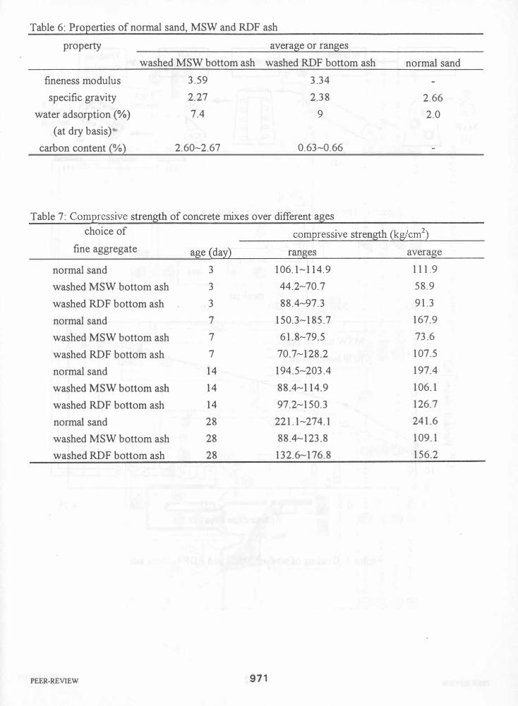
Table 6: Properties of normal sand, MSW and RDF ash
property average or ranges
washed MSW bottom ash washed RDF bottom ash normal sand
fineness modulus 3.59 3.34
specific gravity 2.27 2.38 2.66
water adsorption (%) 7.4 9 2.0
(at dry basis)
carbon content (%) 2.60�2.67 0.63�0.66
Table 7: Compressive strength of concrete mixes over different ages choice of compressive strength (kg/cm2)
fine aggregate age (day) ranges average
normal sand 3 106.1�114.9 111.9
washed MSW bottom ash 3 44.2�70.7 58.9
washed RDF bottom ash 3 88.4-97.3 91.3
normal sand 7 150.3-185.7 167.9
washed MSW bottom ash 7 61.8-79.5 73.6
washed RDF bottom ash 7 70.7-128.2 107.5
normal sand 14 194.5-203.4 197.4
washed MSW bottom ash 14 88.4-114.9 106.1
washed RDF bottom ash 14 97.2-150.3 126.7
normal sand 28 221.1-274.1 241.6
washed MSW bottom ash 28 88.4-123.8 109.1
washed RDF bottom ash 28 132.6-176.8 156.2
PEER-REVIEW 971

Bag-ripping
100
100
90
80 ,,-., � 70 '-" .S 60 rJ:l
rJ:l
a 50
� Q) 40 C,) �
30 Q) p..
20
10
0
0.15
PEER-REVIEW
---Magnetic ..... Shredding --. separation -
Air .... Trammel classifying - screening
�. . 0 0 >100mm o '--'O--'�' '-', m:��� 0 - - - - - - - � .: � '. ... 0
00 �� material
:� : . 00 ' (6) !:-' 0 : --..
Ferrous ' : . tal Heavy < 25 mm..;. 25-100 mm
(�) material material material (3) (4) (5)
Figure 1: The system configuration of solid waste sorting process
mesh no. 50 30 16 8 4
� MSW bottom ash
- - -0- - -RDF bottom ash
.......... D"
.' ,,-
.0"
.-
0.3 0.6 1.18 2.36 4.75
Aperture size (mm)
Figure 3: Grading of washed MSW and RDF bottom ash
...
972

I
CD " W
. -@-----------------------------0------------------------------------ ------ -- ------
-- ------------�-------------------�----------------------- -- -- ------------ --------�
-�
4------, . I I
o
� Gtn- : I =-H I �
---, I I I
-, I I I I I I I I I
I I
* I
I I
@
0Fe�d:h:t;-----®A�hC��v-e;�r-®.jR�;'�;;�-�JS�;'k �
.:1-'P;;�;'�- F�;"�;;T,-'; p� -f ... ·.-OU�I��T;m���fEP-(@.���u� -:as Flowrate of
® Primary Furnace ® EP @NaOH .:f-.2r econdary Furnace Temp . '. Scrubber Temp. �C:J'oling Water Flowrate ® Secondary Furnace (j) I.D.Fan Qj) Water Supply AiliAuxiliary Air Temp. MReheater Temp. �pH of Scrubber Water CD Cooling Chamber ® Wet Scrubber © Fuel Oil Tank '&Outlet Temp. of FurnacerED0verfire Air Flowrate@Exit Temp. of Stack
Figure 2: The system configuration of solid waste incineration process

1.0 ,,-... 00 0.9 (j 4::i 0.8 '--' 0
'.j:j � 0.7
"to 0.6 Q 0.5 Q) � CIl 0.4 Q) ;> .- 0.3 CIl CIl Q) '""' 0.2 S 0 0.1
U 0.0
/
0 7 14
Age (days)
___ normal sand � MSWash ___ . RDF ash
21 28
Figure 4: Compressive strength ratio versus age for different condictions of concrete mixing
PEER-REVIEW 974