comparison of phosphate scaffolds for candidate … · bone tissue engineering 1. b .2.a...
TRANSCRIPT

A COMPARISON OF 3-DIMENSIONAL CALCIUM PHOSPHATE SCAFFOLDS FOR CANDIDATE BONE TISSUE ENGINEERING
CONSTRUCTS
Dolores Ba ks h
A thesis submitted in conformity with the requirements for the degree of Master of Applied Science
Department of Chexnical Engineering and Applied Chemistry & The Institute of Biomaterial and Biomedical Engineering
University of Toronto
O Copyright by Dolores Baksh 1999

National Library Bibliit m u e nationale du Canada
Acquisitions and Acquisitions et Bi bliographic Services services bibliographiques 395 Wellington Street 395. rue Weîlington OttawaON KlAON4 OmwaON KlAûN4 canada Canada
The author has granted a non- exclusive licence allowing the National Library of Canada to reproduce, loan, distribute or sell copies of this thesis in microfoxm, paper or electronic formats.
The author retains ownership of the copyright in this thesis. Neither the thesis nor substantial extracts fkom it may be printed or othenvise reproduced without the author's permission.
L'auteur a accordé une licence non exclusive permettant à la Bibliothèque nationale du Canada de reproduire, prêter, distribuer ou vendre des copies de cette thèse sous la forme de microfiche/fÏltn., de reproduction sur papier ou sur format électronique.
L'auteur conserve la propriété du droit d'auteur qui protège cette thèse. Ni la thèse ni des extraits substantiels de celle-ci ne doivent être imprimés ou autrement reproduits sans son autorisation.

Dolores Baksh, M.A.Sc., 1999 Department of Chemical Engineering and Applied Chemistry & The Lnstitute for Biomaterials and Biomedical Engineering
University of Toronto
Many materids are available for osseous repair of which calcium phosphates (CP)
are generally considered materials of choice, and have been adopted as sca£folds for the
restoration of bone stock through bone t h e engineering (TE) strategies. However, the
ided CP scaffold for a bone TE constnict has yet to be found. It was hypothesized that
one essential criterion for a successfid CP-TE scafZold is a fully intercomecting
macroporosity that would permit three dimensional tissue growth. Thus, five difTerent
vpes of porous CP scaffolds, obtained fiom Zimmer international Inc., CAM Implants,
and School of Materials Engineering, Yeungnam University, Korea, ['CPP'], having
different macroporosities, were investigated for their suitabiiity as TE constructs.
The highest degree of intercomecting macroporosity was found in the CPP
scaEold-types. The Zimmer and CAM implant scaffolds possessed macropores but linle,
or no, interconnecting macroporosity. Al1 CPs supported bone growth in viîro. However,
the CPP scafZolds demonstrated bone growth throughout their porous network, while
bone growth was on the Zimxner and CAM Implant scaffolds was restricted to their outer
surfaces.

ACKNOWLEDGrnNTS
1 wish to thank Dr. John E. Davies, otherwise known as JED, for giving me the
opportunity to be a part of the infamous Bone Interface Group. With your advice, unique
scientrfic perspective and insight, my time at the Centre for Biomaterials has been most
mernorable and educational. JED's great enthusiasm to teach and help bas made tbis
work possible.
1 am grateful to Amy Shiga, for not only her technical assistance and expertise
surrounding various aspects of my work but more irnportantly, for her firiendship which 1
have come to value. 1 wish also to express my appreciation to Robert Chemecky for
teaching me SEM techniques required to produce the high quality micrographs that are
included in this work. Sincere thanks to ali members of Dr. Davies' Bone Interface
Group, Shen, Raisa, Chantal, Elaine, Soheila, Jun and Moms. Working with this diverse
group has been an invaluable experience.
To al1 my fiends at the Centre for Biomaterials, thanks for the help and
fiiendships. 1 could not imagine working in a fEendlier environment 1 would especially
like to thank Samar and Nikki who have made the day-to-day thesis grind enjoyable. Our
morning coffee at Second Cup was something 1 looked fonvard to each day - it was
worth plowing through morning rush-hour &c. Those times will be missed. We'll keep
in touch. Remember, we need to talk in 4 years!! !
To ail my &ends outside the realm of school, Carol Am, Gloria, Ildiko and
Larissa, thanks for your a m d g fiiendships throughout my studies. 1 greatly admire your
iasights and talents and wish you aII success in the fbture.

Most importantly, 1 wish to thank m y parents for their never ending understanding
and support, Your love and dedication has enabled me to strive to W l l my academic
aspirations. To my sister, Monica, you have coIlStantly reminded me of the higher power
that has given me talents that 1 should maximize. Thank you for your encouragement and
love. T o m y family, my success is your success!
D. Baksh

CONTENTS
List of Figures, Graphs & Tables
Abbreviations
1 . GENERAL INTRODUCTION
1 .A. Bone Gr& & Bone Substitutes 1
1 .A. 1. Boue Transplantation 1
1 A. 1 .a. Morphology of Bone 2
1 .A. 1. b. Function & Composition of Bone 4
1 .A. 1 .c. Bone Remodeling 6
1 .A. 1 .d. De Novo Bone Formation
1 .A.2. Bone Grafting Materials
1 .A.2.a. Autogeaic Materials 9
1 .A.2.b. Allogenic Materials
1 .A.2.c. Xenogenic Gr&
1 .A.2.d. Synthetic Bone Substitutes
1 .B - Tissue Engineering
1 .B. 1. General
1 .B.2. Bone Tissue Engineering
1. B .2.a Macrostructures of Trabecular Bone 23
1 .%.2.b. Candidate ScafToIds for Bone Tissue Engineering 26
1.B.2.c. Current Limitations of Calcium Phosphate (CP) Bone TE 29 ScaEoldS

2. RESEARCH RATiONALE
3. HYPOTHESIS
4. OBJECTIVES
5. MATERIALS & METHODS
5.A. Methods of Characterization
5.A. 1 . Provision of Calcium Phosphate Scaf3olds
5.A.2. Light Photography
5 .A.3. X-Ray Diffraction Spectroscopy @RD)
5 .A.4. Scannuig Electron Microscopy (SEM)
5.A.5. Back Scattered Electron Microscopy (BSE)
S. A.5 .a. LR White Embedding Protocois
5.AS.b. Quantification of Macroporosity and Intercomectivity
5.A.6. Degradation Behaviour of CP Scaffolds
S.B. Static In V h Studies
5.B. 1 . Rat Bone Marrow Culture System
5.B.2. Description of Static Ce11 Culture Configuration
S.B.2.a. Prùnary Ce11 Culture, Subculture & Initial Ce11 Seeding
S.B.2.b. Tissue Culture Substrate for Ceil Seeding
5.B.2.c. Ce11 Adherrence as a fimction of Seeding Time
5.B.2.d. Ce11 Adherence on 3-D Substrates during Ce11 Seeding
5.C. Dexamethasone (-) Cultures
5.D. Dynamic In Vitro Studies
5.D. 1. Description of Dynamic Ce11 Culture Configuration

S.E. Ce11 Colonization, Arrangement and Function in Static & Dynamic Culture Systems as a function of Tune
5 .F. In Vivo Studies
5 .F- 1. Surgical Procedures
5 .F.2. Histological Preparatiom
5.F.2.a. In Vivo Samples
5.F.2.b. ln Vitro Samples
6. RESULTS
6.A. Methods of Characterization
6.A. 1. Light Photography of As-received Samples
6.A.2. Powder X-Ray Diffraction @RD) Spectroscopy
6.A.3. ScannÏng Electron Microscopy
6.A.3 .a. Micro and Macroporosity
6.A.3 -b. Intercomectivity
6.A.4. Quantification of Total Porosiw
6.A.5. Degradation Behaviour of CP Scaffold~
6.AS.a. Atomic Absorption Spectroscopy
6.A.5.b. SEM of Calcium Phosphate Surfaces during Degradation Study
6.B. Static In Viîro Studies
6.8.1. Ce11 Culture Substrate for Ce11 Seeding and Colonization
6.B.2. Optimum Ce11 Seeding Time
6.B.3. Celi Adherence & Colonization on 3-D CPs during Cell Seeding
vii

6-B.4. Dexamethasone (-) Cultures
6.C. Ce11 Colonization, Arrangement and Function in Static & Dynamic Culture Systems as a fùnction of T h e
6.C. 1. SEM Observations in the Static Culture Environment
6.C .2. SEM Observations in the Dynamic Culture Environment
6.C.3. LM of Ce11 Colonization and Arrangement in Static & Dyoamic Culture Systems
6.C.4. BSE haging
6.D. In Vivo Studies
7. DISCUSSION
7.A. Physical Characterization of Candidate E ScdTolds
7.A. 1. ScafTold Composition
7.A.2. Porosity & Intercomecting Macroporosity
7.A.3. Degradation Behaviour
7.A.3 .a. Solution-mediated Processes
7.A.3 .b. Cell-mediated Processes
7.B. In Vitro Biological Characterization of Candidate TE ScaEolds
7.B.1. Ce11 Culture Techniques Involving Porous 3-D Substrates
7.B.2. Appropriate Cell Seeding T i e
7.B.3. Ce11 Colonization and Arrangement on 3-D Scaf5oids after 4 hours of Static & Dynarnic Culturing
7.B.4. Pore Bridging & Occlusion
7.B.5. Osteogenic Activity on 3-D Scaffolds maintained in Static & Dynamic Culture Systems
7.B.6. The Suitability of Dynamic Culturing
viii

7.C. In Vivo Bone Growth throughout 3-D ScafTold
8. RELATING RESULTS OF THE STUDY BACK TO THE HYPOTHESIS
9. CONCLUSIONS
Appendix A: Composition & Preparation of Fully Supplemented Medium
Appendix B: Calculation of Maximum Ce11 Seeciing Density
Appendix C: Preparation of Karnovsky's Fixative
Appendix D: Long-acting Ascorbic Acid
1 0. REFERENCES

LIST OF FIGURES, GRAPHS & TABLES
Figure 1.1
Figure 1.2
Table 1.1 Table 1.2
Figure 1.3
Figure 1.4
Table 1.3 Figure 5.1 Figure 5.2 Figures 6.1 A-B Figures 6.2A-B Figures 6.3A-B Figures 6.4A-B Figures 6.5A-B Figures 6.6A-B Figures 6.7A-B Figures 6.8A-B Table 6.1 Graphs 6.1-6.5 Figures 6.9A-P Figures 6.1 0A-1 Table 6.2 Figures 6.1 1 Figure 6.12
Table 6.3 Figure 6.13
Figure 6.15
Figure 6-16
Figure 6.1 7
Figure 6.18
Schematic view of a longitudinal section through a growing long bone Diagrammatic representation of the establishment of an interface between bone tissue and an underlying substratte Ceramic bone substitute distributed in the United States The mechanical properties of bone, metallic and calcium phosphate implant materials Light micrographs showing the isotropic and anisotropic areas of trabeculae in the neck of the femora Diagram showing the directions of the trabeculae in the femora Averages of porosity and trabeculae width Ce11 seeding on to 3-D substrates Dynamic ce11 culture apparatus Light photographs of as-received Zimmer scatfolds Light photographs of as-received CAM40/60 scaffolds Light photographs of as-received CAM70/30 scaffolds Light photographs of as-received 2CAM70130 scaffolds Light photographs of as-received CPP-6Oppi scaffolds Light photographs of as-received CPP-45ppi scafTolds Light photographs of as-received CPP-20ppi scaffolds Light photographs of as-received CPP- 1 Oppi scaffolds XRD Results of as-received Calcium Phosphate Scaffolds XRD spectra of as-received CP scaffolds SEM of as-received Zimmer and CAM Implant scaffolds SEM of as-received CPP scafTolds Micro/rnacrostructurai properties of the as-received scaffolds SEM of human trabecular bone A typical BSE image generated fiom a LRW embedded CP S cafFold Relationship between pixel intensity range and matenal type IUustration of a typical image generated in Sigmascan Pro Fom a BSE image Montage of as-received Z b e r surface afier LRW infiltration Montage of as-received CAM40160 surface after LRW infiltration Montage of as-received CAM70/30 surface d e r LRW infiltration Montage of as-received 2CAM70/30 surface &er LRW infiltration Montage of as-received CPPdOppi surface d e r LRW infiltration

Graph 6.6 Table 6.4 Graph 6.7
Table 6.5 Graph 6.8
Figures 6.1 9A-L Figures 6.20A-L Figures 6.2 1 A-1 Figures 6.22A-1
Figures 623A-1 Figures 6.24A-F
Figures 6.25A-F
Graph 6.9 Graph 6.10 Figures 6.26A-D
Figures 6.27A-F
Figures 6.28A-D
Figures 6.29A-T
Figures 6.30A-T
Figures 6.3 1 A-D Figures 6.32A-L
Figures 6.33A-D
Figures 6.34A-C
Figures 6.35A-D
Figures 6.36A-D
Figures 6.37A-D
Total porosity of as-received CP scafKolds Tabulated total porosity with corresponding rank Calcium ion leached from CP samples incubated in 0.1 M Tris buffer as a fkction of time Degradation behaviour in 0.1 M Tris bunèr (pH 7.4) Change in 0.1 M Tris buffer pH during the 6-week degradation study period SEM of Zimmer samples incubated in 0.1 M Tris buffer SEM of CAM40/6O samples incubated in O. 1 M Tris b&er SEM of CAM7OBO samples incubated in 0.1 M Tris b d e r SEM of 2CAM70/30 samples incubated in O. 1 M Tris buffer SEM of CPP-2Oppi samples incubated in 0.1 M Tris b a e r SEM of ce11 colonization and activity on 3-D porous ceramics cultured in TCT 24-well plates SEM of cell colonization and activity on 3-D porous ceramics culhrred in BG 24-well plates Total cell attachment to TCT plastic as a fiinction of tirne Total ce11 attachment to various substrates after 1 hour Colour Light photographs showing various sucfaces of the CAM40/60 and Zimmer samples sbined with toluidine blue after trypsinization SEM showing the Zimmer, CPP and CAM40/60 surfaces pst-trypshkation SEM of ce11 colonization on 3-D porous substrates d e r 1 hour of ce11 seeding SEM showing the ce11 population colonizing the surfaces of the CP samples after 1 week incubation in DEX(-) culture conditions SEM of the colonization, migration and activity on 3-D porous ceramics at 4 hours 2 days SEM of ce11 bridging at 2 days SEM of the colonization of cells on 3-D porous substrates d e r 6 weeks SEM of CPP samples cultured in DEX(+) static culture conditions at 1 week SEM of Zimmer surfaces after 1 week in DEX(+) culture conditions Cernent Iine formation in static and dynarnic culture environrnents SEM showing the extent of bone matrix elaboration on 3-D porous ceramics cultured in static and dynarnic environments SEM showing the appearance of the CPP scaffolds cultured in the presence of RBM cells for 2 weeks

Figures 6.3 8A-D
Figures 6.39A-B
Figures 6.40A-B
Figures 6.4 1 A-C
Figures 6.42A-D
Figures 6.43A-D
Figure 6.44
Figures 6.45A-D
Figures 6.46A-B
Figures 6.47A-D
Six weeks after -tic and dynamic ce11 culturing of porous CP substrates (H&E) Extent of pore bridging on 3-D porous ceramic surfaces d e r 6 weeks of static and dynamic ce11 culturing (H&E) Lack of osteogenesis within the buk of the CAM Implant samples (Azan Heidenhain comective tissue stain) Bone formation within pore volumes of CP samples cultured dynamically (H&E) Confirmation of bone formation by the Azan Heidenhain connective tissue stain Extent of bone matrix elaboration on CP scafEoIds after 8 weeks of static culturing (H&E) Montage of BSE image of the CAM40/60 surface after 6 weeks of cell cuIture SEM showing the CPP scaEolds in vivo retrieved afier 2 weeks Twenty-three weeks after transfemoral implantation of the CPP samples (H&E) Evidence of osteoclastic resorption of CPP scafToIds implanted in rat femora after 23 weeks W&E)
xii

a-MEM PGP AA BG BMD BMDC Ca CP DCC DEX (+) DEX (-) EDTA FBS FSM F.W. LM MW Od Or PU SCC SEM TB TCT TE XRD
Alpha minimal essential medium Beta glycerophosphate Ascorbic acid Bacterïological grade Bone marrow derived Bone marrow derived cells Calcium Calcium phosphate Dynamic ceU cuIture Dexamethasone supplemented culture medium Dexamethasone omitted fiom culture medium Ethylenediaminetetracetic acid Fetai bovine senun Fully supplemented medium Field width Light microscopy Molecdar weight Outer diameter Inner diameter Po lyurethane Static cell culture Scanning electron microsc Toludine blue Tissue culture treated Tissue engineering X-ray difiction

1. GENERAL INTRODUCTION
I.A. Bone Grafts & Bone Substitutes
Many investigators in the fields of medicine, dentistry and biomedical
engineering are searching for the best methods of restoring or replacing lost diseased
andor damaged bone. At present, large quantities of materials are available for osseous
repair and they can be divided into two categories: bone gr& and alloplastic implant
materials. Bone grafts include autogenous, allogenous and xenogenous grafi types-
Alloplastic impiants, in contrast to aliogenic grafts, are synthetically derived. Auto&
are preferred over the other bone grafb because they are biocompatible; that is, they do
not elicit an immune response when ùnplanted. However, the use of autografts is
primarily limited by the volume of autogenous bone tissue that is available for repair.
Allografts and xenografts do not have such limitations. However, they do cause
immunological responses and may not degrade efficiently once implanted, therefore
making them less than ideai graft matenais. Consequentiy, the more favorable types of
implant materials are alloplastics. Large selections of alloplastic implant materiais are
used in clinicai applications and they can be sub-divided into four categories: metals,
ceramics, polymers and composites. In particular, synthetic calcium phosphate (CP)
ceramics have been under investigation during the last decades for their potential use as
bone replacement material mainly because calcium phosphate salts fom the major
inorganic component of bone tissue.
1 .A. 1. Bone Transplantation
Trauma resulting in large skeletal defects, referred to as criticai-sized bony
deficits, will not regenerate spontaneously, therefore, a suitable substance to accelerate

the healing and to restore form and f"unction is required (Katthagen, 1986). Procedures
involving the use of autografts and allogenic-banked bone are performed approximately
200 000 times annuaily in the United States (Lane et al., 1996) to treat such trauma
However, there is an unacceptable failure rate associated with such graft material;
autogenic (3.5% gr& hcture, 7.1% questionable graft viability and 5% infection in their
patients) and banked bone (16.5% graft hcture and 20% failure to heal normally)
(Murphey et ai., 1992)- Considering such failure rates as well as issues associated with
potentid pathogenic transmissions and immune responses in d o g r a h , the development
of sak and efficient alternatives is curreatiy under investigation.
A bone transplant utilizing bone grafts (autograft, allograft and xenograft) is
considered successfd if the bone gr& achieves specific biologicd funçtions. First, the
gr& should facilitate osteogenesis; that is, the cells of the g r f i that survive should
produce new bone as a consequence of revascularizattion. Second, the grafi matenal
should be osteoinductive by possessing protein mediators in the matrix of the graft that
induce bone formation locaily by recruiting cells that have a potential for bone formation.
FinaIly, the gr& shouid be osteoconductive by providing a fiamework for blood vesse1
ingrowth and cells (Goldberg, 1992). The uitimate function of a bone graft is to provide
structural support. Each grafting matenal may satisQ one or several of these functions
that in turn reflect its success as a bone replacement gr&.
1.A.l.a- Morphology of Bone
There are two main types of bones that can be distinguished anatomically: flat
bones (skull bones, scapula, maqdible and ileum) and long bones (tibia, femur, and
humerus). There are two microarchitechral forms of bone: cortical (compact) and

cancelious (trabecular/spongy). Examinhg the surface external of a long bone (Figure
wt
Epip hysis
Growth Plate
Metaphysis
Cortical bone
Endosteum
Periosteum
Growth Plate
'ai ?cellous bone
Oiaphysis
Figure 1.1. Schematic view of a longitudinal section through a growing long bones (From Jee WSS. The skeletal tissues. In Weiss, L. (ed) Histology, Ce11 and Tissue Biology. Elsevier Biomedical, New York, pp 220- 255,1983)
two distinct regions are observed: two wider extremities (the epiphyses) and a cylindrical
tube in the middle (the diaphysis). There is a developmental zone that is located between
these two regions called the metaphysis. During the growth of long bones, a layer of
cartilage separates the epiphysis and the metaphysis called the growth plate. This region
contains proliferative cells and expanding cartilage rnatrix that is responsible for the
longitudinal growth of bone and at the end of the growth penod, this layer becomes
calcified and remodeled. A thick, dense layer of calcified tissue, the cortex (compact or

cortical bone), comprises the extenial part of bone. The meddary cavity, containing
hematogoietic marrow, located in the diaphysis portion of long is enclosed by compact
bone. Toward the epiphyses the compact bone becomes thinner and the intemal space
filled with a network of thin, calcified trabeculae; known as spongy or trabecular bone.
The interna1 cavity of trabecular bone is filled with hematopoietic bone marrow that is
confluent with the marrow of the medullary cavity located in the diaphysis region- During
osteoporosis, for example, a metabolic bone disease, the trabeculae become disrupted and
Iose their connectivity. The loss of co~ectivity results in skeletal fiagility (Lyndon et al.,
1996). A possible treatment of the disease is filling the osteoporotic site with a paf%
material.
There are two surfaces that bone contacts with soft tissue: the periosteal surface
and the endosteal surface. The periosteum and the endosteum are lined with osteogenic
cells organiqd in layers. The periosteum is made up of two Iayers: an outer fibrous layer
and an inner layer of soft connective tissue. The inner layer contains potential osteogenic
cells, referred to, during quiescent times, as resting or lining cells- The endosteum
comprises a layer of differentiating osteogenic cells (DOC) that are recruited for bone
synthesis.
1.A.l.b. Function & Composition of Bone
Bone is a highiy specialized f o m of connective tissue and together with cartilage,
makes up the skeletal system. Bone serves three main fùnctions: (1) mechanical support
and sites for muscle attachment for iocomotion~ (2) protection of vital organs and bone
marrow; and (3) as by providing a reserve of ions, particuiarly calcium and phosphate, for
ionic homeostasis in the body (Baron, 1996). Bone is composed of an organic matrix that

is strengthened by deposits of calcium salts and cells- Type 1 collagen comprises 95% of
the organic matrix and the remaining 5% constitutes proteoglycans and various
noncollagenous proteins. The crystalline salts incorporated into bone under the cellular
control are essentially caicium and phosphate in the form of hydroxyapatite (Marks et al.,
1996).
Bone is composed of four ciifferent types of cells: osteoblasts, osteocytes, bone
lining c e k and osteoclasts- There are two distinct lineages that bone ceils originate fiom:
osteoblasts, osteocytes and bone Iining ceils originate from local osteoprogenitor cells
and osteoclasts arise fiom the fusion of blood-borne mononuclear precursors. Osteoblasts
are fully differentiated cells that &se fiom many different stages of functional
differentiation. At each stage, the phenotype, morphological appearance and biosynthetic
activity of the differentiating osteoblast are different. Osteoblasts arise fiom pluripotent
mesenchymai stem cells of the bone marrow (Aubin et al., 1996). These stroma1 cells
have the potential to become osteoblasts as well as become fibroblasts, chondrocytes,
adipocytes or muscle ceiis. Based on morphological and histological studies (Aubin et al.,
1996), a linear sequence fiom osteoprogenitor to preosteoblasts, osteoblasts, and lining
cells or osteocytes is presumed. Osteoblasts are cuboidal plump celIs, sometimes
organized in layers, which synthesize bone matrix. An osteoblast secretes type 1 collagen
and noncollagenous proteins that comprise the organic matrix of bone. The osteocyte is a
mature osteoblast that has become embedded in bone matrix but is no longer
synthetically active. Each osteocyte is encased in a lacuna within the matrix and extends
filopodial processes through canaliculi in the matrix to make connections with adjacent
cells via gap junctions. These filopodiai connections permit communication between

adjacent osteocytes embedded in bone matrix. Canaliculi allow for the diffusion of
nutrients and metabolites. Bone lining cells are flat, elongated and inactive cells with few
cytoplasmic organelles that are situated dong bone surfaces that are not participating in
bone formation or bone resorption (Marks et al., 1996). It has k e n speculated that bone
lining cells may be precursors to osteoblasts (Marks et al., 1996). Osteoclasts are ceus
that carry out bone resorption. This bone ce11 type arises fiom the pluripotent stem cells
of the bone marrow. which generate aü blood ceus. They lïkely origuiate from the
monocyte macrophage lineage and diverge fiom the monocyte precursor (Rodan, 1992).
Osteoclasts are large, multinucleated, cells that when active rest directly on the bone
surface. In their active state, osteoclasts have two plasma membrane specialktions: a
ruffled border and a clear zone. The nifned border is the highly folded area of the plasma
membrane where resorption takes place. At the edge of the W e d border, there is a ~g
of membrane, the clear zone, which adheres tightly to the bone and seals the resorption
site.
I.A. 1.c. Bone Remodeling
Bone is a dynamic tissue that undergoes remodeling throughout life. Remodeling
is the process of forming bone in areas where bone resorption has previously occurred. At
the remodeling site, an 'activation-resorption-formation' sequence occurs where
osteoclasts, which are responsible for resorbing the bone, and osteoblasts fil1 in the
resorbed areas with bone. During osteoporosis, there is an irnbalance between the rate of
bone resorption relative to bone formation, leading to a decrease in bone mass and
structural deterioration of the skeleton (Lyndon et al., 19%).

At the interface of old bone and new bone an &brilla., noncollagenous matrix is
deposited. This matrix is referred to as the 'cernent line' or Kittlinien (Gennan) as first
described by von Ebner in 1875. Davies et al. (1991) provided morphological evidence
to suggest that osteogenic ceils are responsible for the deposition of cernent lines. They
then proceed to elaborate iuimineralized osteoid that will eventuaily be mineralized into
bone ma&. Cernent Iines can be visualized by haematoxyh staining and appear as
basophilie bands in both decalcified paraffin (Pritchard, 1972) and undecalcifieci sections
(Gruber et al., 1985). The widths of cement lines have been reported to measure between
0.2 pm to 5 prn (Villanueva et al., 1986; Philipson, 1965). Cernent lines are clearly a
bdamental occurrence for bone tissue formation that demarcates the interface of old and
new bone.
l.A.l.d. De Novo Bone Formation
There is essentiaüy a four-stage sequence of events occwrhg duruig de novo
bone formation at a solid surface as described by Davies (1996). The sequence of
events have initially been observed in vitro (Davies et al., 1991; de Bmijn et ai., 1992).
The events have been confhned by others in vivo (de Bruijn et al., 1995; Mdler-Mai et
al., 1995) at implant surfaces and bone remodeling sites (Zhou et al., 1994). Very specific
interfacial structures have k e n observed at the bone/biomaterial or bonelbone interface
both in vitro and in vivo during de novo bone formation (Davies, 1996). The cernent line,
as descnbed previously, is observed in the early ce11 culture stages, 3-8 days (Davies,
1996). Studies by de Bruijn et ai. (1993) have shown the appearance of these interfacial
structures on hydroxyapatite coated surfaces. In addition, similar interfacial structures
have also been described at the bonelcalcium phosphate based-biomaterial interface in

the in vivo environment (de Lange et al., 1987; de Bruijn et al., 1993)- Figure 1.2
illustrates the stages of new bone formation at a solid surface.
Figure 1.2. Diagrammatic representation of the establishment of an interface between bone tissue and an underlying substrate (Davies, 1 996).
The differentiating bone cells at the substrate surface will secrete a collagen-fiee organic
rnatrix (Fig 1.2A), which provides nucleation sites for the initiation of calcium phosphate
mineralization (Fig. 1 -2B). These non-collagenous proteins act as structural components
in combination with proteoglycans and provide calcium andlor phosphate binding sites
for collagen mineralkation (Davies, 1 996). The calcium phosphate crystals grow and

initial collagen fibre assembly takes place on the organic ma& surface (Fig 1.2C).
Figure 1.2D shows cernent Iine (-0.5 pn thick) whîch thus forms the interface between
the substrate and mineralized collagen cornpartment of bone.
1.A.2. Bone Grafting Materials
1 .A.t.a. Autogenic Materials
Autografts, transplanted material fiom the same i~dividual, are considered to be
the most suitable transplant material primarily because issues of histcornpatr'bility and
nsk of disease transfer from one individual to another are non-existent- There are two
major types of autogenic gr& material: cortical and cancellous. Each type of bone graft
has its associated advantages and disadvantages. The viability of cortical gafk,
specifically, is primarily determined by its ability to revascularize while imparting
mechanical integrity at the defect site. Cortical bone grafts have the potential to produce
good mechanical fïiiing of a defect, although it may take a much longer time to become
viable since either the surface or the interface is the only aspect that becomes completely
revascularized after many years (Habal, 1992). The bulk of the cortical gr& rernains
non-viable for many years but still provides the appropriate mechanical strength (Habal,
1992). Consequently, cortical bone graffs have limited clinical application suice they are
used primarily in areas where there is a need to establish mechanicd integrity such as in
the long bones. Cancellous bone is the choice gr& matenal for achieving fusion and for
correcting discontinuity defects. The autogenic bone is primarily harvested fiom the iliac
bone. Unlike, cortical bone gr&, cancellous grafts do not have the inherent mechanical
strength needed for the reconstruction of large defects, consequently, rigid fixation
devices are required to bridge between the defect area and gr& placement to provide
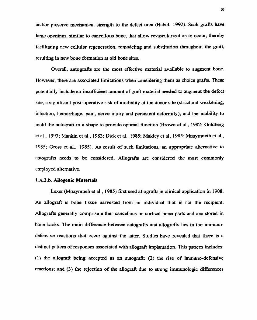
and/or preserve mechanical strengh to the defect area (Habal, 1992). Such grafts have
large openings, similar to cancellous bone, that allow revascularization to occur, thereby
facilitating new cellular regeneration, remodeling and substitution throughout the gr&
resulting in new bone formation at old bone sites.
Overall, autografts are the most effective material available to augment bone.
However, there are associated limitations when considering them as choice grafts. These
potentiaily include an insunicient amount of @ material needed to augment the defect
site; a significant post-operative nsk of rnorbidity at the donor site (structural weakenhg,
infection, hemorrhage, pain, nerve injury and persistent deformity); and the inability to
mold the autograft in a shape to provide optimal function (Brown et al., 1982; Goldberg
et al., 1993; Mankin et al., 1983; Dick et al., 1985; Makley et al, 1985; Mnaymneth et al.,
1985; Gross et al., 1985). As result of such limitations, an appropriate alternative to
autogr& needs to be considered. Allografts are considered the most cornmonly
emplo y ed alternative.
1 .A.2. b. AUogenic Materials
Lexer (Mnaymneh et al ., 1 985) first used allografts in clinical application in 1 908-
An allograft is bone tissue harvested fiom an individual that is not the recipient.
Allografts generally comprise either cancellous or cortical bone parts and are stored in
bone baaks. The main dserence between autografts and allografts lies in the immuno-
defensive reactions that occur against the latter. Studies have revealed that there is a
distinct pattern of responses associated with allograft implantation. This pattern includes:
(1) the allograft king accepted as an autograft; (2) the rise of irnmuno-defensive
reactions; and (3) the rejection of the allograft due to strong imrnunologic differences

(Fi-iedlaender et ai., 1985 and Horowitz et ai., 1987). Predominantly, the host immune
response is inflammatory and can occur as early as 5 days (Katthagen, 1986). Vascular
ingrowth occurs much more slowly and less extensively than with autogr*. In
addition, these vessels becorne blocked with inflanmatory cells resulting in necrosis.
However, despite these occurrences, a limited amount of oew bone is still formed prior to
necrosis. An accepted ailograil may demonstrate mild callus and repair, although Mted ,
but such repair usually results in nonunion or delayed union and fatigue fractures (Habal,
1992). Consequently, the clinical usefulaess of employing allografts for reconstruction is
questionable and numerous problems associated with using them remain unsolved; such
as the high risk of infection (Hepatitis, AIDS, and bacterial contamination). Furthemore,
the extent of care required today for choosing, checkhg and storing allogenic transplants
makes this technique suniciently expensive that cost supercedes usefulness (Katthagen,
1986).
1.A.2.c. Xenogenic Graf'ts
Another alternative to an autografi is a xenograft. A xenograft is bone harvested
£iom another species that has been subjected to rigorous preparation prior to
implantation. Many methods exist for preparing xenografts, which include fkozen cal f
bone, tieeze-dried calf bone, decalcified ox bone, and deproteinized bone (Hughes et al.,
1943; Hurley et al., 1960; Nade et al., 1977; Salama, 1983). The Kiel bone is one of few
cornrnercially available xenografts prepared by deproteinking bovine caif bone using
hydrogen peroxide as the extracthg agent. It is weakly antigenic but lacks osteoinductive
capability (Heiple et ai., 1967). In fact, in 1970 Schweiberer showed that the Kiel bone
splinter hinders rather than promotes bone regeneration. As a result, the usefulness of the

Kiel bone spiinter is very controversial and only limited success has k e n reported more
recently (Katthagen, 1986). Xenogdb are essentially used as mechanical m e r to
prevent soft tissue ingrowth, which would otherwise iimit osteogenesis. However, to
facilitate osteogensis it is necessary to add components of a u t o m or autologous
marrow to the xenograft (Habal, 1992).
In summary, comparing the digerent bone g r a b available (autogenic. allogeaic
and xenogenic), the autogenic bone graft provides the best results, as there are no
immunlogical problems, its osteogenic capacity is excellent and resorption and
remodeling are quick and effective. However, the limited availability of autograft tissue
and the less than ideal allograft and allograft alternatives have driven the development of
artificial bone-substitute materials. These include the calcium phosphate based-
biornaterials.
1 .A.2.d. Synthetic Bone Substitutes
There has been a shifi in ernphasis placed on the use of gr& material (i-e.
autograh) to synthetic bone substitute implants in the last decade for the reconstruction
of bone defects (Rey, 1998). Particularly, a considerable effort has focused on developing
implant materials composed of calcium phosphates because of theïr close chernical and
crystal resemblance to bone minerai. In fact, calcium phosphate-based materiais have
been employed in medicine and dentistry for over 20 years in such applications that
inchde dental implants, periodontd treatment, alveolar ridge augmentation and
maxillofacial surgery. (de Groot, 1983, 1988; Hulbert et ai., 1987; Jarcho, 1981; Le
Geros, 1988; Le Geros et al., 1993). Consequently, due to the expanding application of

calcium phosphate ceramics, there is a need to investigate various properties that render
them suitable candidate bone-substitutes.
For a calcium phosphate-based ceramic to function successfully as a bone
replacement and or augmenting material it should satisQ certain physicai and biologic
criteria. Initially, if a calcium phosphate ceramic is used in a bone gr& procedure as the
material of choice it should (1) overcome the disadvantages associated with other grafiing
material types (Le- autografis and allografts) but, (2) poses the properties that render
traditional grafting material the superior choice. Consequently, the ideal bone gr&
substitue should: (1) be biocompatible and nonimmunogenic; (2) exhibit osteogenic
properties; that is, the material should actively stimulate the differentiation of
mesenchymai stem cells into active osteoblasts: a property referred to as osteoinductive;
(3) be osteoconductive by providing a ma& for new bone formation; (4) impart
structural strength, both in loaded or stressed sites; (5) be available in uniirnited quantity
and be large enough to be shaped into the size needed; and (6) produce a consistent
biological response that includes its biodegradation during bone healing (LeGeros et al.,
1995).
Several stoichiometries of calcium phosphates (i-e. Caio(P04)6(0H)z - hydroxyapatite, Caio(P04)(F)2 - fluorapatite. Ca3P0& - tricalcium phosphate,
Ca2.7Mgo3(P04)2 - magnesium whitiockite and Ca4(PO4h - tetracalcium phosphate) have
been învestigated for bone repair of which tricalcium phosphate (TCP) and
hydroxyapatite (HA) are the most common. TCPs have k e n formuiated as pastes,
particles, and discs for bone repair (Mors et al., 1975; Ohgushi et ai., 1990a; Nagase et
al., 1991 ; Nagahara et ai., 1992). However. the unpredictable biodegradation profile of

TCP is a troubling issue in bone grafting since TCP biodegradation within bone defects is
routhely not accompanied by bone formation (HoDinger et al, 1996).
Hydroxyapatite is the most extensively d e d calcium phosphate. Heating of the
hydroxyapatite crystals to 2 1 100°C fuses the crystals by the process of sintering and it is
in this form, as a ceramic, that HA has received the most attention. Laboratory derived
HA has biomedical appeal due to apparently sunilar chemistry and in vivo behaviour of
naturai m. Consequedy, an extensive senes of prechhd reports hvolving use for
skeletal applications have been generated. Positive reviews fiom such repom have
demonstrated the suitability of using HA to repair bone (Holmes et al., 1979; Barrows et
al.. 1986; Geesink et al., 1990; Constantine et al., 1992; Frayssinet et ai., 1992; Brown et
al., 1994; Brekke et al., 1998). At present, HA as well as TCP in various forms have FDA
approval for use in bone repair devices and coatïngs on dental and orthopaedic implants.
It is evident, therefore, that calcium phosphates are biocompatible, non-immunogenic and
osteoconductive. Table 1.1 (modified fiom Hollinger et al., 1996) lis& the various HA
and/or TCP-based ceramic products that are distributed in the United States.
Table 1.1 Ceramic Bone Substitutes Distributed ia the United States
Product and Description S ynthograft: TCP Augment: TCP Orthogra!?: TCP Comments: These producrs are particutates and biodegr~dable and should no& be used
Company Johnson and Johnson, Somerville, NJ Miter, Worthington, OH Dupuy, Warsaw, IN
periodontal diseasee Hapset: TCP + calcium sulfate Lifecore Biomedical, Chaska, MN Comments: This product is prepared as a paste for insertion into dental extraction. OsteoGen: Synthetic H A ProOsteon: Coralline-derived HA Comrnents: These products are partieulate
Impladent, Hol~iswood, N'Y Interpore International, Irvine, Ca

and nonbiodegradable and should be used in nonstress-bearing areas, such as periodontaf defections. ProOsteon has been Food and Drug Administration approvedfor use in rneta~hyssal defects. Coilagraft: H A (65%) + TCP(35%) combined with 95% Type 1 bovine collagen and 5% Type III Comments: This pro& is supplied in strips. and the manufacturer suggests that for besr resufts, autogenou &food should be added Application sites recomrnended are spinal_firsium and bone cystic cavities. The collagen and TCP should biodegrade with time.
The principal limitation of calcium phosphate implant materials is their
mechanical properties. These materials are quite brittle, have low impact resistance and
relatively low tensile strength when compared with bone and metais (Table 1.2) (Jarcho,
198 1).
Table 1.2 The Mechanical Properties of Bone, Metallic and Calcium Phosphate Implant Materials
Consequently, this has led to the coating of various rnetals with calcium phosphate in
order to provide the mechanicd properties necessary at the implant site (LeGeros et al.,
Modulus (lo6 psi)
Cortical bone Cancellous bone
MetaIs 3 1 6 L Stainiess Cor-Cr alloy Titanium
Calcium Phosphates Porous Dense
Tensile Strength (10' psi)
Material
Bone
Compressive Strength ( i 3 PS~)
20 6-9
- - -
1-10 30-130
1 0.0 0.5
80- 145 97 50
0.36 10-28
2 -
3 0-40 30 16
5 5-15

1995), while still possessing the advantages of calcium phosphates that include fast bony
adaptation, absence of fibrous tissue, îïrm implant-bone attachent and reduced healing
time (Kay, 1992). However, during high temperature (21500°C) plasma spraying, a
typical coating process, ceramic contaminants, such as nonhydroxyapatites, may be
formed on the surface of the metal prosthesis. These contaminants are chemically less
stable than HA and therefore, could biodegrade, leaving voids throughout the interface,
resulting in the loosening and loss of the prosthesis (LeGeros, 1991). Therefore, to
overcome the poor mechanical properties of calcium phosphates demonstrated at implant
sites, calcium phosphates prepared in a porous form have been investigated. The rationale
for using this form is that the porous form should permit bony ingrowth thereby
reinforcing and stabilizing the implant (de Groot et al., 1 988). Also noteworthy is that the
porosity of a calcium phosphate bone substitute infiuences its biological performance in
vivo, since the rate and distribution of osteogenesis around and throughout the implant
will be effected by size and nuniber of interconnecting channels (LeGeros et al., 1995). It
has been reported that pores of approximately 100 p m in diameter cm provide a
fiamework for bone growth hto the pore volume (Holmes et al., 1988) and becorne easily
vascularized, which is vital to the maintenance of the implant (LeGeros et al., 1995). In
addition, more interconnecting channels can lead to better bone penetration throughout
the bulk material (LeGeros et al., 1995) which enhances the mechanical stability of the
implant at the defect site (Nunes et al., 1997). ProOsteon (interpore International, IMne,
CA, USA) is a FDA approved coral-derived, porous HA ceramic that may be used to
restore nonload bearing metaphyseal defects. HA in this fonn and architecture (500 pm

pore size range and high interconnecting porosity) supports bone ingrowth thereby
pennitting bone-implant stability (Hollinger et al., 1996; Nunes et al., 1997).
Since any practical application (i.e. clinical) of calcium phosphate bioceramics
involves contact with a physiologicai environment., it is important, therefore, to know the
stability or biodegradative potentiai of the implant material. There are essentidy hvo
ways in which a material can degrade, (1) solution mediated and (2) ce11 mediated
processes (Jarcho, 1981). Both processes are believed to be influenced by the
crystal/composition and structure of the material (de Bniijn, 1993). Particdarly, the type
of phase or phases present in the calcium phosphate and the degree of micro- and
macroporosities have significant infiuence in the degradation rate of the material. The
difference in composition and crystallographic structure of such commonly investigated
calcium phosphates such as hydroxyapatite (HA), B-tricalcium phosphate (B-TCP) and a-
tricalcium phosphate (a-TCP) is reflected in the daerence in their stability and
solubility. The order of their relative solubility is a-TCP > P-TCP > HA (LeGeros et al.,
1995). There are different phases of calcium phosphates and depending on their
application, one phase or a combination of phases is used as a potential bone replacement
material. Calcium hydroxyapatite (HA), tricalcium phosphate (TCP) and ratios of the two
OHA/TCP), are the more commonly investigated calcium phosphates for biomedical
application (de Bmïjn, 1993; LeGeros., 1995). HA, Caio(P04)6(OH)z, shows good
biocompatibility when implanted in either soft tissues (Jansen et al., 1985; van
Blitterswijk et al-, 1991; Ogiso et al., 1992) or hard tissue (Jarcho et al., 1977; Denissen
et al,, 1980; de Groot 1981; van Blitterswijk et al., 1985) and has also been shown to
form a strong and intimate bond with bone (Jarcho et al., 1977, 1981; Denissen et al.,

1980). TCP, Ca3(P04)2, has aiso been reported to possess good biocompatible properties
(Nerry et al., 1975, Klein et al., 1983, 199 1 ; van Blitterswijk et al., 1989) but dissolves
rapidly in vivo. (Klein et al., 1983, 1990). CP composites (Le. W C P ) are among the
most widely investigated CP cerarnic biomaterials due to the benefits of their combined
properties (de Bmijn, 1993). These materials, called biphasic calcium phosphate
ceramics, offer several distinct advantages over either phase done- HA is characterized as
relatively bioïnert; that is, it is the more stable phase in physiological envkonment
compared with TCP (de Groot et al, 1992). Consequently, the biphasic materid has the
ability to provide a matnx for new bone growth due to the presence of HA, as well as
biodegrade due to the presence of TCP which is relatively unstable in physiological
solution (LeGeros et al., 1995). Some authors have studied the effectiveness of various
ratios of HA and TCP (Flately et ai., 1983; Berry et al., 1986; Eschenroeder et al., 1987;
Frayssinet et al., 1993). Different combinations of HA and TCP cm be fabricated to
attempt to control the degradation profile of the implant material.
In addition to the importance of solution mediated dissolution in the degradation
of calcium phosphates, there has been evidence published that demonstrates macrophage
and muitinucleated ce11 mediated degradation (van Blitterswijk, et al, 1985, 1989) and
osteoclastic mediated degradation (Davies et al., 1989; Muller-Mai et al., 1990; Daculsi
et al., 1 WO&b, 199 1; Bauer et ai., 1991). Osteoclasts have very precise function and their
activity is critical to the maintenance of the skeletal system, as well as their potential
participation in degrading CP bioceramics. The activity of osteoclasts related to the
overall bone remodeling process can only be rneasured in vivo but the activities of
individual cells is difficult to assess. In the last decade seved groups have introduced

different types of culture systems to study the events occuming during biodegradation of
CP bioceramics (Jones et al., 1984; Ogura, 199 1; Davies et al., 1993; Benahrned et al.,
1994). There is convinchg evidence of osteoclastic resorption in viîro of thin films or
disks of HA (Davies et al., 1992; Fujimonetal et al., 1998) and biphasic HA@-TCP
composites (Davies et al., 1993; Soueidan et ai., 1995). However, there is no evidence
to-date that demonstrates osteoclastic resorption of 3-D prous CP sca.Eolds. Certain
classical morphotogicd and histochemicd characteristics of osteoclasts such as multi-
nuclearity and tartrate resistant acid phosphatase (TRAP) activity may provide supporthg
evidence for osteoclastic phenotype (Davies, 199 1 ), but there are not considered reliable
markers of osteoclastic differentiation (Hattersley et al., 1989).
Currently commercially available synthetic bioceramics can only be used as
filling matenai or as supportïng scaffold without osteogenic capacity. However, to render
such bioceramics osteoinductive, invenigaton have sought to reconstitute the bioceramic
with growth factors or osteogenic proteins that are able to induce or irnprove bone
regeneration. Bone morphogenic protein (BMP) is a glycoprotein present in bone ma&
that plays an important role in both condrogenesis and osteogenesis in embryonic as well
as in post-fetal life (Urist, 1997). Large critical size defects have been successfÙlly healed
by naturaily occwring or recombinant BMP that was carrïed by a suitable delivery
vehicle (Johnson et ai., 1988; Cook et aI., 1994; Cook et al.. 1997). Bioceramics have
been used as carriers of BMP in experhental studies (Lindhoh et al., 1993). Studies
performed by Gao et al., (1996) used a composite bone substitue composed of porous
TCP, BMP and type IV collagen to repair a diaphyseal segmental defect in the tibia of
sheep. A healing superiority was observed when the segmental defect was filled with the

composite bone substitute than with TCP + coiiagen alone. This study showed that the
composite possessed both osteoconductive and osteoinductive properties.
It is evident that there are impressive positive reviews of the use of calcium
phosphate as a suitable bone graft materiai. However, large defects, those resulting fiom
orthopaedic injury or removal of osteosarcornas, requke bone regeneration to occur on a
larger scale where the use of auto/allogenous gdb or synthetic implants are not
satisfactory. Consequently, a new approach to healing bone trauma, called bone tissue
engineering, has emerged to deal with the Limitations of traditional bone transplantation
procedures.
1.B. Tissue Engineering
1.B.1. General
The loss or failure of an organ or tissue is a fiequent, devastating and costly
problem in human health care. For example, every year, millions of Americans suffer
tissue loss or organ failure that result in total national health care costs for patients that
exceed $400 billion per year (Langer et al-, 1993). Arnong these patients, approximately
8 million surgical procedures are preformed annually to treat the disorders (Langer et al.,
1993) which include using implants. In the US alone, about 140 000 artificial hip joint
implants and 20 000 knee prostheses are implanted per year and more than 100 000
patients with relevant defects in joint cartilage are known (Minuth et al., 1998). It was
common up to now to use metal prostheses for replacing hip joints but such materials
usually result in major problems that include implant loosening, inappropriate
degradation, infiammation and blood clotting (Minuth et al., 1998). In order to dirninish
costs of transplantations and pst-surgical complications associated with organ and tissue

repair a new field of study has emerged to provide an alternative solution to tissue
creation and repair. Tissue engineering is an interdisciplinary field that combines the
principles of engineering and the life sciences toward the development of biological
substitutes that aim to restore, maintain, or improve tissue fiction. The concept of
tissue engineering was fust established in 1987 at the US National Science Foundation in
Washington DC. The general strategy that has k e n adopted for the creation of new tissue
involves placing cells on and within matrices. The general strategy involves isolating
cells fiom the body and applying them to a matrk in an in viîru environment. In this
environment, the celis are allowed to grow and differentiate throughout the matrix. The
cells attached to the matrix can then be implanted and become incorporated into the body.
In the body, the matrix can now function as a tissue replacement material and encourage
a faster rate of tissue repair.
l.B.2. Bone Tissue Engineering
At present, bone is the second most transplanted tissue in the USA and Europe
(Martin et al., 1997), consequently, tissue engineering offers a fascinating new alternative
to traditional solutions of bone repair. The underlying concept of bone tissue engineering
involves isolating bone marrow cells, containhg the osteogenic ceii population, fiom a
patient, expanding the population in ce11 culture and seeding them onto a scaf5old. This
materiaVbiologica1 composite, or TE construct could then be grafted back into the same
patient to fûnction as replacement bone tissue.
Advances in ce11 cuIture technology have been fbndamental in establishing the
tissue engineering field since an in viîro phase is key to perfonning the TE strategy.
Currently, bone tissue engineering approaches focus on using mesenchymai stem cells

(MSC) for regeneratïng bony defects MSC have the capacity to differentiate into various
ce11 types that include osteoblasts that give rise to bone (Caplan, 1991). Minuth et al-
(1998) describes three principle steps that must be achieved during the in vitro stage.
Applying these steps to the bone tissue engineering strategy would involve (1) ob-g
sufficient multiplication, proliferation and spreading of mesenchyrnal stem cells (MSC)
on a tissue culture substrate; (2) seeding the expanded ce11 population on a suitable
scaffold and (3) maintainine the differentiated phenotype long-term.
MSCs can differentiate into a number of phenotypes that include bone, cartilage,
tendon/ligament, muscle, marrow and connective tissue, by entering discrete
differentiation pathways. Two different strategies can be employed to achieve MSC-
mediated tissue repair. The first strategy uses the culture-expanded MSCs in their
undifferentiated state. With the presence of local environmental cues, the MSCs wiU then
differentiate into the appropriate ce11 lineage that is responsible for the tissue regeneration
process. The other strategy involves using culture-expanded MSCs that have been
directed ex-vivo into a specific lineage prior to implantation, thus accelerating the healing
process. In the case of bone regeneration, the culture can be directed into the osteogenic
lineage by the addition of various growth factors, including dexamethasone, or cytokines
(Bruder et al., 1994; Jaiswal et al., 1997). Regardless of the strategy chosen, it is essential
that the regulation of MSC proliferation and differentiation be maximized at the in vitro
stage. Maintainhg ce11 differentiation and proliferation is successfdly achieved by
tramferring the tissue carriers into culture containers that are pennanently perfûsed with
fiesh culture medium (Minuth et al., 1992). Continuous elimination of waste products

that would otherwîse be detrimental to cellular fiuiction is alsu achieved by perfusion
(Sittinger et al., 1996).
In addition, the in viîro phase of the TE strategy involves the development of
suitable scaffolds for MSCs seeding and later, in vivo, new tissue support. The ideal
delivery system for osteoprogenitor cells at a bone trauma site wodd be one that niimics
the naturai morphology of bone. The appropnate carrier could allow a three-dimensional
distribution of cells m MCTO thereby accelerating bone healing in vivo. Thus most research
into bone grafting has focused on duplicating the structure and material of trabecular
bone using natural and synthetic structures (Panda et al., 1998; Holy et al., 1998).
l.B.2.a. Macrostructure of Trabecular Bone
The natural open pore geometry of trabecular bone macrostmcture provides a
good starting point for the design of scaffotds for bone tissue engineering. Human
trabecular bone is generally anisotropic, implying that the bone does not appear identical
when held in one position compared to its appearance rotated by 90' (Martin, 1984).
Trabecular anisotrophy is a result of gravitationai stresses imparted by the skeleton. The
upright and bipedal form of human locomotion results in vertical trabeculae being thicker
(200 pm) than horizontal trabeculae (Tobin, 1955). These vertical and horizontal
trabeculae form a highly connected network. Isotropie trabeculae can be found in areas
where the trabeculae are randomly arranged. Figure 1.3 illustrates areas of isotropie and
anisotropic trabeculae that are present in the neck of the human femur.

Figure 13 . Light micrograph showing isotropic and anisotropic areas of the trabeculae in the neck of the femora (Tobin, 1955).
The work of Ward (1838) compartmentalized the types of trabecuiations in the
femora. The medial, M. is located fiom the upper part of the shaft to the articular surface
of the head. The lateral group, L, is situated below the greater trochanter and the upper
surface of the neck. The intertrochantenc arches I l and Ig are shown in Figure 1.4, dong
with M and L.

Figure 1.4. Diagram showing the directions of the trabeculae in the femora (from Instructional Course Lectures, The American Academy of Orthopaedic Surgeons. Vol 10, p.2 15, 1953 .)
The area between L, M and Iz forms a triangular area of structurally weak trabeculatiom
known as Ward's triangle. It was the extensive work of Whiteshouse and Dyson (1974)
and Martin (1984) who described the trabecular bone width and porosity in these
compartments, respectively. Table 1.3 lists the porosity and trabeculae width measured
Table 1.3 Averages of Porosity and Trabeculae Width
1 Area 1 Porosity 1 Ttrrbeculae width
1 Interior of Intertrochantenc / 84.5 I 1.8 1 O. 18 + 0,024
Lateral htertrochanteric arches
- -
79.0 + 5.0 88.2+ 3.2
Arches Greater trochanter
0.23 14 0.053 O. 14 + 0.029
90.51 1 .O 0.3 1k 0.026

Currently, researchers strive to design materiais that have simila. architecture to
trabecular bone in order to mimic the replaced a d o r diseased tissue. Animal studies
have been conducted with the use of porous implants positioned in large defects of long
bones (Hoodendoorn et al., 1984; Daculsi et al., 1990b; Nunes et al., 1997). The results
suggest that there is a f5rm union established at the bone-implant interface. However, the
authors found that f i e r 35 weeks, only one third of the available pore volume was
ingrown with bone. This partîai ingrowth of bone might be attributed to sequestered pores
inside the ceramic; that is, the impiants used had minimal interconnecting pores.
Histological kdings codhmed that bone ingrowth was pronounced near the edges of the
implants in contact with the existing or newly formed bone with no bone growth toward
the centre of the implant (Hoogendoom et ai., 1984). Such implants effectively provide a
scaffold for bone growth but the level of interconnectivity of the implant limits the extent
of bone ingrowth.
1.B2.b. Candidate Scaffolds for Bone Tissue Engineering
Due to the hadequacies of bone gr& that include their heaith related problems
and cost of implementation, there has been a shift in experimental paradigm from the
development of materials to replace or augment bone tissue to materials combined with
cells that can stimulate the body to regenerate tissue more effectively and rapidly. While
bone tissue has been grown in culture for many years, the ideal bone TE construct has yet
to be found. There are various laboratories, worldwide, which are embarking on research
programs directed at bone tissue engineering, with the emphasis on designing the suitable
bone TE constnict-

To asses the potential success and in vivo requirements of a TE scaffold in an
orthotopic site, research groups predominantly use ectopic testing, which involves
implanthg the candidate material into subcutaneous or intramuscular sites (Ohgushi et al,
1989, 1992% b; Goshima et al, 1991% b). Porous calcium phosphate ceramics are the
choice biomaterial used to assay the osteogenic potential of mesenchymal stem cells
(MSC) at ectopic sites primarily because they display excellent osteoconductive
properties. Therefore, the combination of bone marrow derived cells and a calcium
phosphate-based scaffold results in a TE construct that possess both osteogenic and
osteoconductive properties. Results nom such ectopic testing in rats, using a ceramic
composed of 60% HA and 40% TCP having mean pore size of 400 pm, provided by
Zimmer Inc. (Warsaw, lN), combined with rat rnarrow ce11 suspension showed
osteogenesis in the surface pore region at approximately 3 weeks and evidence of
vascular invasion and palisade arrangement of osteoblasts within the pores (Ohgushi et
al., 1 WOa). The ceramic alone subcutaneously implanted, showed no bone formation.
instead, many of the pores were filled with fibrous connective tissue (Ohgushi et al,
1990a). Interpore 200 (Interpore International, bine , CA), as it is referred to in
literature, has also been investigated as a candidate TE constmct. It is produced by
hydrothermal conversion of calcium carbonate skeleton of marine coral (genus Porites).
The resuitant materid is a fiilly intercomected porous HA matrix having an average pore
diameter of 200 W. Both interpore 200 alone and Interpore 200 combined with rat
marrow cells have been implanted in subcutaneous sites in snygeneic rats (Ohgushi, et
al-, 1990a,b, 1992a,b, c; Yoshikawa et al., 1992). Consistent with the resuits using the
Zimmer Inc. material, bone did not form in any implant without marrow cells but bone

did form in all implants with marrow cells after 4 weeks (Ohgushi et al., 1990% 1992%~).
Bone formation occurred initially on the surfaces of the pore w d s . In addition, it was
also reported that bone grew toward the centres of the pores, which was made possible by
the interconnecting porosiq. Other groups have adopted the common TE strategy ushg
biodegradable polymer systems (Ishaug-Riley et al.' 1997; Kadiyala et al., 1997; Holy et
al, 1998) have observed similar results that are seen in ceramic-based TE systems. It is
ciear that bone formation occurs when fiesh marrow is added, but the rate and extent of
healing is a fünction of the amount of marrow and the number of osteoprogenitor cells
residing therein. Consequently, this has led to the use of expanded bone marrow derived
cells as the ce11 population in the in vitro stage. The work of Ishaug-Riley et al. (1 997)
investigated in vivo bone formation on porous (150 - 300 p m and 500 to 710 pm)
biodegradable poly (DL-lactic-CO-gl ycolic acid) foams combined with marrow stromd
osteoblasts (expanded bone marrow denved cells) at an ectopic site in rats. Histological
imaging revealed the formation of mineralized bone-like tissue and capillary invasion in
the polymer/cell composite of the two types of pore size ranges used within 7 days
postimplantation. Uemura et al., (1998) and others (Goshima et al., 1 Wla, b; Yoshikawa
et al., 1996) have demonstrated the strong osteogenic potential of expanded bone marrow
derived cells introduced into macroporous ceramics to fom bone as early as two weeks
in vivo. In contrast, the fiesh marrow/grafl composite showed no significant bone
formation at two weeks. Such results suggest that an expanded ce11 population offers a
greater source of osteogenic cells, which is reflected in the amount of bone formation
observed at earlier time points.

To ultimately test the suitability of a cell/graft composite to reconsmict a bony defect
at an orthotopic site, an appropriate surgicai mode1 must be employed. To implernent the
TE strategy at orthotopic sites in animals, a critical-shed bone defect mode1 is used. The
work of Kadiyala et al. (1997) have demomtrated that a porous material of M C P ,
(Zimmer Inc.), combined with culture-expanded MSC to regenerate a cntical-shed bone
defect in rat femora. Their results revealed that MSC-loaded materials showed
sigdicantly more bone formation at 4 weeks and even more bone formation by 8 weeks
when compared with cell-fkee implants (Kadiyala et al., 1997). However, histological
findings revealed that bone grew preferentidy dong the implantmost interface but not
throughout the bulk material. Similar studies performed by Ohgushi et al. (1992% b, a, c)
reported comparable results with the same material, indicating that the HA/TCP ceramic
corn bined with expanded bone marrow stroma1 cells showed sufficient healing potential
for the treatment of massive bone defects. However, the lack of intercomecting pores
toward the centre of the material resulted in no bone formation in this area- Similar work
has been conducted using a polymer-based TE construct. Puelacher et ai. (1996) placed
PGA-fibre based materials combined with expanded bovine periosteurn-derived cells into
rat femoral sh& defects. Radiographie findings confirrned bone formation at the defect
site on the celvpolymer graft and at 12 weeks, new bone was observed bridging the
surgically created defects completely. In contrast, the animals that received cell-fiee
polymer gr& showed no significant bone formation.
1.B.2.c. Current Limitations of Calcium Phosphate (CP) Bone TE Scaffolds
To successfiilly hc t ion as a bone TE constnict, the candidate biomaterial should
satise certain additional criteria including those mentioned in section 1 .A.2.d. Central to

the TE strategy is designing the scaEold to mimic the lost andor damaged bone. Since
massive bone defects occurring in the long bones are the more challenging defects to fiU
with traditional grafts, a macroporous scaffold that imitates the threeaimensional bone
defect would then be the ideai replacement grafi. The macroporous scaffold would
facilitate bony ingrowth into the pores and subsequently irnpart positional stability, as
discussed in Wolford et al- (1 987). Architecture of the scaffold, therefore, becomes
pivotai in the in vitro stage of the TE strattegy. In the in v&o phase, the engineered
scafFold shouid possess a fiamework for ceii attachent, expansion and differentiation on
and throughout its structure. To accomplish this, the scafEold should have a fully
interconnecting porosity and a pore size diameter that wouid encourage bone ingrowth
into the pore volume- In addition, the appropriate ce11 culture methodology is important
in governing cellular behaviour on the scafTolds. It has k e n demonstrated that scaffold
macroporosity is a critical factor in cell migration and bone matrix elaboration in vitro
(Rout et al, 1987). Matrices with a nominal pore size of 200 Pm (Rout et al, 1987),
resulted in occlusion of pores by migrating ceiis, while similar scaffolds of 500 p
nominal pore size pennitted 3-D tissue growth in vitro (Yoshikawa et al., 1996).
However, Mainard et al. (1996) have reported that a pore size of 80 Fm is necessary for
bone ingrowth in vivo for various calcium phosphates cerarnics (particularly, HA and
HA/TCP systems) implanted into the rabbit femur. Consequently, these results reveal that
the optimum pore size required for bone ingrowth differs in the in vitro and in vivo
environments.
The degradative capacity of a carrier construct is also an important property for TE
applications. As mentioned previously, a biomaterial can be degraded in two ways;

solution mediated and cell-mediated processes. Osteoclastic resorption, a cell-medîated
process, is favored over dissolution because the material becomes replaced by new bone
during the normal course of bone remodeling events in vivo. However, a scafTold that can
support bone ingrowth but also degrade in a marner that coincides with the rate of bone
formation would also be ideal. Polylactide and its derivatives are biodegradable polymers
that have k e n extensively snidied for tissue engineering applications (Holy et al., 1996;
Kadiyala et ai., 1997; Ishaug-Riley et al., 1997). These poIymers can be formed into
three-dimensional structures that mimic the architecture of actual tissue and possess the
appropriate porosity for bone ingrowth. However, despite their capacity to biodegrade by
hydrolysis or by cellular pathways, they lack the mechanical strength to withstand
loading in bone. The commercially available calcium phosphate biomaterials
rnanufactured by Interpore International (Interpore 200 and Pro Osteon 500) fûnction
successfully as bone substitutes. Harvested fiom marine cord exoskeletons, Interpore 200
and Pro Osteon 500 have tme interconnected porosity to ensure complete bone ingrowth.
Through a patented process, a thui calcium phosphate layer is formed on the outer surface
of the calcium carbonate pores and throughout the entire implant. However, despite the
fact that ProOsteon 500 has the appropnate pore size, 500 p, for cell migration in vitro,
the relative importance of dissolution or cell-mediated degradation, and whether this
coincides with the rate of bone formation, is currently unknown for this biocerarnic. As a
result of such Limitations mentioned above, the scaf5olds currently investigated for TE
application do not entirely fùlfill the requirements of a TE constmct since their in viîro
characterization has not been thoroughly investigated.

2. RESEARCH RATIONALE
The underlying concept of bone Tissue Engineering is that bone marrow cells can be
isolated f?om a patient, the ce11 population expanded in ce11 culture and seeded onto a
carrier and the material/biological composite, or TE co~~~ tn i c t , grafted into the same
patient to function as replacement tissue. While bone tissue has been grown in culture for
many years, the ideal carrier for a bone TE constnrct has yet to be found. There are
ceramic-based biornaterials commerciaily available that have been and are currendy
being used in bone tissue engineering research to demonstrate their suitability as TE
consmicts. These materials, however, either lack the interconnecting macroporosity
and/or controiled degradation that make them successfirl bone TE constructs.
The TE strategy comprises an in vitro phase followed by an in vivo phase.
Characterizing the TE scaEold's biological behaviour in vitro has yet to be thoroughly
addressed. The physicai properties (architecture, macro/microporosity, and
intercomecting macroporosity) and the biological behaviour (or the afçiity of the
scaf3old for bone marrow-derived cells) of the TE scafZold in the in vitro phase shouid be
indicative of its success as an ideal TE constnict once grafted into the patient. There is a
need to characteriz a candidate bone TE scafTold in terms of its physical characteristics
so that it satisfies certain defined material properties that render it a suitable TE constnict.
Also, in the in vitro phase the TE scaffold should, through its physical properties, permit
the attachment of bone marrow-derived cells (BMDC) throughout its macroporous
structure, and allow these cells to proliferate, differentiate and elaborate bone matrix. An
important prerequisite is optimal ce11 coverage and attachent be attained through

employing the ideal ceil culture conditions. It is proposed that the ideal conditions to
achieve these optimums would be a dynamic ce11 culture bioreactor that approximates, as
closely as possible, the conditions to which BMDC are exposed in vivo; that is, allowing
continuous flow of medium throughout the porous structure with the goal to accelerate
ce11 proliferation that would otherwise not be attained in static culture conditions.
3. HYPOTHESIS
Intercomecting macroporosity will be the critical factor in detennining the
usefulness of a 3-dimensional calcium phosphate as a bone tissue engineering scaffold in
the in vitro stage of the tissue engineering strategy.
4. OBJECTIVES
4.A. To characterize the macroporosity and intercomecting rnacroporosity of the
calcium phosphates supplied.
4.B. To use different 3-D calcium phosphates, having different macroporosities
and interconnectiag macroporosities, as rat bone marrow ce11 culture substrates in order
to determine whether the distribution of bone fonned in vipo will be a product of their
macrostnicture.
4.C. To develop a method to culture rat bone marrow ceils in 3-D fluid flow
environment to enhance bone matrix elaboration on the cdcium phosphate scaEolds
provided.

5. MA'IERLALS & METIIODS
S.A. Methods of Characterization
S.A. 1. Provision of Cakium Phosphate Samples
Five different types of 3-dimensional porous calcium phosphates were
investigated in this thesis for their suitability as tissue engineering construcl. They were
generously provided by three different sources and are referred to as Zimmer (provided
by Zirnrner International Inc, Warsaw, IN, USA), CAM40/60, CAM70130, 2CAM70/30
(received fiom CAM implants, The Netherlands) and CPP (-60ppi, -45ppi, -20ppi and - 1 Op pi) (O btained fkom the Sc ho01 of Materials Engineering, Y eungnam University,
Kyongsan, Kyongbuk, Korea). The 'ppi' extensions used to descnbe the CPP ceramics
describe the pore size in units of 'pore per inch'. The macroporous CPP scafTolds were
made using polyurethane (PU) sponge method. As part of the procedure, the PU is bumt
out and the resultant inorganic macroporous scaffold that is created has its pore diarneter
defined by the PU sponge diarneter, hence the use of 'pore per inch' units (Baksh et al.,
1998). The rnethodç of processing the Zirnmer and CAM Implant ceramics samples are
not described here due to confidentiality agreements.
5.A.2. Light Photography
Calcium phosphate samples were cut, ushg a diamond ciisc with a dental
handpiece, into blocks having dimensions of approxirnately 4 x 4 x 4 mm and were
viewed at various magnifications under a dissecting microscope (Wild M3Z, Type-S,
Heerbrugg, Switzerland). %y varying the light source, provided by an Intralux@ 5000
light box, over the sample surface, the 3-D configuration of the material was viewed as

well as debris formed during the cutting process. The excess debns was removed using
an Easy Dusterm spray (SPI Supplies, West Chester* PA, USA). Black & white
photographs of the CP blocks at 10, 15, 20 and 40x magnification were generated to
record the macroporosity and extent of interconnecting macroporosity of the calcium
phosphates supplied.
5.A.3. Powder X-Ray Diffraction Spectroscopy (XRD)
Powder XRD was used to confirm the identity, the cxystallinity and phase purity
of the solid CP biomaterials. A fülly automated Siemens D5000 Difiactometer System
was used for data collection. The system operated with Cu-ka radiation on 50kv/35 mA.
A Kevex SS Detector monochromatized the secondary bearn. A step mode was used
during the data collection with step size: 0.02O 2-theta and counting time of 2.0 S. The
scanning range was 0" - 55" (2-theta). Some samples were run 2-3 times to obtain
satisfactory sets. XRD diffiactograms provide information on phases present, phase
concentrations, amorphous content and crystallite size. Software supplied by the
manufacture of the Siemens D5000 Difiactometer System was employed to measure the
relative peak heights using a least squares method to obtain a quantitative estimate of
phase abundance.
5.A.4. Scanning Electron Microscopy (SEM)
As-received CP specimens were prepared for SEM irnaging to observe the extent
of the macro/microporosity and crystal morphology characteristic to them at high
magnification. Dry, as-received CP samples were mounted on specimen stubs using
adhesive glue. Approximately 3 nm layer of platinum was sputter coated with a Polaron
SC515 SEM Coating System onto the CP specimens which were then examhed at

various magnifications in a Hitachi S-2000 scanning electron microscope at an
accelerating voltage of 15 kV. The images generated were used to measure the
rnarco/micropore size range and intercomectivity characteristic of each CP type supplied.
S.A.5. Back Scattered Electron Microscopy @SE)
5.A.S.a. LR White Embedding Protocois
As-received CP samples, of each type supplied, were prepared for LRW
embedding. The specimens were kept in 7096, 80%, 90% aad 95% ethanol for 1 hour and
then immersed in 100% ethanol for 3 hours. A 1 : 1 mixture of LRW (SPI Supplies, West
Chester, PA, USA) and 100% ethanol was prepared to begin the LRW infiltrahg
process. Specimens were placed in this mixture for 1 hour and then subsequentiy placed
in 100% LRW for 1 week under vacuum. The final stage of the embedding process was
initiated by polymerizing the LRW resin by adding I drop of activator per 10 ml of LRW
resin. Sarnples were placed in rnoulds and then filled with activated LRW. This
configuration was kept in a bath of ice-cold water during the embedding process in order
to disperse the heat produced during exothennic polymerization of the resin.
Polymerization occurred in 10-20 minutes, after which the samples, having approxhate
dimension of 4 x 4 x 4 mm, were cut in half using an IsometTM Plus precision saw
(Buehler Ltd., Lake Bluff, II, USA). One of the halves was mounted on a SEM stub and
the exposed surface was polished manually using an EcometB 5 two speed g ~ d e r -
polisher (Buehler Ltd., Lake Bluff, Il, USA) with decreasing grit size paper (120, 240,
400,600, 1200 USA grit size). The polished surface was coated with approximately 1 nm
of plathum and backscattered electron images were generated. Following andysis, the
sampIes were stored in a sealed container lined with dry-rite.

5.A.S.b. Quantification of Macroporosity and Intercoanectivity
Polished LRW embedded as-received CP samples were used to quantiQ the
macroporosity and interconnectivity characteristic of each type of CP supplied.
Backscattered electron images were generated fiom the polished surfaces. However, the
entire surface area could not be imaged even at the lowest attainable magnification on
SEM (~35). Consequendy, various images were captured and montaged in Corel Draw
5.0 to reconstnict the entire surface area Using an image analyzing program (Sigmascan
Pro) the pixel intensity measured fiom the CP material, LRW resin and voids (areas not
filled with LRW) were recorded. The relationship between these intensities provided
measurements of macroporosity and interconnectivity.
5.A.6. Degradation Behaviour of CP Scaffolds
Twenty-four samples of each type of CP supplied were placed in 0.1 M Tris
BufYer (Appendix A) for 6 weeks to assess the degradation of the CP biomaterials in an
acellular environment. Samples were y-sterilized at 2.5 Mrads prior to experimentation.
For each week, up to 6 weeks, the pH of the buffer solution was measured using a pH
meter (pH meter 10 accumet@, Fisher Scientific). In addition, the calcium ion ([ca27)
concentration was determined by atomic absorption spectroscopy.
A CP sarnple of each type was prepared for SEM at each time point studied (1,4,
and 6 weeks) to observe changes in surface morphology as a result of degradation. For
preparing wet samples for SEM imaging, specimens were dehydrated in a graded series
of ethanol and cntical point dried from carbon dioxide in a Polaron CPD7501 Critical
Point Dryer. Kepresentative samples fiom each week were mounted on specimen stubs
and platinum coated for viewing in a scanning electron microscope .

5.B- Static In V i o Studies
S.B.L. Rat Bone Marrow Culture System
Primary bone marrow cultures have the potentid in shoa time periods to give rise
to a population of differentiating osteogenic cells that produce matrix that is
morphologicaily and biochemically distinguished as bone matrix (Maniatopoulos et al.,
1988). This in vitro technique with its cntical dependence on the differentiating cells at
the nibstrate surface can provide information on the formation of bone on synthetic
biomaterial surfaces and a characterization of the structures that are present at the
bonehiomaterial intedice. The description provided betow outlines the Rat Bone
Marrow Protocol developed by Maniatopoulos et al., 1988 and reviewed in Davies, 1996
that was adopted for this research work. Modifications to the protocol were made in order
to accommodate 3-D substrates.
S.B.2. Description of Static CeU Culture Configuration
5.B.2.a. Primary CeU Culture, Subculture & Initial CeU Seeding
At an animal facility, rat femora of a young adult male Wistar rat (approximately
120g) were aseptically removed and dissected fiee of adhering soft tissues following
cervical dislocation and placed in tubes containing 10X antibiotic (AB) solution. The
securely capped tubes containing the rat femora were transferred to a lamina flow hood
at a culture facility. The cleaned femora were soalced in 3 additional 10X AB washes, 10
minutes each time and then briefly washed in a tube containing 10 ml a-Minimal
Essential Medium (a-MEM). The epiphyses of the fernur were cut off to expose the
marrow cavity. Using a 10 ml syringe filled with culture medium, the marrow contents
were emptied into a 15 ml tube via a sterile 20G11/2 needle. The marrow contents were

thoroughly flushed out once the femur tumed white. This procedure was repeated for the
other femur. The harvested rat bone marrow ce11 suspension fiom a rat was transferred
into a sterile 50 ml conical tube. The final volume was adjusted to 30 ml and
supplemented with fieshly prepared ascorbic acid (AA) (50pg/ml), B-glycerophosphate
(BGP) (5 mM) and dexarnethasone @EX) (10-~ hQM). A 15 ml volume was pipetted in a
T75 flask and placed at 37°C in a hurnidified COz incubator (5% CO2 and 95% air). The
culture medium mas changed every 24 hours. This procedure was repeated for ai l
primary cultures.
On Day 5 of the culture, the prîmary rat bone marrow cultures was subcultured
using a trypsinization protocol that removes adherent cells. The prirnary culture medium
was aspirated; the culture rinsed twice with 10 ml phosphate buffered saiine (Ca-Mg fiee,
PBS-CaMg) each time. The b s e r was aspirated and 5 ml 0.01% trypsin was added to
the culture and the culture was incubated for 20 minutes at 37°C. The culture flask
contents were pipetted up and down several tirnes to release the adherent cells and then
washed with 5 mi senun contaullng medium to neutralize the trypsin. The ce11
suspension was pipetted in to a centrifuge tube (Blue Maxm 50 ml polypropylene conical
tube, Becton Dickson Labware) and spun down at 80-1 00g in a centrifbge (Omnifuge
RT, Canlab) for 10 minutes. The supernatant was aspirated and the pellet r emaihg was
resuspended with 10 ml of culture medium. The suspension was filtered through a 100
p m ce11 strainer (Cell strainer 100 pm Nylon sterildgamma-irradiated, Becton Dickson
Labware). The ce11 count was detemiioed using a Couiter counter. The maximum celi
seeding densities were prepared (Appendix B).

CP scafTolds were placed in the wells of a sterile 24-well microplate. A total
volume of 2 ml of a-MEM was placed in each well containiog the CP sample for 10
minutes. Prior to ce11 seeciing, the a-MEM solution was aspirated fiom each well. Using
the desired ce11 seeduig concentration, 1 ml of this solution was seeded on to the top
surface of each sample using a 10 ml syrhge fked with a 20G11/2 precision glide
needle? positioned at the centre of the sample (Figure 5.1).
24-well plate 3-D substrate with needIe positioned at centre
Figure 5.1. Ce11 Seeding on to 3-D Substrate
The culture was placed in an incubator mainbined at 37*C, 95% air and 5% COz for the
desired ce11 seeding tirne. After ceil seeding, each sample was transferred to a 15 ml
sterile po ly styrene round-bottom tube and replenished with fully supplemented culture
medium. This configuration was placed in the same incubator and re-fed with growth
medium every 24 hours until tennination. At termination, the well contents were rinsed
&ce in PBS-CaMg and a-MEM, respectively, prior to king fixed in Karnovsky's

fixative (Appendk C) ovemight. M e r ceii £kation, the samples were stored in 0.1 M
sodium cacodylate buffer (pH 7.4,4OC) until M e r analysis was performed.
Prior to al1 ceil cultures, CP samples were cut using a diamond disc-fitted dental
handpiece drill into blocks havhg approximate dimension of 4 x 4 x 4 mm and sterilized
by y-irradiation (2.5 Mrads).
5.B.2.b. Tissue Culture Substrate for Celi Seeding
To maximize ce11 adherence to the CP sampIes. the appropriate tissue culture
substrate needs to be empioyed. To determine the optimum substrate, two types of
culture substrates were use& tissue culture treated (TCT) and bacteriological-grade (BG)
24-well plates. The desired ce11 seeding density was prepared fiom 5-day primary bone
ce11 cultures, as described in Appendix B. Representative CP specimens were placed in
wells of both TCT and BG 24-we11 plates and soaked in a-MEM for 10 minutes. Prior to
ce11 seeding, the a-MEM solution was aspirated fiom each well. Samples were seeded
with the prepared seeding density for 1 hour. One well contained no sample as a control.
This cell configuration was placed in au incubator maintained at 37OC and 5% COz for 2
weeks. The ce11 culture was re-feed with tùlly supplemented medium every 24 hours
until tennination. At tennination, the samples were £ked in Karnovsky's fixative and
then prepared for SEM analysis. This experiment was repeated two additional times to
confïrm consistency in observations,
5.B.2.c. Ceil Adberence as a function of Seeding Time
To determine an appropriate ce11 seeding tirne, primary RBM cells were
subcultured on Day 5 and using the maximum ce11 seeding density, the cells were seeded
into wells of a 24-well microplate. The cultures were kept at 3?C, 95% air and 5% CO2

for 0.5, 1, 3 and 4 hours. At each time point, the media was aspirated fiom 3 wells and
the contents of the wells were trypinsinzed for 30 minutes. The cells £iom the aspirated
media (non-adherent cells) and the ûypinsinzed cells (adherent cells) were counted in a
Coulter counter. The results were plotted and the appropriate ce11 seeding time was
determined. This ce11 seeding time would be used in subsequent cultures involving 3-D
substrates.
5.B.2.d- CeU Adherence on 3-D substrates during Cell S d i o g
To assess ce11 colonization on 3-D substrates at the chosen cell seeding tirne, four
samples of the Zimmer-type, CAM Implant-type, and CPP-type were seeded with the
maximum ce11 seeding density attainable at subculture. Tissue culture treated substrates
were used as positive controls and bacteriological grade substrates were used as negative
controls. Each sarnple type was placed in the well of a BG 24-well plate. The cellç were
seeded, as described previously, for 1 hour. The side opposite the seeding surface of the
block piece was marked using a permanent marker so events only occming on the
seeding surface could easily be interpreted. After ce11 seeding, the culture was incubated
at 37°C in hurnidified atmosphere of 95% air and 5% CO* for the chosen ce11 seeding
time. Once the seeding time was anained, three samples of each CP type were placed into
a new well, thoroughly washed in PBS-CaMg for 10 minutes, trypsinized for 1 hour, and
a ce11 number was detennined using a Coulter counter. Following trysinization a sample
of each type was stained with Toluidine blue and viewed in a dissecting microscope to
observe the presence of remnant tissue componets. The wells containhg the samples
were also trypsinized for 1 hour. The ce11 quantity attached to the well plate and in the
medium after 1 hour was also counted. In addition, a CP sample was fixed with

Karnovslcy's fixative and prepared for SEM anaiysis to observe the morphology of the
cells colonizing the surface of the CP. AU critical point dried samples were mounted on
SEM stubs with the marked side of the block glued to the surface of the stub.
S.C. Dexamethasone (-) Cultures
To assess the osteoclastic resorptive potential of the CP samples supplieci,
specimens were placed in ce11 culture medium containing no dexamethasone (DEX-).
Bone marrow cells were harvested fkom rat fernom Four samples, each placed in the well
of a BG 24-well plate, was seeded with 2 ml of RBMD cells following the method
described previously. The cultures were incubated for 1 hour at 37OC in 5% CO2 and 95%
air, subsequentiy, each CP samples was placed at the bottom of 15 ml polystyrene round-
bottom tubes and replenished with DEX- culture medium. This configuration was
incubated for 4 weeks. At 1,2,3 and 4 weeks, a sarnple was rinsed in PBS-CaMg and a-
MEM three times, 10 minutes each, respectively, pior to being placed in Kamovsky's
fixative overnight. On the next day, samples were thoroughly washed in 0.1 M sodium
cacodylate buffer and prepared for SEM imaging.
5.D. Dynamic In Ufro Studies
5.D.1. Description of Dynamic Ce11 Culture Configuration
Bone marrow cells were harvested fiom rat femora and placed in the ce11 culture
system descnbed previously. On Day 5 the primary culture was subcultured and the
desired ce11 seeding density was prepared. Gamma-sterilized CP samples were placed in
the weiis of BG 24-well plates and washed with a-MEM for 10 minutes. The ce11
suspension was then seeded on to the top surface of a sarnple using a 20G11/2 needle.
This configuration was placed in an incubator maintained at 37OC and 5% COz for 1 hour.

At 1 hour, the sample was transferred to a sterile 50 ml polystyrene conical tube filled
with 40 ml of M y supplemented medium containing long-acting ascorbic acid
(Appendix D). The conical tube was tightened using a screw cap and placed in a 3-D
medium-rotating configuration. Cultures were incubated at 37OC in 100% air (or 0%
COî). All cultures placed in this system were re-fed weekly until termination.
The rotating system employed contaios four glass tubes; open at one end,
positioned in a manner that achieves 3-D flow of culture medium- Each g las tube was
designed to hold two 50 ml conical tubes. Each glass tube was sealed using a rubber
stopper. A motor, operating at 120 Volts and 0.10 Amps, k e d to the central shaft
holding the specimen modules, allowed the system to be rotated continuously at 50/60
cylces/s for the duration of the culture. The sample placed in each tube was stabüized
between stainless steel mesh wires cut to the same diameter as the tube. Figure 5.2
illustrates the design configuration
Figure 5.2. Dynamic Cell Culture Apparatus

S.E. Cell Colonïzation, Arrangement and Function in Static & Dynamic Culture Systems as a hct ion of Time
Calcium phosphates specimens were placed in static and dynamic culture
environments for 1,2,3,4,5, and 6 weeks to study bone tissue growth on and throughout
the their 3-D structure. For each week, up to 6 weeks, samples were washed in PBS-
CaMg, a-MEM and fixed in Kaniovsky's fixative overnight, At 1, 4 and 6 weeks.
samples were prepared for SEM and histology.
5.F. In Vwo Studies
5.F. 1. Surgical Procedures
Calcium polyphosphate scafKolds (n=8) were y-irradiated and implanted
aseptically in male Wistar rat (200-250g) femora under 4% haiothane, nitrous oxide and
oxygen (2: 1) anaesthesia. The implants were press-fitted into tram-femoral drill holes
made using a low speed dental bandpiece and 2 mm round bwr, and the incision was
closed using 4-0 polygylcolic acid sutures and skin staples. Each animal (n=4) received
one implant per femur and was allowed fidl activity postoperatively. In vivo implants
were fixed, after 1, 2, 6 and 23 weeks, by immersion in Karnovsky's fixative for 24
hours. For the rats sacrificed after 1 and 2 weeks, the rat femora were prepared for SEM
imaging and the left femora were processed for histology. Both femora of the rats
sacrificed at 6 and 23 weeks were prepared for histology.
S.F.2. Histological Preparations
S.F.2.a. In Vivo Samples
Excised rat femora were tnmmed to include the portion of the diaphysis
containhg the implant and immersed in 10% buffered Formalin (pH 7.2) ovemight.
Fixed samples were then placed in 14.4% EDTA in 10% Formalin (pH 7.0 - 7.2) for

approximately 4 - 5 weeks. The solution was changed every second day and the
decalcieing bone was kept on a Red Rotor rotating table (Hoefer Scientific Instruments,
San Fransico, USA). Decalcification was c o b e d by X-ray radiography of the
diaphysis containhg the implant- The femora containing the implant was lefi in ninnuig
water overnight to neutralize the decalcïfjring action of the formic acid. Decalcified
sarnples were then dehydrated through a graded series of aicohols. The final stages of the
dehydration process involved placing the femora in 1:l ratios of 10W0
methylbenzoate/lOO% ethanol and nnally, 100% methylbenzoate until the bone appeared
transparent. The femora were then infiltrated with xylene for 1 hours and then with
xylenelparafnn for 2 hours, followed by pure paratnn (surgiPath@ Blue Ribbon)
idiltration under vacuum at 59'C. Once the paraffin had hardened, thin sections (4 pm)
were cut usine an American Optical microtome (mode1 820) with a cutting angle set at
6.5'- The cut paraffin was floated in a heated bath of water (46 - 4g°C). The ribbons were
carefully mounted on acid clean glass slides (VWR CanLab, 1" x 3") then deparaffinized
3 times for 5 minutes in xylene, and rehydrated in decreasing concentrations of alcohol to
water prior to staining. SLides were then stained in Harris' Hematoxyiin (surgiPath@) for
5 minutes and counter-stained in Aqueous Eosin. A second series of ethanol washes were
performed, this t h e reversing the solution concentration back to 100%, finishing with a
wash in xylene. Coverslips were placed on the slides and mounted with Entellan
mounting media (Merck). Histological sections were examined by light microscopy
(Leitz, Heerbrugg, Switzerland) and colour pictures were taken using Ektachrome T64
coloured reversal film.

5.F.2.b. In Vitro Samples
Fixed calcium phosphate samples fkom in vitro experiments were infïitrated with
molten agar (2% aq), The agar solidified around and throughout the sample at room
temperature. The inNtrated samples were placed in 10% Formalin overnight to harden
the agar. On the next &y, this complex was placed in 14.4% EDTA in 10% Formalin
until the CP sample was decalcified, as confumed by X-ray radiography. Decalcification
took anywhere fkom 5-8 weeks depending on the sample type. Each mould containhg a
sample was processed for histology as described abve. Serial sections were made
through half the sample in order to observe the extent of bone growth throughout the
sample. The halfway point corresponding to approximately 2 nim into the sampie (total
length of the samples were approdately 4 mm). Histological sections obtained fiom the
halfway point of each sample were examùied by light microscopy and colour pictures
were taken of these sections.

6. RESULTS
6.A. Methods of Characterization
6.A.1. Light Photography of As-Received Samples
The macroscopic structurai appearance of the 3-D calcium phosphates supplied
was clearly visualized by Light photography, as shown in Figures 6.1A - 6.8A (following
pages). It was evident, at this mapification, h î there was a varying degree of
rnacroporosity associated between each CP type. Specificaily, the distribution and size of
the macropores throughout the CPP types varied as seen in Figures 6.5 - 6.8. At higher
magnificatio~ the ievel of interconnecthg macroporosity was obsewed, as shown in
Figures 6.1B - 6.8B. It is evident that the greatest degree of interconnections between
pores was associated with the CPP sampte types. Also apparent was that the PU sponge
method used to create the CPP material was successful in creating marcoporous scaffolds
of varying pore sizes as seen when comparing Figures 6.1 - 6.8 (following pages). The
Zimmer and CAM Implant samples appeared to have similar surface appearances. Their
surfaces were pitted with pore openings that showed minimaai connections between
neighboring surface pores. Varying the light over these samples reveded that the samples
had a certain degree of porosity associated with them since Iight, as seen wi?h the naked
eye, penetrated through the bulk of the sample.
The samples depicted in the light photographs were typical samples used in future
experiments. All samples were cleaned of excess debris with an Easy Dusterm and 6 -
sterilized (2.5 Mrads). The physical appearance (Le. coiour) of the samples was not
effected by the sterilization procedure.

Figures 6.1A - B. Light photographs showing the Zimmer d o l d as-ieceived. Field widîh = 24 mm for A and field width = 12 mm for B.
Fi yres 6.2A - B. Light photographs showing the CAM40/60 scaBold as-received. Field width = 24 mm for A and field width = 12 mm for B.

Figures 6.3A - B. Light photographs showing the CAM70f30 scaffold as-received. Field width = 24 mm for A and field width = 19 mm for B.
Figures 6.4A - B. Light photographs showing the 2CAM70/30 scaffold as-received. Field width = 24 mm for A and field width = 19 mm for B.

Figures 6.5A - B. Light photographs showing the CPPdûppi scaffold as-received. Field width = 24 mm for A and fieid width = 19 mm for B.
Figures 6.6A - B. Light photographs showing the CPP4Sppi scafZold as-received. Field width = 0.54 mm for A and field width = 0.27 mm for B.

Figures 6.7A - B. Light photographs showing the CPP-20ppi scaffold as-received. Field width = 0.54 mm for A and field width = 0.27 mm for B.
Figures 6.8A - B. Light photographs showing the CPP-1 Oppi scaffold as-received. Field width = 0.54 mm for A and field width = 0.27 mm for B.

6.A.2 Powder X-Ray Diffkaction Spectroscopy (XRD)
Pulverized as-received CP samples were analyzed utiiizîng an X-ray
difhctorneter to confinn identity, presence of crystaliine/amorphous phases and phase
purity. The results are presented in Table 6.1.
Table 6.1 XRD Results of as-received Calcium Phosphate ScafTolds
As-received CP 1 Crystabity Zimmer
CAM40/60
Crystalline h
Crystalline
Cry stalline
XAM70/30 Crystalline
The XRD spectra for the various samples are shown in Graphs 6.1 - 6.5 (following pages).
The experimental ciiffiaction patterns were compared with calculated ones based on the
structural data for HA, TCP (a and types) and P-CMP available in the ICDD-Database
(International Centre for Diffraction Data) (1998). Powder x-ray difiction patterns were
generated from as-received calcium phosphates fiom the different manufacturers
(Zimmer, CAM Implants, Sc ho01 of Materials Engineering, Yeungnam University,
Phases 2-phase mixture of HA and f!-TCP 2-phase system of HA and B-TCP 3-phase mixture of HA, and two polyrnorphous of TCP: P-TCP and a- TCP 2 component system of HA and a-TCP B - P ~ ~ Y ~ Y P ~
Note: This compound is known ro have 3 polymorphous: alpha, beta and gamma. They have d~xerent structures and d~pac t ion patterns.
Phase Purïty 60% HA
,40% W C P 40% HA 60% B-TCP 70% HA 30% TCP
70% HA 30% a-TCP Pure B-CMP (Ca- metaphosphate, ca(?o3)2

Korea) labeled (A) CAM40/60; (B) CAM70/30; (C) Zimmer, @) CPP and (E)
2CAM70/30. The XRD patterns revealed crystallinity and variable compositions. The
black arrows on (A), (B) and (C) correspond to the peaks characteristic to f3-TCP while
the remaining peaks indicate the presence of HA. The peaks marked with asterisks on (B)
and (E) indicate the presence o f a-TCP. The amount of a-TCP (wt %) found in (E)
2CAM70/30 was higher than in (B) CAM70/30. h p h @) shows the CPP sample that
corresponds to the XRD spectrum of Ca(P03)z, CMP (calcium meta-phosphate).

/ Graph 6.1 Powder XRD pattern of CAM40/60 !
1 - - - --- -- -- __ _. --- 1
Graph 6.2 Powder XRD of CAM70/30 1 i

Gmph -- - -
10 14 18 22 26 30 34 38 42 46 50 54
2 theta
6.3 Powder XRD of Zimmer sample ----__ -- -- - - - - - - - - -

Graph 6.5 Powder XRD of 2CAM70/30

6.A.3. Scanning Electron Microscopy
6.A3.a Micro and Macroporosity
Scanning electron microscopy was used to observe the morphological appearance
of the components that comprise the CP samples and the extent of macro/microporosi~
characteristic of each CP-type. Figures 6.9A - M and 6.10A - 1 are micrographs of
uicreasing magnification illustrating the surface morphology of the various CP materiais.
AU the CP samples exhibited a d a c e morphology containing both macro and
microporosity, as seen at low magnification (Figures 6.9A7 E, 1 and M and Figures 6. lOA,
DI and G) and at higher magnification (Figures 6.9D, H, L and P and Figures C, F and I),
respectively. The processing procedure used to create the porous scafSolds resulted in
fused calcium phosphate grains as seen in Figures 6.9C7 G, K and O and Figures 6.1 1A,
E and H that resulted in the microporosity characteristic of each CP type. The calcium
phosphate grains that comprise each ceramic type were clearly visualized at this
magnification (x5.OK) and it was evident that the size, shape and morphology of the
grains differ between CP types- Both the Zimrner and CAM Implant samples
demonstrated a heterogeneous surface. The Zimrner-type material constituted irregularly
shaped grains that were fused together. While the CPP materiai comprised cylindrically
shaped grains of varying sizes that were also fused together. Within the CAM Implant
sample types (CAM40/60, CAM70130 and 2CAM70/30), the calcium phosphate grains
appeared spherical. However, the 2CAM70130 sample had its microporosity created by
staggered leaflet structures positioned between spherical grains.

Figures 6.9A - P. Scanning electron micrographs of as-received Zimmer and CAM Implant scafEolds. Micrographs A- D, E - H, 1 - L, M - P, correspond to increasing magnification of the surfaces o f the as-received Zimmer, CAM40/60, CAM70/30, and 2CAM70/30 porous ceramics. The lower magnification micrographs (A, E, I and M) demonstrate the level o f macroporosity, while the individuai grains and microporosity are seen at higher magnifications. F.W. = 2.58 mm, 90 Fm, 18 pn and 9 pm for A, B, C and D, respectively. F.W. = 1.8 mm, 90 pm, 18 p m and 6 pn for E, F, G and H, respectively. F.W. = 2.25 mm, 90 pm, 36 pm and 18 pm for 1, J, K and L, respectively. F.W. = 2.25 mm, 90 pm, 18 pm and 6 p for M, N, O and P, respectively.


Figure 6.10A - 1 Scanning electron micrographs of as-received CPP samples. Labels A - C, D - F and G - 1 correspond to increasing magnifications of the CPP-45ppi, CPP-Zûppi and CPP-lûppi sample typcs, respectively. Micrographs A, B and C have increasing magnincations of x35, x1.00K and x5.OOK corresponding to field widths of 2.58 mm, 90 p and 18 p.m. The macropore size range and level of interconnectivity is clearly seen in A, D and G while in C, F and 1 the individuai grains and micropores comprising the CPP types are depicted.

SEM was also used to estimate the grain size, micro/macropore size range
characteristic of each type of CP. This method of pore size characterization was chosen in
preference to other methods such as mercury porosimetry because 1) it gave a direct
representation of the surface porosity available for bone groowth and 2) mercury
porosimetry is restricted to size evaluation of h e r sized pores (> 20 um) (Cameron et al.,
1976). Table 6.2 lists the micro/macrostructuraI properties of the porous ceramics.
Table 6.2 Micro/macrostructural Properties of the as-received scafEoIds
Maeropore size range
Ceramic
Zimmer
6.A.3.b. Interconnectivity
2CAM70/30 CPP-45ppi CPP-2Oppi CPP- 1 Oppi
Figures 6.10A - I show three different pore size ranges manufactured using the
PU sponge method (45ppi, 20ppi, l0ppi). At low mapification, (x35, Figures 6.10A, D
Average Grain Size [clml
and G), the continuous macroporosity in al1 three orthogonal directions is shown. This
Micropore sue range
7.8 7 7 7
high degree of pore continuity was not observed in the Zimmer and CAM Implant
[clml
scaffolds. The pore structure of these CPP scaf5olds was not uniform throughout the
[ P l 1.7 1 0.6 - 1-7
0.4 - 0.8 1 50 - 500
matrix. This observation was consistent with the Zimmer and CAM Implant samples.
50 - 400
2-5 1-2 2 - 7
W i h each sample-type, there were pore openings that appeared both round and
elongated. The intercomecting channels of the CPP-45ppi, CPP-20ppi and CPP- 1 Oppi
450 - 720 855 - 1335 1000 - 1600
were measured to be 325, 580 and 1000 pn on average, respectively. When comparing
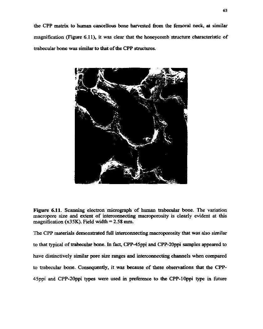
the CPP matrix to human cancellous bone harvested fiom the femoral neck, at similar
magnification (Figure 6.1 l), it was clear that the honeywmb structure characteristic of
trabecuiar bone was similar to that of the CPP structures.
Figure 6.11. Scanning electron micrograph of human trabecdar bone. The variation macropore size and extent of intenwmecting macroporosity is clearly evident at this magnification (x35K). Field width = 2.58 mm.
The CPP materials demonstrateci full intercomecting macroporosity that was also similar
to that typical of trabecular bone. In fact, CPP-45ppi and CPP-2ûppi samples appeared to
have distinctively similar pore sue ranges and interconnecting channels when compared
to trabecular bone. Consequently, it was because of these obsewations that the CPP-
45ppi and CPP-20ppi types were used in preference to the CPP-lOppi type in fitute

experiments. The Zimmer and CAM Implant ceramics did not reveal macrostmctural
simiiarities to human trabecdar bone.
6.A.4. Quantification of Total Porosity
Backscattered electron images were used to quant* total p o r o s i ~ that included
both micro and macroporosity of the CP materials supplied. In order to generate such
images in a scanning electron microscope, the samples were infïltrated with LRW resin,
polished and coated with a thin layer of piatinum- The images captured ~epresented the
surface area midway through the sample. At 50x magnification random spots were
imaged for each sample type. Al1 imaged areas measured 8.9 cm x 11.5 cm. Four images
were generated from three different samples of the same matenal type. This was repeated
for al1 calcium phosphates supplied.
Using Sigmascan Pro, an image-anaiyzing program, the pixel intensity associated
with the CP matenal, LRW resin and void areas were measured. On a backscattered
image, the CP material, LRW resin and void areas appeared white, gray and black,
respectively, as seen in Figure 6.12.

Figure 6.12. A typical back-scattered electron @SE) Mage generated from a LRW embedded CP scaffold. The BSE image shows a 2CAM70/30 sample infiltrated with resin. Similar BSE images were generated for Zimmer, CAM40/60 and CAM70/30 sample types. This BSE image shows areas of white, black and dark grey that correspond to the CP material, LRW resin and void areas, respectively. The void areas represent both micro and macropores. Cornputer-assisted image analysis was used to quan- the area corresponding to these colours. BSE images magnified at x50 corresponding to field widths of 1.8 mm were used to quantify the total porosity associated with each CP type.
The image andyzing program thresholds these colours with a pixel intensity range and
assigns a colour to each range. Table 6.3 lists the relationship between pixel intensity
range and material type.
Table 6.3 Relationship between pixel intensity range and material type
r Material 1 Sigmascan Pro Pixel intensity 1 BSE colour
1 Void area 1 Black 1 Red 1 0-56 1
Calcium phosphate LRW resin
White Grav
colour assignment Blue Green
range 188-255 119-174

Diagrammatidy, the following represents this relationship,
Figure 6.13. Illustration of a typical image generated in Sigmascan Pro fiom a BSE image. Blue = calcium phosphate, green = LRW resin and red = voids, correspondhg to pore openings.
Figures 6.14- 6.18 shows the various images captured, fiom a typical sample of each CP
type analyzed, spliced together in Corel Draw 5.0 to create a montage. The montage
represents the suface area that was cornputer-analyzed. The infiltration procedure was
not completely successful in the Zimmer and CAM Implant samples as indicated by the
gray areas observed within the pore volume of marcopores located in the centrai region of
the sample. However, the pores located dong the perimeter of the Zirnmer and CAM
Implant samples were completed infiltrated with resin. Figure 6-18 shows the stnits that
comprise the interconnecting porous network of the CPP material. The CPP material
showed complete resin intiItration as denoted by the absences of gray areas.

Figure 6.14. Montage of as-ceceid Zimmer nirÉrc a f k r LRW infibation. Field width = 3.6 mm.

Figure 6.15. Montage of as rccievcd CAM40/60 sdàcc after LRW infiltration. Field widàth = 2.6 mm.

Figure 6.16. Montage of as received CAM70/30 suraice &et LRW infiltration. Field width = 4.2 mm.

Figure 6.17. Montage of as-received 2CAM70/30 surf'ace afker LRW infiltration. Field width = 3.0 mm.

Figure 6.18. Montage of as received CPP-2Oppi surface afler LRW infiltration. Field width = 3 Smrn

The total porosity was calculated by relatiag the areas corresponding to the CP
material, LRW resin and voids. In short, total porosity was measured by the following
Total Porosity = Void area x 100% CP material area + Void area + LRW resin area
The results are illustrated in Graph 6.6 with standard deviations represented by error bars.
zirnmer cam40/60 cam70/30 2cam70/30 CPP
Graph 6.6 Total porosity of as-received CP scaffolds. The porosity calculated includes both micro and macroporosity that were determïned using an image-analyzing program that quantified the void areas corresponding to the micro and macropores characteristic of each CP type. The bars represent standard deviation.
One-way ANOVA was used to determine statistical significance at p = 0.05 between the
total porosity calculated for the CP samples. Statistical si&nhficance in total porosity was
observed between the CPP-2Oppi material and the other calcium phosphate scafTolds (p =
0.000199). However, no statistical significance in total porosity between the Zirnmer and
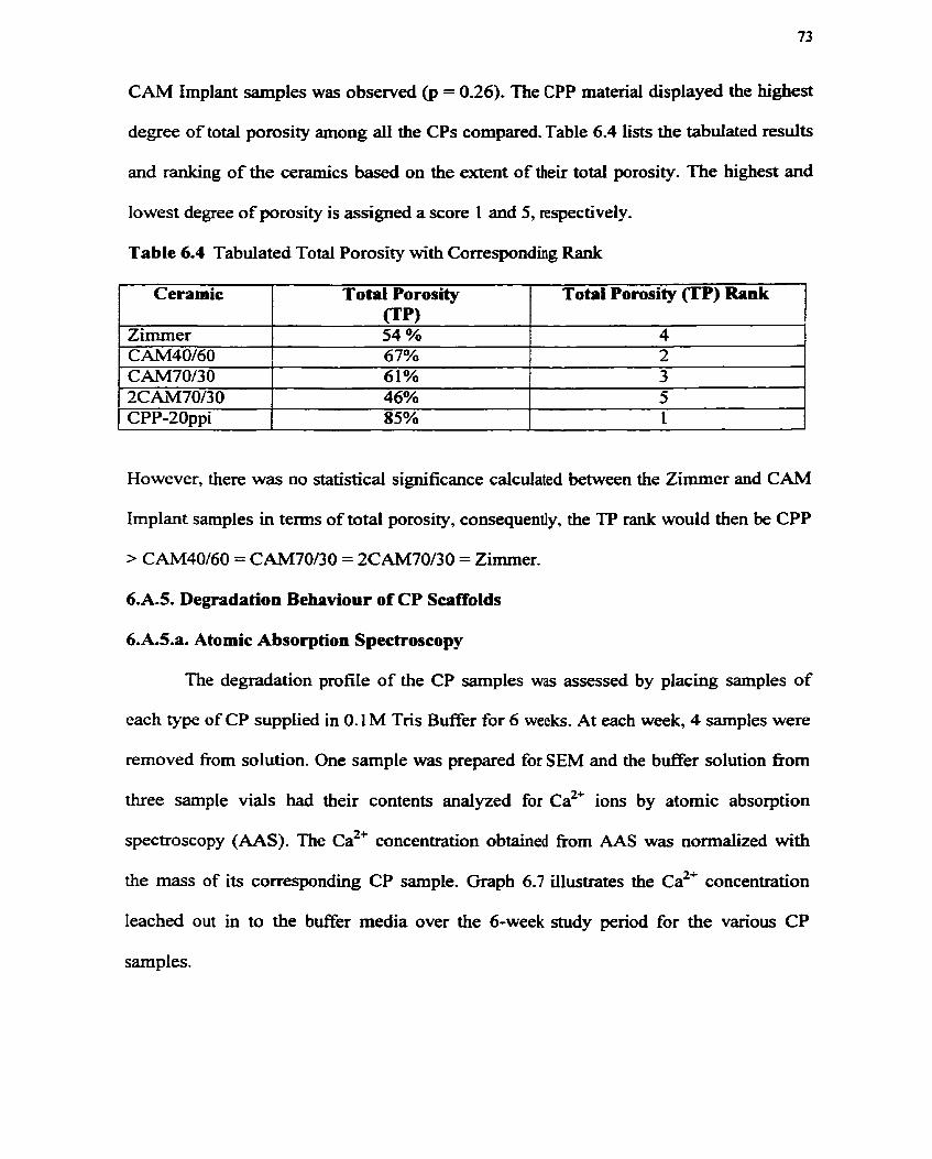
CAM Implant samples was observed @ = 0.26). The CPP material displayed the highest
degree of total porosity among all the CPs compared. Table 6.4 lists the tabulated results
and ranking of the ceramics based on the extent of their total porosity. The highest and
lowest degree of porosity is assigned a score 1 and 5, respectively.
Table 6.4 Tabulated Total Porosity with Corresponding Rank
However, there was no statistical significance calculated between the Zimmer and CAM
Ceramic
ZUnmer C AM40/60 CAM70/3 O 2CAV70/30 CPP-20ppi
Implant samples in terms of total porosity, consequently, the TP rank wouid then be CPP
> CAM40/60 = CAM70/30 = 2CAM70/3O = Zimmer.
Total Porosity f lP ) 54 % 67% 61% 46% 85%
6.A.5. Degradation Behaviour of CP Scaffolds
Total Porosity (TP) b n k
4 2 3 5 1
6.A.S.a. Atomic Absorption Spectroscopy
The degradation profile of the CP samples was assessed by placing samples of
each type of CP supplied in O. 1 M Tris B d e r for 6 weeks. At each week, 4 samples were
rernoved fiom solution. One sample was prepared for SEM and the buffer solution fiom
three sample vials had their contents analyzed for ca2+ ions by atornic absorption
spectroscopy ( AAS). The ca2' concentration obtained fkom AAS was normalized with
the mass of its correspondhg CP sample. Graph 6.7 illustrates the ca2' concentration
leached out in to the buffer media over the 6-week study penod for the various CP
samples.

1 2 3 4 5 6 Time [w k]
Graph 3. Calcium [ca27 ions leached fiom CP samples incubated in 0.1 M Tris bufEer (pH 7.4) for 6 weeks. Atomic absorption spectroscopy was used to calculate the calcium ion concentration in the b a e r soluîion. The calcium ion concentration calculated was norrnaiized with the mass of the CP sample. The results show a variation in ca2+ leaching for the various CP samples over the 6-week study period The bars correspond to standard deviation.
One-way ANOVA was performed between samples and within sample types at each
week and over the entire study period Statistical significance was observed between
samples using one-way ANOVA. However, a t-test was perfonned to determine
statïstical sisnificance between all combinations involving two sample populations at
each tirne. Table 8 ranks the degradation behaviour (refîected by the amount of ca2+ ion
leaching) of each material compared with the other CP matexials at each week based on

Ta b k 6.5 Degradation Behaviour in O. 1 M Tris B a e r (pH 7.4)
3 1 Zimmer > CAM70/30 > 2CAM70130 > CAM40/60 > CPP 4 1 2CAM70/30 > CAM70/30 (= CAM40160) > Zimmer (= CAM40/60) > CPP (=
Weeks 1 2
Ranking Based on StatWtical Signiticance Zirnrner > CAM7OMO > CAM40/60 = 2CAM70/30 2 CPP * CAM70/30 = Zimrner > CAM40/60 = 2CAM70/30
There was statistical significance (p c 0.05) observeci in cafcium ion Ieaching over the
I
5 6
entire study period for CAM70/30, 2CAM70/30, Zimmer and CPP; however, no
CAM40/60) Zimmer > CAM40/60 = CAM70130 = 2CAM70/30 Zimmer > 2CAM70130 > CAM40160 > CAM70/30 > CPP
significance was observed for CAM40/60.
The symbol " 2 " is used to show that 2CAM70/30 = CPP but CAMW60 > CPP
The pH of the b e e r media was monitored over the 6-week study period Graph
6.8 shows the changed in pH of the 0.1M Tris Buffer solution as a bction of time for
the various CP materials.
Time [wk]
pZimmer
C A M40160
a CA M70130
p 2 C A M70/30
CPP-20ppi
Control
Graph 6.8 Change in 0.1 M Tris bufFer pH during the 6-week degradation study p e n d At each, the pH of the bufEer solution containhg a CP m p l e was measured using a pH meter. Standard deviations were calculateci and are represented by an error bar.

There was statistical significance (p c 0.05) observed over the entire study period for
each sample type- There was a &op in pH from the control pH at 1 week that was
statistically significant @ < 0.05). This was observed in ail CP samples. However,
observing the pH trends of the CAM Implant and Zimmer samples over the study period,
it appeared that there was a slow nse in pH up to 5 weeks, but this was followed by a
slight decrease at 6 weeks. The CPP sarnpîes showed a fluctuation on pH up to 4 weeks
but at 5 weeks there was a significant rise in pH that was maintained at 6 weeks-
6.A.S.b. SEM of Calcium Phosphate Surfaces during Degradation Shidy
In addition to caicuiating the calcium ion concentration in the b d e r media over
the entire study period, representative CP samples at 1, 4 and 6 weeks were prepared for
SEM. Figures 6.19 - 6.23 are micrographs that represent the various CP samples at these
time points. The micrographs of the Zimrner material reveaied similar surface
morphologies at 1, 4 and 6 weeks. However, there was considerably more debris
scattered on the surface as denoted by white particdate matter seen at 4 and 6 weeks than
at 1 week. Apparent at 1 week, but more clearly visualized at 6 weeks, was the presence
of large block-like structures embedded within the swface of the material that were
surrounded by smaller irregularly shaped grains. The micropores appeared to be larger
than those seen at 1 and 4 weeks, suggesting that the material was dissolving during the
study penod. The dissolution of the irregularly shaped CP grains allowed the exposure of
another CP grain structure comprising the Zimrner material. Based on SEM images
generated fiom the Zimmer material published in literature (Dziedic et al., 1996), the
smaller ùregularly shaped grains are indicative of the TCP phase and the larger block-
like siruchires depict the HA phase.

The individual grains that comprise the CAM40/60 were observed to have
changed morphologically over the time points studied (Figures 6.2OA - L). Observing the
surface of the sample at 1 week, the individual grains appeared spherical. They were no
longer smooth as they appeared prior to incubation (Figures 6.9A -D), but rather the
sphencal shape was maintained by the organization of thin leaflet structures (Figure
6.20C). At higher magnification (Figure 6.20D), there appeared to be a deposition of
irregularly shaped white structures between the leafïetç. The calcium phosphate grains
within the surface pore volume appeared more sphencal in shape and had a smoother
surface (Figure 6.20B). This smooth area was surrounded by thin leaflet structures
sirnilar to those comprising the surface grains. At 4 weeks, there was little evidence of
leaflet structures on the surface of the material or within the pore volume. The grains still
remained sphencal in shape (Figures 6.20E). However, at higher magnifïcaîion, there
appeared to be white particdate matter covering the surface of the individual grains
resulting in a rougher surface appearaace (Figure 6.20F and H). At 6 weeks, a
distribution in grain sizes was observed with the largest and smallest grains measuring
approxirnately 15 and 2 Pm, respectively (Figure 6.201). Again, the spherical grain
structure was maintained and there was little evidence of thin leafiet structures
surrounding single grains.
The morphology of the individual grains of the CAM70/3 0 samples observed at 1,
4 and 6 weeks had changed over the degradation study period. At 1 week, the grains were
sphencal and smooth but at 4 weeks the grains were no longer smooth (Figures 6.21B
and E). The exposed surface of the single grain cornprised thin leatlet structures that
appeared to extend out fiom the bulk of the grain. The sphencal morphology of the grains

was longer evident at 6 weeks (Figures 6.2 1G) but rather the grains were surrounded with
thin leaflet structures and had their surfaces scattered with white particdate matter
(Figures 6.21B and C).
The 2CAM70/30 grain structures showed complete morphologicai change during
the degradation study pend, as observed at 1 ,4 and 6 weeks (Figures 6-22A - I). The
entire surface of the material constituted thin leaflet structures that appeared to introduce
another level of microporosity than that observed in the as-received scaffolds (Figure
6.9M - P). At 1 and 4 weeks, the spherical shape of the grains was still apparent.
However, this shape was no longer seen at 6 weeks (Figures 6.22H). The surface of the
material had a perforated appearance at this t h e point. At higher magnïkïcation, there
appeared to be a deposition of small globular-like matter on the exposed surfaces in the
structures compnsing the material (Figure 6.221).
There was no apparent morphological change in the CPP grain structures at 1, 4
and 6 weeks (Figures 6.23A - 1). The grains appeared similar to those obsewed of the as-
received material throughout the study period.

Figures 6.19A - L. Scanning electron micrographs of Zimmer samples incubated in 0.1 M Tris b a e r . Micrographs A - Dy E - H, 1 - L show increasing maenification of the surface of the Zimmer samples exposed to the buî€er solution at 1, 4, and 6 weeks, respectively. The erosion of the surface due to degradation has aiiowed the exposure of larger grains seen at 1-week (B) but more clearly evident at 6 weeks (0. The precipitation of white particdate matter on the surface of the sample was evident by 4 weeks (G) but more diamatically seen at 6 weeks (I and J). It would appear that the srnalier grains cornprishg the material had dissolved as seen by the increase in microporosity nom 1 @) to 6 weeks &). . F.W. = 90 p, 18 pm, 9 pn and 9 pm for A, By C and D, respectively. F. W. = 90 pm, 18 pm, 9 pn and 9 p for Ey F, G and & respectively. F.W. = 18 pu, 18 p, 9 pn and 9 pm for 1, Jy K and L, respectivefy.

Figures 6.20A - L. Scanning elextron micrographs of CAM40/60 samples incubated in 0.1 M Tris buffer. Micrographs A - D, E - H, 1 - L show increasing magnincation of the surface of the CAM40/60 samples exposed to the buffet solution at 1, 4, and 6 weeks, respectively. The change in individual grain structure over 1, 4 and 6 weeks is clearly seen in micrographs C, G, K. The prestnce of microcrystals, seen as white particdate matter, was first seen at 1 week @). By 6 weeks, there was an increase in the prevalence of thin leaflet structures surrounding individual grains, as seen in L. F.W. = 90 Pm, 18 p, 22.5 p and 6 pm for A, By C and D, respectively. F.W. = 90 pm, 18 pm, 9 pn and 6 p for E, F, G and H, respectively. F. W. = 90 pn, 36 p, 18 Cm and 18 pm for 1, J, K and L, respectively.

Figures 6.21A - 1. Scsinning electron micrographs of CAM70/30 samples incubated in 0.1M Tris bufEer. Micrographs A - C, D - F, G - 1 show increasing magnification of the surface of the CAM70/30 sample exposed to the b a e r solution at 1, 4, and 6 weeks, respectively. The change in grain morphology was clearly seen over the study period, as denoted in micrographs C,F, and 1. The smooth rounded appearance, seen at 1 week, has become roughened by the appearance of thin leafkt structures situated verticaily on the surface of individual grains (F) and surrouuding the grains, seen at 6 weeks. F.W. = 90 p, 18 pm, and 9 pm for A, B, and C, respectively. F. W. = 90 p, 18 pm, and 9 pm D, E, and F, respectively. F.W. = 90 pn, 36 pm, and 18 pm for G, H and 1, respectively.

Figures 6.22A - 1. Scaoning electron micrographs of 2CAM7OB0 samples incubated in 0.1M Tris buffer. Micrographs A - C, D - F, G - 1 show increasing maguification of the surface of the 2CAM70/30 samples exposed to the b d e r solution at 1, 4, and 6 weeks, respectively. At 1 week, the individual grains comprising the 2CAM70/30 sample have completely undergone morphological change compared to the as-received grain structure (Figures 13M -P). The individual grains are seen to be fomed of staggered thin leaftlet plates (A-C) that dimish in thiclcness and prevelance by 6 weeks (H and Z). The appearance of white particdate matter within the microporosity of the matenal is clearly seen at 6 weeks o. F.W. = 90 p, 36 p, and 18 pm for A, B. and C, respectively. F.W. =90 p, 18 un, and9 pm D, E, andF, respectively. F.W. = 90 p, 18 p, and9 pm for G, H and 1, respectively.

Figures 6.23A - 1. Scanning electron micrograpbs of CPP-20ppi samples incubated in 0.1 M Tris bufKer. Mifrographs A - C, D - F, G - 1 show increasing rnagnification of the surface of the CPP-2Oppi samples exposed to the buffer solution at 1, 4, and 6 weeks, respectively. It is evident nom micrographs A, D, G, that there is no significant change in microporosity and individuai grain size, as seen in B, E and H. The white particdate matter observed on the d a c e of a grain, seen in E, are an aaifacts of critical point drying. F.W. = 90 pm, 18 pm, and 9 Fm for A, B, and C, respectively. F.W. = 90 p, 18 p, and 6 pm D, E, and F, respectively. F.W. = 90 p, 18 CM, and 6 pm for G, H and 1, respectively.

6.B. Static In Vitro Studies
6.B.1. CeU Culture Substrate for Cell Seeding and Colonization
It was necessary to determine an appropriate substrate onto which a 3-
dimensionai material could be placed in order to seed cells. The appropriate substrate
would be one that would maximize ceii colonization on the 3-D matenal. Two substrates
were used in this expriment: 1) tissue culture treated (TCT) and 2) bacteriological-grade
(BG) 24-we11 plates. Representative samples of each type of calcium phosphate supplied
(Zimmer, CAM40/60 and CPP-20ppi) were placed onto TCT and BG substrates and
seeded with BMDC for 2 weeks. BMDC were also seeded directly on to TCT and BG
substrates to serve as positive and negative control, respectively. After 2 weeks, TCT and
BG surfaces as well as the bottom face of the ceramic (the surface in direct contact with
the two substrates) were analyzed by SEM. The activity of the BMDC seeded duectly
ont0 K T and BG substrates is clearly seen in Figures 6.24A-B and 6.25A - B,
respectively. Figure 6.24A shows evidence of globular-like structures, indicative of
cernent line matrix, which appears to cover the surface of the TCT substrate. At higher
magnification (Figure 6.24B), collagen bundles were seen to lie over top this globular-
like surface and become encrusted with irregularly shaped crystal-like structures
indicative of calcium phosphate crystals. in contrast, Figure 6.25A shows the state of the
BMDC population grown on BG for 2 weeks. Irregularly shaped structures were seen
colonizing the BG surface. These structures are likely the remnants of dead cellular
matter that have failed to spread on this substrate.

The surface in direct contact with the TCT and BG substrates was analyzed to
assess the viability of the ceLi population grown at this interface. Figures 6.24C -F and
6.25C - F show the morphologieal appearance of the cells colonizing this sudace.

Figures 6.24A - F. Scanning electron micrographs of ce11 colonization and activity on 3- D porous cetarnics cultured in TCT 24-well plates. Passaged rat bone marrow cells were seeded on to 3-D porous substrates and cultured for 2 weeks in TCT 24-well plates. RBM cells were seeded directly on to TCT weUs to serve as positive controls. Figure A shows a ce11 layer pulled away after processing exposing globular-like accretions that appear to make direct contact with the TCT substrate. At higher magnifïcation, Figure B, mineralized collagen was seen encrusted into this globular-like layer. Figure C shows the 3-D porous surface that was in direct contact with TCT surface for 2 weeks. At this magnification, it appears that there is minimai cell colonization on this surface and at higher magnification, Figure D, the cells appear necrotic. Loose comective tissue that does nct appear mineralized was seen colonizing this surface. Figure E shows calcium phosphate particles, located away fiom the bulk sample. encrusted with mineralized collagen (Figure F). Such particles are LikeIy the result of the degrading calcium phosphate block sample. F.W- = 60 Fm, 18 p, 450 p, 60 Pm, 60 mm and 1 1.4 prn for A, B, C, D, E and F.


Figures 6.25A -F . Scanning electron micrographs of ce11 colonization and activity on 3- D porous ceramics cultured in BG 24-well plates. Figures A and B reveal the state of the ce11 population cultured directly on to the BG substrate at low and tugh magnifications, respectively. M e r 2 weeks, the cells appeared rounded and very few were seen spreading on the BG surface. Figure C shows the underside of a 3-D porous ceramic that was in contact with the BG surface for 2 weeks. Very few cells were observed on this surface and loose connective tissue was seen colonizing this surface. Figure D shows a calcium phosphate hgment that has become loose fiom the buik sample. There was no evidence of cellular colonizattion or collagen mineralization on or around this particle. Figure E illustrates the BG surface that was in contact with a CPP sample. Again, there was no evidence of cellular colonization or activity in this area. However, Figure F shows the surfàce of the CPP that was in direct contact with the BG surface during the 2-week culture period. There was evidence of cellular colonization and activity throughout the porous structure. Cellular matter appeared to be deposited in to the micropores of the sample with ce11 sheets over-laying the surface grains. F.W. = 180 Pm, 45 pm, 600 Pm, 150 Fm, 0.9 mmand45 pnfor A, B, C, D, EandF.


6.B.2. Optimum Ce11 Seeding T h e
The appropriate ce11 seeding time was detemiined by counthg the total number of
cells adhering to TCT nibstrate as a function of time. Graph 6.9 iilustrates the total
amount of adherent and non-adherent cells counted at 0.5, 1,3 and 4 hours.
& --- --- - ---- - ---------
0 -5 1 3 4 Time [hi]
O NAC
W'C --
Graph 6.9 Total celi attachent to TCT (tissue culture treated) plastic as a function of time. Passaged rat bone marrow cells were seeded on to TCT 24-well plates for 0.5, 1, 3 and 4 hours. At each time point, 0.01% trypsin was used to remove the adherent cells from the substrate surface. A Coulter counter was used to count the total ce11 number correspondhg to the adherent cells (AC) and non-adherent cells (NAC). The bars represent standard deviation.
It is evident with increasing t h e that the amount of adherent cells counted increased
while the non-adherent cells counted decreased. These results suggest that the minimal
acceptable ce11 seeding time on TCT is 1 hour. Consequently, seeding passaged RBMD
ceils for 1 hour was considered the optimum ce11 seeding time for funw experiments.

6.B3.CeU Adherence & Colonization on 3 4 CPs during CeU Seeding
To study the capacity of cells to adhere and colonize 3-D calcium phosphate
substrates during the 1 hour ce11 seeding period, the total number of cells adhering to the
CP surface, to the well-plate (bacteriological grade) and suspended in ce11 culture media
were counted. Three different CP substrates were used (Zimmer, CAM40/60 and CPP-
2Oppi) as well as negative (BG) and positive (TCT) control substrates. The results of the
cell attachment assay are presented in Graph 6.10.
- - - - --
- NAC
m*C Weil-plate
Graph 6.10 Total ceil attachent to various substrates after t hour. NAC, AC and Well- plate columns represent the total ce11 number counted via a Coulter counter in the cdhue media, attached to the substrate and well-plate, respectively, after 1 hour of ce11 seeding. TCT plastic and BG (bacteriological grade treated plastic) was used as positive and negative controls, respectively. The error bars correspond to the calculated standard deviation.
To assess the success of the trypsinization procedure, a sample of each CP type,
after trypsinization, was stained with toludine blue. Figures 6.26A-D are light

photographs showing the various surfaces o f the CP stained with TB. At higher
magnifications, obtained by SEM, the presence of cellular debris remaining after
trypsinization was clearly visualized on the various CP substrates (Figures 6.27A - F). These observations suggest that the trypsinization procedure used in the cell attachment
assay was not a reliable method of quantirjting ce11 attachment to CP substrates.

Figures 6.26A - D. Colour light photographs showing the various surf's of the CAM40/60 and Zimmer samples stauied with toluidine blue afler trypsinktion. Figures A and B show the surfaces of the CAM40/60 and Zimmer, respectively, that were seeded with cells for 1 hour, trypsinized for 45 minutes and then stained with toluidine blue. A blue-violet colour was seen on this ceii seeding surface, with an increase in colour intensity seen within the pore volume. Figure C shows the fracture surface of the CAM40/60 sample and Figure D shows the surface opposite the ce11 seeding surface of the Zimmer sample. There was no evidence of cellular penetration within the bulk of the CP samples or cell colonization of the surface opposite the seeding surface, as denoted by the lack of blue-violet staining seen in Figure D. Photographs A, B, C and D have field widths = 23 mm.

Figures 6.27A - F. Scaoniag electron micmgraphs showing the Zimmer, CPP and CAM40/60 surfaces pst-trypsinizttion. Figures A - B, C - D, and E - F show increasing magniûcations of the Zimmer, CPP and CAM40/60 d a c e s after trypsinktion, respectively. At low magnifïcation, there was evidence of cellular matter stiil present on the surfàce of the various CP substrates and at a higher magnïfication, whole cells were seen invaginating the microporosity of the surface 0. F.W. = 180 p, 36 pm, 600 p, 45 p, 180 pm and 22.5 pm for A, B, C, D, E and F.

To assess the extent of colonization on the 3-D CP substrates at 1 hour,
representative samples of each CP type were prepared for SEM. The morphological
appearance of the cells colonizing a representative CP substrate (CAM40/60) is seen in
Figures 6.28A - D. Most of the cells present on the various calcium phosphate d a c e s
appeared as round cells extending short microspikes and larnellipodia. The seeding
surface appeared to be compietely covered with these cells making it difficult to observe
the underlying substraa

Figures 6.28A - D. Scanning electron micrographs of cell colonhtion on 3-D porous ceramics after 1 hour of ceil seeding. Figures 34A - D are micrographs of increasing m a ~ c a t i o n s showing the morphology of the cells colonizing the surface of a CAM40/60 seeding s h c e . Simila. observations were seen on the Zimmer, CAM70/30, 2CAM70/30 and CPP surfaces. Field widths = 300 pn, 300 pm, 45 p and 18 p for A, B, C and D, respectively.

6-B.4- Dexamethasone (O) Culfures
Calcium phosphate samples mauitaiaed in the absence of DEX for 7 days did net
display signs of osteogenic activity in the fom of mineralized bone tissue. This
observation is consistent with previous reports on the rat bone marrow system, which
state the requirement of DEX in the culture media for osteoprogenitor dinerentiation and
matrix synthesis. After 1 week in DEX (-) culture conditions, the surfaces of each porous
CP type were investigated for signs of osteoclastic resportion. Evident by SEM
observation of the Zimmer material (Figure 6.29A - D) was the presence of large
aggregate cells with round morphologies. At higher ma@cation (Figure 6.29C),
irregular shallow erosions on the calcium phosphate surface in the vicinity of these cens
was suggestive of resorption. The size of the resorption lacunae was measured to be
about 10 - 30 Pm. Most pits were round having scalloped borders, but multilobular pits
were occasionally observed. The cells occupying these pits appeared to have a rough
surface morphology (Figure 6.29D) perhaps indicative of muitinuclearity and/or the
intemalization of calcium phosphate particles. It is inconclusive; however, whether these
cells are osteoclasts resorbing the calcium phosphate surface. Consequently, the
micrographs merely suggest that these cells are osteoclast-like cells. A positive TRAP
(Tartrate Resistant Acid Phosphatase) activity wouid aid in contiming the multinuclear
phenotype of osteoclasts but was not conducted as part of this project.
The CAM Implant and CPP ceramics did not show evidence of active resorption
of their surfaces by giant multinuclear cells a d o r osteoclast-like cells. Instead their
surfaces were covered with thin ce11 sheets that appeared fibroblastic in nature (Figures
6.29E, 1, M and R). These fibroblastic-like cells were spread out over the entire surface

area exposed and made contact with the calcium phosphate grains through inserthg their
pseudopodia înto the microporsity of the materid (Figures 6.29F, J, O and T).
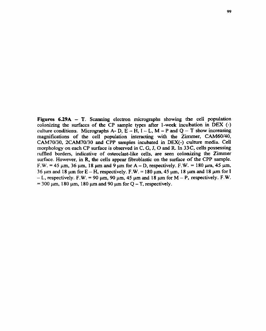
Figures 639A - T. Scanning electron rnicrographs showing the celi population coloninng the surfaces of the CP sample types d e r 1-week incubation in DEX (-) culture conditions. Micrographs A- D, E - H, 1 - L, M - P and Q - T show increashg magnifications of the ceil population interacting with the Zimmer, CAM60/40, CAM70/30, 2CAM70/30 and CPP samples incubated in DEX(-) culture media Ceil morphology on each CP d a c e is observed in C. G, J, O and R. In 33C, celis possesshg d e d borders? indicative of osteoclast-like cells, are seen colonizing the Zimmer surface. However, in R, the ceils appear fibroblastic on the surface of the CPP sample. F. W. = 45 pn, 36 Pm, 18 pm and 9 pm for A - D, respectively. F. W. = 180 pm, 45 q, 36 p m and 18 Fm for E - H, respectively. F.W. = 180 Pm, 45 pm, 18 Pm and 18 pm for I - L, respectively. F-W. = 90 pm, 90 Fm, 45 pm and 18 pn for M - P, respectively. F-W. = 300 Pm, 180 Fm, 180 pm and 90 pm for Q - T, respectively.


6.C. CeU Colonization, Arrangement and Function in Static & Dynamic Culture Systems as a fùnction of Tirne
6.C.l. SEM Observations in the Static Culture Environment
The CP samples at 4 hours, 2 days and at 1 - 6 weeks were observed by SEM to
shidy ce11 colonization, arrangement and activity throughout the macroporosity
characteristic of each sample type. Observing the seeding surface of the Zimmer and
CAM Implant samples after 4 hours of incubation at 37"C, 95% air and 5% CO2, the
osteogenic cells with plump rounded morphology appeared to colonize the entire surface
area (Figure 6.30A - D). These cells invaded even shallow surface pores. At the edge of
the samples, the cells appeared to be more flat and migratory as hdicated by extending
pseudopodia. The migration of the cells appeared to be facilitated by the anchoring of
their pseudopodia to the substrats (Figure 6.30C). After 2 days, the osteogenic cells
assumed a more elongated, fibroblastic-like morphology (Figure 6.30K). At 2 days, the
fkst sign of ce11 bridging pores was observed. Figure 6.3 1A shows an extending ce1
process bridging an approximately 170 p m pore and Figure 6-3 1 C illustrates an entire
ce11 body bndging an approximately 100 prn pore opening with its cell processes making
contact with the periphery of the pore volume (Figure 6.3 ID). It was apparent at this
early stage in the ce11 culture that the osteogenic cell population had colonized the
calcium phosphate surface and had become migratory after 4 hours. However, there was
no evidence of early bone formation events (Le. deposition of cernent line by osteoblasts)
at these early t h e points. These observations were consistently seen on dl CP matenals.

Figures 6-A - L. Scanning eltctton micrographs of ce1 colonization, migration and activity on 3-D porous ceramics at 4 hours and 2 days. Passageci RBM celis were seeding on 3-D porous substrates for 4 h and 2 days in static cuItutiag environments. Figures A - D and 1 - L are micrograp6s of increasing maglllfication showing the morphology of ~e celi population at 4 h and 2 days, rrspectively. Figures E - H are micrographs of inmeashg maguifïcatio~ls illustrating the morphology of the ccIls colonizing a 3-D porous substrate a f k 4 houn of dynamic culturing. The morphology of the cells coloniang the same 3-D porous subsûate cultuceci in static and dynamic environments a . 4 hours appeared similar. After 4 hours the celis appcated migratory as indicaîed by their extcnding pseuQpodia (Figure B). A&er 2 days, the cclls have s p d over the entire sading surEace and have migrateci to the edge of the sample (Figure 1 and K). Extending micmspikes and lamciüpodias wexe observed at 2 days (Figure L). F.W. = 600 p. 45 p. 45 pm and 45 pn for A - D, rrspctively. F.W. = 600 pm, 300 pm, 180 pm and 60 fot E - H, rcspcctÏvely. F.W. = 450 CL^, 90 pm, 90 pm and 36 pm for I - L, respectiveiy.

Figures 631A - D. S d g elcctmn mictograpbs of c d bridging at 2 days. Figure A shows a ceii ptocess extending over a pore opehg of appmrimately 170 p after 2 days of ceii culture. At higher maoiiflcation, Figure C, it was evident that the ceii process was extending h m a singie ce11 body. Figures C and D show a whole c d extending over a 100 pm pore opening a f i 2 days at low a d higber magnifhtions, rcspectively. F. W. = 290 un, 1 10 pan, 290 pm and 58 pn for A - D, respectivee1y.

Examining the surface of the Zimmer and CAM Implant samples at I week, it
was apparent that the rnajonty of the surface pores became occluded with ceU bridging
the pore openings, as observed by SEM. The cells covering the pores had interacted to
form a thin sheet that appeared to spiral around the pore volume resulting in its complete
coverage, as seen in Figure 6.32C. After 6 weeks, the surface of the material had become
completely covered with multi-layered ce11 sheets (Figure 6.32D). Observing the fieeze-
fractured surface of the samples at 6 weeks (Figure 6.32E - H), it was apparent that the
ceil sheets surrounded the entire exposed surface area with no evidence of cellular
penetration and colonization within the bulk of the sarnple. At higher mapification
(Figures 6.32F), pore bndging of almost d l the surface pores by ce11 sheets was
visualized. However, there was evidence of loose comective tissue present within the
pore volume but bone tissue formation was not observed. These observations were
consistently observed in the Zimmer and CAM Implant ceramics at al1 the time points
studied. In contras& the CPP-45ppi, 20ppi and IOppi scafliolds, after 1 week in DEX (+)
culture, had ce11 layers covering their entire porous structure that followed the contour of
the pore openings with no evidence of pore bridging (Figures 6.3 3 A - C). Occluded pores
(Figure 6.33D), however, were observed in Mly intercomected CPP samples of a
smaller pore size range (1 50-200 pm)-

Figures 632A - L. Scaaoing electron micrographs of the colonization of cells on 3-D porous substrates after 6 weeks. Figures A - H are micrographs illustrating the colonization of celis on 3-D porous cetamics cultured in a static environment- Figure A shows the typical Zimmer a d o r CAM ImpIant porous surface that was seeded with RBM cells. After 1 week in DEX (+) culture conditions, ce11 sheets were seen overiaying these surface pores (Figure B) and at higher magnification, Figure C, it is apparent that ce11 sheets are spiraling over the pore volume resulting it its complete occlusion. At 6 weeks, the entire surface area was covered with multi-layered ce11 sheets (Figure D) and the surface pore openings were no longer visible. Figure E shows a fieeze-fractured surface of a typical CAM implant sample cultured with RBM cells d e r 6 weeks. At this magnification, it was evident that ce11 sheets bad fomed dong the surface area of the block sampte but not any evidence of cellular activity was seen within the bulk material. Evidence of pore bridging was seen over a pore opening measuring 150 pm (Figure F). However, some surface pores contained in their pore volume loose comective tissue that are overlaid with ce11 sheets (Figure G), but at higher magnification, there was no evidence of cement line formation or mineralized collagen (Figure H). M e r 6 weeks in the dynamic culture environment, ce11 sheets had also grown over surface pore openings and followed the contour of the block cerarnic sample (Figure 1). However, where intemal pores were seen connected to surface pores, there was evidence of loose connective tissue colonking the pore volume (Figure J and K). At higher rnagnincation, Figure L, it is apparent that the deposition of the loose connective tissue was made possible by the intercomecting channels between pores. F.W. = 2.25 mm, 2.25 mm, 693 Fm and 2.25 p m for A - D, respectively. F.W. = 2.58 mm, 0.9 mm, 528 p m and 60 p for E - H, respectively. F.W. = 360 pm, 1.00 mm, 1.30 mm and 450 pm for 1 - L, respectively.


Figures 6.33A - D. ScaMing electron micrographs of CPP samples cuitured in DEX (+) static culture conditions at 1 week. Figures A, B and C show the colonization of celis dong the entire porous network of the CPP-lûppi, CPP-2Oppi and CPP-45ppi samples, respectively. In Figure D, there îs evidence of cell bridging over fbily htercomected pore openings having nominal diameters measuring 150 p. F.W. = 2.32 mm, 1.74 mm, 1.74 mm and 2.8 mm for A - D, respectively.

On examining various portions of the fieeze-fiactured surfaces, it is evident that
d l calcium phosphate sarnples supported bone tissue formation. The evidence of cernent
line formation, coiiagen miwralization and morphologicaily distinguishable bone tissue
observed on the entire CP substrats demonstrates this. Figure 6.34A shows an elongated,
fibroblast-like osteoblast lying over mineraüzed collagen bundles on the Zimmer
subsate (also observed on the CAM Implant and CPP samples). While on the same
sarnple surface, an osteocyte is seen lying in its fonning lacuna (Figure 6.34B). The
centre of the fkeeze-hctured surface showed no evidence of biological matter (Figure
6.34C) rather the HA and TCP grallis that comprise the materiai were cleariy
distinguishable.

Figure 6.34A-C. Figure A shows a scanning electron micropph of an osteoblast migrating over minetalized coilagen colonizing the calcium phosphate substrats of the Zimmer material at 1 week (F.W. = 44 p). Figure B shows a scanning electron micrograph showing an osteocyte embedding itself in its newly forming l a c m after 2 weeks (F.W. = 12.8 p). Figure C shows a scannuig electron micrograph showing the central area of the fieeze-fracturai surface of the Zimmer material after 2 weeks in static culture conditions. At this magnincation, only the grains that comprise the materiai are seen with no evidence of biologicai matter in the vicinity (F. W. = 29.7 p).

The different CAM Implants ceramics studied showed similar biologicai profïie.
An amorphous layer, measuring approximately 0.5 pm, covered the exposed spherical
grains comprising the CAM Implant materials. This layer was deposited dong the
contour of the grain structures as well as on the thin leaflet structures surroundhg the
sphencal grains, as seen in Figures 6.35A and B. At 6 weeks, morphologically
distinguishable bone tissue was seen only on the exposed surface of the material, above
the pore volume and never seen within the pore volume or in the bulk of the material
(Figure 6.36A).
Figure 6.37 represents the appearance of the CPP scaEold after 2 weeks cuitwe in
the presence of RBMD cells. These cells populated the outer and inner surfaces of the 3-
D scaffold and formed a continuous sheet following the surface contour of the scaffold as
seen in Figure 6.37A. Figures 6.37B, C and D provide higher magnifications of scanning
electron micrographs of the matrix laid down within the scafTold. Figure 37B
demonstrates mineralized collagen fibres bridging between individual grains of the CPP
scaffold. At this magnification the collagen would seem to be inserting into the
microcrystalline surface layer of the CPP grain structure, which is more clearly visuaiized
in Figure 6.37C as a surface layer which is quite distinct fiom the underlying CPP
surface. Ce11 processes aiso adhered to this surface layer, as shown in Figure 6.37D,
which enveloped the grain structure of the underlying surface. These results were
consistent with al1 macroporous CPP types studied.
6.C.2. SEM Observations in the Dynamic Culture Environment
After 6 weeks in the dynamic cell culture system employed, the surface pore
volumes of fieeae-fiactured Zirnmer and CAM implant samples showed more evidence

of cellular matter and morphologicaily distiaguishable bone tissue (Figures 6.36C) that
than that observed in the static environment. Some surface pores were occluded with
overlying ce11 sheets, as observed in the static culture environment. However, the ianer
surface of the pores were lined with an afiibillar layer u p n whïch collagen bundies were
mineralized (Figures 6.35C). Densely packed mineralized tissue, characteristic of bone
tissue occupied the remainder of the pore volume. This new bone tissue appeared to make
intirnate contact with the calcium phosphate grains, as shown in Figure 6.35D.

Figures 6.35A- D. Cernent üne formation in static and dynamic culture enviroments. Figures A and D are scanning electron micrographs of fkeeze-fkactured surfaces of the CAM40/60 sample cultured in DEX(+) static and dynamic environments d e r 6 weeks, respectively. There was evidence, at this magnincation, of cernent h e formation that appeared to be deposited dong the surface of the grains. After 6 weeks of static culturing, an amorphous-lüre layer was seen covering the surface of the grain structures and had been deposited within the spaces between individual grains (Figure B). Figure D shows densely packed bone matrix that had formed d e r 6 weeks of dynamic culturing that appeared to make intimate contact with the grain structure. F.W. = 6.5 pm for A - D, respectively.

Figures 636A - D. Scannuig electron micrographs showing the extent of bone matrix elabmation on 3-D porous ceramics cuitured in static and dyoamic environments. Figures A and C depict keze-fkactured surfaces of 3-D porous ceraxnics showing morphological distinguishable bone grown in static and dynamic culture conditions, respectively. The bone ma& depicted in Figure A had grown over a surface pore opening while the bone forrned in Figure 42C had grown within îhe pore volume of a surface pore. Figures B and D show evidence of mineralized collagen colonizing the surface of the calcium phosphate grains. F.W. = 43 pn, 13 pu, 43 p and 20 pn for A - D, respectively.

Figure 6.37A - D. Scanning electron micrographs showing the appearance of the CPP scaffold cultuced in the presence of rat bone marrow celis for 2 weeks. F.W. = 178 ~ i m , 6 p, 2 pm, 3.4 pm for A, B, C and D, respectively-

6.C.3. LM of CeU Colonization and Arrangement in Static & Dynamk Cuhre Systems
Senal histological sections were cut according to the method described previously
of the CP porous samples at 1 - 6 weeks and stained with H&E. The samples were seeded
(approximately 1 x 10⁶ total cells) with subcultured RBMD cells and grown D M (+)
culture both in static and dynamic media environments. Figures 6-38A -D are H&E
stained histological sections representing the midpoint (approximately 2 mm into the
sarnple) of ceII-seeded CPs cultured in static and dynamic systems at 6 weeks. The white
areas indicate the ghost of the ceramic after decalcification. However, even after 5 weeks
in decalcimg solution rernnants of calcium phosphate crystals were observed
(tramlucent particdate matter). In particufar, CAM70/3O and CPP sarnples took
approximately 8 weeks to decalcifjr, although some crystals still remained. It is clearly
evident that there was a greater abundance of bone-like tissue (dark pink) covering the
surface of samples cultured in the dynamic environment than in the static environment.
Figures 6.41B shows plump osteoblasts linuig the s d a c e of newly fonned bone that
produced substantially more matrix and bone than that observed on the CPs cultured
statically. There was considerably more mineralized tissue observed within the surface
pore volumes of the Z h e r and CAM Implant samples grown in the dynamic culture
system than in the static system (Figures 6.3912 and B). It is apparent in Figures 6.38C
and 6.38D that there is new bone formation in the intemal pores, htercomecting
channels and the surface of the CPP sarnple both in static and dynamic systems.
However, more bone formation was observed on CPP samples grown in the 3-D rotating
system. The Azan Heidenhain connective tissue stain was used to clearly confirm bone-
like tissue comprishg coilagen (dark blue). The nuclei of cells appeared red as a result of

this stain. Figure 6.42C shows the abundance of bone tissue with embedded osteocytes
laid down within the pore structures of the CPP ceramic cuitured dynamically.
As detennined previously, there is a varying degree of interconnectivity
associated with the CP porous ceramics suppiied. Observing the interior portion of the
Zimmer and CAM Implant samples, it was evident that there was loose comective tissue
occupying the pore volume as denoted by the light pink stain (Figures 6.40A). However,
no bone formation was observed witbin the bulk of these materids. RecaII that the
samples were cut to the midway point and the histological sections presented, are
therefore, representative of this portion of the sample. In cornparison, samples cultured
dynamically showed a greater degree of cellular matter and comective tissue within the
pore volume and, in some areas bone-like tissue were observed (Figures 6.40B).
Examining the cellular activity at 2, 4 and 6 weeks on representative samples of
the Zimmer, CAM Implant and CPP types cultured in static and dynamic environments, it
was evident that the cell-seeded scaffolds incubated in the d y n e system supported
more bone mat& formation than that observed in the static environment at al1 t h e
points. In fact, even after 8 weeks of static culturing, there appeared to be considerably
less matrix deposition dong the surface of the Zimmer and CAM Implant scaffolds than
that observed after 6 weeks of dynamic culturing (Figure 6.43).

Figure 638A-D. Six weeks d e r static and dynamic cell culturing of porous calcium phosphate substnites (HM stain). Figures A and B show the amount of bone matrix elaboratioa (red stain) on the surface of a CAM Implant sample cultured in çtatic and dynamic environments, respectively. Figures C and D show bone r n h elaboration throughout a porous CPP-20ppi sample maintained in static and dynamic culture conditions. White area indicates the ghost of the cerarnic remaining &er decalcification. Figures A, B, C, and D have field widtbs = 683 W.

Figures 639A - B. Extent of pore bridging on 3-D porous ceramic surfaces d e r six weeks of static and dynamic ceil culturing (HE sbin). Figure A (F.W. = 109 pm) shows thin cell layers bridging surface pores (indicaîed with an arrow) having small amounts of bone matrur within the pore volume (static culture), while Figure B (F.W. =
109 pm) shows a higher degree of bone matrix formation within the pore volume of surface pores (dynamic culture). (CAM Implant-type shown here)
Figures 6.40A - B. Lack of osteogenesis within the bulk of the CAM Implant samples (Azan Heidenbain connective tissue stain). Figures A (F.W.= 109 p) and B @.W.= 109 pm) show a histological section representïng the midpoint of the bufk sample cultureci in static and dynamic environments, respectively. Both figures dernonstrate the lack of osteogenesis throughout the entire porous network, as indicated by the lack of staining in the central portion of the sample. Similar observations were seen in the Zimmer samples. White area indicates the ghost of the ceramic d e r decalcification,

'(w =wl) auoq arlr am=!pam pu p e y w =nq3ws aql Aq (qtmpq sir 'aumlorr aiod a q q p \ pqmd Alaspap s? tirq) auoq atp JO a p s atp %uy! uaas 9s a = i q m o %wax ' ( ~ ~ o L z =-MX '3 ngwr sga mq,y pappaqm (UW pi) sa~A30;)3so a q pw ( q s aqq) anssp auoq paqpa- JO aawsad atp smn~rim u y s anssg a+vouum meqnap!aH mzv a u -aaoq pauuoj A ~ M ~ u ay) uqaw pppquua
a- s a W m '(d OLZ = -fi-d .Bis 3 ' 4 ~ ~0 (8) uoge3@em 3a@q iv ' ( sa ldm ~ammz tq riaas osp) saldmas x q d q yw3 JO aumlorr aiod a q u g p uog~mio~ auoq $0 ald->ta p!dh B MOqS ( d n 601 = 'M'J 3 3 H) V !S33ll%d * h ~ ( l @ ~ @ p p m p saidmes a JO samnlon aiod uopmuoj auoa -3 -VI*, sam2hg
3

Figure 6.42A - D. Conhation of bone formation by the Azan Heidenhain comective tissue s t a h Figures A @.W. = 683 pm) and B @.W. = 683 p) show typical examples of bone elaboration on CPP-20ppi and CAM Implant/Zimmer samples cultureci dynamicaily. Figure C (F.W. = 109 pm) reveals that histolgically identifiably bone has fomed throughout the porous CPP sample (blue stain). While in Figure B, bone is formed o d y dong the surface of the CAM Implant and sometimes within the pore volume (Figure D, F.W. = 109 p ). ( A h seen in the Zimmer samples).

Figures 6.43A- D. Extent of bone matrix elaboration on CP scafEolds after 8 weeks of static culturing (H&E). Figure A demonstrates that even after 8 weeks of static culturing there is still less rnatrix laid down on the surface of the CP scaffiolds (Zimmer-typ shown here) than after 6 weeks of dynamic cuitining (Figure B). It wodd appear that there is comparable amount of bone matrix deposition on the s d k e of the CP sdKolds after 4 weeks of dynamic culturing (Figure C) and 8 weeks of static culturing (Figure A). Figure D shows the extent of rnatrix deposition after 4 weeks of static culturing. Boue maaix is shown as a darkened band (indicated with an arrow in A) situateci dong the CF substrate. Fields width for A, B, and D = 0.27 mm.

6.C.4. BSE Imaging
Figure 6.44 shows a montage of backscattered scanning electron images of the
surface of a CAM40/60 sample &er 6 weeks in ceil culture. The white areas represent
the calcium phosphate components, the gray areas depict the embedding resin and the
black areas are the pores not infïltrated with resin. Light gray areas were observed around
the circumference of the sample and sparingly seen in some pore areas. Scannïng electron
rnicroscopy confirmed that these areas were biologicd. Pore bridging by ce11 sheets, also
observed by SEM and LM, were observed along s d a c e pores by BSE imaging. The
cellular behaviour of pore bndging occurred along d a c e pores in both Zimmer and
CAM Implant samples. It was observed that pore bridging occurred over pores of certain
d e r and outer diameters. Consequently, using 12 randomly chosen Zimmer and CAM
Implant samples cultured for 6 weeks with RBDC, the outer and inner diameters of
surface pores that were non-bridged and bridged were tabulated. Surface pore dimensions
were calculated fiom BSE images taken midway through the samples. The relationship
between the outer and inner diameter of a pore (Ofli) provided information about the
potential for that pore to become bndged. In order to interpret the results, two
assumptions were made: 1) ce11 bridging was independent of the CP composition and 2) t
15 % threshold range was valid. Calculating the Od/Oi relationship (Appendix D), the
following interpretations were made: 1) non-bridged pores were observed at = 1 zk
15 % or 0.85 - 1.15 threshold range for non-bridged pores if Od > 152 pm and/or Od > Oi,
2) bndged pores were observed at Od/Oi = 1 + 15% if Od < 229 pm ancilor Od < Oi and 3)
for al1 other data on pore dimensions, bridging was observed if Orni < 0.85 and >
1.15.

Figure 6.44. Mmtagc of BSE images of the CAM40/60 surfàce a f k 6 wceks ofall culture. The arrow incikates ce11 sheets, Field width = 4.2 mm-

6.D. In Vivo Studies
Retrieval of the CPP scaffiolds fiom rat femora after 2 weeks demonstrated that
bone had grown throughout the pore structure as evident in Figure 6.45. Figure 6.45A
provides an overview of the site of implantation with respect to the neighboring cortical
bone, although at this magnification, it is difficult to distinguish the implant fkom the
reparative trabecdar bone. Figure 6.45B iUustrates the distinction between bone
containing an osteocyte lacuna and the neighboring implant with its characteristic grain
structure. It should be noted with these fieeze-fractured samples that the spaces appearing
between the biological surface tissue and the CPP are artifacts of processing. Figure
6.4SC shows that a bone seam having grown dong a surface of the CPP scaffold is
anchored through the interdigitation of the bone matrix with surface rnicroporosity of the
scaiTold. It is aiso evident that some of the surface grains of the scaffold, which have not
been influenced by the fieeze-hcturing technique, exhibited a rounded rnorphology.
This morphological change was evident on both the lateral and apical facets of individual
grains. The ability of the elaborated biological matrix to envelope the CPP scaff+old is
s h o w in Figure 6.45D, where individual grains can be seen surrounded by a network of
collagen fibres.
Histological sections findings fkom the CPP implants retrieved &er 6 and 23
weeks indicated that bone formation occurred on the surface of pore regions and
advanced toward the centre of the pore. in addition, new bone formed in direct apposition
to the implant surface (Figure 6.46B). At 23 weeks, giant multinuclear cells were seen on

the implant surface (Figure 6.47A and B). However, evidence of active resorption was
mattainable.

Figure 6.45A - D. Scanning electron micrographs showing the CPP scaffolds in vivo retrieved f i e r 2 weeks. The implantation site is illustrateci in A. Field widih = 1.7 p. The appearance of the CPP grain structure and its relationship with the biological siaface is seen in B. (Note also the osteocyte at the bottom right). Field width = 43 p. The interdigitation of the bone matrix with the surface of the scaffold is evident in C. Field width = 32 p. Individual CPP grains enveloped with collagen fibres are seen in D. Field widîh = 18 p m.

Figura 6.46A - B. Twenty-three weeks d e r transfemoral implantation of CPP samples (H&E stain). Figure A (F. W. = 195 p) illustrates the implantation site (bottom-centre) and the newly fonned bone. Despite decalcification protocols, remnants of the CPP material are clearly seen after 23 weeks (Figure B. F.W. = 109 pm). These remnants represent the struts fonning the porous network Re-ts of the CPP material (white porous matter, labeled CPP) are seen intimately contacting the newly formed bone (marked with arrows). At this magni.&ation, no evidence of fibrous tissue is seen interfâcing the CPP material and the newly fomed bone.
A B
Figare 6.47A - B. Evidence of osteoclastic resorption of CPP scaffolds implanted in rat femora after 23 week ( H E stain). Figures A and B show gimt multi-nucleated ceUs sitthg on the surface of CPP remnants d e r decalcification (marked with amw). However, it is not evident in these ligbt rnicrographs thai the cells are actively resorbing the CPP material. Field widtbs for A and B = 270 pm.

7. DISCUSSION
The purpose of the work reported hzrein was to assess the enicacy of various
calcium phosphate scaffolds for tissue engineering. Specifically the hypothesis addresses
the need of interco~ecting macroporosity as an essential prerequisite for TE
applications. The results have unequivocally demonstrated that 3-D interconnecting
porosity is essential for the successful employment of a calcium phosphate TE scaffoId.
This discussion therefore focuses on the following major fïndings of the work reported:
scaf5old composition; degree of interconnecting macroporosity; scafEold degradation by
dissolution or cellular means; in vitro biological characterization in b o t . static and
dynamic culture systems; and the in vivo response of an ideal CP scafTofd.
7.A. Physical Characterization of Candidate TE Scaffolds
7.A.1. Scaffold Composition
Considerable effort has focused on investigating the suitability of using calcium
phosphates as synthetic bone grafts and more recently, as scafSolds for bone tissue
engineering applications (Ohgushi et al., 1989: Goshima et al., 1991% b; Yoshikawa et
al., 1996). Severai stoichiometries of calcium phosphates have been investigated for their
poteniial healing role in bone repair (de Groot et al., 1992; Toth et al., 1995; Tampien et
al, 1997). It is important, therefore, to determine the composition of the calcium
phosphate that is to be applied to bony sites since its composition is believed to influence
its biocompatibility, osteoconductive potential, mechanical properties and biodegradation
profile (Jarcho et al., 198 1; LeGeros et al., 1995; O'KelIy et al., 1996).
In the present work, powder x-ray diffraction spectroscopy was used to confim
the identity, crystallinity and phase purity of the calcium phosphates supplied. The XRD

spectra confïrmed that the Zimmer and CAM Implant samples used in this study were
biphasic calcium phosphates comprising 2-phase mixtures of HA and TCP. However, the
TCP phase of the CAM70130 sample contained both a and P - TCP polymorphs and the
minor phase of the 2CAM70/30 was confirmed to comprise the a-TCP polymorph.
Sintering between 900°C and 1 100°C has resulted in the formation of P-TCP with the HA
phase and higher sintering temperatures (>1300°C) has caused the formation of a-TCP
(LeGeros et al., 1995) In contrast, the XRD spectnim generated fiom the CPP sampie
revealed that it was pure P-CMP (calcium metaphosphate, Ca(P03)2 ). This composition
was expected since the starting material in the CPP production is non-crystalline CMP
that becomes crystalline after sintering at 900°C for 1 hout (Baksh et al., 1998). AU
samples generated XRD spectnuns that confumed their crystallinity-
7.A.2. Porosity & Interconnecting Macroporosity
Porosity that includes both micro and macroporosity is important to consider in a
scaffold design since it effects the degradation and biological properties of the materiai.
In the bioceramic processing field, microporosity relates to the spaces that are left when
the powder particies are not compIeteIy joined after sintering and macroporosity relates to
the larger pores that measure greater than a few microns (Klein et al., 1983).
Macroporosity has been shown to be important in providing rigid fixation of the implant
to the skeletal system by allowing bone ingrowth into the porous structure (Cameron et
al., 1976; Klawitter et al., 1976; Spector et al., 1976). These early reports using porous
cerarnic and polymer grafts suggest that the optimum rate of bone ingrowth was observed
in pore sizes approximately 100-135 pm (Klawitter et ai., 1976). For bone tissue
engineering applications, both the degradation profile and a matrix that permits bony

ingrowth in vivo needs also to be considered in the scaffold design. Particularly, the
material once grafted into the patient should degrade in a manner that is coincident with
bone remodeling; that is, the implant should impart mechanical stability during new bone
formation but, itself should degrade during remodeling.
Scaoning electron microscopy was used to show the micro/macroporosity and
Ievel of interconnectivity characteristic of the CP simples received. The micrographs
revealed that there was a wide range of rnacropore sizes found in the Zimmer and CAM
Implant samples with the smallest pores measuring 50 pm and the largest meamring
1200 Fm. The nominal pore size calcuiated for the Zimmer, CAM40/609 CAM70/30 and
2CAM70/30 was 400, 600, 325 and 300 pm, respectively. The pore diameters were
generally irregular in shape and very few were seen to connect to neighboring pores. The
highest degree of intercomectivity was seen in the CPP materials that displayed the
highest degree of intercomecting macroporosity. The nominal pore size calcuiated for the
CPP-45ppi, CPP-2Oppi and CPP-lOppi was 450, 850 and 1000 Fm, respectively.
Specifically, the resultant CPP45ppi and CPP-2Oppi macrostnicture appeared similar to
that observed of human trabecular bone and therefore, satisQ the criteria of mimicking
the replacement tissue.
It is apparent that the resultant architecture of the various samples is a reflection
of their processing route. Specifically, the macroporous CPP scafTolds were made using
polyurethane (PU) sponge method (Lee et al., 1996). The PU sponge was burnt out and
the resultant inorganic CPP matrix remained. The processing routes of both the Zimmer
and CAM Implant samples are not described herein due to confidentiality agreements.
However, it can be speculated that the pores of the ceramics were created by a procedure

similar to the Hubbard method (Toth et ai., 1995). This method involves mixing the
calcium phosphate powder with sked naphthalene beads. When the naphthalene
sublimes, pores are left behind that retain the size of the naphthalene beads. Another
possible method of pore creation relies on the decomposition of hydrogen peroxide to
generate a pore-nlled structure (Jarcho, 1981). Despite the processing route used, the CPs
supplied posses a pore size range that is suitable for bony ingrowth or osseointegration of
the implant; that is a minimum nominal pore size of 80 pm (Mainard et al, 1996).
However, in the in vitro milieu the pore size range for bony Uigmwth has been shown to
be different. Matrices with a nominai pore size of 200 pn resulted in occlusion of pores
by migrating cells (Rout et al., 1987). Consequently, in the in vitro stage of the TE
strategy, the rate and distribution of osteogenesis around and within the porous implant
will Vary considerably, depending upon the macropore size as well as the size and
number of intercomecting channels.
It is evident that al1 the CP ceramics produced have undergone a second stage
hvolving thermal treatment since the resultant grains appeared to be sintered together.
The sintering process has bonded the particles together, which is only achieved at high
temperatures. Sintering parameters for calcium phosphates Vary from temperatures of
1 O00 - 1 300°C and times of 1 - 24 hours (Toth et al., 1995). The microporosity evident
fkom the high magnification micrographs taken of the various CP sarnples, measuring a
few microns, has been created due to the gaps left between the sintered particles. This
microporosity created is usefûi for creating strong bone-implant mechanical interlockhg
interactions as a consequence of bone growth into these micropores (Dziedic et al.,
1996).

n i e conventional method of m e r c q porosimetry was not used to calculate totai
porosity since this method is restricted to pore sizes measuring 75 p (Schugens et al.,
1996). Light photography confïrmed that the CP scaEolds supplied had average pore
sizes greater than 75 p. Consequently, cornputer assisted image analysis was used to
quantity total porosity. It is evident fiom the results (Graph 2) that the CPP-20ppi
scaffolds had the highest degree of total porosity when compared to the Zirnmer and
CAM Implant scafEioIds. However, the totd porosities measined tiom Zimmer and CAM
Implant scaffolds proved not to be statistical signifïcant.
The totai porosity (micro and macroporosity) was calculated using an image-
analyzing program as described in the Resuits section. A similar approach was used to
quanti@ the interconnecting macroporosity. The following relationship was proposed to
represent interconnectivity:
interconnectivity = LRW resin area x 100% CP material area + Void area + LRW resin area
However, the results using the Zimrner and CAM Implant samples had no valuable
meaning in terms of interconnectivity since these materials displayed very few
interconnecting pores, as evident in Figures 6.14 - 6.17, which proved inconsistent with
the numbers generated by the above relationship. The montages created clearly show that
the materials were poorly infiltrated with resin which is a direct consequence of the lack
of interco~ecting pores that would otherwise result in successful infiltration as seen in
the CPP-20ppi montage. Interconnecting macroporosity becomes an important parameter
to measure for tissue engineering scaffold design since the maximum ce11 coverage
throughout the scafSold during the in virro stage will be governed by the extent of

interconnecting macrochannels. The ability of osteogenic cells to colonize the entire
surface area of the scaffiold will consequently influence its success as a TE constmct
when grafted into the patient. The methodology descnbed above proved hadequate to
measure intercomectivity since the image anaiysis software was incapable of
deconvoluting overlaying threshold ranges.
7.A.3. Degradation Behaviour
7.A.3.a Soiution-meàiated Processes
Any practical TE application involving the CP ceramics will involve contact with
a physiological environment, therefore, it is important to study the stability or
degradation of candidate materials. A material c a . degrade by solution-mediated
processes and/or by cell-mediated processes. Ln the present study both forms of
degradation were investigated. A O.1M Tris buffer solution was used to determine the
dissolution profile of the CP materials and a DEX(-) ceil culture environment was used to
determine the osteoclastic resorptive potentiai of the CP materials. Tris b a e r contains no
calcium and phosphate and therefore, any calcium measured during the study period was
soIely attributed to the calcium leached from the sample. During the 6-week study period,
al1 the CPs showed varying degrees of ca2+ leaching as analyzed by atomic absorption
spectroscopy. There was a fluctuation in ca2+ leachhg fiom the Zimmer material during
the 6-week study period. The CAM70130 and 2CAM70/30 materials showed a slow rise
in the level of ca2+ up to 3 and 4 weeks, respectively, followed by a significant drop in
calcium concentration at 5 weeks. The decrease in calcium concentration at the various
tirne points suggests that the dissolution of the ceramic caused a supersaturation of ca2'
and PO4 " ions in the microenvironment around the sample, resulting in precipitation of a

new calcium phosphate phase. The presence of this new phase perhaps caused the
increase in pH seen during the study period (Rohanizadeh et al., 1998). Scanning electron
micrographs generated at 1, 4 and 6 weeks for the Zimmer and CAM70130 samples
showed the precipitation of irregularly shaped microcrystals within the microporosity of
the ceramic surface perhaps of carbonated apatitic origin. In addition, there appeared to
be a signifïcant increase in microporosity and a decrease in average grain size observed in
the Zimmer material over the study p e n d Onïy &er 6 weeks were precipitated
microcrystals O bserved on the surface microporosity of the 2CAM7013 0 matenal. The
identity of the microcrystals was not detemiùied. However, it c m be speculated that these
microcrystais are CO3-apatitic in nature since carbonated apatite is known to fomi on the
surfaces of HA and TCP both in v i m and in vivo (LeGeros et al., 1995). The presence
of these microcrystals relates to the material's bioactivity and its ability to fonn a strong
bone-material interface (LeGeros et al., 1995). The nature of the bonding is likely due to
micro-mechanical interdigitation with the microtopography of the carbonated growth
phase (Davies, 1998). The SCAM70130 grains have undergone complete morphological
change during the 6-week study period. The change in morphology is likely attributed to
the presence of the a-TCP phase that has a higher dissolution rate than B-TCP (LeGeros
et al., 1995). The change in grain morphology combined with the decrease in calcium
concentration after 3 weeks suggests that calcium ions had reprecipitated on the surface
resulting in the growth in individual calcium phosphate grains, as denoted by the apparent
thinning and lengthening of the leaflet grains. The CPP and CAM40160 material showed
no trends in the amount of calcium leaching over the study period. Particdarly, the
rnicrographs generated fiom the CPP material incubated at 1, 4 and 6 weeks showed no

morphological change in grain structure or microporosity. The CPP material is made up a
polymenc structure consisting of phosphate chains that bind calcium ions through ionic
bonds. The method of degradation reported of CPP fibres Nt vin0 is by hydrolytic
degradation of the phosphate bonds via chah scission (Filiaggi et al., 1998). However,
the macroporous CPP scaiTolds used in this study did not show evidence of dissolution
during the 6-week incubation period in the buffer solution. Although, studies conducted
by Guo et al. (1994) using CPP fibres, repoaed that there was a reduction in CPP fibre
diameter with immersion time in Tris-buffered solution. These results suggest the
possibility of designing a macroporous CPP scaffold that can degrade in a tirne-
dependent manner that would render the scaffold suitable for the TE strategy. At first, the
scafTold wouid show rilinimai degradation so osteogenic cells could have a stable surface
to colonize. M e r implantation, the cell-seeded scaffold would continue to provide a
stable surface in order to Mpart mechanical stability, promote vascular invasion and
M e r ce11 colonization. At a certain defined tirne, the materiai would then begin to
degrade at a rate that coincides with bone remodeling until it is totally resorbed and
replaced with new bone tissue.
The scanning electron micrographs of the CAM40f60 revealed the presence of
precipitated microcrystais within the rnicroporosity of the material as early as 1 week.
Since the major phase present in the CAM40160 is P-TCP, it is likely that the greatest
amount of degradation occurred during the first week of the study period and that the
surpersaturation of ca2+ around the sample caused the precipitation of apatitic
microcrystals that are seen at 1 week. The results fiom this study demonstrated that in
vitro dissolution of biphasic ceramics was influence by the M C P ratios and the CPP
material showed no signiticant evidence of dissolution. However, the possibility of
programming the degradation rate into the CPP material design is plausible.
7.A.4. b. CeU-mediated Procases
The cell-mediated degradation of the CP supplied by osteoclasts was studied
using the DEX(-) rat bone marrow ceU culture system. Osteoclast cell types appear to be
the major cellular component involved in bone remodehg and hence, a material that can
be degraded by the action of osteoclasts would be ideal for bone TE applications.
Osteoclastic ce11 cultures are technically dficult since these primary cells do not
replicate and only remain alive for a very few days (Rey, 1998). Consequently, their
colonization and at tachent to the CP ceramics was evduated after 1 week in DEX(-)
ce11 culture conditions. Scannîng electron microscopy was used to show the
morphologicai and fûnctional characteristics of osteoclasts; that is, their multinuclearity
and d e d border formation on the surface of the calcium phosphate ceramic. The
micrographs generated showed evidence of aggregating giant cells on the surfaces of the
Zimmer and CAM Implant materials. In parcicular, the surface of the Zirnmer material
showed a greater nurnber of giant cells adhering to the surface that appeared to be located
in resorption pits. The underlying surface appeared to be degraded perhaps due to the
release of protons by the resportive organs of these cells. The morphology of the ce11
population appeared to be different on ail the CP surfaces. Specifically, the morphology
of the ce11 population appeared as giant muiti-lobular cells on the Zimmer surface, and as
flat fibroblastic-like cells on the CPP surface. The dBerent cell morphologies observed
on the various CP substrata suggest that the activity-state of this ce11 population is
effected by surface topography; this is a known phenomena described in some of our

previous work (Gomi, et alJ993). For resorption to occur, the osteoclast requires a fkm
attachment of the cell membrane to the substratum to effectively isolate the resorption
lacuna fiom the surroundhg media and permit the maintenance of the cell-generated pH
gradient (Lakkakorpi et al., 1991). Consequently, the heterogeneous composition of the
CAM Implant surfaces and their dissolution may have diminished the ability of these
cells to attach to, and then resorb, the surface. In addition, osteoclasts are motile ceUs
and the specidized nrfned border and sealing zone appear o d y when an osteoclast is
sessile and actively resorbing a surface (Lakkakorpi et al., 199 1). Consequently, perhaps
the cells colonizing the CAM Implant and CPP scafEolds cultured in DEX (-) conditions,
are merely migrating osteoclasts that are not actively resorbing the underlying
substratum.
7.B. In V i o Biological Characterization of Candidate TE Scaffolds
7.B.1. Cell Culture Techniques Involving Porous 3-D Substrates
Traditional ce11 culture techniques involve seeding passaged cells on to 2-
dimensional tissue culture treated surfaces in order to study the colonization, attachent
and activity of a single expanded celi population. However, the bone tissue engineering
strategy typically involves the use of 3-dimensional porous scaffolds that m u t be seeded
exclusively with the desired cell population in the in vitro environment prior to
implantation. Consequently, a suitable technique for seeding passaged cells on to 3-D
substrates in vitro must be employed. Particularly, cell-seeding and seeding tirne need to
be optimized for 3-D substrates.
On day 5 of the primary ce11 culture, rat bone marrow cultures were subcultured
ushg a trypsinization protocol and the maximum ce11 seeding density attainable from two

rat femora was prepared, this usually redted in a total cell count in the order of 106
(Appendix B). The device used to dispense the ceils on to the 3-D porous substrates was
a 10 ml syrïnge h e d with a 20G1112 precision glide needle. This gauge size was chosen
since this diameter opening is suitable for the passage of whole cells, averaging in 10 pm,
through the tip opening without rupturing ceil membranes. The technique used to seed
cells involved positioning the needle tip perpendicular to the substrate d a c e at the
centre of the sarnple. A constant pressure was applied to the syringe to dispense the cells
ont0 the surface. Employing this technique ensured that the ceils contacted the CP
substrate first pnor to contacthg the well-plate surface. To ensure that the cells adhered
preferentially to the CP substrate bactenological grade (BG) well-plates were used during
ce11 seeding. Bactenological grade well-plates have a hydrophobie ntrfaces that do not
promote ce11 attachent. Anchorage-dependent cells, such as osteogenic celis, require
hydrophilic surfaces in order to spread and migrate (Zygourakis, 1996). Consequently,
without adhering to a surface, differentiating osteogenic cells c m o t migrate and perform
their function. They take on a rounded morphology indicative of theu inability to spread.
In addition, bacteriological grade 15 ml round bottom tubes were used during the ce11
culture study. Round bottom tubes were chosen to permit ceil migration around the entire
sample surface and not restricting ce11 colonization to those surface exposed to the media
The resuit of culturing cells on 3-D porous substrates on both flat tissue culture treated
and bacteriological grade well-plates revealed poorly colonized cells on the surface
contacting the well-plate. In fact, the cells that colonized this surface appeared unhealthy
and unable to perform their fiinction; that is, secrete collagen and mineralize it even after

2 weeks. In healthy bone marrow ce11 cultures, mineralized collagen is seen as early as 1
week.
7.B.2. Appropriate Ceii-Seeding Time
It is important to define a suitable time to allow cells to adhere to a d a c e before
transferring the ceil-substrate complex to a permanent environment for long-tem
culturing. A 1 hour ce11 seeding time was chosen as the suitable t h e for permîtting ceH
adherence to a 3-D porous substrate based on the ce11 attachment assay utilizuig tissue
culture treated weli-plates (Ciraph 4). Ce11 seeding was performed by the technique
described above in bacteriological grade 24 well-plates. m e r 1 hour the ceil-substrate
complex was transferred to 15 ml round bottom mbes that were filled with 10 ml of fully
supplemented media.
Graph 5 shows the results of the total ce11 attachment to the various CP substrates
after 1 hour. A trypsinization protocol was used to detach the cells from the various
surfaces. It is evident that there were more total celis counted in the media (NAC) and
attached to the well plate than there were counted attached to the substrate (AC). The low
ce11 count attained fiom the substrate surface may initially suggest that the ceii seeding
technique employed was not suitable, but fiuther anaiysis revealed that the porous nature
of the scaffolds caused the ce11 suspension to flow out of the sample during ceil seeding
and tyrpinization was shown to be inefficient in removing al1 the cells fiom the substrate,
as seen in Figures 6.27A - F. Remnants of cellular debris and whole cells are seen
invaginating the microporosity of the substrate surface even after 45 minutes of
trypsinization. Consequently, the adherence of the cells resisted the action of the trypsin.
Despite the low number of cells attached to the surface, as counted by a CouIter counter,

the ce11 seeding technique employed was successfid in promoting ce11 colonization on the
CP substrates (Figure 6.28) and ce11 adherence to these substrates was stronger than the
action of trypsin.
7.B.3. CeU Colonization and Arrangement on 3-D scaffolds f i e r 4 hours of Static & Dynamic Culturing
DEerent 3-D calcium phosphates, havuig different porosities and
interconnectivities, were used as rat bone marrow ce11 culture substrates in order to
detennine whether the distribution of bone matrix formation in vitro would be a product
of their macrostructure- Bone tissue engineering in vitro involves the interaction of
osteogenic cells with a material surface. The nature of the substrate c m directly influence
cellular response, ultimately affecthg the rate and quality of new tissue formation
throughout the macrostructure. After 4 hours of ceU culture, osteogenic cells were seen
to colonize the ce11 seeding surfaces of the ceramics- The celis appeared migratory as
indicative of their extendhg pseudopodia. Apparently, the 3-dllnensional fluid flow did
not effect the migration of cells on the various CP surfaces, as indicated by the similarity
in ce11 morphology to that observed in the static culturing conditions at 4 hours (Figure
6.30A - H). The rough microtopography of the various CP surfaces may have faciliated
the formation of focal attachments (although not seen in SEM) between the cells and the
underlying substrate, permitting them to span the spaces between the grains and migrate
over the surface. The 3-D flow of media produced by the angle and rotation of the tube
around the central shaft did not result in ce11 detachment, as supported by the colonization
and migration of cells observed on the CP surfaces after 4 hours of dynamic culturing
(Figures 6.3 0E - H). Consequently, the cell-substrate attachent once established proved
to be stronger than the abiiity of fluid flow to detach these cells fiom the surface. This

the surface. This suggestç that the 1-hour ce11 seeding tirne performed in the static
environment provided the celis with the opportunity to establish strong interactions with
their underlying substrates. The focal adhesions made by the cells with their substrate
detennined their ceii shape that, when transduced via the cytoskeleton to the nucleus,
resulted in the expression of the specific ce11 phenotype seen in Figures 6.3OA - D
(Boyan et al., 1996)-
7.B.4. Pore Bridging & Occlusion
As dserentiating ostegenic cells migrate over a surface they are not onIy afEected
by the surface roughness and chemistry (Petite et al., 1996; Davies et al., 1997) but also
by the gross morphology that includes pore openings. At 2 days, there is evidence of ceU
prccesses extending over pore openings of 170 pm (Figure 6.3 1A and B) and ce11
bndging over pore size openings measuring 100 prn (Figure 6.3 1C and D). Osteoblasts
have been shown to prefer pore sizes ranging f5om 200 to 400 pn in diameter for
encouraging migration, attachment and proliferation in to the pore volume (Boyan et al.,
1996). This may be because the curvature of these pores provide optimum compression
and tension on the cell's mechanoreceptors that allow them to migrate into such pore size
openings. This occurrence of pore bridging seen at 2 days resulted in compete pore
occlusion by 1 week. Ceil-ce11 interactions fonned a thin sheet that spanned the surface
pore openings at 1 week and thickened by 6 weeks due to ce11 sheet multi-layering. Loose
connective tissue was seen colonizing the pore volume as demonstrated by light
microscopy. However, there was no evidence of bone matcix production withïn the pore
volume. For bone tissue engineering applications, the complete occlusion of the surface
pores poses a serious problem since pore occlusion prevents m e r cellular penetration

throughout the macrostructure that is necessary once the cell-seeded scaffold is implanted
in the patient. in addition, physiological fluid penetration, capillary invasion and
stabilization of the implant with bone ingrowth are prevented. The Zimmer and CAM
implant porous ceramics dernonstrated this ce11 phenomenon of pore bridging over pore
size openings measuring approximately 200 p m or less. However, this was clearly not
observed for the CPP-45ppi, CPP-2Oppi and CPP-lOppi scafTolds. Evidently, the CPP
materiais, having a high degree of uiterconnectïng macroporosity, possess the macropore
size ranges that are suitable for cellular migration and colonization of their entire surface
area. This suggests that Mly interconnected pores of the appropriate size will encourage
ce11 migration throughout the macrostructure. Of the CPP pore size ranges studied, it
would appear that a scaffold having a nominal pore size of 450 p m displaying fd l
intercomectivity would be sufficient in promoting maximum cell-surface coverage and
consequently, 3-D bone matrix production, as seen in Figure 6.33C, since the CPP-6Oppi
material (having nominal a pore size of 150 pm) despite its fiilly intercomecting
porosity, showed evidence of pore occlusion after 1 week in ce11 culture. Bone matrix
elaboration occurred on the surface of the CPP-6Oppi scaffold but no evidence of cellular
penetration was observed within the buik of the material. This observation was consistent
with the Zimmer and CAM Implant scafFoIds.
7.B.S. Osteogenic Activity on 3-D scaffolds maintained in Static & Dynamic Culture Systems
The CPP substrates d l supported in vitro bone formation as indicated by
morpho logicall y and histologicall y identifiable bone. However, the formation of bone
rnatrix was restricted to the six faces of the porous Zimmer and CAM Implant blocks.
The lack of bone matrix production within the interior of these substrates supports the

importance of a M y interconnecting rnacroporosity. The CPP substrates, excluding the
CPP-6Oppi substrate, supported 3-D bone ma& formation throughout the entire p rous
structure.
7.B.6. The Suitability of Dynamic Culturing
As present experience shows, the in viho stage of the bone TE strategy involves
three principal steps. The fïrst step of the strategy involves the cultivation and expansion
of bone marrow derived cells that is accomplished with the use of conventional tissue
cultured treated dishes. The second step entails seeding the expanded osteogenic ce11
population on to a suitable scaEold. A suitable technique for ceU seeding has been
proposed in this study (discussed previously) as well as an appropriate scafXold
pennitting 3-D ce11 spreading, namely the CPP scaffolds, has been established. The third
step aims towards the longterm maintenance of the differentiated osteogenic phenotype
on the 3-D scaffold. In the static environment of traditional culture dishes it is dïfflcult to
sustain longterm experiments without contamination and promoting differentiation and
maintenance of the desired ce11 population (Sittinger et al., 1997). Consequently, these
Iimitations prompted the development of a dynamic ce11 culture system that resembles as
close as possible the in vivo situation. The scaffolds were placed in tri-directionally
rotating ce11 culture media. Each sample was stabilized between stainless steel mesh
wires inserted at the centre of 50 ml conical tubes. In this position, the sample was
suspended in ce11 culture media and remained in complete contact with the culture media
throughout the culture. This configuration was used to 1) provide continuous distribution
of culture media throughout the porous structure and 2) to eliminate contact with the
walls of the tube since it has been reported that collisions with hard surfaces (Le. a wall)

may contribute to poor cell attachent (Qui et al., 1998). Histological fïndings
demonstrated the success of using the proposed dynamic culture system in sustaining a
viable ce11 population that encouraged more bone formation than that produced in a static
culture environment. Al1 CP porous samples demonstrated a greater quantity of
morphologically and histologically distinguishable bone matrix in the rotating media
environment. in fact, a greater nurnber of the surface pore volumes of the Zimmer and
CAM Implant samples were fiiled with bone matrix than wailed-off with ceii sheets, as
preferentially seen to occur in the static milieu. This suggests that the rotating fluid
environment has encouraged the migration of differentiating osteogenic cells within the
pore volume and the increased ce11 density within the pore has resulted in more ma&
production. However, there was stiii no bone matrix seen within the intenor of the
Zimmer and CAM Implant samples despite the rotating culture conditions. This again
supports the importance of a fully intercomecting scaffold for cellular penetration within
the bulk material that appears to be independent of culturing conditions. Once the cells
can be seeded, or are able to migrate, within the intenor of the scaSold, cuituring
conditions play a significant role in maintaining the ce11 population at the interstices. This
is supported by the r e d t s obtained by culturing osteogenic cells on the CPP scaffolds in
both static and dynamic culture conditions. The cells were seeded on to the scaffolds in
the same manner. However, after 6 weeks of static and dynamic culturing, the amount of
bone fonned throughout the macrostructure differed. In both enviroaments, osteogenic
cells colonized the entire surface area: however, more bone formed in the dynamic
culture. The rotating culture system provided continuous exchange of nutrients and
metabolic products fiom the scaf5old's microenvkonment to the sumounding fluid

environment. Whereas, in the -tic environment, there was perhaps a build up of
metabolic waste that remained stagnant around the scafTold's microenvironment that
consequently compromised the maintenance of the differentiated celI population and
hence, fûrther cellular activity. It has ken well established that osteoblasts respond to
hydrostatic pressure by altering their intemal structure that results in the upregulation of
bone matrix (Wilkes et al., 1996; Yoshikawa et al., 1997; Ingber et al., 1989).
Consequently, the physical stimulus of 3-D media flow thughout the scaffold has likety
translated into metabolic alterations that has promoted the differentiation of osteogenic
cells and enhanced bone formation. The dynamic ce11 culture system employed has
shown to sustah a more viable ce11 population at all the t h e points studied when
compared to the static ce11 cultures. Specifically, even after 8 weeks of static ceil
culturing, the amount of bone matrix formed on the various scaffulds was significantly
less than that observed after 6 weeks in the dynarnic environment. For tissue engineering
applications involving long term cultures on 3-D scaffolds, a dynarnic ce11 culture system
similar to the one proposed wouid promote greater ce11 stimulation that would result in a
high degree of ce11 differentiation. The cell-seeded scaffold wouid be grafted into the
patient to accelerate bone M i n g , therefore, a high degree of differentiated cells
colonizùig the entire scaKold would be pivotal in repairing a massive bony defect.
7.C. In Vivo bone growth throughout 3-D Scaffold
Macroporous scafTolds once grafted into a patient shouid not only be
biocompatible but also demonstrate the ability to support bone growth throughout its
porous network and fom an intimate bone-biomaterial interface. Extensive in vivo
studies have k e n conducted using the Zimmer material as both a graft substitute and TE

scaffold (Le. BMD cell-seeded scaffold) (Goshima et al., 1991% b and c; Ohgushi et al.,
1989; Kadiyala et al., 1997). However, despite its purpose (gr& or TE scaffold),
histolgicaüy findings have shown that only surface pores are filled with bone while pores
located in the centrai region are devoid of bone. Both the cells seeded on to the scaffold
in vitro and those present in vivo were unable to penetrate toward the buik of the scaffold,
as supported by histological findings (Ohgushi et al., 1992% b). Evidently, the lack of
bone uig~owth ia to these pores is a consequence of them king sequestered h i d e the
ceramic. Retrieval of the CPP scaffolds fiom the rat femora demonstrated that bone had
grown into the intergranular surface microporosity (Figures 6.45A- D) and also
throughout the porous structure, as seen histologicaily in Figures 6.46A - B.
Although the TE strategy was not performed in its entirety using the CPP scaffold,
the in vitro and in vivo observations suggest that the CPP scaffold is a suitable TE
candidate since it supports osteogenic ce11 colonization, migration and hc t ion
throughout its porous network in both environments. Consequently, M e r studies
involving the cell-seeded CPP scaf5olds impianted into bony defect sites need to be
performed to confirm the suitability of the CPP scaEold as a TE construct.

8. RELATING RESULTS BACK TO THE ORIGINAL HYPOl'HESIS
Issue 1: The extent of micro/macroporosity and interconnecting macroporosity
characteristic of each CP type studied will be a result of the processing procedure.
Validated: Scanning electron microscop y revealed the extent of micro/macropore size
range characteristic of each CP type studied. Although the processing procedure of the
Zimmer and CAM Implant scaf5old types are not reported herein, it is suggested that the
methods used to produce the porous scafEolds were different than that used to prepare the
CPP scaffolds. The CPP scaffolds were prepared using the PU (poiyurethane) sponge
method that resulted in various levels of interconnecting macroporosity that were not
observed in both the Zimrner and CAM Implant samples.
issue 2: The proposed method of quantification of interconnecting macroporosity by
cornputer-assisted image analysis wiil be effected by the extent of interconnecting
macropores present in the porous CP scaffold.
Validated for certain cases: Embedding the Zimmer and CAM Implant scaffolds in
LRW resin revealed the lack of fdly interconnecting macropores present in these sample
types. However, the CPP sample types were completely infiltrated with resin. The
proposed methodology using image analysis software to rneasure interconnectivity
proved hadequate for samples having poorly interconnecting macropores since the
software was incapable of deconvoluting overlay ing threshold ranges correspondhg to
fully, partially and non-infïltrated pore volumes.
Issue 3: Ce11 colonization on porous CP scaffolds will be affected by pore diameter by
resulting in cell bridging or ce11 migration into certain pore volume diameters.
Validated: Culhiring RBMD cells on porous CP scaf5olds resdted in pore bndging and
occlusion for scaffolds having pore sizes <229 p m and/or Od < Oi. Pore bridging was
seen after 2 days of ce11 culture resulting in complete pore occlusion observed &er 1
week. SEM and LM revealed very Iittle biological matter within the pore volumes of

surface pores of the Zimmer and CAM Implant scaffolds. The CPP scaffolds investigated
did not show signs of pore bridging at al1 t h e points studied.
Issue 4: The distribution of bone rnatrix formation will be a product of the macrostnicture
of the CP scaffold.
Validated: Ali CP scaEolds studied supported bone ma& formation. However, the
distribution of ma& formed on and throughout the porous network was inûueoced by
macroporsity and the extent of macmpore interconnections. RBMD cells colonized the
porous sdaces of the Zimmer and CAM Implant sample blocks, but due to the lack of
interconnections between the surface pores with the bulk pores, cells did not colonize the
buk sample. Ce11 migration into surface pore volumes were observed for pore diameters
> 152 prn andor Od > Oie
Issue 5: Dynamic cell culturing of RBMD cells on 3-D CP. porous scaffolds will result in
a greater degree of bone matrix elaboration when compared to culturing the same ce11
population statically on porous scaBolds.
Validated: Light microscopy revealed that there was a greater degree of matrix
elaboration on the Zimmer and CAM Implant scaffolds, and throughout the CPP
scaffolds, when RBMD cells were cultured on these substrates in the dynamic
environment system studied.

149
9. CONCLUSIONS
Ail the calcium phosphates supplied supported bone growth in vitra. Only the CPP
scaffold was employed for additionai experiments and was, again, shown to support
bone growth.
The highest degree of intercomecting macroporosity was found in the CPP scaffold-
types. The Zimmer and CAM Implant scaffolcis demonstrated a comparable level of
total porosity, but the macorpores present throughout the scaffolds were not fully
interconnected.
The distribution of the bone fomed throughout the scaffolds was a product of their
macrostructure. The CPP scaffolds demonstrated bone growth throughout their entire
porous network, while bone growth on the Zimmer and CAM Implant scaEolds was
restricted to the outer surfaces of the samples.
The proposed rotating culture method employed to create a 3-D fluid flow
environment enhanced bone matnx elaboration on al1 the calcium phosphate scaffolds
provided.

Appendix A
G.I. Composition & Preparation of FuMy Supplemented Medium
A.1.a. DEX(+) culture medium
a-MEM (Minimal Essentiai Medium)
15% FBS (Fetal Bovine Serurn)
10% Antibiotic : Penicilh G 167 units/ml Gentamicin 50 Arnphotericin B 0.3 p g / d
1 % Supplements: Dexamethasone 1 O-* M B-Glycerophosphate 5 mM L-Ascorbic Acid 50 pg/ml
Al1 the culture reagents above are mixed together to prepared fiilly supplernented medium (FSM). For 100 ml of F S M preparation, 75 ml of a-MEM was used.
A. 1. b. DEX(-) culture medium
Al1 the culture reagents used for DEX(-) culture are the same used for DEX(+) culture except dexamethasone is ornitted,
A.2. Composition & Preparation of O.lM Tris Buffer
O. 1 M m&C(CH20H)3] Tris ~ydroxymethy1)methylamine 6.0507g 0.01% waN3] Sodium azide 0.0500g
The above components are mixed together in 500 ml dm20 to prepare a stock solution of O. 1 M Tris buffer. The pH is adjusted to 7.4 using 1N HCI.

Appendix B
B.1. Calculation of Maximum CeU Seediag Density
Sample calculation:
Coulter counter readhg is made 3 times using one sample via1 containing 0.5 ml of passaged RBM cells and averaged.
Coulter counter reading averaged = 1700
Nurnber of ce11 in dilution (0.5 ml) = 1700/0.5 ml - - 3400 celldml
Number of cells in suspension = 3400 cells/ml x 20dOSml - - 1.36 x Io5 cells/ml
(Note: 20 ml is the volume of the suspension and 0Sml is the volume taken fiom the stock volume for counting)
Total number of ceils - - 1.36 x los cellsM x 10 ml - - 1.36 x 10⁶
(Note: 10 ml is the total stock volume containing cells)
1-36 x 106 represents the maximum number of cells that are anainable h m subculturing cells harvested fiom 2 rat femora. The cell seeding density is obtained by dividing the total volume containing the passaged cells Le. 1 -36 x 1 o6 cell i lOml= 1 -36 x 10' ce l ldd
C.1. Preparation of Karnovsky's Fixative
For 25 ml Karnovsky's Fixative:
Dissolve 0.5 g parafoddehyde powder in 10 ml double distilled water, pre-heat to 56'C. Stir no less than 20 minutes. Maintain less than 60°C.
Add 1 drop of 1N NaOH and keep stir untiI solution is clear. Cool under tap water.
Add 2.5 ml 25% Glutaradehyde, 0.85 g Sucrose and 12.5 ml 0.2 M Sodium Cacodylate buffer. Adjust the W volume to 25 ml distiiled water.
Filter with #l filter paper and adjust pH 7.2 - 7.4.

D.1. Long-acting Ascorbic Acid
L-ascorbic acid 2-phosphate is used as a substitute for L-ascorbic acid in culture, which has the benefit of long term stability in aqueous solution. Equal concentration is used in BMC culture as routine L-ascorbic acid.
For l OOx L-ascorbic acid (5mg/ml):
MW = 176.1 dm01 Molar concentration = 5/ 176.1 = 0.0284 M
For making 1 OOx L-ascorbic acid 2-phosphate (0.0284 M):
Actual MW = MW 256.1 (fiee acid) + 1.5 mol mg + 4 mol H20 = 36455g
Note: Ce11 culture medium is supplemented with 0.000284 M of L-ascorbic acid 2- phosphate.
10. REFERENCES
Aubin, J.E., F. Liu. (1996) The Osteoblast Lineage. In Prhciples of Bone Biology, edited by J.P. Bilezikian, L.G. Raisz and G.A.Rodan. Academic Press, pp. 5 1-69.
Baksh, D., Davies, J.E., and Kim, S. Three dimensional matrices of calcium pol yphosphates support bone growth in vitro and in vivo. J Mater Science: Mater in Mëdicine 1 998;9:743-748.
Baron, R.E. (1 996) Anatomv and Ultrastructure of Bone. In Primer on the Metabolic Bone Diseases and Disorders of Mineral Metabolism, edited by M.J. Favus. Lippincott-Raven Publishers, pp. 3-38.
Barrows, T.H. Degradable implant matenals: A review of synthetic absorbable polymers and their application. Clin Materials 1986; 1 ~233-257.
Bauer T. W., Gessink, R.G.T., Zimmerman, R., and McMahon, J.T. Hydroxyapatite- coated femoral stems. Histological anaiysis of components retrieved at autopsy. J Bone Joint Surg 1991;73-A(10): 1439-1452.
Benahrned, M., Blottiere, H., Praloran, V., and Dacuisi, G. Monocyte activity in the presence of calcium phosphate activated by 1,25 (OH)z VD3 and interferon - 6. Biomaterials 1994; 1 5:25-30,
Berry, J.L., Geiger, J.M., Moran, J.M., Skraba, J.S., and Greenwald, A S Use of tricalcium phosphate or electncal stimulation to enhance the bone-porous implant interface. J Biomed Mater Res 1 986;20:65-77.
Boyan, B.D., Humrnert, T. W., Dean, D.D., and Schwartz, 2. Ro le of materiai surfaces in regulating bone and cartilage ce11 response. Biomaterials 1 996; 1 7: 1 3 7- 146.
Brekke, J.H., Toth, J.M., Vogelin, E., and Jones, N.F. (1998) Princi~les of tissue engineering governing osteoeenic devices. In Bioceramics Volume 1 1 (Proceedings of the 1 1" International Symposium on Ceramics in Medicine, New York, NY), edited by R.Z. LeGeros and J.P. LeGeros. World Scientific Publishing Co Pte. Ltd. pp. 341 -344.
Brown K.L. and Cruess RL. Bone and cartilage transplantation in orthopedic surgery: a review. J Bone Joint Surg [Am] l982;64:270-279.
Brown, P.W. and Constantz, B. Hydroxyapatite and Related Materials. Boca Raton, CRC Press, 1994.
Bmder, S. P., Fink, D. J., and Caplan, A.I.. Mesenchymal Stem Ceiis in Bone Development. Bone Repair, and Skeletal Regeneration Therapy. J Cell Biochem l994;56:283-294.

Cameron, H.U., Pïiiiar, RM. and Macnab, J. The rate of bone growth into porous metal. J Biomed Mater Res 1 976; 1 O:295-302.
Caneron, H.U. Evaluation of a Biodegradable Ceramic. J Biomed Maier Res 1977; 1 : 179-1 86.
Caplan, A.I. Mesenchymal stem cells. J Orthop Res 199 1;9:64l-650.
Caplan, A.I. and Bruder, S-P. (1 997) Ce11 and molecular engineering of bone re~eneration. In Principle of Tissue Engineering, edited by R Lanza, R-Langer and W. Chick. R.G- Landes Company, pp. 603 - 6 17.
Cook, S.D., Baffes, G.C. Wolfe, M.W., Sampath, T.K, and Rueger, D.C. Recombinant human bone morphogenetic protein-7 induces heaiing in a canine longe-bone segmenta1 defect model. Clin Orthop 1994;3O 1 :302-3 12.
Cook, S.D., Baffes, G.C. Wolfe, M N . , Sampath, T.K., Rueger, D.C., and Whitecloud, T.S. Effect of recombinant human osteogenic protein-1 on healing of large segemental bone defects. J Bone Joint Surg 1 997; 76A: 827-83 8.
Costantino, P.D., Friedman, C.D., and Jones, K. Experimental hydroxyapatite cernent cranioplasty. Plast Recomtr Surg 1992;90: 174- 185.
Daculsi, G. LeGeros, R.Z-$ Heughebaert, J-C., and Barbieux, 1. Formation of carbonate- apatite crystais after implantation of calcium phoshpate ceramics. Calcif Tissue Int 1 WOa;46:20-2%
Daculsi, G., Passuti, N., Martin, S., Deudon, C., Legeros, R-Z., and Raher, S. Macroporous calcium phophate cerarnic for long bone surgery in humans and dogs. Clinical and histogologicai study. J Biomed Mater Res 1990b;24:379-396.
Daculsi, G. and Passuti, N- Effect of the macroporosity for osseous substitution of calcium phosphate cerarnics. Biornaterials 1990c; 1 1 :86-87.
Davies LW., Tarrant S.F., and Matsuda T. (1987). Interaction between ~rimarv bone ce11 cultures and biomaterids. PART 1 : Method: the in vitro and in vivo stages. In Biomaterials and Clhical Applications , edited by A. Pizzoferrato P.G. Ravaglioli, and A.J.C. Lee, Elsevier, Amsterdam, pp.579-584.
Davies, J.E., Nagai, N., and Talceshita, N. (1989) Osteoaenesis and osteoclasis at the interfiace with a bioactive bone-substitute. In Trans. 15' Am. Meeting of the Society for Biomaterials, Lake Buena Vista, FI, USA, p. 5.
Davies, J.E., Chemecky, R., Lowenberg, B., and Shiga, A. Deposition and resorption of

calcified matrix in vitro by rat marrow cells. 199 1 a Cells & m e r 1 ; 1 :3- 15.
Davies, J.E., Nagai, N., Takeshita, N., and Smith, D.C. (1991b) Dewsition of cernent- linemaîrk on implant - materials. In The bone biomaterïal interface, edited by J.E. Davies, Toronto: University of Toronto Press, pp.285-294.
Davies, J.E. and Brady, J. (1992) A method to assess the reswnse of a bone substitute material to osteoclasis. CRC Handbook of Bioactive Ceramics, Vol. II, pp.283- 293.
Davies, J.E., Shapiro, G., and Lowenberg, B.F. Osteoclastic Resorption of Calcium Phosphate Ceramic Thin Films. Cells and Materials 1 993 ;3 :245-256.
Davies LE. In Vitro Modeling of the Bonelunplant Interface. A m t Rec 1996;245:426- 445.
Davies, J.E. and Baldan, N. Scanniug electron microscopy of the bone-bioactive implant interface. J Biomed MaterRes 1 997;3 6:429-440.
Davies, J.E. Mechanisms of Endosseous htegration. Inter J Prostho 1998; 1 l(5):391-409
de Bniijn, J.D., Klein, C.P.A.T.,de Groot, K., and van Blitterswijk, C.A. The Bone- Calcium Phophate Interface In Vitro. Biomaterials-Tissue Interfaces 1992; 1 O:305-309.
de Bruijn, J.D. (1993) Calcium Phosphate Biornaterials: Bone-bonding and Biodegradation Properties, PhD Thesis, Den Haag: Cip-Data Koninkilcjke Bibliotheek.
de Bruijn, J.D., van Blittenwijk, CA., and Davies J.E. Initial bone matrix formation at the hydroxapatite interface in vivo. J Biomed Mater Res 1995;29:89-99.
de Groot K. (198 1) Degradable ceramics. in Biocompatibility of Implant Materials, Vol 1, edited by D.F.Williams, CRC Press, Boca Raton, FL, USA, p. 199.
de Groot, K. Bioceramics of Calcium-Phosphate, CRC Press, Boca Raton, FL, 1983.
de Groot K, Geesink, R, Klein, C.P.A.T., and Serekian, P. Plasma sprayed coatings of hydroxlapatite. J Biomed Mater Res l987;2 1 : 13 75- 13 8 1 .
de Groot, K. (1988) Effect of mrositv and ~hysiochernical ~ ro~er t i e s on the stabilitv, resomtion, and strenmh of calcium phosphate ceramics. In Bioceramics: Material Characteristics versus In-Vivo Behavioru, AM. New York Acad. Sci., Vol. 523, pp.227.
de Groot, K., Klein, C.P.A.T., Wolke, J.G.C., and de Blieck-Hogervorst, J.M.A. (1 992)
Chemistrv of Calcium Phomhate Bioceramics. In CRC Handbook of Bioactive Ceramics Vol.II, edited by T.Yamamuro, LL Hench and J. Wilson. Boca Raton, Florida: CRC Press, hc., pp. 3-16.
de Lange, G.L., De Putter, C.,Burger, E.H., and De Groot, K. (1987) The bone- hvdroxvla~atite interface. In Biomaterials and Clinical Applications, edited by A. Pizzoferrato, P.G. Ravaglioli, and A.J.C. Lee, Elsevier, Amsterdam, pp. 217-222.
Denissen, H.W., de Groot, K., Ch Makkes, P., van den Hooff, A., and Klopper, P.J. Tissue response to dense apatite implants in rats. JBiomed Mater. Res 1980; 14:7 13-845.
Dick, H.M., Malinin T.I., and Mnaymneth W.A. Massive allograft implantation following radical resection of high-grade tumors requiring adjuvant chernotherapy treatment. Clin Orthop 1 985; 1 97: 88-95.
Dziedic, D.M., Sawa, I . H . , W i o n , D.S., and Davies, J.E. (1996) Osteoconduction on, and Bonding to. Calcium Phomhate Ceramic Imvlants. In Tram Mat.Res.Soc. Symp.Proc.Vol.4 14. Materials Research Society, pp. 147- 156.
Eschenroeder, H.C., McLaughlin, R.E., and Reger, S.I. Enchanced stabilization of porous-coated metal implants with tricalcium phosphate granules. Clin Orthop l987;2 16:234-246.
Filliaggi, M.J., Wells, J.D., Peel, S.A.F., Pilliar, R.M., Grynpas, M.D., and Kandel, R-A. (1998) Condensed calcium ~hosphate for soft tissue and bone repair/re~eneration. In BioceraxnÏcs Volume 1 I (Proceedings of the 1 l~ International Symposium on Ceramics in Medicine, New York, NY), edited by R.Z. LeGeros and J.P. LeGeros. World Scientific Publishing Co Pte. Ltd., pp. 34 1-344.
Flatley, T.J., Lynch, K.L., and Benson, M. Tissue response to implants of biphasic calcium phosphate ceramic in the rabbit spine. Clin Orthop R d Res 1983; 179:246-249.
Frayssinet, P., Hardy, D., and Rouquet, N. New observations on middle term hydroxyapatite-coated titanium alloy hip prostheses. Biomaterials 1 992; 13 :668- 696.
Frayssinet, P., Trouillet, N. Rouquet, Azimus, E., and Autofage, A. Osseointegration of macroporous calcium phosphate ceramics having a different chernical compostion. Biomaterials 1993 : l4:423-429.
Friedlaender G.E. Immune responses to osteochondral allografts. Clin Orthop 1985;197:115-121.
Fujirnori, Y., Mishima, K., Sugaya, T., Sakae, T., LeGeros, R.Z., Kozacoa, Y., and

Nagura, H. In vitro interactions of osteoclast-like celis and hydroxyapatite ceramics. In Bioceramics Volume II, edited by R.Z. LeGeros, Proceedings of the 1 1" International Symposium, New York, NY, USA, 1998, pp.335-338.
Gao T. J., Lindholm, T.S., Kommonen, B., Ragni, P., Paronzini, A., Lindholm, T.C ., Jamsa, T., and Jalovaara, B. Enhanced healing of segmental tibiai defects in sheep by a composite bone substitute composed of tricalcium phosphate cylinder, bone morphogenetic protein, and type IV coilagen. J Biomed Mater Res l996:32:505-5 12.
Geesink, R.G.T., de Groot, K., and Klein, C. P. A. Bonding of Bone to Apatite-Coated Implants. JBone andJoint Surgery 1988;70-B:17-21.
Geesink, R.G.T.Hydroxyapaptite-coated total hip prostheses. C h Orthop 1990;261:39- 57.
Goldberg, V.M. (1 992) Namal history of a u t o m and alloP;rafts. In Bone Implant Grafkg, edited by J Older. Springer-Verlag Berlin Heidelberg. p. 9-1 2.
Goldberg, V.M. and Stevenson, S. The biology of bone gr&. Sem in Arthrophty l993;43:58-63.
Gorni, K., Lowenburg, B., Shapiro. G., and Davies, J.E. Resorption of sintered synthetic hydroxyapatite by osteocIasts in vitro. Biomaterials 1 993 ; l4(2):9 1 -96.
Goshima, J., Goldberg, V.M., and Caplan, A.I. The osteogenic potential of cultured- expanded rate marrow mesenchymal cells assayed in vivo in calcium phosphate ceramic bloc ks. Clin Urthop Re1 Res 1 99 1 a;262:298-3 1 0.
Goshima, J., Goldberg, V.M., and Caplan, A.I. The origin of bone formed in composite grafts of porous calcium phosphate ceramic loaded with m m w cells. Clin Orthop Rel Res 199 1 b;269:274-3 1 1.
Goshima, J., Goldberg, V.M., and Caplan, A.I. Osteogenic potential of culture-expanded rat marrow cells as assayed in vivo with porous calcium phosphate ceramic. Biomater 199 1 c; l2;253-258.
Gundle, R., Joyna, C.J., and Triffïtt, J.T. Human bone tissue formation in d i f i i o n chamber culture in vivo by bone derived cells and marrow stroma1 fibroblastic cells. Bone 1995; l6(6):59%6O 1.
Guo, W., Kim, S., Grynpas, M.D., Prtitzker, K.P., and Pilliar, R.M. Calcium polyphosphates fibres for composite biomaterials - degradation study. In Tram. 2 0 ~ Am. Meethg of the Society for Biomaterials, Boston, MA, USA, p. 163.
Gross A.E., Lavoie M.V., McDemott P., and Marks P. The use of allogmft bone in

revision of total hip arthroplasty. Clin Orthop 1985; 197: 1 1 5- 121.
Gruber, H.E., Marshall, G.J., Kirchen, M.E., Kang, J., and Massry, S.G. improvements in dehydration and cernent Iine staining for methacrylate embedded human bone biopsies, Stain Technolagy l985;60:337-334.
Habal, M.B. (1992) Dflerent Forms of Bone Gr&. In Bone Transplantation edited by M. Aebi and Regazzoni. Springer-Verlag Berlin Heidelberg. pp. 6-8.
Hatterdey, G. and Chambers, T.J. Calcitonin receptors as markers for osteoclastic differentiation: correlation between generation of bone-resorptive ceils and cells that express receptors in mouse marrow cultures. Endocrinol 1989; 125: 1606- 1612-
Heiple K.F., Kendrick R.E., Hemdon CH., and Chase S. W. A critical evaluation of processed calf bone. J Bone Joint Surg [Am] 1967;49: 1 1 19- 1 127.
Hollinger, J.O., Brekke, J., Gruskin, E., and Lee, D. Role of bone substituts- Clin Orthop Rel Res 1996;324:55-65.
Holmes, R.E. Bone regenerations within a coralline hydroxyapaptite implant P l m Reconstr Surg I979;63 :626-633.
Holmes R.E., Wardrop, R.W., and Wolford, L.M. Hydroxylapatite as a bone graft substitute in orthognathic surgery: histologie and histometric hdings. L W Mc~xiIZofac. Surg. 1988;46:661-671.
Hoogendoorn H.A.,Renooij, W., Akkermans, L.M.A.,Visser, W., and Wittebol, P. Long- term Study of Large Ceramic Implants (Porous Hydroxyapatite) in Dog Femora. Clin Orthop Rel Res 1984; l87:S8 1-288.
Horowitz, M C and Fnedlaender. G.E. Immunologie aspects of bone transplantation: a rationale for fiiture studies. Orthop C h North Am 1987; t 8:227-247.
Holy, C.E., Shoichet, M.S., Campbell, A.A., Song, L., and Davies, LE. (1 998) Prevaration of a Novel Calcium Phosphate-Coated ScafTold for Bone Tissue Engineering. In Bioceramics Volume II, edited by R.Z. LeGeros, Proceedings of the 11' International Symposium, New York, NY, USA, pp.509-512.
Hughes C.W. Rate of absorption and callus stimulating properties of cow horn, ivory and beef bone and autogenous bone. Surg Gynecol Obsret 1943;76:665-671.
Hurley L.A., Zeier, F.G., and Stinchfield, F.E. Anorganic bone-grafting: clinicai experiences with heterogmfts processed by ethylenediamine extraction. Am J Surg 1960; 100: 12-2 1.

Ingber, D.E. and Follcmans, J. Mechanochernical switching between growth and differentiation during fibroblast growth factor-stimulated angiogenesis in vitro: role of extracellular matrix J Ce22 Biology 1989; 109(1):3 17-330.
Ishaug-Riley, S.L., Crane, G.M. Gurlek, A., Miller, M.J., Yasko, A.W., Yaszemski, M.J., and Mikos, A.G. Ectopic bone formation by marrow stroma1 osteoblast transplantion using poly@L-lactic-CO-glycolic acid) foams implanted into the rat mesentery. J Biomed Mater Res l997;36: 1-8.
Jaiswal N., Haynesworth, S.E., Caplau, A.I., and Bruder, S.P.Osteogenic Dflereniation of Purified Culture-Expanded Human Mesenchymal Stem Cells In Vitro. J Cell Biochem 1997;64:295-3 12.
Jansen J.A., de Wijn J.R., Wolters-Lutgerhorst, J.M.L , and van Mullem, P.F. Ultrastructural study of epithelial cells attachment to implant materials. Journal of Dental Research 1 985;64:89 1-896.
Jarcho, M. Calcium Phophate Ceramics as Hard Tissue Prothetics. Clin Orthop Re1 Res 198 1 ; 1 57:259-278.
Jarcho M., Kay, J.F., Kenneth, I,,Gumaer,K.I., Doremus, R.H., and Drobeck, H.P. Tissue cellular and subcellular events at a bone-ceramic hyhxylapatite interface. J. Bioeng 1977; 1 :79-92
Johnson, E.E., Urist, M.R and Fineman, G.A.M. Repair of segmental defects of the tibia with cancellous bone fi& augmentaed with human bone morphogenetic protein. Clin. Orthop 1988;236:249-257.
Jones, S.J., Boyde, A., and Ali, N.N. The resorption of biological and non-biological substrates by cultured avian and mammdian osteoclasts. Anat Embryol 1984; 170:247-256.
Katthagen, B.D. (1 986) Bone Regeneration with Bone Substitutes. Springer-Verlag, Berlin Heidelberg, pp. 1 -47.
Kadiyala, S ., Jaiswal, N. and Bruder, S .P. Culture-Expanded, Bone Marrow-Denved Mesenchymal Stem Cells Can Regenerate a Critical-Sized Segmental Bone Defect. Tissue Engineering 1997;3(2): 173- 185.
Kay, J.F. Bioactive Surface Coatings for Hard Tissue Biomaterials. in CRC Handbook of Bioactive Ceramics Vol.11, edited by T-Yamamuro, LL Hench and J-Wilson- Boca Raton, Florida: CRC Press, ïnc, pp. 1 1 1 - 122.
Kiawitter, J.J., Bagwell., J.G., and Weinstein, A.M- An evaluation of bone growth into porous high density polyethylene. J Biomed Mater Res 1976; 1 0:33 1-3 1 3.

Klein, C.P.A., Driessen, A.A., and de Groot, K. Biodegradation behaviour of various calcium phophate materials in bone tissues. J Biomed Mater Res 1983; 17:769- 784.
Klein, C.P.A.T., de Blieck-Hogervorst, J.M.A., Wolke, J.G.C., and de Groot, K. Solubility of hydroxylapatite, tricalcium phosphate and tetracalcium phosphate coatings in vitro. Adv. Biomat. 1 990;9:277-282.
Klein, C. A.T., Patka,P., van der Lubbe, H.B.M., Wolke, J.G.C., and de Groot, K. Plasma-sprayed coatings of tetracalcium phophate, hydroxyl-apatite and a-TCP on titanium alloy : An interface study. J Biomed m e r Res 199 1 ;25:53-65.
Lakkakorpi, P.T. and Vaananen, HK. Kinetics of the Osteoclast Cytoskeleton During the Resorption Cycle In Vitro. J Bone Minerd Res 2 991 ;6 (8):8 17-825.
Lane, NE., Kaneps, A.J., Stover, S.M., Modin, G., and -el, D.B. Bone mineral density and turnover following forelimb immobilization and recovery in young adult dogs. Calcif Tissue Inr 1996;59(5):40 1 -406.
Langer, R- and Vacanti, J.P. Tissue Engineering- Science 1993;260:920-926.
Lee, J.and Sukyoung, K. Preparation of macorporous hydroxyapatite Ceramics. Presented at the Fifth World Biomaterials Congress May29-June 2, 1996, Toronto, Canada p.53.
LeGeros, R.Z. Calcium phosphate materials in restoraûve dentistry: a review. A h , Dent Res l988;î: 164- 1 80,
LeGeros, R.Z. Calcium Phosphates in Oral Biology and Medicine. New York, Karger Press 199 1.
Le Geros, R.Z. and Le Geros, J.P (1993). Dense hvdroxva~atite. In An introduction to Bioceramics, edited by L.L. Hench and J.Wilson. World Scientific, Singapore, pp. 139-1 80.
LeGeros, R.Z., and LeGeros, J.P (1 995). Caiciurn Phosphate Biomaterials: f re~aration, Properties. and Biodemdation. In Ency lopedic Handbook of B iomaterials & Bioengineering Part A: Materials Vol. 2 edited by D.L. Wise, D.J. Trantoio, D.E. Altobelli, M.J. Yaszemski, J.D. Gresser and E.R. Schwartz. Marcel Dekker, New York, pp. 1429- 1463.
Lindholm, T. S. and Gao, T.J. Functional carriers of bone morphogenetic protein Ann. Chir. Gynaecol. 1983;82;3-12.
Lyndon, K. L. and William, L.R. (1996) Osteowrosis. In Principles of Bone Biology, edited by J.P. Bilezikian, L.G. Raisz and G.A.Rodan. Academic Press,
pp. 941-950.
Makley, J.T. The use of allografts to reconstnict Uitercalary defects of long bones. CIin Orthop 1985; l97:58-75.
Mainard, D., Galois ,L., Bordji, &, Clement, D., and Delagoutte, I.P. Bone Lngrowth into Porous Ceramics with Different Pore Sizes. Presented at the Fi* World Biomaterials Congress May29-June 2, 1996, Toronto, Canada, p.?
Maniatopoulos, C., Sodek, J., and Melcher, AH. Bone formation in vitro by stroma1 celIs obtained fiom bone marrow of young addt rats. Ce12 Tissue Res. l988;254:3 17-330.
Mankin, H.J., Doppelt, S., and Tomford, W.W. Clinical experience with allograft implantation: the first ten years. Clin Orthop 1 983; 1 74:69-89.
Marks, S.C. and Henney, D.C. (1996) The Structure and Deveio~ment of Bone. In Priaciples of Bone Biology edited by J.P. Bilezikian, L.G. Raisz and G.A.Rodan. Academic Press, pp. 3-1 5.
Martin, I., Quarts, R., Dozin, B., and Cacedda, R. Producing prefabncated tissues and organs via tissue engineering. IEEE Eng Med Biol1997; l6:73-80.
Martin, R.B. Porosity and specific surface of bone- CRC Citical Reviews in Biomedical Engineering 1984: lO(3): 179-222.
Minuth, W.W., Stockl, G., Kloth, S., and Denneitzel, R. Construction of an apparatus for ce11 pemision which enables in vitro experirnents under organotypic conditions. European J Cell Bio l992;57: 132-1 37.
Minuth, W.W., Sittinger, M., and Kloth, S. Tissue engineering: generation of differentiated artificial tissues for biomedical applications. Cell Tissue Res 1998;219:1-11.
Mnaymneh W., Malinin TL, Makley J.T., and Dick H M . Massive osteoarticular allografts in the reconstruction of extremities following resection of tumors not requiring chemotherapy and radiation. Clin Orrhop 1985; 1 97:76-87.
Mors, W. and Kaminski, E. Osteogenic replacment of tricalcium phosphate ceramic implants in the dog palate. Arch Oral Biol 1975;20:365-367.
Muller-Mai, C .M., Voigt, C., and Gross, U.M. Incorporation and degradation of hydroxyapatite implants of different surface roughness and surface structure in bone. Scanning Microscopy 1 990;4(3):6 1 3-624.
Muller-Mai, C.M, Stupp S.I., Voigt, G., and Gross, U.. Nanoapatite and organoapatite implants in bone: Histology an ultrastructure of the interface. J Biomed Mat Res

Murphey, M.D., Sartoris, D.J. and Bramble, J.M- (1992) Radiom~hic assessrnent of bone gi.afts. In Bone Grafts & Bone Substitutes, edidted by M.B. Habal and A.H. Reddi. W.B. Saunders Company, pp. 9-36.
Nade, S. and Burwell, KG. Decalcified bone as a substrate for osteogenesis: an appraisal of the interrelation of bone and marrow in combined gr&. JBone Joint Surg [m 1977;59: 189-196.
Nagase, M., Chen, R-B., Araya, Y., and Nakajima, T. Evaluation of a bone substitute prepared fiom alpha-tricalcium phoshpate and an acid polysaccyaride solution. J Oral Maih$ac Surg 199 1 ;49: 1305- 1309.
Nerry E.B., Lynch, K.L., Huthe, W.M., and Mueller, K.H. Bioceramic implants in surgically produced infiabony defects. J Periodontol 1975;40:668-675.
Nunes, CR-, Simske, S.F., Sachdeva, R., and Wolford, L.M. Long-term ingrowth and apposition of porous hydroxyapatite implants. J Biomed Mater. Res 1997;36:560- 563.
Ogura, M., Sakae, T., and Davies, LE. (1 99 1) Resomtion of calcium hvdroxva~atite substrats bv osteoclast-like cells in vitro. In Biocetamics Vol. 4, edited by W. Bonfield, G.W, Hastings, and K.E. Tanner. Butterworth Heinemann Ltd., London, UK, pp. 121-126.
Ohgushi,H., Goldberg,V.M., and Caplan, A.I. Repari of bone defects with marrow cells and prorous ceramic. Acta Orthop Scand 1989;60(3):334-339.
Ohgushi, H., Okumura, M., and Tamai, S. Marrow ceil induced osteogenesis in porous hydroxyapapatite and tricalcium phosphate: A comparative histomorphometric study of ectopic bone formation. J Biomed Mater Res 1 WOa; 24: 1 563- 1 570.
Ohgushi, H and Okurnura, M. Osteogenic capacity of rat and human marrow cells in porous ceramics. Acta Orthop Scand 1 99Ob;6 1 (5):43 1 -434.
Ohgushi, H., Okumara, M., Yoshikawa, T.,Inouem, K., Senpuku, N., and Tamai, S. Bone formation process in prous calcium carbonate and hydroxyapatite. J Biomed Mater Res, 1992a;26:88S-895.
Ohgushi, H.,Okumum,, M., Masuhara, K., Goldberg, V.M.,Davy, D.T., and Caplan, A.I. (1 992b) Osteogenic Potential of Bone Marrow Sustained bv Porous Calcium Phos~hate C e d c s . In CRC Handbook of Bioactive Ceramics, Vol II, edited by T.Yamamuro, LL Hench and J-Wilson. Boca Raton, Florida: CRC Press, Inc., pp. 229-233.

Ohgushi, H.,Okumura,, M., Masuhara, K., Goldberg, V.M.,Davy, D.T., and Caplan, A.I. (1992~) Calcium Phomhate Block Ceramic with Bone Marrow Cells in a Rat Long Bone Defect- In CRC Handbook of Bioactive Ceramics, Vol II, edited by T.Yamamuro, LL Hench and LWilson. Boca Raton, Florida: CRC Press, Inc., pp. 235-238.
O' Kelly, K.,Tancred, D.,McCormack, B., and Carr, A. A quantitative technique for comparing sythetic porous hydroxyapatite structures and cancellous bone. J Muter Science: Materials in Medicine l996;7:207-2 1 3.
Panda, R., Teung, P., Danforth, S C , and Safari, A. (1 998) Fabrication of calcium phomhate based ceramics with controlled mrositv for bone scaffolds. In Bioceramics Volume 1 1 (Proceedings of the 1 lh International Symposium on Ceramics in Medicine, New York, NY, USA, edited by RZ. LeGeros and J.P. LeGeros. World Scientific Publishg Co. Pte. Ltd, pp..
Petite, H., Kacem, K., and Triffia, J-T. Adhesion, growth and differentiation of hwnan bone marrow stroma1 cells on non-porous calcium carbonate and plastic substrats: effects of dexamethasone and l,25 dihydroxyvitamin D3. J Mater Science: Materials in Medicine 1996:7:665-671.
Pilliar, R.M.., Deporter, D.A-,Watson, P.A., Abdulla, D., Valiquette, N., and Lindsay, D. Quantitative Determination of Relative Movement Effects on Bone hgrowth with Porous-Coated Implants. Fifth World Biomaterials Congress, May 29-June 2, 1 996, Toronto, Canada, p. 26 1.
Pritchard, J.J. (1972) General histolom of bone- In The Biochernistry and Physiology of Bone, 2"d ed. edited by G.H. Boume. Academic Press, New York, pp.1-20.
Puelacher, W.C., Vacanti, Schloo, F.B. and Vacanti, C.A. Femoral shaft reconstruction using tissue-engineered growth of bone. h t J Oral Maxillofac Sug l996;25:223- 228.
Qui, Q., Ducheyne, P., and Ayyaswamy, PS. (1998) Bioceramic hollow micros~heres for 3-D bone tissue formation in rotatinp bioreactors. In Bioceramics Volume 11 (Proceedings of the 1 1' International Symposium on Ceramics in Medicine, New York, NY, USA, November 1998), edited by R.Z. LeGeros and J.P. LeGeros. World Scientific Publishing Co. Pte. Ltd, pp.5 13-5 16.
Rey, C. (1998) Calcium Phos~hates for Medical A~~lication. In Calcium Phosphate in Biolgoical Systems, edited by A. Amjad. Klawer Academic Publishing, pp. 2 17- 251.
Rodan, G.A. Introduction to Bone Biology . Bone 1 992; 1 3 :S3-S6.
Rohanizadeh, R Padrines, M., Bouler, J.M., Couchowel, D., Fortun, Y., and Daculsi, G.

(1998) A~atite vreci~iation after incubation of biphasic calcium ~hosphate ceramic in various solutions: influence of ions and ~roteins. In Bioceramics Volume 1 1 (Proceedings of the 1 lLh International ~ b ~ o s i u m on Ceramics in Medicine, New York, NY), edited by R.Z. LeGeros and J.P. LeGeros. World Scientific Publishing Co Pte- Ltd. pp. 41 1-480.
Rout, P.G.J, Tarrant, S.F., Frame, J. W., and Davies J.E. (1 987). Interactions between primaw bone ce11 cultures and biomaterials. PART 3: A cornparison of dense and macroporous hydroxy apatite. In Biomaterials and Clinical Applications edited by A. Pizzofemto, P.G. Ravaglioli, and A.J.C. Lee. Elsevier, Amsterdam, pp.59 1-596.
Salama, R Xenogeneic bone grafting in humans, Clin Orrhop 1983; 1 74: 1 13-1 2 1 -
Schugens, C., Grandfils, C., Jerome, R., Teyssie, P., Delree, P., Martin, P, Malgrange, B., and Moonen, G. Preparation of a macroporous biodegradable polylactide implant for neuronal transplantation. J Biomed Mater Res l955;29 9 1 1 0: 1349- 1362.
Sittinger, M., Buija, J., Hammer, C., Minuth, W.W., and Burmester, G.R. Tissue engineering and autologous transplant formation: pratical approaches with resorable biomaterials and new ce11 culture techniques. Biomaferiuls 1996; l7:237-242.
Sittinger, M., Schultz, O-, Keyszer, G., Minuth, W. W. and Burmester, G.R. Artificial tissue in perf ' ion culture. Zn J A r t ~ j k a l Organs 1997;20(1):57-62-
Spector, M., Flemming, W.R., and Kreutner, A. Bone growth ïnto porous high-denisty polyethy lene. J Biomed Mater Res Symposium 1 976;7:595-603.
Soueidan, A.,Gan, O.I., Bouler,J.M., .Gouin, F., and Daculsi, G. Biodegradation of Synthetic Biphasic Calcium Phosphate and Biological Calcified Substratum by Cells of Hemopoietic Origin. Cells und Materials 1995;5:(1):3 1-44.
Tampierï, A, Celotti, G., Szontagh, F., and Landi, E. Sintering and characterization of HA and TCP bioceramics with control of their strength and phase purity. J Mater Science: Marerials in Medicine 1997:8:29-37.
Tobin, W.J. The Interna1 Architecture of the Femur and its Clinical Significance. J. Bone Jt Surg 1 955;37-A(l):S7-72.
Toth, J.M. and Lynch, K.L. (1995) Mechanical and biological characterization of calcium phosphates for use as biomaterials. ui Encylopedic Handbook of Biomaterials Br Bioenginee~g Part A: Materials Vol. 2 edited by D.L. Wise, D.J. Trantolo, D.E. Altobelli, M.J. Yaszemski, J.D. Gresser and E.R. Schwartz- Marcel Dekker, New York, pp. 1465- 1499.

Uemura, T., Yoshikawa, T., Ohgushi, H., Tamai, S., and Tateishi, T. (1998) In vivo osteo~enic Dotent of cultured bone/hydrowa~atite constnict: A com~arison with that of marrow celvhvdroxva~atite comwsite. In Bioceramics Volume II (Proceedings of the 11' International Symposium on Ceramics in Medicine, New York, NY), edited by R Z LeGeros and J-P. LeGeros. World Scientfic Pubiishing Co Pte. Ltd. p. 505-508.
Urist, M.R. Bone morphogenic protein: The molecdarization of skeletal system deveiopment. J Biomed Muter Res 1997; 12(3):343-346.
van Blitterswijk, C.A., Grote, J.J., Kuijpers, W., Blok-van Hoek, C.J.G. and Daems, W.T.H. Bioreactions at the tissuehydmxyapaîite interface. Biomaterials l985;6:243-25 1.
van Blittemvijk, C.A- and Grote, JJ. (1989) Biological performance of ceramics during inflammation and infection. In CRC Critical Reviews in Biocompatibility 5: 13- 43.
van Blitterswijk, C.A., Hessehg, S C , Grote , J.J.,Koerten, H.K., and de Groot, K. The biocompatibitity of hydroxyapatite ceramic: A study of retrieved human middle ear implants. J Biomed Mater Res 199 1 ;24:433-543.
Villanueva, A.R., Sypitkowski,, C., and Parfitt, A.M. A new method of identification of cernent lines in undecalcified, plastic embedded sections of bone. Stuin Technology 1 986;6 1 33-88.
Ward, F.O. Outlines of Human osteology. London:Henry Renshaw, 1838.
Whitehouse, W.J and Dyson, E.D. Scanning electron microscope studies of trabecdar bone in the proximal end of the human femur. J Anatomy 1974; 1 18(3):417-444.
Wilkes, R.P and Athanasiou, K.A. The inminc incompressibility of osteoblast-like cells. Tissue Engineering 1 996;2(3): 167- 1 8 1.
Wolford, L.M., Wardrop, R. W ., and Hartog, J.M. Coraliine porous hydroxylapatite bone gral3 substitute in orthognathic surgery . J. Oral MmiIZofac. Surg. 1 987;4S; 1 034- 1042.
Xie, L and Monroe, E-A (1 992). The Hvdrolvsis of Tetracalcium Phosphate and other Calcium Ortho~homhate. In CRC Handbook of Bioactive Ceramics Vol.II, edited by T.Yarnamuro, LL Hench and J.Wilson. Boca Raton, Florida: CRC Press, inc., pp. 3-16.

Yoshikawa, T., Ohgushi, H., Okumura, M., Tamai, S., Dohi, Y., and Moriyana, T. Biochemical and Histological Sequences of Membranous Ossification in Ectopic Site. Calcif Tissue Int 1992; 50: 184-1 88.
Yoshikawa, T., Ohgushi, H., and Tamai, S. intermediate bone forming capability of prefabnacated osteogenic hydroxyapatite. J Biomed Mater Res l996;32:48 1-492.
Yoshikawa, T., Peel., S.A.F., Gladstone, J.R., and Davies, J.E. Biochemical analysis of the response in rat bone marrow ce11 culture to mechanical stimulation Bio- Medical Materials and Engineering 1 997;7:3 69-3 77.
Zhoy H., ChernecS. R., and Davïes, J.E. Deposition of cernent at reversai fines in rat femoral bone. J Bone Miner Res 199499L367-374-
Zygourakis, K. Quantification and regulation of ceil migration. Tissue Engineering l996;î(l): 1 - 16.