comparison of sensor and sensor-less vector control ... · pdf filecomparison of sensor and...
TRANSCRIPT
International Journal on Electrical Engineering and Informatics - Volume 9, Number 1, March 2017
Comparison of Sensor and Sensor-less Vector Control Techniques for
Induction Motor in EOT Crane Low Speed Applications
K.Seshubabu and C.L. Jose
Satish Dhawan Space Centre, SHAR, Sriharikota
Abstract: This paper presents a comparison between Sensor or Indirect Field Oriented Control
(IFOC) and Sensor-less Field Oriented Control (SFOC) in low frequency region for Induction
Motor (IM). These two strategies can be considered among the family of Vector Control (VC)
methods and provide a solution for high-performance drives. Most of the Electrically-operated
Overhead Travelling (EOT) Crane IMs are controlled with vector control techniques. IM
performance will deteriorate as frequency falls below 5 Hz due to its stator resistance drop.
There are some critical requirements which needs rocket segments and satellite needs to be
positioned in very precise position. For this EOT crane has to run in creep speed which needs
drive has to run below 5 Hz. In this paper, the analysis is carried out on IFOC and SFOC
methods and implemented to IM drives. In IFOC, flux magnitude and angle is achieved by
imposing a slip frequency derived from the rotor dynamic equations with monitored rotor
speed using external sensor such as encoder. Whereas SFOC does not require any sensor for
estimation of flux magnitude and position, with monitored stator voltages and stator currents,
flux magnitude and position can be achieved. Advantages and disadvantages of two control
methods are emphasized in low frequency region (0-5 Hz). The theoretical results are found to
be consistent with experimental results performed on 100 HP, three phase IM. It is concluded
that IFOC method is better than SFOC method in low frequency region.
Keywords: IFOC, SFOC, Vector Control, Induction Motor, low frequency region.
I. Introduction
Variable-speed alternating current (AC) drives have been used in the past to perform
relatively undemanding roles in applications which preclude the use of direct current (DC)
motors, either because of the working environment or commutator limits. Vector control or
Field Orientation Control (FOC) techniques [1] incorporating fast microprocessors and DSPs
have made possible the application of induction motor (IM) for high-performance applications
where traditionally only DC drives were applied. In FOC, the current space vector is controlled
both in magnitude and position to achieve decoupled control of the torque producing and the
flux producing components of the stator current space phasor. To achieve decoupled control,
either the stator flux, airgap flux or the rotor flux should be known both in magnitude and
position. Two possible methods for achieving field orientation were identified. Blaschke [2]
used Hall sensors mounted in the air gap to measure the machine flux, and therefore obtain the
flux magnitude and flux angle for field orientation. Field orientation achieved by direct
measurement of the flux is termed Direct Flux Orientation Control (DFOC) [3]-[5]. On the
other hand Hasse [6] achieved flux orientation by imposing a slip frequency derived from the
rotor dynamic equations with monitored rotor angle using encoder so as to ensure field
orientation. This alternative, consisting of forcing field orientation in the machine, is known as
Indirect Field Orientation Control (IFOC) [7]-[9]. IFOC has been generally preferred to DFOC
implementations which use Hall probes; the reason being that DFOC requires a specially
modified machine and moreover the fragility of the Hall sensors detracts the inherent
robustness of an induction machine. However the typical IFOC requires the use of an accurate
shaft encoder for correct operation which gives additional cost. Therefore there has been great
interest in the research community in developing a high performance induction motor drive
that does not require a speed or position transducer for its operation. Sensor-less Field Oriented
Received: August 7th
, 2015. Accepted: March 23rd
, 2017 DOI: 10.15676/ijeei.2017.9.1.5 71
Control (SFOC) of induction motor does not require any sensor for estimation of flux
magnitude and position [10]-[15]. By using the speed estimation techniques, the information of
speed can be estimated from measured stator voltages and currents and this information is
feedback to control of the induction motor drive. Some kind of speed estimation is required for
high performance motor drives, in order to perform speed control. Alternatively, speed
information can be obtained by using a machine model fed by stator quantities. These include
the use of simple open loop speed calculators, Model Reference Adaptive Systems (MRAS)
and Extended Kalman Filters [16]-[18]. All of these methods are parameter dependent,
therefore parameter errors can degrade speed holding characteristics. In certain industrial
applications such as cranes, motion control and traction applications, requirement of precise
mechanical position is much essential which necessitates IM to run in low frequency region
with constant torque. In low frequency region (0-5 Hz), stator voltage drop is comparable with
applied voltage which reduces the airgap-flux in constant torque.
Several papers have been published on IFOC and SFOC techniques [19]-[20], but only few
of them only compared in general perspective. The aim of this paper is to give a comparison
between IFOC and SFOC in low frequency region emphasizing advantages and disadvantages.
Theoretical analysis and experimental tests have been carried out on 100 HP motor which is
used for hoist operation in 60t Electrically-operated Overhead Travelling (EOT) crane. This
EOT crane hoist motor is controlled with Variable Voltage Variable Frequency Drive (VVVF).
Operation of the EOT crane with VVVF drives is much critical and is used for handling rocket
segments during vehicle assembly integration activities. The employed technique should not
cause any vibration or motor heating during precise operation. The comparison is useful to
indicate to the users which one of the two schemes can be efficiently employed in the various
applications based on torque control requirement.
2. IFOC and SFOC Techniques
A. IFOC Technique
In this method, the stator currents of the induction machine can be decoupled into flux and
torque producing components with rotating vectors in a complex coordinate system. In this
case, the stator current components are transformed into a new rotating reference frame, which
rotates together with a selected flux-linkage space vector. In this context rotor flux linage
vector was selected which is termed as Rotor Flux FOC. The implementation of the rotor flux
FOC requires information on the modulus and space angle (position) of the rotor flux-linkage
space phasor which can be obtained by utilizing the monitored stator currents and rotor speed
from encoder. In ac machine electromagnetic torque can be expressed as
𝑡𝑒 = 𝑘 𝑠X𝑖′ or 𝑡𝑒 = 𝑘 𝑠
′X𝑖 (1)
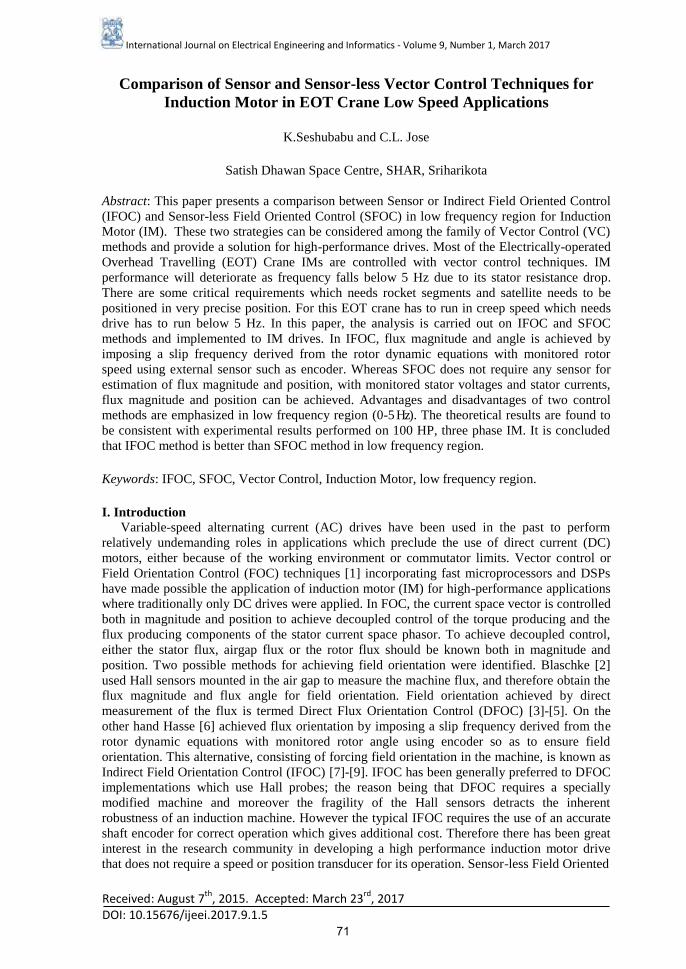
Figure 1. Stator current and rotor flux-linkage space phasors in the general reference frame
which is fixed to the rotor flux-linkage space phasor
𝑟′ 𝑟
′
𝑟
𝑖𝑠𝐷
𝑥
𝜃𝑟 𝜃𝑠𝑙 ∝𝑠 𝜌𝑟
𝑖𝑠𝑥 𝑖𝑠𝑦
𝑖𝑠𝑄
𝑖𝑟
𝑖,𝑖𝛹𝑟
𝑠𝑄
𝑠𝐷
𝑦
𝑟𝛹𝑟
𝜔𝑚𝑟
𝜔𝑟
𝑟𝛽
𝑟𝛼
K.Seshubabu, et al.
72
However, if instead of a reference frame fixed to the stator and rotor, a general reference
frame with direct and quadrature axes 𝑥, 𝑦 rotating at a general instantaneous speed (𝜔𝑚𝑟 =𝑑𝜌𝑟
𝑑𝑡) which is fixed to the rotor flux linkage space phasor as shown in Figure1. Torque can be
expressed as vector product of the rotor flux linkage and the stator current space phasors. The
rotor flux-linkage space phasor in the general reference frame can be expressed as
𝑟𝛹𝑟 = 𝐿𝑟𝑖𝛹𝑟 + 𝐿𝑚𝑖𝛹𝑟 = 𝑟𝑒−𝑗(𝜌𝑟−𝜃𝑟)= 𝑟𝑒
𝑗𝜃𝑟𝑒−𝑗𝜌𝑟 = 𝑟′𝑒−𝑗𝜌𝑟 = | 𝑟|𝑒
𝑗𝜌𝑟𝑒−𝑗𝜌𝑟 =
| 𝑟| = 𝛹𝑟𝑥 (2)
The stator current in the general reference frame can be expressed as
𝑖𝛹𝑟 = 𝑖𝑒−𝑗𝜌𝑟 = 𝑖𝑠𝑥 + 𝑗𝑖𝑠𝑦 (3)
Electromagnetic torque can be expressed in general reference frame as
𝑡𝑒 = 𝑘 𝑟𝛹𝑟X𝑖𝛹𝑟 =3
2𝑃
𝐿𝑚
𝐿𝑟𝛹𝑟𝑥𝑖𝑠𝑦 (∵ 𝑟𝛹𝑟 = 𝐿𝑟𝑖𝛹𝑟 + 𝐿𝑚𝑖𝛹𝑟 = | 𝑟| = 𝛹𝑟𝑥) (4)
The relationship between the stator current components in the stationary reference frame
(𝑖𝑠𝐷 , 𝑖𝑠𝑄) and the stator current components in the general reference frame (𝑖𝑠𝑥 , 𝑖𝑠𝑦) can be
obtained as
[𝑖𝑠𝑥
𝑖𝑠𝑦] = [
cos 𝜌𝑟 sin 𝜌𝑟
−𝑠𝑖𝑛𝜌𝑟 𝑐𝑜𝑠𝜌𝑟] [
𝑖𝑠𝐷
𝑖𝑠𝑄] (5)
Rotor magnetizing current in the general reference frame is defined in terms of stator and rotor-
current space phasors given by
𝑖𝑟 = 𝑖𝑚𝑟𝑥 + 𝑗𝑖𝑚𝑟𝑦 = 𝑟𝛹𝑟
𝐿𝑚
=𝛹𝑟𝑥
𝐿𝑚
= 𝑖𝑚𝑟𝑥 = | 𝑖𝑟| =𝐿𝑟𝑖𝛹𝑟 + 𝐿𝑚𝑖𝛹𝑟
𝐿𝑚
=𝐿𝑟
𝐿𝑚
𝑖𝛹𝑟 + 𝑖𝛹𝑟
= 𝑖𝛹𝑟 + (1 + 𝜎𝑟) 𝑖𝛹𝑟Where 𝜎𝑟 =𝐿𝑟𝑙
𝐿𝑚 𝑎𝑛𝑑 𝐿𝑟 = 𝐿𝑟𝑙 + 𝐿𝑚 (6)
Thereby torque eqn. can be represented as
𝑡𝑒 =3
2𝑃
𝐿𝑚2
𝐿𝑟| 𝑖𝑟|𝑖𝑠𝑦 =
3
2𝑃
𝐿𝑚
1+𝜎𝑟| 𝑖𝑟|𝑖𝑠𝑦 (7)
Eqn. 7, shows that electromagnetic torque can be controlled by independently controlling the
flux-producing current component | 𝑖𝑟| and torque-producing stator current component 𝑖𝑠𝑦 .
Under linear magnetic conditions 𝐿𝑚, 𝐿𝑟 and the term 3
2𝑃
𝐿𝑚
1+𝜎𝑟 are constant, and the expression
for the torque is similar to that of the separately excited dc machine.
The rotor voltage equation of the induction machine in general reference frame can be
expressed as
𝑅𝑟𝑖𝛹𝑟 +𝑑 𝑟𝛹𝑟
𝑑𝑡+ 𝑗(𝜔𝑚𝑟 − 𝜔𝑟) 𝑟𝛹𝑟 = 0 (8)
𝑅𝑟𝑖𝛹𝑟 + 𝐿𝑚𝑑| 𝑖𝑟|
𝑑𝑡+ 𝑗(𝜔𝑚𝑟 − 𝜔𝑟)𝐿𝑚| 𝑖𝑟| = 0 (∵ 𝑟𝛹𝑟 = 𝑟𝑒
−𝑗(𝜌𝑟−𝜃𝑟) = 𝐿𝑚| 𝑖𝑟|)
(9)
And from the above
𝑇𝑟𝑑| 𝑖𝑚𝑟|
𝑑𝑡+ | 𝑖𝑟| = 𝑖𝛹𝑟 − 𝑗(𝜔𝑚𝑟 − 𝜔𝑟)𝑇𝑟| 𝑖𝑟| (10)
Comparison of Sensor and Sensor-less Vector Control Techniques
73
𝑇𝑟𝑑| 𝑖𝑚𝑟|
𝑑𝑡+ | 𝑖𝑟| = 𝑖𝑠𝑥 (11)
𝜔𝑚𝑟 = 𝜔𝑟 +𝑖𝑠𝑦
𝑇𝑟| 𝑖𝑚𝑟| (12)
In eqn. (12) the term 𝑖𝑠𝑦
𝑇𝑟| 𝑖𝑚𝑟| represents the angular rotor frequency (angular slip frequency
of the rotor flux) 𝜔𝑠𝑙,and it follows that the angular speed of the rotor flux is equal to the sum
of the angular rotor speed and the angular slip frequency of the rotor flux. If | 𝑖𝑟| is constant,
it follows from eqn (11), that | 𝑖𝑟| = 𝑖𝑠𝑥, the modulus of the rotor flux-linkage space phasor
can be kept at a desired level by controlling the direct-axis stator current 𝑖𝑠𝑥 , the
electromagnetic torque is determined by the quadrature-axis stator current 𝑖𝑠𝑦.
In indirect rotor filed-oriented control method, the space angle of the rotor flux-linkage
space phasor (𝜌𝑟) is obtained as the sum of the monitored rotor angle (𝜃𝑟) and the computed
reference value of the slip angle(𝜃𝑠𝑙), where the slip angle gives the position of the rotor flux-
linkage space phasor relative to the rotor. These angles are shown in Figure1. The required
equations follow from eqn. (2), according to which the speed of the rotor magnetizing current
space phasor is
𝜔𝑚𝑟 = 𝜔𝑟 + 𝜔𝑠𝑙𝑟𝑒𝑓 (13)
Where 𝜔𝑟 is the rotor speed,
𝜔𝑟 =𝑑𝜃𝑟
𝑑𝑡 (14)
and 𝜔𝑠𝑙𝑟𝑒𝑓 is the reference value of the slip frequency,
𝜔𝑠𝑙𝑟𝑒𝑓 =𝑖𝑠𝑦
𝑇𝑟| 𝑖𝑟| (15)
Figure 2. Schematic of the Indirect rotor-flux-oriented control of current-controlled PWM
inverter-fed induction motor
𝑖𝑠𝑦𝑟𝑒𝑓
𝑖𝑠𝐶𝑟𝑒𝑓
IM
𝜃𝑟𝑟𝑒𝑓
𝜌𝑟
𝑖𝑠𝐶 𝑖𝑠𝐵
𝑖𝑠𝐴
3𝑃𝐿𝑚2
2𝐿𝑟
𝑖𝑟𝑟𝑒𝑓 𝑖𝑠𝑥𝑟𝑒𝑓
𝑖𝑠𝑦𝑟𝑒𝑓
𝑡𝑒𝑟𝑒𝑓
𝜔𝑠𝑙𝑟𝑒𝑓 𝜃𝑠𝑙𝑟𝑒𝑓
𝜃𝑟
𝜃𝑟 𝜔𝑟
𝜔𝑟𝑟𝑒𝑓
𝑝
𝑖𝑠𝐷𝑟𝑒𝑓
𝑇𝑟
1𝑃 ÷
Speed
controller
FG 1 + 𝑇𝑟𝑝
÷ Position
controller
PWM
modulator 𝑖𝑠𝐵𝑟𝑒𝑓 𝑖𝑠𝐴𝑟𝑒𝑓
𝜃𝑟
C
Rectifie
Current
controlled
PWM
Inverter 𝑖𝑠𝑄𝑟𝑒𝑓
𝑒𝑗𝜌𝑟 2->3
𝜌𝑟
K.Seshubabu, et al.
74

Furthermore
𝜔𝑚𝑟 =𝑑𝜌𝑟
𝑑𝑡 (16)
Thus it follows from eqns. (13)-(16) that
𝜌𝑟 = ∫ 𝜔𝑚𝑟𝑑𝑡 = ∫(𝜔𝑟 + 𝜔𝑠𝑙𝑟𝑒𝑓) 𝑑𝑡 = 𝜃𝑟 + 𝜃𝑠𝑙𝑟𝑒𝑓 (17)
The slip angle 𝜃𝑠𝑙𝑟𝑒𝑓 gives the position of the rotor magnetizing-current space phasor with
respect to the direct-axis of the reference frame fixed to the rotor.
𝜌𝑟 = 𝜃𝑟 + ∫ 𝜔𝑠𝑙𝑟𝑒𝑓𝑑𝑡 = 𝜃𝑟 + ∫𝑖𝑠𝑦
𝑇𝑟| 𝑖𝑟|𝑑𝑡 (18)
Which serves as the basis for obtaining the angle 𝜌𝑟 in the implementation of the rotor-flux-
oriented control of induction machine. According to eqn. (18) the division of the direct and
quadrature axis stator currents (𝑖𝑠𝑥𝑟𝑒𝑓,𝑖𝑠𝑦𝑟𝑒𝑓) is controlled by the slip frequency 𝜔𝑠𝑙 and the
two reference currents are used to determine the required slip frequency. When the rotor angle
and reference value of the slip frequency angle are added, the position of the rotor
magnetizing-current space phasor is obtained.
The schematic of the drive is shown in Figure 2. An incremental rotor position sensor is
used to obtain the rotor angle (𝜃𝑟) and the rotor speed (𝜔𝑟). The actual value of the rotor angle
(𝜃𝑟) is compared with its reference value (𝜃𝑟𝑒𝑓) and the resulting error serves as the input to
the position controller, which is a PI controller. The output of the position controller is the
reference value of the rotor speed (𝜔𝑟𝑟𝑒𝑓). This is compared with the monitored value of the
rotor speed and the error is supplied as the input to the speed controller. Its output is the
reference value of the electromagnetic torque (𝑡𝑒𝑟𝑒𝑓) and this is divided by the constant 3
2𝑃
𝐿𝑚2
𝐿𝑟
to yield the reference value of the stator current expressed in the rotor-flux-oriented reference
frame (𝑖𝑠𝑦𝑟𝑒𝑓). The monitored rotor speed serves as the input to the function generator FG
gives a reference value of the rotor magnetizing current ( 𝑖𝑟𝑟𝑒𝑓 ).
B. SFOC Technique-
Similar to IFOC technique, in this method also the stator currents of the induction machine
can be decoupled into flux and torque producing components with rotating vectors in a
complex coordinate system. Stator current components are transformed into a new rotating
reference frame, which rotates together with stator-flux-linkage space vector, which is termed
as Stator flux Field Oriented Control. The implementation of the stator flux FOC requires
information on the modulus and space angle (position) of the stator flux-linkage space phasor
which can be obtained by utilizing the monitored stator currents and voltages. Since in this
there is no sensor used for monitoring rotor speed and rotor speed can be calculated by
different estimation techniques. This technique also called as Sensor-less Field-Oriented
Control (SFOC). In the stationary reference frame the space phasor of the stator flux linkages
can be expressed as
𝑠 = 𝛹𝑠𝐷 + 𝑗𝛹𝑠𝑄 = ∫(𝑠 − 𝑅𝑠𝑖) 𝑑𝑡 (19)
Where
𝛹𝑠𝐷 = ∫(𝑢𝑠𝐷 − 𝑅𝑠𝑖𝑠𝐷)dt
𝛹𝑠𝑄 = ∫(𝑢𝑠𝑄 − 𝑅𝑠𝑖𝑠𝑄)dt
A general reference frame with direct and quadrature axes 𝑥, 𝑦 rotating at a general
instantaneous speed (𝜔𝑚𝑠 =𝑑𝜌𝑠
𝑑𝑡) which is fixed to the stator flux orientation as shown in
Comparison of Sensor and Sensor-less Vector Control Techniques
75
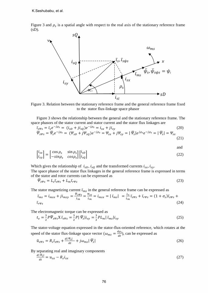
Figure 3 and 𝜌𝑠 is a spatial angle with respect to the real axis of the stationary reference frame
(sD).
Figure 3. Relation between the stationary reference frame and the general reference frame fixed
to the stator flux-linkage space phasor
Figure 3 shows the relationship between the general and the stationary reference frame. The
space phasors of the stator current and stator current and the stator flux linkages are
𝑖𝛹𝑠 = 𝑖𝑒−𝑗𝜌𝑠 = (𝑖𝑠𝐷 + 𝑗𝑖𝑠𝑄)𝑒−𝑗𝜌𝑠 = 𝑖𝑠𝑥 + 𝑗𝑖𝑠𝑦 (20)
𝑠𝛹𝑠 = 𝑠𝑒−𝑗𝜌𝑠 = (𝛹𝑠𝐷 + 𝑗𝛹𝑠𝑄)𝑒−𝑗𝜌𝑠 = 𝛹𝑠𝑥 + 𝑗𝛹𝑠𝑦 = | 𝑠|𝑒
𝑗𝜌𝑠𝑒−𝑗𝜌𝑠 = | 𝑠| = 𝛹𝑠𝑥
(21)
and
[𝑖𝑠𝑥
𝑖𝑠𝑦] = [
cos 𝜌𝑠 sin 𝜌𝑠
−𝑠𝑖𝑛𝜌𝑠 𝑐𝑜𝑠𝜌𝑠] [
𝑖𝑠𝐷
𝑖𝑠𝑄] (22)
Which gives the relationship of 𝑖𝑠𝐷 , 𝑖𝑠𝑄 and the transformed currents 𝑖𝑠𝑥 , 𝑖𝑠𝑦 .
The space phasor of the stator flux linkages in the general reference frame is expressed in terms
of the stator and rotor currents can be expressed as
𝑠𝛹𝑠 = 𝐿𝑠𝑖𝛹𝑠 + 𝐿𝑚𝑖𝛹𝑠 (23)
The stator magnetizing current 𝑖𝑠 in the general reference frame can be expressed as
𝑖𝑠 = 𝑖𝑚𝑠𝑥 + 𝑗𝑖𝑚𝑠𝑦 = 𝑠𝛹𝑠
𝐿𝑚=
𝛹𝑠𝑥
𝐿𝑚= 𝑖𝑚𝑠𝑥 = | 𝑖𝑠| =
𝐿𝑠
𝐿𝑚𝑖𝛹𝑠 + 𝑖𝛹𝑠 = (1 + 𝜎𝑠)𝑖𝛹𝑠 +
𝑖𝛹𝑠 (24)
The electromagnetic torque can be expressed as
𝑡𝑒 =3
2𝑃𝑠𝛹𝑠X 𝑖𝛹𝑠 =
3
2𝑃| 𝑠|𝑖𝑠𝑦 =
3
2𝑃𝐿𝑚| 𝑖𝑠|𝑖𝑠𝑦 (25)
The stator-voltage equation expressed in the stator-flux-oriented reference, which rotates at the
speed of the stator flux-linkage space vector (𝜔𝑚𝑠 =𝑑𝜌𝑠
𝑑𝑡), can be expressed as
𝑠𝛹𝑠 = 𝑅𝑠𝑖𝛹𝑠 +𝑑| 𝑠|
𝑑𝑡+ 𝑗𝜔𝑚𝑠| 𝑠| (26)
By separating real and imaginary components 𝑑| 𝑠|
𝑑𝑡= 𝑢𝑠𝑥 − 𝑅𝑠𝑖𝑠𝑥 (27)
𝑠𝑄
𝑟
𝑥
∝𝑠 𝜌𝑠
𝑖𝑠𝑥 𝑖𝑠𝑦
𝑖𝑠𝐷
𝑖𝑠𝑄
𝑖𝑠
𝑖
𝑖
𝑖, 𝑖𝜓𝑠
𝑠𝐷
𝑦
𝑠, 𝑠𝜓𝑠 = 𝜓𝑠𝑥
𝑖𝑠𝑥
𝑖
=
𝜔𝑚𝑠
K.Seshubabu, et al.
76
And the speed of the stator-flux space vector is obtained as
𝜔𝑚𝑠 =𝑢𝑠𝑦−𝑅𝑠𝑖𝑠𝑦
| 𝑠| (28)
From Eqn. (28) | 𝑠| can be estimated from ∫(𝑢𝑠𝑥 − 𝑅𝑠𝑖𝑠𝑥) 𝑑𝑡 and the angle 𝜌𝑠 can be
obtained by the integration of 𝜔𝑚𝑠. For estimation of rotor speed, rotor voltage space vector
equation in stationary reference frame can be expressed as
𝑅𝑟𝑖𝑟𝑑 +𝑑𝜓𝑟𝑑
𝑑𝑡+ 𝜔𝑟𝜓𝑟𝑞 = 0 (29)
Where 𝜓𝑟𝑑 = 𝐿𝑟𝑖𝑟𝑑 + 𝐿𝑚𝑖𝑠𝐷 (30)
𝜓𝑟𝑑 , 𝜓𝑟𝑞 and 𝑖𝑟𝑑, 𝑖𝑟𝑞 are instantaneous values of direct- and quadrature-axis rotor flux linkage
components and rotor current components respectively expressed in the stator reference frame.
Space phasor of the rotor flux linkages expressed in the stator reference frame can be expressed
as
𝑟′= 𝜓𝑟𝑑 + 𝑗𝜓𝑟𝑞 (31)
and
𝑟′=
𝐿𝑟
𝐿𝑚( 𝑠 − 𝐿𝑠
′ 𝑖) (32)
rotor speed can be expressed as
𝜔𝑟 = [−𝑑𝜓𝑟𝑑
𝑑𝑡−
𝜓𝑟𝑑
𝑇𝑟+
𝐿𝑚
𝑇𝑟𝑖𝑠𝐷] /Ψ𝑟𝑞 (33)
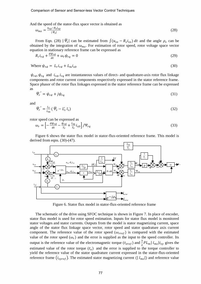
Figure 6 shows the stator flux model in stator-flux-oriented reference frame. This model is
derived from eqns. (30)-(47).
Figure 6. Stator flux model in stator-flux-oriented reference frame
The schematic of the drive using SFOC technique is shown in Figure 7. In place of encoder,
stator flux model is used for rotor speed estimation. Inputs for stator flux model is monitored
stator voltages and stator currents. Outputs from the model is stator magnetizing current, space
angle of the stator flux linkage space vector, rotor speed and stator quadrature axis current
component. The reference value of the rotor speed (𝜔𝑟𝑟𝑒𝑓) is compared with the estimated
value of the rotor speed (𝜔𝑟) and the error is supplied as the input to the speed controller. Its
output is the reference value of the electromagnetic torque (𝑡𝑒𝑟𝑒𝑓) and 3
2𝑃𝐿𝑚| 𝑖𝑠|𝑖𝑠𝑦 gives the
estimated value of the rotor torque (𝑡𝑒) and the error is supplied to the torque controller to
yield the reference value of the stator quadrature current expressed in the stator-flux-oriented
reference frame (𝑖𝑠𝑦𝑟𝑒𝑓). The estimated stator magnetizing current (| 𝑖𝑠|) and reference value
|𝑖𝑠|
𝑖𝑠𝑄
−
𝑖𝑠𝐷
𝜔𝑟
𝑑Ψ𝑠𝑄
𝑑𝑡
𝑑Ψ𝑠𝐷𝑑𝑡 𝑟
+ +
− +
+
−
−
+ Ψ𝑟𝑞
Ψ𝑟𝑑
Ψ𝑠𝑄 𝜌𝑠
Ψ𝑠𝐷 𝑢𝑠𝐷
𝑅𝑠
𝑅𝑠
𝑢𝑠𝑄
𝑢𝑠𝑥-𝑅𝑠𝑖𝑠𝑥
𝑢𝑠𝑦-𝑅𝑠𝑖𝑠𝑦
|𝑠|
𝜔𝑚𝑠
𝜌𝑠
𝑒−𝑗𝜌𝑠
1𝑝
÷ 1𝑝
P->R
𝐿𝑟𝐿𝑚
𝐿𝑟𝐿𝑚
𝑝 ÷
𝐿𝑚𝑇𝑟
𝐿𝑠′
𝐿𝑠′ 1
𝑇𝑟
𝑒−𝑗𝜌𝑠 𝑖𝑠𝑥
𝑖𝑠𝑦
+ −
− +
1
𝐿𝑚
Comparison of Sensor and Sensor-less Vector Control Techniques
77
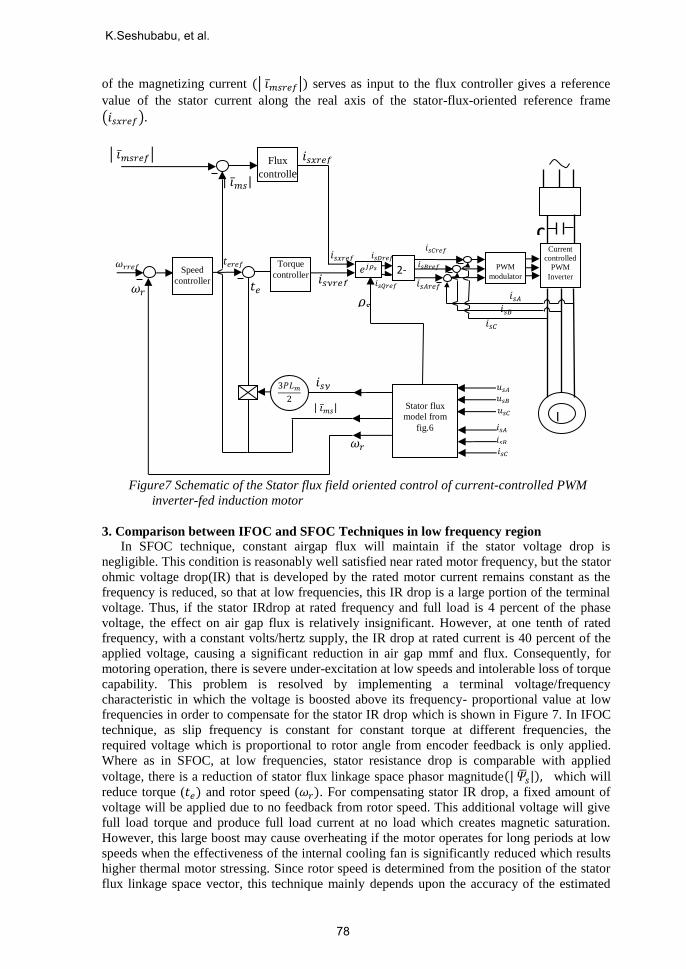
of the magnetizing current ( 𝑖𝑠𝑟𝑒𝑓 ) serves as input to the flux controller gives a reference
value of the stator current along the real axis of the stator-flux-oriented reference frame
(𝑖𝑠𝑥𝑟𝑒𝑓).
Figure7 Schematic of the Stator flux field oriented control of current-controlled PWM
inverter-fed induction motor
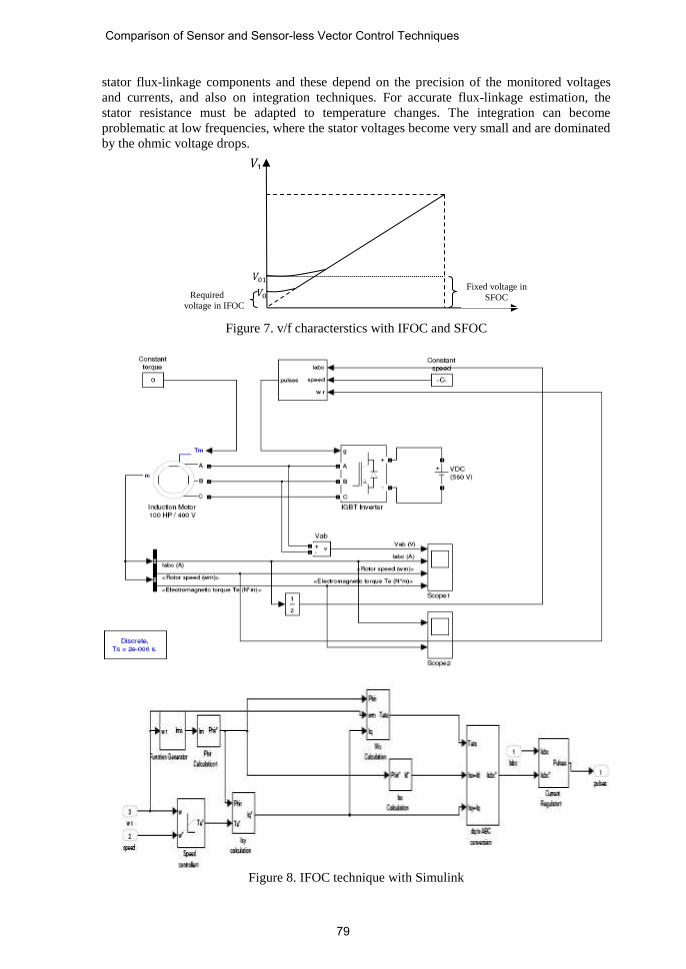
3. Comparison between IFOC and SFOC Techniques in low frequency region
In SFOC technique, constant airgap flux will maintain if the stator voltage drop is
negligible. This condition is reasonably well satisfied near rated motor frequency, but the stator
ohmic voltage drop(IR) that is developed by the rated motor current remains constant as the
frequency is reduced, so that at low frequencies, this IR drop is a large portion of the terminal
voltage. Thus, if the stator IRdrop at rated frequency and full load is 4 percent of the phase
voltage, the effect on air gap flux is relatively insignificant. However, at one tenth of rated
frequency, with a constant volts/hertz supply, the IR drop at rated current is 40 percent of the
applied voltage, causing a significant reduction in air gap mmf and flux. Consequently, for
motoring operation, there is severe under-excitation at low speeds and intolerable loss of torque
capability. This problem is resolved by implementing a terminal voltage/frequency
characteristic in which the voltage is boosted above its frequency- proportional value at low
frequencies in order to compensate for the stator IR drop which is shown in Figure 7. In IFOC
technique, as slip frequency is constant for constant torque at different frequencies, the
required voltage which is proportional to rotor angle from encoder feedback is only applied.
Where as in SFOC, at low frequencies, stator resistance drop is comparable with applied
voltage, there is a reduction of stator flux linkage space phasor magnitude(| 𝑠|), which will
reduce torque (𝑡𝑒) and rotor speed (𝜔𝑟). For compensating stator IR drop, a fixed amount of
voltage will be applied due to no feedback from rotor speed. This additional voltage will give
full load torque and produce full load current at no load which creates magnetic saturation.
However, this large boost may cause overheating if the motor operates for long periods at low
speeds when the effectiveness of the internal cooling fan is significantly reduced which results
higher thermal motor stressing. Since rotor speed is determined from the position of the stator
flux linkage space vector, this technique mainly depends upon the accuracy of the estimated
IM
𝑖𝑠𝑥𝑟𝑒𝑓
𝑡𝑒
| 𝑖𝑠|
| 𝑖𝑠|
𝑖𝑠𝑦
𝜔𝑟
𝑠𝐴
𝑖𝑠𝐴
Stator flux
model from
fig.6
𝑖𝑠𝐵 𝑖𝑠𝐶
𝑢𝑠𝐵 𝑢𝑠𝐴
𝑢𝑠𝐶
3𝑃𝐿𝑚2
𝑖𝑠𝐶𝑟𝑒𝑓
𝑡𝑒𝑟𝑒𝑓
𝑖𝑠𝐶
𝑖𝑠𝐵 𝑖𝑠𝐴
𝜔𝑟𝑟𝑒𝑓
𝑖𝑠𝑟𝑒𝑓 𝑖𝑠𝑥𝑟𝑒𝑓
𝑖𝑠𝑦𝑟𝑒𝑓 𝜔𝑟
𝑖𝑠𝐷𝑟𝑒𝑓 Torque
controller
Speed
controller
PWM
modulator
𝑖𝑠𝐵𝑟𝑒𝑓
𝑖𝑠𝐴𝑟𝑒𝑓
C
Rectifi
Current
controlled
PWM
Inverter 𝑖𝑠𝑄𝑟𝑒𝑓
𝑒𝑗𝜌𝑠
2->3
𝜌𝑠
Flux
controlle
r
K.Seshubabu, et al.
78
stator flux-linkage components and these depend on the precision of the monitored voltages
and currents, and also on integration techniques. For accurate flux-linkage estimation, the
stator resistance must be adapted to temperature changes. The integration can become
problematic at low frequencies, where the stator voltages become very small and are dominated
by the ohmic voltage drops.
Figure 7. v/f characterstics with IFOC and SFOC
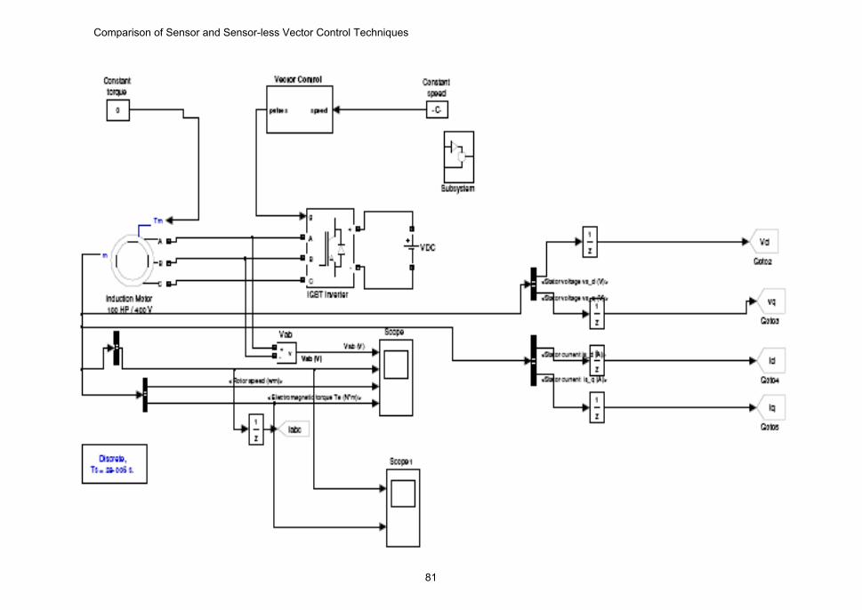
Figure 8. IFOC technique with Simulink
𝑉0
𝑉1
𝑉01
Required
voltage in IFOC
Fixed voltage in
SFOC
Comparison of Sensor and Sensor-less Vector Control Techniques
79
4. MATLAB Simulation
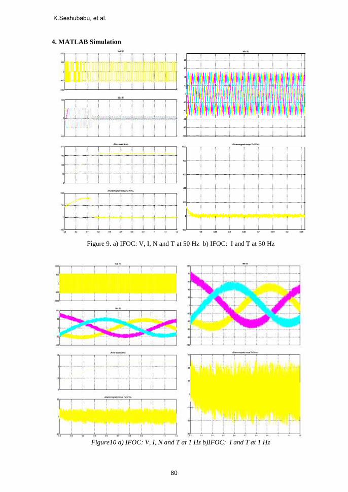
Figure 9. a) IFOC: V, I, N and T at 50 Hz b) IFOC: I and T at 50 Hz
Figure10 a) IFOC: V, I, N and T at 1 Hz b)IFOC: I and T at 1 Hz
K.Seshubabu, et al.
80
Comparison of Sensor and Sensor-less Vector Control Techniques
81
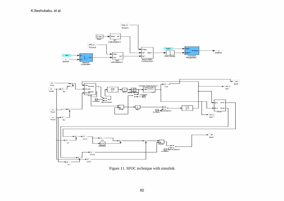
Figure 11. SFOC technique with simulink
K.Seshubabu, et al.
82
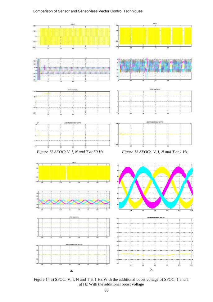
Figure 12 SFOC: V, I, N and T at 50 Hz Figure 13 SFOC: V, I, N and T at 1 Hz
Figure 14 a) SFOC: V, I, N and T at 1 Hz With the additional boost voltage b) SFOC: 1 and T
at Hz With the additional boost voltage
a.
b.
Comparison of Sensor and Sensor-less Vector Control Techniques
83

Figure 14 shows the SFOC technique at 1 Hz. Due to stator resistance drop, the flux
developed across the magnetic circuit is insufficient to develop the torque and increases the
speed. For compensating flux reduction, a suitable amount of additional voltage is added to
meet the flux requirement; it is developing more than required current with rated speed
irrespective of load.
V. Experimental Results
Theoretical analysis and Experimentation results were carried out on 60t critical handling
crane with hoist motion in up-ward direction. The motor details are shown in Table I. Table I
shows the 100 HP induction motor parameters, based on the above parameters theoretical
calculations are carried out.
Table 1. 60t VVVF drive based EOT crane motor details
Rated power 100 HP
Rated voltage 415V AC
Number of phase 3
Number of poles 8
Rated frequency 50 Hz
Line current 154 A
Rated speed 740 rpm
Rotor type Squirrel cage
No load slip 0.9%
Stator resistance (R1) 0.177 Ω
Stator reactance (X1) 5.63 Ω
Magnetizing reactance (Xm) 10.89 Ω
Rotor resistance (R2) 0.052 Ω
Rotor reactance (X2) 7.92 Ω
VVVF Drive rating 75 kW
Figure 15 depicts the theoretical values between v/f and slip/f characteristics of 100 HP
induction motor. From Figure15, it is observed that as frequency decreasing, voltage is
decreasing and slip is increasing. This is due to Figure4 states that flux was constant below the
rated frequency and shows that slip speed will be constant for constant torque. As the slip
speed is constant below the rated frequency, slip was increasing with decrease in frequency. As
the slip increases, rotor resistance referred to stator was decreasing with frequency thereby total
impedance is decreasing so that voltage is decreasing in proportionate with stator impedance
for constant motor torque. Figure 16 shows the theoretical and experimental results of 100 HP
induction motor with encoder feedback. Theoretical and experimental values are matching with
respect to voltage and current. From Figure16, it is observed that as frequency decreases,
voltage was decreasing in linear up to 5 Hz, below 5 Hz, voltage variation was not linear due
stator resistance voltage drop which is comparable with rotor resistance drop.
K.Seshubabu, et al.
84
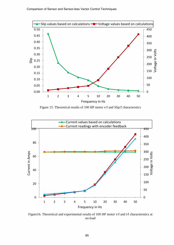
Figure 15. Theoretical results of 100 HP motor v/f and Slip/f characterstics
Figure16. Theoretical and experimental results of 100 HP motor v/f and i/f characteristics at
no-load
0
50
100
150
200
250
300
350
400
450
0.00
0.05
0.10
0.15
0.20
0.25
0.30
0.35
0.40
0.45
0.50
1 2 3 4 5 10 20 30 40 50
Vo
ltag
e in
Vo
lts
Slip
Frequency in Hz
Slip values based on calculations Voltage values based on calculations
0
50
100
150
200
250
300
350
400
450
0
20
40
60
80
100
1 2 3 4 5 10 20 30 40 50
Vo
ltag
e in
Vo
lts
Cu
rren
t in
Am
ps
Frequency in Hz
Current values based on calculationsCurrent readings with encoder feedback
Comparison of Sensor and Sensor-less Vector Control Techniques
85
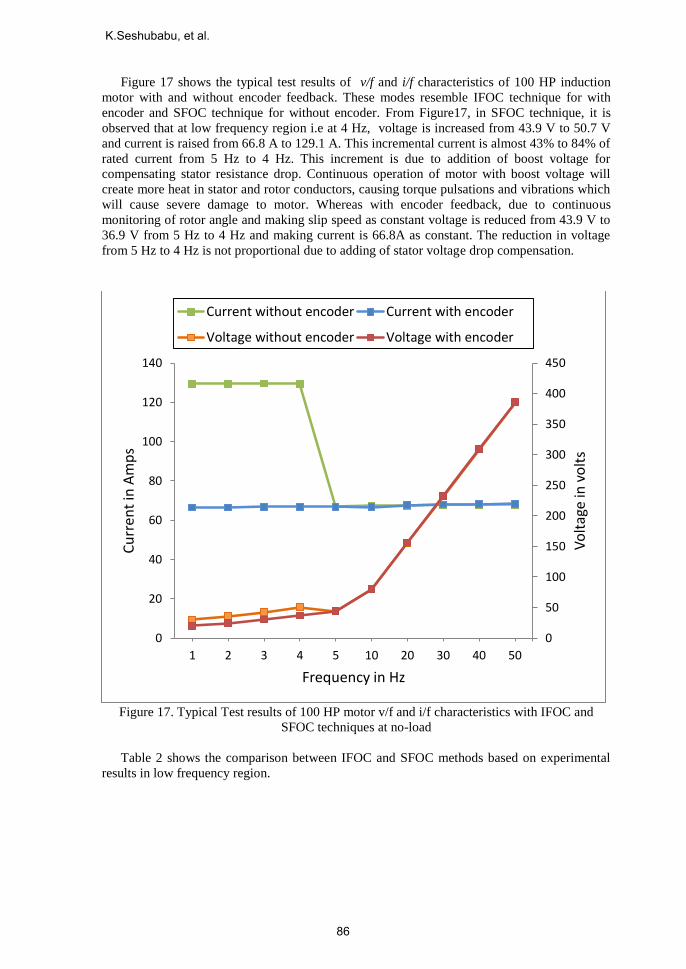
Figure 17 shows the typical test results of v/f and i/f characteristics of 100 HP induction
motor with and without encoder feedback. These modes resemble IFOC technique for with
encoder and SFOC technique for without encoder. From Figure17, in SFOC technique, it is
observed that at low frequency region i.e at 4 Hz, voltage is increased from 43.9 V to 50.7 V
and current is raised from 66.8 A to 129.1 A. This incremental current is almost 43% to 84% of
rated current from 5 Hz to 4 Hz. This increment is due to addition of boost voltage for
compensating stator resistance drop. Continuous operation of motor with boost voltage will
create more heat in stator and rotor conductors, causing torque pulsations and vibrations which
will cause severe damage to motor. Whereas with encoder feedback, due to continuous
monitoring of rotor angle and making slip speed as constant voltage is reduced from 43.9 V to
36.9 V from 5 Hz to 4 Hz and making current is 66.8A as constant. The reduction in voltage
from 5 Hz to 4 Hz is not proportional due to adding of stator voltage drop compensation.
Figure 17. Typical Test results of 100 HP motor v/f and i/f characteristics with IFOC and
SFOC techniques at no-load
Table 2 shows the comparison between IFOC and SFOC methods based on experimental
results in low frequency region.
0
50
100
150
200
250
300
350
400
450
0
20
40
60
80
100
120
140
1 2 3 4 5 10 20 30 40 50
Vo
ltag
e in
vo
lts
Cu
rren
t in
Am
ps
Frequency in Hz
Current without encoder Current with encoder
Voltage without encoder Voltage with encoder
K.Seshubabu, et al.
86
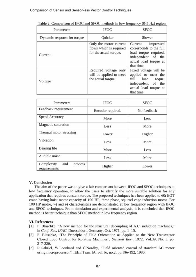
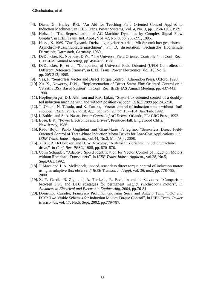
Table 2. Comparison of IFOC and SFOC methods in low frequency (0-5 Hz) region
Parameters IFOC SFOC
Dynamic response for torque Quicker Slower
Current
Only the motor current
flows which is required
for the actual torque.
Current impressed
corresponds to the full
load torque required,
independent of the
actual load torque at
that time.
Voltage
Required voltage only
will be applied to meet
the actual torque.
Fixed voltage will be
applied to meet the
full load toque,
independent of the
actual load torque at
that time.
Parameters IFOC SFOC
Feedback requirement Encoder required. No feedback
Speed Accuracy More Less
Magnetic saturation Less More
Thermal motor stressing Lower Higher
Vibration Less More
Bearing life More Less
Audible noise Less More
Complexity and process
requirements Higher Lower
V. Conclusion
The aim of the paper was to give a fair comparison between IFOC and SFOC techniques at
low frequency operation, to allow the users to identify the more suitable solution for any
application that requires constant torque. The proposed techniques has been applied to 60t EOT
crane having hoist motor capacity of 100 HP, three phase, squirrel cage induction motor. For
100 HP motor, v/f and i/f characteristics are demonstrated at low frequency region with IFOC
and SFOC techniques. From simulation and experimental analysis, it is concluded that IFOC
method is better technique than SFOC method in low frequency region.
VI. References
[1]. F. Blaschke, “A new method for the structural decoupling of A.C. induction machines,”
in Conf. Rec. IFAC, Duesseldorf, Germany, Oct. 1971, pp. 1–15.
[2]. F. Blaschke, “The Principle of Field Orientation as Applied to the New Transvector
Closed Loop Control for Rotating Machines”, Siemens Rev., 1972, Vol.39, No. 5, pp.
217-220.
[3]. R.Gabriel, W.Leonhard and C.Nordby, “Field oriented control of standard AC motor
using microprocessor”, IEEE Tran. IA, vol.16, no.2, pp.186-192, 1980.
Comparison of Sensor and Sensor-less Vector Control Techniques
87
[4]. Diana, G., Harley, R.G, "An Aid for Teaching Field Oriented Control Applied to
Induction Machines", in IEEE Trans. Power Systems, Vol. 4, No. 3, pp. 1258-1262,1989.
[5]. Holtz, J, "The Representation of AC Machine Dynamics by Complex Signal Flow
Graphs", in IEEE Trans. Ind. Appl., Vol. 42, No. 3, pp. 263-271, 1995.
[6]. Hasse, K. 1969. "Zur Dynamic Drehzahlgeregelter Antriebe Mit Stromrichter gespeisten
Asynchron-Kuzschlublaufermaschinen", Ph. D. dissertation, Technische Hochschule
Darmstadt, Darmstadt, Germany, 1969.
[7]. DeDoncker, R., Novotny, D.W., "The Universal Field Oriented Controller", in Conf. Rec.
IEEE-IAS Annual Meeting, pp. 450-456, 1988.
[8]. DeDoncker, R., et al., "Comparison of Universal Field Oriented (UFO) Controllers in
Different Reference Frames", in IEEE Trans. Power Electronics, Vol. 10, No. 2.
pp. 205-213, 1995.
[9]. Vas, P, "Sensorless Vector and Direct Torque Control", Clarendon Press, Oxford, 1998.
[10]. Xu, X., Nowotny, D.W., "Implementation of Direct Stator Flux Oriented Control on a
Versatile DSP Based System", in Conf. Rec. IEEE-IAS Annual Meeting, pp. 437-443,
1990.
[11]. Hopfensperger, D.J. Atkinson and R.A. Lakin, “Stator-flux-oriented control of a doubly-
fed induction machine with and without position encoder” in IEE 2000 pp: 241-250.
[12]. T. Ohtani, N. Takada, and K. Tanaka, “Vector control of induction motor without shaft
encoder,” IEEE Trans. Indust. Applicat., vol. 28, pp. 157–164, Jan./Feb. 1992.
[13]. I. Boldea and S. A. Nasar, Vector Control of AC Drives. Orlando, FL: CRC Press, 1992.
[14]. Bose, B.K., "Power Electronics and Drives", Prentice-Hall, Englewood Cliffs,
New Jersey, 1986.
[15]. Radu Bojoi, Paolo Guglielmi and Gian-Mario Pellegrino, “Sensorless Direct Field-
Oriented Control of Three-Phase Induction Motor Drives for Low-Cost Applications”, in
IEEE Trans. Indust. Applicat., vol.44, No.2, Mar./Apr. 2008.
[16]. X. Xu, R. DeDoncker, and D. W. Novotny, “A stator flux oriented induction machine
drive,” in Conf. Rec. PESC, 1988, pp. 870–876.
[17]. Colin Schauder, “Adaptive Speed Identification for Vector Control of Induction Motors
without Rotational Transducers”, in IEEE Trans. Indust. Applicat., vol.28, No.5,
Sept./Oct. 1992.
[18]. J. Maes and J. A. Melkebeek, “speed-sensorless direct torque control of induction motor
using an adaptive flux observer,” IEEE Trans.on Ind Appl, vol. 36, no.3, pp. 778-785,
2000.
[19]. X. T. Garcia, B. Zigmund, A. Terlizzi , R. Pavlanin and L. Salvatore, “Comparison
between FOC and DTC stratagies for permanent magnet synchronous motors”, in
Advances in Electrical and Electronic Engineering, 2004, pp.76-81
[20]. Domenico Casadei, Francesco Profumo, Giovanni Serra and Angelo Tani, “FOC and
DTC: Two Viable Schemes for Induction Motors Torque Control”, in IEEE Trans. Power
Electronics, vol. 17, No.5, Sept. 2002, pp.779-787.
K.Seshubabu, et al.
88
K. Seshubabu received the B.Tech degree in Electrical& Electronics
engineering from JNTU, Hyderabad in 2002, and the M.E. degree in
Electricalengineering with specialization in power electronics from
R.G.P.V University, Bhopal, in 2005.He joined at Indian Space
research Organisation (ISRO),Satish Dhawan Space Centre (SDSC),
SHAR, Sriharikota in 2005. Since 2005, he has been with the SDSC,
SHAR, as a Scientist/Engineer, where he is primarily responsible for
realization of Electrical systems of GSLV Mk-III ground based facilities in SDSC.
His research interests include Variable Voltage Variable Frequency drives, SMPS
topologies, power-factor correction and powersystems in general.
Currently he is supporting electrical systems for Mk-III integration activities and
satellite propellant filling activities. He is a team member for Second Vehicle
Assembly Building (SVAB) project.
C. L. Jose obtained his B.E Electrical Degree from Bangalore
University and having 35 years of experience in various electrical
power controls system area of ground based systems of Indian Space
research Organisation (ISRO).He is instrumental in planning and
realising various electrical systems at Satellite Centre, Bangalore,
Satish Dhawan Space Centre, Sriharikota meeting requisite
redundancy, reliability to meet successful space programs. His
research interests include Variable Voltage Variable Frequency drives, Uninterrupted
Power Supplies and power systems in general. Currently serving ISRO as Dy.General
Manager for Electronics, Electrical and Checkout facilities for launch vehicles at
SatishDhawan Space Centre, Sriharikota.
Comparison of Sensor and Sensor-less Vector Control Techniques
89