compatibility and interoperability
TRANSCRIPT
8/18/2019 Compatibility and Interoperability
http://slidepdf.com/reader/full/compatibility-and-interoperability 1/5
1
Abstract-- Recent development of electronic instrument
transformers and use of digital relays allow the development of
an all-digital protection system, where the traditional analog,
hardwired, interface has been replaced with a digital
communication link (process bus) based on IEC 61850-9-2
standard. An all-digital system should provide compatibility and
interoperability so that different electronic instrument
transformers can be connected to different digital relays (under a
multi-vendor connection). Since the novel all-digital system
composed of IEDs from multiple vendors has never been
implemented and/or tested in practice so far, its performance
needs to be evaluated. This paper presents a methodology for
performance and compatibility evaluation of an all-digital
protection system. The test results obtained using a digital
simulator test bench and comparison of the compatibility of
systems provided by different manufactures are discussed.
Index Terms--compatibility, interoperability, IEC 61850,
performance evaluation, process bus, protective relaying, relay
testing, optical transformers
I. INTRODUCTION
ELAY testing is a very important issue when applying the
protective relays. Vendors need an evaluation tool to
validate the design of the relay logic and communication.
Utilities need a tool to compare the performance of different
relays, calibrate relay settings and perform troubleshooting.
The recent development of optical and Hall Effect instrument
transformers and the use of digital relays enable the
development of an all-digital protection system. Different
components of such system communicate using digital
communication protocol. The output of the electronic current
and voltage transformers are sampled (digital) signals, which
after combining in merging units can be connected to digital
relays through an IEC 61850-9-2 digital process bus [1].
Compatibility and interoperability are one of the most
important features of IEC 61850. Although many
This work was supported by PSerc project titled, “Digital Protection System
Using Optical Instrument Transformers and Digital Relays Interconnected by an
IEC 61850-9-2 Digital Process Bus”
Z. Djekic is currently with American Electric Power Inc. Columbus, OH (e-mail:
zdjekic@ aep.com)
L. Portillo is with Dashiell Corporation, Houston, TX (e-mail:
M. Kezunovic is with the Department of Electrical and Computer Engineering,
Texas A&M University, College Station, TX (e-mail: [email protected]).
interoperability tests have been performed at the bay level and
the IEC 61850-9-1 interoperability at the process level, the
all-digital protection system containing different electronic
instrument transformers connected to different digital relays
by an IEC 61850-9-2 process bus was not described in the
literature yet. Compatibility and interoperability evaluation of
the all-digital protection system assumes two kinds of test,
conformance and performance test. IEC 61850-10 gives
guidance for the conformance tests of Intelligent Electronic
Devices (IEDs) interconnected in an all digital protection
systems [2]. The performance tests allow more extensive
assessment and can be used to determine the performance
characteristics of the overall system [3]. Evaluation of the all-
digital system performance is necessary in order to recognize
all possible conditions when protection system may miss-
operate, or operate with unacceptable performance (reduced
selectivity, increased operating time, etc). Identifying these
abnormal situations is important for two reasons: a)
recognizing possible conditions for incorrect operation, b)
proving that the novel implementation will not translate in
degrading protection system performance. In [4] authorspropose a methodology of compatibility and interoperability
evaluation for all-digital protection system through automatic
implementation of application testing. This methodology is
now used as a base for compatibility and interoperability
testing of all digital protection systems composed using
components from multiple vendors.
The paper is organized as follows. Section II introduces the
compatibility and interoperability evaluation; Section III
defines the evaluation methodology; Section IV discusses test
results and Section V conclusions.
II. COMPATIBILITY AND INTEROPERABILITY
Compatibility means the ability of two or more IEDs to
perform requested functions (protection, control, metering,
etc) using IEC 61850 standard for communication and data
exchange. According to IEC 61850 interoperability is ability
of IEDs or substation automation systems from different
vendors to execute bi-directional data exchange functions, in
a manner that allows them to operate effectively together.
Unlike interoperability, the IEC 61850 standard was never
intended to ensure interchangeability of IEDs [3]. However,
interchangeability of the transducer system (comprised of
Compatibility and Interoperability Evaluation of
All-digital Protection Systems Based on IEC
61850-9-2 Communication StandardZarko Djekic, Student Member, IEEE , Levi Portillo and Mladen Kezunovic, Fellow, IEEE
R
©2008 IEEE.

8/18/2019 Compatibility and Interoperability
http://slidepdf.com/reader/full/compatibility-and-interoperability 2/5
2
current and/or voltage sensors and merging units) and process
bus (made of copper or fiber wires and an Ethernet switch) is
not only a possibility but also a highly desirable feature of the
all-digital system, allowing utilities to choose between
different sensors and fast Ethernet switches without
restrictions.
Performing compatibility and interoperability tests gives
ability to make conclusion about possible interchangeability
between protection systems components made by differentvendors. As mentioned, compatibility and interoperability
evaluation of the all digital protection system requires two
kinds of test, namely conformance and performance test.
Conformance tests belong to certification tests which aim at
verifying whether an IED satisfies the criteria specified by
certain standard or authority. These tests are performed at the
vendor’s laboratories or at independent test institutes. Criteria
for performance evaluation of the protection system are not a
new topic and have been investigated in different research
efforts [5], [6]. Although they have proven to be effective to
evaluate the performance of conventional protection system,
they need to be extended to be applicable for all-digital
systems. Performance tests belong to application tests whichaim at verifying the behavior of the protection system, the
accuracy and operating times under various conditions. For
the all-digital protection system, the interests for performance
tests are the trip/no trip decisions and the operating times.
In [4] authors propose how the compatibility and
interoperability evaluation of all-digital protection system is
performed through protection system performance tests.
A. Performance Indices
This paper follows selection of the performance indices
adopted in [4] to meet the needs of the all-digital protection
system. Two kinds of indices are used for performance
evaluation:The performance index of protection system P when fed by
exposure E is denoted by PPI E P. The average performance
index of protection system P is defined as:
PPI P=1
N ∑
E ∈EB
PPI E P where N is the number of exposures
There are two types of protection performance indicescalculation methods, namely the trip decision method and triptime method respectively. For the trip decision method:
N
N N sPPI E
P01 +
== where N 1 and, N
0 denotes number
of correct trip/restraints and N is the total number of
exposures
For the trip time method:
t E P DPPI = where Dt
stand for the trip time of
the tested protection system.
B. Compatibility Index
The compatibility index of protection system P1 and P2
when fed by the same test signal E is defined as:
PCI E P1,P2=|PPI
E P1-PPI
E P2|
The average compatibility index of protection system P1 and
P2 is defined as:
PCI P1,P2=1
N
∑
E ∈EB
|PPI E P1-PPI
E P2|
The protection system includes the transducer system(sensor and merging unit), the process bus (the Ethernet LAN)and the protective relay. By definition, the smaller the PCI,the better compatibility and interoperability.
III. EVALUATION METHODOLOGY
The compatibility indices, defined in the previous section,
are calculated by analyzing output signals of IEDs from
different manufacturers combined into a test system. Three
transducer sets (composed from current sensors and merging
units), two 100Mbit/sec Ethernet switches and one digital
relay where available for testing. Generic evaluation systems
diagram is as shown on Fig 1.
Fig. 1. Generic test evaluation setup
Simulation scenarios define the power system events to becreated and replayed into the modeled referent protection
systems and the all-digital protection system assembled in the
lab. These events are simulated using a sequence of circuit
breaker switching corresponding to various power system
conditions. Any particular scenario is defined by two
parameters: Time at which the event starts and finishes and
scenarios shown in table I.
TABLE I. SIMULATION SCENARIO, OVERCURRENT PROTECTION
Simulated scenarios are selected to create those power
system conditions in which correct operation of the protection
system is critical [7]. Voltage sensors were not available from
all vendors so scenarios were limited to those that do not
require directionality (forward zone 20% and 70%).
Overcurrent protection is expected to operate (issuing a trip
command) for faults in the forward zone of protection.
Features of the tested overcurrent relay function are:
8/18/2019 Compatibility and Interoperability
http://slidepdf.com/reader/full/compatibility-and-interoperability 3/5
3
• Phase time overcurrent protection as backup protection
• Residual time overcurrent protection
Settings of the relays are:
• Nominal input current of relay model is In=5A
• Pickup current is set to 1.5 times the nominal value
• Very inverse time-current characteristic was
used. This characteristic is defined as:
t
operate
=13.5×k
I n-1
k was chosen as: k=0.025
A total of 120 different exposures (1200 tests since each
exposure is replayed 10 times) are generated for the
overcurrent protection testing.
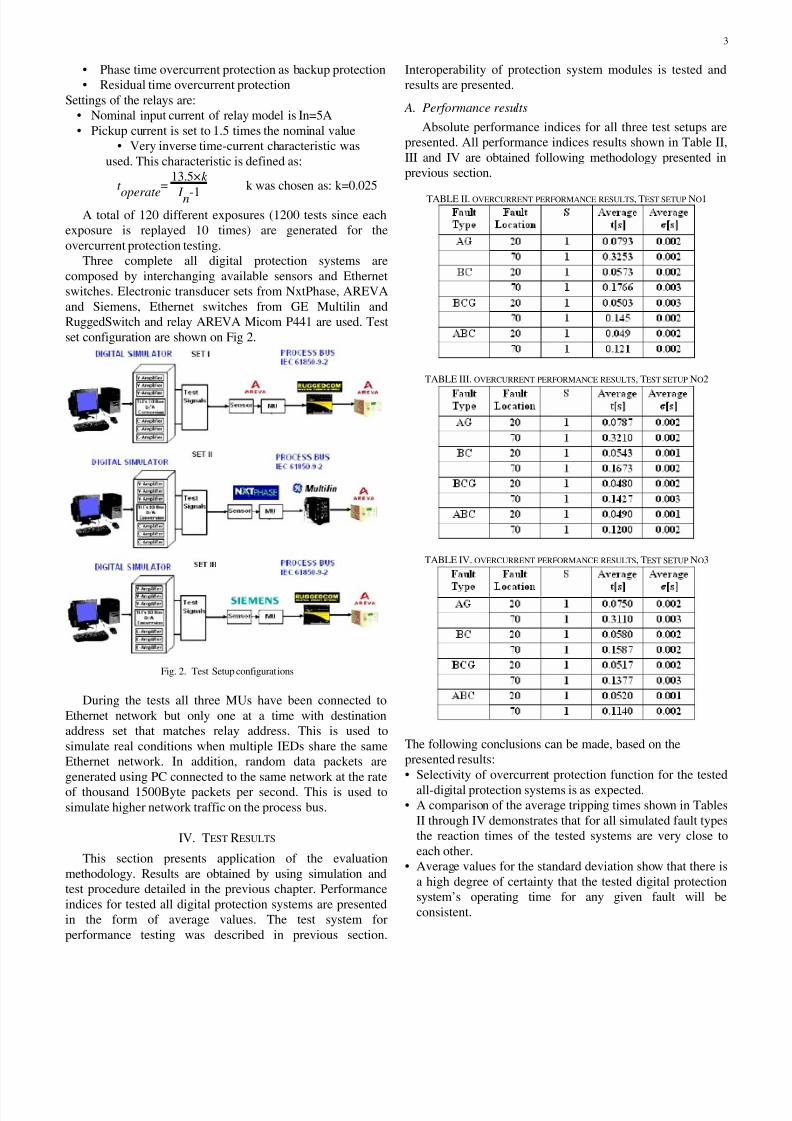
Three complete all digital protection systems are
composed by interchanging available sensors and Ethernet
switches. Electronic transducer sets from NxtPhase, AREVA
and Siemens, Ethernet switches from GE Multilin and
RuggedSwitch and relay AREVA Micom P441 are used. Test
set configuration are shown on Fig 2.
Fig. 2. Test Setup configurations
During the tests all three MUs have been connected to
Ethernet network but only one at a time with destination
address set that matches relay address. This is used to
simulate real conditions when multiple IEDs share the same
Ethernet network. In addition, random data packets are
generated using PC connected to the same network at the rate
of thousand 1500Byte packets per second. This is used to
simulate higher network traffic on the process bus.
IV. TEST RESULTS
This section presents application of the evaluation
methodology. Results are obtained by using simulation and
test procedure detailed in the previous chapter. Performance
indices for tested all digital protection systems are presented
in the form of average values. The test system for
performance testing was described in previous section.
Interoperability of protection system modules is tested and
results are presented.
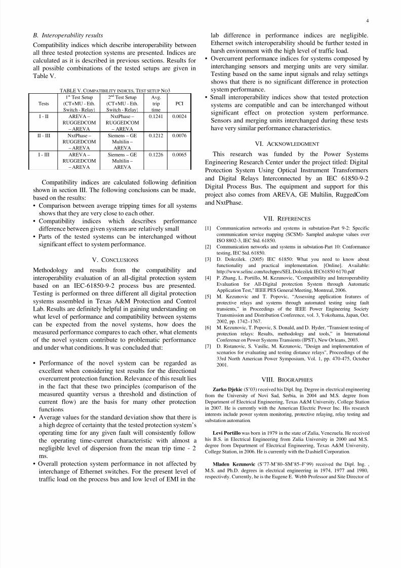
A. Performance results
Absolute performance indices for all three test setups are
presented. All performance indices results shown in Table II,
III and IV are obtained following methodology presented in
previous section.
TABLE II. OVERCURRENT PERFORMANCE RESULTS, TEST SETUP NO1
TABLE III. OVERCURRENT PERFORMANCE RESULTS, TEST SETUP NO2
TABLE IV. OVERCURRENT PERFORMANCE RESULTS, TEST SETUP NO3
The following conclusions can be made, based on the
presented results:
• Selectivity of overcurrent protection function for the tested
all-digital protection systems is as expected.• A comparison of the average tripping times shown in Tables
II through IV demonstrates that for all simulated fault types
the reaction times of the tested systems are very close to
each other.
• Average values for the standard deviation show that there is
a high degree of certainty that the tested digital protection
system’s operating time for any given fault will be
consistent.
8/18/2019 Compatibility and Interoperability
http://slidepdf.com/reader/full/compatibility-and-interoperability 4/5
4
B. Interoperability results
Compatibility indices which describe interoperability between
all three tested protection systems are presented. Indices are
calculated as it is described in previous sections. Results for
all possible combinations of the tested setups are given in
Table V.
TABLE V. COMPATIBILITY INDICES, TEST SETUP NO3
Tests 1
st
Test Setup(CT+MU - Eth.
Switch - Relay)
2
nd
Test Setup(CT+MU - Eth.
Switch - Relay)
Avg.trip
time
PCI
I - II AREVA –
RUGGEDCOM
– AREVA
NxtPhase –
RUGGEDCOM
– AREVA
0.1241 0.0024
II - III NxtPhase –
RUGGEDCOM
– AREVA
Siemens – GE
Multilin –
AREVA
0.1212 0.0076
I - III AREVA –
RUGGEDCOM
– AREVA
Siemens – GE
Multilin –
AREVA
0.1226 0.0065
Compatibility indices are calculated following definition
shown in section III. The following conclusions can be made,
based on the results:• Comparison between average tripping times for all systems
shows that they are very close to each other.
• Compatibility indices which describes performance
difference between given systems are relatively small
• Parts of the tested systems can be interchanged without
significant effect to system performance.
V. CONCLUSIONS
Methodology and results from the compatibility and
interoperability evaluation of an all-digital protection system
based on an IEC-61850-9-2 process bus are presented.
Testing is performed on three different all digital protection
systems assembled in Texas A&M Protection and Control
Lab. Results are definitely helpful in gaining understanding on
what level of performance and compatibility between systems
can be expected from the novel systems, how does the
measured performance compares to each other, what elements
of the novel system contribute to problematic performance
and under what conditions. It was concluded that:
• Performance of the novel system can be regarded as
excellent when considering test results for the directional
overcurrent protection function. Relevance of this result lies
in the fact that these two principles (comparison of the
measured quantity versus a threshold and distinction of
current flow) are the basis for many other protection
functions
• Average values for the standard deviation show that there is
a high degree of certainty that the tested protection system’s
operating time for any given fault will consistently follow
the operating time-current characteristic with almost a
negligible level of dispersion from the mean trip time - 2
ms.
• Overall protection system performance in not affected by
interchange of Ethernet switches. For the present level of
traffic load on the process bus and low level of EMI in the
lab difference in performance indices are negligible.
Ethernet switch interoperability should be further tested in
harsh environment with the high level of traffic load.
• Overcurrent performance indices for systems composed by
interchanging sensors and merging units are very similar.
Testing based on the same input signals and relay settings
shows that there is no significant difference in protection
system performance.
• Small interoperability indices show that tested protectionsystems are compatible and can be interchanged without
significant effect on protection system performance.
Sensors and merging units interchanged during these tests
have very similar performance characteristics.
VI. ACKNOWLEDGMENT
This research was funded by the Power Systems
Engineering Research Center under the project titled: Digital
Protection System Using Optical Instrument Transformers
and Digital Relays Interconnected by an IEC 61850-9-2
Digital Process Bus. The equipment and support for this
project also comes from AREVA, GE Multilin, RuggedCom
and NxtPhase.
VII. REFERENCES
[1]
Communication networks and systems in substation-Part 9-2: Specific
communication service mapping (SCSM)- Sampled analogue values over
ISO 8802-3, IEC Std. 61850.
[2]
Communication networks and systems in substation-Part 10: Conformance
testing, IEC Std. 61850.
[3]
D. Dolezilek. (2005) IEC 61850: What you need to know about
functionality and practical implementation. [Online]. Available:
http://www.selinc.com/techpprs/SEL Dolezilek IEC61850 6170.pdf
[4] P. Zhang, L. Portillo, M. Kezunovic, "Compatibility and Interoperability
Evaluation for All-Digital protection System through Automatic
Application Test," IEEE PES General Meeting, Montreal, 2006.
[5]
M. Kezunovic and T. Popovic, “Assessing application features ofprotective relays and systems through automated testing using fault
transients,” in Proceedings of the IEEE Power Engineering Society
Transmission and Distribution Conference, vol. 3, Yokohama, Japan, Oct.
2002, pp. 1742–1767.
[6]
M. Kezunovic, T. Popovic, S. Donald, and D. Hyder, “Transient testing of
protection relays: Results, methodology and tools,” in International
Conference on Power Systems Transients (IPST), New Orleans, 2003.
[7]
D. Ristanovic, S. Vasilic, M. Kezunovic, "Design and implementation of
scenarios for evaluating and testing distance relays", Proceedings of the
33rd North American Power Symposium, Vol. 1, pp. 470-475, October
2001.
VIII. BIOGRAPHIES
Zarko Djekic (S’03) received his Dipl. Ing. Degree in electrical engineering
from the University of Novi Sad, Serbia, in 2004 and M.S. degree fromDepartment of Electrical Engineering, Texas A&M University, College Station
in 2007. He is currently with the American Electric Power Inc. His research
interests include power system monitoring, protective relaying, relay testing and
substation automation.
Levi Portillo was born in 1979 in the state of Zulia, Venezuela. He received
his B.S. in Electrical Engineering from Zulia University in 2000 and M.S.
degree from Department of Electrical Engineering, Texas A&M University,
College Station, in 2006. He is currently with the Dashiell Corporation.
Mladen Kezunovic (S’77-M’80–SM’85–F’99) received the Dipl. Ing. ,
M.S. and Ph.D. degrees in electrical engineering in 1974, 1977 and 1980,
respectively. Currently, he is the Eugene E. Webb Professor and Site Director of

8/18/2019 Compatibility and Interoperability
http://slidepdf.com/reader/full/compatibility-and-interoperability 5/5
5
Power Engineering Research Center (PSerc), an NSF I/UCRC at Texas A&M
University He worked for Westinghouse Electric Corp., Pittsburgh, PA, 1979-
1980 and the Energoinvest Company, in Europe 1980-1986. He was also a
Visiting Associate Professor at Washington State University, Pullman, 1986-
1987. His main research interests are digital simulators and simulation methods
for relay testing as well as application of intelligent methods to power system
monitoring, control, and protection. Dr. Kezunovic is a member of CIGRE and
Registered Professional Engineer in Texas.