compendio de publicaciones
TRANSCRIPT

TESIS DOCTORAL
COMPENDIO DE PUBLICACIONES
DESIGN OF SELF-LOCKING PLANETARY GEAR TRAINS FOR REHABILITATION ENGINEERING
AND MOBILITY DEVICES
DOCTORADO EN INGENIERÍA MECÁNICA Y DE ORGANIZACIÓN INDUSTRIAL
Presenta:
Gaspar Rodríguez Jiménez
Directores: Francisco Javier Alonso Sánchez
David Rodríguez Salgado
Tutor:
José María del Castillo Granados
Sevilla, Diciembre de 2018

Design of self-locking planetary gear trains for rehabilitation engineering and mobility devices
2
TESIS DOCTORAL
COMPENDIO DE PUBLICACIONES
DISEÑO DE TRENES DE ENGRANAJES PLANETARIOS AUTORRETENIBLES PARA
INGENIERÍA DE REHABILITACIÓN Y DISPOSITIVOS DE MOBILIDAD
DOCTORADO EN INGENIERÍA MECÁNICA Y DE
ORGANIZACIÓN INDUSTRIAL
Presenta: Gaspar Rodríguez Jiménez
Directores:
Francisco Javier Alonso Sánchez David Rodríguez Salgado
Tutor:
José María del Castillo Granados
Sevilla, Diciembre de 2018

Design of self-locking planetary gear trains for rehabilitation engineering and mobility devices
3
“When you want to know how things really work, study them when they are coming apart”
William Gibson.

Design of self-locking planetary gear trains for rehabilitation engineering and mobility devices
4
Resumen
El número de personas que padecen debilidad muscular y que necesitan dispositivos
externos que asistan o rehabiliten su marcha es cada vez mayor. Existe una gran
variedad de dispositivos que estos pacientes pueden utilizar, entre ellos las ortesis de
rodilla con bloqueo durante la fase de apoyo. Este tipo de ortesis permiten un control
de la articulación durante el ciclo de la marcha, tanto en la fase de balanceo, como en la
fase de apoyo. Dentro de este grupo, la gran mayoría utilizan sensores y/o actuadores
para su correcto funcionamiento.
En este contexto, esta tesis doctoral presenta un estudio y un desarrollo de una órtesis
de rodilla con control en la fase de apoyo. El dispositivo es totalmente mecánico y se
bloquea para cualquier ángulo de flexión de la rodilla. El sistema principal de este
dispositivo es un tren de engranajes planetarios autorretenibles que se encarga, por un
lado, de permitir el movimiento de la articulación durante la fase de balanceo de la
marcha, y por otro, de bloquearlo durante la fase de apoyo ante la presencia de
cualquier ángulo de flexión de la rodilla. De esta manera se consigue un control de la
marcha sin necesidad de actuadores ni sensores.
A pesar de la gran evolución tecnológica de las sillas de ruedas, la mayoría de ellas siguen
siendo de propulsión manual debido a bajo precio, ligereza, transportabilidad y
capacidad de plegado. Sin embargo, uno de los grandes obstáculos para los usuarios de
sillas de ruedas es la subida de rampas ya que suponen una barrera para el desarrollo
de las actividades diarias. Además, la subida de pendientes requiere esfuerzos
musculares elevados.
En este trabajo, se propone la adaptación de un sistema de engranajes planetarios a las
sillas de ruedas manuales para facilitar la labor de subida de rampas a la vez que
disminuir el esfuerzo ejercido por el usuario. Este mecanismo consiste en un sistema de
engranajes planetarios autorretenible que permite la subida de rampa cuando el usuario
empuja la silla, y bloquea el movimiento de la silla cuando no existe potencia de entrada.
Al tener una relación de transmisión reductora, la subida de rampas se realiza con menor
esfuerzo muscular y además no es necesario activar mecanismos externos de freno o
bloqueo de las ruedas.
Los resultados han permitido desarrollar dos aplicaciones novedosas de los trenes de
engranajes planetarios autorretenibles en el campo de la Biomecánica y más
específicamente en los dispositivos de rehabilitación y asistencia. Por un lado, la nueva
ortesis de rodilla permite ampliar los dispositivos de rehabilitación y ayuda a la mejora
de la marcha mediante un sistema completamente mecánico, adaptable a cualquier
usuario. Por otro, el mecanismo de propulsión para sillas de ruedas manuales mejora
movilidad de los usuarios de sillas de ruedas manuales utilizando un mecanismo
adaptable a cualquier usuario y a cualquier silla de rueda manual.

Design of self-locking planetary gear trains for rehabilitation engineering and mobility devices
5
Abstract
Muscular weakness produced by different pathologies increases year after year.
Numerous devices can be used by subjects to assist or rehabilitate gait, such as Stance-
Control-Knee-Ankle-Foot-Orthoses (SCKAFOs). These devices permit control of the
whole gait cycle, both during the swing phase and the stance phase of gait. The majority
of these SCKAFOs use sensors or actuators for their functioning.
This thesis presents the development of a new SCKAFO which can be used on any
subject. The device is fully mechanical and can self-lock under any knee flexion angle.
The main component of the system is a Planetary Gear train (PGT) with self-locking
capability. This permits the movement of the orthosis during the swing phase, and the
locking of the device during the stance phase of gait. Consequently, subjects control the
gait cycle without using any sensor or actuator.
Although wheelchairs have seen great technological improvements, the majority
continue to be manually propelled because of their low prize, lightness, transportability
and folding capacity. Ramp climbing requires great muscular effort and can be a major
problem for wheelchair users, it often prevents such users from ascending ramps and
can cause problems in their daily life.
The use of a planetary gear train as a mechanical propulsion system to facilitate the
ramp climbing and consequently reduce muscular effort is shown. This system consists
of a planetary gear train with self-locking capability and thus permits the user to climb
ramps when propelling the wheelchair and to self-lock when there is no power input.
The system is a speed reducer, which means that when the user ascends ramps
significantly less muscular effort is required. In addition to this, when using a self-locking
PGT no external actuation is required to brake the wheelchair.
In this work, two new applications of self-locking planetary gear trains in rehabilitation
and assistive devices fields are presented. The first application, a new SCKAFO which
assists gait in subjects with lower limb injuries, it uses a completely mechanical device
suitable for any user. The second application, a propulsion system for manual
wheelchairs, improves the mobility of manual wheelchair users using a system that can
be adapted to any user and any manual wheelchair.

Design of self-locking planetary gear trains for rehabilitation engineering and mobility devices
6
Agradecimientos
Me gustaría expresar mi gratitud a todas las personas que han compartido estos últimos
cuatro años y que han hecho que todo esto sea posible:
A mis directores, Javier y David, por todo el apoyo recibido tanto personal como
académico. Por la paciencia que han tenido, por los consejos recibidos y por la confianza
que han tenido en mí, sin ellos no hubiera sido posible la realización de esta tesis. A mi
tutor José María, por su orientación.
A mis compañeros de fatiga, Jorge, Paco, José Manuel y Javier, por las horas que hemos
pasado juntos en el laboratorio. Por los viajes realizados, los momentos de risas, los
cafés, gracias a vosotros se ha hecho más llevadero.
A los miembros del laboratorio de Biomecánica de la Universidad Liverpool John Moores
y en especial al profesor Mark Robinson, por su dedicación durante los meses de mi
estancia y por su apoyo durante estos últimos años.
A mis amigos, por escucharme siempre, por los buenos momentos pasados y los que
quedan. A Fran, seguro que estás orgulloso de mí.
A la familia Catterall, por todo el apoyo recibido, por hacerme sentir como en mi casa.
A mis padres, mi hermana y mis tíos, no sólo por el apoyo durante estos cuatro años,
sino por el cariño recibido desde siempre. A Liz, por todo el apoyo recibido durante tanto
tiempo, por tu cariño en los momentos más duros, tu paciencia y comprensión, gracias
a ti he conseguido hacerlo.
Muchas gracias a todos.

Design of self-locking planetary gear trains for rehabilitation engineering and mobility devices
7
Acknowledgements
I would like to express my gratitude to those who have guided and assisted me over the
last four years:
To my PhD advisors, Javier and David, for imparting me with so much knowledge and for
their academic and personal support. For their patience, advice and confidence in me.
Without my directors this thesis would not have been possible. To my tutor José María,
for his guidance.
To my colleagues, Jorge, Paco, José Manuel and Javier, for all the hours spent together
in the laboratory. For all the trips and congresses, the coffees and chats, thanks to you
the hard times were more manageable.
To the Biomechanical team at Liverpool John Moores University and especially to
professor Mark Robinson, for his dedication during my stay and his support over the last
years.
To my friends, for so many good times and for the ones to come, and above all, for the
laughter during the difficult days. To Fran, I am sure you are proud of me.
To the Catterall family, for all their support and interest, for always making me feel at
home.
To my parents, my sister, my aunt and uncle, not only for their unconditional support
through everything, but for their guidance, understanding and love. To Liz, for all your
support and care through the good times and the bad times, your patience and
understanding, thanks to you I have made it.
Thank you very much to all of you.

Design of self-locking planetary gear trains for rehabilitation engineering and mobility devices
8
Index
Resumen …………………………………………………………………………………………………4
Abstract …………………………………………………………………………………………………..5
Agradecimientos ……………………………………………………………………………………..6
Acknowledgements………………………………………………………………………………….7
Introduction…………………………………………………………………………………………….9
State of the art……………………………………………………………………………………….10
Objectives………………………………………………………………………………………………18
Thesis content………………………………………………………………………………………..18
Results and Discussion…………………………………………………………………………..19
Conclusions…………………………………………………………………………………………….21
References……………………………………………………………………………………………..23
Appendix
A complete copy of each publication on which this thesis is based is attached.

Design of self-locking planetary gear trains for rehabilitation engineering and mobility devices
9
Introduction
The understanding of human motion Biomechanics is fundamental in the prevention and treatment of injuries. Biomechanical studies give information about mechanical properties of tissues as well as mechanical loads during motion. The data obtained is used by engineers to design assistive devices which are able to prevent injuries and improve daily activities in users with special needs. Thus, understanding the functional mobility of a patient is crucial to determine the need for an assistive device. There exists a range of mobility assistive devices which patients can use, namely crutches, canes, walkers, orthoses, and manual and electric wheelchairs.
In this thesis two new planetary gear trains applications for rehabilitation engineering and mobility devices are presented. The first application is a fully mechanical knee orthosis which locks itself when required, providing users with lower limb injuries biomechanical assistance and therefore improving their gait. The second application is a propulsion system for a manual wheelchair with a self-locking capability which improves the mobility of manual wheelchairs users.
Knee orthoses are devices that are used to improve or assist gait in users with pathologies that produce muscular weaknesses in lower limbs. These users cannot lock the knee while walking, therefore the forces produced must be absorbed by an external device to permit gait. In this thesis, the device that has been designed is included within the group of the Stance-Control-Knee-Ankle-Foot-Orthoses (SCKAFOs), which control the knee during the stance phase of the gait, locking the knee and allowing the flexion of the knee during the swing phase. The entire process can be accomplished through a completely mechanical system where the main component is a Planetary Gear Train (PGT) with self-locking property. The device is attached to the lower limb through a mechanism which consists of rods and is responsible for introducing power to the mechanical system.
Manual wheelchairs users find slopes a great problem for their daily mobility. Although in recent years laws have been established to facilitate wheelchair accessibility in buildings, long distance slopes continue to be an issue, especially those located in cities. Facing such ramps with a manual wheelchair is a challenge when considering factors such as physical condition and fatigue which both affect greatly the climbing, and descending to a minor extent. In this work a fully mechanical propulsion system suitable for any manual wheelchair is presented. This system facilitates climbing and descending long distanced slopes and it is also able to lock itself when the user ceases the power input.
The purpose of the research is to improve and expand the existing SCKAFOs and propulsion systems in manual wheelchairs by increasing their usability and portability, using only mechanical components instead of electrical or electronic actuators which depend on other devices, such as sensors. The development and results of this thesis have been presented in two journal papers and represent the main content of this thesis.

Design of self-locking planetary gear trains for rehabilitation engineering and mobility devices
10
State of the Art
There are many devices that use locking systems for their performance. Usually, a locking system allows or prevents the relative motion between two different parts. Although no ideal locking device exists, every device should have some common features such as; multiple locking positions, high locking force and instantaneous switching between locking and motion position among others.
In the literature, a general classification of locking systems has not been found. An excellent approximation can be seen in Table 1 where locking devices are classified depending on their locking principle and their application in robotics [1]. This classification gathers most of the different locking primary systems which could potentially be applied to biomechanical devices. In this context, SCKAFOs permit a wider variety of locking systems than manual wheelchairs.
Table 1. Classification of locking mechanisms by its locking principle and its activation.
Locking Principle
Act
ivat
ion
Act
ive
Mechanical Friction Singularity
Latches Ratchets
Dog Clutches Hydraulic Locks
Electromagnetic Overrunning
Self-Amplifying Capstans
Piezoelectric Bi-stable
Statically balanced Thermic
Four-bar linkages
Pas
sive
Latches Ratchets
Cam based
Overrunning Non-backdrivable
Non-linear Transfer ratio
Active devices are those that need actuators to switch between locking positions, while passive devices do not require any of these electrical or electronical actuators. This work focuses on passive locking systems and in particular on non-backdrivable gears. A mechanism has the property of non-backdrivability if the motion can be transmitted in one direction, but not in the opposite.
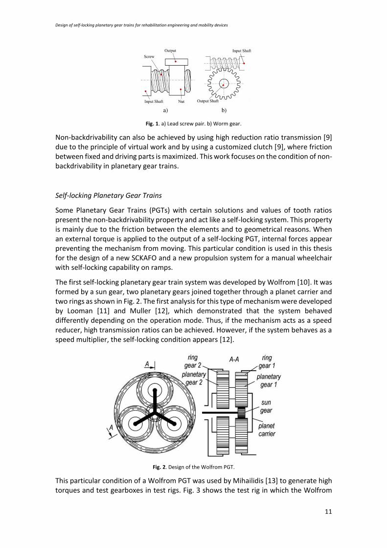
The existing mechanisms which have this property are lead-screws and worm drives [1,2], which are displayed in Fig. 1. These non-backdrivables mechanisms have been used on multiple occasions, above all in robotics, like the Southampton hand [3], CyberHand [4], RTR II [5] andTBM [6]. Worm gears have been particularly used in an active knee orthosis [7] and in a hip orthosis [8]. In these types of mechanisms, shear friction between gears acts as the brake force. The non-backdrivability of the mechanism is assured with a mechanical efficiency of less than 0.5 [2].
Design of self-locking planetary gear trains for rehabilitation engineering and mobility devices
11
Fig. 1. a) Lead screw pair. b) Worm gear.
Non-backdrivability can also be achieved by using high reduction ratio transmission [9] due to the principle of virtual work and by using a customized clutch [9], where friction between fixed and driving parts is maximized. This work focuses on the condition of non-backdrivability in planetary gear trains.
Self-locking Planetary Gear Trains
Some Planetary Gear Trains (PGTs) with certain solutions and values of tooth ratios present the non-backdrivability property and act like a self-locking system. This property is mainly due to the friction between the elements and to geometrical reasons. When an external torque is applied to the output of a self-locking PGT, internal forces appear preventing the mechanism from moving. This particular condition is used in this thesis for the design of a new SCKAFO and a new propulsion system for a manual wheelchair with self-locking capability on ramps.
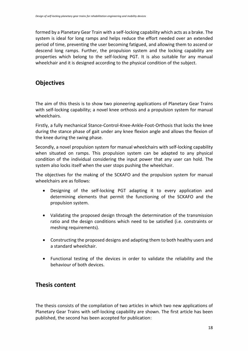
The first self-locking planetary gear train system was developed by Wolfrom [10]. It was formed by a sun gear, two planetary gears joined together through a planet carrier and two rings as shown in Fig. 2. The first analysis for this type of mechanism were developed by Looman [11] and Muller [12], which demonstrated that the system behaved differently depending on the operation mode. Thus, if the mechanism acts as a speed reducer, high transmission ratios can be achieved. However, if the system behaves as a speed multiplier, the self-locking condition appears [12].
Fig. 2. Design of the Wolfrom PGT.
This particular condition of a Wolfrom PGT was used by Mihailidis [13] to generate high torques and test gearboxes in test rigs. Fig. 3 shows the test rig in which the Wolfrom

Design of self-locking planetary gear trains for rehabilitation engineering and mobility devices
12
PGT is applied. It is evident that with small motors, high torques can be generated and the efficiencies of gearboxes can be calculated using these transmissions. When the main motor attemps to drive the output of the Wolfrom PGT, the self-locking condition appears and the PGT is locked without the usage of brakes. At this point, the stepper motor needs to drive the system and vary the torque or the system will rotate as a block.
Cesaroni [14] used a Wolfrom PGT at the output of the final wheel drive of electric trucks. Butsch [15], Orlowski [16] and Sulz [17] improved the Wolfrom PGT but no applications were carried out.
Fig. 3. Test rig using a Wolfrom PGT.
Other studies have been undertaken in order to determine the conditions for self-locking to appear [18] and also the efficiency of these transmissions [19-21]. Based on the literature, no application of self-locking planetary gear trains in the Biomechanics field was found.
On the contrary to other non-backdrivable mechanisms, self-locking PGTs are transmissions where the input and the output of the system are coaxial. This characteristic, together with the self-locking capability without any external brake or actuator, have allowed the use of self-locking PGTs to develop two fully mechanical devices with Biomechanical applications; a new SCKAFO and a new propulsion system for manual wheelchairs.
Stance-Control-Knee-Ankle-Foot-Orthosis
There are many SCKAFOS that use locking mechanisms to function, however, not many are completely mechanical. Having electrical or electronic components add more complexity to the control of the orthosis.
One of the first fully mechanical SCKAFOs was the Ottobock Bock Free Walk System [22] created by Becker Orthopædic UTX and presented in 1989 by Becker Orthopedic company. This system allows free flexion of the knee during the swing phase, and completely locks the knee during the stance phase. The main disadvantage of this orthosis is that the locking position is produced at full extension. Another disadvantage is that to switch between the stance phase and the swing phase, the user needs to produce a 10 degree dorsiflexion angle. The orthosis is presented in Fig. 4.

Design of self-locking planetary gear trains for rehabilitation engineering and mobility devices
13
Fig. 4. a) Assembly of the Ottobock Bock Free Walk System. b) Locked position. c) Unlocked position
Another fully mechanical SCKAFO was developed by Fillauer and called Fillauer Swing Phase Lock [22]. In this case, the locking and unlocking of the mechanism was activated by gravity using a weighted pawl. The system improved the previous activation method, however it only permitted a locking position between 0 and 10 degrees of knee flexion. The functioning of this orthosis is displayed in Fig. 5. With this SCKAFO, the knee is locked during the stance phase and moves freely during the swing phase.
Fig. 5. a) View of the Fillauer Swing Phase Lock. b) Locked position. c) Unlocked position.
The Horton Stance Control Orthosis [22] used another type of mechanism to control the locking of the knee. During heel strike, a pushrod pushes a cam and locks the orthosis due to the contact against a friction ring. Once the contact with the ground disappears, the user is able to flex the knee. The orthosis allows the locking of the knee at any flexion angle, however, an extension moment is required to switch between the locking position and the unlocking position. This device is displayed in Fig. 6.

Design of self-locking planetary gear trains for rehabilitation engineering and mobility devices
14
Fig. 6. a) View of the Horton Stance Control Orthosis. b) Locking mechanism.
A further fully mechanical SCKAFO was developed by Yakimovich et al. [22] which is able to both lock the knee at any flexion angle and permit the free rotation of the knee during the swing phase. The functioning of this orthosis is based on a belt that causes friction and thus increases the flexion resistance. Consequently, the joint locks. This orthosis is shown in Fig. 7 and although it controls the whole cycle of gait using a fully mechanical system, it requires a torsional torque to switch between the locking position and the unlocking position.
Fig. 7. a) Belt-clamping SCKAFO.
In [23] another SCKAFO is shown which allows the locking of the knee during the stance phase and allows the motion of the joint during the swing phase. The locking of the knee is achieved through a ratchet gear. This orthosis also allows the control of the flexion

Design of self-locking planetary gear trains for rehabilitation engineering and mobility devices
15
during the stance phase of up to 15 degrees. However, its functioning is limited to the adjustment of a mechanical timer before its usage which allows the switch between swing and stance phase. This mechanical timer obliges the user to follow a selected speed which must be maintained throughout the gait cycle.
Fig. 8. View of the SCKAFO [23].
A new SCKAFO which permits the control of knee during the stance phase and allows to move the knee during the swing phase is presented. The SCKAFO proposed in this work has the following characteristics:
• The system is fully mechanical, it does not require any electronical or electrical actuators or sensors for its functioning.
• The control of the orthosis depends exclusively on the movement of the user.
• The system self-locks at any knee flexion angle.
• A torque to switch between the locking and the unlocking position is not required.
• The SCKAFO allows free motion during the swing phase.
Propulsion system for manual wheelchairs with self-locking capability.
Most of the manual wheelchairs (about 90%) that exist on the market are pushrim propelled [24]. However, there are other propulsion methods that can help users to reduce the physiological impact that pushrim propelled wheelchairs produce. The following are the most common [24]:
• Crank propelled wheelchair: Uses a bicycle propulsion system to facilitate the propulsion of the wheelchair (Fig. 9 a)).
• Lever propelled wheelchair: It is designed with manually operated push levers that transfer force to the wheels through a transmission mechanism (Fig. 9 b)).

Design of self-locking planetary gear trains for rehabilitation engineering and mobility devices
16
• Hubcrank propelled wheelchair: The least common of the propulsion system, allows the user a continuous propulsion (Fig. 9 c)).
Fig. 9. a) Crank propelled. b) Lever propelled. c) Hubcrank propelled.
Each of these systems permits the adaptation of gear systems which facilitate the propulsion of manual wheelchairs during the climbing of steep ramps. A further issue to consider in manual wheelchairs users is the braking of the wheelchair. People with low mobility can find this very important above all when they are situated on ramps. The most common system to reduce the speed applies friction to the wheels. On many occasions and depending on the gravity of the injury, this task can be very difficult. Some of the most used braking systems are as follows:
• Shoe brakes: Their use is the most extensive and they are designed in a way that can be activated by pushing forward or pulling backwards (Fig. 10 a)).
• Scissor brakes: They are mostly used by active subjects in sporty environments (Fig. 10 c)).
• One-hand brakes: This option is used by patients with hemiplegia (Fig. 10 b)).
• Drum brakes: They are mainly used when the wheelchair is pushed by another person as they are normally located on the backrest (Fig. 10 d)).
Fig. 10. a) Shoe brake. b) One-hand brake. a) Scissor brake. b) Drum brake.

Design of self-locking planetary gear trains for rehabilitation engineering and mobility devices
17
All of these mechanisms require a manual activation and deactivation, which means that users must move or remove their hands in order to work the braking systems. However not all the mechanisms are manually activated, the system proposed in [25] is formed by a mechanical and automatic wheelchair brake which activates the brakes itself when a patient attempts to rise from the wheelchair (Fig. 11). The system consists of a three-way lever brake with three positions (locked, unlocked and automatic). There are other systems that automatically brake the wheels like those shown in [26, 27]
Fig. 11. a) Side view of the wheelchair. b) Three-mechanism.
As can be seen, there are many systems that are used to propel and brake a manual wheelchair. However, not many systems allow the user to both push the wheelchair and brake the system when required.
A system proposed by [28] whose commercial name is MagicWheel (Fig. 12), uses a geared transmission with a reduction mode which makes it suitable for climbing ramps. It also has a hill holding system which prevents the wheelchair from rolling backwards but the movement of the system is limited to the forward direction.
Fig. 12. a) View of the MagicWheels. b) Exploding view of the mechanism.
In this thesis, a propulsion geared system which can be attached to any manual wheelchair is proposed. The propulsion mechanism is fully mechanical and mainly
Design of self-locking planetary gear trains for rehabilitation engineering and mobility devices
18
formed by a Planetary Gear Train with a self-locking capability which acts as a brake. The system is ideal for long ramps and helps reduce the effort needed over an extended period of time, preventing the user becoming fatigued, and allowing them to ascend or descend long ramps. Further, the propulsion system and the locking capability are properties which belong to the self-locking PGT. It is also suitable for any manual wheelchair and it is designed according to the physical condition of the subject.
Objectives
The aim of this thesis is to show two pioneering applications of Planetary Gear Trains with self-locking capability; a novel knee orthosis and a propulsion system for manual wheelchairs.
Firstly, a fully mechanical Stance-Control-Knee-Ankle-Foot-Orthosis that locks the knee during the stance phase of gait under any knee flexion angle and allows the flexion of the knee during the swing phase.
Secondly, a novel propulsion system for manual wheelchairs with self-locking capability when situated on ramps. This propulsion system can be adapted to any physical condition of the individual considering the input power that any user can hold. The system also locks itself when the user stops pushing the wheelchair.
The objectives for the making of the SCKAFO and the propulsion system for manual wheelchairs are as follows:
• Designing of the self-locking PGT adapting it to every application and determining elements that permit the functioning of the SCKAFO and the propulsion system.
• Validating the proposed design through the determination of the transmission ratio and the design conditions which need to be satisfied (i.e. constraints or meshing requirements).
• Constructing the proposed designs and adapting them to both healthy users and a standard wheelchair.
• Functional testing of the devices in order to validate the reliability and the behaviour of both devices.
Thesis content
The thesis consists of the compilation of two articles in which two new applications of Planetary Gear Trains with self-locking capability are shown. The first article has been published, the second has been accepted for publication:

Design of self-locking planetary gear trains for rehabilitation engineering and mobility devices
19
• Jimenez GR, Salgado DR, Alonso FJ, del Castillo JM. A new stance control knee orthosis using a self-locking mechanism based on a planetary gear train. ASME. J. Mech. Des. 2018; doi:10.1115/1.4041780.
• Jimenez GR, Salgado DR, Alonso FJ, del Castillo JM. A new manual wheelchair propulsion system with self-locking capability on ramps, Mech. Sci., 9, 359-371, doi:10.5194/ms-9-359-2018, 2018.
Results and Discussion
The different applications proposed in this thesis are aimed at assisting the design of a fully mechanical SCKAFO and the design of a novel propulsion system with self-locking capability in manual wheelchairs. The results and further discussion of each device will be presented in the following paragraphs.
Stance-Control-Knee-Ankle-Foot-Orthosis
A new SCKAFO which can self-lock due to the actuation of a self-locking PGT has been built. The following steps show the construction of the orthosis:
• Design, evaluation and construction of a self-locking PGT with a transmission ratio of 1:12.
• Development of the three rods which complement the orthosis.
• Adaptation of the self-locking mechanism to a SCKAFO.
• Testing of the orthosis on two healthy subjects.
A two-stage Planetary Gear Train was built according to the equations proposed by [18] with a transmission ration of 1:12 and two multiplier stages were added in order to achieve a transmission ratio of 1:1 between the input and the output. Three rods were built and attached to the calf, the thigh and the output of the mechanism. The mission of the orthosis was to allow the motion during the swing phase of gait and self-lock during the stance phase. The rod attached to the output was also connected to the foot of the subject. During the stance phase, the contact with the ground produced a torque around the knee joint that locked the system and thus held the weight of the subject, allowing the user to continue walking. However, when contact with the ground (swing phase) was not made, the input of the system was done through the rod attached to the thigh, and so permitted the motion of the mechanism, allowing the user free swing until the contact with the ground was made again.
The SCKAFO was designed, built and tested on two healthy subjects in order to prove its functionality. The purpose of these trials was to demonstrate that the system self-locked during the stance phase, and allowed the user free swing during the swing phase.
The first trial was conducted on a healthy subject with 1.80 m of height and 80 kg of mass. The trial consisted of analysing the stance phase of the gait while walking at a preferred speed, and thus prove in a qualitative way that the device self-locked while load bearing. The trial proved that the orthosis permitted free swing during gait,

Design of self-locking planetary gear trains for rehabilitation engineering and mobility devices
20
allowing the user to move the joint freely. In this trial the device self-locked at an 8-degree knee flexion angle during the stance phase, which was maintained until contact with the ground terminated.
The same trial was tested on a different subject with 70 kg of mass and 1.80 m of height. The knee flexion angle during the stance phase was approximately 1 degree which was maintained while there was contact with the ground. The purpose of this trial was to analyse the behaviour of the SCKAFO on a further subject with different gait patterns.
Finally, a third trial was tested on the second subject, who was told to intentionally change the gait pattern, imitating a crouch gait. The aim of this trial was to demonstrate that the system self-locked in the presence of a different knee flexion angle while load bearing. During the swing phase the angles were higher than in the other two trials. Before heel strike (system self-locks) there was an angle of 34 degrees which remained the same during the stance phase.
The three trials demonstrated that system can be adapted to the gait of any user as the limitation in flexion knee angle is not given by the orthosis but the subject itself. The main component of the system was a PGT, which allowed any angle to be reached between the input and the output of the system. It was also demonstrated that the orthosis can self-lock at any knee flexion angle during the stance phase of gait. The only requirement for the self-locking to appear is that there is contact with the ground. If there is not such contact, the joint is free to move, and any angle (regarding the limitations of the subject) can be reached.
Both subjects felt comfortable while load bearing and felt less muscle effort due to the self-locking characteristic of the device, even during abnormal gait. During the swing phase no issues arose and thus the user was able to bend the knee comfortably since the output of the device was not in contact with the ground.
Propulsion system for manual wheelchairs
A new propulsion system with self-locking capability for manual wheelchairs has been built. The following steps show the construction of the propulsion system:
• Design, evaluation and construction of a self-locking PGT with a transmission ratio of 1:12.
• Assembly of a new multiplier stage which permits a transmission ratio of 5:12.
• Adaptation of the propulsion system to a standard manual wheelchair.
To prove the reliability of a self-locking system in manual wheelchairs, a prototype of a propulsion system has been made. In order to achieve the self-locking capability, the tooth ratios were calculated according to the equations shown in [18]. In this application, the transmission ratio achieved was also 1/12 as it is the maximum transmission ratio that a PGT must have to achieve such self-locking capability. A multiplier stage was added to the output of the self-locking stage to attain the desired transmission ratio of 5/12. The transmission was mounted underneath the seat of a standard wheelchair as it was the most adequate place for the purposes of the project.

Design of self-locking planetary gear trains for rehabilitation engineering and mobility devices
21
The housing of the mechanism is the fixed element and it is attached to the chassis of the wheelchair. An external pushrim was installed and connected to the input arm with the purpose of introducing power to the propulsion system and thus allowing the movement of the transmission.
The aim of this transmission is to allow the propulsion of the wheelchair when power is introduced by the external pushrim and also to self-lock when the power is introduced by the wheel. With this system the user does not need to activate or deactivate any external mechanism to brake the wheelchair when situated on a ramp. Furthermore, the effects of inertia when the user is on a ramp do not have to be overcome since the mechanism locks when power input is through the wheels.
The trials were conducted on a healthy subject with a height of 1.80m and a mass of 80 kg. The ramp used for the trials was located at the main entry of a residential area, it had a 10% slope and a length of 15 m. The first trial consisted of analysing the self-locking characteristic of the prototype.
The subject was told to remain stationary and not to move the external pushrim. While the subject was on the slope in an uphill direction the power input was transferred from the wheel to the output of the self-locking PGT, provoking the locking of the system and preventing the subject from rolling backwards. In the same way, when the subject was in a downhill direction, the prototype also self-locked. The subject was comfortable and did not feel any risk of rolling backwards or forwards while the prototype was locked. The first trial demonstrated that the system self-locked while the user was on a ramp without any power input.
The second trial consisted of introducing power through the external pushrim in order to test the motion of the prototype. By moving the external pushrim of the prototype, the power input was transferred from the external pushrim provoking the movement of the wheelchair. The subject was told to push the pushrim at the speed he considered appropriate. While pushing the wheelchair through various cycles and then halting the motion, the subject felt comfortable throughout the trial and did not feel at risk of rolling backwards or forwards. Further, the user did not feel the effects of inertia when changing between a stationary position and motion. This functioning prevented the user from rolling backwards while ascending or rolling downhill while descending. Further, the system moved while the power was introduced through the external rim allowing the user to ascend inclined ramps.
Conclusions
A new knee orthosis design encompassed within the group of SCKAFOs has been
presented. It consisted of a locking system which permitted the movement of the limb
during the swing phase and locked the knee joint during the stance phase. Three rods
were placed on the lower limb, one of which was fixed to the thigh of the user. The
second rod was connected to the calf and behaved as the input of the mechanism,
allowing power to be introduced during the swing phase. The third rod was anchored to

Design of self-locking planetary gear trains for rehabilitation engineering and mobility devices
22
the output of the mechanism and was responsible for introducing power through the
output during the stance phase, and hence caused the locking of the mechanism as
power could not be transmitted from the output.
Finally, it should be noted that unlike other orthoses designs proposed in the literature, this system is entirely mechanical. It therefore requires no electrical or electronic elements for its activation or deactivation. Additionally, it allows the knee to lock at any flexion angle during the stance phase and no torque is required to switch between the two phases of gait. These characteristics make this SCKAFO suitable for any subject, as the proposed design can be adapted to the gait of any user.
A new propulsion system used in manual wheelchairs to facilitate the ascending and descending on ramps was also designed and built. This transmission is based on a planetary gear train with self-locking capability. Due to the self-locking property, the transmission must be designed with a speed ratio lower than 1, making the device ideal for climbing ramps. The transmission is placed underneath the seat of the user, this allows that the chair maintains its dimensions regarding factors such as accessibility. The transmission shares both input and output axes which means that the system is coaxial. The input is connected to the new pushrim installed on a manual wheelchair and parallel to the wheel and its mission is to transmit power to the transmission. The output of the transmission is connected to the wheel. In this way, if the user introduces power through the new pushrim, the system will move the wheel. However, if the movement is introduced through the wheel, the system will self-lock due to the lack of power transmission in this direction. This system can be adapted to any physical condition (measured by the amount of power which each person can apply over a long period time) of the user. The transmission ratio is adapted to the physical condition of the user and the slope which is going to be ascended.
The system is formed by only mechanical components and no electronic or electrical actuator is required, it does not need any external elements for its activation/deactivation. This permits the user to push the wheelchair without fearing unexpected descending. These factors make this system suitable for every manual wheelchair user.
Finally, for future works, this type of self-locking transmission could have further applications in other types of vehicles such as bicycles and its usage could even be extended to transport and handling systems such as hoists. In the latter, the traditional transmission system could be modified with a self-locking PGT in order to lift heavy weights.
Design of self-locking planetary gear trains for rehabilitation engineering and mobility devices
23
References
[1] Plooij, G. Mathijssen, P. Cherelle, D. Lefeber and B. Vanderborght, "Lock Your Robot: A Review of Locking Devices in Robotics," in IEEE Robotics & Automation Magazine, vol. 22, no. 1, pp. 106-117, March 2015. doi: 10.1109/MRA.2014.2381368.
[2] M. Controzzi, et al., Miniaturized non-back-drivable mechanism for robotic applications, Mech.Mach. Theory 10(10):1395-1406 doi: 10.1016/j.mechmachtheory.2010.05.008.
[3] C.M. Light, P.H. Chappell, Development of a lightweight and adaptable multiple-axis hand prosthesis, Medical Engineering & Physics 22 (2000) 679–684. DOI: https://doi.org/10.1016/S1350-4533(01)00017-0.
[4] M.C. Carrozza, G. Cappiello, S. Micera, B.B. Edin, L. Beccai, C. Cipriani, Design of a cybernetic hand for perception and action, Biological Cybernetics 95 (6) (2006) 629–644. DOI: 10.1007/s00422-006-0124-2.
[5] B. Massa, S. Roccella, M. C. Carrozza and P. Dario, "Design and development of
an underactuated prosthetic hand," Proceedings 2002 IEEE International Conference on Robotics and Automation (Cat. No.02CH37292), Washington, DC, USA, 2002, pp. 3374-3379 vol.4. doi: 10.1109/ROBOT.2002.1014232
[6] N. Dechev, W.L. Cleghorn, S. Naumann, Multiple finger, passive adaptive grasp prosthetic hand, Mechanism and Machine Theory 36 (10) (2001) 1157–1173. doi: 10.1016/S0094-114X(01)00035-0.
[7] Wilian M. dos Santos, Glauco A.P. Caurin, Adriano A.G. Siqueira. Design and
control of an active knee orthosis driven by a rotary Series Elastic Actuator Control Engineering Practice 58 (2017) 307–318. doi: 10.1016/j.conengprac.2015.09.008.
[8] Olivier, J., Ortlieb, A., Bouri, M., & Bleuler, H. (2015). Mechanisms for actuated
assistive hip orthoses. Robotics and Autonomous Systems, 73, 59-67. DOI:10.1016/j.robot.2014.10.002.
[9] In, H., Kang, S., & Cho, K. (2012). Capstan brake: Passive brake for tendon-driven
mechanism. 2012 IEEE/RSJ International Conference on Intelligent Robots and Systems, 2301-2306.
[10] Wolfrom, U., Der Wirkungsgrad von Planetengetrieben. Werkstatttechnik. 1912.
p. 615-617.

Design of self-locking planetary gear trains for rehabilitation engineering and mobility devices
24
[11] Loomann J. Zahnradgetriebe: Grundlagen, Konstruktionen, Anwendungen in Fahrzeugen. Springer Berlin Heidelberg: New York 1996.
[12] Müller HW. Die Umlaufgetriebe. Auslegung und vielseitige [13] Athanassios Mihailidis and Ioannis Nerantzis, “ A New System for Testing Gears
Under Variable Torque and Speed”, Recent Patents on Mechanical Engineering (2009) 2: 179. https://doi.org/10.2174/2212797610902030179.
[14] Cesaroni, A.F.: An imbricate type epicyclic reduction gear. Italy Pat. App. Publ.
EP1396660A2, 2003. [15] Butsch, M., Eisele, F., Fries, U.: Spielarmes Wolfrom-Planetenzahnradgetriebe,
Germany Pat. App. Publ. EP0678688 A1, 1994. [16] Orlowski, B.: Wolfrom-Planetenzahnradgetriebe mit axial in zwei unterschiedlich
verzahnte Bereiche aufgeteilten Planetenrädern, Germany Pat. App. Publ. EP0627575 B1,1994.
[17] Schulz, H.: Planetengetriebe, Germany Pat. App. Publ 19928385, 2000. [18] D.R. Salgado, J.M. del Castillo, Conditions for self-locking in planetary gear trains.
J Mech Des Trans J. Mech. (2006) 960-968. doi:10.1115/1.2748449. [19] Ikejo K, Nagamura K, Yada T, Kagari Y. Self-Locking of 2S-C Type Planetary Gear
Train Composed of External Gears. ASME. International Design Engineering Technical Conferences and Computers and Information in Engineering Conference (2009) 39-46. doi:10.1115/DETC2009-86291.
[20] Jose M. del Castillo, The analytical expression of the efficiency of planetary gear
trains, Mechanism and Machine Theory, Volume 37, Issue 2, 2002, Pages 197-214, ISSN 0094-114X, doi:10.1016/S0094-114X(01)00077-5.
[21] Karaivanov, D; Troha, S.; Pavlova, R. Investigation into self-locking planetary gear
trains through the lever analogy. Transactions of FAMENA. 2012, Vol. 36 Issue 1, p13-24.
[22] Yakimovich, T., J. Kofman, and E. D. Lemaire. Engineering design review of
stance-control knee-ankle-foot orthoses. Journal of Rehab Res and Dev. Vol 46, Number 2, 2009, 257-268. DOI: 10.1682/JRRD.2008.02.0024.
[23] Andrysek J, Leineweber MJ, Lee H. Development and Evaluation of a Mechanical
Stance-Controlled Orthotic Knee Joint With Stance Flexion. ASME. J. Mech. Des. 2017;139(3):035001-035001-7. doi:10.1115/1.4035372.

Design of self-locking planetary gear trains for rehabilitation engineering and mobility devices
25
[24] van der Woude LHV, Dallmeijer AJ, Janssen TWJ, et al: Alternative modes of manual wheelchair ambulation: An overview. Am J Phys Med Rehabil 2001;80:765–777.
[25] Babilas J., Automatic Wheel chair brake, United States App. Publ: 4,623,043,
1986. [26] Dugas G.A, Automatic braking wheelchair, United States App. Publ: 5,984,334,
1999. [27] Melvin G. Hector, Jr., Tucson, Structure, components and method for
constructing and operating an automatically self locking manually propelled vehicle such asa wheel chair, United States App. Publ: US 8,622.409 B2, 2014.
[28] Meginniss, S. M. and SanFrancisco, A. S.: Two-Speed manual wheelchair wheel,
United States Pat. Appl. Publ., 53, US 2006/0197302 A1, 2006.

Design of self-locking planetary gear trains for rehabilitation engineering and mobility devices
26
Appendix The main content of this thesis is based on the following journal papers.
• Jimenez GR, Salgado DR, Alonso FJ, del Castillo JM. A new stance control knee orthosis using a self-locking mechanism based on a planetary gear train. ASME. J. Mech. Des. 2018; doi:10.1115/1.4041780. (Accepted for publication)
• Jimenez GR, Salgado DR, Alonso FJ, del Castillo JM. A new manual wheelchair propulsion system with self-locking capability on ramps, Mech. Sci., 9, 359-371, doi:10.5194/ms-9-359-2018, 2018. (Published)
A complete copy of each paper is shown in the following pages.

A new stance control knee orthosis using a self-locking mechanism based on a planetary gear train
G. R. Jiménez1, D. R. Salgado1, F. J. Alonso1, J.M. del Castillo2
1Department of Mechanical, Energy and Materials Engineering. University of Extremadura. [email protected]; {drs, fjas}@unex.es
2Department of Material Science and Transportation Engineering. University of Seville.; [email protected]
Abstract
The objective of this work was to design and build a fully mechanical knee orthosis. A knee orthosis should both allow control of the angle of flexion of the knee during the stance phase of the gait cycle and leave the joint free during the swing phase. Knee orthoses are normally used to assist the walking of people suffering from muscle weaknesses or gait pathologies in order to avoid excessive knee flexion during the stance phase. The design of the orthosis proposed in the present work is characterized by allowing the knee to be locked at any angle of flexion during the stance phase, and because the orthosis can be unlocked to allow the joint to be released in the swing phase without the action of any external agent, i.e., without requiring external electrical or electronic systems for the control and performance of the orthosis. These characteristics mean that the design can be adapted to the gait of any user. The proposed design consists of a set of three rods, one attached to the user’s thigh, another to the calf, and the other to the foot, connected to each other by a self-locking planetary gear train (PGT). [DOI: 10.1115/1.4041780]
Keywords: orthoses; rehabilitation engineering; knee locking system; self-locking planetary gear train; stance control.
1. Introduction
There are numerous potential causes of muscle weakness. These include post-polio syndrome, spinal cord injury, trauma, multiple sclerosis, muscular dystrophy, unilateral leg paralysis, and paresis [1]. Sufferers usually need a passive or active orthosis to help them lock the knee while walking. Many of the orthoses currently available on the market are mainly used in rehabilitation [2-5] or to improve control of the ankle joint [6-8] or knee [9-14]. They can be classified into three distinct groups: passive knee-ankle-foot-orthoses (KAFOs), stance control KAFOs (SCKAFOs), and dynamic KAFOs.
Passive KAFOs act without any external power source. Most of them lock the knee during both the stance and the swing phases. The knee remains blocked resulting in an uncomfortable gait requiring high energy consumption [1] on the user's part. This leads many of these patients (more than 60%) to stop using them [12]. There are various types of locking systems used in these orthoses: ratchet lock, drop lock, bail lock, and dial lock. However, they all have the disadvantage that they can not be locked at any, not predetermined, angle of flexion [11], i.e., they only allow blockage in certain joint positions, which makes their use less comfortable and less adaptable to each user.
The second group, SCKAFOs, are orthoses that lock the knee during the stance phase and
allow knee flexion during the swing phase of gait. Not all SCKAFOs block at any angle of knee
flexion, and those that do, such as the Quasi-Passive Compliant Stance Control Knee-Ankle-
Foot Orthosis [12], use sensors to electronically control their action. These orthoses improve
gait control relative to passive KAFOs. In addition, they can reduce gait compensations and

allow patients to walk with less effort [1]. They have been studied and improved extensively
due to their great reliability. There remain, however, certain abnormal patterns during gait due
to knee blockage in the stance phase [11]. They use a great diversity of locking mechanisms.
Some examples are ratchets, cams, friction mechanisms, hydraulic mechanisms, and
magnetically activated clutches. The orthosis proposed in the present paper belongs to the
SCKAFO family because the control of gait is established in the stance phase, and released
during the swing phase.
Dynamic KAFOs reproduce the user's normal gait more accurately than the foregoing
orthoses since they implement a system of control of the different moments/movements that
constitute the various phases of gait. They allow the knee to be locked at any flexion angle
during gait, and hence allow control of the complete gait cycle whether in the stance phase or
in the swing phase. They are bulkier than other orthoses because they necessarily require a
sensor, actuation, and control system and a battery. Different types of mechanisms are
implemented to perform the blocking during the stance phase. These include spring
mechanisms [13], a pneumatic system [14], a hydraulic system [11], and a combination of
superelastic rods and springs [11]. Although orthoses of this type can simulate gait correctly,
they are not completely mechanical solutions like the one proposed here. Moreover, their
complex control system means that they are mainly used as laboratory rehabilitation devices
[11].
The orthosis proposed here is characterized by allowing the knee to be locked at any
flexion/extension angle during the stance phase, and because it can be unlocked to release the
joint in the swing phase without the action of any external agent, i.e., without requiring
external electrical or electronic systems. It is therefore a fully mechanical design, classifiable as
an SCKAFO as indicated above.
The objective of the present work was to design and build a new SCKAFO type knee orthosis
that adapts adequately to any user's gait, regardless of the angle of flexion during stance. It
requires no external control system. Instead, control is carried out directly in response to the
user's own movements, as we shall detail below. The design consists of a set of three rods or
bars, one attached to the thigh, one to the calf, and one to the foot, connected to each other
by a self-locking planetary gear train (PGT).
The paper is organized as follows. Section 2 describes the locking mechanisms used. Section
3 presents the design of the proposed mechanical SCKAFO based on a self-locking PGT. Section
4 the validation of the proposed design and Section 5 shows the functional and qualitative
evaluation of the device. Finally, Section 6 presents the conclusions and future works.
2. Locking mechanisms used in orthoses design
There are various knee locking systems, whether for control in the stance phase, in the
swing phase, or both. However, very few of them are fully mechanical, i.e., not requiring
sensors, actuators, electrical systems, etc. In the present work, only mechanical locking
systems that do not require any type of actuation are analysed. In particular, we shall not
include the blocking mechanisms of Dynamic KAFOs. The following are some of the
mechanisms implemented in Passive KAFOs and SCKAFOs.
Fig. 1 shows a ratchet lock system used in a Passive KAFO. This system does not allow knee

locking in all positions. It is used to facilitate the patient's standing from a sitting position to an
upright position. To this end, the mechanism has a locking system that varies every 12° until
the full extension of the knee, thus avoiding knee flexion. To unlock the system (flex the knee),
it is necessary to manually press a lever.
Fig. 1. Ratchet lock locking mechanism.
The dial lock mechanism shown in Fig. 2 is another example of a locking mechanism
used in the design of Passive KAFOs. This system only allows a pre-configured locking position.
By using a dial, the subject can choose the desired locking position, and the system will then
allow knee flexion to the chosen angle. This type of mechanism is most frequently used for
rehabilitation.
Fig. 2. Locking system based on a dial lock.
Fig. 3 shows the Ottobock Bock Free Walk System created by Becker Orthopædic UTX [15].
This system allows free flexion of the knee during the swing phase, and completely blocks the
knee during the stance phase. It remains locked unless the ankle produces a dorsiflexion of 10°.
At this point, the locking system disengages and the knee can again move freely during the

swing phase.
Fig. 3. Ottobock Free Walk/Becker Orthopædic UTX. Spring loaded mechanism. Image obtained from [19]
Fig. 4 shows the Fillauer Swing KAFO system [15]. This employs a mechanical locking
system in which a pawl moves under gravity. This device locks the knee during the stance
phase and the knee moves freely during the swing phase. It locks in full extension of the knee,
so that there is only one locking position. Release does not occur automatically but depends
on the angle of hip flexion. Fig. 4(a) shows the behaviour of the system under complete knee
extension when the thigh is anterior to the individual's body, and Fig. 4(b) when the thigh is
posterior to the body, when the pawl falls out of engagement.
Fig. 4. Fillauer swing KAFO [19] showing the behaviour of the orthosis in different situations.
Another locking solution is belt-clamping [15] (Fig. 5(a)). This system works by friction.
The belt attaches to the upper and lower supports and extends through the knee shaft. The
resulting flexural strength increases as the knee flexes [16] allowing locking of the knee joint.

The tension decreases with extension of the knee at any time. This system requires rods along
the medial and lateral zones of the leg to operate (Fig. 5(b)).
Fig. 5. Belt-Clamping SCKAFO. a) Components of the SCKAFO. b) Two views of the orthosis. Image obtained from [20].
The various mechanical locking systems currently used in orthotic design are
summarized in Table 1. The last row of the table corresponds to the locking mechanism of our
proposed new orthosis design.
Table 1. Characteristics of mechanical locking systems in orthoses.
Name Type Condition of the knee
joint during the gait cycle
Locking Position Unlocking mechanism
Ratchet lock Passive KAFO
The knee extends freely but flexion is blocked during the entire gait
cycle
Every 12 degrees until full extension
Knee flexion is blocked automatically due to the ratchet lock. The knee is
unlocked by pressing down the release lever of the
ratchet lock
Dial lock Passive KAFO The knee is locked during
the entire gait cycle At any specified
knee flexion angle
The knee locks automatically when
extending. It is unlocked by pulling up
the dial of the KAFO
Otto Bock Free Walk Becker Orthopaedic
UTX. SCKAFO
The knee is locked in stance and moves
freely in swing Full extension
10 degrees ankle Dorsiflexion to pull down And disengage the lock
Fillauer swing KAFO SCKAFO The knee is locked in
stance and moves freely in swing
From 0 to 10 degrees of knee flexion
Automatically
Belt-clamping SCKAFO The knee is locked in
stance and moves freely in swing
Any knee flexion angle at heel strike
Automatically
Proposed knee-locking system
SCKAFO The knee is locked in
stance and moves freely in swing
Any knee flexion angle at foot strike
Automatically

All of the mechanisms discussed above except the one proposed in this paper require an
unlocking torque for the transition between the locked and the unlocked phases. In the
mechanism proposed in this work, unlocking occurs automatically, and the patient does not
need to perform any extra movement to disable the block during the stance phase. They
simply have to maintain their own walking pattern for the correct functioning of the orthosis.
In addition, the locking occurs at any knee flexion angle, and does not need any part that
affects the mechanism in the medial zone of the leg. In the following, we shall divide our
explanation of the design into three parts. First, we shall describe the proposed blocking
mechanism, explaining how the system is arranged for its proper operation. Second, we shall
discuss the different possible construction solutions and the tooth ratios needed for self-
locking to occur. Third, a dynamic analysis will be included to verify the viability of the chosen
solution. And fourth, a qualitative study of a prototype built will be tested on a healthy subject
to analyse the self-locking condition.
3. Design of the orthosis based on a self-locking Planetary Gear Train
The proposed orthosis design consists of two parts: a locking system based on a self-locking planetary gear train, and a set of three rods or bars. Each of these rods has a specific function, and is attached to one member of the PGT and to different parts of the leg. In particular, one rod is attached to the thigh (Rod 1), another to the calf (Rod 2), and the other to the foot (Rod 3). They are connected to each other by a self-locking planetary gear train. An outline of this design is shown in Fig. 6.
As can be seen in the Fig. 6(a), Rod 1 is attached to the thigh, and is anchored in position to the PGT's housing, i.e., to the fixed member of that transmission (see Fig. 6(c)). Rods 2 and 3 are attached to the PGT's input and output axes.

Fig. 6. a) and b) Two views of the solution for the construction of the SCKAFO design (rods and self-locking mechanism in relation to the limb). c) Schematic diagram of the proposed SCKAFO design.
The task of Rod 1 is to support the orthosis, and to serve as the element establishing the fixed member of the transmission, i.e., the member whose angular velocity with respect to the thigh is zero. Rod 2 is attached to the calf and the PGT's input. It is this rod which allows power to be input during the swing phase, i.e., when the system is not blocked. Rod 3 is connected to the PGT's output. Its mission is to allow the orthosis to block during the stance phase when the foot comes into contact with the ground. This is because power input to the transmission in the stance phase is through this rod, and in this sense the transmission does not let power flow towards Rod 2, so it is self-locking by causing Rods 1 and 3 to be fixed in place in this phase of the gait cycle. The knee locking system implemented in this design allows the knee to flex and to extend during the swing phase regardless of the angle of flexion of the knee.
Fig. 7 shows how the locking mechanism acts during gait. At the beginning of the gait cycle, the foot (Rod 3) makes contact with the ground (initial contact). As a result of this, a reaction occurs which results in a resistant torque (To) in the knee that impedes the knee's flexion. This torque is produced at the output of the mechanical device (Rod 3), and causes the PGT to self-lock when attempting to send power from Rod 3 to Rod 2. Thus, the knee remains locked during the sub-phases of stance, i.e., loading response, mid stance, terminal stance, and pre-swing (see Fig. 7) since the position of Rod 3 relative to Rod 1 stays fixed. When the user enters the swing phase in the initial swing, there is no longer any contact with the ground. So the input torque on the locking mechanism, Ti, is produced by the rotation of the calf (Rod 2) with respect to the thigh (Rod 1). This torque causes power flow in the PGT to be from Rod 2 to Rod 3, i.e., in the direction for which the PGT does not self-lock and therefore allows movement. In particular, the transmission allows the movement Rod 3 in phase with Rod 2 during mid swing and terminal swing, until the foot again comes into contact with the ground, and the cycle is repeated.
Fig. 7. Performance of the knee locking system during different stages of gait.

With respect to the design of the transmission implemented in the orthosis, in the swing phase, Rods 2 and 3 need to have the same angular velocity relative to the fixed member (thigh), and therefore the design must have a transmission ratio equal to unity. However, it has been shown [16] that the transmission ratio of a self-locking PGT has to be less than unity, i.e., it has to be designed as a speed reducer. Therefore, in order to obtain a transmission ratio of unity between Rods 2 and 3 of the orthosis, it is necessary to include another planetary transmission in series with the self-locking PGT that multiplies the speed so as to obtain a final transmission ratio equal to unity. Fig. 8 is a schematic diagram of such an orthotic locking system consisting of a speed reducer self-locking PGT with a speed multiplier PGT that can result in an overall transmission ratio of unity.
Fig. 8. Parts of the knee locking system.
4. Validation of the proposed orthosis design
In this section a solution will be determined for the construction of the proposed orthosis,
in particular, for the knee locking system shown in Fig. 8. For a PGT to be self-locking, it must
satisfy a series of design conditions that allow only a reduced set of constructional solutions
[16].
For simplicity of construction, we considered the two 4-member self-locking PGT solutions,
since these have the fewest members. These two solutions are shown in Fig. 9. We chose to
analyse the one shown in Fig. 9(a) because it has external (gear/gear) pairs rather than internal
(gear/ring-gear) pairs. For this solution to be self-locking, the following expression must be
satisfied:
𝜂14𝜂24 <𝑍24
𝑍14<
1
𝜂14𝜂24 (1)
where 𝜂𝑖𝑗 is the ordinary efficiencies of the circuits of the PGT. The ordinary efficiency is the
efficiency of the gear pair if the arm linked to the planet were fixed. By means of this
efficiency, one introduces into the overall efficiency calculation of the gear train the friction

losses that take place in each gear pair. Although the value of the ordinary efficiency in each
gear pair depends on the number of teeth of its gears, on the operating conditions (applied
torque, speed, lubricant type and method, temperature), and on geometric factors such as the
approach portion and the recess portion and on tooth surface roughness [17-19], for the
analysis of the self-locking conditions; it is sufficient to consider a value of the ordinary
efficiencies slightly less than unity [16]. In Eq. (1) 𝑍𝑖𝑗 is the tooth ratio of the gear pair formed
by the linking members i and j. In particular, 𝑍𝑖𝑗 is defined as 𝑍𝑖𝑗=𝑍𝑖 𝑍𝑗⁄ . For the definition of
the tooth ratios to satisfy the Willis equations, 𝑍𝑖𝑗 must be positive if the gear is external
(meshing gear–gear) and negative if it is internal (meshing ring gear–gear). For the train of Fig.
9(a), one would have to take 𝑍14 > 0 and 𝑍24 > 0.
Fig. 9. Constructional solutions for 4-member planetary gear trains.
The two solutions for a 4-member self-locking PGT shown in Fig. 9 only allow power
flow with input through the arm (Member 3) and output through the sun (Member 1), as
indicated by the arrow in the Fig. 9. The transmission ratio of such 4-member PGTs with arm
input is [20]:
𝑟 =𝑍14−𝑍24
𝑍14 (2)
The constraints on the design of an orthotic locking system based on PGTs can be
grouped into those involving size and geometry, as will be and those involving meshing
requirements. These two groups will be detailed below.
Constraints involving gear size and geometry
The first constraint is a practical limitation of the range for the acceptable face width b.
This constraint is as follows:

9𝑚 < 𝑏 < 14𝑚 (3)
Where 𝑚 is the module of the gear. All of the kinematic and dynamic parameters of the
transmission depend on the values of the tooth ratios 𝑍𝑖𝑗. In theory, the tooth ratios can take
any value, but in practice, they are limited mainly for technical reasons because of the
difficulty in assembling gears outside of a certain range of tooth ratios. In this work, the tooth
ratio for the design of mechanical spindle speeders are quite close to the recommendations of
Müller [17] and the American Gear Manufacturers Association (AGMA) norm [20], and are:
0.2 < 𝑍𝑖𝑗 < 5 (4)
−7 < 𝑍𝑖𝑗 < −2.2 (5)
with the constraint given by Eq. (4) being for external gears and that by Eq. (5) for internal
gears. It is important to note that these constraints are valid for designs with different
numbers of planets (Np) [17].
Another constraint that will be imposed on the design of four-PGT with double planets, as the
self-locking PGT implemented in the orthosis design, is that the ratio of the diameters of the
gears constituting a double planet [20] is shown in the below equation:
1
3<
𝑑4
𝑑4′< 3 (6)
where d4 and d4’ are the diameter of the gears than constitutes the planet gear that meshes
with members 1 and 2 (see Fig. 9).
Planetary gear train meshing requirements
The meshing requirements are given by the AGMA norm [20]. For planetary systems
with double planets must, either of which, factorise with the number of planets in the sense of
Eq. 7 below (see AGMA norm [20]):
𝑍2𝑃2±𝑍1𝑃1
𝑁𝑝= 𝑎𝑛 𝑖𝑛𝑡𝑒𝑔𝑒𝑟 (7)
where P1 and P2 are the numerator and denominator of the irreducible fraction equivalent to
the fraction 𝑍4′ 𝑍4⁄ ; where 𝑍4′ is the number of teeth of the planet gear that meshes with
member 1 and Z4 is the number of teeth of the planet gear that meshes with member 2 (see
Fig. 9):
𝑍4′
𝑍4=
𝑃1
𝑃2 (8)
In order to satisfy the above requirements, and since the 4-member PGT with an input
arm is a reduction transmission, the maximum transmission ratio that can be achieved in order
to obtain a self-locking train, i.e., Eq. 1, and which also satisfies the above conditions (Eqs. (2-
8)), is 𝑟 = 1 12⁄ . This maximum possible transmission ratio was chosen since, as indicated
previously, the transmission ratio between Rods 2 and 3 must be unity, and hence less
multiplication will need to be implemented at a later stage.
As a specific design proposal, we propose the following teeth numbers for the self-
locking PGT of Fig. 9(a):

𝑍1 = 21 𝑍2 = 21 𝑍4 = 24 𝑍4′ = 22
and a planet composed of three gears (Np = 3), as shown in Fig. 10.
Fig. 10. Assembly of the self-locking PGT. The arrows of ωin and ωout represent the direction in which the PGT transmits power.
For the speed multiplier, we chose a two-stage design because, as will be explained
below, the transmission will have to bear high loads, and a single stage multiplier would mean
that the complete mechanism would be of a larger diameter. The two multipliers implemented
are of ×3 and ×4 multiplication ratios (Fig. 11(a)).

Fig. 11. a) A scheme of the complete transmission mechanism implemented between Rods 2 and 3 of the orthosis.
b) Dimensions (in mm) of the mechanism (for a person of 80 kg mass, the knee supports 52 Nm).
To size the transmission mechanism between Rods 2 and 3 of the orthosis, we determined the torques that the system must support during the stance and swing phases.
In the stance phase, the torque transmitted to the transmission is the knee-locking torque required to prevent thigh-calf flexion and that is triggered by a reaction force at the initiation of that phase. In the literature, this torque is clearly defined for the gait cycle [11, 14], and depends on the subject's weight. One sees in Fig. 12 that the maximum torque produced in the knee during the stance phase is approximately 0.65 Nm/kg. Hence, for an average person of 80 kg mass, the knee supports 52 Nm.
During the swing phase, the torques produced in the knee are smaller than during the stance phase. Power recirculation occurs when the power that is transmitted by a gear pair is greater than the input power. This phenomenon appears in self-locking PGT [16]. However, as can be seen in Fig. 12 the torques produced around the knee during the swing phase are very low compared to the stance phase, so this phenomenon does not significantly affect the device. Even in these cases, however, because the power that the subject inputs in the swing phase is relatively low, the torques that the gears must support are smaller than in the stance phase. The torques in the swing phase were calculated using the expressions given in Refs. [16] and [21]. In sum therefore, the locking system must be designed to withstand the stresses that occur during the stance phase, since this is the more restrictive.
Fig. 12. Knee torques during a gait cycle.
The representation of the dynamic loads on the cogs of the gears was calculated using
CAE tools. It is very difficult with this type of tool to calculate the power recirculation that
occurs in the self-locking PGT when the system is in motion. As noted above, however, the
stage with the greatest torques in the gears is when the mechanism is blocked in the stance
phase. Table 2 lists the characteristics of the gears in the complete self-locking PGT and
planetary multiplier system.

Table 2.
Characteristics of all the gears that form the self-locking PGT with the multipliers. rp: pitch radius in mm, ra:
addendum radius in mm, rd: deddendum radius in mm, α: pressure angle, m: module in mm, t: thickness in mm, Rc: Ratio contact (x3) Due to the number of planets.
Member Teeth Distance Centres
(mm)
rp (mm)
ra (mm)
rd (mm)
α m
(mm) t
(mm) Rc
(x3)
Self-locking PGT
2 21
32.25
15.01 16.44 13.58
20
1.43 6 1.58
4 24 17.16 18.59 15.73 1.43
1 21 15.75 17.25 14.25 1.5 6 1.57
4' 22 16.5 18 15 1.5
Multiplier x3
Ring 80
51
68 66.7 69.7
20
1.7
3 4.47
1.63
Planet 40 34 35.7 32.3 1.7
Sun 20 17 18.7 15.3 1.7
Multiplier x4
Ring 90
45
67.5 66 69
20
1.5
3 5.39
1.65
Planet 30 22.5 24 21 1.5
Sun 30 22.5 24 21 1.5
The housing in which the self-locking system is located is made of plastic. This material will
hold the produced efforts due to the self-locking and will not affect in excess the weight of the
device. The gears are made of steel with an elastic limit 𝜎 =241.27MPa. The rods are made of
duraluminum. The torque produced by the locking of the system is known and fixed for each
individual’s gait, and must be supported by the complete system. This allows the locking
system to be designed with acceptable dimensions taking the stresses between the cogs in
contact into account. The contact ratios between the pairs of gears are high, and will allow the
forces to be distributed over more points of contact, with consequently lower tangential forces
on each zone of contact. From the data in Table 2, one sees that the suns (1 and 2) are the
members of the PGT with smallest radii. Planets 4 and 40, forming the same member, share
the supported torque between the two of them.
Fig. 13. a) Stresses produced by the tangential forces applied to the cog during the blocking phase. b) Areas in which the different contacts occur, and the application of the tangential force produced by the contact in the least favourable area.
Thus, the input and output members (1 and 2) of the self-locking PGT will be those that bear
the most load. The method used to calculate the resistance of the mechanism is that described

in Refs. [21–24]. In particular, as illustrated in Fig. 13(a) for gear 2, the contact between two
gears was simulated applying the tangential force caused by the torque to the center of the
gear at the primitive radius, distributed over the thickness of the cog. Regarding the boundary
conditions the gear is fixed in the center simulating the self-locking condition. The contact
force is simulated as shown in Fig. 13(b). The results showed that the teeth of the gear indeed
support the stresses generated. The different parts of the locking mechanism and their
approximate dimensions that will allow the stresses produced during the stance phase to be
supported are shown in Fig. 11(b). The length of the arms that connect the different stages of
the mechanism was taken to be 10mm. All the elements designed in the knee lock system are
straightcut gears. The mechanism’s volume could be reduced if gears were used since the
contact ratio between each gear pair would be greater, and hence the forces would be
distributed over more points of contact. We decided to use straight cut gears for the present
work because the speeds to which the system will be subjected are not high, and the
manufacturing costs would be lower.
5. Functional and qualitative evaluation
In this work a prototype of the SCKAFO has been tested in order to validate the reliability and
the behaviour of the device during the stance phase of gait. For the purpose of the trial, the
prototype was built using medial and lateral support for both Rods 1 and 2. The third bar (Rod
3) was built in aluminum and attached to the output of the device. An insole was fixed to Rod 3
and its goal is to make contact with the ground. In Fig. 14, the complete proposed device is
shown in a) front view and b) sagittal view.
Fig. 14. a) Front view of the prototype built. b) Sagital view.
The first trial was conducted on a healthy subject with 1.80 m of height and 80 kg of mass
(subject1). It consisted of analysing the stance phase of the gait while walking at a preferred
speed, and prove in a qualitative way that the device self-locks while load bearing. Fig. 15 (a)
shows different stages of gait during the stance phase and the swing phase.

The second trial was conducted on a new healthy subject with 70 kg of mass and 1.80 m of
height (subject 2). Following the considerations of the previous trial, an analysis of the
behavior of the orthosis was carried out in another subject.
The third trial (Fig. 15(c)) was analyzed on subject 2. In this case, the subject was told to
maintain the knee flexion in order to imitate the crouch gait. The purpose of this trial is to
demonstrate that the system self-locks in the presence of a different knee flexion angle while
foot contact.
Being the main component of the device a self-locking PGT, any angle can be achieved
between the input–output (rod 2–rod 3) and the fixed member (rod 1). The system adapts to
any user’s gait and the limitation in angle will be given by the gait limitation of the user. In Fig.
15 the knee angles during gait are shown for every subject. To measure the knee angle during
both stance and swing phase, two lines were traced on the photograms of Fig. 15 representing
rod 1 and rod 3 and the angle between these lines was calculated. During the swing phase two
photograms of the cycle for each trials are shown, which represent initial swing and terminal
swing, respectively. Variable a represents the angle between rod 1 and rod 3. During the
stance phase, three photo grams of the cycle are shown.
It is evident that during the stance phase in all of the trials, the relative angle between rods 2-3
and rod 1 remains the same since there is a force contact with the ground, and under this
condition the device is locked. However, when the contact with the ground finishes, the joint is
free to move and the flexion of the knee occurs.

Fig. 15. Testing of the device on two healthy subjects: (a) normal cycle of gait on subject 1, (b) normal cycle of gait of subject 2, and (c) simulated crouch gait of subject 2
Different repetitions of every trial consisting of three or four steps for every gait cycle were
carried out. Both users felt comfortable while load bearing and could feel less muscle effort
due to the self-locking characteristic of the device even during an abnormal gait (subject 2).
During the swing phase there was not any issue and the user could bend the knee comfortably
since the insole of rod 3 was not in contact with the ground.
6. Conclusions and future works
We have presented a new knee orthosis design encompassed within the group of SCKAFOs. It consists of a locking system that permits movement of the leg during the swing phase and locks the joint during the stance phase. There are three rods placed so that one of them allows fixation of the mechanism to the user’s thigh, another connects the calf to the input of the mechanism so as to introduce power during the swing phase, and the third is anchored to the output of the mechanism, is responsible for any input of power through this output during the stance phase, and hence causes the mechanism to lock since power cannot be transmitted in that direction. It should be noted that, unlike other orthosis designs proposed in the literature, this system is entirely mechanical. It therefore requires no electrical or electronic elements for its activation or deactivation. Also, it allows the knee to lock at any flexion angle during the stance phase. All this means that the characteristics of the proposed design can adapt to the gait of any user. Subjects with lower limb pathologies will benefit of the use of the SCKAFO presented on this paper. As has been proved in the trials carried out in this work, the mechanism self-locks in the presence of a force reaction and under different knee flexion angles. This will help users with muscle weaknesses such as trauma, multiple sclerosis, muscular dystrophy, unilateral leg paralysis, or paresis, as these subjects usually need orthosis that help them lock the knee during the gait cycle. The orthosis developed in this work is a rigid device as it does not allow any knee flexion in order to absorb the impact of foot contact during the stance phase. Although it can self-lock at any knee flexion angle during the stance phase of gait, it lacks some force absorption before self-locking occurs. The subject however did not feel uncomfortable due to this limitation. Finally, the device was also built and tested on two healthy subjects. In a qualitative way it has been demonstrated that the system self-locks while load bearing during the stance phase under different knee angles. For future works, lighter materials and considerations regarding the size of the device will be taken into account. Although in this work, a plastic support has been used in order to give some flexibility to the ankle joint, the authors will consider for future works the use of a klenzack spring, which will improve the rigidity of the ankle joint. As the purpose of the paper is to demonstrate the effectiveness of a completely mechanical orthosis that self-locks, we wanted to validate a new orthosis proposal. Due to the promising behavior of the device the device will also be tested on impaired users with lower limb injuries and further studies like energy consumption and muscle behavior will be analyzed. References [1] Rafiaei, M., Bahramizadeh, M., Arazpour, M., et al., 2015, “The Gait and Energy Efficiency of Stance Control
Knee-Ankle-Foot Orthoses: A Literature Review,” Prosthetics Orthotics Int., 40(2), pp. 202–214.

[2] Wang, W., Hou, Z., Tong, L., Zhang, F., Chen, Y., and Tan, M., 2014, “A Novel Leg Orthosis for Lower Limb Rehabilitation Robots of the Sitting/Lying Type,” Mech. Mach. Theory, 74, pp. 337–353.
[3] Agrawal, K. S., 2005, “Design of Gravity Balancing Leg Orthosis Using Non-Zero Free Length Springs,” Mech. Mach. Theory, 40(6), pp. 693–709.
[4] Arakelian, V., and Ghazaryan, S., 2008, “Improvement of Balancing Accuracy of Robotic Systems: Application to Leg Orthosis for Rehabilitation Devices,” Mech. Mach. Theory, 43(5), pp. 565–575.
[5] Chen, G., Qi, P., Guo, Z., and Yu, H., 2006, “Mechanical Design and Evaluation of a Compact Portable Knee–Ankle–Foot Robot for Gait Rehabilitation,” Mech. Mach. Theory, 103, pp. 51–64.
[6] Blaya, J. A., and Herr, H., 2004, “Adaptive Control of a Variable-Impedance Ankle–Foot Orthosis to Assist Drop-Foot Gait,” IEEE Trans. Neural Syst. Rehabil. Eng., 12(1), pp. 24–31.
[7] Shorter, K. A., Kogler, G. F., Loth, E., Durfee, W. K., and Hsiao-Wecksler, E.T., 2011, “A Portable Powered Ankle–Foot Orthosis for Rehabilitation,” J. Rehabil. Res. Dev., 48(4), pp. 459–472.
[8] Noel, M., Cantin, B., Lambert, S., Gosselin, C. M., and Bouyer, L. J., 2008, “An Electrohydraulic Actuated Ankle Foot Orthosis to Generate Force Fields and to Test Proprioceptive Reflexes During Human Walking,” IEEE Trans. Neural Syst. Rehabil. Eng., 16(4), pp. 390–399.
[9] Horst, R. W., 2009, “A Bio-Robotic Leg Orthosis for Rehabilitation and Mobility Enhancement,” International Conference of the IEEE Engineering in Medicine and Biology Society, pp. 5030–5033.
[10] Fleischer, G. H., 2008, “A Human–Exoskeleton Interface Utilizing Electromyography,” IEEE Trans. Rob., 24(4), pp. 872–882.
[11] Tian, F., Hefzy, M. S., and Elahinia, M., 2015, “State of the Art Review of Knee–Ankle–Foot Orthoses,” Ann. Biomed. Eng., 43(2), pp. 427–441.
[12] Shamaei, K., Napolitano, C., and Dollar, M., 2014, “Design and Functional Evaluation of a Quasi-Passive Compliant Stance Control Knee-Ankle-Foot Orthosis,” IEEE Trans. Neural Syst. Rehabil. Eng., 22(2), pp. 258–268.
[13] Cullell, A., Moreno, J. C., Rocon, E., Forner-Cordero, A., and Pons, J. L., 2009, “Biologically Based Design of an Actuator System for a Knee-Ankle-Foot Orthoses,” Mech. Mach. Theory, 44(4), pp. 860–872.
[14] Sawicki, G. S., and Ferris, D. P., 2009, “A Pneumatically Powered Knee–Ankle–Foot Orthosis With Myoelectric Activation and Inhibition,” J. Neuroeng. Rehabil., (1), pp. 6–23.
[15] Yakimovich, T., Kofman, J., and Lemaire, E. D., 2009, “Engineering Design Review of Stance-Control Knee-Ankle-Foot Orthoses,” J. Rehabil. Res Dev., 46(2), pp. 257–268.
[16] Salgado, D. R., and del Castillo, J. M., 2006, “Conditions for Self-Locking in Planetary Gear Trains,” ASME J. Mech. Des., 129(9), pp. 960–968.
[17] Muller, H. W., 1982, Epicyclic Drive Trains, Analysis, Synthesis, and Applications, Wayne State University Press, Detroit, MI.
[18] Anderson, N. E., and Loewenthal, S. H., 1980, “Spur Gear System Efficiency at Part and Full Load,” NASA, , Technical Paper No. 1622, Technical Report No. 79-46. 580
[19] Diab, Y., Ville, F., and Velex, P., 2006, “Prediction of Power Losses Due to Tooth Friction in Gears,” Tribol. Trans., 49(), pp. 266–276.
[20] AGMA, 1988, “Design Manual for Enclosed Epicyclic Metric Module Gear Drives,” American Gear Manufacturers Association, , Standard No. 6123- A88.
[21] del Castillo, J. M., 2002, “The Analytical Expression of the Efficiency of Planetary Gear Trains,” Mech. Mach. Theory, 37(2), pp. 197–214.
[22] Li, S., 2012, “Contact Stress and Root Stress Analyses of Thin-Rimmed Spur Gears With Inclined Webs,” ASME J. Mech. Des., 134(), .
[23] Hwang, S. C., Lee, J. H., Lee, D. H., Hana, S. H., and Lee, K. H., 2013, “Contact Stress Analysis for a Pair of Mating Gears,” Math. Comput. Modell., 57(1–2), pp. 40–49.
[24] Patil, S., Karuppanan, S., Atanasovska, I., and Wahab, A. A., 2014, “Frictional Tooth Contact Analysis Along Line of Action of a Spur Gear Using Finite Element Method,” Proc. Mater. Sci., 5, pp. 1801–1809.

Mech. Sci., 9, 359–371, 2018https://doi.org/10.5194/ms-9-359-2018© Author(s) 2018. This work is distributed underthe Creative Commons Attribution 4.0 License.
A new manual wheelchair propulsion system withself-locking capability on ramps
Gaspar Rodríguez Jiménez1, David Rodríguez Salgado1, Francisco Javier Alonso1, andJosé María del Castillo2
1Department of Mechanical Engineering, University of Extremadura, Badajoz, 06006, Spain2Department of Material Science and Transportation Engineering, University of Seville, Badajoz, 41092, Spain
Correspondence: Gaspar Rodríguez Jiménez ([email protected])
Received: 15 February 2018 – Revised: 3 October 2018 – Accepted: 23 October 2018 – Published: 8 November 2018
Abstract. A wheelchair user faces many difficulties in their everyday attempts to use ramps, especially thoseof some length. The present work describes the design and build of a propulsion system for manual wheelchairsfor use in ascending or descending long ramps. The design is characterized by a self-locking mechanism thatactivates automatically to brake the chair when the user stops pushing. The system consists of a planetary trans-mission with a self-locking capacity coupled to a push rim with which the user moves the system. Differenttransmission ratios are proposed, adapted to the slope and to the user’s physical capacity (measured as the powerthe user can apply over ample time periods). The design is shown to be viable in terms of resistance, and approx-imate dimensions are established for the height and width of the propulsion system. Also, a prototype was builtin order to test the self-locking system on ramps.
1 Introduction
There are several types of manual wheelchairs, among whichthere stands out the basic manual push rim propelled mod-els (Vanlandewijck et al., 2001; van der Woude et al., 2001).These account for around 90 % of the chairs existing on themarket. They are the most commonly used due to their lowcost, their excellent handling capacity, and ease of trans-portation since they can be folded (van der Woude et al.,2006). Another type that stands out is the crank-propelledwheelchair. This uses the same type of propulsion as bicy-cles and its most efficient configuration is that of handcy-cling, where propulsion is powered using the hands (Arnetet al., 2013). Another type is the lever-propelled wheelchairwhich uses a lever fixed directly to the rim, allowing the userto adopt a more ergonomic position and being more efficientthan the crank-propelled wheelchair (van der Woude et al.,2001). The last type of chair with manual propulsion is thegeared manual wheelchair which functions with mechanicalgeared wheels (Flemmer and Flemmer, 2016).
Ramps are a major problem for users’ everyday lives. Thisis especially so for the long ramps that they encounter incities, since activities that require changes of inertia need
more upper limb strength than those needed to maintainspeed on the flat (Sonenblum et al., 2012).
There are some devices in the literature that allow theusers to use geared transmissions for manual wheelchairspropulsion but not many of them complement the propul-sion with a locking mechanism when ascending or descend-ing a ramp. Magicwheels is a commercial brand (Meginnissand SanFrancisco, 2006) that uses a transmission based on ahypocycloidal which has two modes. In the standard modethe hand rim is connected directly to the wheel and the sys-tem behaves like a normal pushrim propelled wheelchair.If the user pushes a shift on the hub, the gear turns into atransmission providing a gear ratio lower than 1 : 1 whichhelps wheelchair users to ascend a ramp easily. It also has ahill holding mechanism which prevents the wheelchair fromrolling backwards. This hill holder mechanism includes oneway roller assemblies in order to rotate in one direction butnot the other. Thus, the locking of the mechanism is achievedthrough friction preventing the gear assembly from movingbackwards. The device is mounted on a wheel, and the userwould replace its own wheel in order to use this propulsionsystem.
Published by Copernicus Publications.

360 G. R. Jiménez et al.: A new manual wheelchair propulsion system
Figure 1. Different arrangements of the propulsion system: (a) between the wheel and the power input element; (b) under the seat.
In this work, a propulsion system is proposed whose maincomponent is a wheel-locking system based on a self-lockingplanetary gear train (PGT) that can be attached to any man-ual wheelchair. Since the self-locking PGT is a mechanismin which the input and output are coaxial, it can be feasi-bly coupled to any wheelchair. The input of the mechanismis connected to push rims through which the user can applypower to the propulsion system, and this then transmits themovement to the chair. However, if the power is transmittedfrom the wheels themselves (which are connected to the out-put of the mechanism), the system does not allow movementdue to its self-locking nature. The system is ideal for longramps, where its use helps reduce the effort needed over along period of time, preventing the user becoming fatigued,and allowing them to ascend or descend a long slope.
In the following sections, we shall describe firstly the pos-sible arrangements and transmission ratios of the propulsionsystem that are required to climb ramps of different slopes,based on different power inputs. Then, a proposed design ofthe self-locking system and details of the propulsion systemwill be described. Finally, a functional and qualitative evalu-ation of the prototype will be tested on a ramp.
2 Possible layout arrangements of thepropulsion system
The main element of the propulsion is a PGT. This is a coax-ial transmission with a single degree of freedom, so that ithas to have a fixed member to operate correctly but can beattached to any wheelchair. In particular, the system can beimplemented directly between the wheel and the power trans-mission element (the push rim) as shown in Fig. 1a, or underthe chair with a different configuration as shown in Fig. 1b.This latter is the option chosen for the present work.
The need to have a mechanism with one degree of freedomrequires one of the elements of the system to be establishedas a fixed member (ω = 0). For this reason, the housing con-taining the propulsion system is fixed to the chassis of thewheelchair. To explain the behaviour of the propulsion sys-tem, Fig. 2 shows the two situations that can occur when amanual wheelchair user is on a ramp. In Fig. 2a, the powerinput is from the push rim. In this case, the mechanism iscapable of transmitting power and thus moving the wheel.However, when the power input is through the wheel, i.e.,when the user is not moving the push rim, the configurationof the system prevents power being transmitted to the out-put member, and the movement of the chair is locked, as isshown in Fig. 2b.
Thus, with this system, the user can resume propelling thechair at will without needing to activate or deactivate anywheel locking mechanism. Also, the effects of inertia whenthe user is on a ramp do not have to be overcome since themechanism locks when power input is through the wheels.The same is the case when motion is resumed, i.e., it is notnecessary to overcome the effects of inertia when power isinput through the push rim.
3 Analysis of the kinematics of the proposedpropulsion system
There are various factors that influence the manual propul-sion of a wheelchair, such as the type of surface on which thechair is being propelled (Koontz et al., 2005), the individual’smass (Sprigle and Huang, 2015), and the slope of the terrain(Choi et al., 2015). Upper trunk activity increases as the slopebecomes steeper, but the use of any reduction mechanism thatincreases the torque applied to the axis of the chair decreasesthe performance of certain muscle groups of the user’s uppertrunk (Howarth et al., 2010). Figure 3 shows the forces onthe propulsion wheel when the user is on a slope, assumingthat the chair moves with constant speed.
Mech. Sci., 9, 359–371, 2018 www.mech-sci.net/9/359/2018/
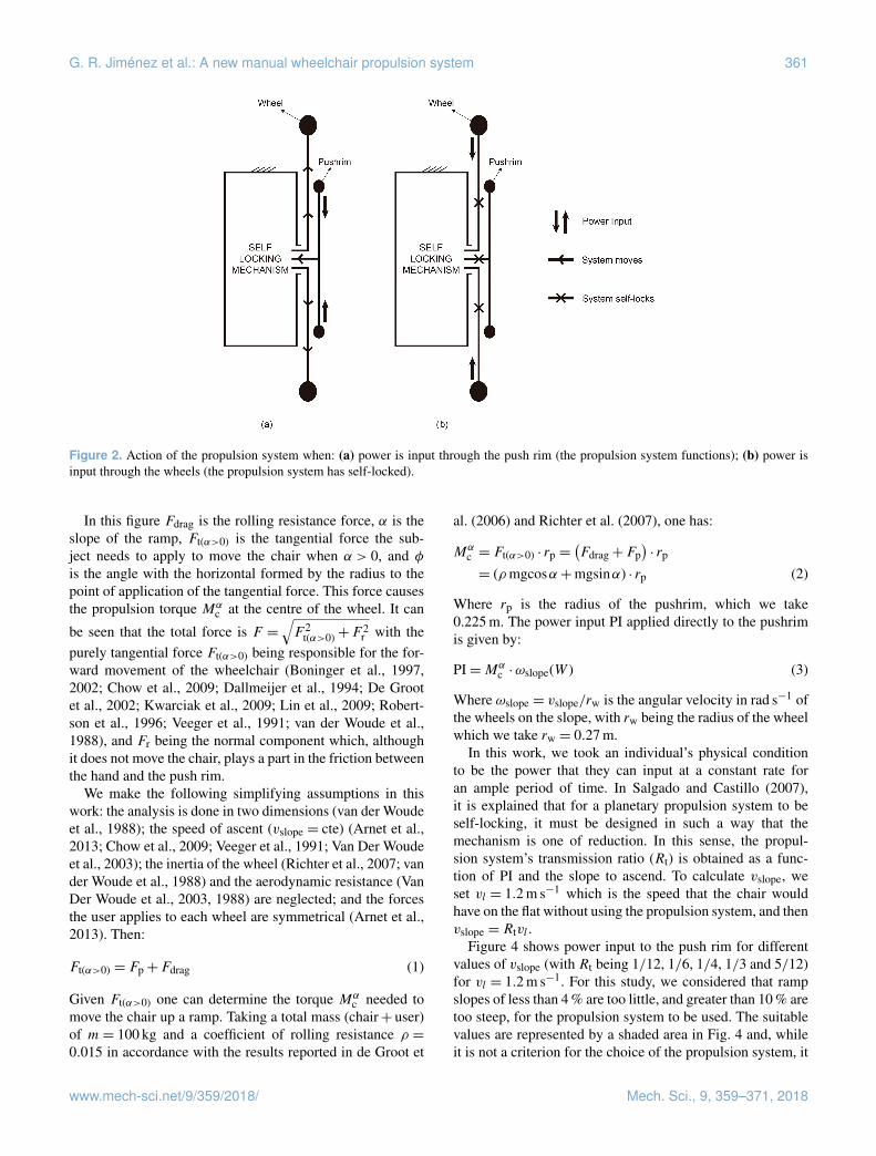
G. R. Jiménez et al.: A new manual wheelchair propulsion system 361
Figure 2. Action of the propulsion system when: (a) power is input through the push rim (the propulsion system functions); (b) power isinput through the wheels (the propulsion system has self-locked).
In this figure Fdrag is the rolling resistance force, α is theslope of the ramp, Ft(α>0) is the tangential force the sub-ject needs to apply to move the chair when α > 0, and φis the angle with the horizontal formed by the radius to thepoint of application of the tangential force. This force causesthe propulsion torque Mα
c at the centre of the wheel. It can
be seen that the total force is F =√F 2
t(α>0)+F2r with the
purely tangential force Ft(α>0) being responsible for the for-ward movement of the wheelchair (Boninger et al., 1997,2002; Chow et al., 2009; Dallmeijer et al., 1994; De Grootet al., 2002; Kwarciak et al., 2009; Lin et al., 2009; Robert-son et al., 1996; Veeger et al., 1991; van der Woude et al.,1988), and Fr being the normal component which, althoughit does not move the chair, plays a part in the friction betweenthe hand and the push rim.
We make the following simplifying assumptions in thiswork: the analysis is done in two dimensions (van der Woudeet al., 1988); the speed of ascent (vslope = cte) (Arnet et al.,2013; Chow et al., 2009; Veeger et al., 1991; Van Der Woudeet al., 2003); the inertia of the wheel (Richter et al., 2007; vander Woude et al., 1988) and the aerodynamic resistance (VanDer Woude et al., 2003, 1988) are neglected; and the forcesthe user applies to each wheel are symmetrical (Arnet et al.,2013). Then:
Ft(α>0) = Fp+Fdrag (1)
Given Ft(α>0) one can determine the torque Mαc needed to
move the chair up a ramp. Taking a total mass (chair+ user)of m= 100 kg and a coefficient of rolling resistance ρ =0.015 in accordance with the results reported in de Groot et
al. (2006) and Richter et al. (2007), one has:
Mαc = Ft(α>0) · rp =
(Fdrag+Fp
)· rp
= (ρmgcosα+mgsinα) · rp (2)
Where rp is the radius of the pushrim, which we take0.225 m. The power input PI applied directly to the pushrimis given by:
PI=Mαc ·ωslope(W ) (3)
Where ωslope = vslope/rw is the angular velocity in rad s−1 ofthe wheels on the slope, with rw being the radius of the wheelwhich we take rw = 0.27 m.
In this work, we took an individual’s physical conditionto be the power that they can input at a constant rate foran ample period of time. In Salgado and Castillo (2007),it is explained that for a planetary propulsion system to beself-locking, it must be designed in such a way that themechanism is one of reduction. In this sense, the propul-sion system’s transmission ratio (Rt) is obtained as a func-tion of PI and the slope to ascend. To calculate vslope, weset vl = 1.2 m s−1 which is the speed that the chair wouldhave on the flat without using the propulsion system, and thenvslope = Rtvl .
Figure 4 shows power input to the push rim for differentvalues of vslope (with Rt being 1/12, 1/6, 1/4, 1/3 and 5/12)for vl = 1.2 m s−1. For this study, we considered that rampslopes of less than 4 % are too little, and greater than 10 % aretoo steep, for the propulsion system to be used. The suitablevalues are represented by a shaded area in Fig. 4 and, whileit is not a criterion for the choice of the propulsion system, it
www.mech-sci.net/9/359/2018/ Mech. Sci., 9, 359–371, 2018

362 G. R. Jiménez et al.: A new manual wheelchair propulsion system
Figure 3. The forces and torques on the push rim of the wheelchair when climbing a slope at constant speed.
does establish an approximation of the minimum and maxi-mum ramps that a user can take on. The figure represents byway of example a user whose physical capacity allows themto input PI= 50 W at the push rim. Depending on the slopeto ascend, one obtains the corresponding values of Rt repre-sented by the points (P1, P2, P3, P4). With the same PI, theuser is able to climb ramps ranging from 4.7% at a speed ofvslope = 0.5 m s−1 to 13.7 % at a speed of vslope = 0.2 m s−1.This graphic thus makes it possible to clearly see the valuesof Rt the user will need to climb certain ramps depending onthe PI they are capable of.
The behaviour of the propulsion system was verified by asimulation in which a user wishes to climb a ramp of approx-imately 5 % slope and is capable of inputting a power PI=50 W for a long period of time. Taking vl = 1.2 m s−1 as inFig. 4, one can see that these data correspond approximatelyto the point P1, with Rt = 5/12, i.e., vslope = 0.5 m s−1. Fig-ure 5 shows the user performing a complete push cycle whileclimbing a ramp. When the user stops inputting power, thesystem locks (Fig. 5b). When, at any time, the user wishes toresume the ascent they can do so by simply applying powerto the push rim, avoiding having to overcome the force ofinertia.
Now that one knows the transmission ratios that are bestadapted to each user depending on their physical conditionand the slope that they want to ascend, in the following sec-tion we shall explain the design of the self-locking propul-sion system.
4 Design of the self-locking propulsion system
For a PGT to be self-locking, it must satisfy a series of designconditions which mean that only a small set of constructionsolutions are possible (Salgado and Castillo, 2007). In thissection, we shall determine a solution for the self-lockingsystem proposed in Fig. 2.
For simplicity of construction, we shall analyse the two4-member self-locking PGT solutions since these are theones with the fewest possible members (Fig. 6). For the de-sign proposed in the present work, we chose the solution ofFig. 6a because it has gear pairs that are external (gear/gear)rather than internal (gear/ring gear). For this construction so-lution to be self-locking, the following expression must besatisfied (Salgado and Castillo, 2007):
η14η24 <Z24
Z14<
1η14η24
(4)
where ηij is the ordinary efficiencies of the circuits of thePGT. The ordinary efficiency is the efficiency of the gear pairif the arm linked to the planet were fixed. By means of this ef-ficiency, one introduces into the overall efficiency calculationof the gear train the friction losses that take place in each gearpair. Although the value of the ordinary efficiency in eachgear pair depends on the number of teeth of its gears, on theoperating conditions (applied torque, speed, lubricant typeand method, temperature), and on geometric factors such asthe approach portion and the recess portion and on tooth sur-face roughness (Anderson and Loewenthal, 1980; Diab et al.,2006; Müller, 1982; Xu and Kahraman, 2005), for the anal-ysis of the self-locking conditions; it is sufficient to considera value of the ordinary efficiencies slightly less than unity
Mech. Sci., 9, 359–371, 2018 www.mech-sci.net/9/359/2018/

G. R. Jiménez et al.: A new manual wheelchair propulsion system 363
Figure 4. Diagram of the transmission ratios Rt and speed of climb for a given vl = 12 m s−1 as functions of the slope to ascend and thepower PI that the user inputs to the chair.
(Salgado and Castillo, 2007). In Eq. (4) Zij is the tooth ratioof the gear pair formed by the linking members i andj . Inparticular, Zij is defined as Zij = Zi/Zj . For the definitionof the tooth ratios to satisfy the Willis equations, Zij must bepositive if the gear is external (meshing gear–gear) and neg-ative if it is internal (meshing ring gear–gear). For the trainof Fig. 6a, one would have to take Z14 > 0 and Z24 > 0.
The two construction solutions for a 4-member self-locking PGT only allow power flow with input through thearm (Member 3) and output through the sun (Member 1),as shown in Fig. 6, where the power flow is in the direc-tion marked by the arrow. The transmission ratio of the four-member PGT with input through the arm is (Salgado andCastillo, 2007):
r =Z14−Z24
Z14(5)
For the design of the wheelchair locking system based onPGTs, we have considered the constraints on this type oftransmission. These constraints can be grouped into two cat-egories – one involving gear size and geometry, and the otherthe PGT meshing requirements, as will be detailed in the fol-lowing two subsections.
4.1 Constraints involving gear size and geometry
The first constraint is a practical limitation of the range forthe acceptable face width b. This constraint is as follows:
9m< b < 14m (6)
Wherem is the module of the gears. All of the kinematic anddynamic parameters of the transmission depend on the valuesof the tooth ratios Zij . In theory, the tooth ratios can take anyvalue, but in practice, they are limited mainly for technicalreasons because of the difficulty in assembling gears outsideof a certain range of tooth ratios. In this work, the tooth ratiofor the design of mechanical spindle speeders are quite closeto the recommendations of Müller (1982) and the AmericanGear Manufacturers Association (AGMA) norm (AmericanGear Manufacturers Association, 1988), and are:
0.2< Zij < 5 (7)− 7< Zij <−2.2 (8)
with the constraint given by Eq. (7) being for external gearsand that by Eq. (8) for internal gears. It is important to notethat these constraints are valid for designs with differentnumbers of planets (Np) (Müller, 1982).
Another constraint that will be imposed on the design of4-PGT with double planets, as the self-locking PGT imple-mented in the locking system design, is that the ratio of thediameters of the gears constituting a double planet is:
13<d4
d4′< 3 (9)
where d4 and d4′ are the pitch diameters of the gears thanconstitutes the planet gear that meshes with members 1 and2 (see Fig. 6).
www.mech-sci.net/9/359/2018/ Mech. Sci., 9, 359–371, 2018

364 G. R. Jiménez et al.: A new manual wheelchair propulsion system
Figure 5. Simulation of the ascent of an approximately 5 % slope with velocity vl = 1.2 m s−1 and Rt = 5/12. (a) The stages of a push cyclein which step A is the start, B is halfway through the push, C is the end of the push cycle, and D is when the user stops inputting power whilestill situated on the ramp; (b) the corresponding speeds vl and vslope.
Figure 6. Construction solutions for four-member planetary geartrains. (a) External gears. (b) Internal gears.
4.2 Planetary gear train meshing requirements
The meshing requirements are given by the AGMA norm(American Gear Manufacturers Association, 1988). For plan-etary systems with double planets must, either of which, fac-torise with the number of planets in the sense of Eq. (10)below (see AGMA norm; American Gear Manufacturers As-sociation, 1988):
Z2P2±Z1P1
Np= an integer (10)
where P1 and P2 are the numerator and denominator of theirreducible fraction equivalent to the fraction Z4′/Z4; whereZ4′ is the number of teeth of the planet gear that meshes withmember 1 and Z4 is the number of teeth of the planet gearthat meshes with member 2 (see Fig. 6):
Z4′
Z4=P1
P2(11)
It can be verified that to satisfy the above requirements, andgiven that the 4-member PGT with arm input is a reductiontransmission, the maximum transmission ratio (minimum re-duction) that can be achieved so that a self-locking train isobtained, i.e., so that the constraints of Eqs. (4)–(11) are sat-isfied, is the one that hasRt = 1/12. Of the possible transmis-sion ratios for a self-locking PGT, we chose this maximum.
As a specific design proposal to achieve Rt = 1/12, wepropose the following teeth numbers for the self-lockingPGT: Z1 = 48, Z2 = 44, Z4 = 20 and Z4′ = 20.
As mentioned above, and as can be checked in Fig. 4, thelogical Rt values go from 5/12 to 1/12. Therefore, only inone case is the propulsion system a self-locking PGT. Forthe rest of the PI and slope values, a self-locking PGT +multiplier combination is necessary. In this work, we proposea PGT as multiplier stage since the speed is multiplied in asingle step.
The self-locking PGT design with the planet member con-sisting of four gears (Np = 4) is shown in Fig. 7a, and Fig. 7bis a schematic diagram of the complete propulsion system(self-locking PGT+multiplier PGT). The self-locking PGTis common to any design of the propulsion system. The mem-
Mech. Sci., 9, 359–371, 2018 www.mech-sci.net/9/359/2018/

G. R. Jiménez et al.: A new manual wheelchair propulsion system 365
Figure 7. (a) Design of the self-locking Planetary Gear Train with Rt = 1/12. (b) Scheme of the complete propulsion system.
ber that varies depending on the needs of the user is the mul-tiplier stage.
4.3 Force and stress analysis
As an example, we use an intermediate transmission ratioRt = 5/12, which is the result of combining a self-lockingPGT with Rt = 5/12 and a multiplier PGT with Rt = 5. Theobjective is to evaluate whether the propulsion system issmall in size. To perform the calculations, two phases mustbe distinguished: when the system is locked, and when PI isinput through the pushrim.
In the locking phase of the propulsion system, the value ofRt of the system is irrelevant since the stresses produced inthe system depend solely on the slope and the chair-plus-usermass. For the calculations in this phase, one must decide onthe value of the slope. We shall take a slope of 10 %. Sincethe system is locked, Fdrag = 0 because it is not necessaryto overcome any forces of friction. Thus, considering m=100 kg, the only force that the system supports is that of theweight, Fp:
Ft(α>0) = Fp+Fdrag =mgsinα+ 0= 97.6N (12)
The radius of the Wheel, rw is 270 mm. If no reduction sys-tem is used, the torque produced on the wheel’s axis duringthis locking phase on a slope of 10 % will be:
Mαc = Fprw = 26.35Nm (13)
This torque is distributed symmetrically through the twodrive wheels. Hence, each locking system receives a torque
of Mαc = 13.17 Nm. Each drive wheel is connected to the
self-locking PGT’s output gear (Gear 1) which will receivethe full torque, and trigger the locking. Using the valuesgiven in Table 1 for the dimensions of the elements con-forming the propulsion system, the tangential force producedby Mα
c = 26.35 Nm on the cogs of Gear 1 will be Ft(α>0) =
233.2 N. Since they belong to the same member, planets 4′
and 4 distribute the torque produced by the locking symmet-rically, and this will be that given by the tangential force ex-erted by the cogs of Gear 1. Figure 8 shows a method for cal-culating the resistance of the mechanism. This is the methodused in Hwang et al. (2013), Li (2012), Moreira et al. (2016)and Patil et al. (2014) in which the resistance of the cog iscalculated from the tangential force Ft(α>0) caused by thetorque produced at the centre of the gear’s pitch radius.
When power is input through the push rim, the equa-tions proposed in Del Castillo (2002) are used to calculatethe torques and angular velocities of the components of thepropulsion system (self-locking PGT+multiplier PGT) withpower input to the self-locking PGT through the arm. Thesecalculations were done using software developed in Matlabbased on the aforementioned equations. Table 1 gives the sizeand dynamic characteristics of each member of the mecha-nism when a torque Mα
c is input through the push rim. Forthe dynamics calculations, we considered the values of Rtrepresented in Fig. 4.
The increase in the torques produced in the self-lockingPGT elements is due to the power recirculation that occursin this type of self-locking PGT (Del Castillo, 2002). Thus,
www.mech-sci.net/9/359/2018/ Mech. Sci., 9, 359–371, 2018

366 G. R. Jiménez et al.: A new manual wheelchair propulsion system
Figure 8. (a) Stresses produced by the tangential forces applied to the cog during the blocking phase. (b) Areas in which the differentcontacts occur, and the application of the tangential force Fαt produced by the contact in the least favourable area.
Table 1. Size characteristics of the gears conforming the propulsion system, and the contact ratios between elements in contact and thedynamic loads on each element when Mα
c is input through the pushrim.
System Member Teeth Pitch Diameter Thickness Module Contact Ratio Torque Angular speed(mm) (mm) (mm) (xNp) (Nm) (rpm)
Arm – – Mαc ωl
Self-locking PGT (Rt = 1/12) 1 48 113 5 2.35 1.61 (×4) 5.79Mαc 1/12ωl
4′ 20 47 2.29Mαc 3.2ωl
2 44 110 2.5 1.64 (×4) 4.79Mαc 0
4 20 50 2.29Mαc 3.2ωl
Multiplier (Rt = 5) Ring 120 180 5 1.5 > 3 (×3) 4.67Mαc 0
Planet 45 67.5 1.695 (×3) 1.72Mαc 1.66/12ωl
Sun 30 45 1.12Mαc 5/12ωl
Multiplier (Rt = 4) Ring 90 180 5 2 > 3 (×3) 4.39Mαc 0
Planet 30 60 1.654 (×3) 1.43Mαc 1/6ωl
Sun 30 60 1.40Mαc 1/3ωl
Multiplier (Rt = 3) Ring 80 160 5 2 > 3 (×4) 3.91Mαc 0
Planet 20 40 1.635 (×4) 0.96Mαc 1/4ωl
Sun 40 80 1.88Mαc 1/4ωl
Arm – – – 2.77Mαc 1/6ωl
Multiplier (Rt = 2) 2 60 99.6 5 1.66 1.719 (×3) 5.79Mαc 1/12ωl
4′ 30 49.8 2.95Mαc 1/3ωl
1 30 75 2.5 1.654 (×3) 2.77Mαc 0
4 30 75 2.95Mαc 1/3ωl
unlike in the locking phase of the system when the maximumtorque supported by the self-locking PGT is limited by thesize of the gears and the weight of the user, in this phase thelimiting variable is the torque that is input onto the push rimwhere the greatest stresses arise.
As an example, we present a calculation of the stressesthat arise on the cogs of the PGT’s gears when a user isable to input a power of approximately 70 W, and wishes toclimb a 7 % ramp. According to Fig. 4, the transmission ra-tio that is best suited to the needs of this case is Rt = 5/12.
The speed of ascent, vslope = 0.5 m s−1 is the consequence ofinputting approximately Mα
c = 19 Nm at ωl = 4.44 rad s−1,which means that 9.5 Nm is applied to each push rim. As oneobserves in Table 1, taking into account the dimensions ofthe components of both the self-locking and the multiplierstages, the component which supports the greatest stress isPlanet 4′ of the self-locking PGT. The results of the dynamicsimulation with this force applied to the cog as in Fig. 8 areshown in Fig. 9.
Mech. Sci., 9, 359–371, 2018 www.mech-sci.net/9/359/2018/

G. R. Jiménez et al.: A new manual wheelchair propulsion system 367
Figure 9. Stresses produced by the tangential forces applied to the cog when the user inputs power through the push rim: the dynamic loadson Member 4′ (the least favourable).
Table 2. Characteristics of the elements conforming the proposed propulsion system with Rt = 5/12.
Member Material (Density) Mass Total Member mass (g) Thickness (mm) Diameter (mm)
Arm Rigid PVC 111.86 628.14 10 –Z2 Alloyed cast steel 311.54 311.54 5 110Z4 Alloyed cast steel 63.16 252.64 5 50Z4′ Alloyed cast steel 55.11 220.44 5 47Z1 Alloyed cast steel 355.33 355.33 5 113Ring Alloyed cast steel 474.91 474.91 5 200Sun Alloyed cast steel 277.76 277.76 5 100Planet Alloyed cast steel 65.87 197.61 5 50Planets carrier Rigid PVC 173.4 173.4 5 –
Total 2891.77 30 202.5 (dedendum diameter)
The cogs of Member 4′ can withstand the effects producedeven in situations of steep slopes. This method has thereforeallowed us to define the thicknesses and diameters of all thegears, and hence we can also define the approximate dimen-sions of the complete propulsion system.
With the stresses that arise in the elements of the propul-sion system known, and its viability in terms of resistanceconfirmed, we can now approximate the overall dimensionsof the system, as is illustrated in Fig. 10a for Rt = 5/12. Anexploded view of the mechanism is included in Fig. 10b.
Table 2 lists the specifications of each element of the trans-mission for Rt = 5/12. A relationship is established betweenthe width and the height of the casing enclosing the trans-mission in order to have an approximation of the system’sviability in terms of its dimensions.
5 Functional and qualitative evaluation
In this work a prototype of the propulsion system has beentested in order to validate the reliability and the behaviourof the self-locking system in manual wheelchairs. The gearsthat formed the self-locking PGT and the multiplier stagewere made of alloy steel. A ball bearing was used in gear 1with 12 mm of diameter, the rest of the bearings of the pro-totype were needle bearings with 10 mm diameter each. Themounting of the prototype was as follows: gear 2 and the firstpart of the housing were joined together with screws whichprevented gear 2 from moving. Planet gears 4 and 4′, theplanet carrier and the input arm were mounted together. Inthis prototype a speed multiplier with a speed ratio of 5 : 1was mounted at the output of gear 1. The sun element ofthe speed multiplier (output of the transmission) was con-nected to the wheel of the wheelchair. The second part of
www.mech-sci.net/9/359/2018/ Mech. Sci., 9, 359–371, 2018

368 G. R. Jiménez et al.: A new manual wheelchair propulsion system
Figure 10. (a) Diagram of the final transmission with the approximate values in mm of the width and height of the casing enclosing it,(b) Exploded view of the propulsion mechanism using a stage multiplier ×5.
Figure 11. (a) Side view of the manual wheelchair with the propulsion system. (b) Rear view.
the housing encapsulated the transmission, thus forming anassembly which was subsequently joined to the chassis ofthe wheelchair using screws, leaving the housing as the fixedelement of the transmission. An external pushrim was in-stalled and connected to the input arm with the purpose ofintroducing power to the propulsion system. As mentionedin Fig. 1 there were two possible arrangements for the trans-mission, and the decision was taken to mount the prototypeunderneath the seat as can be seen in Fig. 11b which showsa rear view of the wheelchair. This configuration does not
increase the width of the whole system. Once the prototypewas mounted, the transmission had a Rt = 5/12.
The trials were conducted on a healthy subject with aheight of 1.80 m and a mass of 80 kg. The ramp used for thetrials was located at the main entry of a residential area, it hada 10 % slope and a length of 15 m. The first trial consistedof analysing the self-locking characteristic of the prototype.The subject was told to remain stationary and not to movethe external pushrim. While the subject was on the slope inan uphill direction the power input was transferred from the
Mech. Sci., 9, 359–371, 2018 www.mech-sci.net/9/359/2018/

G. R. Jiménez et al.: A new manual wheelchair propulsion system 369
Figure 12. (a, b) Different views of the propulsion system withoutpower input (system self-locks) during both ascending (a) and de-scending trials (b). (c, d) Different views of the propulsion systemwith power input through the external rim (system moves) duringboth ascending (c) and descending trials (d).
wheel to the output of the self-locking PGT (gear 1), provok-ing the locking of the system and preventing the subject fromrolling backwards. In the same way, when the subject wasin a downhill direction, the prototype also self-locked. Thesubject was comfortable and did not feel any risk of rollingbackwards or forwards while the prototype was locked. Ascan be seen in Fig. 12, panel (a) shows the user on an uphillramp and panel (b) shows the user on a downhill ramp whenthe prototype is in the locking position. The first trial demon-strated that the system self-locked while the user was on aramp without any power input.
The second trial consisted of introducing power throughthe external pushrim in order to test the motion of theprototype. By moving the external pushrim of the proto-type, the power input was transferred from the input armand thus moving gears 4 and 4′, provoking the motion ofgear 1 (output of self-locking PGT) and consequently mov-
ing the wheelchair. The subject was told to move the pushrimat the speed he considered appropriate. While pushing thewheelchair through various cycles and then halting the mo-tion, the subject felt comfortable throughout the trial and didnot feel at risk of rolling backwards or forwards. Further, theuser did not feel the effects of inertia when changing betweena stationary position and motion. In Fig. 12 the user is intro-ducing power to the system through the new external rim inboth ascending (panel c) and descending (panel d) ramps.The ramp used was 10 % slope. Different repetitions ascend-ing and descending the ramp were carried out.
It is evident that, on one hand, the system self-locks whenthe power is introduced through the wheel in both ascend-ing and descending trials (Fig. 12, panels a and b). This be-haviour prevents the user from going backwards ascendingor going downhill while descending. On the other hand thesystem moves while the power is introduced through the ex-ternal rim (Fig. 12, panels c and d).
6 Conclusions
In this work, we have described the design of a new propul-sion system applied to manual wheelchairs for the ascent ordescent of long ramps. The system consists of a self-lockingplanetary transmission and a push rim through which poweris input to the mechanism. With this configuration, it is pos-sible to design a system that makes it easier for the user toascend long ramps and that self-locks when the user stopsinputting power through the push rim. The chair thereforestops without any need for an external braking mechanism tobe activated. Although the system is designed especially forclimbing long ramps since this is the least favorable situa-tion, it also allows the descent of ramps. In addition, it can beadapted to each user’s physical conditions by selecting eachtransmission ratio according to that user’s needs dependingon the power that they can transmit.
It has to be emphasized that the system is made up of me-chanical components and requires no external elements forits activation or deactivation. This allows the user to push thechair without fearing when it might be descending. Addition-ally, when they wish to resume motion, they will not need toovercome the force of inertia, but rather simply start pushingthe chair again. All this makes the design characteristics ofthe propulsion system proposed in this work adaptable to anyuser.
Finally, the transmission was also built and tested on amanual wheelchair. In a qualitative way it has been demon-strated that the system self-locks while both ascending anddescending a ramp when the power is introduced throughthe wheels. It has also been demonstrated that the propulsionsystem moves the wheelchair when the power is introducedthrough the external rim. For future works, lighter materi-als and considerations regarding the size of the device willbe taken into account. The device will also be tested on im-
www.mech-sci.net/9/359/2018/ Mech. Sci., 9, 359–371, 2018
370 G. R. Jiménez et al.: A new manual wheelchair propulsion system
paired users with lower limb injuries and further studies likeenergy consumption and muscle behaviour will be analysed.
Data availability. All the data used in this article can be obtainedupon request from the corresponding author.
Competing interests. The authors declare that they have noconflict of interest.
Edited by: Chin-Hsing KuoReviewed by: two anonymous referees
References
American Gear Manufacturers Association: American Nationalstandard?: design manual for enclosed epicyclic metric modulegear drivers, American Gear Manufacturers Association, USA,1988.
Anderson, N. E. and Loewenthal, S. H.: Spur-gear-system efficiencyat part and full load, NASA Tech. Rep., 79–46, 1980.
Arnet, U., Van Drongelen, S., Veeger, D. J., and Van Der Woude,L. H. V.: Force application during handcycling and handrimwheelchair propulsion: An initial comparison, J. Appl. Biomech.,29, 687–695, https://doi.org/10.1123/jab.29.6.687, 2013.
Boninger, M. L., Cooper, R. A., Robertson, R. N., and Shimada,S. D.: Three-dimensional pushrim forces during two speeds ofwheelchair propulsion, Am. J. Phys. Med. Rehab., 76, 420–426,1997.
Boninger, M. L., Souza, A. L., Cooper, R. A., Fitzgerald,S. G., Koontz, A. M., and Fay, B. T.: Propulsion pat-terns and pushrim biomechanics in manual wheelchairpropulsion, Arch. Phys. Med. Rehab., 83, 718–723,https://doi.org/10.1053/apmr.2002.32455, 2002.
Choi, Y. O., Lee, H. Y., Lee, M. H., and Kwon, O. H.: Effects oframp slope on physiological characteristic and performance timeof healthy adults propelling and pushing wheelchairs, J. Phys.Ther. Sci., 27, 7–9, https://doi.org/10.1589/jpts.27.7, 2015.
Chow, J. W., Millikan, T. A., Carlton, L. G., Chae, W. S., Lim, Y. T.,and Morse, M. I.: Kinematic and Electromyographic Analysis ofWheelchair Propulsion on Ramps of Different Slopes for YoungMen With Paraplegia, Arch. Phys. Med. Rehab., 90, 271–278,https://doi.org/10.1016/j.apmr.2008.07.019, 2009.
Dallmeijer, A. J., Kappe, Y. J., Veeger, D. H. E. J., Janssen, T.W. J., and van der Woude, L. H. V.: Anaerobic power outputand propulsion technique in spinal cord injured subjects duringwheelchair ergometry, J. Rehabil. Res. Dev., 31, 120–128, 1994.
De Groot, S., Veeger, H. E. J., Hollander, A. P., and Van der Woude,L. H. V.: Consequence of feedback-based learning of an effectivehand rim wheelchair force production on mechanical efficiency,Clin. Biomech., 17, 219–226, https://doi.org/10.1016/S0268-0033(02)00005-0, 2002.
de Groot, S., Zuidgeest, M., and van der Woude, L. H. V.: Standard-ization of measuring power output during wheelchair propulsionon a treadmill. Pitfalls in a multi-center study, Med. Eng. Phys.,28, 604–612, https://doi.org/10.1016/j.medengphy.2005.09.004,2006.
Del Castillo, J. M.: The analytical expression of the efficiencyof planetary gear trains, Mech. Mach. Theory, 37, 197–214,https://doi.org/10.1016/S0094-114X(01)00077-5, 2002.
Diab, Y., Ville, F., and Velex, P.: Prediction of Power LossesDue to Tooth Friction in Gears, Tribol. T., 49, 266–276,https://doi.org/10.1080/05698190600614874, 2006.
Flemmer, C. L. and Flemmer, R. C.: A review of manualwheelchairs Claire, Disabil. Rehabil. Assist. Technol., 11, 177–187, https://doi.org/10.3109/17483107.2015.1099747, 2016.
Howarth, S. J., Pronovost, L. M., Polgar, J. M., Dickerson, C. R.,and Callaghan, J. P.: Use of a geared wheelchair wheel to re-duce propulsive muscular demand during ramp ascent: Analysisof muscle activation and kinematics, Clin. Biomech., 25, 21–28,https://doi.org/10.1016/j.clinbiomech.2009.10.004, 2010.
Hwang, S. C., Lee, J. H., Lee, D. H., Han, S. H., and Lee, K. H.:Contact stress analysis for a pair of mating gears, Math. Comput.Model., 57, 40–49, https://doi.org/10.1016/j.mcm.2011.06.055,2013.
Koontz, A. M., Cooper, R. A., Boninger, M. L., Yang, Y., Im-pink, B. G., and van der Woude, L. H. V.: A kinetic analy-sis of manual wheelchair propulsion during start-up on selectindoor and outdoor surfaces, J. Rehabil. Res. Dev., 42, 447,https://doi.org/10.1682/JRRD.2004.08.0106, 2005.
Kwarciak, A. M., Yarossi, M., Ramanujam, A., Dyson-Hudson, T. A., and Sisto, S. A.: Evaluation of wheelchairtire rolling resistance using dynamometer-based coast-down tests, J. Rehabil. Res. Dev., 46, 931–938,https://doi.org/10.1682/JRRD.2008.10.0137, 2009.
Li, S.: Contact Stress and Root Stress Analyses of Thin-RimmedSpur Gears With Inclined Webs, J. Mech. Design, 134, 51001,https://doi.org/10.1115/1.4006324, 2012.
Lin, C.-J., Lin, P.-C., Su, F.-C., and An, K.-N.: Biomechanicsof wheelchair propulsion, J. Mech. Med. Biol., 9, 229–242,https://doi.org/10.1142/S0219519409002948, 2009.
Meginniss, S. M. and SanFrancisco, A. S.: Two-Speed man-ual wheelchair wheel, United States Pat. Appl. Publ., 53, US2006/0197302 A1, 2006.
Moreira, P., Ramôa, P., and Flores, P.: Design of a new kneeorthosis locking system, Proceedings of the ASME 2013 In-ternational Mechanical Engineering Congress and ExpositionIMECE2013, 15–21 November 2013, San Diego, California,USA, https://doi.org/10.1115/IMECE2013-64276, 2016.
Müller, H.: Epicyclic drive trains: Analysis, synthesis, and applica-tions, Wayne University Press, Detroit, USA, 1982.
Patil, S., Karuppanan, S., Atanasovska, I., and Wahab, A. A.: Fric-tional Tooth Contact Analysis along Line of Action of a SpurGear Using Finite Element Method, Proc. Mat. Sci., 5, 1801–1809, https://doi.org/10.1016/j.mspro.2014.07.399, 2014.
Richter, W. M., Rodriguez, R., Woods, K. R., and Ax-elson, P. W.: Stroke Pattern and Handrim Biomechan-ics for Level and Uphill Wheelchair Propulsion at Self-Selected Speeds, Arch. Phys. Med. Rehab., 88, 81–87,https://doi.org/10.1016/j.apmr.2006.09.017, 2007.
Robertson, R. N., Boninger, M. L., Cooper, R. A., and Shi-mada, S. D.: Pushrim forces and joint kinetics duringwheelchair propulsion, Arch. Phys. Med. Rehab., 77, 856–864,https://doi.org/10.1016/S0003-9993(96)90270-1, 1996.
Mech. Sci., 9, 359–371, 2018 www.mech-sci.net/9/359/2018/

G. R. Jiménez et al.: A new manual wheelchair propulsion system 371
Salgado, D. R. and Castillo, J. M.: Conditions for self-locking inplanetary gear trains, J. Mech. Des.-T. ASME, 129, 960–968,https://doi.org/10.1115/1.2748449, 2007.
Sonenblum, S. E., Sprigle, S., and Lopez, R. A.: Manual WheelchairUse: Bouts of Mobility in Everyday Life, Rehabil. Res. Pract.,2012, 1–7, https://doi.org/10.1155/2012/753165, 2012.
Sprigle, S. and Huang, M.: Impact of Mass and Weight Distribu-tion on Manual Wheelchair Propulsion Torque, Assist. Technol.,27, 226–235, https://doi.org/10.1080/10400435.2015.1039149,2015.
van der Woude, L., Dallmeijer, A., Janssen, T., and Dirjkan, V.:Alternative Modes of Manual Wheelchair Ambulation, Am. J.Phys. Med. Rehab., 80, 765–777, doi:10.0894-9115/01/8010-0765/0, 2001.
van der Woude, L. H., Hendrich, K. M., Veeger, H. E. J., van In-gen Schenau, G. J., Rozendal, R. H., de Groot, G., and Hollan-der, A. P.: Manual wheelchair propulsion: effects of power outputon physiology and technique, Med. Sci. Sport. Exer., 20, 70–78,https://doi.org/10.1249/00005768-198802000-00011, 1988.
Van Der Woude, L. H. V., Geurts, C., Winkelman, H., and Veeger,H. E. J.: Measurement of wheelchair rolling resistance with ahandle bar push technique, J. Med. Eng. Technol., 27, 249–258,https://doi.org/10.1080/0309190031000096630, 2003.
van der Woude, L. H. V., de Groot, S., and Janssen, T. W. J.:Manual wheelchairs: Research and innovation in rehabilitation,sports, daily life and health, Med. Eng. Phys., 28, 905–915,https://doi.org/10.1016/j.medengphy.2005.12.001, 2006.
Vanlandewijck, Y., Theisen, D., and Daly, D.: Wheelchairpropulsion biomechanics: implications for wheelchair sports,Sport. Med., 31, 339–367, https://doi.org/10.2165/00007256-200131050-00005, 2001.
Veeger, H. E. J., Van Der Woude, L. H. V., and Rozen-dal, R. H.: Load on the Upper Extremity in ManualWheelchair Propulsion, J. Electromyogr. Kines., I, 270–280,https://doi.org/10.1016/1050-6411(91)90014-V, 1991.
Xu, H. and Kahraman, A.: A Frictional Efficiency Loss Model forHelical Gears, ASME 2005 Int. Des. Eng. Tech. Conf. Com-put. Inf. Eng. Conf., 1–12, https://doi.org/10.1115/DETC2005-85243, 2005.
www.mech-sci.net/9/359/2018/ Mech. Sci., 9, 359–371, 2018