completer motor protection
TRANSCRIPT

OM SAI INSTITUTE OF TECHNOLOGY & SCIENCE
Session: 2014 - 2015
Seminar Presentation On COMPLETER PROTECTION OF MOTOR
Guided by: Represented by-: Mr. NEERAJ KR SHARMA KULDEEP PAL
(E.E.E Dept.) E.N(4TH )YEAR 1149721009
1

Have you ever lost a motor?
• Caused a loss of production• Same motor over and over again?• While you were away from the plant?• Something happened on the power company
side.• Didn’t know why?
Why Do Motors Fail?
Common Causes of Motor Failures

Causes of Motor Breakdown
• Thermal•Over voltage•Over current

Rules of Breakdown
• Rule of thumb:
A 10o C temperature rise above rated temperature will half the life of a motor
The flow of over voltage more than rated voltage can damage immediately
The flow of over current more than rated current can damage motor
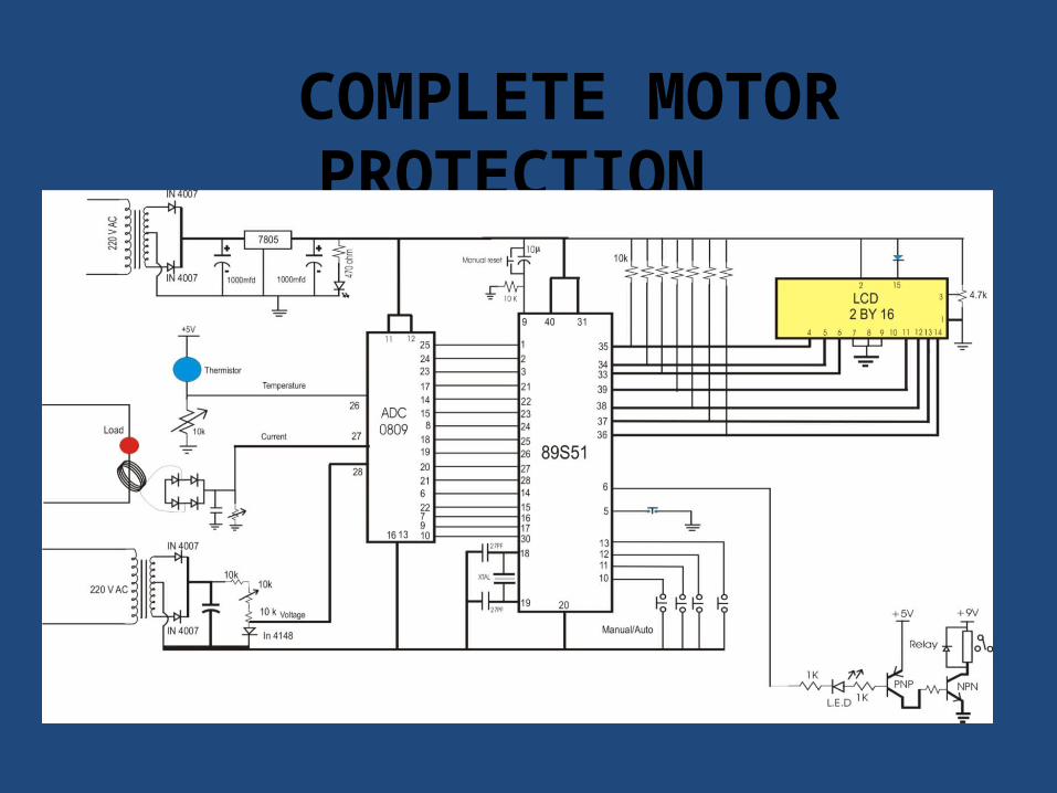
COMPLETE MOTOR PROTECTION

INTRODUCTION• In this project we show that how we provide completer protection for any motor
or load with over temperature, over current, over voltage.• In this project we not only measure the current value but at the same time
control the upper limit of these parameters automatically.• In this project we use one relay for load on/off with manual switch. When we
switch on the circuit then circuit lcd display the current value of temperature, voltage and current.
• we press the start switch to on/off the relay coil. As the relay is on circuit immediate on the relay.
• Now we measure the different parameters of the load with temperature, current and voltage.
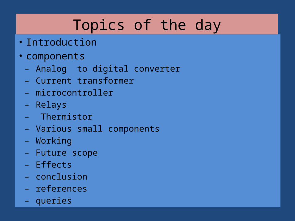
Topics of the day• Introduction• components– Analog to digital converter– Current transformer– microcontroller– Relays – Thermistor – Various small components– Working– Future scope– Effects– conclusion– references– queries
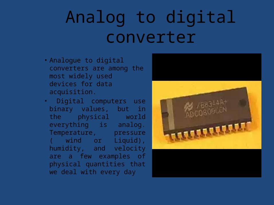
Analog to digital converter
• Analogue to digital converters are among the most widely used devices for data acquisition.
• Digital computers use binary values, but in the physical world everything is analog. Temperature, pressure ( wind or Liquid), humidity, and velocity are a few examples of physical quantities that we deal with every day
CURRENT TRANSFORMER
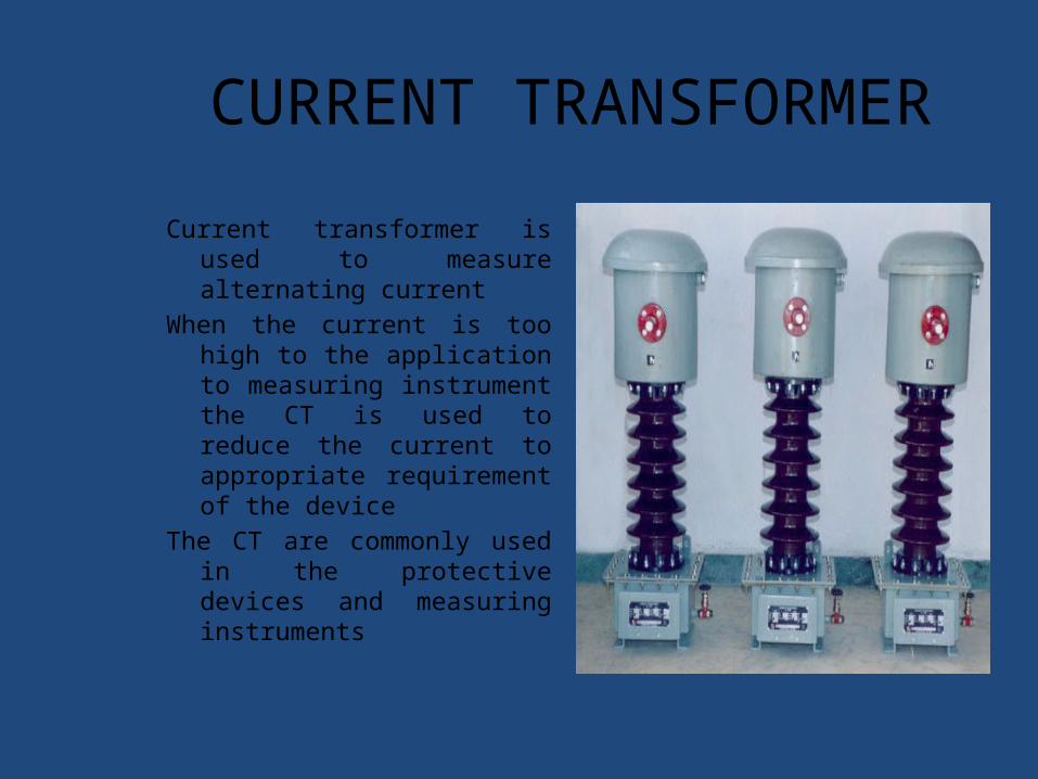
Current transformer is used to measure alternating current
When the current is too high to the application to measuring instrument the CT is used to reduce the current to appropriate requirement of the device
The CT are commonly used in the protective devices and measuring instruments

MICROCONTROLLER
• the microprocessor is more a general-purpose device, used for read, write and calculations on data, the micro controller, in addition to the above functions also
controls the environment.

What are Relays?
• Relays are electrical switches that open or close another circuit under certain conditions.
• Relays are the protective devices• Works as switching device • Relays works very fast as the
switching device

THERMISTORS
THERMISTOR is the type of resistor whose resistance varies with change in temperature more so than in standard resistors.
They are widely used in temperature sensors
The material used in THERMISTOR is a ceramic polymer etc.
They are different from RTDs.

The Ancillary components
DIODESTRANSISTORSSTEP DOWN TRANSFORMER SWITCHESLEDLCDCAPACITORSRESISTORSWIRESIC 7805

WORKING For current measurement we use 2500 turns ct coil. Output of the ct coil is ac voltage and this voltage is converted
into dc voltage with the help of rectifier circuit. Output of the rectifier is further connected to the ADC circuit for digital conversion.
Here we use 0809 ADC for analogue to digital conversion. In this project we use ADC 0809 for 8 channel input signal.
Here we use only three channel for Analogue to digital conversion. These three channel is control by the three address lines, Pin no 23,24,25.
These pins are connected to the microcontroller pin no 1,2,3. By controlling the address lines we get different inputs one by one.
Second input for ADC is Thermistors . Here we use NTC Thermistors with potential divider circuit . Thermistor changes its resistance according to the temperature as the temperature is change resistance of the
thermistor is also change , change of resistance is converted into change of voltage . this change of voltage is connected to the pin no 26 of the ADC.
Pin no 28 is for voltage measurement. We use step down transformer with full wave rectifier+ capacitor circuit for small dc voltage. This small dc voltage is connected to the pin no 28 of the ADC via potential divider circuit..
• Output of the ADC is hex data and this data is further connected to the microcontroller circuit . Microcontroller provides all the control signal to ADC like E.O.C( end of conversion), OE ( output enable), CLOCK, ALE, START.
• Output from the ADC is hex data and this data is further converted into ASCII code with the help of programming. This ASCII code is connected to the LCD directly via pin no 39,36 of controller.
• Here we use 2 by 16 LCD for display current value and set value.• We use four switches to increment and decrement the set values of different parameters.
High Voltage… Effect• Reduced efficiency• Reduced power factor• Increased power consumption• Increased current• Increased temperature

Why Motors Fail...
* Based on 9,000 failure events researched by the Electric Motor Manual which was written by Robert Lawrie in conjunction with the staff at Electric Construction and
Maintenance Magazine.
Rotor Failures5%Failures
Bearing
13%
Contaminants19%
Overload30%
Misc9%
Single Phasing14%Old Age
10%

Overloads
“ It is practically impossible to burn out a motor from overload when it is protected by properly sized and maintained motor protection devices”.
William P. Maples, P.E.
Costs Associated with Motor Failures
• Equipment downtime $$$$• Loss of production• Collateral equipment damage • Equipment replacement• Work in process damage• Overtime for repair crews

In conclusion:• Motors will last a long time if operated within
their design parameters. ( Voltage, current & temperature)
• Identify the cause of your motor failure• When replacing motors also consider changing
overloads and motor start contacts• For critical motors incorporate the latest
motor monitoring products.
CONCLUSION
Reference:
• IEEE Red Book• Ontario Power Generation Training Course
(Electrical Equipment)• www.howstuffworks.com

Thank you!
anyQUERIES ??