computational aspect analysis of real-time systems
TRANSCRIPT

IEEJ Journal of Industry ApplicationsVol.8 No.1 pp.124–130 DOI: 10.1541/ieejjia.8.124
Paper
Computational Aspect Analysis of Real-Time Systems: Application toHDD Servo Control
Kenta Morishima∗a)Non-member, Shigeru Oho∗∗ Member
(Manuscript received May 14, 2018, revised June 27, 2018)
Co-simulation for a hard disk drive (HDD) servo system and its microcontroller control system was developed toanalyze computational aspects of the control system such as memory use and calculation load on processors. Themicrocontroller was modeled with its instruction set simulator that executed the binary codes of control commands.The model also incorporated the peripheral functions of timer units, an interrupt controller, an analog-to-digital con-verter, and so forth. The plant model of the HDD mechanism and its control algorithms were adopted from a studyon HDD servo controls. The microcontroller and HDD models communicated with each other periodically to realizeco-simulation. The control algorithms, which were originally written in Matlab R©, were converted to C codes andeventually to binary codes by an automated code generation tool to eliminate manual programming and to guaranteefair comparison. The proposed co-simulation method compared different control algorithms, as well as different mi-crocontrollers, for selection. The accuracy of the co-simulation was investigated, and the potential use of co-simulationapproach was discussed. A synchronization adaptor was proposed to improve the timing accuracy of the control systemsimulation.
Keywords: co-simulation, computational aspect, real-time control
1. Introduction
In the development of embedded control systems, the con-trol design to achieve the required performance is often ofprimary interest. The microcontroller resources required forcarrying out the designed control schemes are also of greatconcern for product-design engineers in industries. Real-time execution of large and complex control operations of-ten becomes a difficult task to achieve due to practical re-strictions in available microcontrollers. Thus, control design-ers also need to pay attention to the computational load ofmicrocontrollers, processing time of the control algorithms,use of computer memories, and so forth. These compu-tational aspects cannot be evaluated quantitatively with thecurrently available control design tools, such as Matlab R© orModelica R©. To analyze the computational aspects of controlexecution, the microcontroller needs to be specified first, andthen the control algorithms must be converted into the imple-mentation code in binary format and run on the chosen micro-controller. Conventionally, real-time codes are analyzed ex-perimentally by externally monitoring microcontroller oper-ations. Because microcontrollers have limited bandwidths atmonitoring channels, a full spectrum measurement on com-putational issues is often difficult.
For example, the motion control of a hard disk drive (HDD)
a) Correspondence to: Kenta Morishima. E-mail: [email protected]∗ R&D Division, Hitachi, Ltd.
1-280, Higashi-koigakubo, Kokubunji, Tokyo 185-8601, Japan∗∗ Nippon Institute of Technology
4-1, Gakuendai Miyashiro-machi, Minami-Saitama, Saitama345-8501, Japan
head is a typical embedded real-time system. There havebeen numerous studies on control methods to improve perfor-mances of HDD controls (1)–(5). A group of control engineersat IEEJ set the benchmark problems for HDD head seekingand following controls and studied more than a half dozencontrol strategies, comparing their performances. They pub-lished the results of their research and made the source codesof the control simulation open to the public (6) (7). However, thecomputational requirements were not the scope of this study.Atsumi (8) replaced a look-up table with a polynomial in or-der to reduce memory use in the HDD head control. To cur-tail numerical operations, Jia (9) applied a multi-rate controlscheme to the HDD control. These studies, however, did notquantitatively evaluate the usage of computational resources.
Recently, microcontroller models have been applied to theanalyses of embedded control systems (10). These micro- con-troller models simulate the behavior of actual micro- con-trollers. Sugure (11), for example, used a microcontrollermodel for an automotive engine controller and evaluated thecomputational load of a frequency spectrum analysis to de-tect engine knocking.
Control plants, such as HDD mechanism or automotiveengines, are physical and continuous systems, while micro-controllers are logical and discrete systems. Therefore, it isnecessary to realize the co-simulation of continuous and dis-crete systems in order to utilize the microcontroller modelsfor control system analysis. However, the accuracy of thecomputational aspect analysis depends on the accuracy of themicrocontroller model and the method of co-simulation.
In this paper, we analyze the implementation code of theHDD following control and evaluate quantitatively the com-putational load, processing time, and memory use. The
c© 2019 The Institute of Electrical Engineers of Japan. 124

Computational Aspect Analysis of Real-Time Systems(Kenta Morishima et al.)
control schemes and the plant model for the HDD systemprovided by Yamaguchi (6) (7) are utilized in this study. First,the microcontroller model and HDD servo control are intro-duced. The HDD control algorithms to be examined are con-verted into the implementation codes, and the co-simulationof the HDD plant and the microcontroller is then ready. Next,the results of the co-simulation are presented, and the com-putational aspects of HDD control schemes are summarized.The accuracy of the co-simulation is discussed in terms ofnumerical operation and timing jitter. A synchronizationadapter is proposed to improve the timing accuracy of theco-simulation.
2. Co-simulation of HDD Disk-Head Control
2.1 Computational Aspect Analysis Using Microcon-troller Models When control engineers analyze controlsystems, they often carry out a continuous system simulationwith plant and controller models, and they examine how theircontrol algorithms work, as shown in the upper part of Fig. 1.In actual systems, however, the controller is often built with amicrocontroller, and control algorithms are executed as theirimplementation codes. Thus, realistic control systems areoften a hybrid system of continuous dynamics and discreteevents. In this study, we implement the control algorithmsinto a microcontroller model and run a co-simulation of con-tinuous and discrete systems, as shown in the lower part ofFig. 1.
The microcontroller model is simulated by an instructionset simulator (ISS). If an ISS represents instruction cyclescorrectly, the microcontroller model is referred to as cycle-accurate. By using a cycle-accurate microcontroller model,execution time of control commands can be measured byaccumulating each cycle of instructions and data transferto/from a peripheral circuit. Logged data of memory accessesyield the required amount of data storage. Models of a timercircuit and an interrupt controller allow us to evaluate theoverhead of real-time operating systems for task switching.2.2 Microcontroller Model In this study, we used
Matlab R© for the control plant model and Synopsys CoMET-METeor R© for the microcontroller model. As the microcon-troller for control execution, the Renesas SH7251, which hasintegrated a built-in floating point unit (FPU), was chosen as
Fig. 1. System simulation and co-simulation with mi-crocontroller mode
a representative case. Later, the SH7251 was replaced withan ARM926 and Renesas V850 for comparison.
The configuration of the microcontroller model is shownin Fig. 2. It incorporates the central processing unit (CPU),the read only memory (ROM), the random access mem-ory (RAM), and numerous other peripheral functions, suchas digital input/output (DIO), interrupt control unit (INTC),timer unit (TU), and analog-to-digital converter (ADC).
The control program is stored in ROM in binary format.The CPU fetches the implementation code in ROM and exe-cutes it step-by-step. The contents of the RAM, where con-trol variables are kept, and peripherals are updated accord-ingly with the result of the CPU operation. The TU gener-ates an interrupt request periodically at the beginning of eachcontrol period, and the INTC initiates a specified control pro-gram. Analog signals from the control plant are supplied tothe ADC and sent to the CPU through the Bus Bridge. Ex-ecuting the control instructions, the CPU calculates controloutput signals, and sends them to the control plant throughthe DIO.
To realize co-simulation with the plant model, the plantmodel and the microcontroller model are connected via thebi-directional data transfer path (Matlab R© Interface). To syn-chronize the progress of each simulation of the plant and mi-crocontroller, the data exchange is time-stamped. There is noexact rule for the frequency of the data exchange, or synchro-nization, in the co-simulation system. We empirically set thesynchronization period at an integer fraction of the controlperiod. Obviously, there is a trade-off in the choice of thesynchronization period; frequent synchronization decreasesthe timing error of co-simulation, but increases the simula-tion time.
The operations of the microcontroller model describedabove mimic the actual behavior of the microcontroller. Thepulse input/output signals, however, are often replaced withtheir duty cycle values, as exact simulation of pulse wave-form is much too time-consuming.2.3 HDD Disk-Head Plant Model and Its Following
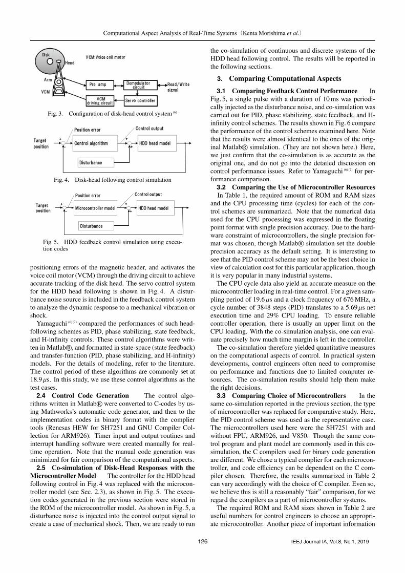
Control The configuration of the HDD disk-head con-trol system is shown in Fig. 3 (6) (7). The magnetic data on thedisk are recorded in concentric circles. Besides the recordeddata, the concentric sectors formed on the disk also pro-vide the location information so that the disk head can trackthem. The demodulator circuit extracts the positional datafor the servo operation from the preamplifier signal. Theservo controller inputs the decoded position signal, calculates
Fig. 2. Microcontroller model
125 IEEJ Journal IA, Vol.8, No.1, 2019
Computational Aspect Analysis of Real-Time Systems(Kenta Morishima et al.)
Fig. 3. Configuration of disk-head control system (6)
Fig. 4. Disk-head following control simulation
Fig. 5. HDD feedback control simulation using execu-tion codes
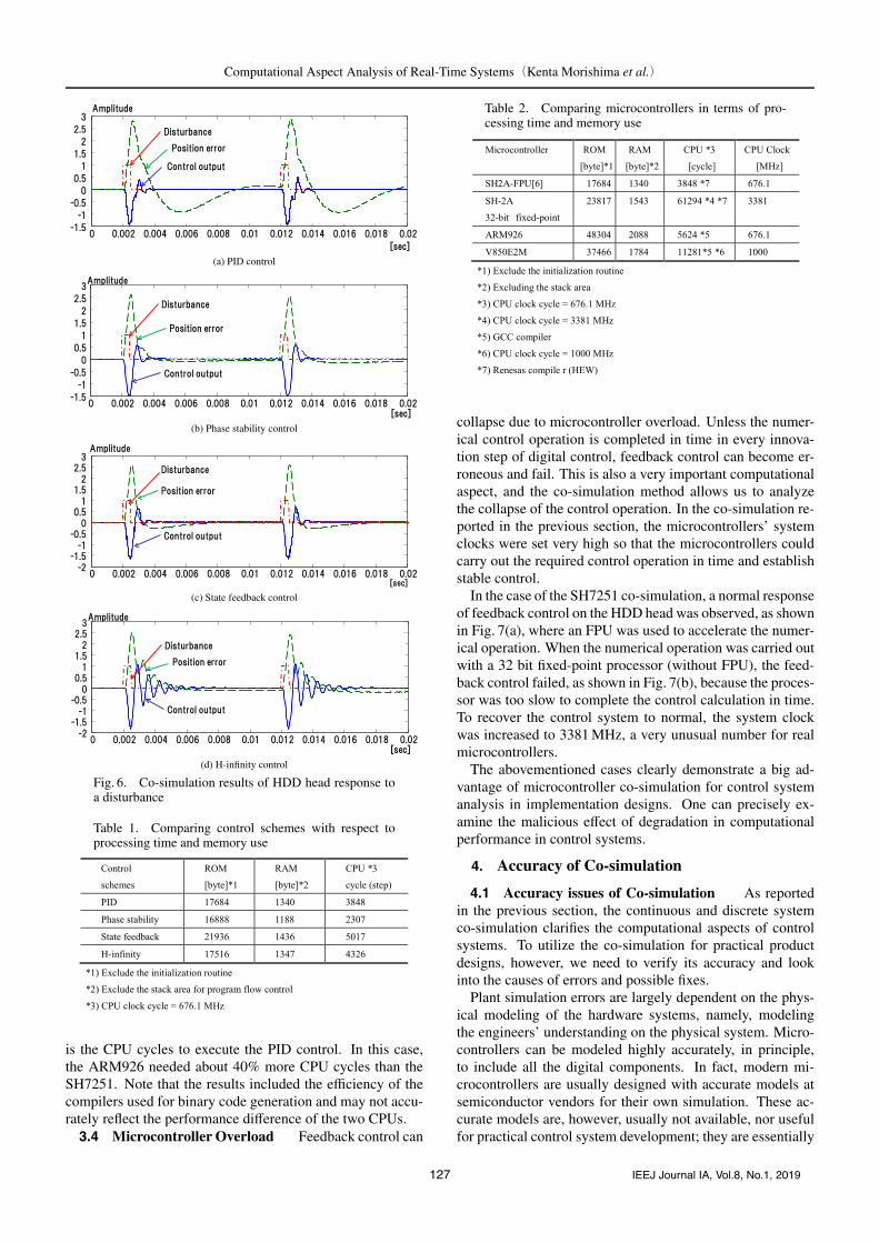
positioning errors of the magnetic header, and activates thevoice coil motor (VCM) through the driving circuit to achieveaccurate tracking of the disk head. The servo control systemfor the HDD head following is shown in Fig. 4. A distur-bance noise source is included in the feedback control systemto analyze the dynamic response to a mechanical vibration orshock.
Yamaguchi (6) (7) compared the performances of such head-following schemes as PID, phase stabilizing, state feedback,and H-infinity controls. These control algorithms were writ-ten in Matlab R©, and formatted in state-space (state feedback)and transfer-function (PID, phase stabilizing, and H-infinity)models. For the details of modeling, refer to the literature.The control period of these algorithms are commonly set at18.9 µs. In this study, we use these control algorithms as thetest cases.2.4 Control Code Generation The control algo-
rithms written in Matlab R© were converted to C-codes by us-ing Mathworks’s automatic code generator, and then to theimplementation codes in binary format with the compliertools (Renesas HEW for SH7251 and GNU Compiler Col-lection for ARM926). Timer input and output routines andinterrupt handling software were created manually for real-time operation. Note that the manual code generation wasminimized for fair comparison of the computational aspects.2.5 Co-simulation of Disk-Head Responses with the
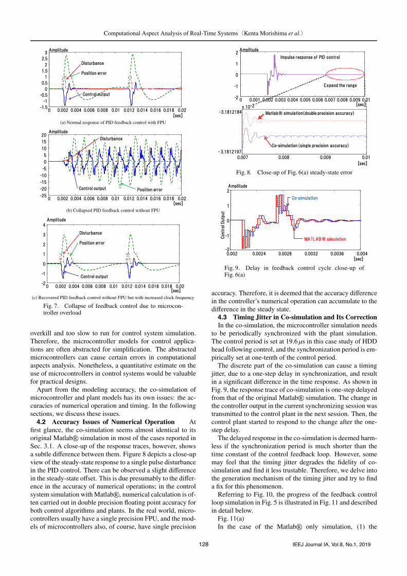
Microcontroller Model The controller for the HDD headfollowing control in Fig. 4 was replaced with the microcon-troller model (see Sec. 2.3), as shown in Fig. 5. The execu-tion codes generated in the previous section were stored inthe ROM of the microcontroller model. As shown in Fig. 5, adisturbance noise is injected into the control output signal tocreate a case of mechanical shock. Then, we are ready to run
the co-simulation of continuous and discrete systems of theHDD head following control. The results will be reported inthe following sections.
3. Comparing Computational Aspects
3.1 Comparing Feedback Control Performance InFig. 5, a single pulse with a duration of 10 ms was periodi-cally injected as the disturbance noise, and co-simulation wascarried out for PID, phase stabilizing, state feedback, and H-infinity control schemes. The results shown in Fig. 6 comparethe performance of the control schemes examined here. Notethat the results were almost identical to the ones of the orig-inal Matlab R© simulation. (They are not shown here.) Here,we just confirm that the co-simulation is as accurate as theoriginal one, and do not go into the detailed discussion oncontrol performance issues. Refer to Yamaguchi (6) (7) for per-formance comparison.3.2 Comparing the Use of Microcontroller ResourcesIn Table 1, the required amount of ROM and RAM sizes
and the CPU processing time (cycles) for each of the con-trol schemes are summarized. Note that the numerical dataused for the CPU processing was expressed in the floatingpoint format with single precision accuracy. Due to the hard-ware constraint of microcontrollers, the single precision for-mat was chosen, though Matlab R© simulation set the doubleprecision accuracy as the default setting. It is interesting tosee that the PID control scheme may not be the best choice inview of calculation cost for this particular application, thoughit is very popular in many industrial systems.
The CPU cycle data also yield an accurate measure on themicrocontroller loading in real-time control. For a given sam-pling period of 19.6 µs and a clock frequency of 676 MHz, acycle number of 3848 steps (PID) translates to a 5.69 µs netexecution time and 29% CPU loading. To ensure reliablecontroller operation, there is usually an upper limit on theCPU loading. With the co-simulation analysis, one can eval-uate precisely how much time margin is left in the controller.
The co-simulation therefore yielded quantitative measureson the computational aspects of control. In practical systemdevelopments, control engineers often need to compromiseon performance and functions due to limited computer re-sources. The co-simulation results should help them makethe right decisions.3.3 Comparing Choice of Microcontrollers In the
same co-simulation reported in the previous section, the typeof microcontroller was replaced for comparative study. Here,the PID control scheme was used as the representative case.The microcontrollers used here were the SH7251 with andwithout FPU, ARM926, and V850. Though the same con-trol program and plant model are commonly used in this co-simulation, the C compilers used for binary code generationare different. We chose a typical complier for each microcon-troller, and code efficiency can be dependent on the C com-piler chosen. Therefore, the results summarized in Table 2can vary accordingly with the choice of C compiler. Even so,we believe this is still a reasonably “fair” comparison, for weregard the compilers as a part of microcontroller systems.
The required ROM and RAM sizes shown in Table 2 areuseful numbers for control engineers to choose an appropri-ate microcontroller. Another piece of important information
126 IEEJ Journal IA, Vol.8, No.1, 2019
Computational Aspect Analysis of Real-Time Systems(Kenta Morishima et al.)
(a) PID control
(b) Phase stability control
(c) State feedback control
(d) H-infinity control
Fig. 6. Co-simulation results of HDD head response toa disturbance
Table 1. Comparing control schemes with respect toprocessing time and memory use
is the CPU cycles to execute the PID control. In this case,the ARM926 needed about 40% more CPU cycles than theSH7251. Note that the results included the efficiency of thecompilers used for binary code generation and may not accu-rately reflect the performance difference of the two CPUs.3.4 Microcontroller Overload Feedback control can
Table 2. Comparing microcontrollers in terms of pro-cessing time and memory use
collapse due to microcontroller overload. Unless the numer-ical control operation is completed in time in every innova-tion step of digital control, feedback control can become er-roneous and fail. This is also a very important computationalaspect, and the co-simulation method allows us to analyzethe collapse of the control operation. In the co-simulation re-ported in the previous section, the microcontrollers’ systemclocks were set very high so that the microcontrollers couldcarry out the required control operation in time and establishstable control.
In the case of the SH7251 co-simulation, a normal responseof feedback control on the HDD head was observed, as shownin Fig. 7(a), where an FPU was used to accelerate the numer-ical operation. When the numerical operation was carried outwith a 32 bit fixed-point processor (without FPU), the feed-back control failed, as shown in Fig. 7(b), because the proces-sor was too slow to complete the control calculation in time.To recover the control system to normal, the system clockwas increased to 3381 MHz, a very unusual number for realmicrocontrollers.
The abovementioned cases clearly demonstrate a big ad-vantage of microcontroller co-simulation for control systemanalysis in implementation designs. One can precisely ex-amine the malicious effect of degradation in computationalperformance in control systems.
4. Accuracy of Co-simulation
4.1 Accuracy issues of Co-simulation As reportedin the previous section, the continuous and discrete systemco-simulation clarifies the computational aspects of controlsystems. To utilize the co-simulation for practical productdesigns, however, we need to verify its accuracy and lookinto the causes of errors and possible fixes.
Plant simulation errors are largely dependent on the phys-ical modeling of the hardware systems, namely, modelingthe engineers’ understanding on the physical system. Micro-controllers can be modeled highly accurately, in principle,to include all the digital components. In fact, modern mi-crocontrollers are usually designed with accurate models atsemiconductor vendors for their own simulation. These ac-curate models are, however, usually not available, nor usefulfor practical control system development; they are essentially
127 IEEJ Journal IA, Vol.8, No.1, 2019
Computational Aspect Analysis of Real-Time Systems(Kenta Morishima et al.)
(a) Normal response of PID feedback control with FPU
(b) Collapsed PID feedback control without FPU
(c) Recovered PID feedback control without FPU but with increased clock frequency
Fig. 7. Collapse of feedback control due to microcon-troller overload
overkill and too slow to run for control system simulation.Therefore, the microcontroller models for control applica-tions are often abstracted for simplification. The abstractedmicrocontrollers can cause certain errors in computationalaspects analysis. Nonetheless, a quantitative estimate on theuse of microcontrollers in control systems would be valuablefor practical designs.
Apart from the modeling accuracy, the co-simulation ofmicrocontroller and plant models has its own issues: the ac-curacies of numerical operation and timing. In the followingsections, we discuss these issues.4.2 Accuracy Issues of Numerical Operation At
first glance, the co-simulation seems almost identical to itsoriginal Matlab R© simulation in most of the cases reported inSec. 3.1. A close-up of the response traces, however, showsa subtle difference between them. Figure 8 depicts a close-upview of the steady-state response to a single pulse disturbancein the PID control. There can be observed a slight differencein the steady-state offset. This is due presumably to the differ-ence in the accuracy of numerical operations; in the controlsystem simulation with Matlab R©, numerical calculation is of-ten carried out in double precision floating point accuracy forboth control algorithms and plants. In the real world, micro-controllers usually have a single precision FPU, and the mod-els of microcontrollers also, of course, have single precision
Fig. 8. Close-up of Fig. 6(a) steady-state error
Fig. 9. Delay in feedback control cycle close-up ofFig. 6(a)
accuracy. Therefore, it is deemed that the accuracy differencein the controller’s numerical operation can accumulate to thedifference in the steady state.4.3 Timing Jitter in Co-simulation and Its CorrectionIn the co-simulation, the microcontroller simulation needs
to be periodically synchronized with the plant simulation.The control period is set at 19.6µs in this case study of HDDhead following control, and the synchronization period is em-pirically set at one-tenth of the control period.
The discrete part of the co-simulation can cause a timingjitter, due to a one-step delay in synchronization, and resultin a significant difference in the time response. As shown inFig. 9, the response trace of co-simulation is one-step delayedfrom that of the original Matlab R© simulation. The change inthe controller output in the current synchronizing session wastransmitted to the control plant in the next session. Then, thecontrol plant started to respond to the change after the one-step delay.
The delayed response in the co-simulation is deemed harm-less if the synchronization period is much shorter than thetime constant of the control feedback loop. However, somemay feel that the timing jitter degrades the fidelity of co-simulation and find it less trustable. Therefore, we delve intothe generation mechanism of the timing jitter and try to finda fix for this phenomenon.
Referring to Fig. 10, the progress of the feedback controlloop simulation in Fig. 5 is illustrated in Fig. 11 and describedin detail below.
Fig. 11(a)In the case of the Matlab R© only simulation, (1) the
128 IEEJ Journal IA, Vol.8, No.1, 2019

Computational Aspect Analysis of Real-Time Systems(Kenta Morishima et al.)
Fig. 10. Cause of the timing jitter in the co-simulation
(a) Matlab R© only
(b) Co-simulation Case 1
(c) Co-simulation Case 2
Fig. 11. Time chart showing the cause of the timing jitter
controller first detects the change in the error signal, (2) thenit calculates the control outputs according to its specified con-trol scheme, and (3) its output is fed to the control plant,i.e., the VCM. The above steps of (1)–(3) are repeated pe-riodically in every sampling period, which is specified to be19.6 µs in this particular case.
Fig. 11(b)In the case of co-simulation, (4) the microcontroller first
detects the change in the error signal, (5) then it executes thecontrol program which realizes the specified control scheme,and calculates the control outputs. The control program istriggered at every sampling period of 19.6 µs by using a timercounter interrupt which is integrated in the microcontroller.(6) Finally, the output is fed to the control plant.
Fig. 11(c)As the control program execution is triggered by the hard-
ware timer model and is independent from the sampling pe-riod, it can start at any time in the sampling period. In the caseof Fig. 11(b), the control program execution is completed inthe same control step as in Fig. 11(a). However, in Fig. 11(c),
Fig. 12. Synchronization adaptor
Fig. 13. Synchronization adaptor timing chart
the control output is not updated until the next control step,due to the late trigger timing. Therefore, the updated con-trol output is fed to the control plant with a one-step delay,causing a timing jitter as shown in Fig. 9.
To correct the timing jitter in the co-simulation, we pro-posed the method of synchronization adaptor shown inFig. 12. The synchronization adaptor is a pair of circuits:a synchronization pulse generator and an external interruptport. The synchronization pulse is generated by the plantmodel simulator at the beginning of each sampling period.The pulse is fed to the external interrupt port and initiates thecontrol program. Thus, the two simulators are synchronizedat the beginning of the sampling period.
The timing chart with the synchronization adaptor is shownin Fig. 13. Because the synchronization pulse is transferredto the microcontroller in the next synchronization period, thetiming jitter is eliminated, as shown in Fig. 8.
5. Conclusion
In this study, we analyzed the computational aspects ofan HDD head following control as an example case. Co-simulation of the continuous control plant and discrete mi-crocontroller was introduced. The microcontroller model in-cluded the CPU, which ran implementation codes of con-trol programs, and many other peripheral functions, such astimer units, interrupt controllers, and analog interfaces. Theco-simulation results detailed the memory use and compu-tational load for each of the control algorithms examined.Different types of microcontrollers were tested by the co-simulation for a comparative study. One can select an ap-propriate microcontroller for a particular control application.The accuracy of the co-simulation was discussed in termsof numerical operation and timing jitters. To correct anytiming issues of the co-simulation, a synchronization adap-tor approach was proposed and verified. Overall, the pro-posed co-simulation method was proved to be useful for
Matlab R© a trademark of the MathWorks, Inc.Modelica R© is a trade mark of the Modelica Design GroupCoMET-METeor R© is a trade mark of the Synopsys, Inc.
129 IEEJ Journal IA, Vol.8, No.1, 2019
Computational Aspect Analysis of Real-Time Systems(Kenta Morishima et al.)
computational aspect analysis of real-time control systems.The timing accuracy, jitter elimination, and synchroniza-
tion of multiple simulators in co-simulation are still unre-solved issues in the proposed real-time system analysis ap-proach. Establishing a reliable co-simulation environment isstill an enormous challenge for control application engineers.The proposed co-simulation technique needs to be further ex-amined by control designers and real-time system integratorsto draw the maximum benefit from the continuous and dis-crete hybrid simulation technology.
References
( 1 ) M. Hirata, M. Takiguchi, and K. Nonami: “Track-Following Control of HardDisk Drives Using Multi-Rate Sampled-Data H∞ Control”, Proc. of the IEEEConference on Decision and Control, Maui, Hawaii USA (2003)
( 2 ) K. Ohno and S. Hara: “A Temperature-Dependent Multi-Rate Robust Con-troller for Hard Disk Drives”, SICE Transactions on Industrial Applications,Vol.5, No.9, pp.57–65 (2006)
( 3 ) J. Zheng, M. Wang, and C. Du: “Nonlinear Tracking Control for a Hard DiskDrive Dual-Stage Actuator System”, IEEE/ASME Transactions on Mecha-tronics, Vol.13, No.5, pp.510–518 (2008)
( 4 ) T. Atsumi: “Emerging Technology for Head-Positioning System in HDDs”,IEEJ Journal of Industry Applications, Vol.5, No.2, pp.117–112 (2016)
( 5 ) T. Atsumi: “Estimation Method of Unobservable Oscillations in Sampled-Data Positioning Systems”, IEEJ Journal of Industry Applications, Vol.6,No.3, pp.199–204 (2017)
( 6 ) T. Yamaguchi, M. Hirata, and H. Fujimoto: “Nanoscale Servo Control”,Tokyo Denki University Press (2007) (in Japanese)
( 7 ) T. Yamaguchi, M. Hirata, and C.K. Pang: “Advances in High-PerformanceMotion Control of Mechatronic Systems”, CRC Press (2013)
( 8 ) T. Atsumi: “Shock-Response-Spectrum Analysis of Sampled-Data Polyno-mial for Track-Seeking Control in Hard Disk Drives”, Proc. of the IEEE In-ternational Workshop on Advanced Motion Control, pp.240–247 (2008)
( 9 ) Q.W. Jia: “New Design of Multirate Digital Control Scheme for ComputationSaving”, IEEE International Conference on Industrial Technology, pp.1–4(2008)
(10) M. Ishikawa, D.J. McCune, G. Saikalis, and S. Oho: “CPU Model-basedHardware/Software Co-design for Real-Time Embedded Control Systems”,SAE World Congress 2007-01-0776 (2007)
(11) Y. Sugure, S. Oho, S.S. Phatak, and G. Saikalis: “Virtual Engine Sys-tem Prototyping with High-Resolution FFT for Digital Knock DetectionUsing CPU Model-Based Hardware/Software Co-simulation”, SAE WorldCongress 2009-01-0532 (2009)
Kenta Morishima (Non-member) graduated from Tokyo universityof Agriculture and Technology in 1990, received B.E.and received M.E. in 1992. He joined Hitachi, Ltd.in 1992 and then worked at central research labora-tories. Now he works at Research & DevelopmentGroup, Hitachi, Ltd., Tokyo, Japan. Morishima is amember of SAE.
Shigeru Oho (Member) graduated from National Institute of Tech-nology, Sasebo college and received BE from Uni-versity of Electro-Communications, M.E. and Ph.D.from Tokyo Institute of Technology in 1976, 1978,1980, 1997, respectively. He joined Hitachi, Ltd. in1980 and worked at its R&D divisions in Japan andthe USA. From 1986 to 1987 he was a visiting scien-tist at Massachusetts Institute of Technology. Since2012 he has been a professor at Nippon Institute ofTechnology. Dr. Oho is a member of IEEJ, IEICE,
SICE, ISCIE, IEEE, SAEJ, and SAE.
130 IEEJ Journal IA, Vol.8, No.1, 2019