computer graphics - viewing - hanyang university jong-il park
TRANSCRIPT
Computer GraphicsComputer Graphics- Viewing -- Viewing -
Hanyang University
Jong-Il Park

Division of Electrical and Computer Engineering, Hanyang University
ObjectivesObjectives
Classical viewing Introduce the classical views Compare and contrast image formation by computer
with how images have been formed by architects, artists, and engineers
Learn the benefits and drawbacks of each type of view
Computer viewing Introduce the mathematics of projection Introduce OpenGL viewing functions Look at alternate viewing APIs
Division of Electrical and Computer Engineering, Hanyang University
Classical ViewingClassical Viewing
Viewing requires three basic elements One or more objects A viewer with a projection surface Projectors that go from the object(s) to the projection
surface Classical views are based on the relationship among
these elements The viewer picks up the object and orients it how she
would like to see it Each object is assumed to constructed from flat
principal faces Buildings, polyhedra, manufactured objects

Division of Electrical and Computer Engineering, Hanyang University
Planar Geometric ProjectionsPlanar Geometric Projections
Standard projections project onto a plane Projectors are lines that either
converge at a center of projection or are parallel
Such projections preserve lines but not necessarily angles
Nonplanar projections are needed for applications such as map construction

Division of Electrical and Computer Engineering, Hanyang University
Classical ProjectionsClassical Projections

Division of Electrical and Computer Engineering, Hanyang University
Perspective vs ParallelPerspective vs Parallel
Computer graphics treats all projections the same and implements them with a single pipeline
Classical viewing developed different techniques for drawing each type of projection
Fundamental distinction is between parallel and perspective viewing even though mathematically parallel viewing is the limit of perspective viewing

Division of Electrical and Computer Engineering, Hanyang University
Taxonomy of Planar Geometric Taxonomy of Planar Geometric ProjectionsProjections
parallel perspective
axonometric multivieworthographic
oblique
isometric dimetric trimetric
2 point1 point 3 point
planar geometric projections

Division of Electrical and Computer Engineering, Hanyang University
Perspective ProjectionPerspective Projection
Division of Electrical and Computer Engineering, Hanyang University
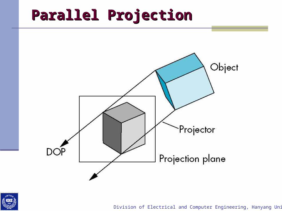
Parallel ProjectionParallel Projection

Division of Electrical and Computer Engineering, Hanyang University
Orthographic ProjectionOrthographic Projection
Projectors are orthogonal to projection surface

Division of Electrical and Computer Engineering, Hanyang University
Multiview Orthographic ProjectionMultiview Orthographic Projection
Projection plane parallel to principal face Usually form front, top, side views
isometric (not multivieworthographic view)
front
sidetop
in CAD and architecture, we often display three multiviews plus isometric
Division of Electrical and Computer Engineering, Hanyang University
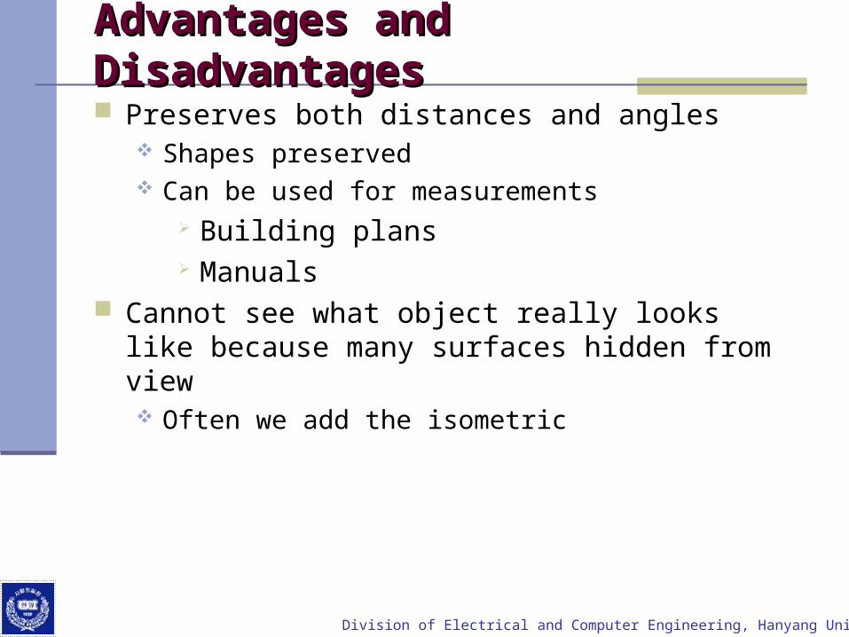
Advantages and DisadvantagesAdvantages and Disadvantages
Preserves both distances and angles Shapes preserved Can be used for measurements
Building plans Manuals
Cannot see what object really looks like because many surfaces hidden from view Often we add the isometric
Division of Electrical and Computer Engineering, Hanyang University
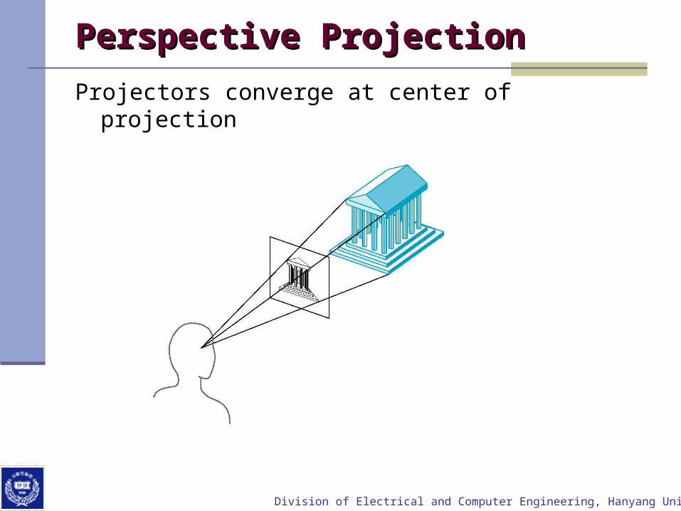
Perspective ProjectionPerspective Projection
Projectors converge at center of projection
Division of Electrical and Computer Engineering, Hanyang University
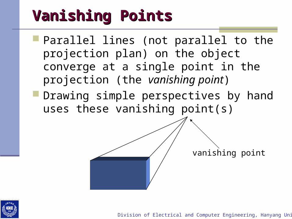
Vanishing PointsVanishing Points
Parallel lines (not parallel to the projection plan) on the object converge at a single point in the projection (the vanishing point)
Drawing simple perspectives by hand uses these vanishing point(s)
vanishing point

Division of Electrical and Computer Engineering, Hanyang University
Three-Point PerspectiveThree-Point Perspective
No principal face parallel to projection plane Three vanishing points for cube

Division of Electrical and Computer Engineering, Hanyang University
Two-Point PerspectiveTwo-Point Perspective
On principal direction parallel to projection plane
Two vanishing points for cube
Division of Electrical and Computer Engineering, Hanyang University
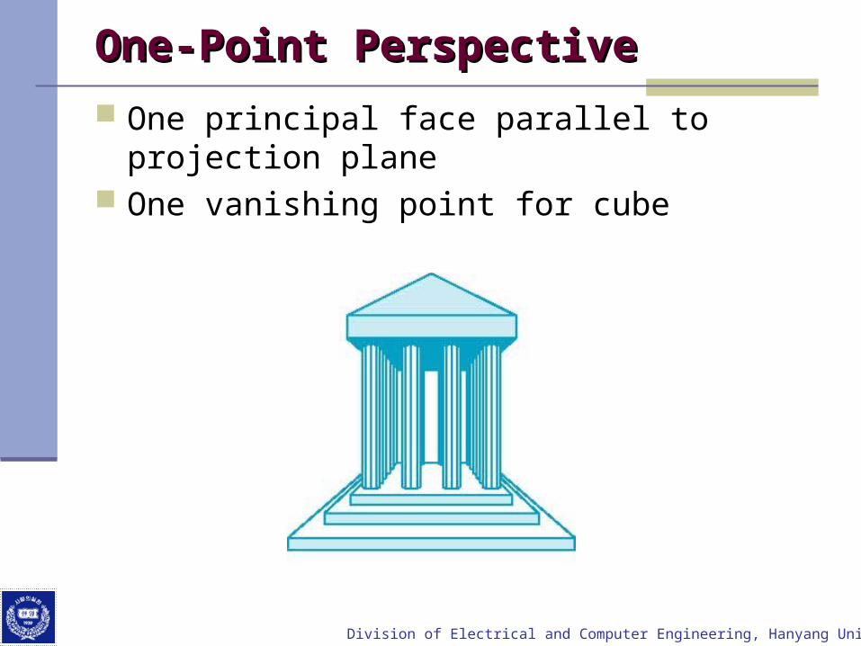
One-Point Perspective One-Point Perspective
One principal face parallel to projection plane One vanishing point for cube
Division of Electrical and Computer Engineering, Hanyang University
Advantages and DisadvantagesAdvantages and Disadvantages
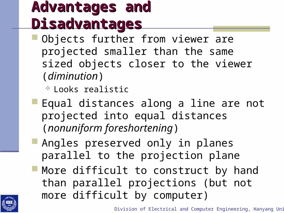
Objects further from viewer are projected smaller than the same sized objects closer to the viewer (diminution) Looks realistic
Equal distances along a line are not projected into equal distances (nonuniform foreshortening)
Angles preserved only in planes parallel to the projection plane
More difficult to construct by hand than parallel projections (but not more difficult by computer)

Division of Electrical and Computer Engineering, Hanyang University
Computer ViewingComputer Viewing
There are three aspects of the viewing process, all of which are implemented in the pipeline, Positioning the camera
Setting the model-view matrix Selecting a lens
Setting the projection matrix Clipping
Setting the view volume

Division of Electrical and Computer Engineering, Hanyang University
The OpenGL CameraThe OpenGL Camera
In OpenGL, initially the object and camera frames are the same Default model-view matrix is an identity
The camera is located at origin and points in the negative z direction
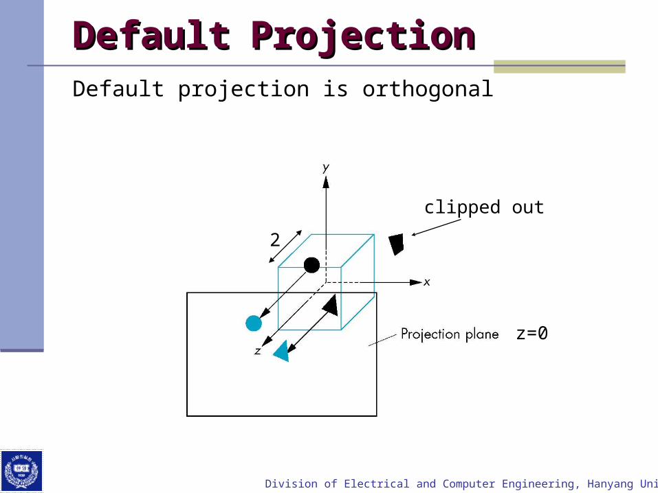
OpenGL also specifies a default view volume that is a cube with sides of length 2 centered at the origin Default projection matrix is an identity
Division of Electrical and Computer Engineering, Hanyang University
DefaultDefault ProjectionProjectionDefault projection is orthogonal
clipped out
z=0
2

Division of Electrical and Computer Engineering, Hanyang University
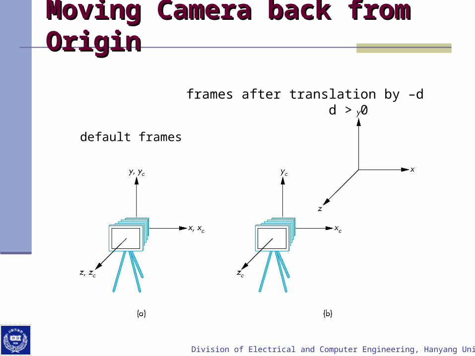
Moving the Camera FrameMoving the Camera Frame
If we want to visualize object with both positive and negative z values we can either Move the camera in the positive z direction
Translate the camera frame Move the objects in the negative z direction
Translate the world frame Both of these views are equivalent and are determined
by the model-view matrix Want a translation (glTranslatef(0.0,0.0,-d);) d > 0
Division of Electrical and Computer Engineering, Hanyang University
Moving Camera back from Origin Moving Camera back from Origin
default frames
frames after translation by –d d > 0
Division of Electrical and Computer Engineering, Hanyang University
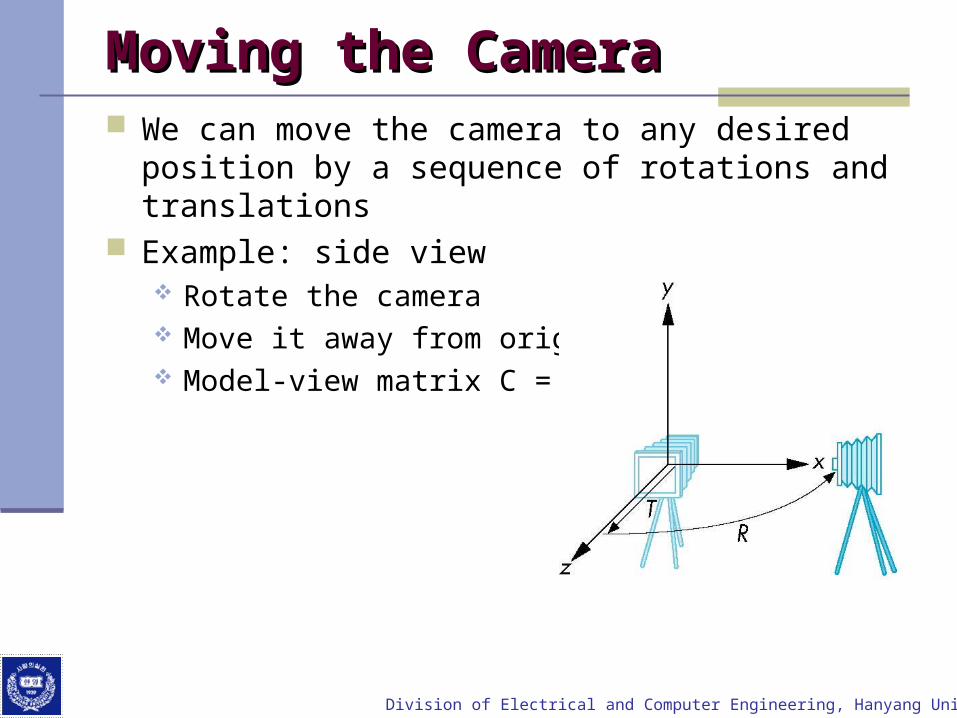
Moving the CameraMoving the Camera We can move the camera to any desired position by
a sequence of rotations and translations Example: side view
Rotate the camera Move it away from origin Model-view matrix C = TR

Division of Electrical and Computer Engineering, Hanyang University
OpenGL codeOpenGL code
Remember that last transformation specified is first to be applied
glMatrixMode(GL_MODELVIEW)glLoadIdentity();glTranslatef(0.0, 0.0, -d);glRotatef(90.0, 0.0, 1.0, 0.0);

Division of Electrical and Computer Engineering, Hanyang University
The LookAt FunctionThe LookAt Function
The GLU library contains the function gluLookAt to form the required modelview matrix through a simple interface
Note the need for setting an up direction Still need to initialize
Can concatenate with modeling transformations
Example: isometric view of cube aligned with axes
glMatrixMode(GL_MODELVIEW):glLoadIdentity();gluLookAt(1.0, 1.0, 1.0, 0.0, 0.0, 0.0, 0.0, 1.0. 0.0);

Division of Electrical and Computer Engineering, Hanyang University
gluLookAtgluLookAt
glLookAt(eyex, eyey, eyez, atx, aty, atz, upx, upy, upz)
Division of Electrical and Computer Engineering, Hanyang University
Other Viewing APIsOther Viewing APIs The LookAt function is only one possible API for
positioning the camera Others include
View reference point, view plane normal, view up (PHIGS, GKS-3D)
Yaw, pitch, roll Elevation, azimuth, twist Direction angles

Division of Electrical and Computer Engineering, Hanyang University
Projections and NormalizationProjections and Normalization
The default projection in the eye (camera) frame is orthogonal
For points within the default view volume
Most graphics systems use view normalization All other views are converted to the default view by
transformations that determine the projection matrix Allows use of the same pipeline for all views
xp = xyp = yzp = 0

Division of Electrical and Computer Engineering, Hanyang University
Homogeneous Coordinate Homogeneous Coordinate RepresentationRepresentation
xp = xyp = yzp = 0wp = 1
pp = Mp
M =
1000
0000
0010
0001
In practice, we can let M = I and set the z term to zero later
default orthographic projection

Division of Electrical and Computer Engineering, Hanyang University
Simple PerspectiveSimple Perspective Center of projection at the origin Projection plane z = d, d < 0

Division of Electrical and Computer Engineering, Hanyang University
Perspective EquationsPerspective Equations
Consider top and side views
xp = dz
x
/yp = dz
y
/zp = d

Division of Electrical and Computer Engineering, Hanyang University
Homogeneous Coordinate FormHomogeneous Coordinate Form
M =
0/100
0100
0010
0001
d
consider q = Mp where
1
z
y
x
dz
z
y
x
/
p = q =
Division of Electrical and Computer Engineering, Hanyang University
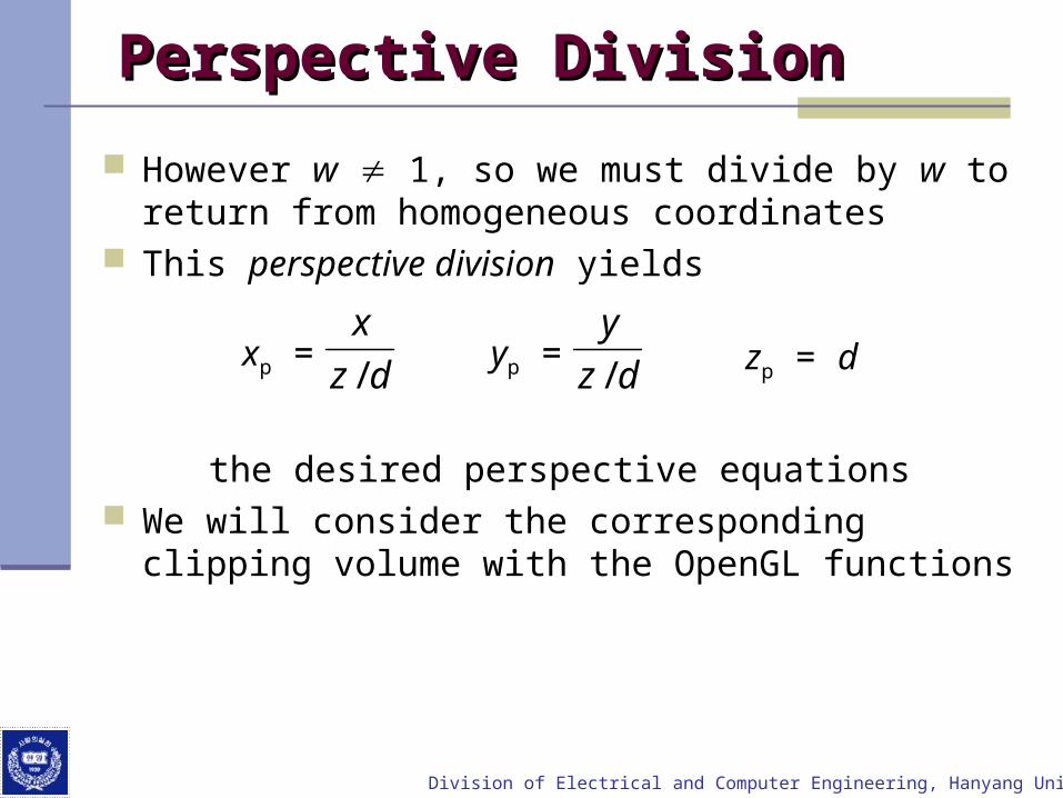
Perspective DivisionPerspective Division
However w 1, so we must divide by w to return from homogeneous coordinates
This perspective division yields
the desired perspective equations We will consider the corresponding clipping volume with
the OpenGL functions
xp = dz
x
/yp = dz
y
/ zp = d

Division of Electrical and Computer Engineering, Hanyang University
OpenGL Orthogonal ViewingOpenGL Orthogonal Viewing
glOrtho(left,right,bottom,top,near,far)
near and far measured from camera

Division of Electrical and Computer Engineering, Hanyang University
OpenGL PerspectiveOpenGL Perspective
glFrustum(left,right,bottom,top,near,far)

Division of Electrical and Computer Engineering, Hanyang University
Using Field of ViewUsing Field of View
With glFrustum it is often difficult to get the desired view
gluPerpective(fovy, aspect, near, far) often provides a better interface
aspect = w/h
front plane