computer networks - introduction network management architectures
TRANSCRIPT

Computer Networks - Introduction Network Management Architectures &
Applications Network Management
1

2
Week Topic
Week 1 Computer Networks - Network Management Architectures & Applications
Week 2 Network Management Standards Architectures & Applications
Week 3 Simple Network Management Protocol - SNMP v1, ASN, MIB, BER
Week 4 Network Management Functions - Fault
Week 5 Simple Network Management Protocol - SNMP v2 - Configuration
Week 6 Network Management Functions - Accounting
Week 7 Simple Network Management Protocol - SNMP v3 - Performance
Week 8 Network Management Functions - Security
Week 9 Midterm
Week 10 Remote Network Monitoring RMON 1, SLA
Week 11 Remote Network Monitoring RMON 2
Week 12 Management Tools, Systems and Applications
Week 13 NM Project Presentations
Week 14 NM Project Presentations
Week 15 NM Project Presentations
Lectures Schedule

Introduction
• The second industrial revolution radically changes the way we communicate virtually eliminating information lag.
• What problems does this create?
3

Recent Communications History
• 1834 Samuel Morse invents the telegraph
• 1876 Alexander Graham Bell makes the first long-distance phone call (10 miles)
• 1915 First transatlantic and transcontinental telephone service.
• 1948 Microwave links for telephone calls
• 1951 direct long distance dialing
4

Communications History Cont.
• 1962 Fax service is introduced
• 1965 widespread use of satellite long distance.
• 1968 Non Bell equipment allowed on phones system
• 1969 Picturephones
• 1969 DARPAnet
5

Communications History Cont.
• 1970 Limited long-distance competition allowed
• 1984 AT&T is broken up creating a regulatory boundary between local phone service and long distance
• 1984 Cellular phone service starts
• 1990’s Cellular phone service explodes
6

Communications History Cont.
• 1996 Telecommunications Competition and Deregulation Act replaced all federal and state telecommunications law
• 1997 68 countries sign agreement to allow foreign telecommunications competition
7

Information Systems History
• 1950’s Batch processing and punch cards
• 1970’s Real-time transaction-oriented database-driven systems emerge
• 1990’s Macys is bankrupt in part due to their “old” 1970’s era IS infrastructure
• Read comparison between Macys and WalMart
8

Components of a Network
• Server – a device that stores data and often performs functions in addition to storage
• Client – A terminal or microcomputer from which a user or other application performs a work function
• Circuit – a wire, or set of wires and devices (modem, router, switch etc…) that carry information from the client to the server
9

Types of Networks
• LAN – Local Area Network
• BN – Backbone Network
• MAN – Metropolitan Network
• WAN – Wide Area Network
• Intranet – A network used within an organization
• Extranet – Access for people from outside
10

Network Models
• Used to break networks into component functions (layers) which then allows each layer to be addressed independently.
• The use of layers and different standards (and standards bodies) at these layers allows great flexibility in design, and competition between manufacturers.
11

OSI Model
• Produced in 1984
• Consists of seven layers
12

Internet Model
• Similar to the OSI model
• Compresses layers 5-7 into a single layer 5
• The textbook author claims the internet model has won the “war”. Is this true?
13

Functions at Layer 4 (TCP)
• Error detection/correction
• Linking higher layer software to the network layer
• Name resolution
• Breaking messages into pieces small enough to send over the network (MTU
14

Functions at Layer 3 (IP)
• Responsible for end-to-end routing of messages from sender to receiver
• Responsible for attaining the next address for messages as they hop from router to router across the internet
15
Functions at Layer 2
• Responsible for moving messages from the sender to the receiver within a LAN.
• Controls the physical layer
• Formats the messages
• Provides error detection and correction
16

Functions at Layer 1
• Get the signal (electrical signal, light pulse, smoke signal) from one LAN device to the next.
• This layer includes hardware devices such as modems and hubs.
17

Two Types of Standards
• Formal
– Developed by an official industry or government agency
– These are often slow in developing and follow an already existing de facto standard
• De facto
– Emerge in the marketplace and are supported by multiple vendors but have to official standing
18

Standards Making Bodies
• IEEE
– The Institute of Electrical and Electronic Engineers
– Professional organization based in the United States
– Primarily responsible for existing LAN standards
19

Standards Making Bodies
• ITU-T
– Responsible for creating technical standards for the united nations international telecommunications union (ITU)
– Open to public or private operators of communications networks from more then 200 countries
– Based in Geneva Switzerland
20

Standards Making Bodies
• IETF
– Internet Engineering Task Force
– Open to everyone
– Manages consensus-building process through the use of RFC’s
– Oversees creation of Internet protocols and standards
21

Future Trends
• Pervasive networking
• Integration of voice, video and data
• New information services
22

Application Architectures
• Host-Based Architectures
– Commonly a mainframe with terminals
• Client-Based Architectures
– Distribute PC based architecture with the computing power at the desktop
• Client-Server Architecture
– Applications software divided between desktop PC’s and central servers (fat vs. thin clients)
23

N-tier Architectures
• Two-tier – A client talks to a server (connecting to a web
server)
• Three-tier – A client talks to a web server which in turns
queries a database server to obtain the requested data
• N-tier – Same concept applied N times
24

Advantages of Client-Server
• Scalability
– N-tiered architecture gives a high degree of scalability
• Cost of infrastructure
– A set of smaller micro or mini computers and the associated software is often far less expensive then a mainframe approach
25

World Wide Web
• Create in 1989 at the CERN lab in Geneva Switzerland by Tim Berners-Lee
• A graphical interface was developed in 1993 by a team of students led by Marc Andreessen at the NCSA lab at the University of Illinois
• Adoption of the technology was immediate and rapid
26

Electronic Mail
• One of the earliest applications on the Internet (Early “killer” app)
• Cost and speed are among it’s strengths when compared with “snail mail”
• Important protocols and extensions to understand – SMTP (Simple Mail Transfer Protocol)
– IMAP (Internet Message Access Protocol)
– MIME (Multipurpose Internet Mail Extension)
27
Other Important Applications
• FTP – File Transfer Protocol
– Provides the ability to transfer data to and from systems (primarily used in conjunction with UNIX servers)
• Telnet
– Provides the ability to login to a server from anywhere within a connected network
– The name is derived from making a TELephone connection via the NETwork.
28

Components in Physical Layer
• Media
– Wires, fiber-optic strands
– Wireless
• Special-purpose devices
– Modems
– Repeaters/hubs
29
Circuits
• Physical Circuit – Twisted pair cable, fiber, wireless link
– Exclusively committed to your data
• Logical Circuit – One of several, perhaps many circuits on a single
physical circuit
– Channel 12 on TV is a logical circuit, it rides on a coaxial cable or wireless (a physical circuit) along with many other logical circuits
30

Types of Data
• Digital – Two possible values for any data bit (1 or 0)
– In a fiber circuit a light being on could represent a “1” while off represents a “0”
– In a copper circuit 5 volts could represent “1” while 0 volts represents “0”
• Analog – Signals are shaped like sound waves and are
constantly changing
31

Modem/Codec
• MOdulate/DEModulate
– Translates digital data into a form that can be transmitted across an analog circuit such as a standard telephone line
• COder/DECoder
– Translates analog information into a form that can be transmitted across a digital circuit
32

Circuit Configuration
• Point-to-Point
– A circuit with a device at each end
– Home modem
• Multipoint
– A single device at one end with many devices at the other end with either time-slicing or circuit switching
33

Data Flow
• Simplex
– One way transmission (i.e. cable TV)
• Half-duplex
– Communication in both directions, only one way at a time (i.e. walkie-talkie)
• Full-duplex
– Communication in both ways, at the same time (i.e. telephone)
34
Communication Media
• Guided media
– Twisted-pair, coaxial, fiber-optic
• Wireless media
– Radio, infrared, satellite
35

Fiber Optic
• Multi mode
– Attenuation (weakening of the signal)
– Dispersion (spreading of the signal)
• Single mode
– Must use the precision of lasers as opposed to LED’s
36

Coding
• Character
– A symbol with a constant understood meaning
• Byte
– A group of (typically) eight bits that is treated as a character
• ASCII (American Standard Code for Information Interchange)
– 7 or 8 bit code (typically 8)
37

Transmission Modes
• Parallel
– All bits are sent simultaneously, in a 32-bit system then there must be paths to send all 32 bits at the same time
• Serial
– Each bit is sent one at a time,
38

Digital Transmission
• Transmission of 1’s and 0’s
– With electricity this can be voltages with perhaps 0 volts representing a zero and 5 volts representing a 1 (unipolar)
– With light this can be using the state of the light with perhaps off representing a 0 and on representing a 1
39

Manchester Encoding
• Used in Ethernet
• Unipolar coding scheme with a twist
– Voltage moving from a lower level to a higher level represents a “1”
– Voltage moving from high to low is a “0”
40

Analog Transmission
• Telephone systems were originally designed to carry analog transmissions, electrical representations of the human voice
• Three key characteristics
– Amplitude
– Frequency
– Phase
41

Modulation
• A carrier wave (ugly noise heard when modems are negotiating) is sent between modems, the shape of the wave is altered to represent 1’s and 0’s
• These “shape changes” are referred to as modulation
42
Modulation Techniques
• Amplitude
– Modifying the height of the wave
• Frequency
– Modifying the frequency (the number of waves per second) of the wave
• Phase
– Modifying the point in phase at which the wave starts
43
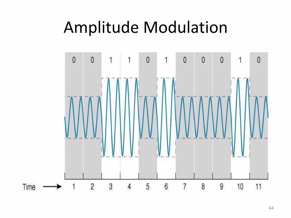
Amplitude Modulation
44

Frequency Modulation
45

Phase Modulation
46

Two-bit Amplitude Modulation
47

Modulation Techniques
• The various modulation techniques discussed can be combined as well
• QAM (Quadrature Amplitude Modulation)
– Combines eight phases (three bits) and two amplitudes (one bit) for a total of four bits
• TCM (Trellis Code Modulation)
– Similar to QAM but can transmit up to ten bits per symbol
48

Bits Baud and Symbol
• Bits (specifically bits per second) are generally the important measurement in data communications as symbols are composed of bits
• There is a common misconception that these terms are interchangeable, baud refers to the number of symbols per second as opposed to the number of bits per second
49

Voice Circuit Capacity
• Home analog phone lines have a bandwidth range from 0 to 4000 Hz
• The human ear can detect sounds up to ~14,000 Hz so very high pitch sounds can’t be transmitted over an analog phone line
• Digital circuits used to tie analog phone lines together have a bandwidth of 64,000 bits per second (bps)
50

Modem Technologies
• V.34+
– Transmits up to 33,600 bps
• V.44 (Compression)
– Builds a dictionary of character combinations being sent over the circuit
– When a combination is repeated the dictionary reference is sent as opposed to the characters
– Average throughput is ~ 6:1
51

Codec
• Converts Analog data into a digital form for transmission over a digital system and back
• The analog signal is translated into a binary number
• This digital signal is an approximation of the original with the quality depending on the resolution by either increasing the amplitude levels or increasing the sampling rate
52

Telephone Transmission
• The “local loop” is the circuit from the phone company CO (the building between 3rd and 4th streets and Chestnut and Hazel streets) uses analog transmission
• Once the signal reaches the phone company office it is converted to digital form and is then sent to it’s destination CO
• Even local calls are converted to digital
53

Pulse Code Modulation
• PCM is used in phone company CODEC’s in North America
• PCM samples the data 8,000 times (twice the highest frequency within the phone system
• Eight bits are generated for each sample, thus the phone system uses the 8 bits * 8,000 samples for a data rate of 64,000 bps
54

ADPCM
• Adaptive Differential Pulse Code Modulation
• Similar to PCM except it only sends the difference between the former and the new signal
• Data rates as low as 8Kbps can be obtained, 32Kbps is the lowest providing sufficient quality so that the user doesn’t notice
• The use of ADPCM is the reason that some users can’t get a modem connection above 26,200 bps
55

Analog/Digital Modems
• Uses PCM backward
• Sends 8,000 samples per second
• Uses 7 bits (one is lost for control purposes
• 7 bits * 8,000 samples = 56,000 bits
• V.92 modems do this in each direction and due to technical constraints are limited to ~52,000 bps downstream and ~42,000 bps upstream
56

Multiplexing
• Using one high-speed circuit to carry the traffic of multiple lower-speed circuits
• FDM
• TDM
• WDM (form of FDM)
• DWM (combination of FDM and TDM)
– Has reached 1.25 terabits already and is expected to reach 1 petabit within a few years
57

Frequency Division Multiplexing
58

Time Division Multiplexing
59

Inverse Multiplexing
• Using a series of lower-speed circuits to connect two high-speed circuits together
• Technology has been proprietary until just recently
• The BONDING (Bandwidth ON Demand Interoperability Networking Group) standard is allowing vendors to interoperate today but this is still in its infancy
60

Inverse Multiplexing
61

Digital Subscriber Line
• Much of the available bandwidth in the local loop has gone unused for many years
• DSL uses this bandwidth by applying FDM to create three circuits comprised of the original phone line, a upstream data circuit and a downstream data circuit
• TDM and PM are also used to obtain various data rates and features
62

Media Access Control
• A mechanism used to control when computers transmit
• Important when using half-duplex circuits or multipoint configurations
• Two fundamental approaches
– Controlled Access
– Contention
63

Controlled Access
• X-ON/X-OFF
• Polling
– Roll Call Polling: one device in the circuit is a “master” and checks with each other device on its wire to see if they have something to say
– Hub Polling (token passing): one computer starts the poll and passes it to the next, when a computer with something to say receives the “token” then it can send its data
64
Contention
• The opposite of controlled access, each device listens to see if someone else is talking, if not then it sends carrier and starts to talk
• CSMA/CD (Carrier Sense Multiple Access with Collision Detection) is used in Ethernet networks
65

Network Errors
• Two types of network errors
– Data loss
– Data corruption
• Three approaches to dealing with errors
– Prevention
– Detection
– Correction
66

Sources of Errors
• Line noise, distortion
• Line outages
• Impulse noise
• Cross-talk
• Attenuation
• Intermodulation noise
• Jitter
67

Error Prevention
• Shielded cabling
• Cable location
• Cable selection (fiber vs. twisted pair)
• Cable installation and maintenance
68

Error Detection
• Parity
• Longitudinal redundancy checking
• Polynomial checking
– Checksum
– Cyclic Redundancy Check
• 16-bit CRC used in TCP
• 32-bit CRC used in Ethernet
69

Error Correction via Retrans.
• Stop-and-wait ARQ
• Continuous ARQ
70

Forward Error Correction
• Sufficient redundant data is included within the transmission to correct errors without retransmission
• Used heavily in satellite transmission
71

Ethernet Protocols
• Ethernet (IEEE 802.3)
– Byte-count protocol
– Destination, length, LLC, SNAP, CRC-32
• Point-to-Point Protocol (PPP)
– Address
– Protocol
– Message length = 1,500 bytes
72

Bridging/Switching
• MAC-layer address table for each interface
• Addresses behind a port are stored in memory
• Ethernet frames are checked at each interface to determine if they should be forwarded
73

Transmission Efficiency
• Transmission efficiency = total information bits/total bits
• Throughput = transmission efficiency adjusted for errors and retransmissions
74

TCP/IP
• TCP
– Layer 4
– Provides error detection (CRC-16)
– Breaks data into appropriate size blocks (MTU)
• IP
– Provides routing and addressing
– IPv4 (32-bit address)
– IPv6 (128-bit address)
75

TCP Ports
• A computer can have multiple applications running, i.e. a machine can be running both a web server and an email server
• Commonly used ports
– SMTP – port 25
– WWW – port 80
– FTP – port 21
– Telnet – port 23
76

77
Encapsulation
Packetizing
• Taking an outgoing message with a length too great to fit within the data-link maximum frame length (MTU) and breaking the message into appropriate lengths
• Function is performed by the transport layer
• With IPv4 the packet size is set for the local LAN and is adjusted if the message is sent across a link that requires a smaller MTU
78

Connection-oriented Routing
• A specific route “virtual route” is determined when the session is created
• A SYN packet is sent to create the virtual circuit
• A FIN packet is sent to tear the circuit down
79

Connectionless Routing
• Uses UDP instead of TCP
• Packets can travel different routes
• Commonly used with applications such as DNS and DHCP which are not likely to send a packet that will have to be broken into pieces
80

Quality of Service
• A special type of connection-oriented routing
• Classes of service are established and each application is assigned one of the classes
• Applications such as VoIP and video-conferencing may be in a higher priority class then SMTP or WWW
81

Internet Addresses
• Assigned by ICANN (Internet Corporation for Assigned Numbers and Names)
• Blocks of network addresses are assigned to organizations
• Often a large block of addresses are assigned to an organization
• These large blocks of addresses are broken into smaller blocks referred to as “subnets”
82

Subnets
• There are many possible combinations when dividing a network address block into subnets
• It is also possible to merge two adjacent networks together into a single “supernet”
• Whether dividing a network into subnets or combining two or more networks into a supernet the subnet mask is the key
83

Subnet Mask
• A subnet mask is a string of 1’s and 0’s
• A subnet mask of 255.255.255.0 indicates the first three bytes of the IP address are part of the network
• Another way of looking at this subnet mask would be 11111111.11111111.11111111.00000000
• A 1 indicates the corresponding bit in the IP address is part of the network designation
84

Dynamic Addressing
• DHCP (Dynamic Host Configuration Protocol)
• When the computer is started it sends a message requesting that a DHCP server provide an IP address and other configuration allowing the computer to communicate via IP
85

Layer 2 Address Resolution
• ARP (Address Resolution Protocol)
• Broadcast Message (all 1’s)
• Whoever has IP address xxx.xxx.xxx.xxx send me your Ethernet address
86

Domain Name Service
• An Internet phone book
• When typing in www.csuchico.edu DNS will translate this application-layer address to the network-layer address of 132.241.82.24
87

Routing
• Packets are routed between networks based on a set of routing tables
• The routing tables can be manually programmed (static routing) or created by a routing protocol (dynamic routing)
• Routing Protocols
– Distance Vector (RIP)
– Link State (OSPF)
88

Routing Protocols
• Interior routing protocols
– RIP, OSPF, EIGRP
• Exterior routing protocols
– OSPF, BGP
• Autonomous System
89

Multicasting
• Three types of messages
– Unicast
– Broadcast
– Multicast
• IGMP (Internet Group Management Protocol)
– Each participating computer uses a common data-link layer address
90

TCP/IP Example
• Work through the entire TCP/IP example at the end of chapter 5
– Known addresses, same subnet
– Known addresses, different subnet
– Unknown addresses
– TCP connections
91

Why Use a LAN?
• Information Sharing
– File access
– Video conferencing
• Resource Sharing
– Printers
– Applications servers
92

Dedicated Server vs. Peer-to-Peer
• Dedicated Server
– One or more server computers permanently assigned to being a network server
• File servers
• Print servers
• Peer-to-Peer
– No dedicated server
93

LAN Components
• NIC (Network Interface Card)
• Network cables
– Twisted pair
• UTP/STP
• See Category Ratings in Technology Focus
– Coaxial cables
• BALUNs
– Fiber-optic cables
• Single-mode vs. multi-mode
94

LAN Components Cont.
• Network hubs
• Network bridges/switches
• Network routers
• Network Operating System – Server/client software
• Network profile
• Storage Area Networks (SAN)
• Network Attached Storage (NAS)
95

Ethernet (IEEE 802.3)
• Topology
– Logical vs. physical
• The logical topology of a traditional Ethernet network is a bus
• The physical topology is often a star
96

Media Access Control
• With a bus topology there must be a mechanism to either prevent, or detect and deal with, collisions on the media
• CSMA/CD
• Full-duplex Ethernet
97

Types of Ethernet
• 10Base-5
• 10Base-2
• 10Base-T
• 100Base-T
• 10/100 Ethernet
• 1000Base-T
98

Switched Ethernet
• The switch replaces the hub in the network
• The hub repeats every bit of data out every port
• The switch sends the data out the port which is connected to the message recipient
• The switch uses a forwarding table that contains the Ethernet addresses of the computers connected to each port
99

Wireless Ethernet
• IEEE 802.11
• The WEP standard has been completely cracked
• Uses CSMA/CA for media control
• Subject to the “hidden node” problem
• Has VCSM (Virtual Carrier Sense Method) as an option to work around the hidden node problem
100

Types of Wireless Ethernet
• IEEE 802.11b – DSSS – Allows speeds from 1 – 11 Mbps
depending on distance and interference
– FHSS – Allows speeds from 1 – 2 Mbps
• IEEE 802.11a – The standard is still incomplete
– Data rate is likely to be 54 Mbps on first iteration
– Actual throughput will likely be ~20Mbps
101

Other Wireless Technologies
• Infrared wireless – Requires line of site or white ceilings and walls
with diffused infrared
• Bluetooth – Slated to become standardized as IEEE 803.15
– Short range networks referred to as piconets with no more then 8 devices
– Uses controlled access media access control
– Less then 1Mbps throughput
102

Reducing Network Demand
• Placing heavily-used applications or data modules on each client computer
• Network segmentation – note this is really increasing supply rather then reducing demand
103

Backbone Network Components
• Bridges
– Operating at the data-link layer (MAC address)
• Routers
– Operating at the network layer (IP address)
• Gateways
– Operating at the transport layer (note that this disagrees with the authors table 7-1)
104

Backbone Network Components
• Collapsed backbone
– Chassis-based
– Rack-based
• VLAN’s
– Port-based
– MAC-based
– IP-based
– Application-based
105
ATM
• Four key differences between Ethernet and ATM in the backbone
– 53-byte fixed-length cells
– No error correction
– Virtual Channel addressing as opposed to fixed addresses with the path and circuit numbers
– Built in Class-of-Service (CoS) and Quality-of-Service (QoS)
106

ATM
• Classes of Service
– CBR
– VBR-RT
– VBR-NRT
– ABR
– UBR
• LANE vs. MPOA
• SVC vs. PVC
107

MAN’s
• Generally constrained to a city or small region between 3 and 30 miles
• Generally deployed via either wireless technology or services leased from a carrier
• Moderate levels of regulation
108
WAN’s
• Connecting over potentially great distances
• Generally deployed via circuits leased from Common Carriers
• Very heavily regulated within North America and usually even worse oversees
109

Circuit Switched Networks
• Usually depicted by a cloud with your organizations data traveling with many others across the same physical circuits
• POTS
• ISDN
– BRI
– PRI
– Broadband
110

Dedicated Circuit Networks
• Dedicated circuits or dedicated bandwidth within carrier circuits
• Ring Architecture
• Star Architecture
• Mesh Architecture
111

T Carrier Services
• Based on the 64Kbps channel required for a digitized voice connection
• T1 – 24 channels * 64Kbps = 1.536 Mbps – Control information is included bringing the total
circuit bandwidth for a stand-alone T1 to 1.544 Mbps
• T3 – 28 T1’s – 28 * 1.544Mbps = 43.008Mbps – With control information = 44,736Mbps
112

SONET
• SONET is a North American standard but the ITU recently adopted the SDH standard set which is nearly identical
• OC-1 = 51.84Mbps
• OC-3 = 3*OC-1 = 155.52 Mbps
• OC-12 = 12*OC-1 = 622.08 Mbps
113

Packet Switched Networks
• X.25 – older standard now seldom used in North America
• ATM
• Frame Relay
• Ethernet/IP Networks
114

Virtual Private Networks
• Intranet – Used to connect your organizations office via the
Internet
• Extranet – In addition to your organizations office you may
also include other organizations with which you do business
• Access – Remote access for employees
115

Internet Structure
• Internet architecture
• NAP’s, MAE’s, and ISP’s
– POP’s
• Peering
• Autonomous systems
116

Internet Access Technologies
• DSL
– Digital Subscriber Line
– Uses the local-loop
– A modem is placed in the home converting the data from the DSL format to Ethernet
• ADSL
– G.Lite
• VDSL
117

Internet Access Technologies
• Cable Modems
– DOCSIS
• Shared media means users compete with each other for bandwidth and unscrupulous neighbors could intercept your data
• Throughput suffers due to hardware compatibility issues that stem from cable TV infrastructure differences
118

Wireless
• Fixed wireless
– Wireless DSL
– Satellite
• Mobile Wireless
– WAP
– WAE
119

Internet Governance
• ISOC (Internet SOCiety)
– www.isoc.org
• IETF (Internet Engineering Task Force)
• IESG (Internet Engineering Steering Group)
– Each IETF working group is chaired by a member of the IESG
• IAB
• IRTF
120

Internet Domain Name Reg.
• Internet name and address registration was handled by John Postel until his death in 1998
• In 1998 ICANN (Internet Corporation for Assigned Names and Numbers) was formed
• In 1999 ICANN established the SRS and has now authorized more then 80 companies to issue Internet names and numbers
121

Internet 2
• Next Generation Internet
– vBNS
• Abilene
• CA*net 3
122

Why Networks Need Security
• The average cost to companies for a single security breach is slightly less then $1M
• This is a minor cost when compared to the loss of customer confidence
• The text indicates that 24 hours of downtime would cost Bank of America $50M
123

Types of Security Threats
• Disruptions
– Minor cable breaks to earthquakes
• Unauthorized Access
– More often the work of an employee then an outside hacker
124

Network Controls
• Controls are processes or steps to reduce or eliminate threats
• Three types of controls
– Controls that prevent threats
– Controls that detect threats
– Controls that correct threats
125

LAN Security
• Although sometimes overlooked a good first step is to ensure that the LAN hardware is physically secure
• Firewalls
– Packet-level
– Application-level
• NAT (Network Address Translation)
126

LAN Security
• Encryption
– Symmetric
• DES
• Triple DES
• AES
– Asymmetric (PKI)
• PGP (Pretty Good Privacy)
• SSL (Secure Sockets Layer)
• IPSec (IP Security)
127

Detecting Unauthorized Access
• IDS (Intrusion Detection Systems)
– Network-based
– Host-based
– Application-based
• Two IDS Techniques
– Misuse detection
– Anomaly detection
128

Network Design Process
• Traditional design process
• Building Block Design Process
– Needs analysis
– Technology design
– Cost assessment
• Why network projects fail
– Management focus 11-2
129

Request For Proposal
• Background information
• Network requirements
• Service requirements
• Bidding process
• Information required from vendor
130

Network Management
• Tasks performed by the network manager
• Five key management tasks
• Key network management skills
• Configuration management
131

H-132
Network Management
• Network management is the process of controlling a complex data network to maximize its efficiency and productivity
• The overall goal of network management is to help with the complexity of a data network and to ensure that data can go across it with maximum efficiency and transparency to the users

H-133
Network Management
• The International Organization for Standardization (ISO) Network Management Forum divided network management into five functional areas: – Fault Management
– Configuration Management
– Accounting Management
– Performance Management
– Security Management

H-134
Fault Management
• Is the process of locating problems, or faults, on the data network
• It involves the following steps:
– Discover the problem
– Isolate the problem
– Fix the problem (if possible)

H-135
Configuration Management
• The configuration of certain network devices controls the behavior of the data network
• Configuration management is the process of finding and setting up (configuring) these critical devices

H-136
Security Management
• Is the process of controlling access to information on the data network
• Provides a way to monitor access points and records information on a periodic basis
• Provides audit trails and sounds alarms for security breaches

H-137
Performance Management
• Involves measuring the performance of the network hardware, software, and media
• Examples of measured activities are:
– Overall throughput
– Percentage utilization
– Error rates
– Response time

H-138
Accounting Management
• Involves tracking individual’s utilization and grouping of network resources to ensure that users have sufficient resources
• Involves granting or removing permission for access to the network
H-139
Network Management Protocols
• A simple protocol defines common data formats and parameters and allows for easy retrieval of information
• A complex protocol adds some change capability and security
• An advanced protocol remotely executes network management tasks, is independent of the network protocol layer

H-140
Network Management Protocols
• So where is technology today?
– The most common protocols are:
• SNMP (Simple Network Management Protocol)
• SNMPv2 (SNMP version 2)
• CMIS/CMIP (Common Management Information Services/Common Management Information Protocol)

H-141
Network Management Protocols
• SNMP is beyond the simple protocol with adequate monitoring capabilities and some change capabilities
• SNMPv2 greatly enhances the SNMP feature set
• CMIS/CMIP approaches the advanced tool, but implementation issues have limited its use

H-142
SNMP
• At the end of the 80’s, a solution was chosen called the Internet-standard Network Management Framework.
• This was a set of three documents defining: – A set of rules for describing management
information
– An initial set of managed objects
– A protocol used to exchange management information

H-143
SNMP
• The SNMP protocol was a mere 36 pages within these documents
• The framework could be extended by defining new managed objects, but changes to the description rules or the protocol weren’t allowed.
• Today, there are literally hundreds of SNMP-capable products and thousands of managed object definitions.

H-144
SNMP
• The work on SNMP security was completed in early 1992
• The security features introduced authentication, authorization, and privacy
• Unfortunately, this required a changed in the SNMP protocol which became SNMPv2

H-145
SNMP
• A group was formed and their efforts were complete in early 1993
• There are 12 documents describing SNMPv2
• There are 3 basic commands that are used with SNMP:
– Get
– Set
– Get Next

H-146
SNMP
• Authorization and authentication relies on a SNMP community string
• The community string(s) can be read-only or read-write
• The default community strings are:
– public (read-only)
– private (read-write)
• Community strings are case sensitive

H-147
SNMP
• There are two approaches for the management system to obtain information from SNMP
– Traps
– Polling

H-148
SNMP Traps
• When an event happens on a network device a trap is sent to the network management system
• A trap will contain:
– Network device name
– Time the event happened
– Type of event

H-149
SNMP Traps
• Resources are required on the network device to generate a trap
• When a lot of events occur,the network bandwidth may be tied up with traps – Thresholds can be used to help
• Because the network device has a limited view, it is possible the management system has already received the information and the trap is redundant

150
SNMP Polling
• The network management system periodically queries the network device for information
• The advantage is the network management system is in control and knows the “big picture”
• The disadvantage is the amount of delay from when an event occurs to when it’s noticed – Short interval, network bandwidth is wasted
– Long interval, response to events is too slow

H-151
SNMP Traps/Polling
• When an event occurs, the network device generates a simple trap
• The management system then polls the network device to get the necessary information
• The management system also does low frequency polling as a backup to the trap

H-152
SNMP MIBS
• Management Information Base (MIB) is a collection of related managed objects
• Used to define what information you can get back from the network device
• There are standard and enterprise specific MIBS

H-153
SNMP MIBS
• Types of MIB Modules – Standard: These are the standard MIBS currently
designed to capture the core aspects of the particular technology
– Experimental: Temporary and if achieves standardization then it is placed in the standard module
– Enterprise-specific: Vendor specific MIBS that provide additional management capabilities for those features that require it

H-154
SNMP MIB Tools
• A MIB compiler
• A MIB browser
• A MIB alias tool
• A MIB query tool

H-155
CIMS/CIMP
• The OSI framework is an object-oriented paradigm
– Objects have attributes, generate events, and perform actions
– Objects are scoped by numerous hierarchies for the purpose of inheritance or containment
• Although the OSI model “sounds neat”, it is much more complicated and is not very common

H-156
Network Management Protocols
• These protocols do not state how to accomplish the goals of network management
• They give methods to monitor and configure network devices
• The challenge to analyze the information in an effective manner rests with software engineers who write network management applications

Conclusion
• Rich area of new buzz words
• Networking knowledge prerequisites
• Five areas of Network Management
• FCAPS
157