computer-process interface for data acquisition and control · computer-process interface for data...
TRANSCRIPT

Computer-process interface for data acquisition and control
• In direct computer control individual controllers are replacedby digital computer.
• The feedback, P, PI, PID control functions will be performedby an executable program in BASIC, FORTRAN, assemblylanguage, etc.
• The control programs receive the input data from measuredoutput and estimate the output result as manipulatedvariables to control the process.
• For a digital computer both input data and output resultsare in digital form and correspond to discrete time value.

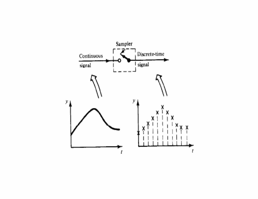
Samplers• Flow rates, pressures, liquid levels, temperatures, etc, are
provided continuously by the various sensors andtransducers.
• The computer can handle information on a discrete timebasis.
• Sampler is a switch which closes at specific time intervalswithin which the continuous signal is converted intosampled values. Each sampled value is used by the computercontrol algorithm to give output result within the specifictime interval of sampling.
• If during this period (reading value, calculating error andmaking a control action) measured value changed, it is notrecognized by the computer.
Cont.

Hold element• Most of the final control elements (pneumatic valves
particularly) are actuated by continuous time signals (e.g.,compressed air).
• The discrete time signal from computer output (computedby program) is converted into continuous signal by holdelement.
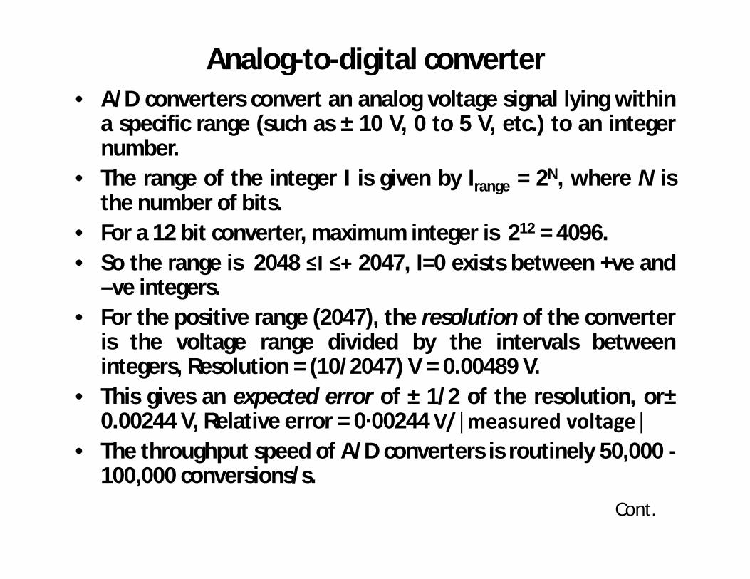
Analog-to-digital converter• A/D converters convert an analog voltage signal lying within
a specific range (such as ± 10 V, 0 to 5 V, etc.) to an integernumber.
• The range of the integer I is given by Irange = 2N, where N isthe number of bits.
• For a 12 bit converter, maximum integer is 212 = 4096.• So the range is 2048 ≤I ≤+ 2047, I=0 exists between +ve and
–ve integers.• For the positive range (2047), the resolution of the converter
is the voltage range divided by the intervals betweenintegers, Resolution = (10/2047) V = 0.00489 V.
• This gives an expected error of ± 1/2 of the resolution, or±0.00244 V, Relative error = 0·00244 V/│measured voltage│
• The throughput speed of A/D converters is routinely 50,000 -100,000 conversions/s.
Cont.

Ex: As an illustration of A/D conversion, suppose the 12-bitconverter measure voltages and reports the integer 1261and 21 as a result of the conversion. Determine the actualmeasured voltage for I=1261 and 21. Assume expected erroris ± 1/2 of the resolution.
Ans: For I=1261, Vmeasured = (10 ×1261/2047) = 6.16023 VRelative error = ± 0·00244/6.16023 = ± 0.000397 =± 0.0397%

Digital-to-analog converter• D/A converters are the reverse of A/D conversion. An integer
with range 2N is converted to an analog voltage output.• Ex: For output of 3.5 V determine the input integer for a D/A
converter.• Iinput =2047× Voutput/10 = (2047) (3.5) /10=716.45 ≈716• It is rounded to Iinput = 716. The actual output voltage of V
output = 716 X 10 /2047 = 3.49780 V≈3.5 V

Multiplexer• Multiplexers multiplex several similar measurements from a
remote location and sequentially transmit these over only afew lines.
• Consider 10 thermocouple measurements from a process,each with a voltage signal of – 10 mV. First of all, one maynot wish to run 10 lines and use 10 channels of our A/Dconverters just for these signals, so multiplexing isnecessary.
• This is an electronic switch with several ports, which canserve sequentially several lines carrying analog signals.
A/D converter with multiplexer

Digital I/O• A digital computer is digital I/O. It is used in a control system for1. Information concerning• Status of relays turning pumps, valves, lights, and other devices on
or off.• Status of multiplexers• Settings of various switches• Status of communication peripherals and various digital logic
devices2. Control commands to• Relays, switches, solenoid, digital logic devices• Stepping motors3. Communication between• Several computers• A computer and its peripherals, etc.
Cont.

• The digital signals are fully compatible with a computer.• The transmission (input/output) of digital signals by I/O
interface can either in parallel (two way, in and out,simultaneous transmission) or in series (one way, in or outtransmission).
• The transmission rates vary from very low to very high, andare expressed in terms of baud rates
• Baud rate=10 × (number of character transmitted/sec)

Computer control loops (multiple)

Modes of Computer Control
• Computer control is usually carried out in one of two modes: supervisory control or direct digital control (DDC).
It involves resetting theset-point of the localcontroller according tosome computeralgorithm.
Cont.

It requires that all the controller action be carried out by thedigital computer. Measurements are sent to the computerand compared with the set point; then the computedcontrol action is transmitted to the actuator.

Programmable logic controller (PLC)• Modern industrial control systems are microprocessor-based
programmable systems containing hardware and software.• These are direct digital control, distributed control,
programmable control, and PID action.• The processor in a PLC system has software that is easily
programmable and flexible, making the initial program,updates, modifies.
• PLC are configured to receive a certain numbers ofinputs(both analog and digital) and to control a certainnumber of outputs like actuators, displays or other types ofdevices.
• PLCs are categorized into low-end, midrange, and high- end.;Low-end is from 64 expandable up to 256 I/Os, midrange isexpandable up to 2,048 I/Os, and high-end is expandable upto 8,192 I/Os.
Cont.

• PLCs have the ability to communicate with each other on alocal area network (LAN) or a wide area network (WAN),-these send operational data to, and be controlled from, acentral computer terminal.
• The individual control loops are not independent in a processbut are interrelated.
• Measured variables may be monitored and manipulatedvariables controlled simultaneously.
• Several processors also may be connected to a mainframecomputer for complex control functions.

Block diagram of programmable controller
Block diagram processing unit

• The central processing unit can be divided into the processor, memory, and input and output units or modules.
• The units are interconnected by a two-way 16-bit data bus, a one-way address bus, and a one-way enable bus.
• The enable and address buses are controlled by the processor, which uses software instructions for its direction.
• When addressing an input module, the module is selectedwith its enable bus code.
• The address bus then can be used to select which externalinput data is to be put onto the two-way data bus.
• This data is then transferred to memory to wait for the nextstep from the software instructions.
• The output modules are addressed and selected in the sameway as the input modules. The unit is selected by the enablecode, and the address bus directs the data placed on the databus from the memory by the processor to its output.

Operation cycle in the PLC • The operation cycle of a PLC is made up of two separate modes; these are
the I/O scan mode, followed by the execution mode.• I/O scan mode is the period when the processor updates the output
control signals, based on the information received from the previous I/Oscan cycle after its evaluation of the signals. The processor then scans theinputs in a serial mode and updates its internal memory as to the status ofthe inputs.
• Execution mode follows the I/O scan mode. In this mode, the processorevaluates the input data stored in memory against the data programmedinto the CPU. The processor then can determine the actions to be taken bythe output modules, and puts the data into memory for transfer to theoutput modules during the next I/O scan mode.
• Scan time is the time required for the PLC to complete one I/O scan plusthe execution cycle. This time depends on the number of input and outputchannels, the length of the ladder instruction sets, and the speed of theprocessor. A typical scan time is between 5 and 20 ms.

Computer based digitally controlled process

• DCS was originally considered as a replacement of huge panels, located incentral control rooms and comprising 100 to 1000 process instruments.
• It has expanded information-processing role, adding advanced controlsuch as, model reference control and expert systems; information-analysistools, such as statistical process control and intelligent alarming; decisionsupport applications such as predictive maintenance and documentmanagement; and business system integration capabilities.
• The DCS has three essential qualities1. first is to distribute its functions into relatively small sets of semiautonomous
subsystems, which are interconnected via a high-speed communicationsnetwork. These functions include data collection, process control, processanalysis and supervision, storage and retrieval of archived information, andthe presentation and reporting of information. The advantages are:• lower exposure to component or subsystem failure and better isolation to
facilitate maintenance and upgrades.• better partitioning of application requirements• improved modularity for application development• geographical distribution reduces installation costs (reduced wiring) and
provides more localized operational supervision
Distributed control system (DCS)
Cont.

2. 2nd to automate the manufacturing process by integrating advanced regulatorycontrol, logic and sequential control, it also includes information such as:• activity-based cost accounting• production scheduling and dispatching• preventative or predictive maintenance scheduling• validation of employee job certification and readiness• information exchange with business, logistics, and transportation applications
3. 3rd a DCS organizes the command structure and information flow among itsconstituent parts so as to have it act as a single automation system unifying thevarious subsystems, including:• process signal input and conditioning• process actuator signal output• regulatory, combinatorial, and sequence logic and procedural and supervisory
control• human readable process displays of current values, alarms, trends, and
calculations• human actions including setpoint changes, manual overrides and alarm
handling• application subsystems such as process optimization and manufacturing
support• information-storage subsystems• communications subsystems
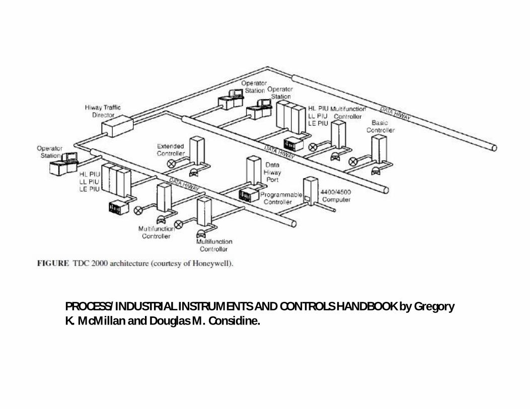
PROCESS/INDUSTRIAL INSTRUMENTS AND CONTROLS HANDBOOK by Gregory K. McMillan and Douglas M. Considine.

Figure: DCS presented by Siemens Energy & Automation, Inc.
Both DCS and PLC systems share the following components: Field devices; Input/output modules; Controllers ; Human machine interface (HMI); Engineering; Supervisory control; Business integration

Comparison between PLC and DCS by Siemens Energy & Automation, Inc.
PLC is applied DCS is applied
Factory automation - manufacturing orassembly of specific items “thing”
Process automation applications Involvesthe combination and/or transformation ofraw materials “stuff”
Product is visible as it moves through theprocess
Often impossible to visually see theproduct as it moves through the process
High-speed logic control (such as motors) Regulatory/Analog (loop) control
Simple Batch control Complex Batch Control
Value of the individual component being manufactured is relatively low
The value of a “batch” can be very high (either in raw material cost or market value)
Downtime mainly results in lost production Downtime can result in process equipmentdamage (product hardens, etc.)
Return to steady state production after anoutage is short and relativelystraightforward
Return to steady state production after an unplanned outage can be long, expensive, and difficult
Typically, the heart of the system is thecontroller
Typically, the heart of the system is the HMI

PLC is applied DCS is applied
The operator's primary role is to handleexceptions
The operator’s interaction is typicallyrequired to keep the process in its targetperformance range
Fast logic scan (approx. 10ms) is required toperform motor or motion control
Control loops require deterministic scanexecution at a speed of 100 to 500 ms
Redundancy may not be cost justified System redundancy is often required
System can be taken offline to makeconfiguration changes
Online configuration often requiredchanges
Analog Control: Simple PID only Analog Control: Simple to advanced PID control up to Advanced Process Control
Diagnostics to tell you when something isbroken
Asset Management alerts you to what might break before it does
High level programming languages areavailable for creating custom logic
Custom logic created from existing functionblocks
Solution is generic in nature, to be appliedon a wide variety of applications
Use of pre-defined, pre-tested functionssaves time

Data processing for process plants • In a process plant thousands of variables like flow rates, temperatures, pressures,
levels, compositions, etc. are routinely measured and automatically recorded forprocess control, online optimization or process economic evaluation.
• In recent days, computers and data acquisition systems collect and process largevolume of data sampled with low to moderate frequency in the order of minutesor seconds.
• Modern days computers not only access large volume of data at higher frequencybut also eliminate errors in data to increase its accuracy and validity.
• During process measurement and data transmission the data involve errors.Measurement errors are of two types, i) Random error, ii) Gross error.
• Outcome of random errors are uncertain with respect to its sign (+ve/-ve) andmagnitude. If measurement is repeated with same process condition andinstrument, dissimilar values are obtained from the measurement. The randomerrors are characterized by probability distribution function like Gaussiandistribution. The error is caused by power supply fluctuations, networktransmission and signal conversion noise, analog input filtering, changes inambient conditions, etc. The errors are beyond the control of process engineerand always present in a measured data and it is characterized by high frequencyand low magnitude unlike some occasional spike.
Cont.

• The gross error corresponds to non random events and is caused by instrumentmalfunctioning (due to improper installation of measuring devices), malcalibration, wear or corrosion of sensors, solid deposits, etc. If measurement isrepeated with same process condition and instrument, similar values of grosserrors are obtained from the measurement. Good installation and maintenanceprocedures prevent gross error to involve. Wear and fouling of sensors cause agross errors which increases slowly over long period of time and can be eliminatedby proper cleaning. The gross errors maintain a trend and are of largermagnitude than random error.
• Small error in measured signal leads to deterioration of control performance,uneconomic process and unsafe operation regimes.
• Different data processing technique have been used to eliminate errors.• Signal conditioning by analog and digital filters. These are used to reduce the
effect of high frequency noise in the measurement. Today smart sensors performsdiagnostic check about the hardware problem and acceptability of the data.
• Statistical quality control test (SQC) detects significant error in process data. It isused separately for each process variables and does not use knowledge of processmodel; hence does not ensure consistency of the data with respect tointerrelationship among process variables. Obvious gross error is eliminated andfirst step for eliminating random error.
• Data reconciliation is a technique to improve accuracy of measurement byreducing random error. It explicitly makes use of process model constrains toestimate process variables by adjusting process measurements in such a way tosatisfy the process constrains.
Cont.
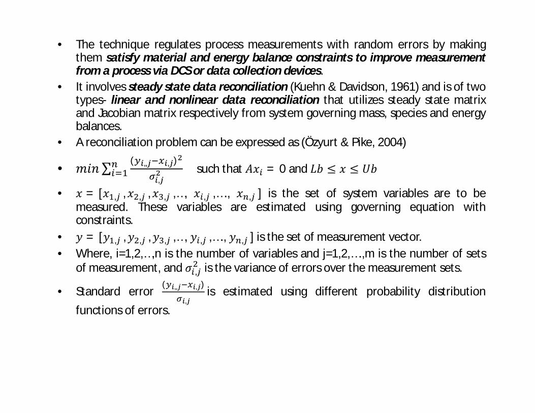
• The technique regulates process measurements with random errors by makingthem satisfy material and energy balance constraints to improve measurementfrom a process via DCS or data collection devices.
• It involves steady state data reconciliation (Kuehn & Davidson, 1961) and is of twotypes- linear and nonlinear data reconciliation that utilizes steady state matrixand Jacobian matrix respectively from system governing mass, species and energybalances.
• A reconciliation problem can be expressed as (Özyurt & Pike, 2004)
• 푚푖푛∑ ( ,, , )
,such that 퐴푥 = 0 and 퐿푏 ≤ 푥 ≤ 푈푏
• 푥 = [푥 , , 푥 , , 푥 , ,…, 푥 , ,…., 푥 , ] is the set of system variables are to bemeasured. These variables are estimated using governing equation withconstraints.
• 푦 = [푦 , , 푦 , , 푦 , ,…, 푦 , ,…., 푦 , ] is the set of measurement vector.• Where, i=1,2,…,n is the number of variables and j=1,2,….,m is the number of sets
of measurement, and 휎 , is the variance of errors over the measurement sets.
• Standard error( ,, , )
,is estimated using different probability distribution
functions of errors.

Fig: Typical arrangement between the DCS and the Data Reconciliation,Simulation, and Optimization procedures (from Simulation Sciences, Inc.,1989) presented by Romagnoli & Sanchez, DATA PROCESSING ANDRECONCILIATION FOR CH EM ICAL PROCESS OPERATIONS

• The 23-cm-diameter distillation column under study is used to separate ethanol and water. Itcontains 12 sieve trays with a 30-cm spacing (Fig.) as well as three possible feed locations, anexternal reboiler, and two condensers, which are used at the bottom and the top of the column.The second condenser is also used as a reflux drum; a pump sends the reflux back to thecolumn (tray 1) and the product to the product tank. Presented by Romagnoli & Sanchez, DATAPROCESSING AND RECONCILIATION FOR CH EM ICAL PROCESS OPERATIONS.
The following variables are monitored through the DCS:• Temperatures at trays 12, 11, 9,
7, 5, 3, 1• Temperatures of feed, distillate,
bottoms, and water in and out of the condenser.
• Flowrates of steam to thereboiler, water to the condenser,feed, distillate, bottoms, andreflux
• Pressure at the bottom of thecolumn
• Liquid levels in the condenserand the bottom of the column
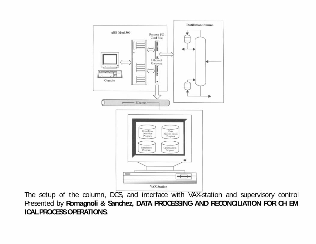
The setup of the column, DCS, and interface with VAX-station and supervisory controlPresented by Romagnoli & Sanchez, DATA PROCESSING AND RECONCILIATION FOR CH EMICAL PROCESS OPERATIONS.
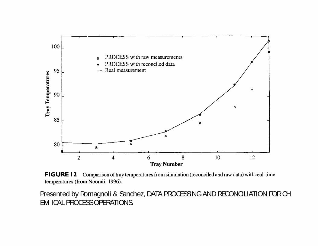
Presented by Romagnoli & Sanchez, DATA PROCESSING AND RECONCILIATION FOR CH EM ICAL PROCESS OPERATIONS.

Presented by Romagnoli & Sanchez, DATA PROCESSING AND RECONCILIATION FOR CHEMICAL PROCESS OPERATIONS.

Reference• Stephanopoulos, G., "Chemical Process Control and Introduction to theory
and practice", Prentice Hall.• William C. Dunn, Introduction to Instrumentation, Sensors, and Process
Control, ARTECH HOUSE, Norwood, MA, 2006.

Thank You