concept channel design & channel development …...concept channel design & channel...
TRANSCRIPT
Concept Channel Design & Channel Development Strategy D R A F T
Concept Channel Design & Channel Development Strategy D R A F T
Document Ref: AGH-CEP0-EG-REP-0012
In May 2016 the Special Minister of State asked Infrastructure Victoria to provide advice on the future capacity of Victoria’s commercial ports. Specifically, the Minister has asked for advice on when the need for a second container port is likely to arise and which variables may alter this timeline. The Minister has also asked for advice on where a second container port would ideally be located and under what conditions, including the suitability of, and barriers to investing in, sites at the Port of Hastings and the Bay West location.
In undertaking this task, Infrastructure Victoria reviewed work that was completed as part of the Port of Hastings development project before it was cancelled in 2014. This document forms part of the initial work undertaken for the proposed port development at Hastings. Infrastructure Victoria considers that much of the previous Hastings work, although preliminary in nature, is relevant and suitable for informing a strategic assessment. Therefore, Infrastructure Victoria has requested that preliminary and draft reports previously commissioned for the development project be reissued to form part of the evidence base on which Infrastructure Victoria will use in providing the Minister with advice.
The opinions, conclusions and any recommendations in this document are based on conditions encountered and information reviewed at the date of preparation of the document and for the purposes of the Port of Hastings Development Project.
Infrastructure Victoria and its consultants have used the information contained in these reports as an input but have not wholly relied on all the information presented in these reports.
D R A F T
Port of Hastings Development Project – Design and Engineering Concept Channel Design & Channel Development Strategy D R A F T
28-Feb-17
Port of Hastings Development Project – Design and Engineering
Concept Channel Design & Channel Development Strategy
D R A F T
Client: Infrastructure Victoria
ABN: 44 128 890 975
Prepared by the AECOM + GHD Joint Venture
AECOM Australia Pty Ltd Level 9, 8 Exhibition Street, Melbourne VIC 3000, Australia T +61 3 9653 1234 F +61 3 9654 7117 www.aecom.com
+
GHD Pty Ltd Level 8, 180 Lonsdale Street, Melbourne VIC 3000, Australia T +61 3 8687 8000 F +61 3 8687 8111 www.ghd.com
JV ABN: 57 194 323 595
The AECOM + GHD Joint Venture in Australia and New Zealand are certified to the latest version of ISO9001, ISO14001, AS/NZS4801 and OHSAS18001.
© AECOM + GHD Joint Venture. All rights reserved.
This Report has been prepared by the AECOM + GHD Joint Venture for the Port of Hastings Development Authority and may only be used and relied on by the Port of Hastings Development Authority for the purpose agreed between the AECOM + GHD Joint Venture and the Port of Hastings Development Authority as set out in this Report.
The AECOM + GHD Joint Venture otherwise disclaims responsibility to any person other than the Port of Hastings Development Authority arising in connection with this Report. The AECOM + GHD Joint Venture also excludes implied warranties and conditions, to the extent legally permissible.
The services undertaken by the AECOM + GHD Joint Venture in connection with preparing this Report were limited to those specifically detailed in the Report and are subject to the scope limitations set out in the Report.
The opinions, conclusions and any recommendations in this Report are based on conditions encountered and information reviewed at the date of preparation of the Report. The AECOM + GHD Joint Venture has no responsibility or obligation to update this Report to account for events or changes occurring subsequent to the date that the Report was prepared.
The opinions, conclusions and any recommendations in this Report are based on assumptions made by the AECOM + GHD Joint Venture described in this Report. The AECOM + GHD Joint Venture disclaims liability arising from any of the assumptions being incorrect.
D R A F T
Port of Hastings Development Project – Design and Engineering Concept Channel Design & Channel Development Strategy D R A F T
28-Feb-17
Quality Information
Project Port of Hastings Development Project – Design and Engineering
Document Concept Channel Design & Channel Development Strategy D R A F T
Ref AGH-CEP0-EG-REP-0012
Date 28-Feb-17
Prepared by B. Gray
Reviewed by A. Kennedy & R. Clarke
Revision History
Revision Revision Date
Details Authorised
Name/Position Signature
A 3-Nov-14 Draft for Discussion Richard Clarke Port Planning Workstream Manager
* Richard Clarke
B 7-Nov-14 Draft with channel plans Richard Clarke Port Planning Workstream Manager
* Richard Clarke
0 13-Mar-15 Final Working Draft Richard Clarke Port Planning Workstream Manager
* Richard Clarke
1 28-Feb-17 Final Working Draft – Infrastructure Victoria Release
Austin Kennedy * Austin Kennedy
D R A F T
Port of Hastings Development Project – Design and Engineering Concept Channel Design & Channel Development Strategy D R A F T
28-Feb-17
Table of Contents
1.0 Introduction 1 2.0 Objectives 1 3.0 PIANC Design Methodology 1 4.0 Initial Concept Design to PIANC 1
4.1 Design Vessels 1 4.2 Channel Widths 2 4.3 Channel Depths 5 4.4 Concept Plans and Dredge Volumes 7
5.0 Optimisation Opportunities and Costs 8 6.0 Optimisation Methods and Tools 9
6.1 Underkeel Clearance Analysis 9 6.2 Real Time Simulations 9 6.3 Discrete Event Simulation 9
6.3.1 Model Development 9 6.3.2 Outputs 10 6.3.3 Scenarios 11
7.0 Channel Optimisation Work Plan 13
Concept Channel Plans 14 Appendix A
Concept Channel Design 15 Appendix BChannel Arrangement 15 Channel Width Factors 16
Inner/Outer Channel 16 Basic Manoeuvring Lane 17 Vessel Speed 17 Prevailing Cross Wind 17 Prevailing Cross Current 18 Prevailing Longitudinal Current 18 Beam and Stern Quartering Wave Height 19 Aids to Navigation 19 Depth of Waterway 19 Width for Bank Clearance 19 Traffic Density 19
D R A F T
Port of Hastings Development Project – Design and Engineering Concept Channel Design & Channel Development Strategy D R A F T
28-Feb-17 1
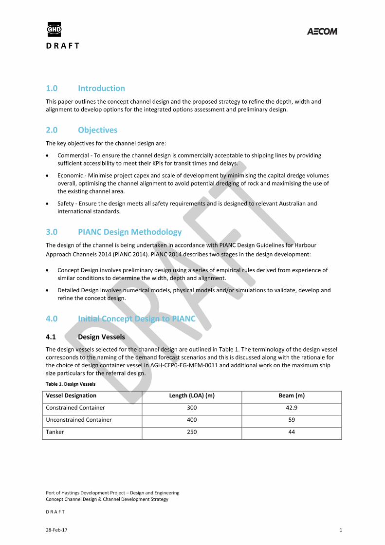
1.0 Introduction
This paper outlines the concept channel design and the proposed strategy to refine the depth, width and alignment to develop options for the integrated options assessment and preliminary design.
2.0 Objectives
The key objectives for the channel design are:
Commercial - To ensure the channel design is commercially acceptable to shipping lines by providing sufficient accessibility to meet their KPIs for transit times and delays.
Economic - Minimise project capex and scale of development by minimising the capital dredge volumes overall, optimising the channel alignment to avoid potential dredging of rock and maximising the use of the existing channel area.
Safety - Ensure the design meets all safety requirements and is designed to relevant Australian and international standards.
3.0 PIANC Design Methodology
The design of the channel is being undertaken in accordance with PIANC Design Guidelines for Harbour
Approach Channels 2014 (PIANC 2014). PIANC 2014 describes two stages in the design development:
Concept Design involves preliminary design using a series of empirical rules derived from experience of similar conditions to determine the width, depth and alignment.
Detailed Design involves numerical models, physical models and/or simulations to validate, develop and refine the concept design.
4.0 Initial Concept Design to PIANC
4.1 Design Vessels
The design vessels selected for the channel design are outlined in Table 1. The terminology of the design vessel corresponds to the naming of the demand forecast scenarios and this is discussed along with the rationale for the choice of design container vessel in AGH-CEP0-EG-MEM-0011 and additional work on the maximum ship size particulars for the referral design.
Table 1. Design Vessels
Vessel Designation Length (LOA) (m) Beam (m)
Constrained Container 300 42.9
Unconstrained Container 400 59
Tanker 250 44
D R A F T
Port of Hastings Development Project – Design and Engineering Concept Channel Design & Channel Development Strategy D R A F T
28-Feb-17 2
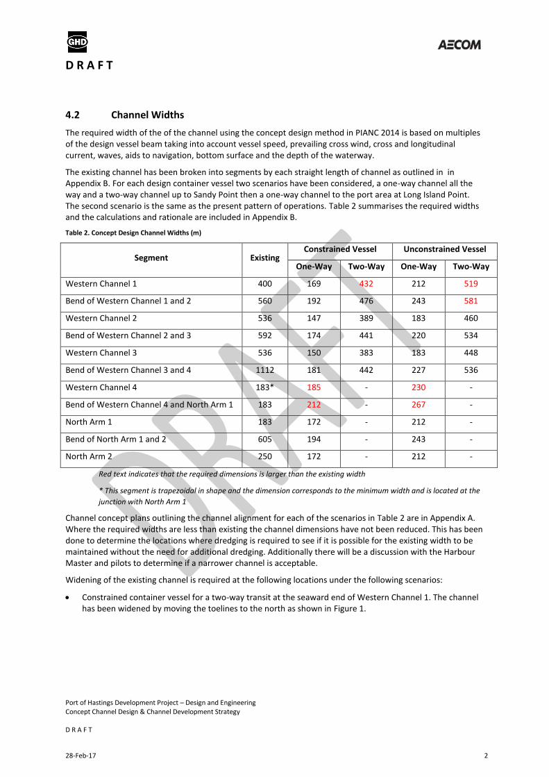
4.2 Channel Widths
The required width of the of the channel using the concept design method in PIANC 2014 is based on multiples of the design vessel beam taking into account vessel speed, prevailing cross wind, cross and longitudinal current, waves, aids to navigation, bottom surface and the depth of the waterway.
The existing channel has been broken into segments by each straight length of channel as outlined in in Appendix B. For each design container vessel two scenarios have been considered, a one-way channel all the way and a two-way channel up to Sandy Point then a one-way channel to the port area at Long Island Point. The second scenario is the same as the present pattern of operations. Table 2 summarises the required widths and the calculations and rationale are included in Appendix B.
Table 2. Concept Design Channel Widths (m)
Segment Existing Constrained Vessel Unconstrained Vessel
One-Way Two-Way One-Way Two-Way
Western Channel 1 400 169 432 212 519
Bend of Western Channel 1 and 2 560 192 476 243 581
Western Channel 2 536 147 389 183 460
Bend of Western Channel 2 and 3 592 174 441 220 534
Western Channel 3 536 150 383 183 448
Bend of Western Channel 3 and 4 1112 181 442 227 536
Western Channel 4 183* 185 - 230 -
Bend of Western Channel 4 and North Arm 1 183 212 - 267 -
North Arm 1 183 172 - 212 -
Bend of North Arm 1 and 2 605 194 - 243 -
North Arm 2 250 172 - 212 -
Red text indicates that the required dimensions is larger than the existing width
* This segment is trapezoidal in shape and the dimension corresponds to the minimum width and is located at the
junction with North Arm 1
Channel concept plans outlining the channel alignment for each of the scenarios in Table 2 are in Appendix A. Where the required widths are less than existing the channel dimensions have not been reduced. This has been done to determine the locations where dredging is required to see if it is possible for the existing width to be maintained without the need for additional dredging. Additionally there will be a discussion with the Harbour Master and pilots to determine if a narrower channel is acceptable.
Widening of the existing channel is required at the following locations under the following scenarios:
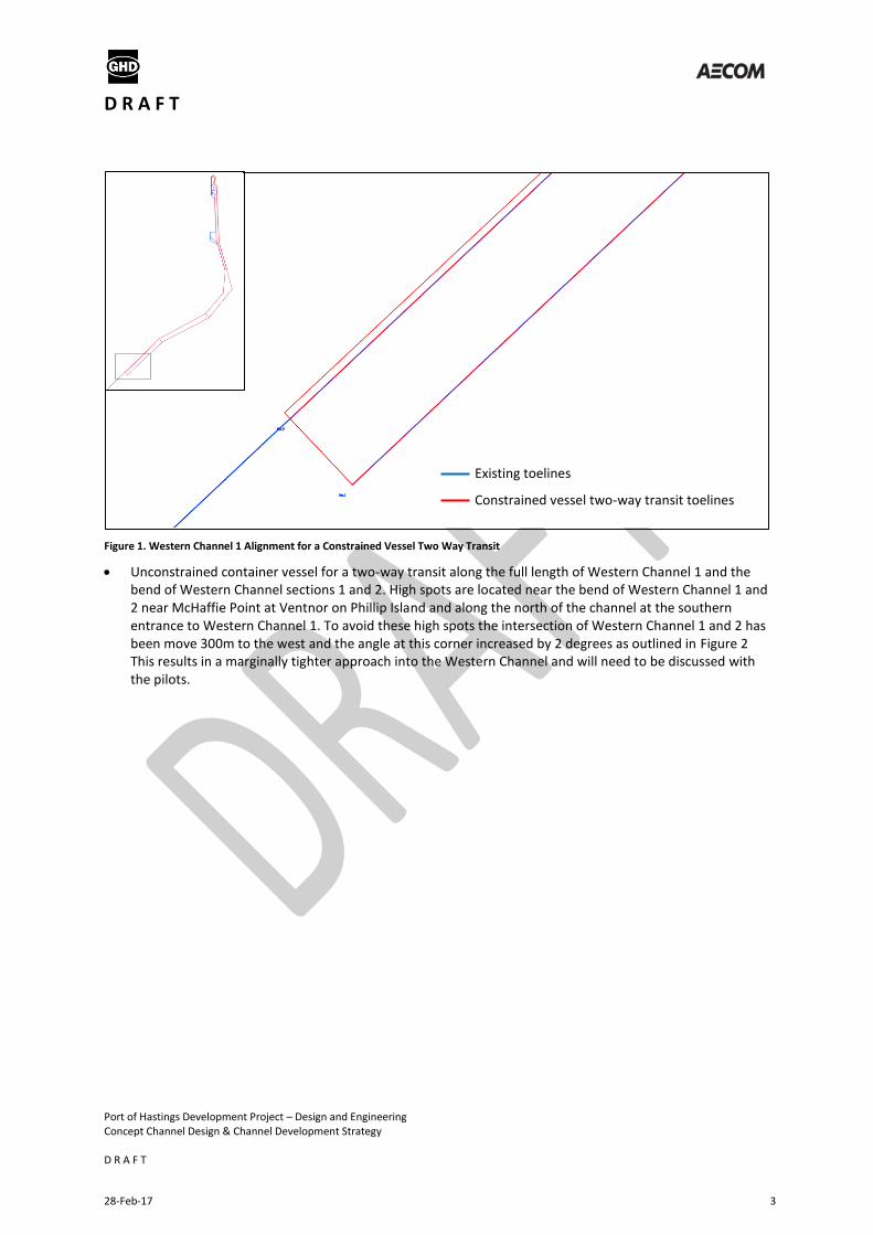
Constrained container vessel for a two-way transit at the seaward end of Western Channel 1. The channel has been widened by moving the toelines to the north as shown in Figure 1.
D R A F T
Port of Hastings Development Project – Design and Engineering Concept Channel Design & Channel Development Strategy D R A F T
28-Feb-17 3
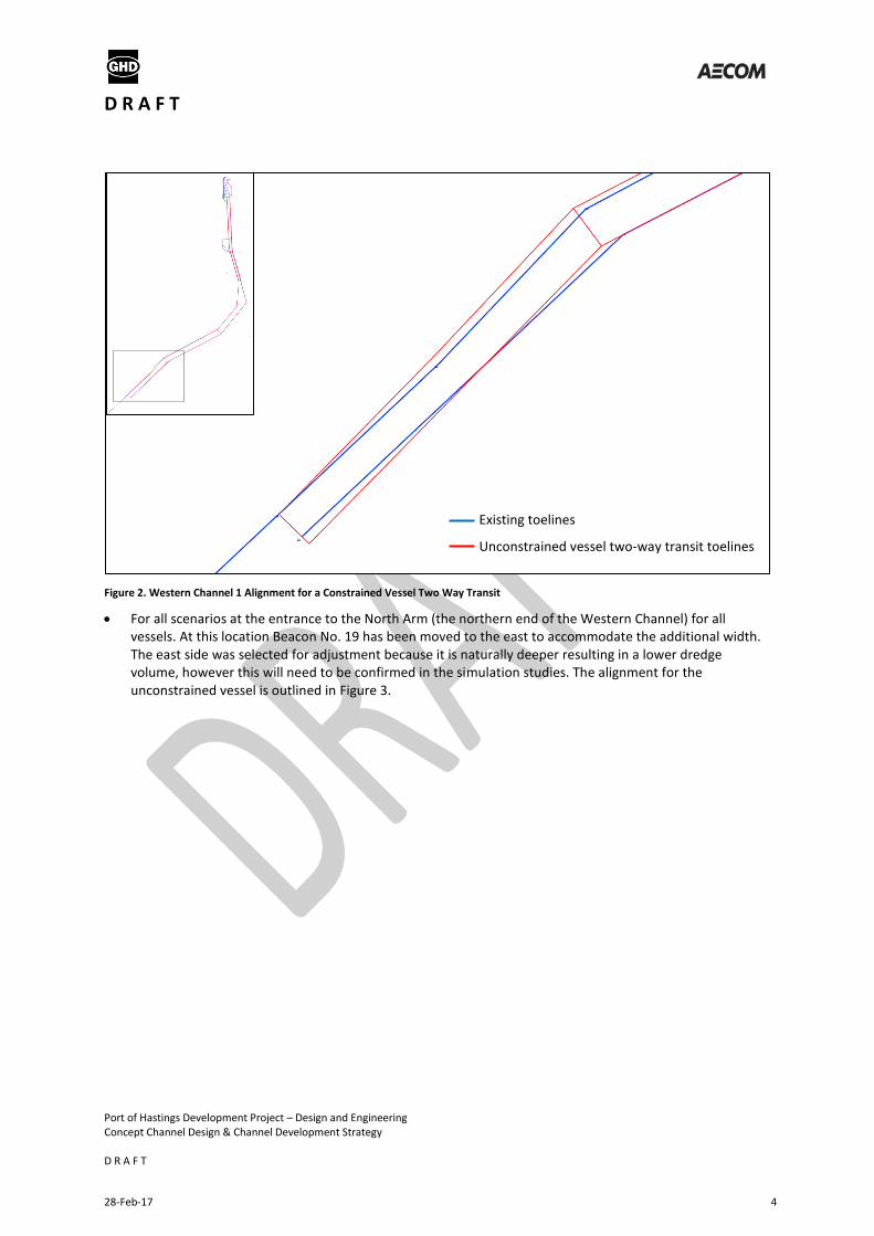
Figure 1. Western Channel 1 Alignment for a Constrained Vessel Two Way Transit
Unconstrained container vessel for a two-way transit along the full length of Western Channel 1 and the bend of Western Channel sections 1 and 2. High spots are located near the bend of Western Channel 1 and 2 near McHaffie Point at Ventnor on Phillip Island and along the north of the channel at the southern entrance to Western Channel 1. To avoid these high spots the intersection of Western Channel 1 and 2 has been move 300m to the west and the angle at this corner increased by 2 degrees as outlined in Figure 2 This results in a marginally tighter approach into the Western Channel and will need to be discussed with the pilots.
Existing toelines
Constrained vessel two-way transit toelines
D R A F T
Port of Hastings Development Project – Design and Engineering Concept Channel Design & Channel Development Strategy D R A F T
28-Feb-17 4
Figure 2. Western Channel 1 Alignment for a Constrained Vessel Two Way Transit
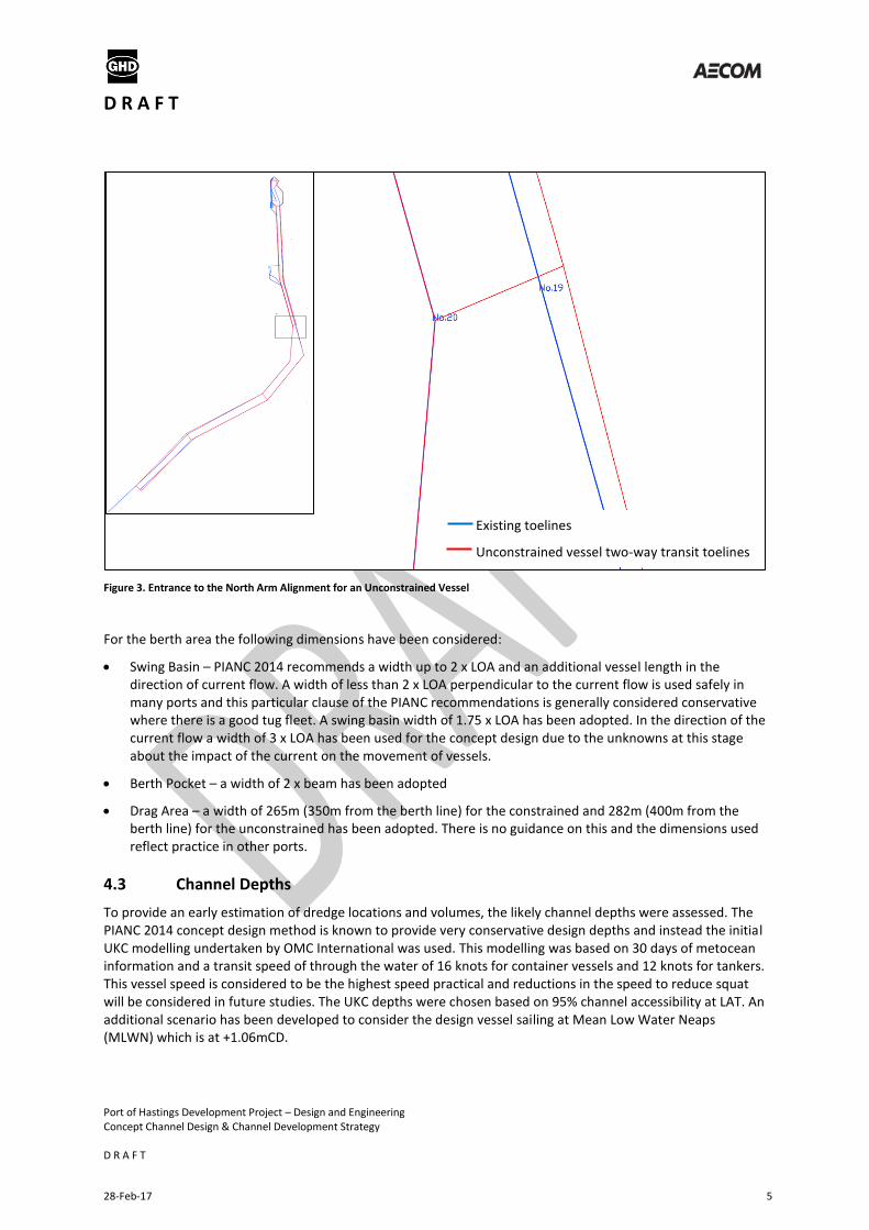
For all scenarios at the entrance to the North Arm (the northern end of the Western Channel) for all vessels. At this location Beacon No. 19 has been moved to the east to accommodate the additional width. The east side was selected for adjustment because it is naturally deeper resulting in a lower dredge volume, however this will need to be confirmed in the simulation studies. The alignment for the unconstrained vessel is outlined in Figure 3.
Existing toelines
Unconstrained vessel two-way transit toelines
D R A F T
Port of Hastings Development Project – Design and Engineering Concept Channel Design & Channel Development Strategy D R A F T
28-Feb-17 5
Figure 3. Entrance to the North Arm Alignment for an Unconstrained Vessel
For the berth area the following dimensions have been considered:
Swing Basin – PIANC 2014 recommends a width up to 2 x LOA and an additional vessel length in the direction of current flow. A width of less than 2 x LOA perpendicular to the current flow is used safely in many ports and this particular clause of the PIANC recommendations is generally considered conservative where there is a good tug fleet. A swing basin width of 1.75 x LOA has been adopted. In the direction of the current flow a width of 3 x LOA has been used for the concept design due to the unknowns at this stage about the impact of the current on the movement of vessels.
Berth Pocket – a width of 2 x beam has been adopted
Drag Area – a width of 265m (350m from the berth line) for the constrained and 282m (400m from the berth line) for the unconstrained has been adopted. There is no guidance on this and the dimensions used reflect practice in other ports.
4.3 Channel Depths
To provide an early estimation of dredge locations and volumes, the likely channel depths were assessed. The PIANC 2014 concept design method is known to provide very conservative design depths and instead the initial UKC modelling undertaken by OMC International was used. This modelling was based on 30 days of metocean information and a transit speed of through the water of 16 knots for container vessels and 12 knots for tankers. This vessel speed is considered to be the highest speed practical and reductions in the speed to reduce squat will be considered in future studies. The UKC depths were chosen based on 95% channel accessibility at LAT. An additional scenario has been developed to consider the design vessel sailing at Mean Low Water Neaps (MLWN) which is at +1.06mCD.
Existing toelines
Unconstrained vessel two-way transit toelines
D R A F T
Port of Hastings Development Project – Design and Engineering Concept Channel Design & Channel Development Strategy D R A F T
28-Feb-17 6
A survey tolerance of 0.25m is assumed as well as the following over-dredge allowances:
Vertical – 0.5 m
Horizontal – 3.0 m through the toeline where appropriate
Batters are assumed to be 1 in 3 generally and 1 in 5 for the north edge of the port area. No allowances have been made for siltation in the channel based on preliminary advice from the Hydrodynamics workstream. A 0.3m siltation allowance was included for the port area.
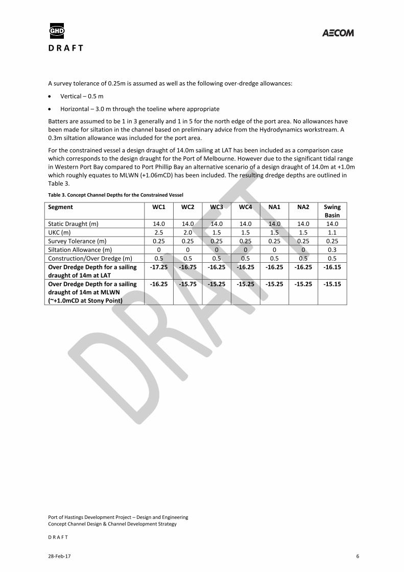
For the constrained vessel a design draught of 14.0m sailing at LAT has been included as a comparison case which corresponds to the design draught for the Port of Melbourne. However due to the significant tidal range in Western Port Bay compared to Port Phillip Bay an alternative scenario of a design draught of 14.0m at +1.0m which roughly equates to MLWN (+1.06mCD) has been included. The resulting dredge depths are outlined in Table 3.
Table 3. Concept Channel Depths for the Constrained Vessel
Segment WC1 WC2 WC3 WC4 NA1 NA2 Swing Basin
Static Draught (m) 14.0 14.0 14.0 14.0 14.0 14.0 14.0
UKC (m) 2.5 2.0 1.5 1.5 1.5 1.5 1.1
Survey Tolerance (m) 0.25 0.25 0.25 0.25 0.25 0.25 0.25
Siltation Allowance (m) 0 0 0 0 0 0 0.3
Construction/Over Dredge (m) 0.5 0.5 0.5 0.5 0.5 0.5 0.5
Over Dredge Depth for a sailing draught of 14m at LAT
-17.25 -16.75 -16.25 -16.25 -16.25 -16.25 -16.15
Over Dredge Depth for a sailing draught of 14m at MLWN (~+1.0mCD at Stony Point)
-16.25 -15.75 -15.25 -15.25 -15.25 -15.25 -15.15
D R A F T
Port of Hastings Development Project – Design and Engineering Concept Channel Design & Channel Development Strategy D R A F T
28-Feb-17 7
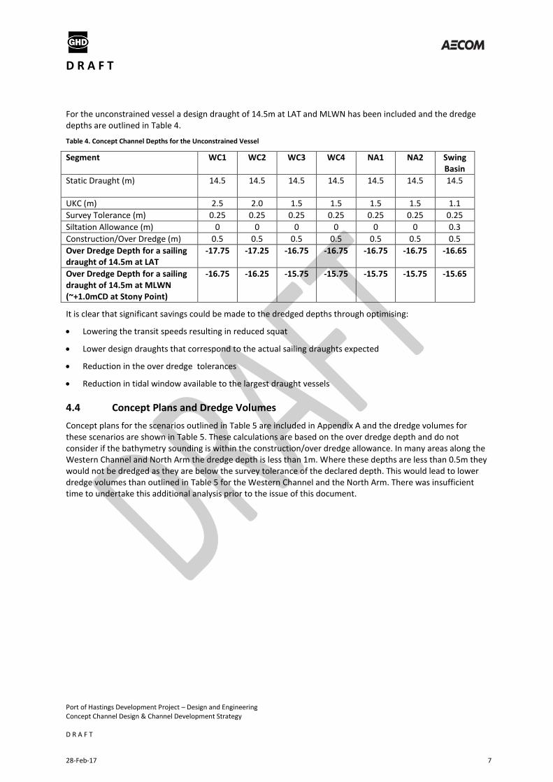
For the unconstrained vessel a design draught of 14.5m at LAT and MLWN has been included and the dredge depths are outlined in Table 4.
Table 4. Concept Channel Depths for the Unconstrained Vessel
Segment WC1 WC2 WC3 WC4 NA1 NA2 Swing Basin
Static Draught (m) 14.5 14.5 14.5 14.5 14.5 14.5 14.5
UKC (m) 2.5 2.0 1.5 1.5 1.5 1.5 1.1
Survey Tolerance (m) 0.25 0.25 0.25 0.25 0.25 0.25 0.25
Siltation Allowance (m) 0 0 0 0 0 0 0.3
Construction/Over Dredge (m) 0.5 0.5 0.5 0.5 0.5 0.5 0.5
Over Dredge Depth for a sailing draught of 14.5m at LAT
-17.75 -17.25 -16.75 -16.75 -16.75 -16.75 -16.65
Over Dredge Depth for a sailing draught of 14.5m at MLWN (~+1.0mCD at Stony Point)
-16.75 -16.25 -15.75 -15.75 -15.75 -15.75 -15.65
It is clear that significant savings could be made to the dredged depths through optimising:
Lowering the transit speeds resulting in reduced squat
Lower design draughts that correspond to the actual sailing draughts expected
Reduction in the over dredge tolerances
Reduction in tidal window available to the largest draught vessels
4.4 Concept Plans and Dredge Volumes
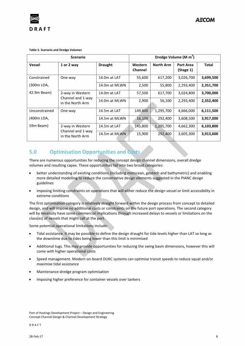
Concept plans for the scenarios outlined in Table 5 are included in Appendix A and the dredge volumes for these scenarios are shown in Table 5. These calculations are based on the over dredge depth and do not consider if the bathymetry sounding is within the construction/over dredge allowance. In many areas along the Western Channel and North Arm the dredge depth is less than 1m. Where these depths are less than 0.5m they would not be dredged as they are below the survey tolerance of the declared depth. This would lead to lower dredge volumes than outlined in Table 5 for the Western Channel and the North Arm. There was insufficient time to undertake this additional analysis prior to the issue of this document.
D R A F T
Port of Hastings Development Project – Design and Engineering Concept Channel Design & Channel Development Strategy D R A F T
28-Feb-17 8
Table 5. Scenario and Dredge Volumes
Scenario Dredge Volume (M m3)
Vessel 1 or 2 way Draught Western Channel
North Arm Port Area (Stage 1)
Total
Constrained
(300m LOA,
42.9m Beam)
One-way 14.0m at LAT 55,600 617,200 3,026,700 3,699,500
14.0m at MLWN 2,500 55,800 2,293,400 2,351,700
2-way in Western Channel and 1-way in the North Arm
14.0m at LAT 57,500 617,700 3,024,800 3,700,000
14.0m at MLWN 2,900 56,100 2,293,400 2,352,400
Unconstrained
(400m LOA,
59m Beam)
One-way 14.5m at LAT 149,800 1,295,700 4,666,000 6,111,500
14.5m at MLWN 16,100 292,400 3,608,500 3,917,000
2-way in Western Channel and 1-way in the North Arm
14.5m at LAT 145,800 1,295,700 4,662,300 6,103,800
14.5m at MLWN 15,900 292,400 3,605,300 3,913,600
5.0 Optimisation Opportunities and Costs
There are numerous opportunities for reducing the concept design channel dimensions, overall dredge volumes and resulting capex. These opportunities fall into two broad categories:
better understanding of existing conditions (including metocean, geotech and bathymetric) and enabling more detailed modelling to reduce the conservative design elements suggested in the PIANC design guidelines
imposing limiting constraints on operations that will either reduce the design vessel or limit accessibility in extreme conditions
The first optimisation category is relatively straight forward within the design process from concept to detailed design, and will impose no additional costs or constraints on the future port operations. The second category will by necessity have some commercial implications through increased delays to vessels or limitations on the class(es) of vessels that might call at the port.
Some potential operational limitations include:
Tidal assistance. It may be possible to define the design draught for tide levels higher than LAT so long as the downtime due to tides being lower than this limit is minimised
Additional tugs. This may provide opportunities for reducing the swing basin dimensions, however this will come with higher operational costs
Speed management. Modern on-board DUKC systems can optimise transit speeds to reduce squat and/or maximise tidal assistance
Maintenance dredge program optimisation
Imposing higher preference for container vessels over tankers
D R A F T
Port of Hastings Development Project – Design and Engineering Concept Channel Design & Channel Development Strategy D R A F T
28-Feb-17 9
6.0 Optimisation Methods and Tools
6.1 Underkeel Clearance Analysis
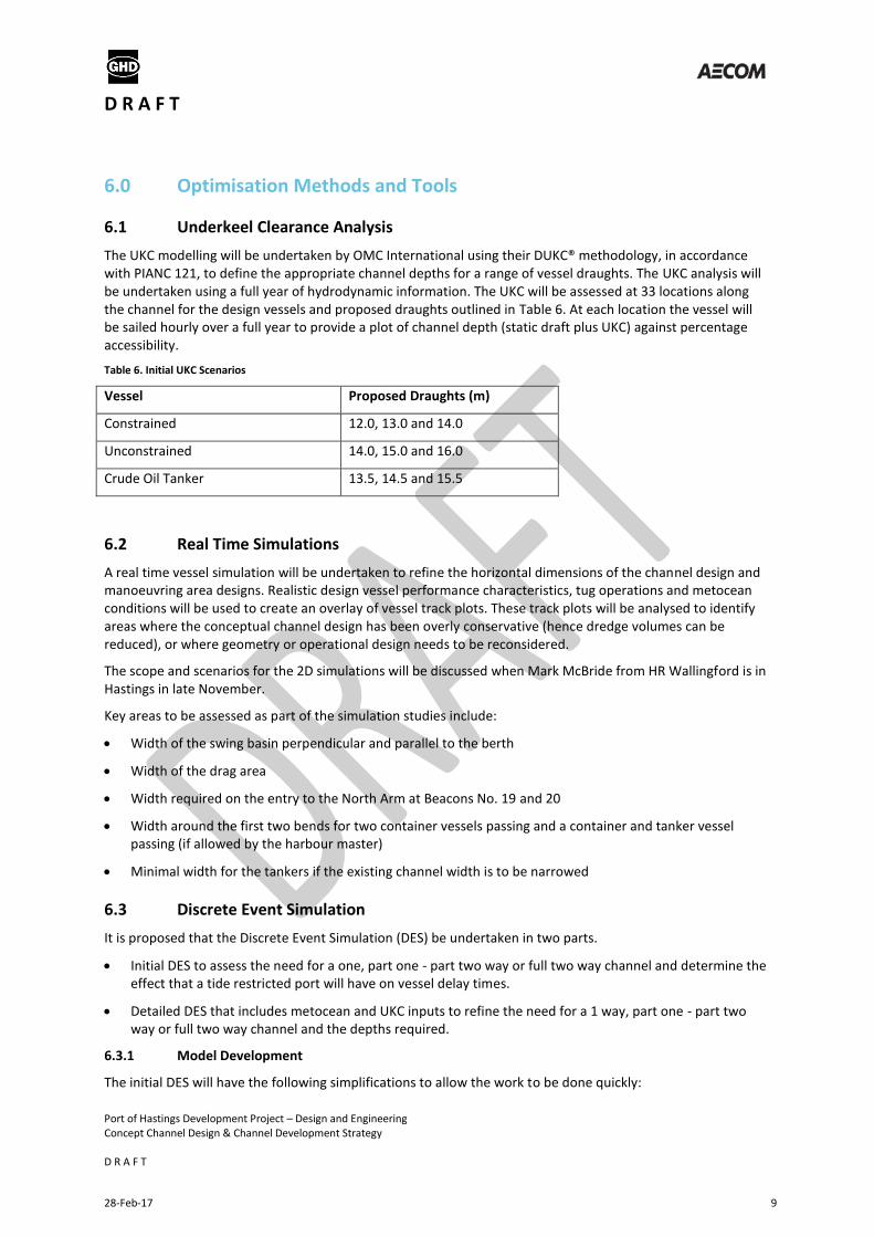
The UKC modelling will be undertaken by OMC International using their DUKC® methodology, in accordance with PIANC 121, to define the appropriate channel depths for a range of vessel draughts. The UKC analysis will be undertaken using a full year of hydrodynamic information. The UKC will be assessed at 33 locations along the channel for the design vessels and proposed draughts outlined in Table 6. At each location the vessel will be sailed hourly over a full year to provide a plot of channel depth (static draft plus UKC) against percentage accessibility.
Table 6. Initial UKC Scenarios
Vessel Proposed Draughts (m)
Constrained 12.0, 13.0 and 14.0
Unconstrained 14.0, 15.0 and 16.0
Crude Oil Tanker 13.5, 14.5 and 15.5
6.2 Real Time Simulations
A real time vessel simulation will be undertaken to refine the horizontal dimensions of the channel design and manoeuvring area designs. Realistic design vessel performance characteristics, tug operations and metocean conditions will be used to create an overlay of vessel track plots. These track plots will be analysed to identify areas where the conceptual channel design has been overly conservative (hence dredge volumes can be reduced), or where geometry or operational design needs to be reconsidered.
The scope and scenarios for the 2D simulations will be discussed when Mark McBride from HR Wallingford is in Hastings in late November.
Key areas to be assessed as part of the simulation studies include:
Width of the swing basin perpendicular and parallel to the berth
Width of the drag area
Width required on the entry to the North Arm at Beacons No. 19 and 20
Width around the first two bends for two container vessels passing and a container and tanker vessel passing (if allowed by the harbour master)
Minimal width for the tankers if the existing channel width is to be narrowed
6.3 Discrete Event Simulation
It is proposed that the Discrete Event Simulation (DES) be undertaken in two parts.
Initial DES to assess the need for a one, part one - part two way or full two way channel and determine the effect that a tide restricted port will have on vessel delay times.
Detailed DES that includes metocean and UKC inputs to refine the need for a 1 way, part one - part two way or full two way channel and the depths required.
6.3.1 Model Development
The initial DES will have the following simplifications to allow the work to be done quickly:
D R A F T
Port of Hastings Development Project – Design and Engineering Concept Channel Design & Channel Development Strategy D R A F T
28-Feb-17 10
Fixed time at berth based on the vessel size
No consideration of tug, pilot or line boat availability
Berth allocation will be based on LOA and up to 80% of the total berth length being occupied
No anchorage or tankers
Percentage allowance for downtime due to metocean conditions
Limited number of snapshots throughout the demand forecast period
Two vessel spectra corresponding to the constrained and unconstrained cases
The tidal cycle will be included to assess the effect on vessel delays from restricting access at the bottom of the tidal range. With a tidal range of about 2.5m at Stony Point there is the potential for significant savings in depth by limiting access at the bottom of the tidal range. However this needs to be balanced with the commercial need to limit the delays to container vessels.
The initial DES will assist in narrowing the scope for the 2D simulations by defining which of the one way, part one - part two way or full two way channel patterns are mostly likely for the constrained and unconstrained scenarios.
The detailed DES will be a more sophisticated model that will remove the limitations of the initial DES by including:
rules for berth allocation,
metocean conditions and UKC requirements,
tankers and the anchorage,
Bass Strait vessels along with a potential by-pass channel in the north arm, if required,
Tugs, pilots and line boats to assess the number required.
The models will be developed to generate ships calls from the time they depart the preceding port. This will allow for slow steaming into the Port of Hastings and delays prior to arrival at the Port to be measured separately.
6.3.2 Outputs
The acceptability of the channel design will be determined by safety considerations and the average and maximum delays to ships.
The key performance indicators for the port will be developed by the Commercial & Economic workstream and may include the following:
Maximum allowable waiting time to service time ratio
Maximum allowable single delay (excluding severe weather events)
Maximum average delay
Delays will be summarised by:
Berth occupancy delay due to no available berths
Channel delay due to extreme weather or poor visibility ( includes the pilot not being able to board the vessel)
Channel UKC delay due to insufficient UKC in the channel
Channel occupancy delay due to congestion in the channel
D R A F T
Port of Hastings Development Project – Design and Engineering Concept Channel Design & Channel Development Strategy D R A F T
28-Feb-17 11
6.3.3 Scenarios
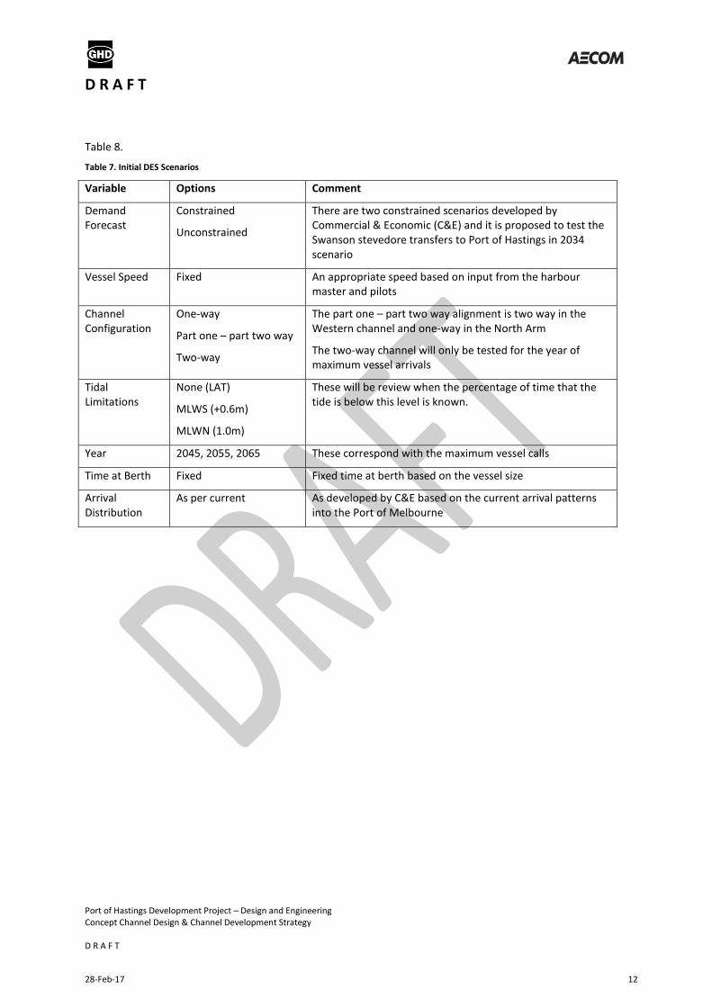
Scenarios that are proposed to be tested in the initial DES are outlined in Table 7. The detailed DES will be
undertaken in two parts with a workshop after the initial scenarios have been run to review the results and
agree on any additional scenarios to be tested. Scenarios that are proposed to be tested in the detailed DES are
outlined in
D R A F T
Port of Hastings Development Project – Design and Engineering Concept Channel Design & Channel Development Strategy D R A F T
28-Feb-17 12
Table 8.
Table 7. Initial DES Scenarios
Variable Options Comment
Demand Forecast
Constrained
Unconstrained
There are two constrained scenarios developed by Commercial & Economic (C&E) and it is proposed to test the Swanson stevedore transfers to Port of Hastings in 2034 scenario
Vessel Speed Fixed An appropriate speed based on input from the harbour master and pilots
Channel Configuration
One-way
Part one – part two way
Two-way
The part one – part two way alignment is two way in the Western channel and one-way in the North Arm
The two-way channel will only be tested for the year of maximum vessel arrivals
Tidal Limitations
None (LAT)
MLWS (+0.6m)
MLWN (1.0m)
These will be review when the percentage of time that the tide is below this level is known.
Year 2045, 2055, 2065 These correspond with the maximum vessel calls
Time at Berth Fixed Fixed time at berth based on the vessel size
Arrival Distribution
As per current As developed by C&E based on the current arrival patterns into the Port of Melbourne
D R A F T
Port of Hastings Development Project – Design and Engineering Concept Channel Design & Channel Development Strategy D R A F T
28-Feb-17 13
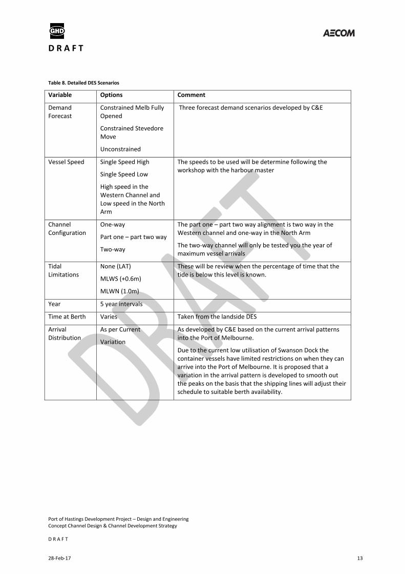
Table 8. Detailed DES Scenarios
Variable Options Comment
Demand Forecast
Constrained Melb Fully Opened
Constrained Stevedore Move
Unconstrained
Three forecast demand scenarios developed by C&E
Vessel Speed Single Speed High
Single Speed Low
High speed in the Western Channel and Low speed in the North Arm
The speeds to be used will be determine following the workshop with the harbour master
Channel Configuration
One-way
Part one – part two way
Two-way
The part one – part two way alignment is two way in the Western channel and one-way in the North Arm
The two-way channel will only be tested you the year of maximum vessel arrivals
Tidal Limitations
None (LAT)
MLWS (+0.6m)
MLWN (1.0m)
These will be review when the percentage of time that the tide is below this level is known.
Year 5 year intervals
Time at Berth Varies Taken from the landside DES
Arrival Distribution
As per Current
Variation
As developed by C&E based on the current arrival patterns into the Port of Melbourne.
Due to the current low utilisation of Swanson Dock the container vessels have limited restrictions on when they can arrive into the Port of Melbourne. It is proposed that a variation in the arrival pattern is developed to smooth out the peaks on the basis that the shipping lines will adjust their schedule to suitable berth availability.
D R A F T
Port of Hastings Development Project – Design and Engineering Concept Channel Design & Channel Development Strategy D R A F T
28-Feb-17 14
7.0 Channel Optimisation Work Plan
Below is a summary of the work plan for the channel design for navigation.
Stage 1 is currently underway and focuses developing initial layouts, meeting with key stakeholders and refining the scope for the stage 2 modelling.
Stage 2 involves numerical and simulation modelling to refine the alignment and develop the options for the integrated options assessment.
Stage 3 is the final proof of concept for the preferred options to be developed as part of the preliminary design.
Stage 1
Concept Design – Current
Initial Discrete Event Simulation – Nov
Pilots and Harbour Master Workshop – Late Nov
Specifications and Scoping of UKC, DES and 2D Simulations – Late Nov – Early Dec
Stage 2
UKC Analysis – Mid Dec – March
2D Simulations – Mid Dec – March
Design of Navigation Aids – April
Discrete Event Simulation – Feb – May
Initial Channel Design Report – June
Stage 3
3D Real Time Simulations - Oct
Channel Design Report – Nov 2015
D R A F T
Port of Hastings Development Project – Design and Engineering Concept Channel Design & Channel Development Strategy D R A F T
28-Feb-17 15
Concept Channel Plans Appendix A
D R A F T
Port of Hastings Development Project – Design and Engineering Concept Channel Design & Channel Development Strategy D R A F T
28-Feb-17 16
Concept Channel Design Appendix B
Channel Arrangement
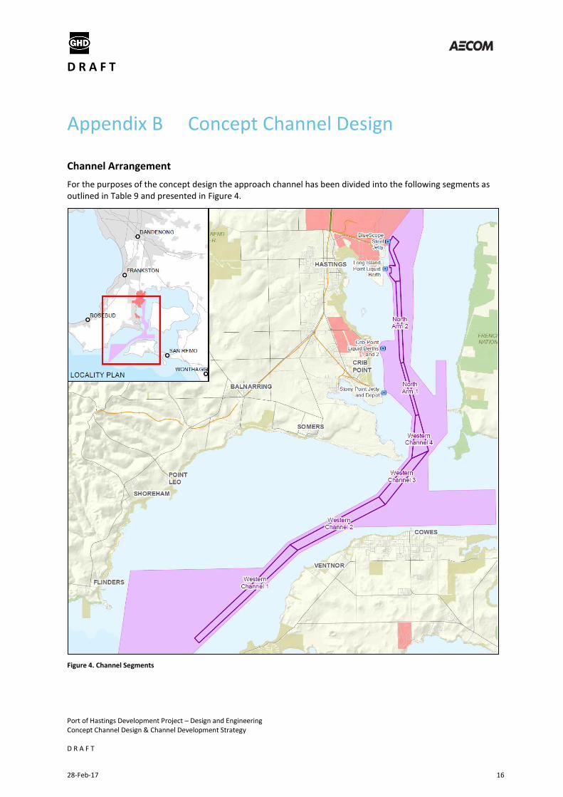
For the purposes of the concept design the approach channel has been divided into the following segments as outlined in Table 9 and presented in Figure 4.
Figure 4. Channel Segments
D R A F T
Port of Hastings Development Project – Design and Engineering Concept Channel Design & Channel Development Strategy D R A F T
28-Feb-17 17
Table 9. Channel Segments
Section No. Section Name Approx. Chainage (m) Beacons
1 Western Channel 1 0 – 15,075 Port limits to No. 7/8
2 Western Channel 2 15,075 – 21,050 No. 7/8 to No. 13/14
3 Western Channel 3 21,050 – 24,650 No. 13/14 to No. 17
4 Western Channel 4 24,650 – 27,000 No. 17 to No. 19/20
5 North Arm 1 27,000 – 30,100 No. 19/20 to No. 23/24
6 North Arm 2 30,100 – Swing Basin No. 23/24 to No. 35
Channel Width Factors
PIANC 2014 provides the following formula for determining the channel width for concept design:
- One-Way Channel Width (W) = WBM + 2ΣWi + WBr + WBg
- Two-Way Channel Width (W) = 2WBM + 2ΣWi + WBr + WBg +ΣWp
Where:
- WBM is the width of basic manoeuvring lane as a multiple of the design ship’s beam
- ΣWi additional widths to allow for the effect of wind, current, waves etc
- WBr, WBg is the bank clearance on the ‘red’ and ‘green’ sides of the channel
- ΣWp is the passing distance, comprising the sum of a separation distance between both manoeuvring lanes and an additional distance for traffic density.
A number of the criteria are subjective and the following sections discuss the rationale behind the criteria that has been used.
Inner/Outer Channel
PIANC 2014 gives the following description for outer and inner channels:
- An outer channel in open water and exposed to waves that can produce significant vertical ship motions of heave, pitch, and roll.
- An inner channel that lies in relatively sheltered waters and is not subject to wave action of any significance to large ships.
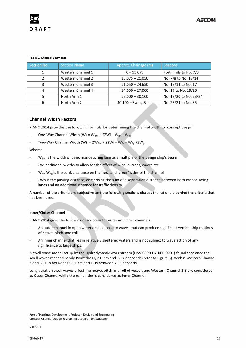
A swell wave model setup by the Hydrodynamic work stream (HAS-CEP0-HY-REP-0001) found that once the swell waves reached Sandy Point the Hs is 0.2m and Tp is 7 seconds (refer to Figure 5). Within Western Channel 2 and 3, Hs is between 0.7-1.3m and Tp is between 7-11 seconds.
Long duration swell waves affect the heave, pitch and roll of vessels and Western Channel 1-3 are considered as Outer Channel while the remainder is considered as Inner Channel.
D R A F T
Port of Hastings Development Project – Design and Engineering Concept Channel Design & Channel Development Strategy D R A F T
28-Feb-17 18
Figure 5. Hs and wave vectors for the largest wave height with a 0.01% probability of exceedance at waverider buoy Sweelwaves at Point Nepean (Figure 6 from HAS-CEP0-HY-REP-0001)
Basic Manoeuvring Lane
PIANC 2014 recommends moderate manoeuvring characteristics (1.5B) for container vessels and poor manoeuvring characteristics (1.8B) for container vessels.
Vessel Speed
PIANC characterises vessel speed into the following categories:
- Fast - Vs ≥ 12 kts
- Moderate - 8 kts ≤ Vs < 12 kts
- Slow - 5 kts ≤ Vs < 8 kts
Faster speeds result in a narrower channel because the ship is more controllable, however this is offset by the need to have a deeper channel. For container vessels both fast and moderate vessel speeds have been considered while for tankers only moderate speed has been considered. It was found that the differences between the speeds are minimal (0-3m for one way and 0-18m for two way) and the larger dimensions have been used.
Prevailing Cross Wind
Table 10 outlines the PIANC wind categories and the percentage exceedance for a 10 minute duration wind at an industrial site near Hastings (HAS-CEP0-HY-REP-0001). A wind category of moderate has been used.
Table 10. PIANC Wind Categories and Percentage Exceedance for an Industrial Site Near Hastings
PIANC wind category % Exceedance (10 min duration)
Mild - Vcw < 15 kts (< Beaufort 4) 20%
Moderate - 15 kts ≤ Vcw < 33 kts (Beaufort 4 - Beaufort 7) 0.1%
D R A F T
Port of Hastings Development Project – Design and Engineering Concept Channel Design & Channel Development Strategy D R A F T
28-Feb-17 19
Strong - 33 kts ≤ Vcw < 48 kts (Beaufort 7 - Beaufort 9) >0.1%
Prevailing Cross Current
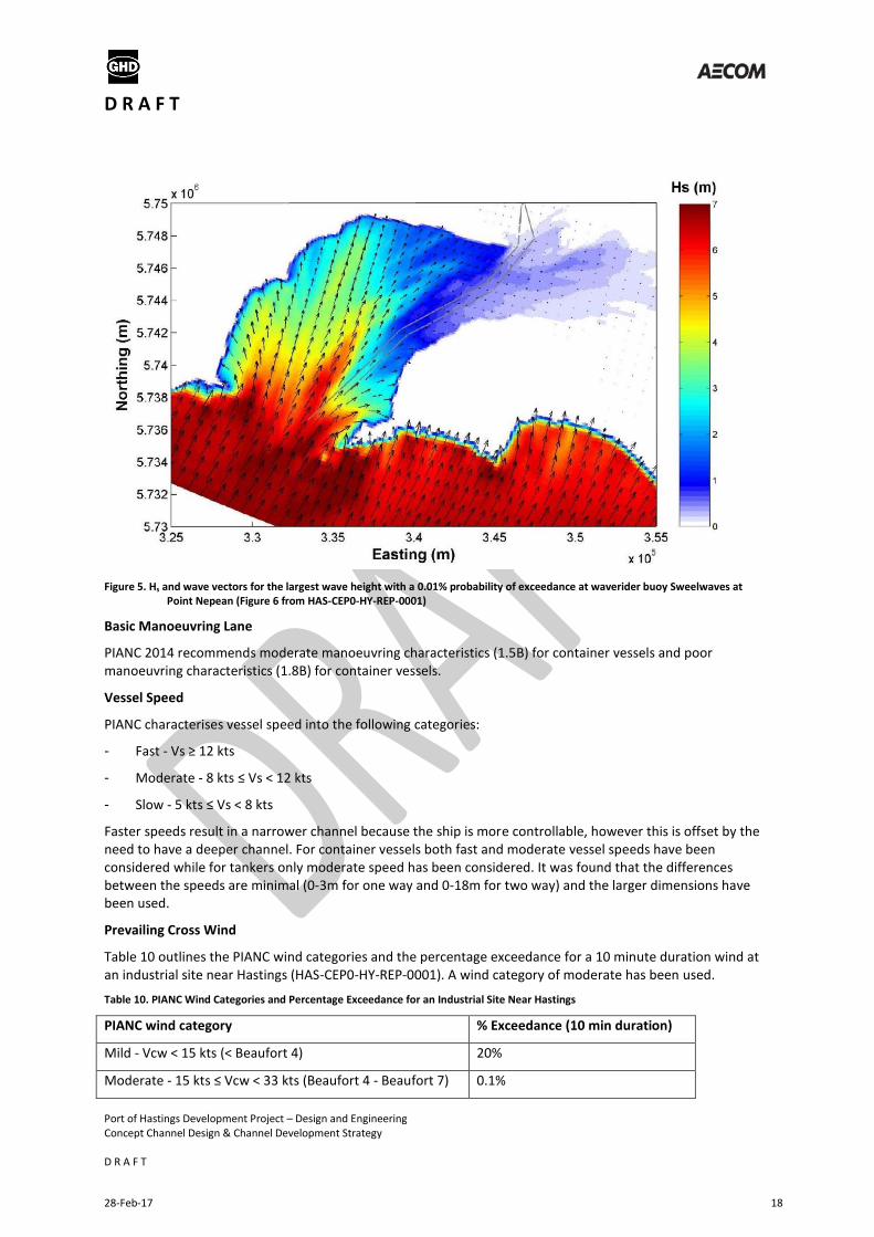
A 2-Dimensional depth-averaged hydrodynamic model of Western Port was run for a 30 day period by the Hydrodynamic workstream (HAS-CEP0-HY-REP-0001) and the modelled peak flood and ebb tides are outlined in Figure 5.
Figure 5. Modelled Peak Flood and Ebb Tides
PIANC categories the prevailing cross current as follows:
- Negligible Vcc < 0.2 kts
- Low 0.2 kts ≤ Vcc < 0.5 kts
- Moderate 0.5 kts ≤ Vcc < 1.5 kts
- Strong 1.5 kts ≤ Vcc < 2.0kts
The tide largely follows the path of the channel and the prevailing cross current has been considered the be Low.
Prevailing Longitudinal Current
PIANC categories the prevailing longitudinal current as follows:
- Low VlC < 1.5 kts
- Moderate 1.5 kts ≤ VlC < 3 kts
- Strong VlC ≥ 3 kts
D R A F T
Port of Hastings Development Project – Design and Engineering Concept Channel Design & Channel Development Strategy D R A F T
28-Feb-17 20
Figure 5 shows that the maximum current in the Western Channel is about 2kts whereas in the North Arm Channel the maximum current does not appear to exceed 1.5kts. Therefore the Western Channel has been categorised as Moderate and the North Arm has been categorised as Low
Beam and Stern Quartering Wave Height
PIANC categories the beam and stern quartering wave height as follows:
- Hs ≤ 1 m
- 1 m < Hs < 3 m
- Hs ≥ 3 m
Figure 5 outlines that waves with a Hs of up to 3m can occur in Western Channel 1, however they tend to be on the bow or stern based on the initial modelling undertaken. Given the exposure to waves within Western Channel 1 the largest wave category has been considered. Once past the first bend in the channel the waves have a significant wave height of less that 3m and the middle categories was considered for the remainder of the Western Channel.
Within the port near wind driven waves with a 1 year ARI was found to produce a significant wave height (Hs) of up to 1m with a period (Tp) of 3.5 seconds. A significant wave height of less than 1m was considered for the North Arm and Port Area.
Aids to Navigation
Excellent corresponds to paired lit buoys with radar reflectors, lit leading lights and VTS along with the availability of pilots, DGPS and ECDIS. It is assumed that this level of aids to navigation will be provided.
Depth of Waterway
In the Western Channel the depth is generally between 1.25-1.5T, however in some sections it is much deeper.
In the North Arm the depth will generally be < 1.15T
Width for Bank Clearance
Slopes in Western Channel segments C1-3 are generally much wider and deeper than required with slopes less than 1:10.
In Western channel segment 4 and up to the port area the slopes are around 1:5, however they are steeper in some sections, dredged slopes are likely to be around 1:3.
Traffic Density
For the constrained scenarios there will be on average more than 3 vessels per day from 2042 in the constrained Melbourne fully open scenario and from 2037 in the constrained stevedore move scenario. For the unconstrained scenario the maximum annual average is less than 3 vessels per day throughout the forecast period.