concept hdl digital simulation user guidestatistics.roma2.infn.it/~sabene/cadence...
TRANSCRIPT

Concept HDL Digital Simulation UserGuide
Product Version 14.2January 2002

1998-2002 Cadence Design Systems, Inc. All rights reserved.Printed in the United States of America.
Cadence Design Systems, Inc., 555 River Oaks Parkway, San Jose, CA 95134, USA
Trademarks: Trademarks and service marks of Cadence Design Systems, Inc. (Cadence) contained inthis document are attributed to Cadence with the appropriate symbol. For queries regarding Cadence’strademarks, contact the corporate legal department at the address shown above or call 1-800-862-4522.
All other trademarks are the property of their respective holders.
Restricted Print Permission: This publication is protected by copyright and any unauthorized use of thispublication may violate copyright, trademark, and other laws. Except as specified in this permissionstatement, this publication may not be copied, reproduced, modified, published, uploaded, posted,transmitted, or distributed in any way, without prior written permission from Cadence. This statement grantsyou permission to print one (1) hard copy of this publication subject to the following conditions:
1. The publication may be used solely for personal, informational, and noncommercial purposes;2. The publication may not be modified in any way;3. Any copy of the publication or portion thereof must include all original copyright, trademark, and other
proprietary notices and this permission statement; and4. Cadence reserves the right to revoke this authorization at any time, and any such use shall be
discontinued immediately upon written notice from Cadence.
Disclaimer: Information in this publication is subject to change without notice and does not represent acommitment on the part of Cadence. The information contained herein is the proprietary and confidentialinformation of Cadence or its licensors, and is supplied subject to, and may be used only by Cadence’scustomer in accordance with, a written agreement between Cadence and its customer. Except as may beexplicitly set forth in such agreement, Cadence does not make, and expressly disclaims, anyrepresentations or warranties as to the completeness, accuracy or usefulness of the information containedin this document. Cadence does not warrant that use of such information will not infringe any third partyrights, nor does Cadence assume any liability for damages or costs of any kind that may result from use ofsuch information.
Restricted Rights: Use, duplication, or disclosure by the Government is subject to restrictions as set forthin FAR52.227-14 and DFAR252.227-7013 et seq. or its successor.
Concept HDL Digital Simulation User Guide
Contents
Preface . . . . . . . . . . . . . . . . . . . . . . . . . . . . . . . . . . . . . . . . . . . . . . . . . . . . . . . . . . . . . 11
About This Manual . . . . . . . . . . . . . . . . . . . . . . . . . . . . . . . . . . . . . . . . . . . . . . . . . . . . . . 11Audience . . . . . . . . . . . . . . . . . . . . . . . . . . . . . . . . . . . . . . . . . . . . . . . . . . . . . . . . . . . 11Finding Information in This Manual . . . . . . . . . . . . . . . . . . . . . . . . . . . . . . . . . . . . . . 12
Related Documentation . . . . . . . . . . . . . . . . . . . . . . . . . . . . . . . . . . . . . . . . . . . . . . . . . . 13Typographical Conventions . . . . . . . . . . . . . . . . . . . . . . . . . . . . . . . . . . . . . . . . . . . . . . . 14
1Introduction . . . . . . . . . . . . . . . . . . . . . . . . . . . . . . . . . . . . . . . . . . . . . . . . . . . . . . . . . 1
Digital Simulation Overview . . . . . . . . . . . . . . . . . . . . . . . . . . . . . . . . . . . . . . . . . . . . . . . . 1
2Using the Verilog-XL Simulation Interface . . . . . . . . . . . . . . . . . . . . . . 5
Selecting the Verilog-XL Simulator . . . . . . . . . . . . . . . . . . . . . . . . . . . . . . . . . . . . . . . . . . 5Setting Up the Verilog-XL Simulation Interface . . . . . . . . . . . . . . . . . . . . . . . . . . . . . . . . . 6
Specifying Verilog-XL Netlisting Options . . . . . . . . . . . . . . . . . . . . . . . . . . . . . . . . . . . 7Specifying Verilog-XL Simulation Options . . . . . . . . . . . . . . . . . . . . . . . . . . . . . . . . . 12Specifying Verilog-XL Libraries . . . . . . . . . . . . . . . . . . . . . . . . . . . . . . . . . . . . . . . . . 13Providing a Testfixture for Verilog Simulation . . . . . . . . . . . . . . . . . . . . . . . . . . . . . . . 15Specifying Allegro SDF Annotation Options . . . . . . . . . . . . . . . . . . . . . . . . . . . . . . . . 18
Importing VHDL Models into the Verilog-XL Simulator . . . . . . . . . . . . . . . . . . . . . . . . . . 19VHDL Cosimulation . . . . . . . . . . . . . . . . . . . . . . . . . . . . . . . . . . . . . . . . . . . . . . . . . . . . . 20Providing Instance-Based Binding Support . . . . . . . . . . . . . . . . . . . . . . . . . . . . . . . . . . . 20Simulating Designs with SWIFT and Hardware Models . . . . . . . . . . . . . . . . . . . . . . . . . 21Running the Verilog-XL Simulator . . . . . . . . . . . . . . . . . . . . . . . . . . . . . . . . . . . . . . . . . . 24
Cross Probing between Concept HDL and Verilog-XL . . . . . . . . . . . . . . . . . . . . . . . . 25
3Using the NC Verilog Simulation Interface. . . . . . . . . . . . . . . . . . . . . 27
Selecting the NC Verilog Simulator . . . . . . . . . . . . . . . . . . . . . . . . . . . . . . . . . . . . . . . . . 27
January 2002 3 Product Version 14.2

Concept HDL Digital Simulation User Guide
Setting Up the NC Verilog Simulation Interface . . . . . . . . . . . . . . . . . . . . . . . . . . . . . . . . 28Specifying NC Verilog Netlisting Options . . . . . . . . . . . . . . . . . . . . . . . . . . . . . . . . . . 29Specifying NC Verilog Simulation Options . . . . . . . . . . . . . . . . . . . . . . . . . . . . . . . . . 31Providing a Testfixture for Verilog Simulation . . . . . . . . . . . . . . . . . . . . . . . . . . . . . . . 32Specifying SDF Annotation Options . . . . . . . . . . . . . . . . . . . . . . . . . . . . . . . . . . . . . . 34
Importing VHDL Models into the NC Verilog Simulator . . . . . . . . . . . . . . . . . . . . . . . . . . 35VHDL Cosimulation . . . . . . . . . . . . . . . . . . . . . . . . . . . . . . . . . . . . . . . . . . . . . . . . . . . . . 36Running the NC Verilog Simulator . . . . . . . . . . . . . . . . . . . . . . . . . . . . . . . . . . . . . . . . . . 36
Cross Probing between Concept HDL and NC Verilog . . . . . . . . . . . . . . . . . . . . . . . 36
4Using the Simulation Interface for Running NC Verilog in theVerilog-XL Mode . . . . . . . . . . . . . . . . . . . . . . . . . . . . . . . . . . . . . . . . . . . . . . . . . . 39
Selecting the Option for Running NC Verilog in the Verilog-XL Mode . . . . . . . . . . . . . . . 39Setting Up the Simulation Interface for Running NC Verilog in Verilog-XL Mode . . . . . . 40
Specifying Netlisting Options . . . . . . . . . . . . . . . . . . . . . . . . . . . . . . . . . . . . . . . . . . . 41Specifying Simulation Options . . . . . . . . . . . . . . . . . . . . . . . . . . . . . . . . . . . . . . . . . . 42Specifying Verilog Libraries . . . . . . . . . . . . . . . . . . . . . . . . . . . . . . . . . . . . . . . . . . . . 43Providing a Testfixture for Verilog Simulation . . . . . . . . . . . . . . . . . . . . . . . . . . . . . . . 45Specifying SDF Annotation Options . . . . . . . . . . . . . . . . . . . . . . . . . . . . . . . . . . . . . . 48
Running the NC Verilog Simulator in Verilog-XL Mode . . . . . . . . . . . . . . . . . . . . . . . . . . 50Cross Probing between Concept HDL and NC Verilog . . . . . . . . . . . . . . . . . . . . . . . 50
5Using the Leapfrog Simulation Interface. . . . . . . . . . . . . . . . . . . . . . . 53
Selecting the Leapfrog Simulator . . . . . . . . . . . . . . . . . . . . . . . . . . . . . . . . . . . . . . . . . . . 53Setting Up the Leapfrog Simulation Interface . . . . . . . . . . . . . . . . . . . . . . . . . . . . . . . . . 54
Specifying Leapfrog Netlisting Options . . . . . . . . . . . . . . . . . . . . . . . . . . . . . . . . . . . 54Specifying Leapfrog Simulation Options . . . . . . . . . . . . . . . . . . . . . . . . . . . . . . . . . . 57Specifying Leapfrog Compiler (cv) Options . . . . . . . . . . . . . . . . . . . . . . . . . . . . . . . . 58Specifying Leapfrog Elaborator (ev) Options . . . . . . . . . . . . . . . . . . . . . . . . . . . . . . . 59Specifying Leapfrog Simulator (sv) Options . . . . . . . . . . . . . . . . . . . . . . . . . . . . . . . . 61Providing a Testfixture for VHDL Simulation . . . . . . . . . . . . . . . . . . . . . . . . . . . . . . . . 62Specifying Allegro SDF Annotation Options . . . . . . . . . . . . . . . . . . . . . . . . . . . . . . . . 63
January 2002 4 Product Version 14.2
Concept HDL Digital Simulation User Guide
Importing Verilog Models into the Leapfrog VHDL Simulator . . . . . . . . . . . . . . . . . . . . . 64Verilog Cosimulation . . . . . . . . . . . . . . . . . . . . . . . . . . . . . . . . . . . . . . . . . . . . . . . . . . . . 64Running the Leapfrog Simulator . . . . . . . . . . . . . . . . . . . . . . . . . . . . . . . . . . . . . . . . . . . 64
Cross Probing between Concept HDL and Leapfrog . . . . . . . . . . . . . . . . . . . . . . . . . 65
6Using the NC VHDL Simulation Interface. . . . . . . . . . . . . . . . . . . . . . 67
Selecting the NC VHDL Simulator . . . . . . . . . . . . . . . . . . . . . . . . . . . . . . . . . . . . . . . . . . 67Setting Up the NC VHDL Simulation Interface . . . . . . . . . . . . . . . . . . . . . . . . . . . . . . . . . 68
Specifying NC VHDL Netlisting Options . . . . . . . . . . . . . . . . . . . . . . . . . . . . . . . . . . . 69Specifying NC VHDL Simulation Options . . . . . . . . . . . . . . . . . . . . . . . . . . . . . . . . . . 71Providing a Testfixture for VHDL Simulation . . . . . . . . . . . . . . . . . . . . . . . . . . . . . . . . 72Specifying Allegro SDF Annotation Options . . . . . . . . . . . . . . . . . . . . . . . . . . . . . . . . 73
Importing Verilog Models into the NC VHDL Simulator . . . . . . . . . . . . . . . . . . . . . . . . . . 75Simulating Designs with SWIFT and Hardware Models . . . . . . . . . . . . . . . . . . . . . . . . . 75Running the NC VHDL Simulator . . . . . . . . . . . . . . . . . . . . . . . . . . . . . . . . . . . . . . . . . . 75
Cross Probing between Concept HDL and NC VHDL . . . . . . . . . . . . . . . . . . . . . . . . 76
7Supporting Third-Party Verilog and VHDL Simulators . . . . . . . 78
Supporting Third-Party Verilog Simulators . . . . . . . . . . . . . . . . . . . . . . . . . . . . . . . . . . . . 78Selecting the Third-Party Verilog Simulator Option . . . . . . . . . . . . . . . . . . . . . . . . . . 78Specifying Netlisting Options for Third-Party Verilog Simulators . . . . . . . . . . . . . . . . 79Generating the Netlist for Third-Party Verilog Simulators . . . . . . . . . . . . . . . . . . . . . . 81Files Required by Third-Party Verilog Simulators . . . . . . . . . . . . . . . . . . . . . . . . . . . . 82
Supporting Third-Party VHDL Simulators . . . . . . . . . . . . . . . . . . . . . . . . . . . . . . . . . . . . 82Selecting the Third-Party VHDL Simulator Option . . . . . . . . . . . . . . . . . . . . . . . . . . . 82Specifying Netlisting Options for Third-Party VHDL Simulators . . . . . . . . . . . . . . . . . 83Generating the Netlist for Third-Party VHDL Simulators . . . . . . . . . . . . . . . . . . . . . . 85Files Required by Third-Party VHDL Simulators . . . . . . . . . . . . . . . . . . . . . . . . . . . . 86
8Asymmetrical Parts . . . . . . . . . . . . . . . . . . . . . . . . . . . . . . . . . . . . . . . . . . . . . . . 87
Split Part . . . . . . . . . . . . . . . . . . . . . . . . . . . . . . . . . . . . . . . . . . . . . . . . . . . . . . . . . . . 87
January 2002 5 Product Version 14.2

Concept HDL Digital Simulation User Guide
Asymmetrical Part . . . . . . . . . . . . . . . . . . . . . . . . . . . . . . . . . . . . . . . . . . . . . . . . . . . 88MultiSection Parts with Common Pins . . . . . . . . . . . . . . . . . . . . . . . . . . . . . . . . . . . . 90
Simulation Properties for the Split Parts . . . . . . . . . . . . . . . . . . . . . . . . . . . . . . . . . . . . . 90Using the SPLIT_INST Property . . . . . . . . . . . . . . . . . . . . . . . . . . . . . . . . . . . . . . . . 90Using the SPLIT_INST_NAME Property . . . . . . . . . . . . . . . . . . . . . . . . . . . . . . . . . . 91Working with the SPLIT_INST_NAME and the SPLIT_INST Properties . . . . . . . . . . 92
Examples . . . . . . . . . . . . . . . . . . . . . . . . . . . . . . . . . . . . . . . . . . . . . . . . . . . . . . . . . . . . . 95Example of Split Parts . . . . . . . . . . . . . . . . . . . . . . . . . . . . . . . . . . . . . . . . . . . . . . . . 95Example of Asymmetrical Part . . . . . . . . . . . . . . . . . . . . . . . . . . . . . . . . . . . . . . . . . . 99Example of Multi Section Parts . . . . . . . . . . . . . . . . . . . . . . . . . . . . . . . . . . . . . . . . 103
Working with Wrappers . . . . . . . . . . . . . . . . . . . . . . . . . . . . . . . . . . . . . . . . . . . . . . . . . 111
ADialog Box Reference . . . . . . . . . . . . . . . . . . . . . . . . . . . . . . . . . . . . . . . . . . . 113
Choose Simulator . . . . . . . . . . . . . . . . . . . . . . . . . . . . . . . . . . . . . . . . . . . . . . . . . . . . . 113Start Simulator . . . . . . . . . . . . . . . . . . . . . . . . . . . . . . . . . . . . . . . . . . . . . . . . . . . . . . . . 113Netlist (Verilog) . . . . . . . . . . . . . . . . . . . . . . . . . . . . . . . . . . . . . . . . . . . . . . . . . . . . . . . 114Simulation . . . . . . . . . . . . . . . . . . . . . . . . . . . . . . . . . . . . . . . . . . . . . . . . . . . . . . . . . . . 121Library . . . . . . . . . . . . . . . . . . . . . . . . . . . . . . . . . . . . . . . . . . . . . . . . . . . . . . . . . . . . . . 124Stimulus (Verilog) . . . . . . . . . . . . . . . . . . . . . . . . . . . . . . . . . . . . . . . . . . . . . . . . . . . . . . 125Allegro SDF (Verilog) . . . . . . . . . . . . . . . . . . . . . . . . . . . . . . . . . . . . . . . . . . . . . . . . . . . 127VHDL Netlist . . . . . . . . . . . . . . . . . . . . . . . . . . . . . . . . . . . . . . . . . . . . . . . . . . . . . . . . . 128Leapfrog: Simulation . . . . . . . . . . . . . . . . . . . . . . . . . . . . . . . . . . . . . . . . . . . . . . . . . . . 133Leapfrog: Compile . . . . . . . . . . . . . . . . . . . . . . . . . . . . . . . . . . . . . . . . . . . . . . . . . . . . . 134Leapfrog: Elaborate . . . . . . . . . . . . . . . . . . . . . . . . . . . . . . . . . . . . . . . . . . . . . . . . . . . . 136Leapfrog: Simulate . . . . . . . . . . . . . . . . . . . . . . . . . . . . . . . . . . . . . . . . . . . . . . . . . . . . . 138VHDL Stimulus . . . . . . . . . . . . . . . . . . . . . . . . . . . . . . . . . . . . . . . . . . . . . . . . . . . . . . . 139Allegro SDF (VHDL) . . . . . . . . . . . . . . . . . . . . . . . . . . . . . . . . . . . . . . . . . . . . . . . . . . . 140NC Verilog: Simulation . . . . . . . . . . . . . . . . . . . . . . . . . . . . . . . . . . . . . . . . . . . . . . . . . . 141NC VHDL: Simulation . . . . . . . . . . . . . . . . . . . . . . . . . . . . . . . . . . . . . . . . . . . . . . . . . . 143
January 2002 6 Product Version 14.2

Concept HDL Digital Simulation User Guide
BRunning NC Verilog and NC VHDL Simulators from theCommand Line. . . . . . . . . . . . . . . . . . . . . . . . . . . . . . . . . . . . . . . . . . . . . . . . . . . 145
CSimulation Configurations . . . . . . . . . . . . . . . . . . . . . . . . . . . . . . . . . . . . . . 148
Creating a Configuration . . . . . . . . . . . . . . . . . . . . . . . . . . . . . . . . . . . . . . . . . . . . . . . . 149Editing a Configuration . . . . . . . . . . . . . . . . . . . . . . . . . . . . . . . . . . . . . . . . . . . . . . . . . 150
DSimulation Parameters . . . . . . . . . . . . . . . . . . . . . . . . . . . . . . . . . . . . . . . . . . 152
Specifying Parameters for Verilog Simulation . . . . . . . . . . . . . . . . . . . . . . . . . . . . . . . . 152Specifying Verilog Parameters Using \PARAM . . . . . . . . . . . . . . . . . . . . . . . . . . . . . 152Defining Parameters in the cdsprop.paf File . . . . . . . . . . . . . . . . . . . . . . . . . . . . . . . 153Specifying Verilog Parameters using the VLOG_PARAM Property . . . . . . . . . . . . . 154Specifying the Type of Verilog Parameter for Multiple Schematic Instances . . . . . . 155Passing the Value of a Verilog Parameter from a Top Level Design to a Lower Level Design
. . . . . . . . . . . . . . . . . . . . . . . . . . . . . . . . . . . . . . . . . . . . . . . . . . . . . . . . . . . . . . . . . 156Precedence for Determining the Type of a Parameter . . . . . . . . . . . . . . . . . . . . . . . 157Specifying Verilog Parameters on Symbols . . . . . . . . . . . . . . . . . . . . . . . . . . . . . . . 157Case Sensitivity of Parameters . . . . . . . . . . . . . . . . . . . . . . . . . . . . . . . . . . . . . . . . 158
Specifying Generics for VHDL Simulation . . . . . . . . . . . . . . . . . . . . . . . . . . . . . . . . . . . 158Passing Values of Generics from an Upper Level Design to a Lower Level Design . 160Case Sensitivity of Generics . . . . . . . . . . . . . . . . . . . . . . . . . . . . . . . . . . . . . . . . . . 160
Passing the Value of One Parameter or Generic to Another . . . . . . . . . . . . . . . . . . . . . 161
ESimulation Properties . . . . . . . . . . . . . . . . . . . . . . . . . . . . . . . . . . . . . . . . . . . 162
NO_REP_PRIM . . . . . . . . . . . . . . . . . . . . . . . . . . . . . . . . . . . . . . . . . . . . . . . . . . . . 164MODEL_DIR . . . . . . . . . . . . . . . . . . . . . . . . . . . . . . . . . . . . . . . . . . . . . . . . . . . . . . 166MODEL_FILE . . . . . . . . . . . . . . . . . . . . . . . . . . . . . . . . . . . . . . . . . . . . . . . . . . . . . . 167PORT_ORDER . . . . . . . . . . . . . . . . . . . . . . . . . . . . . . . . . . . . . . . . . . . . . . . . . . . . . 169REMOVE . . . . . . . . . . . . . . . . . . . . . . . . . . . . . . . . . . . . . . . . . . . . . . . . . . . . . . . . . 170
January 2002 7 Product Version 14.2
Concept HDL Digital Simulation User Guide
SIM_BIND_VIEW . . . . . . . . . . . . . . . . . . . . . . . . . . . . . . . . . . . . . . . . . . . . . . . . . . . 174SIM_MAP_VIEW . . . . . . . . . . . . . . . . . . . . . . . . . . . . . . . . . . . . . . . . . . . . . . . . . . . 175SIZE . . . . . . . . . . . . . . . . . . . . . . . . . . . . . . . . . . . . . . . . . . . . . . . . . . . . . . . . . . . . . 175SPLIT_INST . . . . . . . . . . . . . . . . . . . . . . . . . . . . . . . . . . . . . . . . . . . . . . . . . . . . . . . 176SPLIT_INST_NAME . . . . . . . . . . . . . . . . . . . . . . . . . . . . . . . . . . . . . . . . . . . . . . . . . 176VERILOG_LIB . . . . . . . . . . . . . . . . . . . . . . . . . . . . . . . . . . . . . . . . . . . . . . . . . . . . . 177VERILOG_MODEL . . . . . . . . . . . . . . . . . . . . . . . . . . . . . . . . . . . . . . . . . . . . . . . . . . 178VERILOG_NAME . . . . . . . . . . . . . . . . . . . . . . . . . . . . . . . . . . . . . . . . . . . . . . . . . . . 180VHDL_MODEL . . . . . . . . . . . . . . . . . . . . . . . . . . . . . . . . . . . . . . . . . . . . . . . . . . . . . 180VHDL_NAME . . . . . . . . . . . . . . . . . . . . . . . . . . . . . . . . . . . . . . . . . . . . . . . . . . . . . . 182Specifying User-Defined Properties in Verilog Map Files . . . . . . . . . . . . . . . . . . . . . 182Specifying User-Defined Properties in VHDL Map Files . . . . . . . . . . . . . . . . . . . . . 184
Case Sensitivity of Property Values . . . . . . . . . . . . . . . . . . . . . . . . . . . . . . . . . . . . . . . . 184Case-Insensitive Property Values . . . . . . . . . . . . . . . . . . . . . . . . . . . . . . . . . . . . . . . . . 186Case-Insensitive Property Names . . . . . . . . . . . . . . . . . . . . . . . . . . . . . . . . . . . . . . . . . 187
FMap Files . . . . . . . . . . . . . . . . . . . . . . . . . . . . . . . . . . . . . . . . . . . . . . . . . . . . . . . . . 190
Verilog Map File . . . . . . . . . . . . . . . . . . . . . . . . . . . . . . . . . . . . . . . . . . . . . . . . . . . . . . . 190PRIMITIVE Section . . . . . . . . . . . . . . . . . . . . . . . . . . . . . . . . . . . . . . . . . . . . . . . . . 191PIN MAP Section . . . . . . . . . . . . . . . . . . . . . . . . . . . . . . . . . . . . . . . . . . . . . . . . . . . 194
Examples of Verilog Map Files . . . . . . . . . . . . . . . . . . . . . . . . . . . . . . . . . . . . . . . . . . . 196Verilog Model without Sections . . . . . . . . . . . . . . . . . . . . . . . . . . . . . . . . . . . . . . . . 196Verilog Model with Sections . . . . . . . . . . . . . . . . . . . . . . . . . . . . . . . . . . . . . . . . . . . 197SWIFT Model with Sections . . . . . . . . . . . . . . . . . . . . . . . . . . . . . . . . . . . . . . . . . . . 198
VHDL Map File . . . . . . . . . . . . . . . . . . . . . . . . . . . . . . . . . . . . . . . . . . . . . . . . . . . . . . . 199VHDL Map File Format . . . . . . . . . . . . . . . . . . . . . . . . . . . . . . . . . . . . . . . . . . . . . . . 199PRIMITIVE Section . . . . . . . . . . . . . . . . . . . . . . . . . . . . . . . . . . . . . . . . . . . . . . . . . 199PIN MAP Section . . . . . . . . . . . . . . . . . . . . . . . . . . . . . . . . . . . . . . . . . . . . . . . . . . . 202
Examples of VHDL Map Files . . . . . . . . . . . . . . . . . . . . . . . . . . . . . . . . . . . . . . . . . . . . 204VHDL Model Without Sections . . . . . . . . . . . . . . . . . . . . . . . . . . . . . . . . . . . . . . . . . 204VHDL Model with Sections . . . . . . . . . . . . . . . . . . . . . . . . . . . . . . . . . . . . . . . . . . . . 205VHDL Model for Asymmetrical Parts . . . . . . . . . . . . . . . . . . . . . . . . . . . . . . . . . . . . 205
January 2002 8 Product Version 14.2
Concept HDL Digital Simulation User Guide
GSDF Files . . . . . . . . . . . . . . . . . . . . . . . . . . . . . . . . . . . . . . . . . . . . . . . . . . . . . . . . . 207
$SDF_annotate . . . . . . . . . . . . . . . . . . . . . . . . . . . . . . . . . . . . . . . . . . . . . . . . . . . . . . . 207INTERCONNECT Keyword . . . . . . . . . . . . . . . . . . . . . . . . . . . . . . . . . . . . . . . . . . . . . . 208
Interconnect Example . . . . . . . . . . . . . . . . . . . . . . . . . . . . . . . . . . . . . . . . . . . . . . . . 209
HFiles Created in Run Directory . . . . . . . . . . . . . . . . . . . . . . . . . . . . . . . . . 211
script.cmd . . . . . . . . . . . . . . . . . . . . . . . . . . . . . . . . . . . . . . . . . . . . . . . . . . . . . . . . . . . 212verilog.cmd . . . . . . . . . . . . . . . . . . . . . . . . . . . . . . . . . . . . . . . . . . . . . . . . . . . . . . . . . . 213compilescript . . . . . . . . . . . . . . . . . . . . . . . . . . . . . . . . . . . . . . . . . . . . . . . . . . . . . . . . . 213<design_name>.f . . . . . . . . . . . . . . . . . . . . . . . . . . . . . . . . . . . . . . . . . . . . . . . . . . . . . . 215<design_name>.v . . . . . . . . . . . . . . . . . . . . . . . . . . . . . . . . . . . . . . . . . . . . . . . . . . . . . 216<design_name>.vhd . . . . . . . . . . . . . . . . . . . . . . . . . . . . . . . . . . . . . . . . . . . . . . . . . . . 216netassembler.log . . . . . . . . . . . . . . . . . . . . . . . . . . . . . . . . . . . . . . . . . . . . . . . . . . . . . . 216ncvlog.log . . . . . . . . . . . . . . . . . . . . . . . . . . . . . . . . . . . . . . . . . . . . . . . . . . . . . . . . . . . . 217ncvhdl.log . . . . . . . . . . . . . . . . . . . . . . . . . . . . . . . . . . . . . . . . . . . . . . . . . . . . . . . . . . . . 217ncelab.log . . . . . . . . . . . . . . . . . . . . . . . . . . . . . . . . . . . . . . . . . . . . . . . . . . . . . . . . . . . . 217ncsim.log . . . . . . . . . . . . . . . . . . . . . . . . . . . . . . . . . . . . . . . . . . . . . . . . . . . . . . . . . . . . 217verilog.log . . . . . . . . . . . . . . . . . . . . . . . . . . . . . . . . . . . . . . . . . . . . . . . . . . . . . . . . . . . 217detail.log . . . . . . . . . . . . . . . . . . . . . . . . . . . . . . . . . . . . . . . . . . . . . . . . . . . . . . . . . . . . 217HierEditor.log . . . . . . . . . . . . . . . . . . . . . . . . . . . . . . . . . . . . . . . . . . . . . . . . . . . . . . . . . 217hdl.var . . . . . . . . . . . . . . . . . . . . . . . . . . . . . . . . . . . . . . . . . . . . . . . . . . . . . . . . . . . . . . 218
Index. . . . . . . . . . . . . . . . . . . . . . . . . . . . . . . . . . . . . . . . . . . . . . . . . . . . . . . . . . . . . . . 219
January 2002 9 Product Version 14.2

Concept HDL Digital Simulation User Guide
January 2002 10 Product Version 14.2

Concept HDL Digital Simulation User Guide
Preface
This preface contains the following sections:
■ About This Manual on page 11
■ Related Documentation on page 13
■ Typographical Conventions on page 14
About This Manual
This manual describes the simulation interface provided by Concept HDL for setting up andrunning the following simulators for performing digital simulation:
■ Verilog-XL simulator
■ Affirma NC Verilog simulator
■ Leapfrog VHDL simulator
■ Affirma NC VHDL simulator
The digital simulation interface also supports third-party Verilog and VHDL simulators byallowing you to generate the netlist that you can use with third-party simulators.
Audience
This manual is for designers interested in simulating a schematic-based mixed level designentered in Concept HDL. Familiarity with the Concept HDL schematic editor, Verilog HDL,VHDL and the Verilog-XL, NC Verilog, Leapfrog, and NC VHDL simulators is assumed.
For more information on Concept HDL and the simulators, see the documentation listed inthe Related Documentation section.
January 2002 11 Product Version 14.2

Concept HDL Digital Simulation User GuidePreface
Finding Information in This Manual
The following table summarizes the topics covered in this manual.
If you want to... Read...
See an overview of the digital simulationprocess
Chapter 1, “Introduction”
Setup the simulation interface for the Verilog-XL simulator and simulate the design usingVerilog-XL
Chapter 2, “Using the Verilog-XL SimulationInterface”
Setup the simulation interface for the NCVerilog simulator and simulate the designusing NC Verilog
Chapter 3, “Using the NC Verilog SimulationInterface”
Setup the simulation interface for running theNC Verilog simulator in the Verilog-XL mode
Chapter 4, “Using the Simulation Interfacefor Running NC Verilog in the Verilog-XLMode,”
Setup the simulation interface for theLeapfrog VHDL simulator and simulate thedesign using Leapfrog
Chapter 5, “Using the Leapfrog SimulationInterface,”
Setup the simulation interface for the NCVHDL simulator and simulate the designusing NC VHDL
Chapter 6, “Using the NC VHDL SimulationInterface”
Generate the netlist for use with third-partyVerilog and VHDL simulators
Chapter 7, “Supporting Third-Party Verilogand VHDL Simulators”
Run the NC Verilog and NC VHDL simulatorsfrom the command line
Appendix B, “Running NC Verilog and NCVHDL Simulators from the Command Line”
Know about simulation configurations andhow to create and edit simulationconfigurations
Appendix C, “Simulation Configurations”
Learn how to use simulation parameters andproperties in your design
Appendix D, “Simulation Parameters”
Appendix E, “Simulation Properties”
Understand Verilog and VHDL map files Appendix F, “Map Files”
January 2002 12 Product Version 14.2

Concept HDL Digital Simulation User GuidePreface
Related Documentation
The following manuals give you information about other tools used during the digitalsimulation process:
If you want to know... Read...
How to use Concept HDL to enterschematics
Concept HDL User Guide
More about Concept HDL digital libraries Concept HDL Libraries Reference
More about properties supported byCadence PCB design software.
PCB Systems Properties Reference
More about using the Verilog-XL simulator Verilog-XL User Guide
Verilog-XL Reference
Verilog-XL Modeling Style Guide
Verilog-XL Configuration Guide
More about using the Affirma NC Verilogsimulator
Affirma NC Verilog Simulator Help
Affirma NC Verilog SimulatorConfiguration Guide
More about using the Leapfrog VHDLsimulator
Leapfrog VHDL Simulator User Guide
Leapfrog VHDL Simulator Reference
Leapfrog Notebook User Guide
Leapfrog C Interface User Guide
Leapfrog Hierarchy Browser (DesignView) User Guide
Leapfrog VHDL Simulator ConfigurationGuide
More about using the Affirma NC VHDLsimulator
Affirma NC VHDL Simulator Help
Affirma NC VHDL Simulator Tutorial
Affirma NC VHDL SimulatorConfiguration Guide
How to work in the SimVision analysisenvironment for Cadence simulators
Affirma SimVision AnalysisEnvironment User Guide
How to use the Signalscan Waveswaveform viewing tool
Signalscan Waves User Guide
January 2002 13 Product Version 14.2

Concept HDL Digital Simulation User GuidePreface
Typographical Conventions
The following conventions are used throughout this document:
More about SDF files SDF Annotator User Guide
How to use the PLI Wizard utility to buildthe simulator
PLI Wizard User Guide
■ About the hardware modeling processusing hardware models from the LogicModeling Group of Synopsys, Inc.
■ About the crshell utility (suppliedwith Hardware Modeling Interface, aproduct of the Logic Modeling Groupof Synopsys, Inc) that creates a modeldescription in Verilog HDL to be usedwith the hardware modeler
Hardware Modeling Interface ReferenceManual and User Guide
Convention Example Description
<> <projectfile.cpm> A required item in thecommand line. For example<projectfile.cpm> in thecommand line means thatyou have to specify theproject file name.
[] [-sdf <path to SDFfile>]
Optional item orcommand-line argument
<|> <y|n> Specify one of the givenchoices
If you want to know... Read...
January 2002 14 Product Version 14.2

Concept HDL Digital Simulation User Guide
1Introduction
Concept HDL provides a top-down digital design and simulation environment that lets youuse multiple simulation engines on the same design. Concept HDL supports the digitalsimulation of designs using:
■ Verilog-XL simulator
■ Affirma NC Verilog simulator
■ Leapfrog VHDL simulator
■ Affirma NC VHDL simulator
Concept HDL provides a simulation interface for setting up and running the simulators. Youhave to select the simulator you want to use and set up the options for running the simulator.During simulation, you can perform cross probing between the simulator and Concept HDLto quickly debug your design.
You can run the Affirma NC Verilog simulator in the Verilog-XL mode. This means that youcan run the NC Verilog simulator using the options you have setup in the simulation interfacefor Verilog-XL. For more information, see Chapter 4, “Using the Simulation Interface forRunning NC Verilog in the Verilog-XL Mode,”
Concept HDL also supports third party Verilog and VHDL simulators by allowing you togenerate the netlist that you can use with third party simulators. For more information, seeChapter 7, “Supporting Third-Party Verilog and VHDL Simulators.”
Digital Simulation Overview
Digital simulation in Concept HDL involves the following tasks:
1. Create schematics for your design using Concept HDL.
2. Select the simulator you want to use.
3. Setup the options for running the simulator. For example, if you are using the Verilog-XLsimulator, you can do the following:
January 2002 1 Product Version 14.2

Concept HDL Digital Simulation User GuideIntroduction
❑ Specify options for netlisting the design.
❑ Specify options for performing SDF backannotation.
❑ Provide testfixture for simulation.
❑ Specify options for running the Verilog-XL simulator.
4. Create a new design configuration, or modify an existing design configuration using theHierarchy Editor tool. For more information, see Appendix C, “SimulationConfigurations.”
5. Run simulation on your design using the specified design configuration. The design isnetlisted and compiled, and the simulator is invoked.
6. Simulate your design using the simulator.
7. Browse waveforms and debug your design. You can perform cross probing between thesimulator and Concept HDL to quickly debug your design.
Figure 1-1 on page 2 explains the Verilog-XL simulation flow. Figure 1-2 on page 3 explainsthe NC Verilog simulation flow. Figure 1-3 on page 3explains the NC VHDL and Leapfrogsimulation flow.
Figure 1-1 Verilog-XL Simulation Flow
Concept HDL
Packager-XLSimulationHierarchy
Allegro/SigNoise
Editor Interface
Physicallayoutbinding
Bindingforsimulation
Verilog Netlist Verilog Netlist
Wire delaysfor timingverification
Packagerfiles
Verilog-XL
Library models,wire delays,stimulus andsimulator options
Create/editVerilogconfiguration
January 2002 2 Product Version 14.2

Concept HDL Digital Simulation User GuideIntroduction
Figure 1-2 NC Verilog Simulation Flow
Figure 1-3 VHDL Simulation Flow
Concept HDL
Packager-XLSimulationHierarchy
Allegro/SigNoise
Editor Interface
Physicallayoutbinding
Design Netlist Design Netlist
Wire delaysfor timingverification
Packagerfiles
NC Verilog
library models,wire delays,stimulus andsimulator options
compilescriptSimulation netlist,
Verilogconfiguration
Create/edit
Concept HDL
Packager-XLSimulationHierarchy
Allegro/SigNoise
Editor Interface
Physicallayoutbinding
Verilog Netlist VHDL Netlist
Wire delaysfor timingverification
Packagerfiles
NC VHDL
wire delays,stimulus and options for compiler,elaborator andsimulator
Compilescript
VHDLconfiguration
Create/edit
Leapfrog
January 2002 3 Product Version 14.2

Concept HDL Digital Simulation User GuideIntroduction
January 2002 4 Product Version 14.2
Concept HDL Digital Simulation User Guide
2Using the Verilog-XL Simulation Interface
You can simulate your Verilog designs from Concept HDL using the Verilog-XL simulator.Performing digital simulation using the Verilog-XL simulator involves the following tasks:
1. Selecting the Verilog-XL Simulator
2. Setting Up the Verilog-XL Simulation Interface
3. Creating a new design configuration or modifying an existing design configuration usingthe Hierarchy Editor tool. For more information, see Appendix C, “SimulationConfigurations.”
4. Running a simulation on your design using the specified design configuration. Thedesign is netlisted and compiled, and the Verilog-XL simulator is invoked. For moreinformation, see Running the Verilog-XL Simulator.
5. Simulating your design using the simulator.
6. Browsing waveforms and debugging your design. You can perform cross probingbetween Concept HDL and Verilog-XL to quickly debug your design.
Selecting the Verilog-XL Simulator
To use the Verilog-XL simulator for simulating a design, you have to select the Verilog-XLsimulator. To do this:
1. Start Project Manager.
2. Open the project.
3. Select Tools > Setup.
The Project Setup window appears.
4. Select the Tools tab.
5. Click Simulation Setup.
January 2002 5 Product Version 14.2

Concept HDL Digital Simulation User GuideUsing the Verilog-XL Simulation Interface
The Choose Simulator dialog box appears.
6. Select the Verilog-XL option and click OK.
Setting Up the Verilog-XL Simulation Interface
You can set up the following Verilog-XL simulator options from the Simulation Interface:
■ Specify netlisting options.
For more information, see Specifying Verilog-XL Netlisting Options on page 7.
■ Specify simulation options.
For more information, see Specifying Verilog-XL Simulation Options on page 12.
■ Specify Verilog-XL Libraries.
For more information, see Specifying Verilog-XL Libraries on page 13.
■ Provide testfixture for Verilog simulation.
For more information, see Providing a Testfixture for Verilog Simulation on page 15.
■ Specify options for performing SDF annotation.
For more information, see Specifying Allegro SDF Annotation Options on page 18.
To specify the Verilog-XL options you must access the Verilog-XL setup dialog box. You canaccess the Verilog-XL setup dialog box in the following ways:
■ From the Project Setup window
a. In Project Manager, choose Tools > Setup.
The Project Setup window appears.
b. Select the Tools tab.
c. Click Simulation Setup.
The Choose Simulator dialog box appears.
d. Select the Verilog-XL option, and click Setup.
The Verilog-XL setup dialog box appears.
■ From Project Manager or Concept HDL
January 2002 6 Product Version 14.2

Concept HDL Digital Simulation User GuideUsing the Verilog-XL Simulation Interface
a. Choose Tools > Simulate.
The Verilog-XL Start Simulator dialog box appears.
b. Click Setup.
The Verilog-XL setup dialog box appears.
Specifying Verilog-XL Netlisting Options
1. Select the Netlist tab in the Verilog-XL setup dialog box.
2. Select the Stop On Netlist check box to stop the simulation process after netlisting thedesign. When you click Run in the Verilog-XL Start Simulator dialog box, the design willonly be netlisted. Verilog-XL will not be invoked.
3. Select the Regenerate Netlist check box to re-generate the netlist for the entire design.Optimization is disabled.
4. Select the Verbose Output check box to display debug messages of the netlistingprocess in the Simulation Progress Status window. The debug messages are loggedin the detail.log file located in the run directory.
5. Select the Uppercase Identifiers check box to write all lowercase identifiers such asmodule names, signal names and instance names in uppercase in the netlist.
6. Select the Position Mapping check box to map Concept HDL pins and model ports byposition (based on the port order) in the Verilog netlist. If this check box is not selected,pins and ports will be mapped by name in the Verilog netlist.
7. Select the Continue on Errors check box if you want to ignore netlisting errors andsimulate the design.
8. Select the Regenerate Configuration check box to regenerate the configuration youselected in the Verilog-XL Start Simulator dialog box.
9. Select the Design Export check box to create a netlist for the entire design in a singlefile named <design_name>.v. The <design_name>.v file is created in the rundirectory.
10. Select the Check Instance Vs Signal check box if you want Concept HDL to check ifthe name of any signal on the schematic is the same as page<page_number>_<valueof PATH property on any instance>. If this check box is selected, Concept HDLdisplays the following error message for every signal that has the same name aspage<page_number>_<value of PATH property on any instance>:
126 ERROR "Identifier is used as both a PATH value and a signal name."
January 2002 7 Product Version 14.2

Concept HDL Digital Simulation User GuideUsing the Verilog-XL Simulation Interface
11. Select the Optimize Unnamed Nets check box when you want that the simulationnetlist should have minimum number of alias statements and no unnamed signaldeclarations.
Selecting the Optimize Unnamed Nets check box removes repeated and unwantedalias statements from the netlist. Consider following examples:
Example 1:
Netlists before and after the Optimize Unnamed Nets check box is selected are shownbelow:
Note: Part of the netlist that is either changed or removed after the Optimize UnnamedNets check box is selected, is in bold.
Netlist generated when the Optimize Unnamed Nets is not selected// global signal glbl.gnd;
wire sig_1;
wire sig_2;
pulldown (unnamed_1_resistor_i2_a);
alias_bit alias_inst1 (sig_1, unnamed_1_resistor_i2_a);
alias_bit alias_inst2 (sig_1, unnamed_1_resistor_i2_a);
// begin instances
SN74LS04 page1_i1 (._1A(/* unconnected */),
._1Y(/* unconnected */),
January 2002 8 Product Version 14.2

Concept HDL Digital Simulation User GuideUsing the Verilog-XL Simulation Interface
...
...
._6A(sig_1),
._6Y(sig_2));
endmodule // case2(sch_1)
Netlist generated with the Optimize Unnamed Nets check box selected// global signal glbl.gnd;
wire sig_2;
pulldown (sig_1);
// begin instances
SN74LS04 page1_i1 (._1A(/* unconnected */),
._1Y(/* unconnected */),
...
...
._6A(sig_1),
._6Y(sig_2));
endmodule // case2(sch_1)
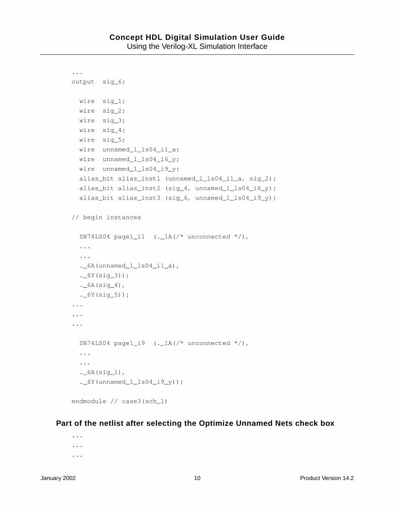
Example 2:
Part of the netlist generated when the Optimize Unnamed Nets is not selected...
January 2002 9 Product Version 14.2
Concept HDL Digital Simulation User GuideUsing the Verilog-XL Simulation Interface
...
output sig_6;
wire sig_1;
wire sig_2;
wire sig_3;
wire sig_4;
wire sig_5;
wire unnamed_1_ls04_i1_a;
wire unnamed_1_ls04_i6_y;
wire unnamed_1_ls04_i9_y;
alias_bit alias_inst1 (unnamed_1_ls04_i1_a, sig_2);
alias_bit alias_inst2 (sig_4, unnamed_1_ls04_i6_y);
alias_bit alias_inst3 (sig_6, unnamed_1_ls04_i9_y);
// begin instances
SN74LS04 page1_i1 (._1A(/* unconnected */),
...
...
._6A(unnamed_1_ls04_i1_a),
._6Y(sig_3));
._6A(sig_4),
._6Y(sig_5));
...
...
...
SN74LS04 page1_i9 (._1A(/* unconnected */),
...
...
._6A(sig_1),
._6Y(unnamed_1_ls04_i9_y));
endmodule // case3(sch_1)
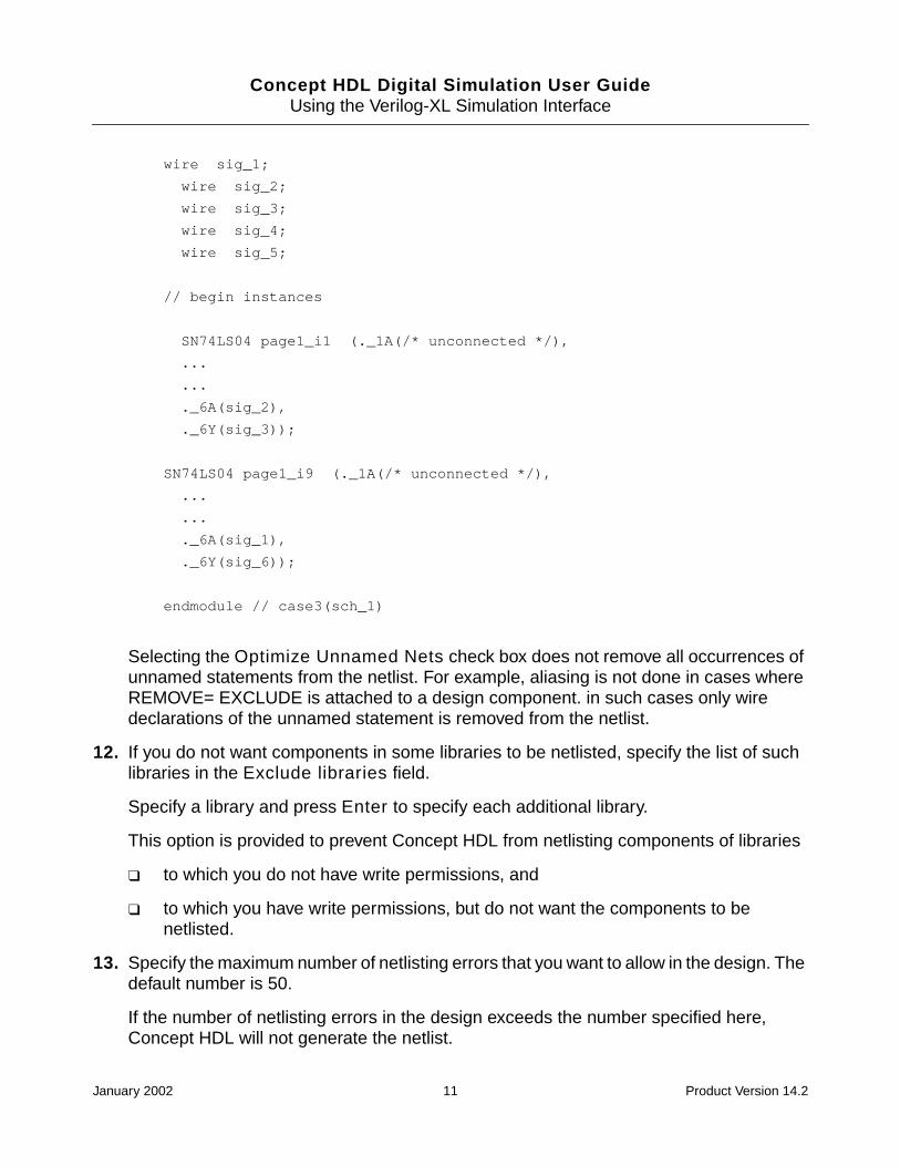
Part of the netlist after selecting the Optimize Unnamed Nets check box...
...
...
January 2002 10 Product Version 14.2
Concept HDL Digital Simulation User GuideUsing the Verilog-XL Simulation Interface
wire sig_1;
wire sig_2;
wire sig_3;
wire sig_4;
wire sig_5;
// begin instances
SN74LS04 page1_i1 (._1A(/* unconnected */),
...
...
._6A(sig_2),
._6Y(sig_3));
SN74LS04 page1_i9 (._1A(/* unconnected */),
...
...
._6A(sig_1),
._6Y(sig_6));
endmodule // case3(sch_1)
Selecting the Optimize Unnamed Nets check box does not remove all occurrences ofunnamed statements from the netlist. For example, aliasing is not done in cases whereREMOVE= EXCLUDE is attached to a design component. in such cases only wiredeclarations of the unnamed statement is removed from the netlist.
12. If you do not want components in some libraries to be netlisted, specify the list of suchlibraries in the Exclude libraries field.
Specify a library and press Enter to specify each additional library.
This option is provided to prevent Concept HDL from netlisting components of libraries
❑ to which you do not have write permissions, and
❑ to which you have write permissions, but do not want the components to benetlisted.
13. Specify the maximum number of netlisting errors that you want to allow in the design. Thedefault number is 50.
If the number of netlisting errors in the design exceeds the number specified here,Concept HDL will not generate the netlist.
January 2002 11 Product Version 14.2

Concept HDL Digital Simulation User GuideUsing the Verilog-XL Simulation Interface
14. Specify the time scale directive for the Verilog module of the schematic in the TimeScale field. The default value is 1ns/1ns.
15. Specify the default logic type for all nets in the design. You can use any legal Verilog nettype, such as WIRE, WAND, and WOR. The default value is WIRE. For more information onVerilog logic types for nets, see the Concept HDL User Guide.
Note: The specified net type applies to all drawings in the design. You can override thenet type for individual drawings by using the VLOG_NET_TYPE property on aVERILOG_DECS symbol.
16. Specify the signal names for the Verilog net type Supply 0.
17. Specify the signal names for the Verilog net type Supply 1.
18. Click OK to save the settings.
Specifying Verilog-XL Simulation Options
1. Select the Simulation tab in the Verilog-XL setup dialog box.
2. Specify the path to the Verilog-XL executable you want to use or click Browse to selectthe Verilog executable.
The default Verilog-XL executable is located in the Cadence installation hierarchy at<your_install_dir>/tools/verilog/bin/verilog.exe.
Note: You can use environment variables to specify the location of your Verilog-XLexecutable. You must add <your_Verilog-XL_install_dir>/tools/lib to thepath.
Example:
If you have an environment variable ENV_VAR set to /usr/user1/cds, and the Verilog-XL executable is located at /usr/user1/cds/verilog.exe, you can use$ENV_VAR/verilog.exe in the field for the Verilog executable.
If you want to switch to /usr/user2/foo/verilog.exe, you should set the ENV_VARenvironment variable to /usr/user2/foo.
3. Set the Delay Mode as Path, Unit, Distributed, Zero, or None.
4. Set the Delay Type as Minimum, Typical, or Maximum.
5. Select the Start SimVision check box to start Verilog-XL in the Affirma SimVisionanalysis environment. For more information, see the Affirma SimVision AnalysisEnvironment User Guide.
January 2002 12 Product Version 14.2

Concept HDL Digital Simulation User GuideUsing the Verilog-XL Simulation Interface
6. Select the Enter Interactive Mode check box to start Verilog-XL in the interactive mode.When you choose this option, Verilog-XL is stopped at time 0 for you to specify thestimulus.
7. Select the Uppercase Identifiers check box if you want Verilog-XL to convert alllowercase identifiers in the netlist such as module names, signal names and instancenames to uppercase.
8. Select the Compile Only check box to stop Verilog-XL after the design is compiled.
9. Specify the path to a Verilog command file.
10. Specify additional command-line options that are not defined in the Verilog command file.
11. Click OK to save the settings.
Specifying Verilog-XL Libraries
1. Select the Library tab in the Verilog-XL setup dialog box.
2. Specify the extensions of Verilog model library file names that Verilog-XL has to searchfor in the Library Extensions field. Type +.<file_extension> to add a fileextension. For example, to add a file extension .vxl, type +.vxl.
If you have specified a directory containing Verilog model libraries, Verilog-XL searchesfor only the model library files in the directory that have the specified extension. Forexample, if you have specified the file extension .vxl, Verilog-XL searches for all files inthe library directory that have the .vxl extension.
3. From the Pathnames drop-down list, select
❑ Directories, to specify the path to the directories containing Verilog model libraries.
OR
❑ Files, to specify the path to Verilog model libraries.
4. Click
❑ to add the path to an element (file or directory). Enter the path to the elementor click the browse button to select the element. See also Using thevlog_model_path.txt file to specify Verilog model libraries on page 14.
You can use environment variables to specify the location of library directories andlibrary files.
Example
January 2002 13 Product Version 14.2

Concept HDL Digital Simulation User GuideUsing the Verilog-XL Simulation Interface
If you have installed one release of a Verilog model library from a third party vendor,and now you want to switch to a new release or to a different installation, you neednot specify the absolute path to the model library. You can specify the librarydirectories in terms of environment variables like $LMC_HOME/special/cds/verilog/swift. When you set the LMC_HOME variable to a different location, thelibrary directory will get modified accordingly.
❑ to delete the selected element
❑ to move the selected element one level up. You may click to move theselected element one level down. The order in which the elements are listeddetermines the search order for Verilog modules in the design. When Verilog-XLfinds a model in an earlier library, it stops looking for the same model in subsequentlibraries.
Example
Suppose you have a model TTL00 in two libraries, lib_a and lib_b. If you wantto use the TTL00 from lib_a, you should move lib_a above lib_b in the list oflibraries.
5. Click OK to save the settings.
Using the vlog_model_path.txt file to specify Verilog model libraries
You can also use the vlog_model_path.txt file to specify the Verilog model libraries. Thelibraries included in this file are displayed in the Library tab. You can place thevlog_model_path.txt file in the project directory or in a Concept HDL component library.
■ In the vlog_model_path.txt file located in the project directory, you can specify thepaths to all the Verilog model libraries required for your design, irrespective of the designlibraries you are using.
■ In the vlog_model_path.txt file located in a Concept HDL component library, youcan specify the paths to all the Verilog models required by the components in the library.This is useful when you are using local libraries and third-party Concept HDL libraries,such as Xilinx libraries.
Note: In each of the Cadence Concept HDL libraries, the path to the Verilog models andthe UDPs are specified in the vlog_model_path.txt file. For example, thevlog_model_path.txt file located at your_install_dir/share/library/lsttl gives the path to the Verilog model libraries for the components in the lsttllibrary as below:
../../../veriloglib/verilogTTL/74LSTTL
../../../veriloglib/verilogUdps
January 2002 14 Product Version 14.2

Concept HDL Digital Simulation User GuideUsing the Verilog-XL Simulation Interface
If your design uses Cadence Reference libraries, the required Verilog model libraries areautomatically included in the Verilog command file. The libraries thus automaticallyincluded are not displayed in the Libraries tab.
You can use environment variables in the vlog_model_path.txt file to specify thelibraries. You can use absolute or relative paths.
Example
Suppose you have two libraries lsttl and memory. You can set the environment variable to$ENV_VAR to your_install_dir/veriloglib and enter the paths to the Verilog modellibraries required in the vlog_model_path.txt file as
$ENV_VAR/verilogMEMORY
$ENV_VAR/verilogTTL
The directories specified in the vlog_model_path.txt file will be passed to Verilog-XLwith the -y option.
The vlog_model_path.txt file is searched for in the order specified in the setup.locfile located at your_install_dir/share/cdssetup/. The search terminates whenthe first vlog_model_path.txt is found.
Providing a Testfixture for Verilog Simulation
You can simulate your design either by instantiating the top level design in a testfixturemodule, or by including a test vector generator in the schematic. You can provide thetestfixture by using any of the following methods:
■ Generating a Testbench
You can generate a testbench that instantiates the top level module with a port list. Allthe interface signals in your design are listed in the port list of the generated testbench.You have to regenerate the testbench if the port list changes.
You can specify the signal activity on the interface signals by editing the testbenchmodule or by including a stimulus file that provides this information using a ‘includestatement in the testbench file.
■ Including a Testbench
For subsequent runs of the simulation process, you can include the testbench generatedearlier. You have to regenerate the testbench if the port list changes.
You can specify the signal activity on the interface signals in the design by including astimulus file that provides this information using a ‘include statement.
January 2002 15 Product Version 14.2

Concept HDL Digital Simulation User GuideUsing the Verilog-XL Simulation Interface
If you do not want to instantiate your design in another module but have a stimulus actingdirectly on the interface signals, you can use the Include Testbench option. In this case,you have to specify the stimulus directly using the canonical names for the signals of yourinterest.
■ Using Only a Stimulus File
You can use only a stimulus file when the design is self-stimulating or when the stimulusis at the same level as the design under test.
You can record the simulation history by opening an SHM database and setting probes onsignals of your interest.
A typical testfixture file is shown below. The name of the top level design is top_design.topinst instantiates the top design specifying the required port names. The stimulus file(stimulus.v) is included into this testfixture using the ‘include compiler directive. Thisallows you to modify the stimulus file without changing the testfixture file.
‘timescale 1ns/1ns
module test;
reg[7:0] ADDR;
wire[2:0] OUT;
reg CLOCK;
wire RESET;
top_design topinst (ADDR,CLOCK,RESET,OUT);
initial
begin
$shm_open("file.shm");
$shm_probe(topinst.page1_i2);
end
`ifdef Verilog
`include "stimulus.v"
`endif
endmodule
You can specify your stimulus in terms of always and initial blocks in Verilog. You canuse Verilog canonical names to specify the signals. A sample Verilog stimulus file is givenbelow:
always
#150 CLOCK = ~CLOCK;
initial
begin
January 2002 16 Product Version 14.2

Concept HDL Digital Simulation User GuideUsing the Verilog-XL Simulation Interface
CLOCK = 1;
$deposit(RESET , 1'b0);
# 100;
$deposit(RESET, 1);
# 20000;
$finish;
end
Generating a Testbench
Before you can generate a testbench, ensure that the simulation netlist, /sim_sch_1/verilog.v has been generated. This is must because the simulation netlist in thesim_sch_1 view is used for testbench generation. To generate a testbench, do the following:
1. Select the Stimulus tab in the Verilog-XL setup dialog box.
2. Select the Generate Testbench option.
3. Specify the path to the stimulus file (which specifies the signal activity on the interfacesignals) in the Stimulus File field, or click Browse to select the stimulus file.
The specified stimulus file will be included through the ‘include directive in thetestfixture module.
4. Specify the name of the design instance in the Design Instance field. The default valueis top.
5. Enter the time scale directive for the testbench module in the Time Scale field.
6. Click Generate to generate the testbench module.
The testbench file verilog.v is created in the following directory:
<project_directory>/worklib/testfixture/<design_name>_sim_sch_1
7. Click OK to save the settings.
Including a Testbench
To include a testbench to provide a stimulus to your design during simulation, do the following:
1. Select the Stimulus tab in the Verilog-XL setup dialog box.
2. Select the Include Testbench option.
3. Specify the path to the testbench module in the Testbench File field or click Browse toselect the testbench module.
January 2002 17 Product Version 14.2

Concept HDL Digital Simulation User GuideUsing the Verilog-XL Simulation Interface
4. Click OK to save the settings.
Note: If you have a testbench, you must select the Include Testbench option to performcross-probing between Concept HDL and Verilog-XL. If you select the Stimulus File Onlyoption, you cannot perform cross-probing between Concept HDL and Verilog-XL.
Using Only a Stimulus File
You can use only a stimulus file when the design is self-stimulating or when the stimulus is atthe same level as the design under test.
To use only a stimulus file, do the following:
1. Select the Stimulus tab in the Verilog-XL setup dialog box.
2. Select the Stimulus File Only option.
3. Specify the path to the stimulus file in the Stimulus File field, or click Browse to selectthe stimulus file.
4. Click OK to save the settings.
Note: If you have a testbench, cross probing between Concept HDL and Verilog-XL will notwork if you select the Stimulus File Only option. To enable cross probing, you must selectthe Include Testbench option.
Specifying Allegro SDF Annotation Options
You can specify the options for the SDF Annotator to annotate timing data to the Verilog-XLsimulator. The SDF Annotator reads the specified Allegro standard delay format (SDF) fileand annotates the timing data to the simulator. The Allegro SDF file is generated using theAllegro a2sdf wire delay extract utility. This file contains compensated switch and settledelays and rise and fall propagation delays. For more information on the SDF Annotator andSDF files, see the SDF Annotator Guide.
1. Select the Allegro SDF tab in the Verilog-XL setup dialog box.
2. Select the Perform SDF Annotation check box if you want to perform SDF annotation.
3. Specify the path to the Allegro SDF file or click Browse to select the SDF file.
The SDF Annotator reads this SDF file. This file does not appear on the Verilogcommand line.
Note: You should not specify FPGA/CPLD SDF files in this field.
January 2002 18 Product Version 14.2
Concept HDL Digital Simulation User GuideUsing the Verilog-XL Simulation Interface
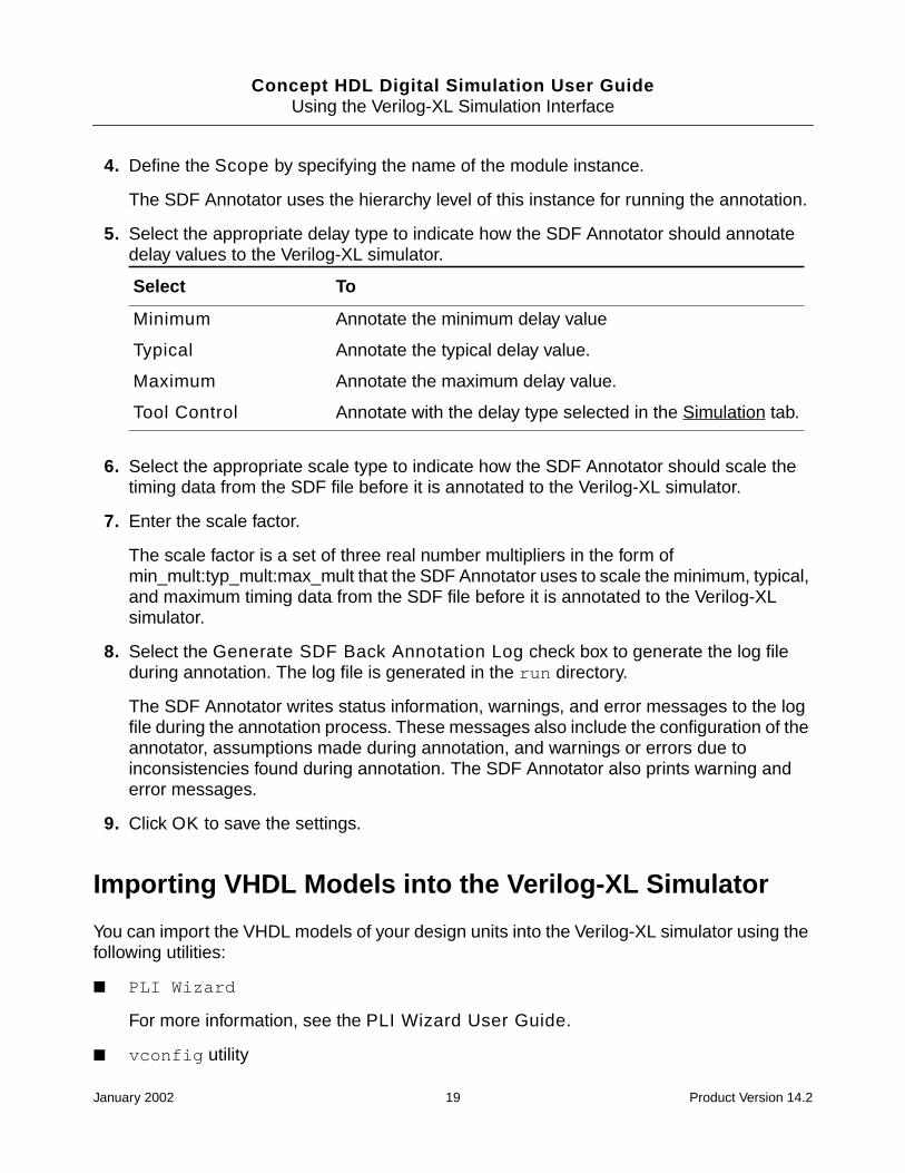
4. Define the Scope by specifying the name of the module instance.
The SDF Annotator uses the hierarchy level of this instance for running the annotation.
5. Select the appropriate delay type to indicate how the SDF Annotator should annotatedelay values to the Verilog-XL simulator.
6. Select the appropriate scale type to indicate how the SDF Annotator should scale thetiming data from the SDF file before it is annotated to the Verilog-XL simulator.
7. Enter the scale factor.
The scale factor is a set of three real number multipliers in the form ofmin_mult:typ_mult:max_mult that the SDF Annotator uses to scale the minimum, typical,and maximum timing data from the SDF file before it is annotated to the Verilog-XLsimulator.
8. Select the Generate SDF Back Annotation Log check box to generate the log fileduring annotation. The log file is generated in the run directory.
The SDF Annotator writes status information, warnings, and error messages to the logfile during the annotation process. These messages also include the configuration of theannotator, assumptions made during annotation, and warnings or errors due toinconsistencies found during annotation. The SDF Annotator also prints warning anderror messages.
9. Click OK to save the settings.
Importing VHDL Models into the Verilog-XL Simulator
You can import the VHDL models of your design units into the Verilog-XL simulator using thefollowing utilities:
■ PLI Wizard
For more information, see the PLI Wizard User Guide.
■ vconfig utility
Select To
Minimum Annotate the minimum delay value
Typical Annotate the typical delay value.
Maximum Annotate the maximum delay value.
Tool Control Annotate with the delay type selected in the Simulation tab.
January 2002 19 Product Version 14.2

Concept HDL Digital Simulation User GuideUsing the Verilog-XL Simulation Interface
For more information, see “Setting Up to Import VHDL Models Into Verilog-XLDesigns,” in the Verilog-XL Configuration Guide.
VHDL Cosimulation
The simulation of VHDL model in a Verilog environment is accomplished by VHDLcosimulation. Verilog-XL invokes Leapfrog in the slave mode when it encounters VHDLmodels that are incorporated in Verilog HDL design descriptions. For more information, seeChapter 11, “VHDL Cosimulation,” in the Verilog-XL User Guide.
Providing Instance-Based Binding Support
Model Binding with Netlist
Concept HDL writes the schematic information and a Verilog netlist when you save aschematic. The Verilog netlist is the equivalent HDL description for the schematic. The Verilognetlist file verilog.v is created in the schematic view. This netlist contains the variousinstances in the design, their interfaces, and connectivity. The instantiation uses the
January 2002 20 Product Version 14.2
Concept HDL Digital Simulation User GuideUsing the Verilog-XL Simulation Interface
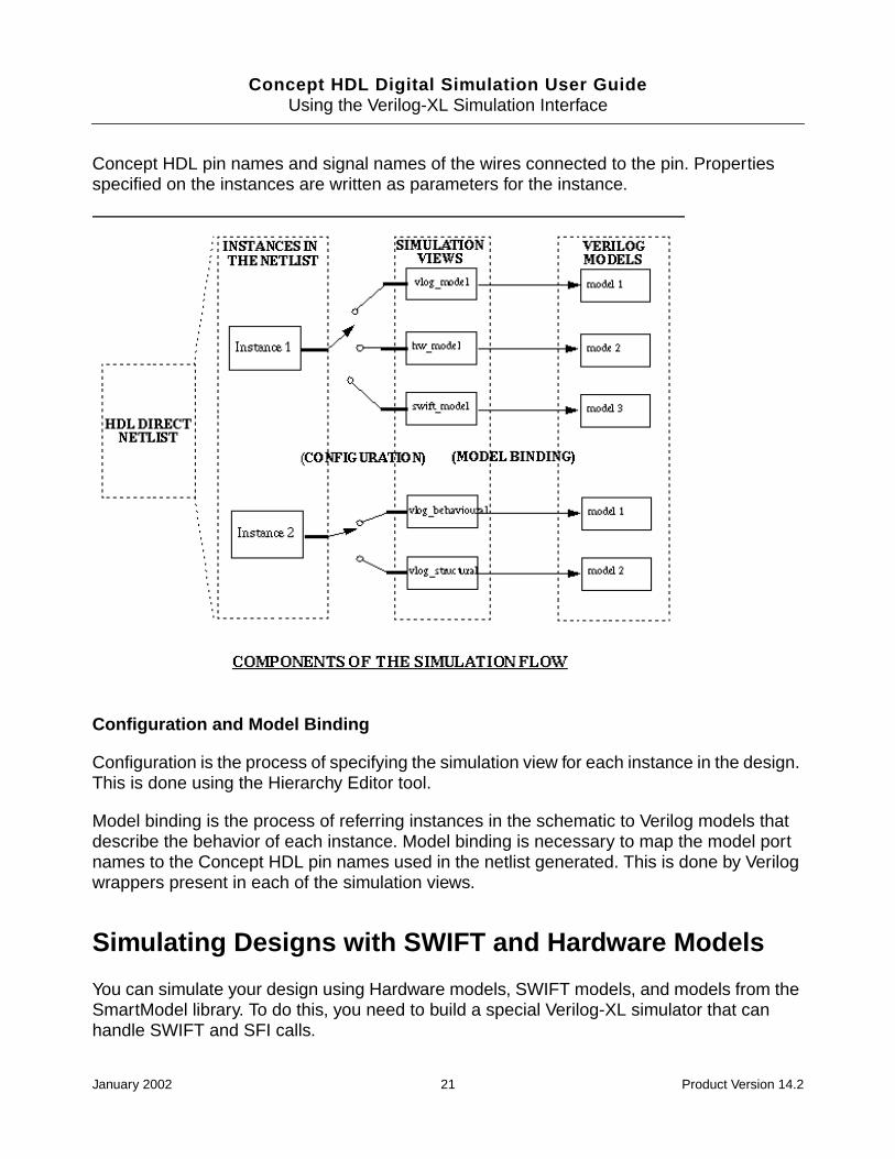
Concept HDL pin names and signal names of the wires connected to the pin. Propertiesspecified on the instances are written as parameters for the instance.
Configuration and Model Binding
Configuration is the process of specifying the simulation view for each instance in the design.This is done using the Hierarchy Editor tool.
Model binding is the process of referring instances in the schematic to Verilog models thatdescribe the behavior of each instance. Model binding is necessary to map the model portnames to the Concept HDL pin names used in the netlist generated. This is done by Verilogwrappers present in each of the simulation views.
Simulating Designs with SWIFT and Hardware Models
You can simulate your design using Hardware models, SWIFT models, and models from theSmartModel library. To do this, you need to build a special Verilog-XL simulator that canhandle SWIFT and SFI calls.
January 2002 21 Product Version 14.2

Concept HDL Digital Simulation User GuideUsing the Verilog-XL Simulation Interface
You can use the following scripts to build the Verilog-XL simulator:
■ The vconfig script (located at <your_VerilogXL_install_dir>/tools/verilog/bin)provided by Cadence. For more information on running the vconfig script, see theVerilog-XL Configuration Guide.
■ The lmc_vconfig script (located at <synopsys_install_dir>/bin) provided bySynopsys to build a Verilog-XL executable that is compliant with the Synopsys LMTVinterface. The lmc_vconfig calls the vconfig script.
The script you should use depends on the following:
■ If you are using Hardware models in your design and none of the SWIFT models, usethe vconfig script to build your Verilog-XL simulator with SFI support.
For using Hardware models, you need to use the Verilog file having the SFI call for modelinstantiation.
■ If you want to use SWIFT models as well as Hardware models, you should use thelmc_vconfig script to build the Verilog-XL simulator.
❑ For using SWIFT models, you should include the models in your LMC installation.
❑ For using Hardware models, you need to use the Verilog file having the SFI call formodel instantiation.
■ If you want to use models from the SmartModel library in your design, you must use thelmc_vconfig script to build the Verilog-XL simulator.
To build the special Verilog-XL simulator using the lmc_vconfig script
1. Modify the file veriuser.c located at <your_VerilogXL_install_dir>/tools/verilog/src for building a Verilog simulator with SWIFT support.
2. Set up the environment for running lmc_vconfig as below:
❑ setenv LMC_HOME <synopsys_install_dir>
❑ setenv LMC_CDS_VCONFIG <your_Verilog-XL_install_dir>/tools/verilog/bin
3. Verify the path to the veriuser.c file <your_Verilog-XL_install_dir>/tools/verilog/src.
4. Run the lmc_vconfig script from the location where you want to create cr_vlog. Thelmc_vconfig script copies the veriuser.c file to the current directory; edits it toinclude files needed for the LMTV interface; calls the vconfig script, and then edits theresulting cr_vlog script to add the needed libraries and switches. For more information,see Running lmc_vconfig.
January 2002 22 Product Version 14.2
Concept HDL Digital Simulation User GuideUsing the Verilog-XL Simulation Interface
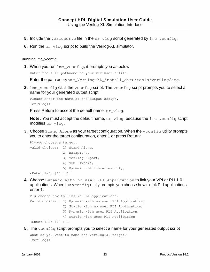
5. Include the veriuser.c file in the cr_vlog script generated by lmc_vconfig.
6. Run the cr_vlog script to build the Verilog-XL simulator.
Running lmc_vconfig
1. When you run lmc_vconfig, it prompts you as below:
Enter the full pathname to your veriuser.c file.
Enter the path as <your_Verilog-XL_install_dir>/tools/verilog/src.
2. lmc_vconfig calls the vconfig script. The vconfig script prompts you to select aname for your generated output script
Please enter the name of the output script.
[cr_vlog]:
Press Return to accept the default name, cr_vlog.
Note: You must accept the default name, cr_vlog, because the lmc_vconfig scriptmodifies cr_vlog.
3. Choose Stand Alone as your target configuration. When the vconfig utility promptsyou to enter the target configuration, enter 1 or press Return:
Please choose a target.
valid choices: 1) Stand Alone,
2) Backplane,
3) Verilog Export,
4) VHDL Import,
5) Dynamic PLI libraries only,
<Enter 1-5> [1] : 1
4. Choose Dynamic with no user PLI Application to link your VPI or PLI 1.0applications. When the vconfig utility prompts you choose how to link PLI applications,enter 1:
Pls choose how to link in PLI applications.
Valid choices: 1) Dynamic with no user PLI Application,
2) Static with no user PLI Application,
3) Dynamic with user PLI Application,
4) Static with user PLI Application
<Enter 1-4> [1] : 1
5. The vconfig script prompts you to select a name for your generated output script
What do you want to name the Verilog-XL target?
[verilog]:
January 2002 23 Product Version 14.2

Concept HDL Digital Simulation User GuideUsing the Verilog-XL Simulation Interface
Press Return to accept the default name, verilog.
6. Enter y for the following vconfig prompt:
Do you want to compile for the Verilog-XL SimVision environment?
<Enter y/n/CR> [y]: y
7. The Synopsys LMTV interface replaces the Cadence LAI interface. Therefore, to useLMTV and not the Cadence LAI interface, you must enter no at the following two promptsissued by the vconfig script:
Do you want to compile for the New GRWAVES interface?
<Enter y/n/CR> [y] : n
Do you want to include STATIC LOGIC AUTOMATION
models in this Verilog-XL executable ?
<Enter y/n/CR> [n] : n
8. Enter y at the following prompt and specify the directory where the LMC modeler librariesare located. Typically, it will be $LM_DIR/../lib/<platform>:
Do you want to include the LMSI HARDWARE MODELER interface software in thisVerilog-XL executable?
<Enter y/n/CR> [n]: y
Please enter the path name to the directory containing your LMC modeler libraryfiles (*sfi.a).
The default presented in [] reflects what was found using the LM_DIR environmentvariable [] : $LM_DIR/../lib/<platform>
When vconfig completes successfully, it displays the following message:
***SUCCESSFUL COMPLETION OF VCONFIG***
***EXECUTE THE SCRIPT: cr_vlog TO BUILD: Stand Alone Verilog-XL
9. Edit the cr_vlog script generated by the lmc_vconfig script and add the following lineto it to compile the modified version of the veriuser.c along with the LMC library.
./veriuser.c -I<$LMC_HOME>/include \
10. Execute cr_vlog to build the special Verilog simulator.
Note: Verify that you have a C compiler and the license before executing cr_vlog to build theVerilog simulator.
Running the Verilog-XL Simulator
To run the Verilog-XL simulator, you have to access the Verilog-XL Start Simulator dialog box.You can access the Verilog-XL Start Simulator dialog box in any of the following ways:
■ From Project Manager or Concept HDL, choose Tools > Simulate.
January 2002 24 Product Version 14.2

Concept HDL Digital Simulation User GuideUsing the Verilog-XL Simulation Interface
■ Enter the following command in a UNIX terminal or the DOS command line:
lwbhdl -proj <projectname.cpm>
The Verilog-XL Start Simulator dialog box appears.
To run the Verilog-XL simulator
1. Select the configuration view.
2. Specify the path to the run directory or click Browse to select the directory.
By default, a run directory sim1 is created in the configuration view you selected.
3. Click Run.
The Simulation Progress Status window appears displaying the progress of thesimulation process.
4. Click Details to view the details of the simulation process.
During the simulation process, the design is netlisted and compiled and SDF Annotationis performed. Once the simulation process is complete, the Verilog-XL simulator isinvoked.
Cross Probing between Concept HDL and Verilog-XL
Cross probing is an effective way of debugging a design. Through cross probing, you canselect a component or net in Concept HDL and view its value in Verilog-XL. You can simulatethe netlist by specifying the stimulus vectors in Verilog-XL.
To select components or nets in Concept HDL and view their value in Verilog-XL,
1. In Concept HDL, click the component instance or the signal.
The component or the signal gets selected.
2. In Verilog-XL, do one of the following:
❑ Click Show Value.
Verilog-XL displays the value of the selected cell or net.
❑ Click Wave Trace.
Signalscan Waves displays the selected cell or net value in a wave form.
January 2002 25 Product Version 14.2

Concept HDL Digital Simulation User GuideUsing the Verilog-XL Simulation Interface
You can select multiple objects in Concept HDL and highlight all of them together in Verilog-XL by creating a group in Concept HDL. This feature is useful when you want to display anumber of signals in Signalscan Waves by selecting the signals from Concept HDL.
To cross probe multiple objects,
1. In Concept HDL, create a group by choosing Group > Create > By Rectangle.
For more information, see Working with Groups in the Concept HDL User Guide.
2. Select the objects you want to cross probe.
3. Press Esc, or type ; in the Concept HDL Console to complete the formation of the group.
4. With the cursor in the Concept HDL window,
❑ In UNIX, click the middle mouse button.
❑ In Windows NT, press Ctrl and click the left mouse button.
5. Switch to Verilog-XL to look at the highlighted objects. If you are in a different scope thanwhat Concept HDL is in, you may not see the objects highlighted. You can set the scopeappropriately to see the objects highlighted. However, it is not necessary for you tochange to the right scope to perform any of the display or debug operations.
6. Click the SimWave button to bring up Signalscan Waves with the selected signals.
Note: Cross-probing will not work if you have a testbench and you select the Stimulus FileOnly option in the Stimulus (Verilog) tab of the Verilog-XL setup dialog box. If you have atestbench, select the Include Testbench option in the Stimulus (Verilog) tab of the Verilog-XL setup dialog box. The Stimulus File Only option should be selected only when thedesign is self-stimulating or when the stimulus is at the same level as the design under test.For more information, see Providing a Testfixture for Verilog Simulation on page 15.
In Verilog, you can have multiple highest level modules. You can have the design under testas one top level module and the stimulus as the other top level module. This allows you tospecify the stimulus directly accessing the nets and ports in the design using Verilogcanonical paths. In this case, the cross-probing utility translates the Concept HDL names ofthe selected objects to their respective Verilog canonical names.
If you have selected the Include Testbench option in the Stimulus (Verilog) tab of theVerilog-XL setup dialog box, this module instantiates the design under test. The testbenchfile is analyzed to determine the instance name used. Since the Concept HDL designhierarchy is one level lower than the Verilog design hierarchy (due to the testbench), theinstance name is prefixed to the Concept HDL object name to get the Verilog canonical namefor the selected object.
January 2002 26 Product Version 14.2

Concept HDL Digital Simulation User Guide
3Using the NC Verilog Simulation Interface
You can simulate your Verilog designs from Concept HDL using the NC Verilog simulator.Performing digital simulation using the NC Verilog simulator involves the following tasks:
1. Selecting the NC Verilog Simulator
2. Setting Up the NC Verilog Simulation Interface
3. Creating a new design configuration or modifying an existing design configuration usingthe Hierarchy Editor tool. For more information, see Appendix C, “SimulationConfigurations.”
4. Running a simulation on your design using the specified design configuration. Thedesign is netlisted and compiled, and the NC Verilog simulator is invoked. For moreinformation, see Running the NC Verilog Simulator.
5. Simulating your design using the simulator
6. Browsing waveforms and debugging your design. You can cross probe betweenConcept HDL and NC Verilog to quickly debug your design.
Selecting the NC Verilog Simulator
To use the NC Verilog simulator for simulating a design, you have to select the NC Verilogsimulator. To do this
1. Start Project Manager.
2. Open the project.
3. Choose Tools > Setup.
The Project Setup window appears.
4. Select the Tools tab.
5. Click Simulation Setup.
January 2002 27 Product Version 14.2

Concept HDL Digital Simulation User GuideUsing the NC Verilog Simulation Interface
The Choose Simulator dialog box appears.
6. Select the NC Verilog option and click OK.
Setting Up the NC Verilog Simulation Interface
You can set up the following for running the NC Verilog simulator:
■ Specify netlisting options.
For more information, see Specifying NC Verilog Netlisting Options on page 29.
■ Specify simulation options.
For more information, see Specifying NC Verilog Simulation Options on page 31.
■ Provide testfixture for Verilog simulation.
For more information, see Providing a Testfixture for Verilog Simulation on page 32.
■ Specify options for performing SDF annotation.
For more information, see Specifying SDF Annotation Options on page 34.
To specify the NC Verilog options you must access the NC Verilog setup dialog box. You canaccess the NC Verilog setup dialog box in the following ways:
■ From the Project Setup window
a. In Project Manager, choose Tools > Setup.
The Project Setup window appears.
b. Select the Tools tab.
c. Click Simulation Setup.
The Choose Simulator dialog box appears.
d. Select the NC Verilog option, and click Setup.
The NC Verilog setup dialog box appears.
■ From Project Manager or Concept HDL
a. Choose Tools > Simulate.
The NC Verilog Start Simulator dialog box appears.
January 2002 28 Product Version 14.2
Concept HDL Digital Simulation User GuideUsing the NC Verilog Simulation Interface
b. Click Setup.
The NC Verilog setup dialog box appears.
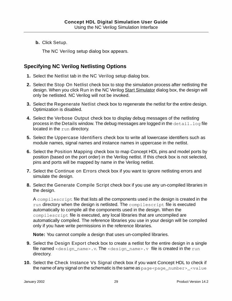
Specifying NC Verilog Netlisting Options
1. Select the Netlist tab in the NC Verilog setup dialog box.
2. Select the Stop On Netlist check box to stop the simulation process after netlisting thedesign. When you click Run in the NC Verilog Start Simulator dialog box, the design willonly be netlisted. NC Verilog will not be invoked.
3. Select the Regenerate Netlist check box to regenerate the netlist for the entire design.Optimization is disabled.
4. Select the Verbose Output check box to display debug messages of the netlistingprocess in the Details window. The debug messages are logged in the detail.log filelocated in the run directory.
5. Select the Uppercase Identifiers check box to write all lowercase identifiers such asmodule names, signal names and instance names in uppercase in the netlist.
6. Select the Position Mapping check box to map Concept HDL pins and model ports byposition (based on the port order) in the Verilog netlist. If this check box is not selected,pins and ports will be mapped by name in the Verilog netlist.
7. Select the Continue on Errors check box if you want to ignore netlisting errors andsimulate the design.
8. Select the Generate Compile Script check box if you use any un-compiled libraries inthe design.
A compilescript file that lists all the components used in the design is created in therun directory when the design is netlisted. The compilescript file is executedautomatically to compile all the components used in the design. When thecompilescript file is executed, any local libraries that are uncompiled areautomatically compiled. The reference libraries you use in your design will be compiledonly if you have write permissions in the reference libraries.
Note: You cannot compile a design that uses un-compiled libraries.
9. Select the Design Export check box to create a netlist for the entire design in a singlefile named <design_name>.v. The <design_name>.v file is created in the rundirectory.
10. Select the Check Instance Vs Signal check box if you want Concept HDL to check ifthe name of any signal on the schematic is the same as page<page_number>_<value
January 2002 29 Product Version 14.2
Concept HDL Digital Simulation User GuideUsing the NC Verilog Simulation Interface
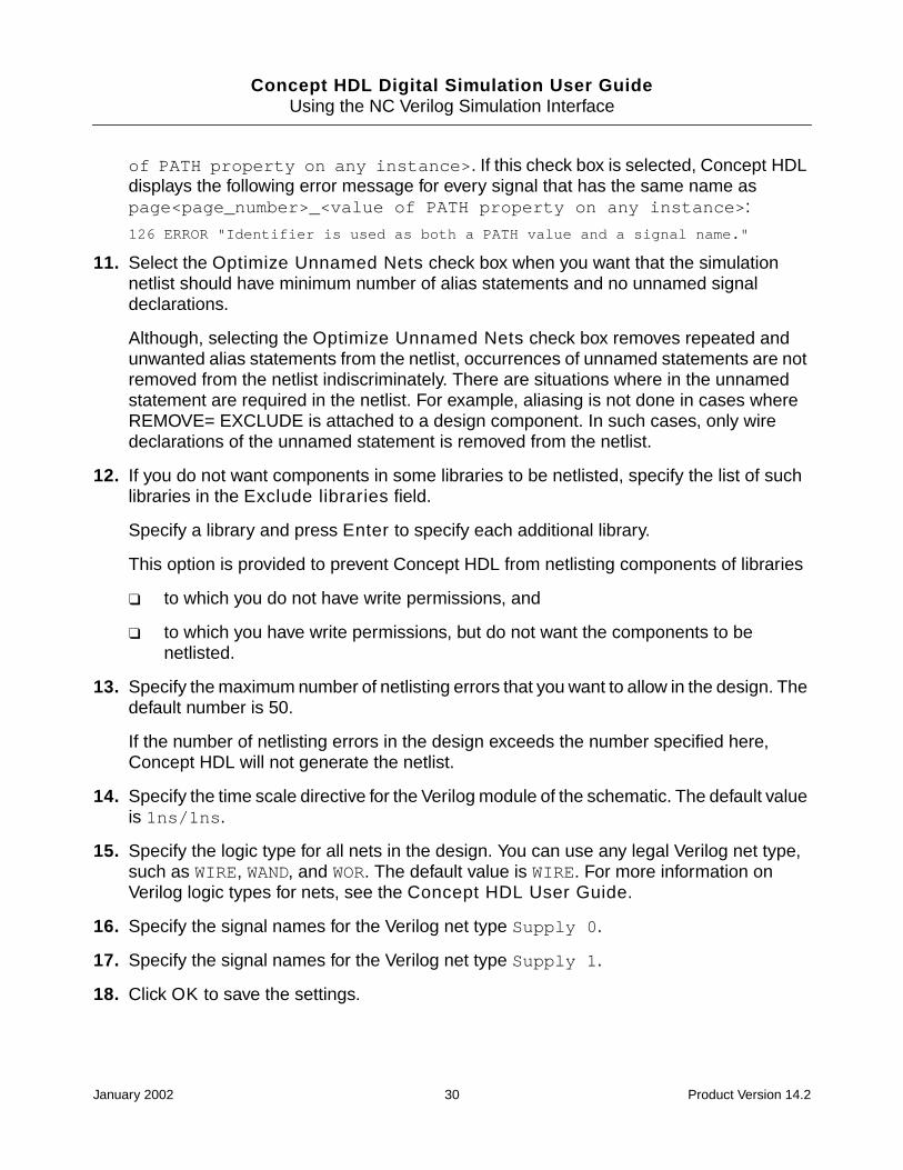
of PATH property on any instance>. If this check box is selected, Concept HDLdisplays the following error message for every signal that has the same name aspage<page_number>_<value of PATH property on any instance>:
126 ERROR "Identifier is used as both a PATH value and a signal name."
11. Select the Optimize Unnamed Nets check box when you want that the simulationnetlist should have minimum number of alias statements and no unnamed signaldeclarations.
Although, selecting the Optimize Unnamed Nets check box removes repeated andunwanted alias statements from the netlist, occurrences of unnamed statements are notremoved from the netlist indiscriminately. There are situations where in the unnamedstatement are required in the netlist. For example, aliasing is not done in cases whereREMOVE= EXCLUDE is attached to a design component. In such cases, only wiredeclarations of the unnamed statement is removed from the netlist.
12. If you do not want components in some libraries to be netlisted, specify the list of suchlibraries in the Exclude libraries field.
Specify a library and press Enter to specify each additional library.
This option is provided to prevent Concept HDL from netlisting components of libraries
❑ to which you do not have write permissions, and
❑ to which you have write permissions, but do not want the components to benetlisted.
13. Specify the maximum number of netlisting errors that you want to allow in the design. Thedefault number is 50.
If the number of netlisting errors in the design exceeds the number specified here,Concept HDL will not generate the netlist.
14. Specify the time scale directive for the Verilog module of the schematic. The default valueis 1ns/1ns.
15. Specify the logic type for all nets in the design. You can use any legal Verilog net type,such as WIRE, WAND, and WOR. The default value is WIRE. For more information onVerilog logic types for nets, see the Concept HDL User Guide.
16. Specify the signal names for the Verilog net type Supply 0.
17. Specify the signal names for the Verilog net type Supply 1.
18. Click OK to save the settings.
January 2002 30 Product Version 14.2

Concept HDL Digital Simulation User GuideUsing the NC Verilog Simulation Interface
Specifying NC Verilog Simulation Options
1. Select the Simulation tab in the NC Verilog setup dialog box.
2. Specify the path to the hdl.var file, or click Browse to select the file.
If you do not specify the path to the hdl.var file, a default hdl.var file will be createdin the run directory.
3. Enter the path to the directory where you want the following log files to be created:
❑ ncvlog.log, which contains the messages logged when the design is compiled.
❑ ncelab.log, which contains the messages logged when the design is elaborated.
❑ ncsim.log, which contains the messages logged when the design is simulated.
By default the log files are created in the run directory.
4. Select the Compile check box if you want to compile the design every time you run thesimulation.
Enter additional command-line options for ncvlog in the Cmd Options field.
5. Select the Elaborate check box if you want to elaborate the design every time you runthe simulation.
Enter additional command-line options for ncelab in the Cmd Options field.
6. Select the Simulate check box if you want to simulate the design in the NC Verilogsimulator every time you run the simulation. The simulator will not be invoked if this checkbox is not selected.
Enter additional command-line options for ncsim in the Cmd Options field.
7. Select the Start SimVision check box to start NC Verilog in the Affirma SimVisionanalysis environment. For more information, see the Affirma SimVision AnalysisEnvironment User Guide.
8. Select the Enter Interactive Mode check box to start NC Verilog in the interactivemode. When you choose this option, NC Verilog is stopped at time 0 for you to specifythe stimulus.
9. Click OK to save the settings.
January 2002 31 Product Version 14.2

Concept HDL Digital Simulation User GuideUsing the NC Verilog Simulation Interface
Providing a Testfixture for Verilog Simulation
You can simulate your design either by instantiating the top level design in a testfixturemodule, or by including a test vector generator in the schematic. You can provide thetestfixture by using any of the following methods:
■ Generating a Testbench
You can generate a testbench that instantiates the top level module with a port list. Allthe interface signals in your design are listed in the port list of the generated testbench.You have to regenerate the testbench if the port list changes.
You can specify the signal activity on the interface signals by editing the testbenchmodule or by including a stimulus file that provides this information using a ‘includestatement.
■ Including a Testbench
For subsequent runs of the simulation process, you can include the testbench generatedearlier. You have to regenerate the testbench if the port list changes.
You can specify the signal activity on the interface signals in the design by including astimulus file that provides this information using a ‘include statement.
If you do not want to instantiate your design in another module but have a stimulus actingdirectly on the interface signals, you can use the Include Testbench option. In this case,you have to specify the stimulus directly using the canonical names for the signals of yourinterest.
You can record the simulation history by opening an SHM database and setting probes onsignals of your interest.
A typical testfixture file is shown below. The name of the top level design is top_design.topinst instantiates the top design specifying the required port names. The stimulus filestimulus.v is included into this testfixture using the ‘include compiler directive. Thisallows you to modify the stimulus file without changing the testfixture file.
‘timescale 1ns/1ps
module test;
reg[7:0] ADDR;
wire[2:0] OUT;
reg CLOCK;
wire RESET;
top_design topinst (ADDR,CLOCK,RESET,OUT);
initial
begin
January 2002 32 Product Version 14.2
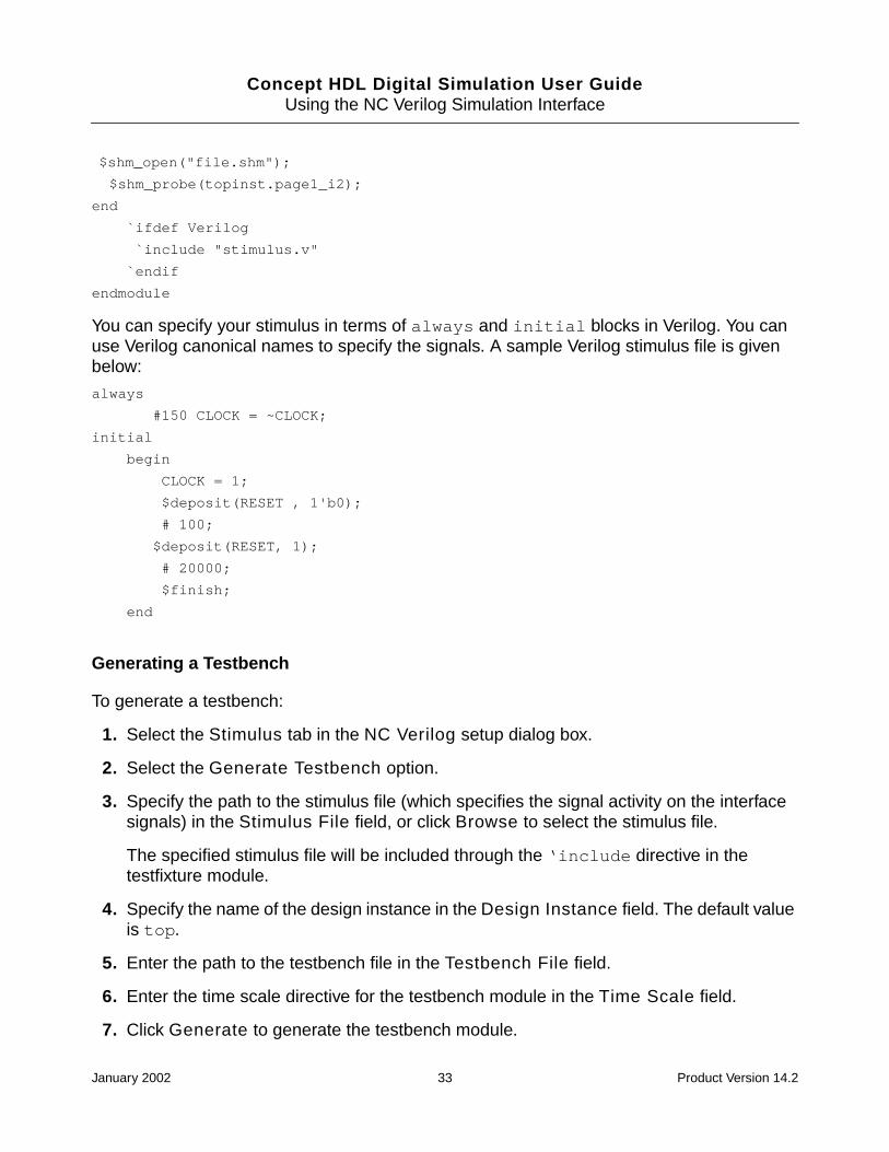
Concept HDL Digital Simulation User GuideUsing the NC Verilog Simulation Interface
$shm_open("file.shm");
$shm_probe(topinst.page1_i2);
end
`ifdef Verilog
`include "stimulus.v"
`endif
endmodule
You can specify your stimulus in terms of always and initial blocks in Verilog. You canuse Verilog canonical names to specify the signals. A sample Verilog stimulus file is givenbelow:
always
#150 CLOCK = ~CLOCK;
initial
begin
CLOCK = 1;
$deposit(RESET , 1'b0);
# 100;
$deposit(RESET, 1);
# 20000;
$finish;
end
Generating a Testbench
To generate a testbench:
1. Select the Stimulus tab in the NC Verilog setup dialog box.
2. Select the Generate Testbench option.
3. Specify the path to the stimulus file (which specifies the signal activity on the interfacesignals) in the Stimulus File field, or click Browse to select the stimulus file.
The specified stimulus file will be included through the ‘include directive in thetestfixture module.
4. Specify the name of the design instance in the Design Instance field. The default valueis top.
5. Enter the path to the testbench file in the Testbench File field.
6. Enter the time scale directive for the testbench module in the Time Scale field.
7. Click Generate to generate the testbench module.
January 2002 33 Product Version 14.2

Concept HDL Digital Simulation User GuideUsing the NC Verilog Simulation Interface
The testbench file verilog.v is created in the following directory:
<project_directory>/worklib/testfixture/<design_name>_sim_sch_1
8. Click OK to save the settings.
Note: Testbench can be generated only if the simulation netlist, /sim_sch_1/verilog.v,is already created. This simulation netlist is required for generating the testbench. Therefore,before generating the testbench, ensure that the simulator should have run at least once sothat the sim_sch_1 view is created.
Including a Testbench
To include a testbench to provide a stimulus to your design during simulation
1. Select the Stimulus tab in the NC Verilog setup dialog box.
2. Select the Include Testbench option.
3. Specify the path to the testbench module in the Testbench File field or click Browse toselect the testbench module.
4. Click OK to save the settings.
Specifying SDF Annotation Options
You can specify the options for the SDF Annotator to annotate timing data to the NC Verilogsimulator. The SDF Annotator reads the specified Allegro standard delay format (SDF) fileand annotates the timing data to the simulator. The Allegro SDF file is generated using theAllegro a2sdf wire delay extract utility. This file contains compensated switch and settledelays and rise and fall propagation delays. For more information on the SDF Annotator andSDF files, see the SDF Annotator Guide.
1. Select the Allegro SDF tab in the NC Verilog setup dialog box.
2. Select the Perform SDF Annotation check box if you want to perform SDF annotation.
3. Specify the path to the Allegro SDF file or click Browse to select the SDF file.
The SDF Annotator reads this SDF file. This file does not appear on the Verilogcommand line.
Note: You should not specify FPGA/CPLD SDF files in this field.
4. Define the Scope by specifying the name of the module instance.
The SDF Annotator uses the hierarchy level of this instance for running the annotation.
January 2002 34 Product Version 14.2

Concept HDL Digital Simulation User GuideUsing the NC Verilog Simulation Interface
5. Select the appropriate delay type to indicate how the SDF Annotator should annotatedelay values to the NC Verilog simulator.
6. Select the appropriate scale type to indicate how the SDF Annotator should scale thetiming data from the SDF file before it is annotated to the NC Verilog simulator.
7. Enter the scale factor.
The scale factor is a set of three real number multipliers in the form ofmin_mult:typ_mult:max_mult that the SDF Annotator uses to scale the minimum, typical,and maximum timing data from the SDF file before it is annotated to the NC Verilogsimulator.
8. Select the Generate SDF Back Annotation Log check box to generate the log fileduring annotation. The log file is generated in the run directory.
The SDF Annotator writes status information, warnings, and error messages to the logfile during the annotation process. These messages also include the configuration of theannotator, assumptions made during annotation, and warnings or errors due toinconsistencies found during annotation. The SDF Annotator also prints warning anderror messages.
9. Click OK to save the settings.
For more information on the SDF Annotator and SDF files, see the SDF Annotator Guide.
Importing VHDL Models into the NC Verilog Simulator
You can import the VHDL models of your design units into the NC Verilog simulator. For moreinformation, see Chapter 10, “Mixed Verilog/VHDL Simulation,” in the Affirma NC VerilogSimulator Help.
Select To
Minimum Annotate the minimum delay value.
Typical Annotate the typical delay value.
Maximum Annotate the maximum delay value.
Tool Control Annotate with the delay type selected in the NC Verilog:Simulation tab.
January 2002 35 Product Version 14.2

Concept HDL Digital Simulation User GuideUsing the NC Verilog Simulation Interface
VHDL Cosimulation
The simulation of VHDL model in a Verilog environment is done by VHDL cosimulation. Formore information on VHDL cosimulation using the NC Verilog simulator, see the Affirma NCVerilog Simulator Help.
Running the NC Verilog Simulator
To run the NC Verilog simulator, you have to access the NC Verilog Start Simulator dialog box.You can access the NC Verilog Start Simulator dialog box in any of the following ways:
■ From Project Manager or Concept HDL, choose Tools > Simulate.
■ Enter the following command in a UNIX terminal or the DOS command line:
lwbhdl -proj <projectname.cpm>
The NC Verilog Start Simulator dialog box appears.
To run the NC Verilog simulator
1. Select the configuration view.
2. Specify the path to the run directory or click Browse to select the directory.
By default, a run directory sim1 is created in the configuration view you selected.
3. Click Run.
The Simulation Progress Status window appears displaying the progress of thesimulation process.
4. Click Details to view the details of the simulation process.
During the simulation process, the design is netlisted, elaborated and compiled and SDFannotation is performed. Once the simulation process is complete, the NC Verilogsimulator is invoked.
Cross Probing between Concept HDL and NC Verilog
Cross probing is an effective way of debugging a design. Through cross probing, you canselect a component or net in Concept HDL and view its value in NC Verilog. You can simulatethe netlist by specifying the stimulus vectors in NC Verilog.
To select components or nets in Concept HDL and view their value in NC Verilog,
January 2002 36 Product Version 14.2

Concept HDL Digital Simulation User GuideUsing the NC Verilog Simulation Interface
1. In Concept HDL, click the component instance or the signal.
The component or the signal gets selected.
2. In NC Verilog, do one of the following:
❑ Click Show Value.
NC Verilog displays the value of the selected cell or net.
❑ Click Wave Trace.
Signalscan Waves displays the selected cell or net value in a wave form.
You can select multiple objects in Concept HDL and highlight all of them together in NCVerilog by creating a group in Concept HDL. This feature is useful when you want to displaya number of signals in Signalscan Waves by selecting the signals from Concept HDL.
To cross probe multiple objects,
1. In Concept HDL, create a group by choosing Group > Create > By Rectangle.
For more information, see Working with Groups in the Concept HDL User Guide.
2. Select the objects you want to cross probe.
3. Press Esc, or type ; in the Concept HDL console to complete the formation of the group.
4. With the cursor in the Concept HDL window,
❑ In UNIX, click the middle mouse button.
❑ In Windows NT, press Ctrl and click the left mouse button.
5. Switch to NC Verilog to look at the highlighted objects. If you are in a different scope thanwhat Concept HDL is in, you may not see the objects highlighted. You can set the scopeappropriately to see the objects highlighted. However, it is not necessary for you tochange to the right scope to perform any of the display or debug operations.
6. Click the SimWave button to bring up Signalscan Waves with the selected signals.
January 2002 37 Product Version 14.2

Concept HDL Digital Simulation User GuideUsing the NC Verilog Simulation Interface
January 2002 38 Product Version 14.2
Concept HDL Digital Simulation User Guide
4Using the Simulation Interface forRunning NC Verilog in the Verilog-XLMode
You can run the NC Verilog simulator using the options you have setup in the simulationinterface for Verilog XL. For more information on setting up the simulation interface for VerilogXL, see Chapter 2, “Using the Verilog-XL Simulation Interface.”
The ncverilog executable invokes the NC Verilog simulator using the options you have setfor Verilog-XL.
Selecting the Option for Running NC Verilog in theVerilog-XL Mode
To use the NC Verilog Simulator in Verilog-XL Mode for simulating a design, you have toselect the NC (XL Mode) option. To do this,
1. Start Project Manager.
2. Open the project.
3. Select Tools > Setup.
The Project Setup window appears.
4. Select the Tools tab.
5. Click Simulation Setup.
The Choose Simulator dialog box appears.
6. Select the NC (XL Mode) option and click OK.
January 2002 39 Product Version 14.2
Concept HDL Digital Simulation User GuideUsing the Simulation Interface for Running NC Verilog in the Verilog-XL Mode
Setting Up the Simulation Interface for Running NCVerilog in Verilog-XL Mode
You can set up the following for running the NC Verilog Simulator in Verilog-XL mode:
■ Specify netlisting options.
For more information, see Specifying Netlisting Options on page 41.
■ Specify simulation options.
For more information, see Specifying Simulation Options on page 42.
■ Specify Verilog-XL Libraries.
For more information, see Specifying Netlisting Options on page 41.
■ Provide testfixture for Verilog simulation.
For more information, see Providing a Testfixture for Verilog Simulation on page 45.
■ Specify options for performing SDF annotation.
For more information, see Specifying SDF Annotation Options on page 48.
To specify the Verilog-XL options you must access the NC (VXL mode) setup dialog box.You can access the NC (VXL mode) setup dialog box in the following ways:
■ From the Project Setup window
a. In Project Manager, choose Tools > Setup.
The Project Setup window appears.
b. Select the Tools tab.
c. Click Simulation Setup.
The Choose Simulator dialog box appears.
d. Select the NC (XL mode) option and click Setup.
The NC (VXL mode) setup dialog box appears.
■ From Project Manager or Concept HDL
a. Choose Tools > Simulate.
The NC (VXL mode) Start Simulator dialog box appears.
January 2002 40 Product Version 14.2

Concept HDL Digital Simulation User GuideUsing the Simulation Interface for Running NC Verilog in the Verilog-XL Mode
b. Click Setup.
The NC (VXL mode) setup dialog box appears.
Specifying Netlisting Options
1. Select the Netlist tab in the NC (VXL mode) setup dialog box.
2. Select the Stop On Netlist check box to stop the simulation process after netlisting thedesign. When you click Run in the NC (VXL mode) Start Simulator dialog box, thedesign will only be netlisted. NC Verilog will not be invoked.
3. Select the Regenerate Netlist check box to regenerate the netlist for the entire design.Optimization is disabled.
4. Select the Verbose Output check box to display debug messages of the netlistingprocess in the Details window. The debug messages are logged in the detail.log filelocated in the run directory.
5. Select the Uppercase Identifiers check box to write all lowercase identifiers such asmodule names, signal names and instance names in uppercase in the netlist.
6. Select the Position Mapping check box to map Concept HDL pins and model ports byposition (based on the port order) in the Verilog netlist. If this check box is not selected,pins and ports will be mapped by name in the Verilog netlist.
7. Select the Continue on Errors check box if you want to ignore netlisting errors andsimulate the design.
8. Select the Regenerate Configuration check box to regenerate the configurationselected in the NC (VXL mode) Start Simulator dialog box.
9. Select the Design Export check box to create a netlist for the entire design in a singlefile named <design_name>.v. The <design_name>.v file is created in the rundirectory.
10. Select the Check Instance Vs Signal check box if you want Concept HDL to check ifthe name of any signal on the schematic is the same as page<page_number>_<valueof PATH property on any instance>. If this check box is selected, Concept HDLdisplays the following error message for every signal that has the same name aspage<page_number>_<value of PATH property on any instance>:
126 ERROR "Identifier is used as both a PATH value and a signal name."
11. Select the Optimize Unnamed Nets check box when you want that the simulationnetlist should have minimum number of alias statements and no unnamed signaldeclarations.
January 2002 41 Product Version 14.2

Concept HDL Digital Simulation User GuideUsing the Simulation Interface for Running NC Verilog in the Verilog-XL Mode
Although, selecting the Optimize Unnamed Nets check box removes repeated andunwanted alias statements from the netlist, occurrences of unnamed statements are notremoved from the netlist indiscriminately. There are situations where in the unnamedstatement are required in the netlist. For example, aliasing is not done in cases whereREMOVE= EXCLUDE is attached to a design component. In such cases, only wiredeclarations of the unnamed statement is removed from the netlist.
12. If you do not want components in some libraries to be netlisted, specify the list of suchlibraries in the Exclude libraries field.
Specify a library and press Enter to specify each additional library.
This option is provided to prevent Concept HDL from netlisting components of libraries,
❑ to which you do not have write permissions, and
❑ to which you have write permissions, but do not want the components to benetlisted.
13. Specify the maximum number of netlisting errors that you want to allow in the design. Thedefault number is 50.
If the number of netlisting errors in the design exceeds the number specified here,Concept HDL will not generate the netlist.
14. Specify the time scale directive for the Verilog module of the schematic in the TimeScale field. The default value is 1ns/1ns.
15. Specify the default logic type for all nets in the design. You can use any legal Verilog nettype, such as WIRE, WAND, and WOR. The default value is WIRE. For more information onVerilog logic types for nets, see the Concept HDL User Guide.
Note: The specified net type applies to all drawings in the design. You can override thenet type for individual drawings by using the VLOG_NET_TYPE property on aVERILOG_DECS symbol.
16. Specify the signal names for the Verilog net type Supply 0.
17. Specify the signal names for the Verilog net type Supply 1.
18. Click OK to save the settings.
Specifying Simulation Options
1. Select the Simulation tab in the NC (VXL mode) setup dialog box.
2. Specify the path to the ncverilog executable or click Browse to select the executable.
January 2002 42 Product Version 14.2
Concept HDL Digital Simulation User GuideUsing the Simulation Interface for Running NC Verilog in the Verilog-XL Mode
The ncverilog executable invokes the NC Verilog simulator using the options you haveset for Verilog-XL.
The ncverilog executable is located in the /tools/bin/ directory of the Cadenceinstallation directory where the NC Verilog simulator is installed.
3. Set the Delay Mode as Path, Unit, Distributed, Zero, or None.
4. Set the Delay Type as Minimum, Typical, or Maximum.
5. Select the Start SimVision check box to start NC Verilog in the Affirma SimVisionanalysis environment. For more information, see the Affirma SimVision AnalysisEnvironment User Guide.
6. Select the Enter Interactive Mode check box to start NC Verilog in the interactivemode. When you choose this option, NC Verilog is stopped at time 0 for you to specifythe stimulus.
7. Select the Uppercase Identifiers check box if you want Verilog-XL to convert alllowercase identifiers in the netlist such as module names, signal names and instancenames to uppercase.
8. Select the Compile Only check box to stop NC Verilog after the design is compiled.
9. Specify the path to a Verilog command file.
10. Specify additional command-line options that are not defined in the Verilog command file.
11. Click OK to save the settings.
Specifying Verilog Libraries
1. Select the Library tab in the NC (VXL mode) setup dialog box.
2. Specify the library extensions.
The default library extensions are .v and .Verilog.
3. From the Pathnames drop-down list, select
❑ Directories, to specify the path to the directories containing Verilog libraries.
OR
❑ Files, to specify the path to Verilog libraries.
4. Click
January 2002 43 Product Version 14.2

Concept HDL Digital Simulation User GuideUsing the Simulation Interface for Running NC Verilog in the Verilog-XL Mode
❑ to add the path to an element (file or directory). Enter the path to the elementor click the browse button to select the element. See also Using thevlog_model_path.txt file to specify Verilog model libraries on page 44.
You can use environment variables to specify the location of library directories andlibrary files.
Example
If you have installed one release of a Verilog model library from a third party vendor,and now you want to switch to a new release or to a different installation, you neednot specify the absolute path to the model library. You can specify the librarydirectories in terms of environment variables like $LMC_HOME/special/cds/verilog/swift. When you set the LMC_HOME variable to a different location, thelibrary directory will get modified accordingly.
❑ to delete the selected element
❑ to move the selected element one level up. You may click to move theselected element one level down. The order in which the elements are listeddetermines the search order for Verilog modules in the design. When NC Verilogfinds a model in an earlier library, it stops looking for the same model in subsequentlibraries.
Example
Suppose you have a model TTL00 in two libraries, lib_a and lib_b. If you wantto use the TTL00 from lib_a, you should move lib_a above lib_b in the list oflibraries.
5. Click OK to save the settings.
Using the vlog_model_path.txt file to specify Verilog model libraries
You can also use the vlog_model_path.txt file to specify the Verilog model libraries. Thelibraries included in this file are displayed in the Library tab. You can place thevlog_model_path.txt file in the project directory or in a Concept HDL component library.
■ In the vlog_model_path.txt file located in the project directory, you can specify thepaths to all the Verilog model libraries required for your design, irrespective of the designlibraries you are using.
■ In the vlog_model_path.txt file located in a Concept HDL component library, youcan specify the paths to all the Verilog models required by the components in the library.This is useful when you are using local libraries and third-party Concept HDL libraries,such as Xilinx libraries.
January 2002 44 Product Version 14.2

Concept HDL Digital Simulation User GuideUsing the Simulation Interface for Running NC Verilog in the Verilog-XL Mode
Note: In each of the Cadence Concept HDL libraries, the path to the Verilog models andthe UDPs are specified in the vlog_model_path.txt file. For example, thevlog_model_path.txt file located at your_install_dir/share/library/lsttl gives the path to the Verilog model libraries for the components in the lsttllibrary as below:
../../../veriloglib/verilogTTL/74LSTTL
../../../veriloglib/verilogUdps
If your design uses Cadence Reference libraries, the required Verilog model libraries areautomatically included in the Verilog command file. The libraries thus automaticallyincluded are not displayed in the Libraries tab.
You can use environment variables in the vlog_model_path.txt file to specify thelibraries. You can use absolute or relative paths.
Example
Suppose you have two libraries lsttl and memory. You can set the environment variable to$ENV_VAR to your_install_dir/veriloglib and enter the paths to the Verilog modellibraries required in the vlog_model_path.txt file as
$ENV_VAR/verilogMEMORY
$ENV_VAR/verilogTTL
The vlog_model_path.txt file is searched for in the order specified in the setup.locfile located at your_install_dir/share/cdssetup/. The search terminates whenthe first vlog_model_path.txt is found.
Providing a Testfixture for Verilog Simulation
You can simulate your design either by instantiating the top level design in a testfixturemodule, or by including a test vector generator in the schematic. You can provide thetestfixture by using one of the following methods:
■ Generating a Testbench
You can generate a testbench that instantiates the top level module with a port list. Allthe interface signals in your design are listed in the port list of the generated testbench.You have to regenerate the testbench if the port list changes.
You can specify the signal activity on the interface signals by editing the testbenchmodule or by including a stimulus file that provides this information using a ‘includestatement in the testbench file.
■ Including a Testbench
January 2002 45 Product Version 14.2
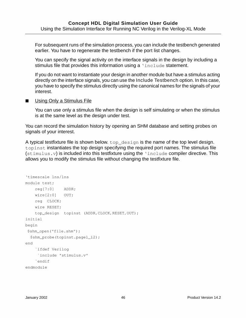
Concept HDL Digital Simulation User GuideUsing the Simulation Interface for Running NC Verilog in the Verilog-XL Mode
For subsequent runs of the simulation process, you can include the testbench generatedearlier. You have to regenerate the testbench if the port list changes.
You can specify the signal activity on the interface signals in the design by including astimulus file that provides this information using a ‘include statement.
If you do not want to instantiate your design in another module but have a stimulus actingdirectly on the interface signals, you can use the Include Testbench option. In this case,you have to specify the stimulus directly using the canonical names for the signals of yourinterest.
■ Using Only a Stimulus File
You can use only a stimulus file when the design is self simulating or when the stimulusis at the same level as the design under test.
You can record the simulation history by opening an SHM database and setting probes onsignals of your interest.
A typical testfixture file is shown below. top_design is the name of the top level design.topinst instantiates the top design specifying the required port names. The stimulus file(stimulus.v) is included into this testfixture using the ‘include compiler directive. Thisallows you to modify the stimulus file without changing the testfixture file.
‘timescale 1ns/1ns
module test;
reg[7:0] ADDR;
wire[2:0] OUT;
reg CLOCK;
wire RESET;
top_design topinst (ADDR,CLOCK,RESET,OUT);
initial
begin
$shm_open("file.shm");
$shm_probe(topinst.page1_i2);
end
`ifdef Verilog
`include "stimulus.v"
`endif
endmodule
January 2002 46 Product Version 14.2

Concept HDL Digital Simulation User GuideUsing the Simulation Interface for Running NC Verilog in the Verilog-XL Mode
You can specify your stimulus in terms of always and initial blocks in Verilog. You canuse Verilog canonical names to specify the signals. A sample Verilog stimulus file is givenbelow:
always
#150 CLOCK = ~CLOCK;
initial
begin
CLOCK = 1;
$deposit(RESET , 1'b0);
# 100;
$deposit(RESET, 1);
# 20000;
$finish;
end
Generating a Testbench
To generate a testbench, it is necessary that the simulation netlist for the design, /sim_sch_1/verilog.v, is already created. This netlist is required for generating thetestbench.
After the netlist is generated, you can generate the testbench. To generate the testbench,complete the following steps:
1. Select the Stimulus tab in the NC (VXL mode) setup dialog box.
2. Select the Generate Testbench option.
3. Specify the path to the stimulus file (which specifies the signal activity on the interfacesignals) in the Stimulus File field, or click Browse to select the stimulus file.
The specified stimulus file will be included through the ‘include directive in thetestfixture module.
4. Specify the name of the design instance in the Design Instance field. The default valueis top.
5. Enter the time scale directive for the testbench module in the Time Scale field.
6. Click Generate to generate the testbench module. Click Edit to edit the testbenchmodule.
The testbench file verilog.v is created in the following directory:
<project_directory>/worklib/testfixture/<design_name>_sim_sch_1
January 2002 47 Product Version 14.2
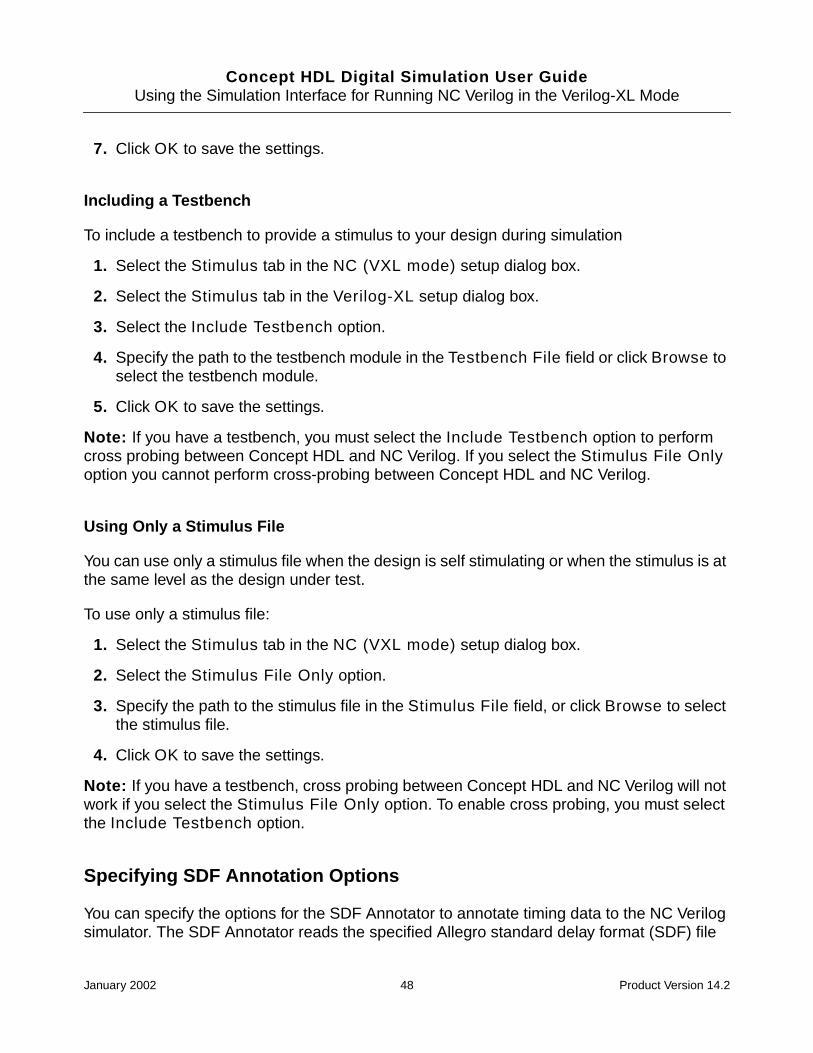
Concept HDL Digital Simulation User GuideUsing the Simulation Interface for Running NC Verilog in the Verilog-XL Mode
7. Click OK to save the settings.
Including a Testbench
To include a testbench to provide a stimulus to your design during simulation
1. Select the Stimulus tab in the NC (VXL mode) setup dialog box.
2. Select the Stimulus tab in the Verilog-XL setup dialog box.
3. Select the Include Testbench option.
4. Specify the path to the testbench module in the Testbench File field or click Browse toselect the testbench module.
5. Click OK to save the settings.
Note: If you have a testbench, you must select the Include Testbench option to performcross probing between Concept HDL and NC Verilog. If you select the Stimulus File Onlyoption you cannot perform cross-probing between Concept HDL and NC Verilog.
Using Only a Stimulus File
You can use only a stimulus file when the design is self stimulating or when the stimulus is atthe same level as the design under test.
To use only a stimulus file:
1. Select the Stimulus tab in the NC (VXL mode) setup dialog box.
2. Select the Stimulus File Only option.
3. Specify the path to the stimulus file in the Stimulus File field, or click Browse to selectthe stimulus file.
4. Click OK to save the settings.
Note: If you have a testbench, cross probing between Concept HDL and NC Verilog will notwork if you select the Stimulus File Only option. To enable cross probing, you must selectthe Include Testbench option.
Specifying SDF Annotation Options
You can specify the options for the SDF Annotator to annotate timing data to the NC Verilogsimulator. The SDF Annotator reads the specified Allegro standard delay format (SDF) file
January 2002 48 Product Version 14.2

Concept HDL Digital Simulation User GuideUsing the Simulation Interface for Running NC Verilog in the Verilog-XL Mode
and annotates the timing data to the simulator. The Allegro SDF file is generated using theAllegro a2sdf wire delay extract utility. This file contains compensated switch and settledelays and rise and fall propagation delays. For more information on the SDF Annotator andSDF files, see the SDF Annotator Guide.
1. Select the Allegro SDF tab in the NC (VXL mode) setup dialog box.
2. Select the Perform SDF Annotation check box if you want to perform SDF annotation.
3. Specify the path to the Allegro SDF file or click Browse to select the SDF file.
The SDF Annotator reads this SDF file. This file does not appear on the Verilogcommand line.
Note: You should not specify FPGA/CPLD SDF files in this field.
4. Define the Scope by specifying the name of the module instance.
The SDF Annotator uses the hierarchy level of this instance for running the annotation.
5. Select the appropriate delay type to indicate how the SDF Annotator should annotatedelay values to the NC Verilog simulator.
6. Select the appropriate scale type to indicate how the SDF Annotator should scale thetiming data from the SDF file before it is annotated to the NC Verilog simulator.
7. Enter the scale factor.
The scale factor is a set of three real number multipliers in the form ofmin_mult:typ_mult:max_mult that the SDF Annotator uses to scale the minimum, typical,and maximum timing data from the SDF file before it is annotated to the NC Verilogsimulator.
8. Select the Generate SDF Back Annotation Log check box to generate the log fileduring annotation. The log file is generated in the run directory.
The SDF Annotator writes status information, warnings, and error messages to the logfile during the annotation process. These messages also include the configuration of theannotator, assumptions made during annotation, and warnings or errors due to
Select To
Minimum Annotate the minimum delay value.
Typical Annotate the typical delay value.
Maximum Annotate the maximum delay value.
Tool Control Annotate with the delay type selected in the Simulation tab.
January 2002 49 Product Version 14.2
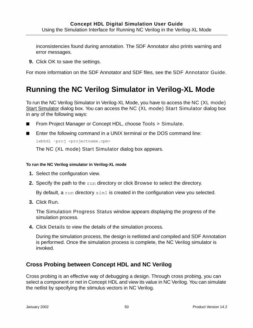
Concept HDL Digital Simulation User GuideUsing the Simulation Interface for Running NC Verilog in the Verilog-XL Mode
inconsistencies found during annotation. The SDF Annotator also prints warning anderror messages.
9. Click OK to save the settings.
For more information on the SDF Annotator and SDF files, see the SDF Annotator Guide.
Running the NC Verilog Simulator in Verilog-XL Mode
To run the NC Verilog Simulator in Verilog-XL Mode, you have to access the NC (XL mode)Start Simulator dialog box. You can access the NC (XL mode) Start Simulator dialog boxin any of the following ways:
■ From Project Manager or Concept HDL, choose Tools > Simulate.
■ Enter the following command in a UNIX terminal or the DOS command line:
lwbhdl -proj <projectname.cpm>
The NC (XL mode) Start Simulator dialog box appears.
To run the NC Verilog simulator in Verilog-XL mode
1. Select the configuration view.
2. Specify the path to the run directory or click Browse to select the directory.
By default, a run directory sim1 is created in the configuration view you selected.
3. Click Run.
The Simulation Progress Status window appears displaying the progress of thesimulation process.
4. Click Details to view the details of the simulation process.
During the simulation process, the design is netlisted and compiled and SDF Annotationis performed. Once the simulation process is complete, the NC Verilog simulator isinvoked.
Cross Probing between Concept HDL and NC Verilog
Cross probing is an effective way of debugging a design. Through cross probing, you canselect a component or net in Concept HDL and view its value in NC Verilog. You can simulatethe netlist by specifying the stimulus vectors in NC Verilog.
January 2002 50 Product Version 14.2

Concept HDL Digital Simulation User GuideUsing the Simulation Interface for Running NC Verilog in the Verilog-XL Mode
To select components or nets in Concept HDL and view their value in NC Verilog,
1. In Concept HDL, click the component instance or the signal.
The component or the signal gets selected.
2. In NC Verilog, do one of the following:
❑ Click Show Value.
NC Verilog displays the value of the selected cell or net.
❑ Click Wave Trace.
Signalscan Waves displays the selected cell or net value in a wave form.
You can select multiple objects in Concept HDL and highlight all of them together in NCVerilog by creating a group in Concept HDL. This feature is useful when you want to displaya number of signals in Signalscan Waves by selecting the signals from Concept HDL.
To cross probe multiple objects,
1. In Concept HDL, create a group by choosing Group > Create > By Rectangle.
For more information, see Working with Groups in the Concept HDL User Guide.
2. Select the objects you want to cross probe.
3. Press Esc, or type ; in the Concept HDL console to complete the formation of the group.
4. With the cursor on the Concept HDL window:
❑ In UNIX, click the middle mouse button.
❑ In Windows NT, press Ctrl and click the left mouse button.
5. Switch to NC Verilog to look at the highlighted objects. If you are in a different scope thanwhat Concept HDL is in, you may not see the objects highlighted. You can set the scopeappropriately to see the objects highlighted. However, it is not necessary for you tochange to the right scope to perform any of the display or debug operations.
6. Click the SimWave button to bring up Signalscan Waves with the selected signals.
Note: Cross-probing will not work if you have a testbench and you select the Stimulus FileOnly option in the Stimulus (Verilog) tab of the NC (VXL Mode) setup dialog box. If you havea testbench, select the Include Testbench option in the Stimulus (Verilog) tab of the NC(VXL Mode) setup dialog box. The Stimulus File Only option should be selected only whenthe design is self-stimulating or when the stimulus is at the same level as the design undertest. For more information, see Providing a Testfixture for Verilog Simulation on page 45.
January 2002 51 Product Version 14.2

Concept HDL Digital Simulation User GuideUsing the Simulation Interface for Running NC Verilog in the Verilog-XL Mode
In Verilog, you can have multiple highest level modules. You can have the design under testas one top level module and the stimulus as the other top level module. This allows you tospecify the stimulus directly accessing the nets and ports in the design using Verilogcanonical paths. In this case, the cross-probing utility translates the Concept HDL names ofthe selected objects to their respective Verilog canonical names.
January 2002 52 Product Version 14.2

Concept HDL Digital Simulation User Guide
5Using the Leapfrog Simulation Interface
You can simulate your VHDL designs from Concept HDL using the Leapfrog simulator. Digitalsimulation using the Leapfrog simulator involves the following tasks:
1. Selecting the Leapfrog Simulator
2. Setting Up the Leapfrog Simulation Interface
3. Creating a new design configuration or modifying an existing design configuration usingthe Hierarchy Editor tool. For more information, see Appendix C, “SimulationConfigurations.”
4. Running simulation on your design using the specified design configuration. The designis netlisted and compiled, and the Leapfrog simulator is invoked. For more information,see Running the Leapfrog Simulator.
5. Simulating your design using the simulator.
6. Browsing waveforms and debugging your design. You can cross probe betweenConcept HDL and Leapfrog to quickly debug your design.
Selecting the Leapfrog Simulator
To use the Leapfrog simulator for simulating a design, you have to select the Leapfrogsimulator. To do this
1. Start Project Manager.
2. Open the project.
3. Choose Tools > Setup.
The Project Setup window appears.
4. Select the Tools tab.
5. Click Simulation Setup.
January 2002 53 Product Version 14.2

Concept HDL Digital Simulation User GuideUsing the Leapfrog Simulation Interface
The Choose Simulator dialog box appears.
6. Select the Leapfrog option and click OK.
Setting Up the Leapfrog Simulation Interface
You can set up the following to run the Leapfrog simulator:
■ Specify netlisting options.
For more information, see Specifying Leapfrog Netlisting Options on page 54.
■ Specify simulation options.
For more information, see Specifying Leapfrog Simulation Options on page 57.
■ Specify Leapfrog compiler options.
For more information, see Specifying Leapfrog Compiler (cv) Options on page 58.
■ Specify Leapfrog elaborator options.
For more information, see Specifying Leapfrog Elaborator (ev) Options on page 59.
■ Specify Leapfrog simulator options. For more information, see Specifying LeapfrogSimulator (sv) Options on page 61.
■ Provide a testfixture for VHDL simulation. For more information, see Providing aTestfixture for VHDL Simulation on page 62.
■ Specify options for performing SDF annotation. For more information, see SpecifyingAllegro SDF Annotation Options on page 63.
To specify Leapfrog options you need to open the Leapfrog setup dialog box. To do this:
1. In Concept HDL, choose Tools > Simulate.
The Leapfrog Start Simulator dialog box appears.
2. Click Setup.
The Leapfrog setup dialog box appears.
Specifying Leapfrog Netlisting Options
1. Select the Netlist tab in the Leapfrog setup dialog box.
January 2002 54 Product Version 14.2
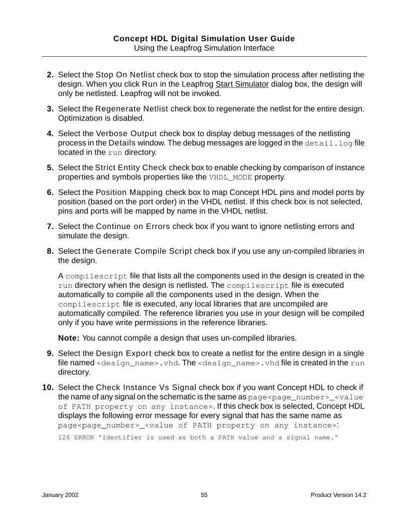
Concept HDL Digital Simulation User GuideUsing the Leapfrog Simulation Interface
2. Select the Stop On Netlist check box to stop the simulation process after netlisting thedesign. When you click Run in the Leapfrog Start Simulator dialog box, the design willonly be netlisted. Leapfrog will not be invoked.
3. Select the Regenerate Netlist check box to regenerate the netlist for the entire design.Optimization is disabled.
4. Select the Verbose Output check box to display debug messages of the netlistingprocess in the Details window. The debug messages are logged in the detail.log filelocated in the run directory.
5. Select the Strict Entity Check check box to enable checking by comparison of instanceproperties and symbols properties like the VHDL_MODE property.
6. Select the Position Mapping check box to map Concept HDL pins and model ports byposition (based on the port order) in the VHDL netlist. If this check box is not selected,pins and ports will be mapped by name in the VHDL netlist.
7. Select the Continue on Errors check box if you want to ignore netlisting errors andsimulate the design.
8. Select the Generate Compile Script check box if you use any un-compiled libraries inthe design.
A compilescript file that lists all the components used in the design is created in therun directory when the design is netlisted. The compilescript file is executedautomatically to compile all the components used in the design. When thecompilescript file is executed, any local libraries that are uncompiled areautomatically compiled. The reference libraries you use in your design will be compiledonly if you have write permissions in the reference libraries.
Note: You cannot compile a design that uses un-compiled libraries.
9. Select the Design Export check box to create a netlist for the entire design in a singlefile named <design_name>.vhd. The <design_name>.vhd file is created in the rundirectory.
10. Select the Check Instance Vs Signal check box if you want Concept HDL to check ifthe name of any signal on the schematic is the same as page<page_number>_<valueof PATH property on any instance>. If this check box is selected, Concept HDLdisplays the following error message for every signal that has the same name aspage<page_number>_<value of PATH property on any instance>:
126 ERROR "Identifier is used as both a PATH value and a signal name."
January 2002 55 Product Version 14.2
Concept HDL Digital Simulation User GuideUsing the Leapfrog Simulation Interface
11. Select the Optimize Unnamed Nets check box when you want that the simulationnetlist should have minimum number of alias statements and no unnamed signaldeclarations.
Although, selecting the Optimize Unnamed Nets check box removes repeated andunwanted alias statements from the netlist, occurrences of unnamed statements are notremoved from the netlist indiscriminately. There are situations where in the unnamedstatement are required in the netlist. For example, aliasing is not done in cases whereREMOVE= EXCLUDE is attached to a design component. In such cases, only wiredeclarations of the unnamed statement is removed from the netlist.
12. If you do not want components in some libraries to be netlisted, specify the list of suchlibraries in the Exclude libraries field.
Specify a library and press Enter to specify each additional library.
This option is provided to prevent Concept HDL from netlisting components of libraries:
❑ to which you do not have write permissions.
❑ to which you have write permissions, but do not want the components in suchlibraries to be netlisted.
13. Specify the maximum number of netlisting errors that you want to allow in the design. Thedefault number is 50.
If the number of netlisting errors in the design exceed the number specified here,Concept HDL will not generate the netlist.
14. Specify the VHDL logic type for all the vectored ports and signals in the design. You canspecify any legal VHDL vector type, such as STD_LOGIC_VECTOR and BIT_VECTOR.The default value is STD_LOGIC_VECTOR.
Note: The specified vector type applies to all drawings in the design. You can overridethe vector type for individual drawings by using the VHDL_VECTOR_TYPE property on aVHDL_DECS symbol. For more information on the VHDL_VECTOR_TYPE property and theVHDL_DECS symbol, see the Concept HDL User Guide.
15. Specify the VHDL logic type for all scalar ports and signals in the design. You can specifyany legal VHDL scalar type, such as STD_LOGIC and BIT. The default value isSTD_LOGIC.
Note: The specified scalar type applies to all drawings in the design. You can overridethe scalar type for individual drawings by using the VHDL_SCALAR_TYPE property on aVHDL_DECS symbol. For more information on the VHDL_SCALAR_TYPE property and theVHDL_DECS symbol, see the Concept HDL User Guide.
January 2002 56 Product Version 14.2

Concept HDL Digital Simulation User GuideUsing the Leapfrog Simulation Interface
16. Specify the names of the libraries that are to be used in VHDL library clauses in theVHDL entity and architecture text generated from the schematic. If you do not specify alibrary, IEEE will be used as the default library.
You can also add libraries for a drawing by using the LIBRARY property on a VHDL_DECSsymbol. In the VHDL entity and architecture text generated from the schematic, thelibraries on the symbol will be appended to the list of libraries you specify here.
17. Specify the names that are to be used in VHDL use clauses in the VHDL entity andarchitecture text generated from the schematic. Use the following syntax for adding useclauses. There is no limit on the number of use clauses you can add. If you do not specifyany use clauses, IEEE.STD_LOGIC_1164.ALL will be used as the default.
You can also add use clauses for a drawing by using the USE property on a VHDL_DECSsymbol. In the VHDL entity and architecture text generated from the schematic, the useclauses on the symbol will be appended to the list of use clauses you specify here.
18. Click OK to save the settings.
Specifying Leapfrog Simulation Options
1. Select the Simulation tab in the Leapfrog setup dialog box.
2. Select the Invoke Leapfrog Notebook check box if you want to start the LeapfrogNotebook when you run the simulation.
3. Specify the command-line options to run the Leapfrog Notebook. For more information,see the Leapfrog Notebook User Guide.
4. Select the Compile Design check box if you want to compile your design using theLeapfrog compiler (cv) every time you run the simulation.
5. Select the Elaborate Design check box if you want to elaborate your design using theLeapfrog elaborator (ev) every time you run the simulation.
6. Select the Simulate check box if you want to simulate your design using the Leapfrogsimulator (sv) every time you run the simulation. The simulator will not be invoked if thischeck box is not selected.
7. Select the Generate Configuration option to run the Hierarchy Editor and generate theconfiguration cfg_vhdl.
a. Specify the name of the configuration library.
b. Specify the name of the configuration cell.
January 2002 57 Product Version 14.2

Concept HDL Digital Simulation User GuideUsing the Leapfrog Simulation Interface
8. Select the Include Configuration option to include the configuration in the compilescript.
a. Specify the name of the configuration library.
b. Specify the name of the configuration cell.
9. Click OK to save the settings.
Specifying Leapfrog Compiler (cv) Options
1. Select the Compile tab in the Leapfrog setup dialog box.
2. Select the Produce Source Listing check box to generate a VHDL source listing withstandard error messages inserted at the point of the error. This listing file has theextension .lst. If the input is from the standard input, the file is named as stdin.lst.
3. Select the Produce Extended Listing check box to generate a VHDL source listing withextended error messages inserted at the point of the error. This listing file has theextension .lst. If the input is from the standard input, the file is named as stdin.lst.
If the Produce Source Listing check box is also selected, the compiler includesextended error messages, as well as the standard error messages.
4. Select the Display Messages check box to display informative messages duringcompilation. The messages summarize errors and warnings accumulated during theanalysis of each VHDL source file.
5. Select the Exclude Debug Information check box to disable bounds checks andunderflow or overflow checks during compilation.
❑ Select the Disable Bounds Checks check box to disable bounds checks duringcompilation.
❑ Select the Disable Under/Over Check check box to disable underflow or overflowchecks during compilation.
6. Specify any other legal Leapfrog compiler (cv) options in the Other Options field.
For a list of cv options, see the “cv Command –Line Format” section in Chapter 3,“Compilation and the cv Command” of the Leapfrog VHDL Simulator Reference.
7. Select the Disable RTL Acceleration check box to disable optimization of IEEE 1164data types and functions.
8. Select the Disable Vital Acceleration check box to suppress acceleration and VITALlevel-1 compliance checks. Use this option if you require the regular Leapfrog debugcapability for a VITAL model.
January 2002 58 Product Version 14.2

Concept HDL Digital Simulation User GuideUsing the Leapfrog Simulation Interface
Note: If you select this check box, the Disable Timing Checks, Enable NameChecks, Disable Messages, and Disable X Generation options have no effect.
9. Select the Disable Timing Checks check box to suppress all timing checks, periodchecks, and recovery removal checks in level-1 compliant architectures duringcompilation.
If the Disable Vital Acceleration check box is selected, this option has no effect.
10. Select the Disable Messages check box to suppress message generation from timingchecks and path delays during VITAL acceleration.
If the Disable Vital Acceleration check box is selected, this option has no effect.
11. Select the Enable Name Checks check box to perform name checks for the use ofgenerics and signals inside a VITAL model. These checks are not required by VITAL butare recommended. By default, name checks are disabled.
If the Disable Vital Acceleration check box is selected, this option has no effect.
12. Select the Disable X Generation check box to suppress message generation fromtiming checks and path delays during VITAL acceleration.
If the Disable Vital Acceleration check box is selected, this option has no effect.
13. Click OK to save the settings.
Specifying Leapfrog Elaborator (ev) Options
1. Select the Elaborate tab in the Leapfrog setup dialog box.
2. Select the Display Messages check box to display messages about the elaborationprocess as it occurs. The messages include summaries of the processes and signals inthe simulation, as well as the name of the simulation data file. This information isdesirable when ev computes the default simulation name.
3. Select the Preserve Resolution check box to generate reflexive signal calls to theresolution function.
Note: Selecting this option reduces simulation performance.
For information on reflexive signals see the “The Reflexive Property of ResolvedSignals” section in Chapter 4, “Elaboration and the ev Command” of the LeapfrogVHDL Simulator Reference.
4. Select the Compatible Mode check box to specify the vendor compatibility mode, inwhich the elaborator accepts several common variations in VHDL constructs.
January 2002 59 Product Version 14.2

Concept HDL Digital Simulation User GuideUsing the Leapfrog Simulation Interface
For more information, see “The -compatibility Option” section in Appendix A,“Leapfrog Simulator and LRM Compliance” of the Leapfrog VHDL SimulatorReference.
5. Select the Exclude Debug Information check box to reduce the simulation snapshotsize by omitting debug information.
6. Select the Update out-of-date Designs check box to update the simulation snapshotby recompiling design units whose time stamp is more recent than the simulationsnapshot.
Select the Check for out-of-date Sources check box to check the source filesassociated with the design unit being elaborated during the update process. If a sourcefile exists that is more recent than the compiled design unit, the elaborator compiles thesource file and includes its design unit in the snapshot.
The Check for out-of-date Sources option is enabled only if the Update out-of-dateDesigns check box is selected.
7. Specify any other legal Leapfrog elaborator (ev) option in the Other Options field.
For a list of ev options, see the “ev Command –Line Format” section in Chapter 4,“Elaboration and the ev Command” of the Leapfrog VHDL Simulator Reference.
8. Select the Disable Input Port Delays check box to make the elaborator ignore thelumped interconnect delays specified on input ports in the WIREDDELAY block. Use thisoption to speed up simulation of circuits when the input port delays should be ignored.
By default, this option causes the delayed signal to be collapsed to the port unless youspecify the -nocollapse option.
9. Select the Unit Delay Gates check box to convert the delays on all primitive instancesto the minimum unit of time used in the model.
10. Select the Simulation Units check box to elaborate the design using a unit of time youspecify.
a. Enter a time value in the first field.
b. Click on the drop-down in the second field to select the time unit type (us, ns, ps,or fs).
11. Click on the Simple Delay Gates drop-down to specify the delay value.
Select To
default Specify that the default delay value is the average of alldelays.
January 2002 60 Product Version 14.2

Concept HDL Digital Simulation User GuideUsing the Leapfrog Simulation Interface
12. Click OK to save the settings.
Specifying Leapfrog Simulator (sv) Options
1. Select the Simulate tab in the Leapfrog setup dialog box.
2. Select the Display Messages check box to display messages about the simulationprocess as it occurs.
3. Select the Compatible Mode check box to enable the vendor compatibility mode, whichallows the simulator to accept several common variations in VHDL constructs.
For more information, see “The -compatibility Option” section in Appendix A,“Leapfrog Simulator and LRM Compliance” of the Leapfrog VHDL SimulatorReference.
4. Select the Update Out-of-date Designs check box to update all design units justbefore simulation is invoked so that design units are up to date with the snapshot.
Select the Check for out-of-date Sources check box to check the source filesassociated with the design unit being simulated. If a source file exists that is more recentthan the compiled design unit, the simulator compiles and elaborates the source file intothe snapshot.
The Check for out-of-date Sources option is enabled only if the Update out-of-dateDesigns check box is selected.
5. Specify any other legal Leapfrog compiler (sv) option in the Other Options field.
For a list sv options, see the “sv Invocation Options” section in Chapter 5, “TheLeapfrog VHDL Simulator and the sv Command” of the Leapfrog VHDL SimulatorReference.
6. Click OK to save the settings.
max Specify that all delays are the value of the maximum delay.
min Specify that all delays are the value of the minimum delay
average Specify that all delays are the average value of all theindividual input-output delays for that primitive instance
Select To
January 2002 61 Product Version 14.2

Concept HDL Digital Simulation User GuideUsing the Leapfrog Simulation Interface
Providing a Testfixture for VHDL Simulation
You can simulate your design either by instantiating the top level design in a testfixturemodule, or by including a test vector generator in the schematic. You can provide thetestfixture by using any of the following methods:
■ Generating a Testbench
You can generate a testbench that instantiates the top level module with a port list. Allthe interface signals in your design are listed in the port list of the generated testbench.You have to regenerate the testbench if the port list changes.
■ Including a Testbench
For subsequent runs of the simulation process, you can include the testbench generatedearlier. You have to regenerate the testbench if the port list changes.
Generating a Testbench
Before you start generating the testbench, ensure that the simulation netlist is present in thesim_sch_1 view. To generate a testbench:
1. Select the Stimulus tab in the Leapfrog setup dialog box.
2. Select the Generate Testbench option.
3. Specify the VHDL entity architecture for which you want to generate the testbench file inthe format lib.cell:view or lib.cell, in the Input Design field.
4. Select the Overwrite check box if you want to overwrite any existing testbench file withthe same path name as the one generated by you.
5. Specify the name of the testbench file in the format lib.cell:view in the Design Unitfield.
6. Click Generate to generate the testbench module. Click Edit to edit the testbenchmodule.
7. Click OK to save the settings.
Including a Testbench
To include a testbench to provide a stimulus to your design during simulation
1. Select the Stimulus tab in the Leapfrog setup dialog box.
2. Select the Include Testbench option.
January 2002 62 Product Version 14.2

Concept HDL Digital Simulation User GuideUsing the Leapfrog Simulation Interface
3. Specify the path to the testbench module in the Design Unit field in the formatlib.cell:view.
4. Click Edit if you want to edit the testbench module.
5. Click OK to save the settings.
Specifying Allegro SDF Annotation Options
You can specify the options for the SDF Annotator to annotate timing data to the Leapfrogsimulator. The SDF Annotator reads the specified Allegro standard delay format (SDF) fileand annotates the timing data to the simulator. The Allegro SDF file is generated using theAllegro a2sdf wire delay extract utility. This file contains compensated switch and settledelays and rise and fall propagation delays. For more information on the SDF Annotator andSDF files, see the SDF Annotator Guide.
1. Select the Allegro SDF tab in the Leapfrog setup dialog box.
2. Select the Perform SDF Annotation check box if you want to perform SDF annotation.
3. Specify the name of the Allegro SDF file or click Browse to select the SDF file. This fileis processed and converted to a format that is used by Leapfrog to perform SDF backannotation.
4. Specify the directory where the processed SDF file will be stored. The processed SDFfile is used by Leapfrog to perform SDF annotation.
5. Define the Scope by specifying the name of the module instance. Specify the top levelmodule to which this delay applies. For example, if the testfixture module is calledtestbench and the instance name of the Concept HDL design is top, you need to entertestbench.top in this field.
The SDF Annotator uses the hierarchy level of this instance for running the annotation.
6. Select the appropriate delay type to indicate how the SDF Annotator should annotatedelay values to the Leapfrog simulator.
Select To
Minimum Annotate the minimum delay value.
Typical Annotate the typical delay value.
Maximum Annotate the maximum delay value.
Tool Control Annotate with the delay type selected in the Leapfrog:Simulation tab.
January 2002 63 Product Version 14.2

Concept HDL Digital Simulation User GuideUsing the Leapfrog Simulation Interface
7. Select the Generate SDF Back Annotation Log check box to generate the log fileduring annotation. The log file is generated in the run directory.
The SDF Annotator writes status information, warnings, and error messages to the logfile during the annotation process. These messages also include the configuration of theannotator, assumptions made during annotation, and warnings or errors due toinconsistencies found during annotation. The SDF Annotator also prints warning anderror messages.
8. Click OK to save the settings.
For more information on the SDF Annotator and SDF files, see the SDF Annotator Guide.
Importing Verilog Models into the Leapfrog VHDLSimulator
You can import the Verilog models of your design units into the Leapfrog VHDL simulator. Formore information, see Appendix B, “Importing Verilog-XL Models into Leapfrog,” in theLeapfrog VHDL Simulator User Guide.
Verilog Cosimulation
The simulation of a Verilog model in a VHDL environment is done by Verilog cosimulation.Leapfrog invokes Verilog-XL in slave mode when it encounters a VHDL wrapper for a Verilogmodel. For more information, see the Leapfrog VHDL Simulator User Guide.
Running the Leapfrog Simulator
To run the Leapfrog simulator, you have to access the Leapfrog Start Simulator dialog box.You can access the Leapfrog Start Simulator dialog box in any of the following ways:
■ From Project Manager or Concept HDL, choose Tools > Simulate.
■ Enter the following command in a UNIX terminal or the DOS command line:
lwbhdl -proj <projectname.cpm>
The Leapfrog Start Simulator dialog box appears.
To run the Leapfrog simulator
1. Select the configuration view.
January 2002 64 Product Version 14.2

Concept HDL Digital Simulation User GuideUsing the Leapfrog Simulation Interface
2. Specify the path to the run directory or click Browse to select the directory.
3. Click Run.
The Simulation Progress Status window appears displaying the progress of thesimulation process.
4. Click Details to view the details of the simulation process.
Cross Probing between Concept HDL and Leapfrog
Cross probing is an effective way of debugging a design. Through cross probing, you canselect a component or net in Concept HDL and view its value in Leapfrog. You can simulatethe netlist by specifying the stimulus vectors in Leapfrog.
To select components or nets in Concept HDL and view their value in Leapfrog,
1. In Concept HDL, click the component instance or the signal.
The component or the signal gets selected.
2. In Leapfrog, do one of the following:
❑ Click Show Value.
Leapfrog displays the value of the selected cell or net.
❑ Click Wave Trace.
Signalscan Waves displays the selected cell or net value in a wave form.
You can select multiple objects in Concept HDL and highlight all of them together in Leapfrogby creating a group in Concept HDL. This feature is useful when you want to display anumber of signals in Signalscan Waves by selecting the signals from Concept HDL.
To cross probe multiple objects,
1. In Concept HDL, create a group by choosing Group > Create > By Rectangle.
For more information, see Working with Groups in the Concept HDL User Guide.
2. Select the objects you want to cross probe.
3. Press Esc, or type ; in the Concept HDL console to complete the formation of the group.
4. With the mouse focused on the Concept HDL window, click the middle mouse button.
5. Switch to Leapfrog to look at the highlighted objects. If you are in a different scope thanwhat Concept HDL is in, you may not see the objects highlighted. You can set the scope
January 2002 65 Product Version 14.2

Concept HDL Digital Simulation User GuideUsing the Leapfrog Simulation Interface
appropriately to see the objects highlighted. However, it is not necessary for you tochange to the right scope to perform any of the display or debug operations.
6. Click the SimWave button to bring up Signalscan Waves with the selected signals.
January 2002 66 Product Version 14.2
Concept HDL Digital Simulation User Guide
6Using the NC VHDL Simulation Interface
You can simulate your VHDL designs from Concept HDL using the NC VHDL simulator.Digital simulation using the NC VHDL simulator involves the following tasks:
1. Selecting the NC VHDL Simulator
2. Setting Up the NC VHDL Simulation Interface
3. Creating a new design configuration or modifying an existing design configuration usingthe Hierarchy Editor tool. For more information, see Appendix C, “SimulationConfigurations.”
4. Running a simulation on your design using the specified design configuration. Thedesign is netlisted and compiled, and the NC VHDL simulator is invoked. For moreinformation, see Running the NC VHDL Simulator.
5. Simulating your design using the simulator.
6. Browsing waveforms and debugging your design. You can cross probe betweenConcept HDL and NC VHDL to quickly debug your design.
Selecting the NC VHDL Simulator
To use the NC VHDL simulator for simulating a design, you have to select the NC VHDLsimulator. To do this
1. Start Project Manager.
2. Open the project.
3. Select Tools > Setup.
The Project Setup window appears.
4. Select the Tools tab.
5. Click Simulation Setup.
January 2002 67 Product Version 14.2
Concept HDL Digital Simulation User GuideUsing the NC VHDL Simulation Interface
The Choose Simulator dialog box appears.
6. Select the NC VHDL option and click OK.
Setting Up the NC VHDL Simulation Interface
You can set up the following to run the NC VHDL simulator:
■ Specify netlisting options.
For more information, see Specifying NC VHDL Netlisting Options on page 69.
■ Specify simulation options.
For more information, see Specifying NC VHDL Simulation Options on page 71.
■ Provide testfixture for VHDL simulation.
For more information, see Providing a Testfixture for VHDL Simulation on page 72.
■ Specify options for performing SDF annotation.
For more information, see Specifying Allegro SDF Annotation Options on page 73.
To specify the NC VHDL options, you must access the NC VHDL setup dialog box. You canaccess the NC VHDL setup dialog box in the following ways:
■ From the Project Setup window
a. In Project Manager, choose Tools > Setup.
The Project Setup window appears.
b. Select the Tools tab.
c. Click Simulation Setup.
The Choose Simulator dialog box appears.
d. Select the NC VHDL option and click Setup.
The NC VHDL setup dialog box appears.
■ From Project Manager or Concept HDL
a. Choose Tools > Simulate.
The NC VHDL Start Simulator dialog box appears.
January 2002 68 Product Version 14.2
Concept HDL Digital Simulation User GuideUsing the NC VHDL Simulation Interface
b. Click Setup.
The NC VHDL setup dialog box appears.
Specifying NC VHDL Netlisting Options
1. Select the Netlist tab in the NC VHDL setup dialog box.
2. Select the Stop On Netlist check box to stop the simulation process after netlisting thedesign. When you click Run in the NC VHDL Start Simulator dialog box, the design willonly be netlisted. NC VHDL will not be invoked.
3. Select the Regenerate Netlist check box to regenerate the netlist for the entire design.Optimization is disabled.
4. Select the Verbose Output check box to display debug messages of the netlistingprocess in the Details window. The debug messages are logged in the detail.log filelocated in the run directory.
5. Select the Strict Entity Check check box to enable checking by comparison of instanceproperties and symbols properties like the VHDL_MODE property.
6. Select the Position Mapping check box to map Concept HDL pins and model ports byposition (based on the port order) in the VHDL netlist. If this check box is not selected,pins and ports will be mapped by name in the VHDL netlist.
7. Select the Continue on Errors check box if you want to ignore netlisting errors andsimulate the design.
8. Select the Generate Compile Script check box if you use any un-compiled libraries inthe design.
A compilescript file that lists all the components used in the design is created in therun directory when the design is netlisted. The compilescript file is executedautomatically to compile all the components used in the design. When thecompilescript file is executed, any local libraries that are uncompiled areautomatically compiled. The reference libraries you use in your design will be compiledonly if you have write permissions in the reference libraries.
Note: You cannot compile a design that uses un-compiled libraries.
9. Select the Design Export check box to create a netlist for the entire design in a singlefile named <design_name>.vhd. The <design_name>.vhd file is created in the rundirectory.
10. Select the Check Instance Vs Signal check box if you want Concept HDL to check ifthe name of any signal on the schematic is the same as page<page_number>_<value
January 2002 69 Product Version 14.2

Concept HDL Digital Simulation User GuideUsing the NC VHDL Simulation Interface
of PATH property on any instance>. If this check box is selected, Concept HDLdisplays the following error message for every signal that has the same name aspage<page_number>_<value of PATH property on any instance>:
126 ERROR "Identifier is used as both a PATH value and a signal name."
11. Select the Optimize Unnamed Nets check box when you want that the simulationnetlist should have minimum number of alias statements and no unnamed signaldeclarations.
Although, selecting the Optimize Unnamed Nets check box removes repeated andunwanted alias statements from the netlist, occurrences of unnamed statements are notremoved from the netlist indiscriminately. There are situations where in the unnamedstatement are required in the netlist. For example, aliasing is not done in cases whereREMOVE= EXCLUDE is attached to a design component. In such cases, only wiredeclarations of the unnamed statement is removed from the netlist.
12. If you do not want components in some libraries to be netlisted, specify the list of suchlibraries in the Exclude libraries field.
Specify a library and press Enter to specify each additional library.
This option is provided to prevent Concept HDL from netlisting components of libraries
❑ to which you do not have write permissions, and
❑ to which you have write permissions, but do not want the components to benetlisted.
13. Specify the maximum number of netlisting errors that you want to allow in the design. Thedefault number is 50.
If the number of netlisting errors in the design exceeds the number specified here,Concept HDL will not generate the netlist.
14. Specify the VHDL logic type for all the vectored ports and signals in the design. You canspecify any legal VHDL vector type, such as STD_LOGIC_VECTOR and BIT__VECTOR.The default value is STD_LOGIC_VECTOR.
Note: The specified vector type applies to all drawings in the design. You can overridethe vector type for individual drawings by using the VHDL_VECTOR_TYPE property on aVHDL_DECS symbol. For more information on the VHDL_VECTOR_TYPE property and theVHDL_DECS symbol, see the Concept HDL User Guide.
15. Specify the VHDL logic type for all scalar ports and signals in the design. You can specifyany legal VHDL scalar type, such as STD_LOGIC and BIT. The default value isSTD_LOGIC.
Note: The specified scalar type applies to all drawings in the design. You can override
January 2002 70 Product Version 14.2

Concept HDL Digital Simulation User GuideUsing the NC VHDL Simulation Interface
the scalar type for individual drawings by using the VHDL_SCALAR_TYPE property on aVHDL_DECS symbol. For more information on the VHDL_SCALAR_TYPE property and theVHDL_DECS symbol, see the Concept HDL User Guide.
16. Specify the names of the libraries that are to be used in VHDL library clauses in theVHDL entity and architecture text generated from the schematic. If you do not specify alibrary, IEEE will be used as the default library.
You can also add libraries for a drawing by using the LIBRARY property on a VHDL_DECSsymbol. In the VHDL entity and architecture text generated from the schematic, thelibraries on the symbol will be appended to the list of libraries you specify here.
17. Specify the names that are to be used in VHDL use clauses in the VHDL entity andarchitecture text generated from the schematic. Use the following syntax for adding useclauses. There is no limit on the number of use clauses you can add. If you do not specifyany use clauses, IEEE.STD_LOGIC_1164.ALL will be used as the default.
You can also add use clauses for a drawing by using the USE property on a VHDL_DECSsymbol. In the VHDL entity and architecture text generated from the schematic, the useclauses on the symbol will be appended to the list of use clauses you specify here.
18. Click OK to save the settings.
Specifying NC VHDL Simulation Options
1. Select the Simulation tab in the NC VHDL setup dialog box.
2. Specify the path to the hdl.var file or click Browse to select the file.
3. Enter the path to the directory where you want the following log files to be created:
❑ ncvhdl.log, which contains the messages logged when the design is compiled.
❑ ncelab.log, which contains the messages logged when the design is elaborated.
❑ ncsim.log, which contains the messages logged when the design is simulated.
By default the log files are created in the run directory.
4. Select the Compile check box if you want to compile the design every time you run thesimulation.
Enter additional command-line options for ncvhdl in the Cmd Options field.
5. Select the Elaborate check box if you want to elaborate the design every time you runthe simulation.
Enter additional command-line options for ncelab in the Cmd Options field.
January 2002 71 Product Version 14.2

Concept HDL Digital Simulation User GuideUsing the NC VHDL Simulation Interface
6. Select the Simulate check box if you want to simulate the design in the NC VHDLsimulator every time you run the simulation. The simulator will not be invoked if this checkbox is not selected.
Enter additional command-line options for ncsim in the Cmd Options field.
7. Select
❑ the Generate Configuration option to run the Hierarchy Editor and generate theconfiguration cfg_vhdl.
❑ the Include Configuration option to include the configuration in the compile script.
8. Specify the name of the configuration library in the Library Name field.
9. Specify the name of the configuration cell in the Cell Name field.
10. Click OK to save the settings.
Providing a Testfixture for VHDL Simulation
You can simulate your design either by instantiating the top level design in a testfixturemodule or by including a test vector generator in the schematic. You can provide thetestfixture by one of the following methods:
■ Generating a Testbench
You can generate a testbench that instantiates the top level module with a port list. Allthe interface signals in your design are listed in the port list of the generated testbench.You have to regenerate the testbench if the port list changes.
■ Including a Testbench
For subsequent runs of the simulation process, you can include the testbench generatedearlier. You have to regenerate the testbench if the port list changes.
Generating a Testbench
Generating a testbench for the simulations is a two step process. The first step is to generatethe simulation netlist and then, the second step is to generate the testbench.
To generate the simulation netlist, select the Stop On Netlist check box on the Netlist taband then run the simulator. To know more about netlisting options, see Specifying NC VHDLNetlisting Options.
January 2002 72 Product Version 14.2

Concept HDL Digital Simulation User GuideUsing the NC VHDL Simulation Interface
After the simulation netlist is generated, you can generate the testbench for the design. Togenerate a testbench, complete the following steps:
1. Select the Stimulus tab in the NC VHDL setup dialog box.
2. Select the Generate Testbench option.
3. Specify the VHDL entity architecture for which you want to generate the testbench file inthe format lib.cell:view or lib.cell in the Input Design field.
4. Select the Overwrite check box if you want to overwrite any existing testbench file withthe same path as the one generated by you.
5. Specify the name of the testbench file in the format lib.cell:view in the Design Unitfield.
6. Click Generate to generate the testbench module. Click Edit to edit the testbenchmodule.
The testbench file vhdl.vhd is created in the following directory:
<project_directory>/worklib/testfixture/vhl_rtl/
7. Click OK to save the settings.
Including a Testbench
To include a testbench to provide a stimulus to your design during simulation,
1. Select the Stimulus tab in the NC VHDL setup dialog box.
2. Select the Include Testbench option.
3. Specify the path to the testbench module in the Design Unit field in the formatlib.cell:view.
4. Click Edit if you want to edit the testbench module.
5. Click OK to save the settings.
Specifying Allegro SDF Annotation Options
You can specify the options for the SDF Annotator to annotate timing data to the NC VHDLsimulator. The SDF Annotator reads the specified Allegro standard delay format (SDF) fileand annotates the timing data to the simulator. The Allegro SDF file is generated using theAllegro a2sdf wire delay extract utility. This file contains compensated switch and settle
January 2002 73 Product Version 14.2

Concept HDL Digital Simulation User GuideUsing the NC VHDL Simulation Interface
delays and rise and fall propagation delays. For more information on the SDF Annotator andSDF files, see the SDF Annotator Guide.
1. Select the Allegro SDF tab in the NC VHDL setup dialog box.
2. Select the Perform SDF Annotation check box if you want to perform SDF annotation.
3. Specify the Allegro SDF file or click Browse to select the SDF file. This file is processedand converted to a format that is used by NC VHDL to perform SDF back annotation.
4. Specify the directory where the processed SDF file will be stored. The processed SDFfile is used by NC VHDL to perform SDF annotation.
5. Define the Scope by specifying the name of the module instance. Specify the top levelmodule to which this delay applies. For example, if the testfixture module is calledtestbench and the instance name of the Concept HDL design is top, you need to entertestbench.top in this field.
The SDF Annotator uses the hierarchy level of this instance for running the annotation.
6. Select the appropriate delay type to indicate how the SDF Annotator should annotatedelay values to the NC VHDL simulator.
7. Select the Generate SDF Back Annotation Log check box to generate the log fileduring annotation. The log file is generated in the run directory.
The SDF Annotator writes status information, warnings, and error messages to the logfile during the annotation process. These messages also include the configuration of theannotator, assumptions made during annotation, and warnings or errors due toinconsistencies found during annotation. The SDF Annotator also prints warning anderror messages.
8. Click OK to save the settings.
For more information on the SDF Annotator and SDF files, see the SDF Annotator Guide.
Select To
Minimum Annotate the minimum delay value.
Typical Annotate the typical delay value.
Maximum Annotate the maximum delay value.
Tool Control Annotate with the delay type selected in the NC VHDL:Simulation tab.
January 2002 74 Product Version 14.2

Concept HDL Digital Simulation User GuideUsing the NC VHDL Simulation Interface
Importing Verilog Models into the NC VHDL Simulator
You can import the Verilog models of your design units into the NC VHDL simulator using thencshell utility. For more information, see Chapter 12, “Utilities,” in the Affirma NC VHDLSimulator Help.
Simulating Designs with SWIFT and Hardware Models
The NC VHDL simulator supports three modeling interfaces that let you integrate hardwaremodels into your simulation: the SmartModel SWIFT Interface, the LMSI Hardware ModelingInterface, and the OMI interface. For more information, see Chapter 16, “Using LMCSmartModels and Hardware Models,” in the Affirma NC VHDL Simulator Help.
Running the NC VHDL Simulator
To run the NC VHDL simulator, you have to access the NC VHDL Start Simulator dialog box.You can access the NC VHDL Start Simulator dialog box in any of the following ways:
■ From Project Manager or Concept HDL, choose Tools > Simulate.
■ Enter the following command in a UNIX terminal or at the DOS command prompt:
lwbhdl -proj <projectname.cpm>
The NC VHDL Start Simulator dialog box appears.
To run the NC VHDL simulator
1. Select the configuration view.
2. Specify the path to the run directory or click Browse to select the directory.
By default, a run directory, sim1 is created in the configuration view you selected. Oneof the files in run directory is design.f. This file contains a list of all the VHDL filesrequired to simulate your design.
3. Click Run.
The Simulation Progress Status window appears displaying the progress of thesimulation process.
4. Click Details to view the details of the simulation process.
January 2002 75 Product Version 14.2
Concept HDL Digital Simulation User GuideUsing the NC VHDL Simulation Interface
During the simulation process, the design is netlisted, elaborated and compiled and SDFannotation is performed. Once the simulation process is complete, the NC VHDLsimulator is invoked.
Cross Probing between Concept HDL and NC VHDL
Cross probing is an effective way of debugging a design. Through cross probing, you canselect a component or net in Concept HDL and view its value in NC VHDL. You can simulatethe netlist by specifying the stimulus vectors in NC VHDL.
To select components or nets in Concept HDL and view their value in NC VHDL,
1. In Concept HDL, click the component instance or the signal.
The component or the signal gets selected.
2. In NC VHDL, do one of the following:
❑ Click Show Value.
NC VHDL displays the value of the selected cell or net.
❑ Click Wave Trace.
Signalscan Waves displays the selected cell or net value in a wave form.
You can select multiple objects in Concept HDL and highlight all of them together in NC VHDLby creating a group in Concept HDL. This feature is useful when you want to display anumber of signals in Signalscan Waves by selecting the signals from Concept HDL.
To cross probe multiple objects,
1. In Concept HDL, create a group by choosing Group > Create > By Rectangle.
For more information, see Working with Groups in the Concept HDL User Guide.
2. Select the objects you want to cross probe.
3. Press Esc, or type ; in the Concept HDL console to complete the formation of the group.
4. With the cursor in the Concept HDL window:
❑ In UNIX, click the middle mouse button.
❑ In Windows NT, press Control and click the left mouse button.
5. Switch to NC VHDL to look at the highlighted objects. If you are in a different scope thanwhat Concept HDL is in, you may not see the objects highlighted. You can set the scope
January 2002 76 Product Version 14.2

Concept HDL Digital Simulation User GuideUsing the NC VHDL Simulation Interface
appropriately to see the objects highlighted. However, it is not necessary for you tochange to the right scope to perform any of the display or debug operations.
6. Click the SimWave button to bring up Signalscan Waves with the selected signals.
January 2002 77 Product Version 14.2

Concept HDL Digital Simulation User Guide
7Supporting Third-Party Verilog and VHDLSimulators
Concept HDL supports third-party Verilog and VHDL simulators by allowing you to generatethe netlist that you can use with third-party simulators.
For more information, see:
■ Supporting Third-Party Verilog Simulators on page 78
■ Supporting Third-Party VHDL Simulators on page 82
Supporting Third-Party Verilog Simulators
You can choose to netlist your design using Concept HDL and simulate the design using third-party Verilog simulators.
Generating the netlist for use with third-party Verilog simulators involves the following:
■ Selecting the Third-Party Verilog Simulator Option on page 78
■ Specifying Netlisting Options for Third-Party Verilog Simulators on page 79
■ Generating the Netlist for Third-Party Verilog Simulators on page 81
■ Files Required by Third-Party Verilog Simulators on page 82
Selecting the Third-Party Verilog Simulator Option
To select the third-party Verilog simulator option,
1. Start Project Manager.
2. Open the project.
3. Choose Tools > Setup.
January 2002 78 Product Version 14.2

Concept HDL Digital Simulation User GuideSupporting Third-Party Verilog and VHDL Simulators
The Project Setup window appears.
4. Select the Tools tab.
5. Click Simulation Setup.
The Choose Simulator dialog box appears.
6. Select the Third Party Verilog option and click OK.
Specifying Netlisting Options for Third-Party Verilog Simulators
To specify the netlisting options you must access the Third Party Verilog setup dialog box.You can access the Third Party Verilog setup dialog box in the following ways:
■ From the Project Setup window
a. In Project Manager, choose Tools > Setup.
The Project Setup window appears.
b. Select the Tools tab.
c. Click Simulation Setup.
The Choose Simulator dialog box appears.
d. Select the Third Party Verilog option, and click Setup.
The Third Party Verilog setup dialog box appears.
■ From Project Manager or Concept HDL
a. Choose Tools > Simulate.
The Third Party Verilog Start Simulator dialog box appears.
b. Click Setup.
The Third Party Verilog setup dialog box appears.
To specify the netlisting options
1. Select the Regenerate Netlist check box to regenerate the netlist for the entire design.Optimization is disabled.
January 2002 79 Product Version 14.2
Concept HDL Digital Simulation User GuideSupporting Third-Party Verilog and VHDL Simulators
2. Select the Verbose Output check box to display debug messages of the netlistingprocess in the Details window. The debug messages are logged in the detail.log filelocated in the run directory.
3. Select the Uppercase Identifiers check box to write all lowercase identifiers such asmodule names, signal names and instance names in uppercase in the netlist.
4. Select the Position Mapping check box to map Concept HDL pins and model ports byposition (based on the port order) in the Verilog netlist. If this check box is not selected,pins and ports will be mapped by name in the Verilog netlist.
5. Select the Design Export check box to create a netlist for the entire design in a singlefile named <design_name>.v. The <design_name>.v file is created in the rundirectory.
6. Select the Check Instance Vs Signal check box if you want Concept HDL to check ifthe name of any signal on the schematic is the same as page<page_number>_<valueof PATH property on any instance>. If this check box is selected, Concept HDLdisplays the following error message for every signal that has the same name aspage<page_number>_<value of PATH property on any instance>:
126 ERROR "Identifier is used as both a PATH value and a signal name."
7. Select the Optimize Unnamed Nets check box when you want that the simulationnetlist should have minimum number of alias statements and no unnamed signaldeclarations.
Although, selecting the Optimize Unnamed Nets check box removes repeated andunwanted alias statements from the netlist, occurrences of unnamed statements are notremoved from the netlist indiscriminately. There are situations where in the unnamedstatement are required in the netlist. For example, aliasing is not done in cases whereREMOVE= EXCLUDE is attached to a design component. In such cases, only wiredeclarations of the unnamed statement is removed from the netlist.
8. If you do not want components in some libraries to be netlisted, specify the list of suchlibraries in the Exclude libraries field.
Specify a library and press Enter to specify each additional library.
This option is provided to prevent Concept HDL from netlisting components of libraries
❑ to which you do not have write permissions, and
❑ to which you have write permissions, but do not want the components to benetlisted.
9. Specify the maximum number of netlisting errors that you want to allow in the design. Thedefault number is 50.
January 2002 80 Product Version 14.2

Concept HDL Digital Simulation User GuideSupporting Third-Party Verilog and VHDL Simulators
If the number of netlisting errors in the design exceed the number specified here,Concept HDL will not generate the netlist.
10. Specify the timescale directive for the Verilog module of the schematic. The default valueis 1ns/1ps.
11. Specify the logic type for all nets in the design. You can use any legal Verilog net type,such as WIRE, WAND, and WOR. The default value is WIRE. For more information onVerilog logic types for nets, see the Concept HDL User Guide.
Note: The specified net type applies to all drawings in the design. You can override thenet type for individual drawings by using the VLOG_NET_TYPE property on aVERILOG_DECS symbol.
12. Specify the signal names for the Verilog net type Supply 0.
13. Specify the signal names for the Verilog net type Supply 1.
14. Click OK to save the settings.
Generating the Netlist for Third-Party Verilog Simulators
To generate the netlist for third-party Verilog simulators, you have to access the Third PartyVerilog Start Simulator dialog box. You can access the Third Party Verilog Start Simulatordialog box in any of the following ways:
■ From Project Manager or Concept HDL, choose Tools > Simulate.
■ Enter the following command in a UNIX terminal or at the DOS command prompt:
lwbhdl -proj <projectname.cpm>
The Third Party Verilog Start Simulator dialog box appears.
To generate the netlist for third-party Verilog simulators
1. Select the configuration view.
2. Specify the path to the run directory or click Browse to select the directory.
By default, a run directory, sim1 is created in the configuration view you selected.
3. Click Run.
The Simulation Progress Status window appears displaying the progress of thenetlisting process.
4. Click Details to view the details of the netlisting process.
January 2002 81 Product Version 14.2

Concept HDL Digital Simulation User GuideSupporting Third-Party Verilog and VHDL Simulators
The Verilog netlist is generated. The global signals module for the design is alsogenerated.
Once the netlisting process is complete, the simulation interface displays the list of files youneed to use for simulating your design. For more information, see Files Required by Third-Party Verilog Simulators on page 82.
Files Required by Third-Party Verilog Simulators
The following files are required for simulating your design using third-party Verilog simulators.
■ The <project_directory>/glbl/<design_name>_cfg_verilog/verilog.vfile that contains the Verilog module global signals used in your design.
■ The <design_name>.f file that contains paths to Verilog modules for all instances inyour design. You need to create the <design_name>.f file.
■ An allegro.sdf file that contains the $sdf_annotate task for annotation of wiredelays. The allegro.sdf file is generated by Allegro.
Supporting Third-Party VHDL Simulators
You can choose to netlist your design using Concept HDL and simulate the design using third-party VHDL simulators.
Generating the netlist for use with third-party VHDL simulators involves the following:
■ Selecting the Third-Party VHDL Simulator Option on page 82
■ Specifying Netlisting Options for Third-Party VHDL Simulators on page 83
■ Generating the Netlist for Third-Party VHDL Simulators on page 85
■ Files Required by Third-Party VHDL Simulators on page 86
Selecting the Third-Party VHDL Simulator Option
To select the third-party VHDL simulator option:
1. Start Project Manager.
2. Open the project.
3. Select Tools > Setup.
January 2002 82 Product Version 14.2

Concept HDL Digital Simulation User GuideSupporting Third-Party Verilog and VHDL Simulators
The Project Setup window appears.
4. Select the Tools tab.
5. Click Simulation Setup.
The Choose Simulator dialog box appears.
6. Select the Third Party VHDL option and click OK.
Specifying Netlisting Options for Third-Party VHDL Simulators
To specify the netlisting options you must access the Third Party VHDL setup dialog box.You can access the Third Party VHDL setup dialog box in the following ways:
■ From the Project Setup window
a. In Project Manager, choose Tools > Setup.
The Project Setup window appears.
b. Select the Tools tab.
c. Click Simulation Setup.
The Choose Simulator dialog box appears.
d. Select the Third Party VHDL option, and click Setup.
The Third Party VHDL setup dialog box appears.
■ From Project Manager or Concept HDL
a. In Concept HDL, choose Tools > Simulate.
The Third Party VHDL Start Simulator dialog box appears.
b. Click Setup.
The Third Party VHDL setup dialog box appears.
To specify the netlisting options
1. Select the Regenerate Netlist check box to regenerate the netlist for the entire design.Optimization is disabled.
January 2002 83 Product Version 14.2

Concept HDL Digital Simulation User GuideSupporting Third-Party Verilog and VHDL Simulators
2. Select the Verbose Output check box to display debug messages of the netlistingprocess in the Details window. The debug messages are logged in the detail.log filelocated in the run directory.
3. Select the Strict Entity Check check box to enable checking by comparison of instanceproperties and symbols properties like the VHDL_MODE property.
4. Select the Position Mapping check box to map Concept HDL pins and model ports byposition (based on the port order) in the VHDL netlist. If this check box is not selected,pins and ports will be mapped by name in the VHDL netlist.
5. Select the Design Export check box to create a netlist for the entire design in a singlefile named analyst.v. The analyst.v file is created in the run directory.
6. Select the Check Instance Vs Signal check box if you want Concept HDL to check ifthe name of any signal on the schematic is the same as page<page_number>_<valueof PATH property on any instance>. If this check box is selected, Concept HDLdisplays the following error message for every signal that has the same name aspage<page_number>_<value of PATH property on any instance>:
126 ERROR "Identifier is used as both a PATH value and a signal name."
7. Select the Optimize Unnamed Nets check box when you want that the simulationnetlist should have minimum number of alias statements and no unnamed signaldeclarations.
Although, selecting the Optimize Unnamed Nets check box removes repeated andunwanted alias statements from the netlist, occurrences of unnamed statements are notremoved from the netlist indiscriminately. There are situations where in the unnamedstatement are required in the netlist. For example, aliasing is not done in cases whereREMOVE= EXCLUDE is attached to a design component. In such cases, only wiredeclarations of the unnamed statement is removed from the netlist.
8. If you do not want components in some libraries to be netlisted, specify the list of suchlibraries in the Exclude libraries field.
Specify a library and press Enter to specify each additional library.
This option is provided to prevent Concept HDL from netlisting components of libraries
❑ to which you do not have write permissions, and
❑ to which you have write permissions, but do not want the components to benetlisted.
9. Specify the maximum number of netlisting errors that you want to allow in the design. Thedefault number is 50.
January 2002 84 Product Version 14.2
Concept HDL Digital Simulation User GuideSupporting Third-Party Verilog and VHDL Simulators
If the number of netlisting errors in the design exceeds the number specified here,Concept HDL will not generate the netlist.
10. Specify the VHDL logic type for all the vectored ports and signals in the design. You canspecify any legal VHDL vector type, such as STD_LOGIC_VECTOR and BIT_VECTOR.The default value is STD_LOGIC_VECTOR.
Note: The specified vector type applies to all drawings in the design. You can overridethe vector type for individual drawings by using the VHDL_VECTOR_TYPE property on aVHDL_DECS symbol. For more information on the VHDL_VECTOR_TYPE property and theVHDL_DECS symbol, see the Concept HDL User Guide.
11. Specify the VHDL logic type for all scalar ports and signals in the design. You can specifyany legal VHDL scalar type, such as STD_LOGIC and BIT. The default value isSTD_LOGIC.
Note: The specified scalar type applies to all drawings in the design. You can overridethe scalar type for individual drawings by using the VHDL_SCALAR_TYPE property on aVHDL_DECS symbol. For more information on the VHDL_SCALAR_TYPE property and theVHDL_DECS symbol, see the Concept HDL User Guide.
12. Specify the names of the libraries that are to be used in VHDL library clauses in theVHDL entity and architecture text generated from the schematic. If you do not specify alibrary, IEEE will be used as the default library.
You can also add libraries for a drawing by using the LIBRARY property on a VHDL_DECSsymbol. In the VHDL entity and architecture text generated from the schematic, thelibraries on the symbol will be appended to the list of libraries you specify here.
13. Specify the names that are to be used in VHDL use clauses in the VHDL entity andarchitecture text generated from the schematic. Use the following syntax for adding useclauses. There is no limit on the number of use clauses you can add. If you do not specifyany use clauses, IEEE.STD_LOGIC_1164.ALL will be used as the default.
You can also add use clauses for a drawing by using the USE property on a VHDL_DECSsymbol. In the VHDL entity and architecture text generated from the schematic, the useclauses on the symbol will be appended to the list of use clauses you specify here.
14. Click OK to save the settings.
Generating the Netlist for Third-Party VHDL Simulators
To generate the netlist for third-party VHDL simulators, you have to access the Third PartyVHDL Start Simulator dialog box. You can access the Third Party VHDL Start Simulatordialog box in any of the following ways:
January 2002 85 Product Version 14.2

Concept HDL Digital Simulation User GuideSupporting Third-Party Verilog and VHDL Simulators
■ From Project Manager or Concept HDL, choose Tools > Simulate.
■ Enter the following command in a UNIX terminal or at the DOS command prompt:
lwbhdl -proj <projectname.cpm>
The Third Party VHDL Start Simulator dialog box appears.
To generate the netlist for third-party VHDL simulators
1. Select the configuration view.
2. Specify the path to the run directory or click Browse to select the directory.
By default, a run directory, sim1 is created in the configuration view you selected.
3. Click Run.
The Simulation Progress Status window appears displaying the progress of thenetlisting process.
4. Click Details to view the details of the netlisting process.
The VHDL netlist is generated. The global signals package for the design is alsogenerated.
Once the netlisting process is complete, the simulation interface displays the list of files youneed to use for simulating your design. For more information, see Files Required by Third-Party VHDL Simulators on page 86.
Files Required by Third-Party VHDL Simulators
The following files are required for simulating your design using third-party VHDL simulators.
■ The <project_directory>/glbl/<design_name>_cfg_vhdl/vhdl.vhd filethat contains the VHDL module for global signals used in your design.
■ The <design_name>.f file that contains paths to VHDL modules for all instances inyour design. You need to create the <design_name>.f file.
■ An allegro.sdf file that contains the $sdf_annotate task for annotation of wiredelays. The allegro.sdf file is generated by Allegro.
January 2002 86 Product Version 14.2

Concept HDL Digital Simulation User Guide
8Asymmetrical Parts
This chapter introduces you to asymmetrical parts and split parts. Because of technologicaladvances, it is now possible to have parts that have different logic for different sections. Suchparts are called asymmetrical parts. Some parts also have the pincount going up to a fewthousands of pins. Such parts are called large pin count devices. In this chapter, we will seehow these parts are simulated in Concept HDL.
The types of parts covered in this chapter are:
■ Split parts
■ Asymmetrical parts
■ MultiSection parts (with common pins within a section)
Split Part
Whenever a device has large pincount, it becomes impossible to instantiate the complete partas a single symbol in a schematic. Therefore, these parts are usually broken or split intomultiple body drawings. Parts that can split into multiple symbols are called split parts. Whenyou split a part into multiple symbols, you can handle them easily in the design. Although theuse of split parts makes it easy for designers to handle large pin count devices, these partscannot be simulated individually. All symbols have to be combined together and simulated asa single device.
January 2002 87 Product Version 14.2

Concept HDL Digital Simulation User GuideAsymmetrical Parts
Figure 8-1 Block Diagram Representing Split Parts
Asymmetrical Part
Parts that have different logic within a single package, such as an IC, are called asymmetricalparts. These parts are represented using multiple symbols where each symbol representsone logical function. You can simulate each section of an asymmetrical part individually.
January 2002 88 Product Version 14.2

Concept HDL Digital Simulation User GuideAsymmetrical Parts
Figure 8-2 Asymmetrical Parts with Common Pins
Figure 8-3 Asymmetrical Parts with Different Assertions
January 2002 89 Product Version 14.2

Concept HDL Digital Simulation User GuideAsymmetrical Parts
Note: Split parts are used to represent different logic of an asymmetrical part. Therefore, anasymmetrical part can be a split part but all split parts are not asymmetrical.
MultiSection Parts with Common Pins
These are parts with multiple bodies having a common pin. These parts can be simulatedseparately.
Note: Multi section parts with common pins have the same assertion for the common pins.This is unlike asymmetrical parts that have different assertions for common pins.
Simulation Properties for the Split Parts
While simulating a schematic design, you need to consider the simulation model thatrepresents a design component. You can have simulation models both for a split part and thecomplete part.
In such situations, you need to attach special simulation properties on the split part to indicatewhether it should be simulated individually or grouped with other split parts to be simulatedas a single part. To simulate multiple split parts as a single part, all instances of split partshave to be merged to generate a simulation netlist.
Concept HDL supports two special properties for split parts, SPLIT_INST andSPLIT_INST_NAME. You need to add either the SPLIT_INST property or theSPLIT_INST_NAME property on all instances or bodies representing one physical model.
Using the SPLIT_INST Property
One of the ways in which split parts can be used in a schematic is be using the SPLIT_INSTproperty. Each split part of a device must have a SPLIT_INST property set to TRUE attachedto the symbol (by the librarian developing the split parts). If this property is not attached to thesymbols, then the property must be attached to the split parts when used in a Concept HDLschematic.
Along with the SPLIT_INST property it is recommended that the LOCATION property shouldalso be used. All the parts with the SPLIT_INST property set to TRUE and having the samevalue for the $LOCATION property form a split instance group. A split instance group is agroup of split parts of the same device.
In case the LOCATION property is not specified, Concept HDL netlister merges all theinstances of a part with the SPLIT_INST property set to TRUE into a single instance in the
January 2002 90 Product Version 14.2

Concept HDL Digital Simulation User GuideAsymmetrical Parts
simulation netlist using some internal logic. In the simulation netlist generated, the instancename is <part_name>_split_1 by default.
For example, consider a large pin count device, ASYM_PART, represented using twosymbols. Each symbol is called a split part of the device. Both the symbols have theSPLIT_INST property set to TRUE, and are instantiated in a schematic design. In thesimulation netlist generated by Concept HDL netlister, both the symbols will be merged intoa single instance, with instance name as ASYM_PART_split_1.
If a design has more than one instance of the same symbol with the SPLIT_INST propertyset to TRUE, Concept HDL netlister will generate a warning and group the components usingsome internal logic. To remove this warning, you must add the LOCATION property on all thesplit parts that are to be grouped together.
For example, consider a schematic that has two instances of ASYM_PART, which is a splitpart represented by two symbols sym_1 and sym_2. Let’s say, I1 and I2 represent sym_1,and I3 and I4 represent sym_2. If you want I1 and I3 to be merged together, and I2 andI4 to be merged together, you must specify the LOCATION property for at least one splitgroup, I1 and I3 or I2 and I4.
In the simulation netlist, all parts having the same value for the LOCATION property aremerged into a single instance and the value of the LOCATION property becomes the instancename.
Using the SPLIT_INST_NAME Property
The SPLIT_INST_NAME property is attached on all split parts that have to be merged into asingle instance in the netlist. Using the SPLIT_INST_NAME property is same as using theSPLIT_INST property.
Therefore, statement:
SPLIT_INST_NAME=ic1
is equivalent to the following two statements put together:
SPLIT_INST = TRUE
LOCATION= ic1
Concept HDL netlister merges the instances with the same SPLIT_INST_NAME propertyvalue to a single instance. The value assigned to the SPLIT_INST_NAME property becomesthe default instance name and should be same for all the split parts of a device.
The value assigned to the SPLIT_INST_NAME property, is case insensitive. Therefore, if onesplit part has SPLIT_INST_NAME = IC1 attached to it and the other has
January 2002 91 Product Version 14.2

Concept HDL Digital Simulation User GuideAsymmetrical Parts
SPLIT_INST_NAME = ic1 attached to it, both the parts will be merged into a singleinstance in the netlist.
Example:
Suppose there is a large pin count device ASYM_PART that is divided into four split parts,each of which is represented by a different symbol. To merge all these symbols into a singleinstance after netlisting, attach the SPLIT_INST_NAME property with the same value, saySPLIT_INST_NAME = ic1, to all four split parts. As a result, in the netlist all these fourparts form the same split instance group.
Split parts that are generated using Part Developer have either the SPLIT_INST property setto TRUE and $LOCATION = ? property or the $SPLIT_INST_NAME property attached tothem. For such split parts, you may or may not assign a value to the $LOCATION property orthe $SPLIT_INST_NAME property depending on whether one or multiple instances of thesplit part are used in a schematic.
If there is only one instance of the split part in the schematic, the correct simulation netlist isgenerated even if the value of $LOCATION (or $SPLIT_INST_NAME) is not specified. In casethere are multiple instances of the split part, it is recommended that you provide values foreither the $LOCATION property or the $SPLIT_INST_NAME property, as the case may be.
Working with the SPLIT_INST_NAME and the SPLIT_INST Properties
There are a few points that you must remember while working with the SPLIT_INST andSPLIT_INST_NAME properties.
■ A combination of SPLIT_INST_NAME and SPLIT_INST attached to the same instanceis not supported. If a component has both these properties attached to it, Concept HDLnetlister reads the SPLIT_INST_NAME property and ignores the SPLIT_INST property.
However, if you have one part with SPLIT_INST_NAME = ABC and other part withSPLIT_INST = TRUE and LOCATION = ABC, both the parts will be merged into thesame split inst group in the netlist by Concept HDL netlister.
■ SPLIT_INST_NAME and SPLIT_INST = TRUE property names and values are treatedas case insensitive. Therefore, split_inst_name and SPLIT_INST_NAME are bothsupported. Parts having SPLIT_INST_NAME=ic1 and split_inst_name=IC1 aretreated in the same split instance group.
■ Concept HDL handles SPLIT_INST_NAME and SPLIT_INST properties across thepages.
January 2002 92 Product Version 14.2

Concept HDL Digital Simulation User GuideAsymmetrical Parts
■ The SIM_MAP_VIEW and the SIM_BIND_VIEW property names and values are treatedas case insensitive on Windows NT platform. On UNIX-based platforms, the valuesassigned to these properties are case sensitive.
Note: The SIM_BIND_VIEW property is also used to bind specify the wrapper view forthe component to which it is attached. To know more about SIM_BIND_VIEW, seeCadence document PCB Systems Properties Reference. To know about bindingasymmetrical parts to wrappers, see Working with Wrappers.
If you need to specify the SIM_BIND_VIEW/SIM_MAP_VIEW property for a split group,you need to add the property with the same property value on all the split parts in thegroup.
Example:
Consider that a split group has three split parts; A, B, and C. By default, all three will bebound to the view that has the highest precedence in the expand.cfg file. By default,it is the vlog_map view. In case you want to bind the split parts to some other view, youneed to attach either the SIM_BIND_VIEW or SIM_MAP_VIEW property on all in threeparts. If the SIM_BIND_VIEW (or SIM_MAP_VIEW) property is not attached to all parts,you can have following possibilities:
Part A Part B Part C Result
Case I
None None SIM_BIND_VIEW= swift_model
No error, but a wrongnetlist is generated. In thenetlist pins correspondingto part A and B are readfrom vlog_map, whereas pins corresponding topart C will be read fromthe swift_model.Therefore, half the netlistwill have port informationand half the netlist willhave the pin information.
January 2002 93 Product Version 14.2
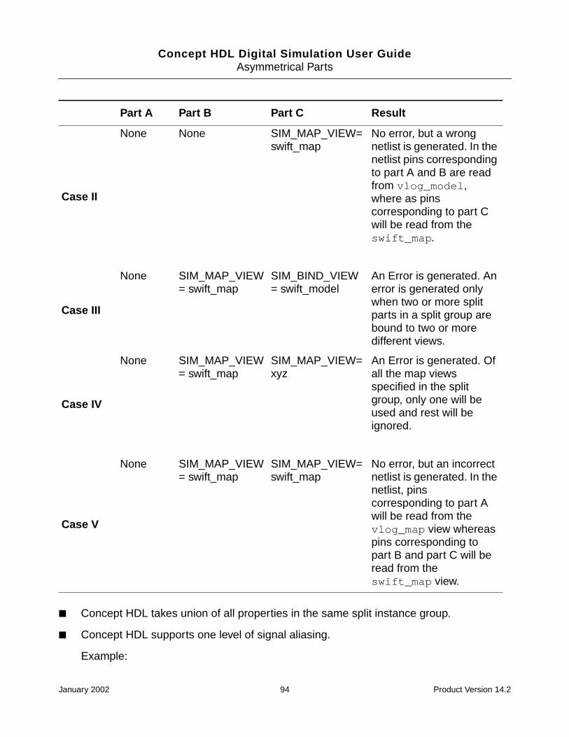
Concept HDL Digital Simulation User GuideAsymmetrical Parts
■ Concept HDL takes union of all properties in the same split instance group.
■ Concept HDL supports one level of signal aliasing.
Example:
Case II
None None SIM_MAP_VIEW=swift_map
No error, but a wrongnetlist is generated. In thenetlist pins correspondingto part A and B are readfrom vlog_model,where as pinscorresponding to part Cwill be read from theswift_map.
Case III
None SIM_MAP_VIEW= swift_map
SIM_BIND_VIEW= swift_model
An Error is generated. Anerror is generated onlywhen two or more splitparts in a split group arebound to two or moredifferent views.
Case IV
None SIM_MAP_VIEW= swift_map
SIM_MAP_VIEW=xyz
An Error is generated. Ofall the map viewsspecified in the splitgroup, only one will beused and rest will beignored.
Case V
None SIM_MAP_VIEW= swift_map
SIM_MAP_VIEW=swift_map
No error, but an incorrectnetlist is generated. In thenetlist, pinscorresponding to part Awill be read from thevlog_map view whereaspins corresponding topart B and part C will beread from theswift_map view.
Part A Part B Part C Result
January 2002 94 Product Version 14.2
Concept HDL Digital Simulation User GuideAsymmetrical Parts
Suppose signal A1 is connected to a common pin OE on one part and signal A2 isconnected to pin OE on some other parts in same split instance group and if A1 and A2are aliased, Concept HDL uses the signal on the instance with lower path value.
Concept HDL does not support multiple signal aliasing. For example, a situation wheresignal A1 is aliased to A3 and A3 is aliased to A2, is not supported. In other words,Concept HDL does not support the syntax, .
■ Use split parts of a large pin count device only at the same level of the drawing. Thismeans, you cannot use split parts of the same split instance group at different levels ofthe hierarchy.
■ You cannot use split parts in the Re-use blocks.
■ Error message is highlighted only on one part of the split instance group. It is not alwaysnecessary that the marker will highlight the property/pin name error correctly on thecorrect instance of same split instance group.
Example:
Suppose there is a pin name Q<5> that appears on instance I2 of the split instancegroup. This pin may not exist on some other instances (I1) of the same split instancegroup. In this situation, Concept HDL might propagate some error related to pin Q<5> oninstance I1.
■ There is no support for Text Macros by the SPLIT_INST_NAME property value.
Example:
If SPLIT_INST_NAME=%SNAME is used on an instance inside a block and SNAME isdefined as SNAME=INST1\PARAMETER on one of the blocks andSNAME=INST2\PARAMETER on the same reused block, Concept HDL will not substitutevalue of SNAME in SPLIT_INST_NAME property value. Concept HDL treats %SNAME asa property value.
Examples
Example of Split Parts
When you use split parts to represent a part in the schematic, you must add either theSPILT_INST_NAME property or the SPLIT_INST property on all the split parts.
Depending on the selection made by the user, split parts that are developed using PartDeveloper have either the $SPLIT_INST_NAME property or the $LOCATION and theSPLIT_INST property set to TRUE attached to them.
A1 A2 A3≡ ≡
January 2002 95 Product Version 14.2

Concept HDL Digital Simulation User GuideAsymmetrical Parts
An example of a split part developed using Part Developer is shown below. Both the partshave the SPLIT_INST = TRUE and $LOCATION properties attached to them. No value hasbeen assigned to the $LOCATION property.
The simulation netlist for the above schematic is listed below:
‘timescale 1ns/1ns
module top (val, clk );
// generated by HDL Direct 14.2-a021 Oct 22, 2001 11:03:00 IST
// on Mon Oct 29 15:57:36 2001
// from split_test_lib/TOP/sch_1
January 2002 96 Product Version 14.2

Concept HDL Digital Simulation User GuideAsymmetrical Parts
output [3:0] val;
input clk;
wire fif;
wire fif_n;
// begin instances
M16 COUNTER16_SPLIT_1 (.altFifteen(fif_n),
.clock(clk),
.fifteen(fif),
.value({val[3], val[2], val[1], val[0]}));
endmodule // top(sch_1)
In the netlist, both the instances have been merged to a single netlist. In the above example,the physical design will have only one counter16 on the PCB.
A part of the schematic with two instances of counter16 is shown below. Notice thatinstances I5 and I6 have the LOCATION property with the value U1 attached to them.
January 2002 97 Product Version 14.2

Concept HDL Digital Simulation User GuideAsymmetrical Parts
The simulation netlist generated after assigning values to the LOCATION property oninstances I5 and I6, is shown below.
‘timescale 1ns/1ns
module top (val, clk );
// generated by HDL Direct 14.2-a021 Oct 22, 2001 11:03:00 IST
// on Mon Oct 29 16:57:49 2001
// from split_test_lib/TOP/sch_1
output [3:0] val;
input clk;
wire fif;
wire fif_n;
// begin instances
M16 COUNTER16_SPLIT_1 (.altFifteen(fif_n),
.clock(clk),
.fifteen(fif),
.value({val[3], val[2], val[1], val[0]}));
M16 U1 (.altFifteen(/* unconnected */),
.clock(/* unconnected */),
.fifteen(/* unconnected */),
.value({open_p1$1, open_p1$2, open_p1$3, open_p1$4}));
endmodule // top(sch_1)
Saving and simulating the design without assigning a value to the LOCATION property toat least one split group would have generated an error.
You can assign values to the LOCATION property to any of the split inst group. In the aboveexample, you can also assign values to the LOCATION property on instances I1 and I2.
Note: It is recommended that the LOCATION property should be used when ever a designhas multiple instances of a split part. In case a design has multiple instances of a split partand the LOCATION=<value> property is not attached to all split parts in a split inst group,Concept HDL netlister will group the parts using some internal logic.
January 2002 98 Product Version 14.2

Concept HDL Digital Simulation User GuideAsymmetrical Parts
Instead of using SPLIT_INST = TRUE and the LOCATION property, the SPLIT_INST_NAMEproperty can also be used.
Example of Asymmetrical Part
Asymmetrical parts are also represented using split parts where each part represents adifferent logic. In case of asymmetrical parts, each of the split part can be simulatedseparately.
To simulate such parts, Concept HDL netlister reads the chips.prt file for packaginginformation and the map file for pin-to-port mapping.
An example of an asymmetrical part is LS155. An excerpt of the chips.prt file for LS155is listed below:
FILE_TYPE=LIBRARY_PARTS;TIME=’ COMPILATION ON THU JAN 10 14:52:02 1991 ’;primitive ’74LS155’,’74LS155_DIP’; pin ’-YB3’: OUTPUT_LOAD=’(8.0,-0.4)’; PIN_NUMBER=’(12,0)’; ’-YB2’: OUTPUT_LOAD=’(8.0,-0.4)’; PIN_NUMBER=’(11,0)’; ’-YB1’: OUTPUT_LOAD=’(8.0,-0.4)’; PIN_NUMBER=’(10,0)’; ’-YB0’: OUTPUT_LOAD=’(8.0,-0.4)’; PIN_NUMBER=’(9,0)’; ’-ENB2’: INPUT_LOAD=’(-0.4,0.02)’; PIN_NUMBER=’(14,0)’; ’-ENB1’: INPUT_LOAD=’(-0.4,0.02)’; PIN_NUMBER=’(15,0)’;
’S’<1>: INPUT_LOAD=’(-0.4,0.02)’; PIN_NUMBER=’(3,3)’; ’S’<0>: INPUT_LOAD=’(-0.4,0.02)’; PIN_NUMBER=’(13,13)’; ’ENA1’: INPUT_LOAD=’(-0.4,0.02)’; PIN_NUMBER=’(0,1)’; ’-YA3’: OUTPUT_LOAD=’(8.0,-0.4)’; PIN_NUMBER=’(0,4)’; ’-YA2’: OUTPUT_LOAD=’(8.0,-0.4)’; PIN_NUMBER=’(0,5)’; ’-YA1’: OUTPUT_LOAD=’(8.0,-0.4)’;
January 2002 99 Product Version 14.2

Concept HDL Digital Simulation User GuideAsymmetrical Parts
PIN_NUMBER=’(0,6)’; ’-YA0’: OUTPUT_LOAD=’(8.0,-0.4)’; PIN_NUMBER=’(0,7)’; ’-ENA2’: INPUT_LOAD=’(-0.4,0.02)’; PIN_NUMBER=’(0,2)’; end_pin; body POWER_PINS=’(VCC:16;GND:8)’; FAMILY=’LSTTL’; PART_NAME=’74LS155’; BODY_NAME=’LS155’; DEFAULT_SIGNAL_MODEL=’SN74LS155AN TI’; JEDEC_TYPE=’DIP16_3’; CLASS=’IC’; TECH=’74LS’; end_body;end_primitive;
From the chips.prt file, you can observe that S1 and S0 are the only common pins. Fromthe chips.prt file, you can observe that only symbols with mutually exclusive pins (besidesS1 and S0) can be merged together in the netlist.
The figure below shows the scalar version of the part, LS155.
The simulation netlist generated for the schematic shown above is:
...
...
January 2002 100 Product Version 14.2

Concept HDL Digital Simulation User GuideAsymmetrical Parts
wire a;
wire b;
...
...
SN74LS155A page4_i1 (.A(b),
.B(a),
._1C(/* unconnected */),
._1G_(/* unconnected */),
._1Y0(/* unconnected */),
._1Y1(/* unconnected */),
._1Y2(f),
._1Y3(e),
._2C_(/* unconnected */),
._2G_(/* unconnected */),
._2Y0(/* unconnected */),
._2Y1(/* unconnected */),
._2Y2(/* unconnected */),
._2Y3(/* unconnected */));
SN74LS155A page4_i2 (.A(b),
.B(a),
._1C(/* unconnected */),
._1G_(/* unconnected */),
._1Y0(/* unconnected */),
._1Y1(/* unconnected */),
._1Y2(/* unconnected */),
._1Y3(/* unconnected */),
._2C_(/* unconnected */),
._2G_(/* unconnected */),
._2Y0(d),
._2Y1(/* unconnected */),
._2Y2(c),
._2Y3(/* unconnected */));
...
...
The simulation netlist has two instances of LS155.
January 2002 101 Product Version 14.2

Concept HDL Digital Simulation User GuideAsymmetrical Parts
The schematic with the SPLIT_INST_NAME property to both the instances of LS155 isshown below. The SPLIT_INST_PROPERTY is assigned the value FOO.
The simulation netlist generated for the above schematic is shown below:
‘timescale 1ns/1ns
module examplesasym ();
wire a;
...
...
// begin instances
...
SN74LS155A FOO (.A({b, b}),
.B({a, a}),
._1C(/* unconnected */),
._1G_(/* unconnected */),
._1Y0(/* unconnected */),
._1Y1(/* unconnected */),
._1Y2(f),
._1Y3(e),
January 2002 102 Product Version 14.2

Concept HDL Digital Simulation User GuideAsymmetrical Parts
._2C_(/* unconnected */),
._2G_(/* unconnected */),
._2Y0(d),
._2Y1(/* unconnected */),
._2Y2(c),
._2Y3(/* unconnected */));
...
...
endmodule // examplesasym(sch_1)
Note that the simulation netlist now has only one instance of LS155.
Note: If the signals attached to S1 and S0 on I2 are different than the signals attachedto S1 and S0 in I4, Concept HDL netlister will generate a warning and ignore the signalsattached to I4.
Note: A major difference between a split part and a asymmetrical part is that split partsdo not have the SECTION property attached to them. Both asymmetrical and multiplesection parts have the SECTION property attached to them.
Asymmetrical parts may or may not have common pins. An example of asymmetrical part withno common pins between two versions is LS279 from the lsttl library.
Example of Multi Section Parts
An example of an asymmetrical part with multiple sections is LS241. This is an asymmetricalpart that has four versions (symbols), two vectored (sizeable) and two nonvectored (with theHAS_FIXED_SIZE property attached). Each of the nonvectored part represents a section ofthe complete part. Each section represents a Octal buffers/Line drivers with 3 state outputs.
January 2002 103 Product Version 14.2

Concept HDL Digital Simulation User GuideAsymmetrical Parts
All the gates in a section have a common pin, OE0 and OE1 for section1 and section 2,respectively. All the four symbols with pin numbers are shown below:
The chips.prt file for LS241 is listed below:
FILE_TYPE=LIBRARY_PARTS;
TIME=’ COMPILATION ON THU JAN 10 14:52:02 1991 ’;
primitive ’74LS241’,’74LS241_DIP’;
pin
’Y1’<0>:
OUTPUT_LOAD=’(24.0,-15.0)’;
INPUT_LOAD=’(-0.02,0.02)’;
OUTPUT_TYPE=’(TS,TS)’;
PIN_NUMBER=’(12,14,16,18,0,0,0,0)’;
’B’<0>:
INPUT_LOAD=’(-0.2,0.02)’;
PIN_NUMBER=’(8,6,4,2,0,0,0,0)’;
’-OE1’:
January 2002 104 Product Version 14.2
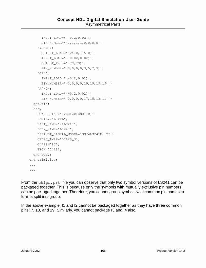
Concept HDL Digital Simulation User GuideAsymmetrical Parts
INPUT_LOAD=’(-0.2,0.02)’;
PIN_NUMBER=’(1,1,1,1,0,0,0,0)’;
’Y0’<0>:
OUTPUT_LOAD=’(24.0,-15.0)’;
INPUT_LOAD=’(-0.02,0.02)’;
OUTPUT_TYPE=’(TS,TS)’;
PIN_NUMBER=’(0,0,0,0,3,5,7,9)’;
’OE0’:
INPUT_LOAD=’(-0.2,0.02)’;
PIN_NUMBER=’(0,0,0,0,19,19,19,19)’;
’A’<0>:
INPUT_LOAD=’(-0.2,0.02)’;
PIN_NUMBER=’(0,0,0,0,17,15,13,11)’;
end_pin;
body
POWER_PINS=’(VCC:20;GND:10)’;
FAMILY=’LSTTL’;
PART_NAME=’74LS241’;
BODY_NAME=’LS241’;
DEFAULT_SIGNAL_MODEL=’SN74LS241N TI’;
JEDEC_TYPE=’DIP20_3’;
CLASS=’IC’;
TECH=’74LS’;
end_body;
end_primitive;
...
...
From the chips.prt file you can observe that only two symbol versions of LS241 can bepackaged together. This is because only the symbols with mutually exclusive pin numbers,can be packaged together. Therefore, you cannot group symbols with common pin names toform a split inst group.
In the above example, I1 and I2 cannot be packaged together as they have three commonpins: 7, 13, and 19. Similarly, you cannot package I3 and I4 also.
January 2002 105 Product Version 14.2

Concept HDL Digital Simulation User GuideAsymmetrical Parts
The schematic with all four symbol versions of LS241 is shown below:
Some sections of the simulation netlist generated for the above schematic is shown below:
...
//
SN74LS241 page2_i1 (._1A1(/* unconnected */),
._1A2(/* unconnected */),
._1A3(/* unconnected */),
._1A4(x5),
._1G_(/* unconnected */),
._1Y1(/* unconnected */),
._1Y2(/* unconnected */),
._1Y3(/* unconnected */),
._1Y4(y3),
._2A1(/* unconnected */),
...
...
._2Y4(/* unconnected */));
January 2002 106 Product Version 14.2

Concept HDL Digital Simulation User GuideAsymmetrical Parts
SN74LS241 page2_i2__1 (._1A1(/* unconnected */),
._1A2(/* unconnected */),
...
...
._2A3(/* unconnected */),
._2A4(x3),
._2G(x4),
...
SN74LS241 page2_i2__2 (._1A1(/* unconnected */),
._1A2(/* unconnected */),
...
._2A3(x8),
._2A4(/* unconnected */),
._2G(x4),
...
._2Y3(y2),
._2Y4(/* unconnected */));
SN74LS241 page2_i2__3 (._1A1(/* unconnected */),
._1A2(/* unconnected */),
...
...
._2A4(/* unconnected */),
._2G(x4),
...
SN74LS241 page2_i2__4 (._1A1(/* unconnected */),
._1A2(/* unconnected */),
...
._2G(x4),
._2Y1(y6),
...
SN74LS241 page2_i3__1 (._1A1(/* unconnected */),
._1A2(/* unconnected */),
...
._1A4(/* unconnected */),
._1G_(x2),
...
January 2002 107 Product Version 14.2

Concept HDL Digital Simulation User GuideAsymmetrical Parts
._1Y4(y5),
._2A1(/* unconnected */),
...
SN74LS241 page2_i3__2 (._1A1(/* unconnected */),
._1A2(/* unconnected */),
._1A3(x1),
._1A4(/* unconnected */),
._1G_(x2),
...
SN74LS241 page2_i3__3 (._1A1(/* unconnected */),
._1A2(/* unconnected */),
...
._1G_(x2),
._1Y1(/* unconnected */),
._1Y2(y1),
._1Y3(/* unconnected */),
._1Y4(/* unconnected */),
...
...
SN74LS241 page2_i3__4 (._1A1(x7),
._1A2(/* unconnected */),
...
._1G_(x2),
...
SN74LS241 page2_i4 (._1A1(/* unconnected */),
._1A2(/* unconnected */),
...
._2A4(x6),
...
._2Y4(y4));
In the netlist shown above, there are four instances of each of I2 and I3. Instances of I3 areSN74LS241 page1_i3__1, SN74LS241 page1_i3__2, SN74LS241 page1_i3__3, andSN74LS241 page1_i3__4. This is because, instance I3 is the non-vectored version ofLS241. It has the HAS_FIXED_SIZE property, with the value 4, attached to it. To know more
January 2002 108 Product Version 14.2

Concept HDL Digital Simulation User GuideAsymmetrical Parts
about the HAS_FIXED_SIZE property see, the Cadence document, PCB SystemsProperties Reference.
On the other hand, symbol instances I1 and I4 do not have the HAS_FIXED_SIZE propertyattached to them. They represent the sizeable version of LS241.
Simulation netlist will change when you add the SPLI_INST or SPLIT_INST_NAMEproperties to the design components. The schematic with SPLIT_INST_NAME = XYZ addedon I1 and I2, and NO_REP_PRIM = TRUE added on I3 is shown below:
Parts of the simulation netlist generated for the above schematic is shown below:
...
...
SN74LS241 XYZ (._1A1(/* unconnected */),
._1A2(/* unconnected */),
._1A3(/* unconnected */),
._1A4(x5),
._1G_({open_p1$1, open_p1$2}),
._1Y1(/* unconnected */),
January 2002 109 Product Version 14.2
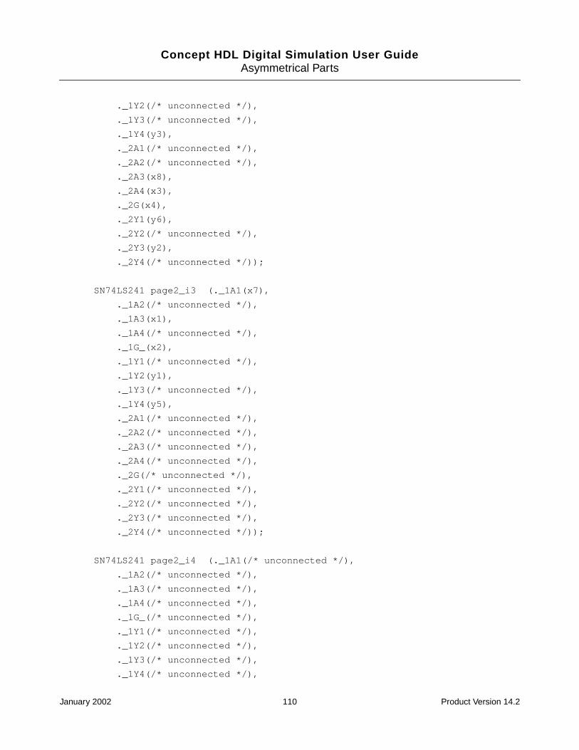
Concept HDL Digital Simulation User GuideAsymmetrical Parts
._1Y2(/* unconnected */),
._1Y3(/* unconnected */),
._1Y4(y3),
._2A1(/* unconnected */),
._2A2(/* unconnected */),
._2A3(x8),
._2A4(x3),
._2G(x4),
._2Y1(y6),
._2Y2(/* unconnected */),
._2Y3(y2),
._2Y4(/* unconnected */));
SN74LS241 page2_i3 (._1A1(x7),
._1A2(/* unconnected */),
._1A3(x1),
._1A4(/* unconnected */),
._1G_(x2),
._1Y1(/* unconnected */),
._1Y2(y1),
._1Y3(/* unconnected */),
._1Y4(y5),
._2A1(/* unconnected */),
._2A2(/* unconnected */),
._2A3(/* unconnected */),
._2A4(/* unconnected */),
._2G(/* unconnected */),
._2Y1(/* unconnected */),
._2Y2(/* unconnected */),
._2Y3(/* unconnected */),
._2Y4(/* unconnected */));
SN74LS241 page2_i4 (._1A1(/* unconnected */),
._1A2(/* unconnected */),
._1A3(/* unconnected */),
._1A4(/* unconnected */),
._1G_(/* unconnected */),
._1Y1(/* unconnected */),
._1Y2(/* unconnected */),
._1Y3(/* unconnected */),
._1Y4(/* unconnected */),
January 2002 110 Product Version 14.2

Concept HDL Digital Simulation User GuideAsymmetrical Parts
._2A1(/* unconnected */),
._2A2(/* unconnected */),
._2A3(/* unconnected */),
._2A4(x6),
._2G(/* unconnected */),
._2Y1(/* unconnected */),
._2Y2(/* unconnected */),
._2Y3(/* unconnected */),
._2Y4(y4));
Note that adding the NO_REP_PRIM = TRUE property on instance I3 merges the netlist forall four sections of I3 into a single netlist. To know more about the NO_REP_PRIM property,see NO_REP_PRIM on page 164.
The netlist now does not have any part by the name SN74LS241 page2_i1 or SN74LS241page2_i2__1. The two parts have been merged into a single instance, SN74LS241 XYZ.This is because the SPLIT_INST_NAME = XYZ property was attached to both the parts.
Working with Wrappers
You can use asymmetrical parts with wrappers also. By default, the parts use the vlog_mapview. In case you want to use wrappers, you will have to add the SIM_BIND_VIEW propertyon the symbol. The value assigned to the SIM_BIND_VIEW property is the name of the viewthat contains wrapper corresponding to the symbol.
In case of split parts, the SIM_BIND_VIEW property should be attached to all the parts in thesplit group. The value assigned to the SIM_BIND_VIEW property should be the view thatcontains wrapper for the combined symbols.
For example, consider that sym1 and sym2 are the two symbols of a part. The wrappercorresponding to sym1 is wrap1 and corresponding to sym2 is wrap2. If you want to simulatethese parts individually, add SIM_BIND_VIEW = wrap1 on sym1 and SIM_BIND_VIEW= wrap2 on sym2.
In case you combine sym1 and symb2 using either the SPLIT_INST_NAME property or theSPLIT_INST and LOCATION properties, you will have to add the SIM_BIND_VIEW = wrap3property both on sym1 and sym2. In this case, the wrap3 view contains the wrappercorresponding to the combined part.
Note: You cannot bind different parts in a split group to different views.
January 2002 111 Product Version 14.2

Concept HDL Digital Simulation User GuideAsymmetrical Parts
January 2002 112 Product Version 14.2

Concept HDL Digital Simulation User Guide
ADialog Box Reference
This section covers various dialog boxes that are opened from Concept HDL digitalsimulation interface.
Choose Simulator
Use this dialog box to select the simulator.
Start Simulator
Use this dialog box to set up and run the simulator you have selected.
Simulator Types
Verilog-XL Selects the Verilog-XL simulator
Third Party Verilog Selects the third-party Verilog simulator
NC (XL-Mode) Allows you to run the NC Verilog simulator to be run in theVerilog-XL mode
NC Verilog Selects the NC Verilog simulator
Leapfrog Selects the Leapfrog simulator
Third Party VHDL Selects the third-party VHDL simulator
NC VHDL Selects the NC VHDL simulator
Setup Invokes the setup dialog box for the selected simulator
OK Saves the settings in the project (.cpm) file and closes thedialog box
Configuration Select the simulation configuration from the drop-down list.
January 2002 113 Product Version 14.2

Concept HDL Digital Simulation User GuideDialog Box Reference
Netlist (Verilog)
Use this tab to specify the options for creating the Verilog netlist.
Run Directory Specify the path to the run directory or click Browse toselect the run directory you want to use for the simulation.
This directory contains files that are created during thesimulation process. These files help you to debug yourdesign. For more information, see Appendix H, “FilesCreated in Run Directory.”
By default, a run directory, sim1, is created in theconfiguration you have selected.
Run Starts the simulation process.
Setup Displays the setup dialog box for the simulator you haveselected.
Cancel Closes the dialog box without saving the changes.
Options
Stop On Netlist Select this check box to stop the simulation process afternetlisting the design.
When you click Run in the Start Simulator dialog box, thedesign will only be netlisted. The simulator will not beinvoked.
Regenerate Netlist Select this check box to generate the netlist for the entiredesign. Optimization is disabled.
Verbose Output Select this check box to display debug messages of thenetlisting process in the Simulation Progress Statuswindow. The debug messages are logged in thedetail.log file located in the run directory.
Uppercase Identifiers Select this check box to write all lowercase identifiers suchas module names, signal names and instance names inuppercase in the netlist.
January 2002 114 Product Version 14.2

Concept HDL Digital Simulation User GuideDialog Box Reference
Position Mapping Select this check box to map Concept HDL pins and modelports by position (based on the port order) in the Verilognetlist.
If this check box is not selected, pins and ports will bemapped by name in the Verilog netlist.
Analyze on Save Select this check box if you want the netlist to be analyzedby ncvlog.exe (NC Verilog compiler) every time you savethe design in Concept HDL.
If the simulator you have selected is NC Verilog, this checkbox is enabled in the Verilog Netlist dialog box that you canaccess from the Output tab of the Concept Options dialogbox. For more information, see the “Netlisting YourDesign” chapter of the Concept HDL User Guide.
Continue on Errors Select this check box if you want to ignore netlisting errorsand simulate the design.
Design Export Select this check box to create a netlist for the entire designin a single file named <design_name>.v. The<design_name>.v file is created in the run directory.
The <design_name>.v file is generated by concatenatingthe multiple netlist files for the hierarchical design and theglobal module.
This option is usually used to generate the netlist forsimulating a design using third-party Verilog simulators.
Generate Compile Script Select this check box if you use any uncompiled libraries inthe design. A compilescript file that lists all thecomponents used in the design is created in the rundirectory when the design is netlisted. Thecompilescript file is executed automatically to compileall the components used in the design.
When the compilescript file is executed, any locallibraries that are uncompiled are automatically compiled.The reference libraries you use in your design will becompiled only if you have write permissions in the referencelibraries.
This check box is enabled only if you are setting up thenetlisting options for the NC Verilog simulator
Note: If any of the libraries you use in your design areuncompiled, the design cannot be compiled.
January 2002 115 Product Version 14.2

Concept HDL Digital Simulation User GuideDialog Box Reference
Regenerate Configuration Select this check box to regenerate the configuration youselected in the Start Simulator dialog box.
A <design_name>.f file is created in the run directory.
This check box is enabled only if you are setting up thenetlisting options for the Verilog-XL simulator.
Check Instance vs Signal When Concept HDL generates the netlist for the design, itwrites each component instance in the netlist as:page<page_number>_<value of PATH property onthe instance>.
For example, if the value of the PATH property of an instanceon page 1 of the schematic is i1, the instance is written inthe netlist as page1_i1.
Select this check box if you want Concept HDL to check ifthe name of any signal on the schematic is the same aspage<page_number>_<value of PATH property onany instance>. If this check box is selected,Concept HDL displays the following error message for everysignal that has the same name aspage<page_number>_<value of PATH property onany instance>:
126 ERROR "Identifier is used as both a PATHvalue and a signal name."
Optimize Unnamed Nets Select the Optimize Unnamed Nets check box when youwant that the simulation netlist should have minimumnumber of alias statements and no unnamed signaldeclarations.
January 2002 116 Product Version 14.2

Concept HDL Digital Simulation User GuideDialog Box Reference
Exclude Libraries If you do not want components in some libraries to benetlisted, specify the list of such libraries.
Specify a library and press Enter to specify each additionallibrary.
This option is provided to prevent Concept HDL fromnetlisting components of libraries
■ to which you do not have write permissions, and
■ to which you have write permissions, but do not want thecomponents to be netlisted.
Note: If you want a component in a library to be netlisted,you must ensure that you have the requisite writepermissions in the library directory.
Max Errors Specify the maximum number of netlisting errors that youwant to allow in the design. The default number is 50.
If the number of netlisting errors in the design exceeds thenumber specified here, Concept HDL will not generate thenetlist.
Verilog
Time Scale Specify the time scale directive for the Verilog module of theschematic. The default value is 1ns/1ns.
The time scale directive specifies the time unit and timeprecision of the modules that follow it. The time unit is theunit of measurement for time values such as the simulationtime and delay values.
January 2002 117 Product Version 14.2

Concept HDL Digital Simulation User GuideDialog Box Reference
Default Net Type Specify the default logic type for all nets in the design. Youcan use any legal Verilog net type, such as WIRE, WAND, andWOR. The default value is WIRE.
The specified net type applies to all drawings in the design.You can override the net type for individual drawings byusing the VLOG_NET_TYPE property on a VERILOG_DECSsymbol.
For more information on the VLOG_NET_TYPE property andVERILOG_DECS symbol, see the Concept HDL UserGuide.
For more information on the Verilog logic types for nets, seePort and Signal Types for Verilog in the Concept HDL UserGuide.
January 2002 118 Product Version 14.2

Concept HDL Digital Simulation User GuideDialog Box Reference
Supply 0 Specify the signal names for the Verilog net type Supply 0.You can specify the name of a component or the value of theHDL_POWER property specified on a component.
■ If you specify the name of a component, all instances ofthe component in the design will be treated asSupply 0 nets.
For example, if you specify GND, all instances of the GNDcomponent in the design will be treated as Supply 0nets.
■ If you specify the value of the HDL_POWER propertyspecified on a component instance, any instance thathas the same HDL_POWER property value will be treatedas a Supply 0 net.
For example, suppose that you have used twoinstances of a component VOLT in a design and havespecified GND as the value of the HDL_POWER propertyon one instance, and +3 as the value of theHDL_POWER property on the second instance. If youspecify GND in the Supply 0 field, only the instance thathas GND as the HDL_POWER property value will betreated as a Supply 0 net. If any other component hasthe same HDL_POWER property value, that componentwill also be treated as a Supply 0 net.
In the above example, if you want to want the instancethat has +3 as the HDL_POWER property value to betreated as a Supply 1 net, specify +3 in the Supply 1field.
■ If you want to specify a bus name in the Supply 0 list,specify only the base name of the bus.
For example, if you want to specify a bus data<3..0>, as Supply 0 add data in the Supply 0 listand not data <3..0>.
Specify a signal name and press Enter to specify eachadditional signal name.
January 2002 119 Product Version 14.2

Concept HDL Digital Simulation User GuideDialog Box Reference
Supply 1 Specify the signal names for the Verilog net type Supply 1.You can specify the name of a component or the value of theHDL_POWER property specified on a component.
■ If you specify the name of a component, all instances ofthe component in the design will be treated asSupply 1 nets.
For example, if you specify VCC, all instances of the VCCcomponent in the design will be treated as Supply 1nets.
■ If you specify the value of the HDL_POWER propertyspecified on a component instance, any instance thathas the same HDL_POWER property value will be treatedas a Supply 1 net.
For example, suppose that you have used twoinstances of a component VOLT in a design and havespecified +3 as the value of the HDL_POWER propertyon one instance, and GND as the value of theHDL_POWER property on the second instance. If youspecify +3 in the Supply 1 field, only the instance thathas +3 as the HDL_POWER property value will betreated as a Supply 1 net. If any other component hasthe same HDL_POWER property value, that componentwill also be treated as a Supply 1 net.In the above example, if you want to want the instancethat has GND as the HDL_POWER property value to betreated as a Supply 0 net, specify GND in theSupply 0 field.
■ If you want to specify a bus name in the Supply 1 list,specify only the base name of the bus.
For example, if you want to specify a bus data<3..0> as Supply 1 add data in the Supply 1 listand not data <3..0>.
Specify a signal name and press Enter to specify eachadditional signal name.
OK Saves the settings in the project (.cpm) file and closes thedialog box.
Cancel Closes the dialog box without saving the changes.
January 2002 120 Product Version 14.2

Concept HDL Digital Simulation User GuideDialog Box Reference
Simulation
Use this tab to set up the options for running the following simulators:
■ Verilog-XL
■ NC Verilog in the Verilog-XL mode
Simulator
Verilog Executable Specify the path to the Verilog-XL executable you want touse or click Browse to select the Verilog executable.
The default Verilog-XL executable is verilog.exe locatedat <your_install_dir>/tools/verilog/bin/verilog.exe.
You can use environment variables to specify the location ofyour Verilog-XL executable. You must add<your_Verilog-XL_install_dir>/tools/lib toyour path.
If you are running NC Verilog in the Verilog-XL mode,specify the path to the ncverilog executable or clickBrowse to select the ncverilog executable. Thencverilog executable is located in the /tools/bindirectory where you have installed the Cadence LDVsoftware.
Delay Mode Select the delay mode for the Verilog-XL simulator as Path,Unit, Distributed, Zero, or None.
Path Select this option to simulate in the path delay mode. In thismode, Verilog-XL derives its timing information from specificblocks. If a module contains a specific block with one ormore module path delays, then all the structural andcontinuous assignment delays within that module, with theexception of trireg charge decay times, are set to zero. Inthe path delay mode, trireg charge decay remains active.The module will simulate with black box timing with onlymodule path delays.
January 2002 121 Product Version 14.2
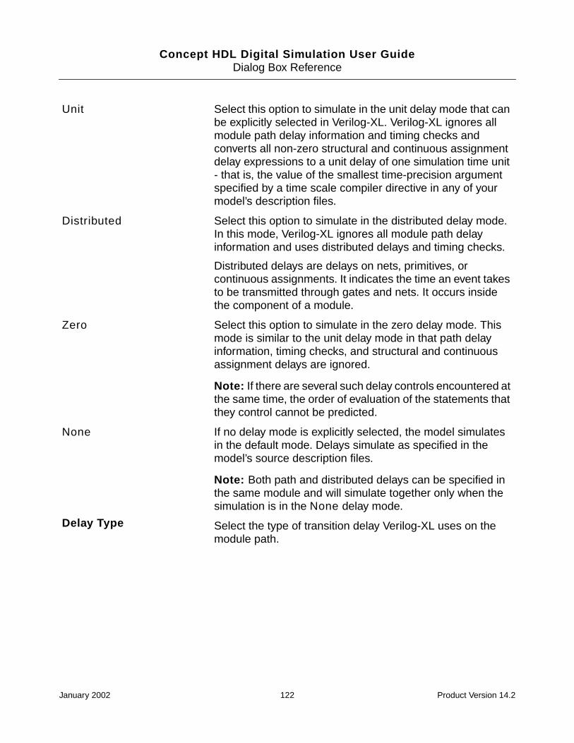
Concept HDL Digital Simulation User GuideDialog Box Reference
Unit Select this option to simulate in the unit delay mode that canbe explicitly selected in Verilog-XL. Verilog-XL ignores allmodule path delay information and timing checks andconverts all non-zero structural and continuous assignmentdelay expressions to a unit delay of one simulation time unit- that is, the value of the smallest time-precision argumentspecified by a time scale compiler directive in any of yourmodel’s description files.
Distributed Select this option to simulate in the distributed delay mode.In this mode, Verilog-XL ignores all module path delayinformation and uses distributed delays and timing checks.
Distributed delays are delays on nets, primitives, orcontinuous assignments. It indicates the time an event takesto be transmitted through gates and nets. It occurs insidethe component of a module.
Zero Select this option to simulate in the zero delay mode. Thismode is similar to the unit delay mode in that path delayinformation, timing checks, and structural and continuousassignment delays are ignored.
Note: If there are several such delay controls encountered atthe same time, the order of evaluation of the statements thatthey control cannot be predicted.
None If no delay mode is explicitly selected, the model simulatesin the default mode. Delays simulate as specified in themodel’s source description files.
Note: Both path and distributed delays can be specified inthe same module and will simulate together only when thesimulation is in the None delay mode.
Delay Type Select the type of transition delay Verilog-XL uses on themodule path.
January 2002 122 Product Version 14.2
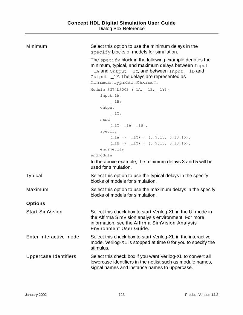
Concept HDL Digital Simulation User GuideDialog Box Reference
Minimum Select this option to use the minimum delays in thespecify blocks of models for simulation.
The specify block in the following example denotes theminimum, typical, and maximum delays between Input_1A and Output _1Y, and between Input _1B andOutput _1Y. The delays are represented asMinimum:Typical:Maximum.
Module SN74LS00P (_1A, _1B, _1Y);
input_1A,
_1B;
output
_1Y;
nand
(_1Y, _1A, _1B);
specify
(_1A => _1Y) = (3:9:15, 5:10:15);
(_1B => _1Y) = (3:9:15, 5:10:15);
endspecify
endmodule
In the above example, the minimum delays 3 and 5 will beused for simulation.
Typical Select this option to use the typical delays in the specifyblocks of models for simulation.
Maximum Select this option to use the maximum delays in the specifyblocks of models for simulation.
Options
Start SimVision Select this check box to start Verilog-XL in the UI mode inthe Affirma SimVision analysis environment. For moreinformation, see the Affirma SimVision AnalysisEnvironment User Guide.
Enter Interactive mode Select this check box to start Verilog-XL in the interactivemode. Verilog-XL is stopped at time 0 for you to specify thestimulus.
Uppercase Identifiers Select this check box if you want Verilog-XL to convert alllowercase identifiers in the netlist such as module names,signal names and instance names to uppercase.
January 2002 123 Product Version 14.2

Concept HDL Digital Simulation User GuideDialog Box Reference
Library
Use this tab to setup the Verilog model libraries.
Compile Only Select this check box to stop Verilog-XL after the design iscompiled. This is useful when you want to check if allmodels are available and accessed correctly.
Additional Options
Command File Specify the path to the command file that contains thecommand-line options for Verilog-XL.
Command Line Specify command line options other than those defined inthe selected command file.
OK Saves the settings in the project (.cpm) file and closes thedialog box.
Cancel Closes the dialog box without saving the changes.
Library Extensions Specify the extensions of Verilog model library file namesthat Verilog-XL has to search for. Type+.<file_extension> to add a file extension. Forexample, to add a file extension .vxl, type +.vxl.
If you have specified a directory containing Verilog modellibraries, Verilog-XL searches for only the model library filesin the directory that have the specified extension. Forexample if you have specified the file extension .vxl,Verilog-XL searches for all files in the library directory thathave the .vxl extension.
The default extensions of Verilog model library file namesthat Verilog-XL searches for are .v and .verilog.
January 2002 124 Product Version 14.2

Concept HDL Digital Simulation User GuideDialog Box Reference
Stimulus (Verilog)
Use this tab to specify the options for providing a stimulus in the following simulators:
■ Verilog-XL simulator
■ NC Verilog simulator
■ NC Verilog simulator in the Verilog-XL mode
Path Click on the drop-down and select:
■ Directories, to specify the path to the directoriescontaining Verilog model libraries.
■ Files, to specify the path to Verilog model libraries.
A list box is displayed for the selected option.
■ Click to add an element. Enter the path to theelement or click the browse button to select the element.See also Using the vlog_model_path.txt file to specifyVerilog model libraries on page 14.
■ Click to delete the selected element.
■ Click to move the selected element one level up.
■ Click to move the selected element one level down.
The order in which the elements are listed determines thesearch order for Verilog modules in the design.
OK Saves the settings in the project (.cpm) file and closes thedialog box.
Cancel Closes the dialog box without saving the changes.
Testbench
Generate Testbench Select this option if you want to generate the testbench. Youcan specify the details to generate the Verilog testbench filethat instantiates the design under test with its port list. Theport list contains interface signals of the design.
January 2002 125 Product Version 14.2

Concept HDL Digital Simulation User GuideDialog Box Reference
Stimulus File Only Select this option if you want to use the stimulus file.
This option is enabled only if you are setting up thetestfixture for the Verilog-XL simulator.
Note: Cross probing will not work if you use Stimulus FileOnly instead of Include Testbench if you have a testbench.
Include Testbench Select this option if you want to include a testbench.
Note: To perform cross probing you must use the IncludeTestbench option if you have a testbench instead of theStimulus File Only option.
None Select this if you do not want any testbench task.
Details
Stimulus File Specify the path to the stimulus file if you have selected theGenerate Testbench or Stimulus File Only option.
Design Instance Specify the instantiated name of the design under test if youhave selected the Generate Testbench option. The defaultname is top.
Testbench File Specify the path to the testbench file to be included, if youhave selected the Include Testbench option.
Generate Click this button to generate the specified tesbench file.
Edit Click this button to edit the specified testbench file. Thetestbench file is opened in a text editor.
Note: The default text editor is vi in UNIX and WordPad inWindows NT. You can change the default text editor in theTools tab of Project Setup. For more information, see theProject Setup Online Help.
Time Scale Specify the time scale directive for the testbench module ifyou have selected the Generate Testbench option.
Example: 1ns/100ps
OK Saves the settings in the project (.cpm) file and closes thedialog box.
Cancel Closes the dialog box without saving the changes.
January 2002 126 Product Version 14.2

Concept HDL Digital Simulation User GuideDialog Box Reference
Allegro SDF (Verilog)
Use this dialog box set up SDF annotation options for the following simulators:
■ Verilog-XL
■ NC Verilog
Perform SDF Annotation Select this check box if you want to perform SDF annotation.You can now specify the details of the Allegro SDF file to beused for SDF annotation.
Only if you select this check box are the remaining optionsare enabled.
Note: FPGA/CPLD SDF files are not to be specified here.
Allegro SDF File Specify the path to the SDF file generated by Allegro thatyou want to use during simulation.
The SDF annotator reads this SDF file.
Scope Specify the module instance.
The SDF Annotator uses the hierarchy level of this instancefor running the annotation.
Delay Type Select the appropriate delay type to indicate how the SDFAnnotator should annotate delay values.
Minimum Annotate the minimum delay value.
Maximum Annotate the maximum delay value.
Typical Annotate the typical delay value.
Tool Control Annotate with the delay type selected in the Simulation tab.
Scale Type Select the appropriate scale type to indicate how the SDFAnnotator should scale the timing data from the SDF file.
From Minimum Scale the minimum timing data from the SDF file.
From Typical Scale the typical timing data from the SDF file.
From Maximum Scale the maximum timing data from the SDF file.
From MTM Scale the Minimum To Maximum timing data from the SDFfile.
January 2002 127 Product Version 14.2

Concept HDL Digital Simulation User GuideDialog Box Reference
VHDL Netlist
Use this dialog box to set VHDL netlisting options.
Scale Factors Specify the set of three real number multipliers in the form ofmin_mult:typ_mult:max_mult that you want to scaleyour delay values. The SDF annotator uses these to scalethe minimum, typical, and maximum timing data from theSDF file before they are annotated to the Verilog simulator.
Default is 1:1:1
Example: 1.0:2.0:1.0
Generate SDF BackAnnotation Log
Select this check box to generate the log file duringannotation.
The log file is generated in the run directory.
The SDF Annotator writes status information, warnings, anderror messages to the log file during the annotation process.These messages also include the configuration of theannotator, assumptions made during annotation, andwarnings or errors due to inconsistencies found duringannotation. The SDF Annotator also prints warning anderror messages to a standard output.
OK Saves the settings in the project (.cpm) file and closes thedialog box.
Cancel Closes the dialog box without saving the changes.
Options
Stop On Netlist Select this check box to stop the simulation process afternetlisting the design.
When you click Run in the Start Simulator dialog box, thedesign will only be netlisted. The simulator will not beinvoked.
Regenerate Netlist Select this check box to generate the netlist for the entiredesign. Optimization is disabled.
January 2002 128 Product Version 14.2

Concept HDL Digital Simulation User GuideDialog Box Reference
Verbose Output Select this check box to display debug messages of thenetlisting process in the Details window. The debugmessages are logged in the detail.log file located in therun directory.
Strict Entity Check Select this check box to enable strict error checking forVHDL entities. Concept HDL compares the port andparameter definitions of a symbol with the entity declarationin the library. In other words, Concept HDL comparesinstance properties and symbol properties (like theVHDL_MODE property). If they are not consistent, it reportswarnings and errors.
If this check box is not selected, a loose entity check will beperformed. If there are any inconsistencies, only errors arereported. Warnings are not reported.
Position Mapping Select this check box to map Concept HDL pins and modelports by position (based on the port order) in the VHDLnetlist.
If this check box is not selected, pins and ports will bemapped by name in the VHDL netlist.
Analyze on Save Select this check box if you want the netlist to be analyzedby ncvhdl.exe (NC VHDL compiler) or cv.exe (Leapfrogcompiler) every time you save the design in Concept HDL.
If the simulator you have selected is NC VHDL or Leapfrog,this check box is enabled in the Verilog Netlist dialog boxthat you can access from the Output tab of the ConceptOptions dialog box. For more information, see the“Netlisting Your Design” chapter of the Concept HDLUser Guide.
If the NC VHDL simulator is selected, the netlist is analyzedby ncvhdl.exe. If the Leapfrog simulator is selected, thenetlist is analyzed by cv.exe.
Continue on Errors Select this check box if you want to ignore netlisting errorsand simulate the design.
January 2002 129 Product Version 14.2

Concept HDL Digital Simulation User GuideDialog Box Reference
Design Export Select this check box to create a netlist for the entire designin a single file named <design_name>.vhd. The<design_name>.vhd file is created in the run directory.
The <design_name>.vhd file is generated byconcatenating multiple netlist files for the hierarchical designand the global module.
Generate Compile Script Select this check box if you use any uncompiled libraries inthe design. A compilescript file that lists all thecomponents used in the design is created in the rundirectory when the design is netlisted. Thecompilescript file is executed automatically to compileall the components used in the design.
When the compilescript file is executed, any locallibraries that are uncompiled are automatically compiled.The reference libraries you use in your design will becompiled only if you have write permissions in the referencelibraries.
This check box is enabled only if you are setting up thenetlisting options for the NC Verilog simulator
Note: If any of the libraries you use in your design areuncompiled, the design cannot be compiled.
Check Instance vs Signal When Concept HDL generates the netlist for the design, itwrites each component instance in the netlist as:page<page_number>_<value of PATH property onthe instance>.
For example, if the value of the PATH property of an instanceon page 1 of the schematic is i1, the instance is written inthe netlist as page1_i1.
Select this check box if you want Concept HDL to check ifthe name of any signal on the schematic is the same aspage<page_number>_<value of PATH property onany instance>. If this check box is selected,Concept HDL displays the following error message for everysignal that has the same name aspage<page_number>_<value of PATH property onany instance>:
126 ERROR "Identifier is used as both a PATHvalue and a signal name."
January 2002 130 Product Version 14.2
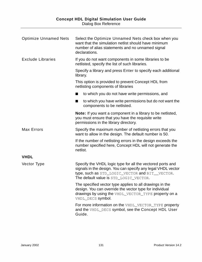
Concept HDL Digital Simulation User GuideDialog Box Reference
Optimize Unnamed Nets Select the Optimize Unnamed Nets check box when youwant that the simulation netlist should have minimumnumber of alias statements and no unnamed signaldeclarations.
Exclude Libraries If you do not want components in some libraries to benetlisted, specify the list of such libraries.
Specify a library and press Enter to specify each additionallibrary.
This option is provided to prevent Concept HDL fromnetlisting components of libraries
■ to which you do not have write permissions, and
■ to which you have write permissions but do not want thecomponents to be netlisted.
Note: If you want a component in a library to be netlisted,you must ensure that you have the requisite writepermissions in the library directory.
Max Errors Specify the maximum number of netlisting errors that youwant to allow in the design. The default number is 50.
If the number of netlisting errors in the design exceeds thenumber specified here, Concept HDL will not generate thenetlist.
VHDL
Vector Type Specify the VHDL logic type for all the vectored ports andsignals in the design. You can specify any legal VHDL vectortype, such as STD_LOGIC_VECTOR and BIT__VECTOR.The default value is STD_LOGIC_VECTOR.
The specified vector type applies to all drawings in thedesign. You can override the vector type for individualdrawings by using the VHDL_VECTOR_TYPE property on aVHDL_DECS symbol.
For more information on the VHDL_VECTOR_TYPE propertyand the VHDL_DECS symbol, see the Concept HDL UserGuide.
January 2002 131 Product Version 14.2

Concept HDL Digital Simulation User GuideDialog Box Reference
Scalar Type Specify the VHDL logic type for all scalar ports and signalsin the design. You can specify any legal VHDL scalar type,such as STD_LOGIC and BIT. The default value isSTD_LOGIC.
The specified scalar type applies to all drawings in thedesign. You can override the scalar type for individualdrawings by using the VHDL_SCALAR_TYPE property on aVHDL_DECS symbol.
For more information on the VHDL_SCALAR_TYPE propertyand the VHDL_DECS symbol, see the Concept HDL UserGuide.
Libraries Specify the names of the libraries that are to be used inVHDL library clauses in the VHDL entity and architecturetext generated from the schematic. There is no limit on thenumber of libraries you can add.
If you do not specify a library, IEEE will be used as thedefault library. If you need to use the IEEE library along withother libraries, you must explicitly add the IEEE library.
You can also add libraries for a drawing by using theLIBRARY property on a VHDL_DECS symbol. In the VHDLentity and architecture text generated from the schematic,the libraries on the symbol will be appended to the list oflibraries you specify here.
Packages Specify the names that are to be used in VHDL use clausesin the VHDL entity and architecture text generated from theschematic. There is no limit on the number of use clausesyou can add.
If you do not specify any use clauses,IEEE.STD_LOGIC_1164.ALL will be used as the default.The default use clauses (IEEE.STD_LOGIC_1164.ALL) isnot used if you specify any other use clause. If you need touse the IEEE.STD_LOGIC_1164.ALL use clauses alongwith other use clauses, you must explicitly add theIEEE.STD_LOGIC_1164.ALL use clauses.
You can also add use clauses for a drawing by using theUSE property on a VHDL_DECS symbol. In the VHDL entityand architecture text generated from the schematic, the useclauses on the symbol will be appended to the list of useclauses you specify here.
January 2002 132 Product Version 14.2

Concept HDL Digital Simulation User GuideDialog Box Reference
Leapfrog: Simulation
Use this dialog box to set the options for invoking the Leapfrog Notebook.
OK Saves the settings in the project (.cpm) file and closes thedialog box.
Cancel Closes the dialog box without saving the changes.
Notebook
Invoke Leapfrog Notebook Select this check box if you want to start the LeapfrogNotebook when you run the simulation.
Notebook Options Specify the command-line options to run the LeapfrogNotebook. For more information, see the LeapfrogNotebook User Guide.
Flow Options Select the options to specify whether the design should becompiled, elaborated, or simulated in the Leapfrog simulatorevery time you run the simulation.
Compile Select this check box if you want to compile your designusing the Leapfrog compiler (cv) every time you run thesimulation.
Elaborate Select this check box if you want to elaborate your designusing the Leapfrog elaborator (ev) every time you run thesimulation.
Simulate Select this check box if you want to simulate your designusing the Leapfrog simulator (sv) every time you run thesimulation. The simulator will not be invoked if this checkbox is not selected.
Configuration Options
Generate Configuration Select this option to run the Hierarchy Editor and generatethe configuration cfg_vhdl.
Library Name Specify the name of the configuration library.
Cell Name Specify the name of the configuration cell.
Include Configuration Select this option to include the configuration in the compilescript.
January 2002 133 Product Version 14.2

Concept HDL Digital Simulation User GuideDialog Box Reference
Leapfrog: Compile
Use this dialog box to set Leapfrog compiler (cv) and VITAL options.
OK Saves the settings in the project (.cpm) file and closes thedialog box.
Cancel Closes the dialog box without saving the changes.
Compiler Options
Produce Source Listing Select this check box to generate a VHDL source listing withstandard error messages inserted at the point of the error.This listing file has the extension .lst. If the input is fromthe standard input, the file is named as stdin.lst.
Select the Produce Extended Listing check box to includeextended error messages in the VHDL source listing.
Produce Extended Listing Select this check box to generate a VHDL source listing withextended error messages.
If the Produce Source Listing check box is also selected,the compiler includes extended error messages, as well asstandard error messages.
Display Messages Select this check box to display informational messagesduring compilation. The messages summarize errors andwarnings accumulated during the analysis of each VHDLsource file.
This option is useful for compiling a large number of VHDLsource files. The messages confirm the completion of thecompilation process.
Exclude DebugInformation
Select this check box to disable bounds checks andunderflow or overflow checks during compilation.
If you do not need these checks, you can increasecompilation speed by disabling either one or both checks.
Disable Bounds Checks Select this check box to disable bounds checks duringcompilation.
Disable Under/Over Check Select this check box to disable underflow or overflowchecks during compilation.
January 2002 134 Product Version 14.2

Concept HDL Digital Simulation User GuideDialog Box Reference
Other Options Specify any other legal Leapfrog compiler (cv) option.
For a list of cv options, see the “cv Command–LineFormat” section in Chapter 3, “Compilation and the cvCommand” of the Leapfrog VHDL Simulator Reference.
Vital Options
Disable RTL Acceleration Select this check box to disable the optimization of IEEE1164 data types and functions.
Disable Vital Acceleration Select this check box to suppress acceleration and VITALlevel-1 compliance checks. Use this option if you require theregular Leapfrog debug capability for a VITAL model.
If you select this check box, the Disable Timing Checks,Enable Name Checks, Disable Messages, and DisableX Generation options have no effect.
Disable Timing Checks Select this check box to suppress all timing checks, periodchecks, and recovery removal checks in level-1 compliantarchitectures during compilation.
This option works only if the Disable Vital Accelerationcheck box is not selected.
Disable Messages Select this check box to suppress message generation fromtiming checks and path delays during VITAL acceleration.
This option works only if the Disable Vital Accelerationcheck box is not selected.
Enable Name Checks Select this check box to perform name checks for the use ofgenerics and signals inside a VITAL model. These checksare not required by VITAL but are recommended. By default,name checks are disabled.
This option works only if the Disable Vital Accelerationcheck box is not selected.
Disable X Generation Select this check box to suppress message generation fromtiming checks and path delays during VITAL acceleration.
This option works only if the Disable Vital Accelerationcheck box is not selected.
OK Saves the settings in the project (.cpm) file and closes thedialog box.
Cancel Closes the dialog box without saving the changes.
January 2002 135 Product Version 14.2

Concept HDL Digital Simulation User GuideDialog Box Reference
Leapfrog: Elaborate
Use this dialog box to set Leapfrog elaborator (ev) and VITAL options.
Elaborator Options
Display Messages Select this check box to display messages about theelaboration process as it occurs. The messages includesummaries of the processes and signals in the simulation,as well as the name of the simulation data file. Thisinformation is desirable when ev computes the defaultsimulation name.
Preserve Resolution Select this check box to generate reflexive signal calls to theresolution function. Selecting this option reduces simulationperformance.
For information on reflexive signals, see the “The ReflexiveProperty of Resolved Signals” section in Chapter 4,“Elaboration and the ev Command” of the LeapfrogVHDL Simulator Reference.
Compatible Mode Select this check box to specify the vendor compatibilitymode in which the elaborator accepts several commonvariations in VHDL constructs.
For more information, see “The -compatibility Option”section in Appendix A, “Leapfrog Simulator and LRMCompliance” of the Leapfrog VHDL SimulatorReference.
Exclude DebugInformation
Select this check box to reduce the simulation snapshot sizeby omitting debug information.
Update out-of-dateDesigns
Select this check box to check the time stamp of thesimulation snapshot to see whether it is more recent thanany of the design units it contains. If any design unit has amore recent time stamp than the simulation snapshot, theelaborator updates the snapshot by recompiling all designunits that are not up-to-date.
January 2002 136 Product Version 14.2

Concept HDL Digital Simulation User GuideDialog Box Reference
Check for out-of-dateSources
Select this check box to check the source files associatedwith the unit being elaborated during the update. If a sourcefile that is more recent than the compiled design unit exists,the elaborator compiles the source file and includes itsdesign unit in the snapshot.
This option is enabled only if the Update out-of-dateDesigns check box is selected.
Other Options Specify any other legal Leapfrog elaborator (ev) option.
For a list of ev options, see the “ev Command–LineFormat” section in Chapter 4, “Elaboration and the evCommand” of the Leapfrog VHDL Simulator Reference.
Disable Input Port Delays Select this check box if you want the elaborator to ignore thelumped interconnect delays specified on input ports in theWIREDDELAY block. Use this option to speed the simulationof circuits when the input port delays should be ignored.
By default, this option causes the delayed signal to becollapsed to the port unless you specify the -nocollapseoption.
Unit Delay Gates Select this check box to convert the delays on all primitiveinstances to the minimum unit of time used in the model.
Vital Options
Simulation Units Select this check box to elaborate the design using a unit oftime you specify. Enter a time value in the first field and clickon the drop-down list in the second field to select the timeunit type (us, ns, ps, or fs).
January 2002 137 Product Version 14.2

Concept HDL Digital Simulation User GuideDialog Box Reference
Leapfrog: Simulate
Use this dialog box to set Leapfrog simulator (sv) and VITAL options.
Simple Delay Gates Click on the drop-down list to specify the delay value.
All input-output delay values on any particular primitiveinstance are considered to have the same value.
■ The value default specifies that the default delayvalue is the average of all delays.
■ The value max specifies that all delays take the value ofthe maximum delay.
■ The value min specifies that all delays take the value ofthe minimum delay.
■ The value average specifies that all delays take theaverage value of all the individual I/O delays for thatprimitive instance.
OK Saves the settings in the project (.cpm) file and closes thedialog box.
Cancel Closes the dialog box without saving the changes.
Simulator Options
Display Messages Select this check box to display messages about thesimulation process as it occurs.
Compatible Mode Select this check box to enable the vendor compatibilitymode, which allows the simulator to accept several commonvariations in VHDL constructs.
For more information, see “The -compatibility Option”section in Appendix A, “Leapfrog Simulator and LRMCompliance” of the Leapfrog VHDL SimulatorReference.
Update Out-of-dateDesigns
Select this check box to update all design units just beforethe simulation is invoked so that design units are up to datewith the snapshot.
January 2002 138 Product Version 14.2

Concept HDL Digital Simulation User GuideDialog Box Reference
VHDL Stimulus
Use this dialog box to provide a stimulus to your design.
Check for out-of-dateSources
Select this check box to check the source files associatedwith the design unit being simulated. If a source file existsthat is more recent than the compiled design unit, thesimulator compiles and elaborates the source file into thesnapshot.
This option is enabled only if the Update out-of-dateDesigns check box is selected.
Other Options Specify any other legal Leapfrog compiler (sv) option.
For a list of sv options, see the “sv Invocation Options”section in Chapter 5, “The Leapfrog VHDL Simulator andthe sv Command” of the Leapfrog VHDL SimulatorReference.
OK Saves the settings in the project (.cpm) file and closes thedialog box.
Cancel Closes the dialog box without saving the changes.
Testbench
Generate Testbench Select this option if you want to generate a testbench thatinstantiates the top level module with a port list. All theinterface signals in your design are listed in the port list. Youhave to regenerate the testbench for simulation if the portlist changes.
Specify the details in the Input Design and Design Unitfields, and click Generate to generate the testbench.
Include Testbench Select this option if you want to include a testbench fileduring VHDL simulation.
Specify the name of the testbench file in the Design Unitfield.
None Select this option if you do not want to include or generateany testbench file.
Details
January 2002 139 Product Version 14.2

Concept HDL Digital Simulation User GuideDialog Box Reference
Allegro SDF (VHDL)
Use this dialog box to do set SDF annotation options for the following simulators:
■ Leapfrog VHDL simulator
■ NC VHDL simulator
Input Design Specify the VHDL entity architecture for which you want togenerate the testbench file in the format lib.cell:viewor lib.cell.
Overwrite Select this check box if you want to overwrite the testbenchfile that exists in the same path.
Design Unit Specify the name of the testbench file in the formatlib.cell:view.
Generate Click this button to generate the testbench file.
Edit Click this button to edit the specified testbench file. Thetestbench file is opened in a text editor. You can specify thestimulus for the design.
Note: The default text editor is vi in UNIX and WordPad inWindows NT. You can change the default text editor in theTools tab of Project Setup. For more information, see theProject Setup Online Help.
OK Saves the settings in the project (.cpm) file and closes thedialog box.
Cancel Closes the dialog box without saving the changes.
Perform SDF Annotation Select this check box if you want to perform SDF annotation.You can now specify the details of the Allegro SDF file toperform annotation.
Only if you select this check box are the remaining optionsenabled.
Allegro SDF File Specify the name of the SDF file generated by Allegro touse during simulation. This file is processed and convertedto a format that is used by Leapfrog and NC VHDL toperform SDF back annotation.
January 2002 140 Product Version 14.2

Concept HDL Digital Simulation User GuideDialog Box Reference
NC Verilog: Simulation
Output SDF Directory Specify the directory where the processed SDF file will bestored. This file is used by Leapfrog and NC VHDL toperform SDF annotation.
Scope Specify the module instance.
The SDF annotator uses the hierarchy level of this instancefor running the annotation.
Specify the top level module to which this delay applies. Forexample, if the testfixture module is called testbench andthe instance name of the Concept HDL design is top, youneed to enter testbench.top in this field.
Delay Type Select the appropriate delay type to indicate how the SDFAnnotator should annotate delay values to the simulator.
Minimum Annotates the minimum delay value.
Maximum Annotates the maximum delay value.
Typical Annotates the typical delay value.
Tool Control Annotates with the delay type selected in the Leapfrog:Simulation dialog box.
Generate SDF BackAnnotation Log
Select this check box to generate the SDF annotation log.
The log file is generated in the run directory.
The SDF Annotator writes status information, warnings, anderror messages to the log file during the annotation process.These messages also include the configuration of theannotator, assumptions made during annotation, andwarnings or errors due to inconsistencies found duringannotation. The SDF Annotator also prints warning anderror messages to a standard output.
OK Saves the settings in the project (.cpm) file and closes thedialog box.
Cancel Closes the dialog box without saving the changes.
Options
January 2002 141 Product Version 14.2

Concept HDL Digital Simulation User GuideDialog Box Reference
hdl.var file Specify the path to the hdl.var file.
If you do not specify the path to the hdl.var file, a defaulthdl.var file will be created in the run directory.
Log Directory Enter the path to the directory where you want the followinglog files to be created:
■ ncvlog.log, which contains the messages loggedwhen the design is compiled.
■ ncelab.log, which contains the messages loggedwhen the design is elaborated.
■ ncsim.log, which contains the messages loggedwhen the design is simulated.
By default, the log files are created in the run directory.
Flow Options Select the options to control whether the design should becompiled, elaborated, or simulated in the NC Verilogsimulator every time you run the simulation.
Compile Select this check box if you want to compile the design everytime you run the simulation. The ncvlog program is used tocompile the design.
Enter additional command-line options for ncvlog in theCmd Options field.
Elaborate Select this check box if you want to elaborate the designevery time you run the simulation. The ncelab program isused to elaborate the design.
Enter additional command-line options for ncelab in theCmd Options field.
Simulate Select this check box if you want to simulate the design inthe NC Verilog simulator every time you run the simulation.The simulator will not be invoked if this check box is notselected.The ncsim program is used to simulate the design.
Enter additional command-line options for ncsim in theCmd Options field.
Start SimVision Select this check box to start NC Verilog in the UI mode inthe Affirma SimVision analysis environment. For moreinformation, see the Affirma SimVision AnalysisEnvironment User Guide.
January 2002 142 Product Version 14.2

Concept HDL Digital Simulation User GuideDialog Box Reference
NC VHDL: Simulation
Enter Interactive mode Select this check box to start NC Verilog in the interactivemode. NC Verilog is stopped at time 0 for you to specify thestimulus.
OK Saves the settings in the project (.cpm) file and closes thedialog box.
Cancel Closes the dialog box without saving the changes.
Options
hdl.var file Specify the path to the hdl.var file.
If you do not specify the path to the hdl.var file, a defaulthdl.var file will be created in the run directory.
Log Directory Select the Log Path check box and enter the path to thelocation where you want the following log files to be created:
■ ncvhdl.log, which contains the messages loggedwhen the design is compiled.
■ ncelab.log, which contains the messages loggedwhen the design is elaborated.
■ ncsim.log, which contains the messages loggedwhen the design is simulated.
By default the log files are created in the run directory.
Flow Options Select the options to specify whether the design should becompiled, elaborated, or simulated in the NC VHDLsimulator every time you run the simulation.
Compile Select this check box if you want to compile the design everytime you run the simulation. The ncvhdl program is used tocompile the design.
Enter additional command-line options for ncvhdl in theCmd Options field.
January 2002 143 Product Version 14.2

Concept HDL Digital Simulation User GuideDialog Box Reference
Elaborate Select this check box if you want to elaborate the designevery time you run the simulation. The ncelab program isused to elaborate the design.
Enter additional command-line options for ncelab in theCmd Options field.
Simulate Select this check box if you want to simulate the design inthe NC VHDL simulator every time you run the simulation.The simulator will not be invoked if this check box is notselected. The ncvlog program is used to simulate thedesign.
Enter additional command-line options for ncsim in theCmd Options field.
Start SimVision Select this check box to start NC Verilog in the UI mode inthe Affirma SimVision analysis environment. For moreinformation, see the Affirma SimVision AnalysisEnvironment User Guide.
Enter Interactive mode Select this check box to start NC Verilog in the interactivemode.
Configuration Options
Generate Configuration Select this option to run the Hierarchy Editor and togenerate the configuration cfg_vhdl.
Library Name Specify the name of the configuration library.
Cell Name Specify the name of the configuration cell.
Include Configuration Select this option to include the configuration in the compilescript.
OK Saves the settings in the project (.cpm) file and closes thedialog box.
Cancel Closes the dialog box without saving the changes.
January 2002 144 Product Version 14.2

Concept HDL Digital Simulation User Guide
BRunning NC Verilog and NC VHDLSimulators from the Command Line
You can use the ncrun command to run the NC Verilog and NC VHDL simulators from thecommand line.
Syntax
ncrun -proj <projectname.cpm> [options]
Options Description
-cdslib <cds.lib file path> Specify the path to the cds.lib file.
-compile <y|n> Specify if you want to compile the design.
-config <root drawing view> Specify the configuration in the root drawingview that you want to use for simulation.
-elaborate <y|n> Specify if you want to elaborate the design.
-genconfig <y|n> Specify if you want to re-generate theconfiguration you specified with the-config option.
-gui <y|n> Specify if you want to run NC Verilog or NCVHDL in the Affirma SimVision analysisenvironment. For more information, see theAffirma SimVision AnalysisEnvironment User Guide.
-hdlvar <hdl.var file path> Specify the path to the hdl.var file.
-run_dir <path to run directory> Specify the path to the run directory for thesimulation.
January 2002 145 Product Version 14.2

Concept HDL Digital Simulation User GuideRunning NC Verilog and NC VHDL Simulators from the Command Line
-save_options Saves all other specified command lineoptions in the project file (.cpm) file.
For example, if you run the followingcommand:
ncrun -proj count.cpm –compile n–elaborate n -save_options
The options specifying that the designshould not be compiled or elaborated whenyou run the simulation are saved in theproject file (count.cpm). The next time yourun the simulation from the command lineor from the Concept HDL Digital SimulationInterface, the design will not be compiled orelaborated.
-sdf <path to Allegro SDF file> Specify the path to the Allegro SDF file youwant to use for performing SDF annotation.
-sim <ncvlog|ncvhdl> Specify if you want to use the NC Verilog orNC VHDL simulator for simulating thedesign.
-simulate <y|n> Specify if you want to simulate the design.
-stim_file <path to stimulusfile>
Specify the path to the stimulus file youwant to use for simulating the design.
Options Description
January 2002 146 Product Version 14.2

Concept HDL Digital Simulation User GuideRunning NC Verilog and NC VHDL Simulators from the Command Line
-tbn Specify the path to the testbench module orstimulus file you want to use, as below:
■ For NC Verilog, if you want to simulatethe design using a testbench, specifythe name of the testbench module. Thedefault testbench module istestfixture
For NC Verilog, If you want to simulatethe design using a stimulus file, specifythe path to stimulus file in thelib.cell:view format. The defaultstimulus file path is<worklib>.testfixture:inca
■ For NC VHDL, specify the path to thetestbench in the lib.cell:viewformat.
-tf <path to testfixture> Specify the path to the testfixture you wantto use.
Options Description
January 2002 147 Product Version 14.2

Concept HDL Digital Simulation User Guide
CSimulation Configurations
When you create a new project, four configurations are created automatically, one for eachexpansion type. These are
■ cfg_package for physical layout
■ cfg_pic for PIC configurations
■ cfg_verilog for Verilog simulation
■ cfg_vhdl for VHDL simulation
The default configurations are present as views of the top level design. Each configuration isa view of the design and is located in the design directory (cell) at the same level as otherviews such as schematic, symbol, and chips. You can have several configurations for adesign.
Each configuration view contains a configuration file (expand.cfg). The expand.cfg filespecifies the selection of views that determine how a design is expanded and simulated. Theexpand.cfg file has:
■ View List that specifies the various views in order of preference for configurations.
■ Cell Binding Statements that specifies forced binding for all instances of aparticular cell overwriting the selection specified by the View List.
■ Instance Binding Statements that specifies forced binding for individual instancesof a particular cell overwriting the selection specified by the View List or CellBinding Statements.
Note: You can specify Instance Binding Statements without Cell BindingStatements.
For hierarchical designs, a complete configuration of a sub design can be treated as a view.In such cases, a view should contain a file named expand.cfg (for expansion configuration).You can select this view for simulation using the configuration at the top level. A view may notcontain both a design description and a configuration.
January 2002 148 Product Version 14.2

Concept HDL Digital Simulation User GuideSimulation Configurations
Example
Suppose you want to design a full adder using half adders. The top level schematic for thedesign will have 2 half adder instances. You can descend down the half adder to view theschematic for the half adder.
You can use this configuration name in the View List of your top level configuration as:
viewlist cfg_half_adder, vlog_model, hw_model, swift_model
This is a useful feature if you want to use sub designs to work as required under specificconfigurations, and you do not want the configuration of the sub design to be changed by yourtop level View List.
Creating a Configuration
You can use the Hierarchy Editor tool to create a new Verilog or VHDL simulationconfiguration.
To create a new configuration, do the following:
1. From Project Manager or Concept HDL, choose Tools > Hierarchy Editor.
The Hierarchy Editor window appears.
2. Choose File > New.
The New Configuration dialog box appears.
3. Click the Use Template button.
The Use Template dialog box appears.
4. From the Name field, choose Other.
5. In the From File field, type
❑ <your_install_dir>/share/cdssetup/hiereditor/pcb_verilog
if you are creating a Verilog simulation configuration.
❑ <your_install_dir>/share/cdssetup/hiereditor/pcb_vhdl
if you are creating a VHDL simulation configuration.
6. Click OK.
The New Configuration dialog box appears. The fields in the New Configurationdialog box are filled in with the data from the template you specified in step 4.
January 2002 149 Product Version 14.2

Concept HDL Digital Simulation User GuideSimulation Configurations
7. Specify the top-level Library and Cell name for your design.
8. Specify the top-level View name as sim_sch_1.
9. Modify the view list and stop list as required.
10. Click OK.
11. Choose View > Update.
The updated view is displayed in the Hierarchy Editor window.
12. Choose File > Save.
13. The Save As dialog box appears.
14. From the Browse section, click the name of the library where you want to save a copy ofthe configuration to another name.
The selected library name appears in the Library field of the Configuration section.
15. In the Cell field, type the name of the cell or select the cell you want from the Browsesection.
16. In the View field, type the name of the view you want or select the view you want fromthe Browse section.
Note: The name you give to the cell and view of the configuration do not have to matchthe name of the cell and view of the top-level cell and view.
17. Click OK.
For more information on the Hierarchy Editor tool, see the Hierarchy Editor User Guide.
Editing a Configuration
You can edit a simulation configuration using the Hierarchy Editor tool.
To edit a configuration, do the following:
1. From Project Manager or Concept HDL, choose Tools > Hierarchy Editor.
The Hierarchy Editor window appears. The configuration view for the Expansion Typeyou have selected in the Expansion tab of the Project Setup window is displayed. Forexample, if you have selected the Verilog Simulation expansion type in the Expansiontab of the Project Setup window and if cfg_verilog is the view for the expansion type,the cfg_verilog configuration will be opened in Hierarchy Editor.
January 2002 150 Product Version 14.2

Concept HDL Digital Simulation User GuideSimulation Configurations
If you want to edit another configuration, do the following:
a. Choose File > Open.
The Open dialog box appears.
b. From the Browse section, click the name of the library from which you want to openthe configuration.
The selected library name appears in the Library field of the Configuration section.
c. In the Cell field, type the name of the cell or select the cell you want from theBrowse section.
d. In the View field, type the name of the configuration view or select the configurationview you want from the Browse section.
e. Click OK.
The configuration is displayed in the Hierarchy Editor window.
2. Make the required changes in the Library List, View List and Stop List.
3. Choose View > Update.
The updated view is displayed in the Hierarchy Editor window.
4. Choose File > Save.
For more information on the Hierarchy Editor tool, see the Hierarchy Editor User Guide.
January 2002 151 Product Version 14.2

Concept HDL Digital Simulation User Guide
DSimulation Parameters
During simulation you may want to pass a parameter from a schematic instance to itscorresponding Verilog or VHDL model. Concept HDL allows you specify simulationparameters for Verilog and VHDL simulation on schematic instances. The values of thesimulation parameters are passed from schematic instances to Verilog and VHDL modelsduring simulation.
Specifying Parameters for Verilog Simulation
You can specify parameters for Verilog simulation by
■ Appending \PARAM to the value of a property on a schematic instance.
For more information, see Specifying Verilog Parameters Using \PARAM on page 152.
■ Defining a property as a parameter in the cdsprop.paf file and using the property ona schematic instance.
For more information, see Defining Parameters in the cdsprop.paf File on page 153.
■ Using the VLOG_PARAM property on a schematic instance.
For more information, see Specifying Verilog Parameters using the VLOG_PARAMProperty on page 154.
Specifying Verilog Parameters Using \PARAM
To specify a Verilog parameter on a schematic instance using \PARAM, do the following:
1. In Concept HDL, choose Text > Attributes.
2. Click on the instance to display the Attributes dialog box.
3. Click Add.
4. Specify the property name in the Name field.
January 2002 152 Product Version 14.2
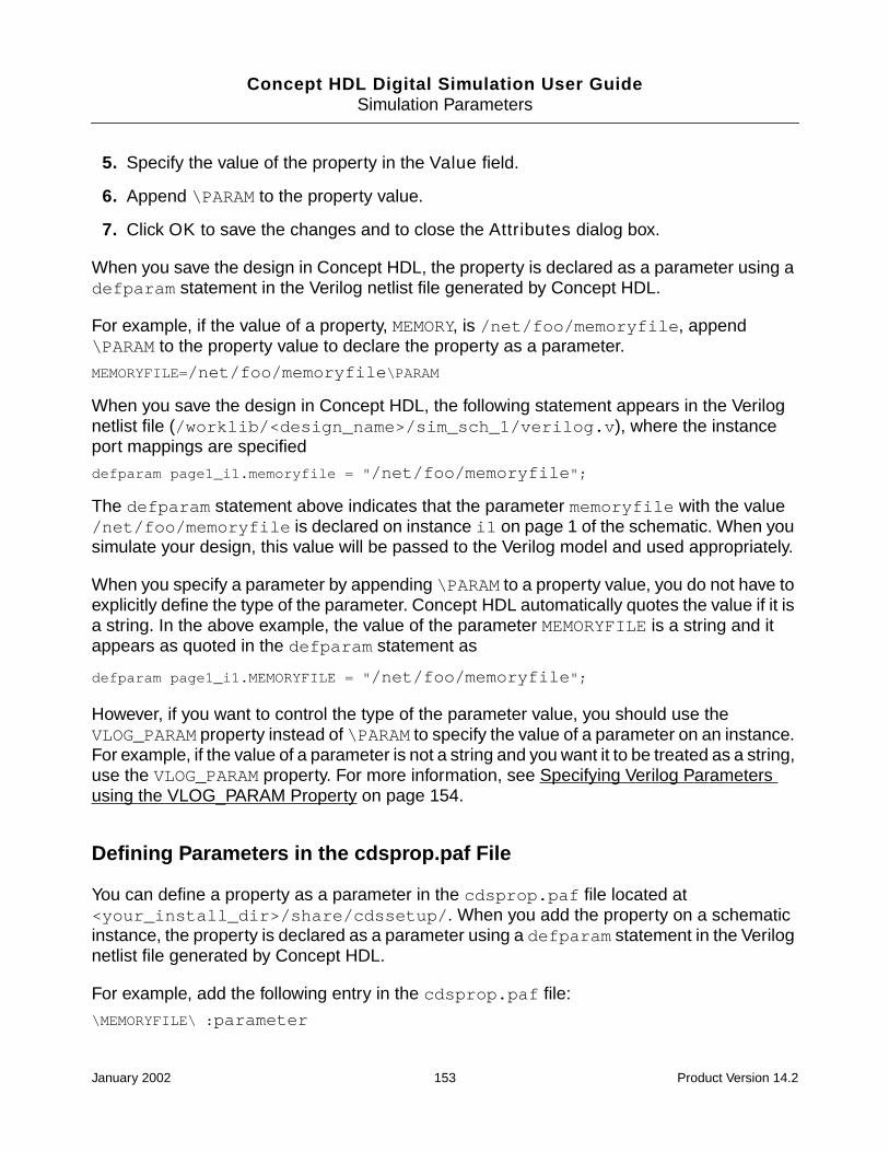
Concept HDL Digital Simulation User GuideSimulation Parameters
5. Specify the value of the property in the Value field.
6. Append \PARAM to the property value.
7. Click OK to save the changes and to close the Attributes dialog box.
When you save the design in Concept HDL, the property is declared as a parameter using adefparam statement in the Verilog netlist file generated by Concept HDL.
For example, if the value of a property, MEMORY, is /net/foo/memoryfile, append\PARAM to the property value to declare the property as a parameter.
MEMORYFILE=/net/foo/memoryfile\PARAM
When you save the design in Concept HDL, the following statement appears in the Verilognetlist file (/worklib/<design_name>/sim_sch_1/verilog.v), where the instanceport mappings are specified
defparam page1_i1.memoryfile = "/net/foo/memoryfile";
The defparam statement above indicates that the parameter memoryfile with the value/net/foo/memoryfile is declared on instance i1 on page 1 of the schematic. When yousimulate your design, this value will be passed to the Verilog model and used appropriately.
When you specify a parameter by appending \PARAM to a property value, you do not have toexplicitly define the type of the parameter. Concept HDL automatically quotes the value if it isa string. In the above example, the value of the parameter MEMORYFILE is a string and itappears as quoted in the defparam statement as
defparam page1_i1.MEMORYFILE = "/net/foo/memoryfile";
However, if you want to control the type of the parameter value, you should use theVLOG_PARAM property instead of \PARAM to specify the value of a parameter on an instance.For example, if the value of a parameter is not a string and you want it to be treated as a string,use the VLOG_PARAM property. For more information, see Specifying Verilog Parametersusing the VLOG_PARAM Property on page 154.
Defining Parameters in the cdsprop.paf File
You can define a property as a parameter in the cdsprop.paf file located at<your_install_dir>/share/cdssetup/. When you add the property on a schematicinstance, the property is declared as a parameter using a defparam statement in the Verilognetlist file generated by Concept HDL.
For example, add the following entry in the cdsprop.paf file:
\MEMORYFILE\ :parameter
January 2002 153 Product Version 14.2

Concept HDL Digital Simulation User GuideSimulation Parameters
The parameter attribute specifies that the property should be treated as a parameter. If youadd the MEMORYFILE property to a schematic instance, it is automatically treated as aparameter and appears as a defparam statement in the Verilog netlist.
If you want to define parameters applicable to a specific project, you can create acdsprop.paf file in the project directory.
Note: If you are using a parameter defined in the cdsprop.paf file on a schematic instance,you need not append \PARAM to the value of the parameter.
Specifying Verilog Parameters using the VLOG_PARAM Property
You can also specify Verilog parameters on schematic instances using the VLOG_PARAMproperty. The VLOG_PARAM property allows you to control the type of the parameter value.For example, if the value of a parameter is not a string and you want it to be treated as a string,use the VLOG_PARAM property.
Syntax
VLOG_PARAMxx=Name:Type
Name=Value
where xx is an integer.
To specify a Verilog parameter on a schematic instance using the VLOG_PARAM property, dothe following:
1. In Concept HDL, choose Text > Attributes.
2. Click on the instance to display the Attributes dialog box.
3. Click Add.
4. Type VLOG_PARAMxx (where xx is an integer) in the Name field.
5. In the Value field, specify the name and type of the parameter value in the formatName:Type.
6. Click Add.
7. Type the name of the parameter (as specified in step 5) in the Name field.
8. Specify the value of the parameter in the Value field.
9. Click OK to save the changes and to close the Attributes dialog box.
January 2002 154 Product Version 14.2

Concept HDL Digital Simulation User GuideSimulation Parameters
When you save the design in Concept HDL, the property is declared as a parameter using adefparam statement in the Verilog netlist file generated by Concept HDL.
For example, add the following properties to an instance i1 on page 1 of your design:
VLOG_PARAM01=ABCD:string
ABCD=4
When you save the design in Concept HDL, the following statement appears in the Verilognetlist file (/worklib/<design_name>/sim_sch_1/verilog.v), where the instanceport mappings are specified
defparam page1_i1.ABCD = "4";
Note that in the defparam statement above, the value 4 of the parameter ABCD is treated asa string.
Specifying the Type of Verilog Parameter for Multiple Schematic Instances
If you want to add a parameter on multiple schematic instances, and explicitly specify the typeof that parameter, instead of adding the VLOG_PARAM property on each instance, you cando the following:
1. Place the DRAWING symbol from the standard library on the schematic.
2. Add the VLOG_PARAM property on the DRAWING symbol.
Note: You should specify only the name and type of the parameter on the DRAWINGsymbol. You should not add the parameter and specify its value on the DRAWING symbol.For more information on the VLOG_PARAM property, see Specifying Verilog Parametersusing the VLOG_PARAM Property on page 154.
3. Add the parameter to instances on the schematic and specify the value of the parameteras <value>\param.
For example, if you want to declare the parameter ABCD with the value of the type string onmultiple schematic instances, do the following:
1. Place a DRAWING symbol from the standard library on the schematic and add thefollowing property on the DRAWING symbol:
VLOG_PARAM01=ABCD:string
Note: You should specify only the name and type of the parameter on the DRAWINGsymbol. You should not add the property ABCD and specify its value on the DRAWINGsymbol.
2. Add the parameter to instances on the schematic.
January 2002 155 Product Version 14.2

Concept HDL Digital Simulation User GuideSimulation Parameters
For example, add the parameter ABCD on instance i1 of the schematic as below:
ABCD=2\param
Similarly, add the parameter ABCD to instance i2 as below:
ABCD=3\param
When you save the design in Concept HDL, the defparam statement in the Verilog netlist(given below) for instance i1 and i2 will have their values quoted because the type specifiedfor the ABCD parameter is string.
deparam page1_i1.ABCD = "2";
deparam page1_i2.ABCD = "3";
Passing the Value of a Verilog Parameter from a Top Level Design to aLower Level Design
You can pass the value of a Verilog parameter declared on a top level design to a lower leveldesign. For example, suppose you have an upper level block, TOP, which instantiates a lowerlevel design MID. You can pass the value of a Verilog parameter declared on block TOP todesign MID.
To pass the value of a parameter from a top level block, TOP, to a lower level design, MID, dothe following:
1. Place the VERILOG_DECS symbol from the standard library on the top level design.
2. Add the VLOG_PARAM property on the VERILOG_DECS symbol to declare a parameter,say MEMORY. For more information on the VLOG_PARAM property, see Specifying VerilogParameters using the VLOG_PARAM Property on page 154.
3. Add the MEMORY parameter to the block TOP on the top level design. For example,specify the value of the parameter as /net/foo/memoryfile\param.
4. Place the VERILOG_DECS symbol from the standard library on the lower level design.
5. Add the VLOG_PARAM property on the VERILOG_DECS symbol to declare a parameterwith the same name as in the top level design. In this case, declare the parameterMEMORY. For more information on the VLOG_PARAM property, see Specifying VerilogParameters using the VLOG_PARAM Property on page 154.
6. Place the DRAWING symbol from the standard library on the lower level design.
7. Add the VLOG_PARAM property on the DRAWING symbol.
Note: You should specify only the name and type of the parameter on the DRAWINGsymbol. You should not add the parameter and specify its value on the DRAWING symbol.For more information on the VLOG_PARAM property, see Specifying Verilog Parameters
January 2002 156 Product Version 14.2

Concept HDL Digital Simulation User GuideSimulation Parameters
using the VLOG_PARAM Property on page 154.
8. Add the parameter MEMORY=$MEMORY on instance I8 on the lower level design.
The value of the parameter MEMORY placed on the block TOP on the top level design willbe passed to the instance I8 on the lower level design. The passing of parameter valuesis represented in the Verilog netlist given below:
deparam page1_i8.MEMORY = MEMORY;
Precedence for Determining the Type of a Parameter
Concept HDL determines the type of a parameter from the VLOG_PARAM property on aninstance by using the following rules:
■ If there is a mismatch in the parameter type across instances of the same component,Concept HDL displays the following error message and the type specified on the firstinstance is used.
240 ERROR "parameter/generic type should be consistent across the instances."
■ If the type of the parameter is also specified on a VERILOG_DECS symbol, Concept HDLchecks for consistency between the type specified on the instance and theVERILOG_DECS symbol. If there is a mismatch, the following error message is displayedand the type specified on the instance is used.
242 ERROR " parameter type specified on instance differs with parameter typespecified on drawing body."
If the type of a parameter is not specified on any instance, the type specified on theVERILOG_DECS symbol is used. If the parameter type is not specified on any instanceor the VERILOG_DECS symbol, then Concept HDL determines the type by applying itsinternal algorithm.
Specifying Verilog Parameters on Symbols
Parameters can be added on symbols with or without default values. You can modify thesevalues when the symbol is instantiated in the schematic.
Syntax
Name = value\param
-Or-
Name = ?\param
-Or-
January 2002 157 Product Version 14.2

Concept HDL Digital Simulation User GuideSimulation Parameters
VLOG_PARAMxx = Name:Type
Name = Value
-Or-
VLOG_PARAMxx = Name:Type
Name = ?
Case Sensitivity of Parameters
The case of values of parameters is always preserved, and the parameter names arelowercased in the Verilog netlist created by Concept HDL. For example, the parameter
VHDL_PARAM01=MEMORYFILE:string
MEMORYFILE=/net/foo/memoryfile
is written in the Verilog netlist as
defparam page1_i1.memoryfile = "/net/foo/memoryfile";
To define the name of the parameter MEMORYFILE as case-sensitive (that is, the case shouldbe preserved), add the following entry in the cdsprop.paf file located at<your_install_dir>/share/cdssetup/
\MEMORYFILE\ :preservename
The preservename attribute specifies that the case of the parameter name should alwaysbe preserved.
The parameter will now be written in the Verilog netlist as
defparam page1_i1.MEMORYFILE = "/net/foo/memoryfile";
Specifying Generics for VHDL Simulation
Parameters are called generics in VHDL. Generics always have a type associated with them.You can specify VHDL generics by using the VHDL_GENERIC property.
The VHDL_GENERIC property can be added on the symbol with or without a default value.When you save the symbol, the generic is declared in the entity view of the part. It is essentialfor the generic to be declared in the entity for VHDL.
Note: You should not add the VHDL_GENERIC property on a schematic instance.
Syntax
VHDL_GENERICxx=Name:Type
January 2002 158 Product Version 14.2

Concept HDL Digital Simulation User GuideSimulation Parameters
Name=?
-Or-
VHDL_GENERIC=Name:Type
Name=Value
If the value specified is other than ?, it is defined as the default value for the parameter in theentity view. Otherwise, no default value is specified in the entity. You can modify the value ofthe parameter for different instances of a component when you instantiate the symbol in theschematic.
For VHDL, the type of the generic is always determined by the type specified for that genericin the entity view for the part. If a component has a generic declared in its entity view as astring, whenever you place the component in a schematic and specify the value for thegeneric, the value will be quoted in the VHDL netlist (unless $ is used in the beginning of thegeneric value). For more information, see Passing the Value of One Parameter or Generic toAnother on page 161.
To add the VHDL_GENERIC property on a symbol, do the following:
1. In Concept HDL, choose Text > Attributes.
2. Click on the origin of the symbol to display the Attributes dialog box.
3. Click Add.
4. Type VHDL_GENERICxx (where xx is an integer) in the Name field.
5. In the Value field, specify the name and type of the generic value in the formatName:Type.
6. Click Add.
7. Type the name of the generic (as specified in step 5) in the Name field.
8. Specify the value of the generic in the Value field.
You can specify a value or ?.
9. Click OK to save the changes and to close the Attributes dialog box.
10. Choose File > Save to save the symbol.
You can instantiate the symbol in your schematic and modify the value of the VHDL_GENERICproperty on the schematic instance.
January 2002 159 Product Version 14.2

Concept HDL Digital Simulation User GuideSimulation Parameters
Passing Values of Generics from an Upper Level Design to a Lower LevelDesign
You can pass the value of a VHDL generic declared on a top level design to a lower leveldesign as below:
1. Place the VHDL_DECS symbol from the standard library on the lower level design.
2. Add the VHDL_GENERIC property on the VHDL_DECS symbol to declare a parameter,say MEMORY. This declares the generic in the entity view for that design. For moreinformation on the VHDL_GENERIC property, see Specifying Generics for VHDLSimulation on page 158.
3. Choose Tools > Generate View and create a symbol view for the design.
The generic is added on the symbol.
4. Instantiate the symbol in the upper level design and modify the value of the generic asrequired.
Case Sensitivity of Generics
The case of the values of generics is always preserved and the generic names arelowercased in the VHDL netlist file (vhdl.vhd) created by Concept HDL. For example, thegeneric
VHDL_GENERIC01=MEMORYFILE:string
MEMORYFILE=/net/foo/memoryfile
is written in the VHDL netlist as
defparam page1_i1.memoryfile = "/net/foo/memoryfile";
To define the name of the generic MEMORYFILE as case-sensitive (that is, the case shouldbe preserved), add the following entry in the cdsprop.paf file located at<your_install_dir>/share/cdssetup/
\MEMORYFILE\ :preservename
The preservename attribute specifies that the case of the generic name should always bepreserved.
The generic will now be written in the VHDL netlist as:
defparam page1_i1.MEMORYFILE = "/net/foo/memoryfile";
January 2002 160 Product Version 14.2

Concept HDL Digital Simulation User GuideSimulation Parameters
Passing the Value of One Parameter or Generic toAnother
If you want to pass the value of a parameter or generic ABCD, to another parameter or genericXYZ, assign the value for XYZ as $ABCD in the VLOG_PARAM, VHDL_GENERIC, or \paramstatement. In the Verilog and VHDL netlists, the value assigned to the parameter or genericXYZwill be ABC (without the quotes). During simulation, the value of the parameter or genericABCD will be assigned to the parameter or generic XYZ.
For example, suppose a top level design instantiates a lower level design, lower_design,and passes the value of a parameter ABCD through a defparam statement. The Verilognetlist for the top level design is given below:
lower_design page1_i1 ();
defparam page1_i1.abcd = "XYZ";
In the Verilog netlist for lower_design, the parameter ABCD is declared in a parameterstatement with a default value.
parameter abcd = "EFGH";
Suppose that there is an instance on lower_design on which you want that the value of aparameter PQR should be the same as the value of parameter ABCD declared on the top leveldesign. To do this, assign the value $ABCD to the parameter PQR. The following defparamstatement is written in the Verilog netlist for lower_level:
defparam page1_i1.pqr = abcd;
Note: The value of parameter PQR is a string but it is not quoted in the netlist because it is avariable. In this example, the value XYZ of the parameter ABCD will be passed from the toplevel design to the parameter PQR specified on the instance in the lower level design.
January 2002 161 Product Version 14.2
Concept HDL Digital Simulation User Guide
ESimulation Properties
Properties serve important and varied functions. They are used to convey a wide range ofinformation about the design and to control analysis processes. A property is a name/valuepair that can be attached to certain objects in a design to convey almost any information.
A number of predefined properties are used by tools in the PCB design flow to recordinformation needed by the Timing Verifier, the Simulator, and the Packager. Other propertiescan be defined by the user to convey information to design programs, or to be passed throughto other systems (such as simulators, physical design systems, and so on).
This section describes the properties that are supported for simulation. See the PCBSystems Properties Reference for information on all the properties supported by CadencePCB design software.
The predefined properties that are supported for simulation are listed below. Click on aproperty name for more information on the property.
January 2002 162 Product Version 14.2

Concept HDL Digital Simulation User GuideSimulation Properties
You can also specify user defined properties in the Verilog and VHDL map files. For more
Property Attached to or used in
NO_REP_PRIM attached to component
attached to symbol
MODEL_DIR attached to component instance
attached to symbol
MODEL_FILE attached to component instance
attached to symbol
PORT_ORDER used in map file
attached to component
REMOVE attached to component
attached to symbol
SIM_BIND_VIEW attached to component
attached to symbol
SIM_MAP_VIEW attached to component
attached to symbol
SIZE attached to component
attached to symbol
SPLIT_INST attached to component
attached to symbol
SPLIT_INST_NAME attached to component
attached to symbol
VERILOG_LIB attached to component
attached to symbol
VERILOG_MODEL attached to component
attached to symbol
used in Verilog map file
VERILOG_NAME used in Verilog map file
January 2002 163 Product Version 14.2

Concept HDL Digital Simulation User GuideSimulation Properties
information, see Specifying User-Defined Properties in Verilog Map Files on page 182, andSpecifying User-Defined Properties in VHDL Map Files on page 184.
NO_REP_PRIM
Use the NO_REP_PRIM=TRUE property on an instance:
■ if you do not want the instance to be replicated in the netlist or
■ if you do not want to pass the SIZE parameter with the correct value to the behavioralmodel.
Note: When the property NO_REP_PRIM=TRUE is not found on an instance, theConcept HDL netlister automatically replicates the instance in the netlist with the actual valueof the SIZE property specified on the instance.
In the figure given below, an instance of component ls00 has the property SIZE=4.
The instance will be replicated four times in the netlist as below:
SN74LS00 page1_i1__1 (._1A(/* unconnected */),
._1B(/* unconnected */),
._1Y(/* unconnected */),
._2A(/* unconnected */),
._2B(/* unconnected */),
._2Y(/* unconnected */),
._3A(/* unconnected */),
VHDL_MODEL attached to component
attached to symbol
used in VHDL map file
VHDL_NAME used in VHDL map file
Property Attached to or used in
January 2002 164 Product Version 14.2

Concept HDL Digital Simulation User GuideSimulation Properties
._3B(/* unconnected */),
._3Y(/* unconnected */),
._4A(a[0]),
._4B(b[0]),
._4Y(c[0]));
SN74LS00 page1_i1__2 (._1A(/* unconnected */),
._1B(/* unconnected */),
._1Y(/* unconnected */),
._2A(/* unconnected */),
._2B(/* unconnected */),
._2Y(/* unconnected */),
._3A(/* unconnected */),
._3B(/* unconnected */),
._3Y(/* unconnected */),
._4A(a[1]),
._4B(b[1]),
._4Y(c[1]));
SN74LS00 page1_i1__3 (._1A(/* unconnected */),
._1B(/* unconnected */),
._1Y(/* unconnected */),
._2A(/* unconnected */),
._2B(/* unconnected */),
._2Y(/* unconnected */),
._3A(/* unconnected */),
._3B(/* unconnected */),
._3Y(/* unconnected */),
._4A(a[2]),
._4B(b[2]),
._4Y(c[2]));
SN74LS00 page1_i1__4 (._1A(/* unconnected */),
._1B(/* unconnected */),
._1Y(/* unconnected */),
._2A(/* unconnected */),
._2B(/* unconnected */),
._2Y(/* unconnected */),
._3A(/* unconnected */),
._3B(/* unconnected */),
._3Y(/* unconnected */),
January 2002 165 Product Version 14.2

Concept HDL Digital Simulation User GuideSimulation Properties
._4A(a[3]),
._4B(b[3]),
._4Y(c[3]));
Now, if you add the NO_REP_PRIM=TRUE property on the instance, the instance will not bereplicated in the netlist (see netlist sample below).
SN74LS00 page1_i1 (._1A(a[0]),
._1B(b[0]),
._1Y(c[0]),
._2A(a[1]),
._2B(b[1]),
._2Y(c[1]),
._3A(a[2]),
._3B(b[2]),
._3Y(c[2]),
._4A(a[3]),
._4B(b[3]),
._4Y(c[3]));
Note: The NO_REP_PRIM property is effective only when its value is TRUE. For all othervalues, the property is ignored.
MODEL_DIR
The MODEL_DIR property is used when you want to bind different instances of a componentto different model libraries. This property is used to specify the directory that contains themodel to be used for binding the component. The syntax used is
MODEL_DIR = <path_to_the_model_library>
While specifying the location of the model library, ensure that only backslash (/) is used as aseparator. Within the directory specified, you must have a file <model_name>.v thatcontains the model definition.
For example, consider that LS00 is instantiated in a design and the model used for simulatingthe LS00 component is ls00. If you add the MODEL_DIR property set to models_ver forinstance-specific binding, then the models_ver directory must have a file ls00.v,otherwise the Concept HDL netlister will generate a warning and ignore the MODEL_DIRproperty.
Values assigned to the MODEL_DIR property are case-sensitive.
January 2002 166 Product Version 14.2

Concept HDL Digital Simulation User GuideSimulation Properties
Caution
Before using the MODEL_DIR property for specifying the model library,ensure that the component binding is correct. In case you do not want touse the default configuration, use the SIM_BIND_VIEW orSIM_MAP_VIEW property to specify the correct view for binding thecomponents.
A part of the netlist that is generated after the MODEL_DIR property is attached to LS00 isshown below. The simulation model is ls00, and the value assigned to the MODEL_DIRproperty is wrapper_ver. The additions in the netlist because of the MODEL_DIR propertyare in bold typeface.
‘uselib dir = wrappers_ver libext=.v
ls00 page1_i2 (.a(b),
.b(unnamed_1_ls00_i2_b),
.\y* (unnamed_1_ls00_i2_y));
defparam page1_i2.size = 1;
‘uselib
Notice that when the MODEL_DIR property is attached to a component, a ‘uselib statementgets added in the simulation netlist. The ‘uselib compiler directive specifies the locationwhere Verilog-XL should look for the definitions of modules and user-defined primitives(UDPs) used in the schematic design. The model file extension should be .v. This isindicated by libext=.v in the ‘uselib statement.
MODEL_FILE
The MODEL_FILE property is very similar to the MODEL_DIR property, except that theMODEL_FILE property is used to specify the location of a verilog file containing the modeldefinition for simulating the component. To specify the MODEL_FILE property on an instance,add the following:
MODEL_FILE = <path>/verilog.v
where path is the location of the verilog.v file containing the model definition. Whilespecifying the path, ensure that only backslash(/) is used. Notice that the file specified by theMODEL_FILE property is always a verilog file.
January 2002 167 Product Version 14.2

Concept HDL Digital Simulation User GuideSimulation Properties
Caution
Before using the MODEL_FILE property for specifying the model library,ensure that the component binding is correct. In case you do not want touse the default configuration, use the SIM_BIND_VIEW or theSIM_MAP_VIEW properties to specify the correct view for binding thecomponents.
A part of the netlist that is generated after the MODEL_FILE property is attached to LS00 isshown below. The additions in the netlist because of the MODEL_FILE property are in boldtypeface.
// begin instances
‘uselib file = ./models_ver/ls00/vlog_behavioral/verilog.v
ls00 page1_i1 (._1A(/* unconnected */),
._1B(/* unconnected */),
._1Y(/* unconnected */),
._2A(/* unconnected */),
._2B(/* unconnected */),
._2Y(/* unconnected */),
._3A(/* unconnected */),
._3B(/* unconnected */),
._3Y(/* unconnected */),
._4A(a),
._4B(sel),
._4Y(unnamed_1_ls00_i1_y));
‘uselib
Note: You can specify either the MODEL_FILE property or the MODEL_DIR property onan instance. In case both the properties are specified on a single instance, theMODEL_DIR property is ignored.
Important
The MODEL_DIR and MODEL_FILE properties, which are used for providinginstance-specific model binding, are understood only by the Verilog-XL simulator.For instance-specific binding using NC Verilog simulator, use the VERILOG_LIBproperty.
January 2002 168 Product Version 14.2

Concept HDL Digital Simulation User GuideSimulation Properties
PORT_ORDER
Use the PORT_ORDER property on an instance or in a map file if you want to use the portnames of the model instead of the pin names on the instance.
Note: The PORT_ORDER property specified on an instance overrides the PORT_ORDERproperty specified in the map file for the instance.
Syntax
PORT_ORDER = ‘(port1, port2 ...)’;
Note: If the port is a vector, a full description for the port (such as A[3:0]) is required. Thevector information is useful for Concept HDL to reconstruct the bus connected to the port.
The order in which the port names of an instance are printed in the netlist is explained belowwith the help of a sample map file:
FILE_TYPE=VHDL_MAP;
PRIMITIVE ’IDT7164’;
DEFAULT_MODEL=IDT7164L_20;
UPPER_CASE=TRUE;
MODEL ’IDT7164L_20’, ’IDT7164L_25’, ’IDT7164L_30’, ’IDT7164L_35’,’IDT7164L_45’, ’IDT7164L_55M’, ’IDT7164L_70M’, ’IDT7164L_85M’;
PROPERTY
MEMORYFILE;
PORT_ORDER = ’(A0, A1, A2, A3, A4, A5, A6, A7, A8, A9, A10, A11, A12, CS1_,CS2, OE_, WE_, IO8, IO7, IO6, IO5, IO4, IO3, IO2, IO1)’
END_PROPERTY;
PIN_MAP
’A’<12>=’(A12, A12, A12, A12, A12, A12, A12, A12)’;
’A’<11>=’(A11, A11, A11, A11, A11, A11, A11, A11)’;
’A’<10>=’(A10, A10, A10, A10, A10, A10, A10, A10)’;
’A’<9>=’(A9, A9, A9, A9, A9, A9, A9, A9)’;
’A’<8>=’(A8, A8, A8, A8, A8, A8, A8, A8)’;
’A’<7>=’(A7, A7, A7, A7, A7, A7, A7, A7)’;
’A’<6>=’(A6, A6, A6, A6, A6, A6, A6, A6)’;
’A’<5>=’(A5, A5, A5, A5, A5, A5, A5, A5)’;
’A’<4>=’(A4, A4, A4, A4, A4, A4, A4, A4)’;
’A’<3>=’(A3, A3, A3, A3, A3, A3, A3, A3)’;
’A’<2>=’(A2, A2, A2, A2, A2, A2, A2, A2)’;
’A’<1>=’(A1, A1, A1, A1, A1, A1, A1, A1)’;
’A’<0>=’(A0, A0, A0, A0, A0, A0, A0, A0)’;
’-CS1’=’(CS1_*8)’;
January 2002 169 Product Version 14.2

Concept HDL Digital Simulation User GuideSimulation Properties
’CS2’=’(CS2*8)’;
’IO’<0>=’(IO8, IO7, IO6, IO5, IO4, IO3, IO2, IO1)’;
’-OE’=’(OE_*8)’;
’-WE’=’(WE_*8)’;
’DUMMY’=’(_DUMMY)’;
END_PIN;
END_MODEL;
END_PRIMITIVE;
END.
■ If the PORT_ORDER property is specified on an instance or in a map file and thePosition Mapping check box in the Netlist tab of the Concept HDL Digital SimulationInterface is selected, the port order specified in the PORT_ORDER property is used forprinting the port names in that order.
Taking the example of the map file given above, if the Position Mapping check box isselected, the ports will be printed in the following order:
’(A0, A1, A2, A3, A4, A5, A6, A7, A8, A9, A10, A11, A12, CS1_, CS2, OE_, WE_,IO8, IO7, IO6, IO5, IO4, IO3, IO2, IO1)’
■ If the PORT_ORDER property is specified on an instance or in a map file and thePosition Mapping check box in the Netlist tab of the Concept HDL Digital SimulationInterface is not selected, the ports specified in the PORT_ORDER property are printedin the alphabetical order.
Note: The ports that are not specified in the PORT_ORDER property are ignored andnot printed in the netlist.
Taking the example of the map file given above, if the Position Mapping check box isnot selected, the ports will be printed in the alphabetical order. The port _DUMMYcorresponding to the pin DUMMY is ignored and not printed in the netlist.
’(A0, A1, A10, A11, A12, A2, A3, A4, A5, A6, A7, A8, A9, CS1_, CS2, IO8, IO7,IO6, IO5, IO4, IO3, IO2, IO1, OE_, WE_)’
■ If the PORT_ORDER property is not specified on an instance or in a map file, themapped ports specified in the PIN_MAP section of the map file are printed in thealphabetical order, as below:
’(A0, A1, A10, A11, A12, A2, A3, A4, A5, A6, A7, A8, A9, CS1_, CS2, _DUMMY,IO8, IO7, IO6, IO5, IO4, IO3, IO2, IO1, OE_, WE_)’
REMOVE
This body property is used either on bodies in the library or on instances of bodies in theschematic design.
January 2002 170 Product Version 14.2
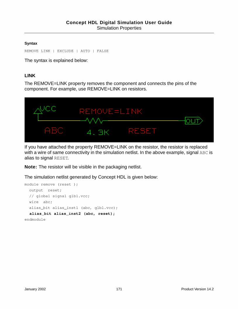
Concept HDL Digital Simulation User GuideSimulation Properties
Syntax
REMOVE LINK | EXCLUDE | AUTO | FALSE
The syntax is explained below:
LINK
The REMOVE=LINK property removes the component and connects the pins of thecomponent. For example, use REMOVE=LINK on resistors.
If you have attached the property REMOVE=LINK on the resistor, the resistor is replacedwith a wire of same connectivity in the simulation netlist. In the above example, signal ABC isalias to signal RESET.
Note: The resistor will be visible in the packaging netlist.
The simulation netlist generated by Concept HDL is given below:
module remove (reset );
output reset;
// global signal glbl.vcc;
wire abc;
alias_bit alias_inst1 (abc, glbl.vcc);
alias_bit alias_inst2 (abc, reset);
endmodule
January 2002 171 Product Version 14.2

Concept HDL Digital Simulation User GuideSimulation Properties
EXCLUDE
The REMOVE=EXCLUDE property removes the component and all nodes on thecomponent. For example, use REMOVE=EXCLUDE on capacitors and non-seriesterminating resistors.
Once you have attached the property REMOVE=EXCLUDE on the resistor, the resistor isreplaced by an open in the simulation netlist.
Note: The resistor is visible in the packaging netlist.
The netlist generated by Concept HDL is given below:
module remove (reset );
output reset;
// global signal glbl.vcc;
wire abc;
alias_bit alias_inst1 (abc, glbl.vcc);
endmodule
AUTO
The REMOVE=AUTO property removes the component and connects the pins of thecomponent if the component is connected between two internal nodes. If one pin of thecomponent is connected to a power supply, for example VCC, Concept HDL replaces thecomponent with a pullup in the simulation netlist. If one pin of the component is connected to
January 2002 172 Product Version 14.2

Concept HDL Digital Simulation User GuideSimulation Properties
a ground, for example GND, Concept HDL replaces the component with a pulldown in theVerilog netlist. For example, use REMOVE=AUTO on resistors.
In this example, the property REMOVE=AUTO is attached to resistors R1 and R2. ResistorR1 is connected to the power symbol VCC, resulting in a pullup in the netlist. Resistor R2 isconnected to the ground symbol GND, resulting in a pulldown in the netlist.
The netlist generated by Concept HDL is shown below:
pulldown (abc);
pullup (reset);
To use the REMOVE=AUTO property on a component
1. Specify the name of the ground symbol (for example, GND and GNDD) in the Supply 0field in the Verilog Netlist dialog box.
To access the Verilog Netlist dialog box, do the following:
a. In Concept HDL, choose Tools > Options.
The Concept Options dialog box appears.
b. Select the Output tab.
Ensure that the Create Netlist check box is selected.
c. Click the Options button against the Verilog check box.
The Verilog Netlist dialog box appears.
2. Specify the name of the power symbol (for example, VCC and VDC) in the Supply 1 fieldin the Verilog Netlist dialog box.
January 2002 173 Product Version 14.2

Concept HDL Digital Simulation User GuideSimulation Properties
3. Attach the REMOVE=AUTO property to the component.
4. Connect a wire to this component.
5. Add a power symbol, such as VCC or GND, that is added to the SUPPLY1 or SUPPLY0list, to one of the terminals of the component. This results in a pullup or pulldown net.
Note: If you use the REMOVE=AUTO property on a component that has only one pin in eachsection and
❑ If one of the terminals is connected to a power symbol that is declared as SUPPLY1or SUPPLY0, then Concept HDL changes it to a pullup or pulldown.
❑ If a power symbol is not declared as SUPPLY1 or SUPPLY0, Concept HDL treatsthe REMOVE=AUTO property as the REMOVE=LINK property.
FALSE
If the REMOVE property is defined on the symbol of a component, the property will beavailable on every instance of the component you place in your design. If you do not want touse the REMOVE property on a specific instance of the component in your design, specifythe REMOVE=FALSE property on that instance. Concept HDL will ignore the REMOVEproperty on an instance if the value of the property is FALSE.
SIM_BIND_VIEW
The SIM_BIND_VIEW property is used to specify the binding for the Verilog models thatappear in the mapped netlist. If you are using wrappers for simulation, specify a wrapper viewname as the value for this property. If you are using map files for simulation, the propertyvalue should be a binding for the mapped Verilog model.
Example
If you are using a lsoo part in the schematic and specify
SIM_BIND_VIEW=vlog_model
the lsoo part is bound to the vlog_model view of lsoo. However, if you have specified
VERILOG_MODEL=TTLOO
and
SIM_BIND_VIEW=vlog_model
the lsoo part is bound to the vlog_model view of TTL00.
January 2002 174 Product Version 14.2

Concept HDL Digital Simulation User GuideSimulation Properties
If you are using parts having shared pins (physically different pins, with the same pin nameon different symbols) you must specify the wrapper’s view name also as the property valuefor the SIM_BIND_VIEW property. Concept HDL finds the location of the wrapper from thisview.
The SIM_BIND_VIEW property must be placed on any one of the split parts if there arecommon or shared pins across different split parts. If the same property SIM_BIND_VIEW orthe same parameter is found on more than one instance of the same SPLIT_INST_NAMEgroup, Concept HDL takes the property from the instance having lower path values andignores the property from the other instances in the same split instance group. For moreinformation, see “SPLIT_INST_NAME” on page 176.
SIM_MAP_VIEW
This is an instance property that overrides the default map file viewlist specified in thesimulation configuration. For example, if the default map file viewlist for the cfg_verilogsimulation configuration is swift_map, you can specify SIM_MAP_VIEW=vlog_map tooverride the map view binding.
SIZE
The SIZE property is used to specify the width of pin names and signal names and to definesize expansion. Using the SIZE property can greatly minimize the number of parts andinterconnections.
The SIZE property, when used inside the hierarchy, generates specific versions of a module.Ultimately, the SIZE property is propagated down to the primitive level. Most of the primitivesin Concept HDL use the SIZE property to specify the number of bits of the primitive. The valueof the SIZE property can be fixed or variable (SIZE=SIZE). In this case, the size of theprimitive is taken from the SIZE property attached to the component being modeled.
For simple primitives, the SIZE property is interpreted as multiple instances of the primitive.The bits of a bus connected to a sized pin of a primitive are split between the replicatedinstances of the primitive. For example, if bus A<1..0> is connected to a sized pin of a BUFprimitive with SIZE=2, the bit A<0> is connected to the first instance and the bit A<1> isconnected to the second instance. Simple SIZED primitives are translated by Concept HDLas multiple instances of the primitive.
For more complex primitives, the SIZE property cannot be directly interpreted as a replicationof the primitive. In an example of an ADDER primitive with SIZE greater than two, theCarryOut of one stage needs to be connected to the CarryIn of the next stage. To accurately
January 2002 175 Product Version 14.2

Concept HDL Digital Simulation User GuideSimulation Properties
model the SIZE property on this type of primitive, the primitive must be described as aparameterized behavioral Verilog model.
■ When the property NO_REP_PRIM is found in the library description for a primitive,Concept HDL does not replicate this primitive or pass the SIZE parameter with thecorrect value to the behavioral model.
■ When the property NO_REP_PRIM=TRUE is not found in the library description for aprimitive, Concept HDL assumes it to be a simple gate and automatically replicates thisgate with the actual value of SIZE.
SPLIT_INST
All split parts of a device must have a SPLIT_INST property set to TRUE attached to thesymbol (by the librarian developing the split parts). If this property is not attached to thesymbols, the property cannot be attached to the split parts you use in your schematic.
In the simulation netlist, all parts with the SPLIT_INST property set to TRUE are merged intoa single instance. In cases where the schematic has multiple instances of a split part, thenalong with the SPLIT_INST property set to TRUE, you should also have the $LOCATIONproperty specified on all split parts. A group of split parts of the same device is known as splitinstance group. Parts having same value for the $LOCATION property form one split instancegroup.
For example, suppose there is a large pin count device, ASYM_PART, which is split into fourparts. All the four split parts must have the SPLIT_INST property set to TRUE, attached tothem. Now if a schematic has only one instance of all four ASYM_PART split parts, theConcept HDL netlister will merge all devices into a single instance in the simulation netlist.The instance name in the generated netlist will be ASYM_PART_SPLIT_1. But in case thereare multiple instances of a ASYM_PART split part, Concept HDL netlist will generate awarning and use internal logic to group the parts into different split inst groups.
To remove this warning you must attach the $LOCATION property with the same value on allsplit parts that should form a single split inst group. When you save a schematic inConcept HDL, all split parts with the same value for the $LOCATION property are merged intoa single instance in the netlist.
SPLIT_INST_NAME
Attach the $SPLIT_INST_NAME property on all split parts that have to be merged into asingle instance in the simulation netlist. By default, the value assigned to the$SPLIT_INST_NAME property is ?. If the default value is used, in the simulation netlist allsplit parts are merged into a single instance named <device_name>_split_1.
January 2002 176 Product Version 14.2

Concept HDL Digital Simulation User GuideSimulation Properties
For example, consider a device, ASYM_PART, which is split into four parts. All four parts havethe $SPLIT_INST_NAME property set to ?. Concept HDL netlister reads the property andmerges the four split parts to generate one instance of the part with the instance name asasym_part_split_1.
If you need multiple instances of a split part, you should specify the property$SPLIT_INST_NAME with different values for each instance. The property value becomesthe becomes the instance name in the simulation netlist and therefore, must be the same forall split parts in a split inst group.
For example,
■ Attach the SPLIT_INST_NAME property set to INST_FIRST to all the body drawings ofthe split part for the first instance.
■ Attach the SPLIT_INST_NAME property set to INST_SECOND for the second instance.
The output in the netlist will be
SPLIT_PART INST_FIRST(.....);
SPLIT_PART INST_SECOND(.....);
Caution
Do not use the instance name in the following format:i<integer>This can cause a naming conflict because Concept HDL generatesinstance names such as I1P, I2P, and so on.
VERILOG_LIB
To support instance-specific binding in the NC Verilog simulation flow, you need to attach theVERILOG_LIB property on the component instance. For example, if ls00 is instantiated on adrawing, you have to add the following for instance-specific library binding support:
VERILOG_LIB=lsttl_models
where VERILOG_LIB is the property name and lsttl_models is the associated Veriloglogical library name.
The property will be transferred in the netlist as
ls00 ( *VLOG_LIB="lsttl_models") inst1...
NC Verilog will parse the netlist file (verilog.v), and wherever it finds such an attribute, it willsearch the logical library to find the model for the ls00 part.
January 2002 177 Product Version 14.2

Concept HDL Digital Simulation User GuideSimulation Properties
VERILOG_MODEL
The VERILOG_MODEL property is used to change the name of the Verilog modulegenerated or to select a specific MODEL entry in a Verilog map file. Place this property in thelibrary description for a primitive, in a physical part table, or directly on an instance.
Syntax
VERILOG_MODEL=name
Example
VERILOG_MODEL=SN74LS00
By default, the name of the Verilog module generated is the same name as the originalDRAWING name unless the part has a PART_NAME property defined. Use theVERILOG_MODEL property to specify the exact name of the Verilog module. AVERILOG_MODEL property placed on an instance overrides the same property placed in thelibrary.
How are parts instantiated in the Verilog netlist?
Parts are instantiated in the Verilog netlist using the following rules:
■ If the VERILOG_MODEL property is not present on an instance in the schematic, thepart will be instantiated in the netlist using the model specified as the value of theDEFAULT_MODEL property in the verilog.map file.
For example, if the DEFAULT_MODEL=SN74LS00 property is specified in theverilog.map file, the part will be instantiated in the netlist as below:
SN74LS00 page1_i1 (net1, net2, net3, ...)
■ If the VERILOG_MODEL property is present on an instance in the schematic and if thereis no matching model specified in the MODEL section of the verilog.map file, the partwill be instantiated in the netlist using the model specified as the value of theVERILOG_MODEL property on the schematic instance.
For example, if the VERILOG_MODEL=SN74LS00 property is specified on a part in theschematic and if the MODEL section of the verilog.map file reads as below:
MODEL ’SN74LS153’, ’SIG74LS00’ ;...END_MODEL
the part will be instantiated in the netlist using the VERILOG_MODEL property as below:
SN74LS00 page1_i1 (net1, net2, net3, ...)
January 2002 178 Product Version 14.2

Concept HDL Digital Simulation User GuideSimulation Properties
■ If the VERILOG_MODEL property is present on an instance in the schematic and if thereis a matching model specified in the MODEL section of the verilog.map file, but if theVERILOG_NAME property does not exist for the same MODEL section, the part will beinstantiated in the netlist using the model specified as the value of theVERILOG_MODEL property on the schematic instance.
For example, if the VERILOG_MODEL=SN74LS00 property is specified on a part in theschematic and the MODEL section of the verilog.map file has a matching model, andif the VERILOG_NAME property does not exist for the MODEL section as below:
MODEL ’SN74LS00’, ’SIG74LS00’ ;PROPERTY
...
END_PROPERTY;...END_MODEL
the part will be instantiated in the netlist using the VERILOG_MODEL property, as below:
SN74LS00 page1_i1 (net1, net2, net3, ...)
■ The part will be instantiated in the netlist using the model specified as the value of theVERILOG_NAME property in the verilog.map file if
❑ the VERILOG_MODEL property is present on an instance in the schematic, and
❑ there is a matching model specified in the MODEL section of the verilog.map file,and
❑ the VERILOG_NAME property exists for the MODEL section.
For example, if the VERILOG_MODEL=SN74LS00 property is specified on a part in theschematic and the MODEL section of the verilog.map file has a matching model, andif the VERILOG_NAME property exists for the MODEL section as below:
MODEL ’SN74LS00’, ’SIG74LS00’ ;PROPERTY
VERILOG_NAME = ’SN74LS153’;...
END_PROPERTY;...END_MODEL
the part will be instantiated in the netlist using the VERILOG_NAME property, as below:
SN74LS153 page1_i1 (net1, net2, net3, ...)
For more information on the verilog.map file, see Appendix F, “Map Files.”
January 2002 179 Product Version 14.2

Concept HDL Digital Simulation User GuideSimulation Properties
VERILOG_NAME
The VERILOG_NAME property specifies the actual name of the Verilog model. Internally, allnames for modules are lowercase. If the name of the module you are using is eitheruppercase or contains a mixture of lowercase and uppercase characters, use theVERILOG_NAME property to specify how the module name will appear in the netlist.
Syntax
VERILOG_NAME=’name’
Example
VERILOG_NAME=’TTL00’
VHDL_MODEL
The VHDL_MODEL property is used to change the name of the VHDL module generated orto select a specific MODEL entry in a VHDL map file. Place this property in the librarydescription for a primitive (chips.prt file), in a physical part table, or directly on an instance.
Syntax
VHDL_MODEL=name
Example
VHDL_MODEL=SN74LS241
By default, the name of the VHDL module generated is the same name as the originalDRAWING name unless the part has a PART_NAME property defined. Use theVHDL_MODEL property to specify the exact name of the VHDL module. A VHDL_MODELproperty placed on an instance overrides the same property placed in the library.
How are parts instantiated in the VHDL netlist?
Parts are instantiated in the VHDL netlist using the following rules:
■ If the VHDL_MODEL property is not present on an instance in the schematic, the partwill be instantiated in the netlist using the model specified as the value of theDEFAULT_MODEL property in the vhdl.map file.
For example, if the DEFAULT_MODEL=SN74LS145 property is specified in the vhdl.mapfile, the part will be instantiated in the netlist as below:
January 2002 180 Product Version 14.2

Concept HDL Digital Simulation User GuideSimulation Properties
SN74LS145 page1_i1 (net1, net2, net3, ...)
■ If the VHDL_MODEL property is present on an instance in the schematic and if there isno matching model specified in the MODEL section of the vhdl.map file, theConcept HDL netlister displays a warning message and instantiates the part in the netlistusing the model specified as the value of the VHDL_MODEL property on the schematicinstance.
For example, if the VHDL_MODEL=SN74LS241 property is specified on a part in theschematic and if the MODEL section of the vhdl.map file reads as below:
MODEL ’SN74LS153’, ’SN74LS145’ ;...END_MODEL
the part will be instantiated in the netlist using the VHDL_MODEL property as below:
SN74LS241 page1_i1 (net1, net2, net3, ...)
Important
If there is no matching model specified in the MODEL section of the vhdl.map file,you can add the declaration for that component within a package declaration. Insuch cases, edit the simulation netlist such that in the netlist the package name isvisible before component instantiation. The package declaration is made visible byusing the USE clause. The USE clause syntax is shown below:
USE <package_name>.all
■ If the VHDL_MODEL property is present on an instance in the schematic and if there isa matching model specified in the MODEL section of the vhdl.map file, but if theVHDL_NAME property does not exist for the same MODEL section, the part will beinstantiated in the netlist using the model specified as the value of the VHDL_MODELproperty on the schematic instance.
For example, if the VHDL_MODEL=SN74LS241 property is specified on a part in theschematic and the MODEL section of the vhdl.map file has a matching model, and ifthe VHDL_NAME property does not exist for the MODEL section as below:
MODEL ’SN74LS241’, ’SN74LS145’ ;PROPERTY
...
END_PROPERTY;...END_MODEL
the part will be instantiated in the netlist using the VHDL_MODEL property, as below:
SN74LS241 page1_i1 (net1, net2, net3, ...)
■ The part will be instantiated in the netlist using the model specified as the value of theVHDL_NAME property in the vhdl.map file if:
January 2002 181 Product Version 14.2

Concept HDL Digital Simulation User GuideSimulation Properties
❑ the VHDL_MODEL property is present on an instance in the schematic, and
❑ there is a matching model specified in the MODEL section of the vhdl.map file, and
❑ the VHDL_NAME property exists for the MODEL section.
For example, if the VHDL_MODEL=SN74LS241 property is specified on a part in theschematic and the MODEL section of the vhdl.map file has a matching model, and ifthe VHDL_NAME property exists for the MODEL section as below:
MODEL ’SN74LS241’, ’SN74LS145’ ;PROPERTY
VHDL_NAME = ’SN74LS153’;...
END_PROPERTY;...END_MODEL
the part will be instantiated in the netlist using the VHDL_NAME property, as below:
SN74LS153 page1_i1 (net1, net2, net3, ...)
For more information on the vhdl.map file, see Appendix F, “Map Files.”
VHDL_NAME
The VHDL_NAME property specifies the actual name of the VHDL model. Internally, allnames for modules are in lowercase. If the name of the module you are using is eitheruppercase or contains a mixture of lowercase and uppercase characters, use theVHDL_NAME property to specify how the module name will appear in the netlist.
Syntax
VHDL_NAME=’name’
Example
VHDL_NAME=’SN74LS153’
Specifying User-Defined Properties in Verilog Map Files
Using a Verilog map file, you can specify user-defined properties for Concept HDL to look for.These properties are appear as defparam statements in the Verilog netlist (verilog.v). Formore information on Verilog map files, see Appendix F, “Map Files.”
January 2002 182 Product Version 14.2

Concept HDL Digital Simulation User GuideSimulation Properties
This feature is useful if you are using external Verilog libraries. For example, if a drawing OSCis described as a Verilog behavioral model in an external library, and you want to pass aparameter FREQUENCY to this module, create a Verilog map file that describes theFREQUENCY=10 property as below:
FILE_TYPE = VERILOG_MAP;PRIMITIVE OSC;
DEFAULT_MODEL = OSC;MODEL OSC;
PROPERTYFREQUENCY = 10;
END_PROPERTY;END_MODEL;
END_PRIMITIVE;END.
If you have two instances of component OSC in your schematic,
■ instance i3 on which you have specified the FREQUENCY=20 property
■ instance i4 on which you have not specified the FREQUENCY property
the Verilog netlist (verilog.v) generated by Concept HDL will be as below:
osc page1_i3 ( ... );defparam page1_i3.FREQUENCY = 20;...osc page1_i4 ( ... );defparam page1_i4.FREQUENCY = 10;...
Note that the FREQUENCY=10 property specified in the Verilog map file is passed for instancei4 of the component OSC even though you have not specified the property on the instance.
In the SCALD environment, you could enter user-defined parameters in the Verilogdescription by specifying the parameters in the verilog.v file. This feature is not supportedin the HDL environment.
Note: Concept HDL recognizes and passes properties as uppercase. However, Verilogreference filenames are forced to be in lowercase, regardless of the annotation on theschematic. For example, If there is an instance 15P of AM27S13 with the propertyMEMORYFILE=/USR/RMP/MEM.DAT1, the output netlist will be
AM27513 15P(....);
defparam 15P.MEMORYFILE = “/usr/tmp/mem.dat1”;
For information on case sensitivity of property values, see “Case Sensitivity of PropertyValues” on page 184.
January 2002 183 Product Version 14.2

Concept HDL Digital Simulation User GuideSimulation Properties
Specifying User-Defined Properties in VHDL Map Files
You can specify user-defined properties in the entity file for Concept HDL to look for. For auser-defined property to be output as a generic, you must add the generic to the entity fileand initialize the generic with a default value.
Note: Concept HDL does not read vhdl.map files to get default values for generics.
If the property is attached to a given instance, Concept HDL reads the property value andoverrides the default value using the VHDL generic map construct. For example, if thedrawing OSC is described as a VHDL behavioral model in an external library, and you wantto pass parameter FREQUENCY to this description, modify the entity file to describe theFREQUENCY property.
Concept HDL looks for the property FREQUENCY on any instance of OSC and, if theproperty is found, outputs the value of the property using the generic construct.
For example, the entity file describing frequency might look like the following:
entity xgeneric (
frequency: positive:= 10;port (
y: in std_logic;a: out std_logic);
end x;
If there is an instance U3 of OSC without the FREQUENCY property and another instance4P of OSC with the property FREQUENCY=20, the output netlist contains the following:
U3:OSC generic map(FREQUENCY <= 10)
port map( ... )
U4:OSC generic map(FREQUENCY <= 20)
port map( ....)
Case Sensitivity of Property Values
In the HDL environment, case sensitivity of property names and values is supported in thefront-to-back flow.
Note: In Concept HDL, all property names and values are automatically uppercased. Tochange this behavior, do the following:
1. From the Tools menu in Concept HDL, select Options > Text.
January 2002 184 Product Version 14.2

Concept HDL Digital Simulation User GuideSimulation Properties
2. Uncheck the Upper-case Input check box.
You can now enter property names and property values in any case. They will not beautomatically uppercased by Concept HDL and will be displayed in the schematic in thesame case as they are entered.
You can define properties in the schematic, the occurrence property file, the PPT, and thechips.prt files. These properties can also be fed back from the board.
By default, for all such properties
■ The name of the property is uppercased by tools.
■ The case of the property value is preserved.
You can change the default behavior for specific properties by attaching specific attributes tothem in the cdsprop.paf file, which is located at <your_install_dir>/share/cdssetup. You can edit this file to make necessary changes to the case sensitivity ofproperty names and values. If the attributes have to be applied only to a single project, youcan place the cdsprop.paf file in the project’s directory.
To indicate that the case of a property name should be preserved, use the keywordpreservename. To indicate that the case of a property value should not be preserved, usethe keyword uppercasevalue.
Example:
alt_symbols: uppercasevalue
\TimingVersion\:preservename
In the example, ALT_SYMBOLS is assigned the keyword uppercasevalue. If you now specifythe TimingVersion property, its value will always be uppercased.
The TimingVersion property is specified within backslashes (\) because the cdsprop.paffile is in the VHDL namespace. (In VHDL, backslashes are used to denote that the propertiesare case sensitive.)
The TimingVersion property is assigned the keyword preservename. Therefore, theproperty name will not be uppercased to TIMINGVERSION.
Note: The cdsprop.paf file located at <your_install_dir>/share/cdssetup/contains the default attributes. If you want to define attributes applicable to a specific project,you can create a cdsprop.paf file in the project directory. The attributes specified in thecdsprop.paf file located in the project directory override the attributes specified in thecdsprop.paf file located at <your_install_dir>/share/cdssetup/.
January 2002 185 Product Version 14.2
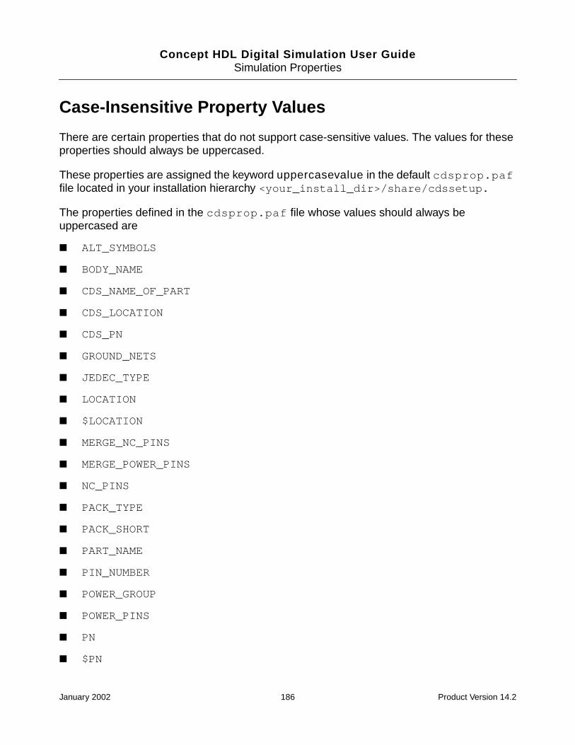
Concept HDL Digital Simulation User GuideSimulation Properties
Case-Insensitive Property Values
There are certain properties that do not support case-sensitive values. The values for theseproperties should always be uppercased.
These properties are assigned the keyword uppercasevalue in the default cdsprop.paffile located in your installation hierarchy <your_install_dir>/share/cdssetup.
The properties defined in the cdsprop.paf file whose values should always beuppercased are
■ ALT_SYMBOLS
■ BODY_NAME
■ CDS_NAME_OF_PART
■ CDS_LOCATION
■ CDS_PN
■ GROUND_NETS
■ JEDEC_TYPE
■ LOCATION
■ $LOCATION
■ MERGE_NC_PINS
■ MERGE_POWER_PINS
■ NC_PINS
■ PACK_TYPE
■ PACK_SHORT
■ PART_NAME
■ PIN_NUMBER
■ POWER_GROUP
■ POWER_PINS
■ PN
■ $PN
January 2002 186 Product Version 14.2

Concept HDL Digital Simulation User GuideSimulation Properties
■ SD_SUFFIX_SEPARATOR
■ SUBDESIGN_SUFFIX
Note: Even if you remove these property assignments from the cdsprop.paf file, theproperty values will continue to be treated as case insensitive.
Important: You can get an updated list of properties from the cdsprop.paf file located inyour installation hierarchy <your_install_dir>/share/cdssetup.
Case-Insensitive Property Names
There are some properties whose names are always treated as case insensitive. Theseproperty names are always uppercased.
The case-insensitive property names are
■ ALT_SYMBOLS
■ BIDIRECTIONAL
■ BODY_NAME
■ BODY_TYPE
■ CDS_LONG_PART_NAME
■ CDS_NAME_OF_PART
■ CDS_PARENT_CHIPS_PHYS_PART
■ CDS_PARENT_PPT
■ CDS_PARENT_PPT_PART
■ CDS_PARENT_PPT_PHYS_PART
■ CDS_PHYS_NET_NAME
■ CDS_PRIM_FILE
■ CDS_SEC
■ CDS_LOCATION
■ CDS_PN
■ GROUP
January 2002 187 Product Version 14.2

Concept HDL Digital Simulation User GuideSimulation Properties
■ HAS_FIXED_SIZE
■ INPUT_LOAD
■ JEDEC_TYPE
■ LOCATION
■ $LOCATION
■ MERGE_NC_PINS
■ MERGE_POWER_PINS
■ NC_PINS
■ NO_BACKANNOTATE
■ OUTPUT_LOAD
■ OUTPUT_TYPE
■ PACK_TYPE
■ PACK_IGNORE
■ PACK_SHORT
■ PART_NAME
■ PATH
■ PINCOUNT
■ PIN_GROUP
■ PIN_NUMBER
■ POWER_GROUP
■ POWER_PINS
■ PN
■ $PN
■ PRIM_FILE
■ ROOM
■ SEC
■ $SEC
January 2002 188 Product Version 14.2
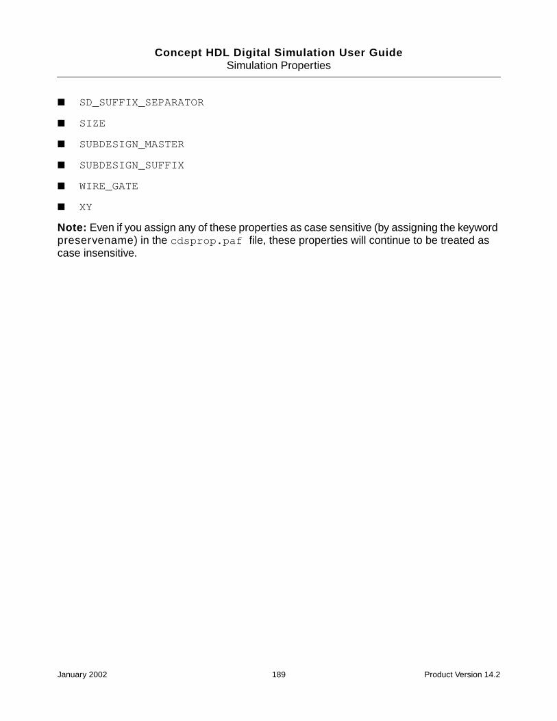
Concept HDL Digital Simulation User GuideSimulation Properties
■ SD_SUFFIX_SEPARATOR
■ SIZE
■ SUBDESIGN_MASTER
■ SUBDESIGN_SUFFIX
■ WIRE_GATE
■ XY
Note: Even if you assign any of these properties as case sensitive (by assigning the keywordpreservename) in the cdsprop.paf file, these properties will continue to be treated ascase insensitive.
January 2002 189 Product Version 14.2

Concept HDL Digital Simulation User Guide
FMap Files
This appendix discusses the following:
■ Verilog Map File on page 190
■ Examples of Verilog Map Files on page 196
■ VHDL Map File on page 199
■ Examples of VHDL Map Files on page 204
Verilog Map File
The Verilog map file (verilog.map) specifies pin-to-port mapping information and theparameters to be passed to the Verilog modules. Usually, this file is only necessary forexternally defined libraries. This file can also be used for user-defined Verilog modules, butthis is not usually necessary.
The Verilog map file must be located in the directory used to stop the expansion of the design(for example, vlog_map) and must be named verilog.map.
The following illustrates the format of a Verilog map file:
FILE_TYPE = VERILOG_MAP;PRIMITIVE ’primitive_name’ [ , ’primitive_name’ ... ];
DEFAULT_MODEL = ’name’;UPPER_CASE = ’TRUE’;MODEL ’verilog_name’ [ , ’verilog_name’ ... ];
PROPERTYPORT_ORDER = ’(port1, port2, ... )’;property_1 = value_1;...property_n = value_n;
END_PROPERTY;PIN_MAP
body_pin_name_1 = verilog_port_name_1;...body_pin_name_n = verilog_port_name_n;
END_PIN;END_MODEL;MODEL ’verilog_name’ [, ’verilog_name’ ... ];
January 2002 190 Product Version 14.2

Concept HDL Digital Simulation User GuideMap Files
...END_MODEL;
END_PRIMITIVE;
PRIMITIVE ’primitive_name’ [ , ’primitive_name’ ... ];...
END_PRIMITIVE;END.
Note: If an entry is longer than one line, use a tilde (~) as a continuation character. The tildecan appear between any two characters in the entry but must be the last character in the line.
PRIMITIVE Section
The PRIMITIVE section describes all the information related to a specific primitive. The nameused for the primitive is either the body name used in Concept HDL or the part name specifiedin the PART_NAME property. For example, in the lsttl library, LS00 has a PART_NAME =74LS00 property and the primitive name 74LS00. You can modify this name by adding aPACK_TYPE property on a specific instance. For example, if an instance of LS00 has aPACK_TYPE = DIP property, the primitive name is 74LS00_DIP.
In the Verilog map file, you can describe several PRIMITIVE sections for different primitivenames. For example, you can describe a primitive section for a 74LS00, another section fora 74LS00_DIP, and a third section for a 74LS00_SOIC. Concept HDL selects the entry basedon the primitive name for a specific instance. If there is no description for a primitive nameobtained with the PACK_TYPE property, Concept HDL looks for an entry without thePACK_TYPE suffix.
For example, if there is no entry for a primitive called 74LS00_LCC, Concept HDL looks for a74LS00 entry. If it is not found, Concept HDL generates an error. In most cases, thismechanism lets you specify only one primitive section as long as mapping information isindependent of the PACK_TYPE.
You can specify two special properties in the PRIMITIVE section:
■ The DEFAULT_MODEL property is used to specify the default name of the Verilogmodel.
This default name is used by Concept HDL as a default when no VERILOG_MODELproperty has been used on an instance.
In case the DEFAULT_MODEL property is not used, Concept HDL picks up the firstmodel in the last MODEL section.
For example, consider the part of the map file shown below.
PRIMITIVE ’74HC125_SOIC’;
UPPER_CASE = TRUE;
January 2002 191 Product Version 14.2

Concept HDL Digital Simulation User GuideMap Files
MODEL ’TTL125_SOIC’,’74HC125’,’CD74HC125’;
PROPERTY
...
END_PROPERTY;
PIN_MAP
...
END_MODEL;
MODEL ’TTL125’,’74HC125’,’CD74HC125’;
PROPERTY
...
END_PROPERTY;
PIN_MAP
...
END_PIN;
END_MODEL;
END_PRIMITIVE;
In the map file shown above, DEFAULT_MODEL is not defined. Therefore, Concept HDLwill use TTL125 as the default model. In cases where the DEFAULT_MODEL propertyis used but the model definition is not available, Concept HDL generates a warning anduses the first model in the last model definition.
■ The UPPER_CASE property is used to specify that a Verilog module name needs to bemade uppercase in the output netlist.
By default, all module names are in lowercase unless changed by an UPPER_CASE=’TRUE’ property.
The following is an example of the PRIMITIVE section for an LS00:
FILE_TYPE = VERILOG_MAP;PRIMITIVE ’74LS00’ , ’74LS00_DIP’;
DEFAULT_MODEL = ’SN74LS00’;UPPER_CASE = ’TRUE’;...
END_PRIMITIVE;END.
The output in the netlist is the following:
SN74LS00I1P(net1, net2, net3);
MODEL Section
The MODEL section contains all information specific to one or several Verilog modules. Youcan specify several MODEL sections inside one PRIMITIVE section if you have several
January 2002 192 Product Version 14.2

Concept HDL Digital Simulation User GuideMap Files
Verilog modules in a library that need different mapping information. At least one MODELsection must be described in the PRIMITIVE section.
The following is an example of the MODEL section for an LS00:
FILE_TYPE = VERILOG_MAP;PRIMITIVE ’74LS00’;
....MODEL ’SN74LS00’, ’SIG74LS00’ ;
...END_MODEL
END_PRIMITIVE;...END.
PROPERTY Section
The PROPERTY section inside the MODEL section specifies local properties that apply toonly one specific Verilog module. The PROPERTY section is optional.
You can add as many properties as you want. Concept HDL uses the properties described inthis section to specify which body properties to look for. For example, if a COMPONENTproperty is defined in the property section, Concept HDL searches for the property on allinstances of this part in the design. If it is found, Concept HDL writes the property as aparameter for the module using defparam in the Verilog netlist.
Two important properties are usually defined in this section:
■ The VERILOG_NAME property specifies the actual name of the Verilog model.
Internally, all names for models are in lowercase.
If the name of the model you are using is either uppercase or contains a mixture oflowercase and uppercase characters, use the VERILOG_NAME property to specify howthe model name will be written in the netlist.
■ The PORT_ORDER property specifies the order of the Verilog model ports.
For more information on the PORT_ORDER property, see Appendix E, “SimulationProperties.”
The following is an example of the PROPERTY section for an LS00:
FILE_TYPE = VERILOG_MAP;PRIMITIVE ’74LS00’;
....DEFAULT_MODEL = ’TTL00’;
PROPERTYPORT_ORDER = ’(_1A, _1B, _1Y)’;VERILOG_NAME = ’TTL00’;COMPONENT = ’SN74LS00’;
January 2002 193 Product Version 14.2
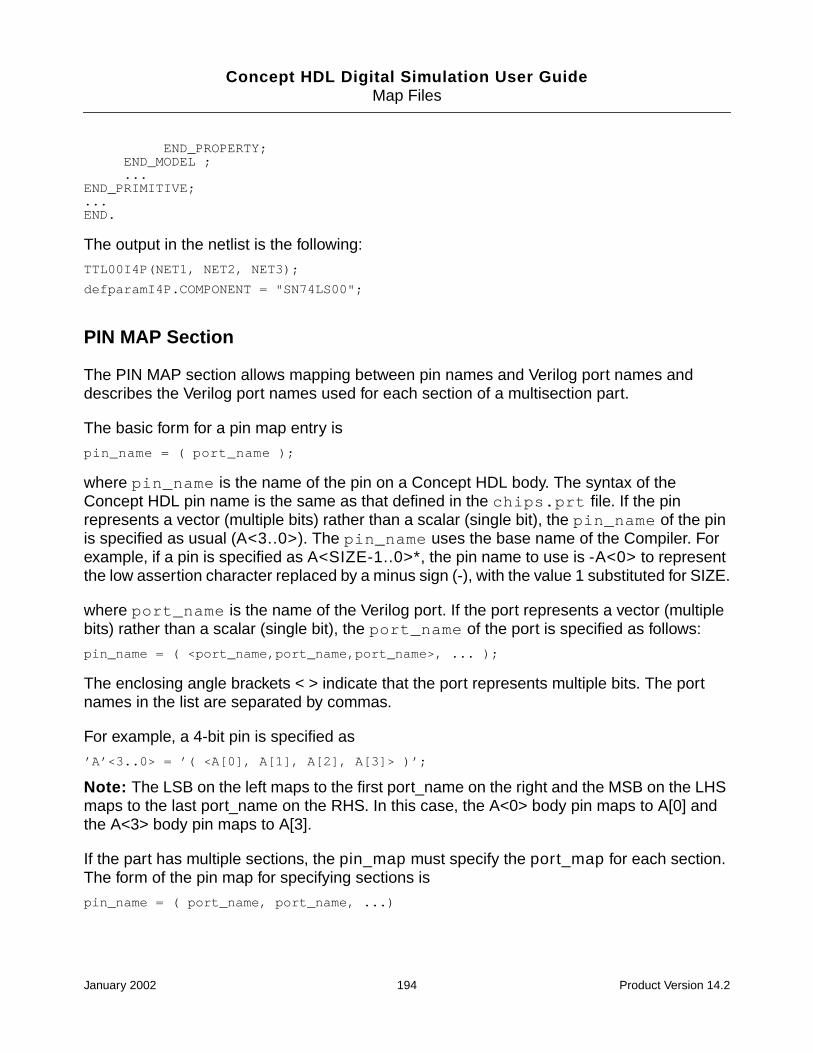
Concept HDL Digital Simulation User GuideMap Files
END_PROPERTY;END_MODEL ;...
END_PRIMITIVE;...END.
The output in the netlist is the following:
TTL00I4P(NET1, NET2, NET3);
defparamI4P.COMPONENT = "SN74LS00";
PIN MAP Section
The PIN MAP section allows mapping between pin names and Verilog port names anddescribes the Verilog port names used for each section of a multisection part.
The basic form for a pin map entry is
pin_name = ( port_name );
where pin_name is the name of the pin on a Concept HDL body. The syntax of theConcept HDL pin name is the same as that defined in the chips.prt file. If the pinrepresents a vector (multiple bits) rather than a scalar (single bit), the pin_name of the pinis specified as usual (A<3..0>). The pin_name uses the base name of the Compiler. Forexample, if a pin is specified as A<SIZE-1..0>*, the pin name to use is -A<0> to representthe low assertion character replaced by a minus sign (-), with the value 1 substituted for SIZE.
where port_name is the name of the Verilog port. If the port represents a vector (multiplebits) rather than a scalar (single bit), the port_name of the port is specified as follows:
pin_name = ( <port_name,port_name,port_name>, ... );
The enclosing angle brackets < > indicate that the port represents multiple bits. The portnames in the list are separated by commas.
For example, a 4-bit pin is specified as
’A’<3..0> = ’( <A[0], A[1], A[2], A[3]> )’;
Note: The LSB on the left maps to the first port_name on the right and the MSB on the LHSmaps to the last port_name on the RHS. In this case, the A<0> body pin maps to A[0] andthe A<3> body pin maps to A[3].
If the part has multiple sections, the pin_map must specify the port_map for each section.The form of the pin map for specifying sections is
pin_name = ( port_name, port_name, ...)
January 2002 194 Product Version 14.2

Concept HDL Digital Simulation User GuideMap Files
where port_name specifies the port name for the same pin but for a different section. Forexample, the output pin of a 74LS00 (a quad NAND gate) is specified as
’Y’<0> = ’(_4Y, _3Y, _2Y, _1Y)’;
You must specify four port names, because the part has four sections.
If a pin is common to each of the four sections, it must be given four port names; the portnames are all identical. For example, the clock pin of a 74LS273 (an octal register) is specifiedas follows:
’CLOCK’ = ’(CLK, CLK, CLK, CLK, CLK, CLK, CLK, CLK)’;
You must ensure that the port names are consistent for all ports of each section. Each namein the port name list specifies a different section.
For example, Concept HDL expects the second name in the list to correspond to the secondsection for every port of the part.
If a sectioned part has vectored pins, its port names are specified in a similar manner. Forexample, a 3-bit pin in a part with two sections might be specified as
’A’<2..0> = ’(<1A2, 1A1, 1A0>, <2A2, 2A1, 2A0>)’;
Asymmetrical parts have multiple sections that are functionally different, such as the74LS241, which has four buffers with active-high enables and four buffers with active-lowenables. A different version of the body is defined for each section in the part. The pins in thedifferent versions all have different pin names, so that a pin of a given name is present in onlyone section. The port map values for the pin specify all the sections of the part. Any port thatis not present in a given section is specified with a port name of 0.
For example, the pin map section for an 74LS241 is the following:
PIN_MAP;’Y1’<0> = ’(_1Y4, _1Y3, _1Y2, _1Y1, 0, 0, 0, 0 )’;’B’<0> = ’(_1A4, _1A3, _1A2, _1A1, 0, 0, 0, 0)’;’-OE1’ = ’(_1G_, _1G_, _1G_, _1G_, 0, 0, 0, 0)’;’Y0’<0> = ’(0, 0, 0, 0, _2Y4, _2Y3, _2Y2, _2Y1)’;’A’<0> = ’(0, 0, 0, 0, _2A4, _2A3, _2A2, _2A1)’;’OE0’ = ’(0, 0, 0, 0, _2G, _2G, _2G, _2G)’;
END_PIN;
The syntax for port mapping also allows for a more compact syntax. In addition to theprevious notation, the following features are also supported:
■ Subranges
The port map (Y4, Y3, Y2, Y1) is equivalent to (Y4..Y1).
■ Repeat sections
The port map (OE, OE, OE, OE) is equivalent to (OE * 4).
January 2002 195 Product Version 14.2
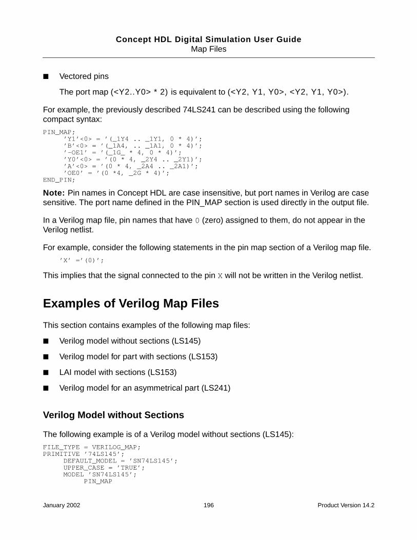
Concept HDL Digital Simulation User GuideMap Files
■ Vectored pins
The port map (<Y2..Y0> * 2) is equivalent to (<Y2, Y1, Y0>, <Y2, Y1, Y0>).
For example, the previously described 74LS241 can be described using the followingcompact syntax:
PIN_MAP;’Y1’<0> = ’(_1Y4 .. _1Y1, 0 * 4)’;’B’<0> = ’(_1A4, .. _1A1, 0 * 4)’;’-OE1’ = ’(_1G_ * 4, 0 * 4)’;’Y0’<0> = ’(0 * 4, _2Y4 .. _2Y1)’;’A’<0> = ’(0 * 4, _2A4 .. _2A1)’;’OE0’ = ’(0 *4, _2G * 4)’;
END_PIN;
Note: Pin names in Concept HDL are case insensitive, but port names in Verilog are casesensitive. The port name defined in the PIN_MAP section is used directly in the output file.
In a Verilog map file, pin names that have 0 (zero) assigned to them, do not appear in theVerilog netlist.
For example, consider the following statements in the pin map section of a Verilog map file.
’X’ =’(0)’;
This implies that the signal connected to the pin X will not be written in the Verilog netlist.
Examples of Verilog Map Files
This section contains examples of the following map files:
■ Verilog model without sections (LS145)
■ Verilog model for part with sections (LS153)
■ LAI model with sections (LS153)
■ Verilog model for an asymmetrical part (LS241)
Verilog Model without Sections
The following example is of a Verilog model without sections (LS145):
FILE_TYPE = VERILOG_MAP;PRIMITIVE ’74LS145’;
DEFAULT_MODEL = ’SN74LS145’;UPPER_CASE = ’TRUE’;MODEL ’SN74LS145’;
PIN_MAP
January 2002 196 Product Version 14.2

Concept HDL Digital Simulation User GuideMap Files
’I’<3> = ’(D)’;’I’<2> = ’(C)’;’I’<1> = ’(B)’;’I’<0> = ’(A)’;’-Y9’ = ’(_9)’;’-Y8’ = ’(_8)’;’-Y7’ = ’(_7)’;’-Y6’ = ’(_6)’;’-Y5’ = ’(_5)’;’-Y4’ = ’(_4)’;’-Y3’ = ’(_3)’;’-Y2’ = ’(_2)’;’-Y1’ = ’(_1)’;’-Y0’ = ’(_0)’;
END_PIN;END_MODEL;
END_PRIMITIVE;END.
The output in the netlist is the following:
SN74LS145 PAGE1_5P (.D(LS145_I[3]),
.C(LS145_I[2]),
.B(LS145_I[1]),
.A(LS145_I[0]),
._9(LS145_Y9),
._8(LS145_Y8),
.....
._0(LS145_Y0));
Verilog Model with Sections
The following example is a map file for a Verilog model for a part with sections (LS153):
FILE_TYPE = VERILOG_MAP;PRIMITIVE ’74LS153’;
DEFAULT_MODEL = ’SN74LS153’;UPPER_CASE = ’TRUE’;MODEL ’SN74LS153’;
PIN_MAP’Y’<0> = ’(_2Y, _1Y)’;’S’<1> = ’(B, B)’;’S’<0> = ’(A, A)’;’I3’<0> = ’(_2C3, _1C3)’;’I2’<0> = ’(_2C2, _1C2)’;’I1’<0> = ’(_2C1, _1C1)’;’I0’<0> = ’(_2C0, _1C0)’;’-E’ = ’(_2G_, _1G_);
END_PIN;END_MODEL;
END_PRIMITIVE;END.
The output in the netlist is the following:
January 2002 197 Product Version 14.2

Concept HDL Digital Simulation User GuideMap Files
SN74L3153I2P(._1Y(LS153_Y),
.B(LS153_S[1]),
.A(LS153_S[0]),
._1C3(LS153_I3),
._1C2(LS153_I2),
._1C1(LS153_I1),
._IC0(LS153_I0),
._1G_(LS153_E));
Note: To operate on a part that contains sections, Concept HDL must have a chips.prtfile. The Cadence standard parts library comes with a chips.prt file. So do not modify it.
SWIFT Model with Sections
The following example is of a SWIFT model with sections (LS153):
FILE_TYPE = VERILOG_MAP;PRIMITIVE ’74LS153’;
DEFAULT_MODEL = ’TTL153’;MODEL ’TTL153’;
PROPERTYCOMPONENT = ’SN74LS153’;
END_PROPERTY;PIN_MAP’Y’<0> = ’(Y2, Y1)’;
’S’<1> = ’(B, B)’;’S’<0> = ’(A, A)’;’I3’<0> = ’(C23, C13)’;’I2’<0> = ’(C22, C12)’;’I1’<0> = ’(C21, C11)’;’I0’<0> = ’(C20, C10)’;’-E’ = ’(G2, G1);
END_PIN;END_MODEL;
END_PRIMITIVE;END.
The output in the netlist is the following:
TTL153 PAGE1_2P (.A(LS153.S[0],
.B(LS153_S[1]),
.C10(L153_I0),
.c11(LS153_I1),
.c12(LS153_I2),
.C13(LS153_I3),
.G1(LS153_E),
.Y1(LS153_Y));
defparam PAGE1_2P.COMPONENT = "SN74LS153";
January 2002 198 Product Version 14.2

Concept HDL Digital Simulation User GuideMap Files
Note: To operate on a part that contains sections, Concept HDL must have a chips.prtfile. The standard parts library provided by Cadence comes with a chips.prt file, so donot modify it.
VHDL Map File
The VHDL map file (vhdl.map) specifies pin-to-port mapping information and theparameters to be passed to the VHDL descriptions. Generally the file is only necessary forexternally defined libraries. The file can also be used for user-defined VHDL descriptions, butthis is not necessary unless the symbol names differ from the model names.
The VHDL map file must be located under the directory used to stop the expansion and mustbe called vhdl.map.
VHDL Map File Format
The following is an example of a VHDL map file:
FILE_TYPE = VHDL_MAP;PRIMITIVE ’primitive_name’ [ , ’primitive_name’ ... ];
DEFAULT_MODEL = ’architecture_name’;UPPER_CASE= [TRUE|FALSE];MODEL ’vhdl_name’ [ , ’vhdl_name’ ... ];
PROPERTYPORT_ORDER = ‘(port1, port2, ... )’;property_1 = value_1;...property_n = value_n;
END_PROPERTY;
PIN_MAP‘body_pin_name_1’ = ‘vdl_port_name_1’;...‘body_pin_name_n’ = ‘vhdl_port_name_n’;
END_PIN;END_MODEL;MODEL ’vhdl_name’ [, ’vhdl_name’ ... ];
...END_MODEL;
END_PRIMITIVE;
PRIMITIVE ’primitive_name’ [ , ’primitive_name’ ... ];...
END_PRIMITIVE;END.
PRIMITIVE Section
The PRIMITIVE section describes all the information related to a specific primitive. The nameused for the primitive is either the body name used in Concept HDL or the part name specified
January 2002 199 Product Version 14.2

Concept HDL Digital Simulation User GuideMap Files
in the PART_NAME property. For example, in the lsttl library the LS00 has a PART_NAME =74LS00 property and the primitive name 74LS00. You can modify this name by adding aPACK_TYPE property on a specific instance. For example, if an instance of an LS00 has aPACK_TYPE = DIP property, the primitive name is 74LS00_DIP.
In the VHDL map file you can describe several PRIMITIVE sections for different primitivenames. For example, you can describe a primitive section for a 74LS00, another section fora 74LS00_DIP, and a third section for a 74LS00_SOIC. Concept HDL selects the entry basedon the primitive name for a specific instance. If there is no description for a primitive nameobtained with the PACK_TYPE property, Concept HDL looks for an entry without thePACK_TYPE suffix.
For example, if there is no entry for a primitive called 74LS00_LCC, Concept HDL looks for a74LS00 entry; if not found, Concept HDL generates an error. In most cases, Concept HDLlets you describe only one primitive section if mapping information is independent of thePACK_TYPE.
You can specify two special properties in the PRIMITIVE section:
■ Use the DEFAULT_MODEL property to specify the default name of the VHDL model.
This default name is used by Concept HDL as a default when no VHDL_MODELproperty has been used on an instance.
■ Use the UPPER_CASE property to specify that a VHDL description name must be madeuppercase in the output netlist.
By default, all description names are lowercase unless changed by an UPPER_CASE =TRUE property.
Note: If the UPPER_CASE property is not specified in the map file, the VHDLdescription names are output as is in the netlist.
The following is an example of the PRIMITIVE section for an LS00:
FILE_TYPE = VHDL_MAP;PRIMITIVE ’74LS00’ , ’74LS00_DIP’;
DEFAULT_MODEL = ’SN74LS00’;UPPER_CASE = ’TRUE’;...
END_PRIMITIVE;END.
MODEL Section
The MODEL section contains all information specific to one or several VHDL descriptions.You can specify several MODEL sections inside one PRIMITIVE section if you have several
January 2002 200 Product Version 14.2

Concept HDL Digital Simulation User GuideMap Files
VHDL descriptions available from a library that need different mapping information. At leastone MODEL section must be described in the PRIMITIVE section.
The following is an example of MODEL section for an LS00:
FILE_TYPE = VHDL_MAP;PRIMITIVE ’74LS00’;
....MODEL ’SN74LS00’, ’SIG74LS00’ ;
...END_MODEL
END_PRIMITIVE;...END.
PROPERTY Section
The PROPERTY section inside the MODEL section specifies local properties that apply toonly one specific VHDL description. The PROPERTY section is optional.
You can add as many properties as you want. Properties defined in this section are used byConcept HDL to specify which specific body properties Concept HDL needs to look for. Forexample, if a property OSC is defined in this section, Concept HDL searches for this propertyon all instances of this part in the design. If the property is found, Concept HDL outputs theproperty as a parameter for the description using generics in the VHDL netlist.
Two important properties are usually defined in this section:
■ The VHDL_NAME property specifies the name of the VHDL model.
Internally, all names for descriptions are lowercase.
If the description you are using is either uppercase or contains a mixture of lower- anduppercase characters, use the VHDL_NAME property to specify the final name that willbe output in the netlist.
■ The PORT_ORDER property specifies the order of the VHDL model ports.
For more information on the PORT_ORDER property, see Appendix E, “SimulationProperties.”
The following is an example of the PROPERTY section for an LS00:
FILE_TYPE = VHDL_MAP;PRIMITIVE ’74LS00’;
....DEFAULT_MODEL = ’SN74LS00’;
PROPERTYPORT_ORDER = ’(A_1, B_1, Y_1)’;VHDL_NAME = ’SN74LS00’;
END_PROPERTY;
January 2002 201 Product Version 14.2

Concept HDL Digital Simulation User GuideMap Files
END_MODEL...
END_PRIMITIVE;...END.
PIN MAP Section
The PIN MAP section allows mapping between pin names and VHDL port names, anddescribes the VHDL port names used for each section of a part that has more than onesection.
The basic form for a pin map entry is
pin_name = ’’( port_name )’’;
The pin_name is the name of the pin on a Concept HDL body. If the pin represents a vector(multiple bits) rather than a scalar (single bit), the pin_name of the pin is specified as usual(A<3..0>). The pin_name uses the base name of the actual pin. For example, if a pin isspecified as A<SIZE-1..0>* the pin name to use is -A<0> to represent the low assertioncharacter replaced by a minus sign (-), with the value 1 substituted for SIZE.
The port_name is the name of the VHDL port. If the port represents a vector (multiple bits)rather than a scalar (single bit), specify the port name as follows:
pin_name = ’’(<port_name,port_name,port_name>, ...)’’;
The enclosing angle brackets < > indicate that the port represents multiple bits. The portnames in the list are separated by commas.
For example, a 4-bit pin is specified as
A<3..0> = ’’( <A3, A2, A1, A0> )’’;
If the part has multiple sections, the pin_map must specify the port_map for each section.The form of the pin map for specifying sections is
pin_name = ’’( port_name, port_name, ...)’’;
where port_name specifies the port name for the same pin but for a different section. Forexample, the output pin of an 74LS00 (a quad NAND gate) is specified as
Y<0> = ’’(Y_4, Y_3, Y_2, Y_1)’’;
There must be four port names specified because the part has four sections.
If a pin is common to each of the four sections, it must be given four port names; the portnames are all identical. For example, the clock pin of a 74LS273 (an octal register) is specifiedas follows:
CLOCK = (CLK, CLK, CLK, CLK, CLK, CLK, CLK, CLK);
January 2002 202 Product Version 14.2

Concept HDL Digital Simulation User GuideMap Files
You must ensure that the port names are consistent for all ports of each section. Each namein the port name list specifies a different section. Concept HDL expects the second name inthe list, for example, to correspond to the second section for every port of the part.
If a sectioned part has vectored pins, its port names are specified in a similar manner. Forexample, a 3-bit pin in a part with two sections might be specified as
A<2..0> = (<A1_2, A1_1, A1_0>, <A2_2, A2_1, A2_0>);
Asymmetrical parts have multiple sections that are functionally different, such as the74LS241, which has four buffers with active-high enables and four buffers with active-lowenables. A different version of the body is defined for each section in the part. The pins in thedifferent versions all have different pin names, so that a pin of a given name is only presentin one section. The port map values for the pin specify all the sections of the part. Any portthat is not present in a given section is specified with a port name of 0.
For example, the pin map section for 74LS241 is the following:
PIN_MAP;’Y1’<0> = ’(Y1_4,Y1_3,Y1_2,Y1_1,0,0,0,0)’;’B’<0> = ’(A1_4,A1_3,A1_2,A1_1,0,0,0,0)’;’-OE1’ = ’(G1,G1,G1,G1,0,0,0,0)’;’Y0’<0> = ’(0,0,0,0,Y2_4,Y2_3,Y2_2,Y2_1)’;’A’<0> = ’(0,0,0,0,A2_4,A2_3,A2_2,A2_1)’;’OE0’ = ’(0,0,0,0,G2,G2,G2,G2)’;
END_PIN;
The syntax for port mapping also allows for a more compact syntax. In addition to theprevious notation, the following features are also supported:
■ Subranges
Port map (Y4, Y3, Y2, Y1) is equivalent to (Y4..Y1)
■ Repeat sections
Port map (OE, OE, OE, OE) is equivalent to (OE * 4)
■ Vectored pins
Port map (<Y2..Y0> * 2) is equivalent to (<Y2, Y1, Y0>, <Y2, Y1, Y0>)
For example, the previously described 74LS241 can be described using the followingcompact syntax:
PIN_MAP;’Y1’<0> = ’(Y1_4 .. Y1_1,0 * 4)’;’B’<0> = ’(A1_4 .. A1_1,0 * 4)’;’-OE1’ = ’(G1 * 4,0 * 4)’;’Y0’<0> = ’(0 * 4,Y2_4 .. Y2_1)’;’A’<0> = ’(0 * 4,A2_4 .. A2_1)’;’OE0’ = ’(0 * 4,G2 * 4)’;
END_PIN;
January 2002 203 Product Version 14.2
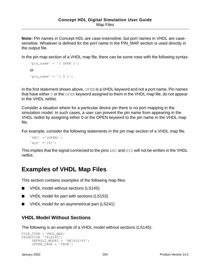
Concept HDL Digital Simulation User GuideMap Files
Note: Pin names in Concept HDL are case-insensitive, but port names in VHDL are case-sensitive. Whatever is defined for the port name in the PIN_MAP section is used directly inthe output file.
In the pin map section of a VHDL map file, there can be some rows with the following syntax:
’pin_name’ = ’( OPEN )’;
or
’pin_name’ = ’( 0 )’;
In the first statement shown above, OPEN is a VHDL keyword and not a port name. Pin namesthat have either 0 or the OPEN keyword assigned to them in the VHDL map file, do not appearin the VHDL netlist.
Consider a situation where for a particular device pin there is no port mapping in thesimulation model. In such cases, a user can prevent the pin name from appearing in theVHDL netlist by assigning either 0 or the OPEN keyword to the pin name in the VHDL mapfile.
For example, consider the following statements in the pin map section of a VHDL map file.
’ABC’ =’(OPEN)’;
’xyz’ =’(0)’;
This implies that the signal connected to the pins ABC and XYZ will not be written in the VHDLnetlist.
Examples of VHDL Map Files
This section contains examples of the following map files:
■ VHDL model without sections (LS145)
■ VHDL model for part with sections (LS153)
■ VHDL model for an asymmetrical part (LS241)
VHDL Model Without Sections
The following is an example of a VHDL model without sections (LS145):
FILE_TYPE = VHDL_MAP;PRIMITIVE ’74LS145’;
DEFAULT_MODEL = ’SN74LS145’;UPPER_CASE = ’TRUE’;
January 2002 204 Product Version 14.2
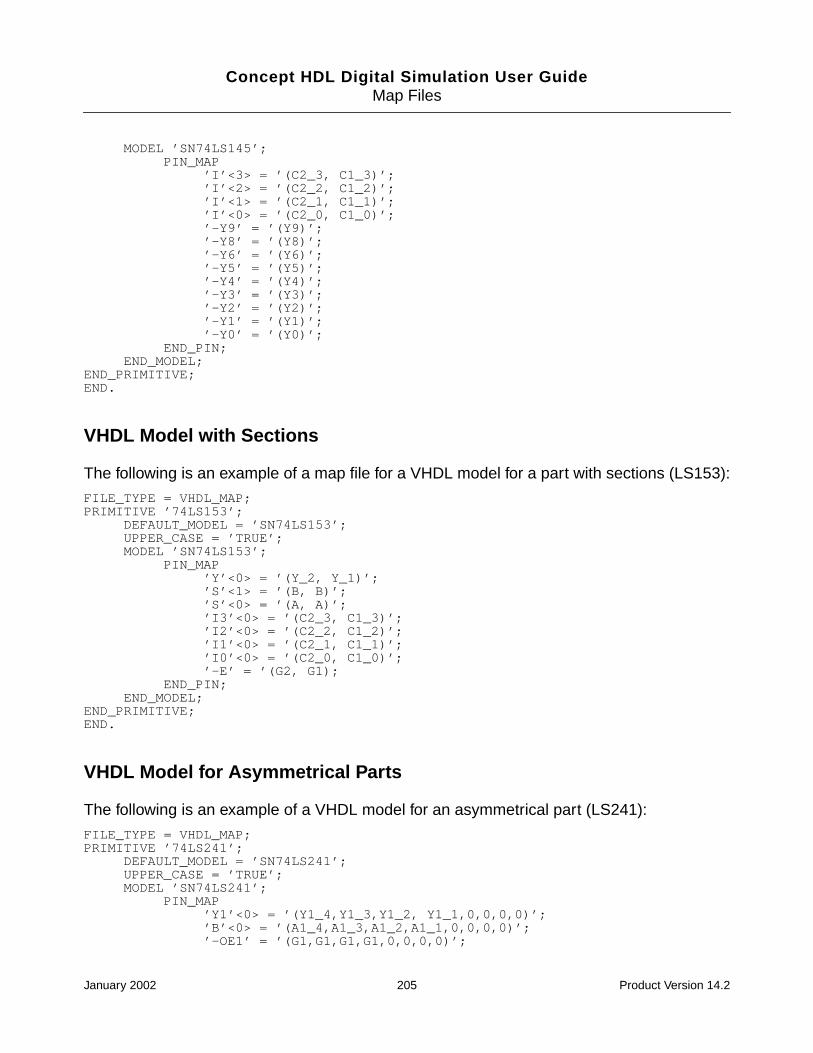
Concept HDL Digital Simulation User GuideMap Files
MODEL ’SN74LS145’;PIN_MAP
’I’<3> = ’(C2_3, C1_3)’;’I’<2> = ’(C2_2, C1_2)’;’I’<1> = ’(C2_1, C1_1)’;’I’<0> = ’(C2_0, C1_0)’;’-Y9’ = ’(Y9)’;’-Y8’ = ’(Y8)’;’-Y6’ = ’(Y6)’;’-Y5’ = ’(Y5)’;’-Y4’ = ’(Y4)’;’-Y3’ = ’(Y3)’;’-Y2’ = ’(Y2)’;’-Y1’ = ’(Y1)’;’-Y0’ = ’(Y0)’;
END_PIN;END_MODEL;
END_PRIMITIVE;END.
VHDL Model with Sections
The following is an example of a map file for a VHDL model for a part with sections (LS153):
FILE_TYPE = VHDL_MAP;PRIMITIVE ’74LS153’;
DEFAULT_MODEL = ’SN74LS153’;UPPER_CASE = ’TRUE’;MODEL ’SN74LS153’;
PIN_MAP’Y’<0> = ’(Y_2, Y_1)’;’S’<1> = ’(B, B)’;’S’<0> = ’(A, A)’;’I3’<0> = ’(C2_3, C1_3)’;’I2’<0> = ’(C2_2, C1_2)’;’I1’<0> = ’(C2_1, C1_1)’;’I0’<0> = ’(C2_0, C1_0)’;’-E’ = ’(G2, G1);
END_PIN;END_MODEL;
END_PRIMITIVE;END.
VHDL Model for Asymmetrical Parts
The following is an example of a VHDL model for an asymmetrical part (LS241):
FILE_TYPE = VHDL_MAP;PRIMITIVE ’74LS241’;
DEFAULT_MODEL = ’SN74LS241’;UPPER_CASE = ’TRUE’;MODEL ’SN74LS241’;
PIN_MAP’Y1’<0> = ’(Y1_4,Y1_3,Y1_2, Y1_1,0,0,0,0)’;’B’<0> = ’(A1_4,A1_3,A1_2,A1_1,0,0,0,0)’;’-OE1’ = ’(G1,G1,G1,G1,0,0,0,0)’;
January 2002 205 Product Version 14.2

Concept HDL Digital Simulation User GuideMap Files
’Y0’<0> = ’(0,0,0,0,Y2_4,Y2_3,Y2_2,Y2_1)’;’A’<0> = ’(0,0,0,0,A2_4,A2_3,A2_2,A1)’;’OE0’ = ’(0,0,0,0,G_2,G_2,G_2,G_2)’;
END_PIN;END_MODEL;
END_PRIMITIVE;END.
January 2002 206 Product Version 14.2

Concept HDL Digital Simulation User Guide
GSDF Files
Tools used before or after simulation in the design process, such as the Allegro layout tool,generate Standard Delay Format (SDF) files. SDF files can include timing information for thefollowing:
■ delays for module iopaths, devices, ports, and interconnect
■ timing checks.
■ timing constraints.
■ scaling, environmental, technology, and user defined parameters.
The SDF Annotator annotates timing data to the simulator. Timing data in an SDF file can beof two types:
■ Logical: This could be an ASIC SDF file with the components provided by the vendor.
■ Physical: This comes from the Allegro SDF file
Note: The SDF annotation that you can perform from the Concept HDL Digital SimulationInterface is only for the interconnect delays in the Allegro SDF file. The Allegro SDF file isgenerated using the Allegro a2sdf wire delay extract utility. The SDF Annotator reads thespecified Allegro SDF file and annotates the timing data to the simulator. For more informationon the SDF Annotator and SDF files, see the SDF Annotator Guide.
$SDF_annotate
The $SDF_annotate system task invokes the SDF Annotator. You can run the SDFAnnotator any number of times from the simulator. You can call this system task interactivelyor by specifying it in the initial block of the stimulus file you use for simulating your design. Ifyou want to allow SDF annotation at times other than time 0, use the +annotate_any_timeplus option in the command line. The $SDF_annotate arguments are shown in the followingsyntax:
$SDF_annotate ( <"SDF_file">, <module_instance>?,
<"config_file">?, <"log_file">?, <"mtm_spec">?,
January 2002 207 Product Version 14.2

Concept HDL Digital Simulation User GuideSDF Files
<"scale_factors">?, <"scale_type">? );
All arguments other than the initial SDF_file are optional and all the arguments exceptmodule_instancemust be in quotation marks. If you omit optional arguments, the commasthat would have surrounded them must remain, unless the omitted arguments areconsecutive and include the last argument. In that case the closing parenthesis can follow thelast argument present.
INTERCONNECT Keyword
The INTERCONNECT keyword specifies estimated or actual delays in the wire paths betweendevices. The syntax is as follows:
(INTERCONNECT port_path1 port_path2 delay_list)
In the following example, the delay_list consists of two min:typ:max triplets specifyingthe delays for rise and fall transitions.
(INSTANCE x)
(DELAY
(ABSOLUTE
(INTERCONNECT y.z.o1 w.i3 (5:6:7) (5.5:6:6.5))
)
)
Keyword Argument Description
port_path1 Output or inout port. Where applicable, a port path can havearray index (for example, x.y[3].p)
port_path2 Input or inout port. Where applicable, a port path can have arrayindex (for example, x.y[3].p)
delay_list Interconnect delay between the output and inout ports. Uniquedelays can be specified for multi-source nets. The delay can alsoinclude optional reject and error limits.
January 2002 208 Product Version 14.2

Concept HDL Digital Simulation User GuideSDF Files
INTERCONNECT delays are mapped to Module Input Port Delays (MIPDs) by default.MIPDs use inertial delays. Verilog-XL has interconnect transport delay functionality with pulsecontrol, which is enabled by using the +transport_int_delays and/or the+multisource_int_delays plus options.
The simulator generates Single-source Interconnect Transport Delays (SITDs) or Multi-source Interconnect Transport Delays (MITDs), as shown in the following table:
To specify optional reject and error limits, enclose the entire delay_list in parentheses andenclose the delay, reject limit, and error limit in their own parentheses. For example, thefollowing command specifies one delay. For all transitions, the delay is 12, the reject limit is6, and the error limit is 10.
(INTERCONNECT A B ((12:12:12) (6:6:6) (10:10:10)))
To specify that a current delay is to be maintained, use an empty set of parentheses. Forexample, the following INTERCONNECT statement annotates a delay of 3:5:7 and an errorlimit of 2:3:6, while keeping the current setting for the reject limit.
(INTERCONNECT A B ((3:5:7) ( ) (2:3:6)))
Interconnect Example
The following commented examples illustrate the syntax for INTERCONNECT.
Plus Option Single-source Nets Multi-source Nets
+transport_int_delays SITD SITD
+multisource_int_delays MIPD MITD
Both plus option SITD MITD
Neither plus option MIPD MIPD
January 2002 209 Product Version 14.2

Concept HDL Digital Simulation User GuideSDF Files
(INTERCONNECT A B (12:12:12))
// Delay=12 for all transitions.
// Reject and error limits are not specified,
// and are set equal to the delay.
(INTERCONNECT A B ((12:12:12) (6:6:6) (10:10:10)))
// Delay=12, reject=6, error=10
// for all transitions.
(INTERCONNECT A B ((12:12:12) ( ) (10:10:10)))
// Delay=12, reject=current value,
// error=10 for all transitions.
(INTERCONNECT A B ((12:12:12) (10:10:10)))
// Delay=12 and reject=10 for all transitions.
// Error limit is not included,
// so it is set equal to reject limit.
(INTERCONNECT A B (12:12:12)
((10:10:10) (5:5:5) (9:9:9)))
// Delay=12, reject=12, error=12
// for rise transition.
// Delay=10, reject=5, error=9
// for fall transition.
(INTERCONNECT A B ((5:5:5) (2:2:2) (3:3:3))
((6:6:6) (3:3:3) (4:4:4))
((15:15:15) (7:7:7) (10))
((14:14:14) (6:6:6) (9:9:9))
((12:12:12) (7:7:7) (9:9:9))
((13:13:13) (5:5:5) (8:8:8)))
// Delay=5, reject=2, error=3 for 01 transition.
// Delay=6, reject=3, error=4 for 10 transition.
// Delay=15, reject=7, error=10 for 0Z transition.
// Delay=14, reject=6, error=9 for Z1 transition.
// Delay=12, reject=7, error=9 for 1Z transition.
// Delay=13, reject=5, error=8 for Z0 transition.
(INTERCONNECT A D ((5:5:5) (2:2:2) (3:3:3)))
(INTERCONNECT B D ((6:6:6) (3:3:3) (4:4:4)))
(INTERCONNECT C D ((7:7:7) (4:4:4) (5:5:5)))
// Unique delays, reject limits, and error limits
// for multi-source net
January 2002 210 Product Version 14.2

Concept HDL Digital Simulation User Guide
HFiles Created in Run Directory
When you run the simulation process, some files are created in the run directory that youspecify for the simulation. These files are described below:
■ Files used for Compiling the Design
❑ script.cmd on page 212
❑ verilog.cmd on page 213
❑ compilescript on page 213
❑ <design_name>.f on page 215
■ Netlist Files
❑ <design_name>.v on page 216
❑ <design_name>.vhd on page 216
■ Log Files
❑ netassembler.log on page 216
❑ ncvlog.log on page 217
❑ ncvhdl.log on page 217
❑ ncelab.log on page 217
❑ ncsim.log on page 217
❑ verilog.log on page 217
❑ detail.log on page 217
❑ HierEditor.log on page 217
■ Other Files
❑ hdl.var on page 218
January 2002 211 Product Version 14.2

Concept HDL Digital Simulation User GuideFiles Created in Run Directory
script.cmd
This file is automatically generated when you run the simulation interface for NC Verilog andNC VHDL. This file contains the commands to compile the following:
■ Global module
■ Design modules (with schematic views)
■ Testbench module
■ Configuration (VHDL only)
This file is automatically executed if the Generate Compilescript check box is not selectedin the Netlist tab of the simulation interface setup dialog box for NC Verilog and NC VHDL.
Sample script.cmd file for NC Verilog Simulation Interface
In the sample script.cmd file given below, risccpu is the name of the design.
ncvlog -hdlvar ./worklib/risccpu/cfg_verilog/sim1/hdl.var -viewrisccpu_cfg_verilog -w worklib /net/foo/<project_directory>/worklib/glbl/risccpu_cfg_verilog/verilog.v
ncvlog -hdlvar ./worklib/risccpu/cfg_verilog/sim1/hdl.var -view sim_sch_1 -wworklib /net/foo/<project_directory>/worklib/risccpu/sim_sch_1/verilog.v
ncvlog -hdlvar ./worklib/risccpu/cfg_verilog/sim1/hdl.var -viewrisccpu_sim_sch_1 -w worklib ./worklib/testfixture/risccpu_sim_sch_1/verilog.v
Sample script.cmd file for NC VHDL Simulation Interface
In the sample script.cmd file given below, sysctrl is the name of the top level design.
ncvhdl -Append_log -logfile ./worklib/sysctrl/cfg_vhdl/sim1/ncvhdl.log -wsysctrl_lib /net/foo/<project_directory>/worklib/glbl/sysctrl_cfg_vhdl/vhdl.vhd
ncvhdl -Append_log -logfile ./worklib/sysctrl/cfg_vhdl/sim1/ncvhdl.log -wsysctrl_lib /net/foo/<project_directory>/worklib/sysctrl/entity/vhdl.vhd
ncvhdl -Append_log -logfile ./worklib/sysctrl/cfg_vhdl/sim1/ncvhdl.log -wsysctrl_lib /net/foo/<project_directory>/worklib/sysctrl/sim_sch_1/vhdl.vhd
ncvhdl -Append_log -logfile ./sysctrl/sysctrl/cfg_vhdl/sim1/ncvhdl.log -wsysctrl_lib /net/foo/<project_directory>/worklib/sysctrl_cfg/configuration/vhdl.vhd
ncvhdl -Append_log -logfile ./sysctrl/sysctrl/cfg_vhdl/sim1/ncvhdl.log -wsysctrl_lib /net/foo/<project_directory>/worklib/testfixture/entity/vhdl.vhd
January 2002 212 Product Version 14.2

Concept HDL Digital Simulation User GuideFiles Created in Run Directory
ncvhdl -Append_log -logfile ./sysctrl/sysctrl/cfg_vhdl/sim1/ncvhdl.log -USE5X-w sysctrl_lib /net/foo/<project_directory>/worklib/testfixture/vhdl_rtl/vhdl.vhd
verilog.cmd
The verilog.cmd file contains the Verilog-XL command line options corresponding to theoptions you have specified in the Simulation tab and Library tab of the simulation interfacesetup dialog box for Verilog-XL. This file is automatically created every time you run thesimulation.
For example, if you have specified Delay Mode as Path in the Simulation tab of thesimulation interface setup dialog box for Verilog-XL, the following equivalent command lineoption is written in the verilog.cmd file:
+delay_mode_path
Sample verilog.cmd file
+max_err_count+20
+typdelays
+delay_mode_path
+sdf_verbose
-y ./cell_lib/verilogmodels
+libext+.v+.verilog
compilescript
The compilescript file is a superset of the script.cmd file. It contains the commands to compileother components in the design such as components bound to wrapper view, RTL view, etc.,in addition to the contents of script.cmd file.
This file is generated if you select the Generate Compilescript check box in the Netlist tabof the simulation interface setup dialog box for NC Verilog and NC VHDL. This file is alsoautomatically executed if the Generate Compilescript check box is selected in the Netlisttab of the simulation interface setup dialog box for NC Verilog and NC VHDL.
Sample compilescript file for NC Verilog Simulation Interface
In the sample compilescript file given below, risccpu is the name of the top level design.
January 2002 213 Product Version 14.2

Concept HDL Digital Simulation User GuideFiles Created in Run Directory
ncvlog -hdlvar ./worklib/risccpu/cfg_verilog/sim1/hdl.var -viewrisccpu_cfg_verilog -w worklib /net/foo/<project_directory>/worklib/glbl/risccpu_cfg_verilog/verilog.v
ncvlog -hdlvar ./worklib/risccpu/cfg_verilog/sim1/hdl.var -view vlog_behavioral-w worklib /net/foo/<project_directory>/worklib/addrmux/vlog_behavioral/verilog.v
ncvlog -hdlvar ./worklib/risccpu/cfg_verilog/sim1/hdl.var -view vlog_behavioral-w worklib /net/foo/<project_directory>/worklib/riscalu/vlog_behavioral/verilog.v
ncvlog -hdlvar ./worklib/risccpu/cfg_verilog/sim1/hdl.var -view vlog_structural-w worklib /net/foo/<project_directory>/worklib/register/vlog_structural/verilog.v
ncvlog -hdlvar ./worklib/risccpu/cfg_verilog/sim1/hdl.var -view vlog_behavioral-w worklib /net/foo/<project_directory>/worklib/counter/vlog_behavioral/verilog.v
ncvlog -hdlvar ./worklib/risccpu/cfg_verilog/sim1/hdl.var -view vlog_behavioral-w worklib /net/foo/<project_directory>/worklib/control/vlog_behavioral/verilog.v
ncvlog -hdlvar ./worklib/risccpu/cfg_verilog/sim1/hdl.var -view vlog_behavioral-w worklib /net/foo/<project_directory>/worklib/mem/vlog_behavioral/verilog.v
ncvlog -hdlvar ./worklib/risccpu/cfg_verilog/sim1/hdl.var -view vlog_behavioral-w worklib /net/foo/<project_directory>/worklib/clkgen/vlog_behavioral/verilog.v
ncvlog -hdlvar ./worklib/risccpu/cfg_verilog/sim1/hdl.var -view vlog_behavioral-w worklib /net/foo/<project_directory>/worklib/datactrl/vlog_behavioral/verilog.v
ncvlog -hdlvar ./worklib/risccpu/cfg_verilog/sim1/hdl.var -view sim_sch_1 -wworklib /net/foo/<project_directory>/worklib/risccpu/sim_sch_1/verilog.v
ncvlog -hdlvar ./worklib/risccpu/cfg_verilog/sim1/hdl.var -viewrisccpu_sim_sch_1 -w worklib ./worklib/testfixture/risccpu_sim_sch_1/verilog.v
Sample compilescript file for NC VHDL Simulation Interface
In the sample compilescript file given below, sysctrl is the name of the top level design.
ncvhdl -Append_log -logfile ./worklib/sysctrl/cfg_vhdl/sim1/ncvhdl.log -wsysctrl_lib /net/foo/<project_directory>/worklib/glbl/sysctrl_cfg_vhdl/vhdl.vhd
ncvhdl -Append_log -logfile ./worklib/sysctrl/cfg_vhdl/sim1/ncvhdl.log -wsmall_medium_ics_32 /net/foo/<project_directory>/small_medium_ics_32/74f10/entity/vhdl.vhd
January 2002 214 Product Version 14.2

Concept HDL Digital Simulation User GuideFiles Created in Run Directory
ncvhdl -Append_log -logfile ./worklib/sysctrl/cfg_vhdl/sim1/ncvhdl.log -wsmall_medium_ics_32 /net/foo/<project_directory>/small_medium_ics_32/74f10/vhdl_lib/vhdl.vhd
ncvhdl -Append_log -logfile ./worklib/sysctrl/cfg_vhdl/sim1/ncvhdl.log -wsmall_medium_ics_32 /net/foo/<project_directory>/small_medium_ics_32/74f02/entity/vhdl.vhd
ncvhdl -Append_log -logfile ./worklib/sysctrl/cfg_vhdl/sim1/ncvhdl.log -wsmall_medium_ics_32 /net/foo/<project_directory>/small_medium_ics_32/74f02/vhdl_lib/vhdl.vhd
ncvhdl -Append_log -logfile ./worklib/sysctrl/cfg_vhdl/sim1/ncvhdl.log -wsmall_medium_ics_32 /net/foo/<project_directory>/small_medium_ics_32/74ac74/entity/vhdl.vhd
ncvhdl -Append_log -logfile ./worklib/sysctrl/cfg_vhdl/sim1/ncvhdl.log -wsmall_medium_ics_32 /net/foo/<project_directory>/small_medium_ics_32/74ac74/vhdl_lib/vhdl.vhd
ncvhdl -Append_log -logfile ./worklib/sysctrl/cfg_vhdl/sim1/ncvhdl.log -wsmall_medium_ics_32 /net/foo/<project_directory>/small_medium_ics_32/74als08/entity/vhdl.vhd
ncvhdl -Append_log -logfile ./worklib/sysctrl/cfg_vhdl/sim1/ncvhdl.log -wsmall_medium_ics_32 /net/foo/<project_directory>/small_medium_ics_32/74als08/vhdl_lib/vhdl.vhd
ncvhdl -Append_log -logfile ./worklib/sysctrl/cfg_vhdl/sim1/ncvhdl.log -wsysctrl_lib /net/foo/<project_directory>/worklib/sysctrl/entity/vhdl.vhd
ncvhdl -Append_log -logfile ./worklib/sysctrl/cfg_vhdl/sim1/ncvhdl.log -wsysctrl_lib /net/foo/<project_directory>/worklib/sysctrl/sim_sch_1/vhdl.vhd
ncvhdl -Append_log -logfile ./worklib/sysctrl/cfg_vhdl/sim1/ncvhdl.log -wsysctrl_lib /net/foo/<project_directory>/worklib/sysctrl_cfg/configuration/vhdl.vhd
ncvhdl -Append_log -logfile ./worklib/sysctrl/cfg_vhdl/sim1/ncvhdl.log -wsysctrl_lib /net/foo/<project_directory>/worklib/testfixture/entity/vhdl.vhd
ncvhdl -Append_log -logfile ./worklib/sysctrl/cfg_vhdl/sim1/ncvhdl.log -USE5X-w sysctrl_lib /net/foo/<project_directory>/worklib/testfixture/vhdl_rtl/vhdl.vhd
<design_name>.f
This file is generated if you select the Regenerate Configuration check box in the Netlisttab of the simulation interface setup dialog box for Verilog-XL. This file contains the paths toall the cells used in the design. This file is used by Verilog-XL to compile the design.
January 2002 215 Product Version 14.2

Concept HDL Digital Simulation User GuideFiles Created in Run Directory
Sample compilescript file for Verilog-XL Simulation Interface
In the sample <design_name>.f file given below, risccpu is the name of the top leveldesign.
net/foo/<project_directory>/worklib/addrmux/vlog_behavioral/verilog.v
net/foo/<project_directory>/worklib/clkgen/vlog_behavioral/verilog.v
net/foo/<project_directory>/worklib/control/vlog_behavioral/verilog.v
net/foo/<project_directory>/worklib/counter/vlog_behavioral/verilog.v
net/foo/<project_directory>/worklib/datactrl/vlog_behavioral/verilog.v
net/foo/<project_directory>/worklib/mem/vlog_behavioral/verilog.v
net/foo/<project_directory>/worklib/register/vlog_structural/verilog.v
net/foo/<project_directory>/worklib/riscalu/vlog_behavioral/verilog.v
net/foo/<project_directory>/worklib/risccpu/sim_sch_1/verilog.v
<design_name>.v
The single file Verilog netlist that is generated by concatenating the multiple netlist files forthe hierarchical design. This netlist can be used to simulate you design using third-partyVerilog simulators. For more information, see Supporting Third-Party Verilog Simulators onpage 78.
This file is created if you select the Design Export check box in the Netlist tab of thesimulation interface setup dialog box for Verilog-XL and NC Verilog.
<design_name>.vhd
The single file VHDL netlist that is generated by concatenating the multiple netlist files for thehierarchical design. This netlist can be used to simulate you design using third-party VHDLsimulators. For more information, see Supporting Third-Party VHDL Simulators on page 82.
This file is created you select the Design Export check box in the Netlist tab of the simulationinterface setup dialog box for NC VHDL and Leapfrog.
netassembler.log
Contains the debug messages that are logged when the design is netlisted.
January 2002 216 Product Version 14.2

Concept HDL Digital Simulation User GuideFiles Created in Run Directory
ncvlog.log
Contains the debug messages that are logged when the design is compiled by the NC Verilogsimulator.
ncvhdl.log
Contains the debug messages that are logged when the design is compiled by the NC VHDLsimulator.
ncelab.log
Contains the debug messages that are logged when the design is elaborated.
ncsim.log
Contains the debug messages that are logged when the design is simulated using NC Verilogor NC VHDL.
verilog.log
Contains the debug messages that are logged when the design is simulated using Verilog-XL.
detail.log
Contains the debug messages that are logged for the entire simulation process—netlisting,compilation, elaboration, and simulation.
HierEditor.log
Contains the debug messages that are logged by the Hierarchy Editor tool.
January 2002 217 Product Version 14.2

Concept HDL Digital Simulation User GuideFiles Created in Run Directory
hdl.var
The default hdl.var file is created in the run directory if no hdl.var file is specified in theSimulation tab of the simulation interface setup dialog box for NC Verilog and NC VHDL.
January 2002 218 Product Version 14.2

Concept HDL Digital Simulation User Guide
Index
Aasymmetrical parts 88, 195, 203
Ccase sensitivity
pin names and port names 196, 204chips_prt file
none defined 201command
ncrun 145compilescript 213configuration 148
creating 149editing 150
configuration file 148cell binding 148instance binding 148view list 148
Ddesign_name.f 215design_name.v 216design_name.vhd 216detail.log 217digital simulation
process 1
Eexpand.cfg 148
cell binding 148instance binding 148view list 148
Ffiles
compilescript 213design_name.f 215
design_name.v 216design_name.vhd 216detail.log 217expand.cfg 148hiereditor.log 217ncelab.log 217ncsim.log 217ncvhdl.log 217ncvlog.log 217netassembler.log 216script.cmd 212setup.loc 15verilog.cmd 213verilog.log 217vlog_model_path.txt 14
Ggenerate testbench 17, 33, 47, 62, 73
Hhiereditor.log 217
Iinclude testbench
for Leapfrog 62for NC in XL mode 48for NC Verilog 34for NC VHDL 73for Verilog-XL 17
Llmc_vconfig 22
Mmap file sample
VHDL model for asymmetrical part 204
January 2002 219 Product Version 14.2
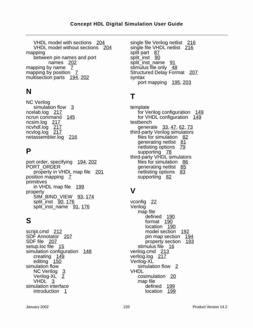
Concept HDL Digital Simulation User Guide
VHDL model with sections 204VHDL model without sections 204
mappingbetween pin names and port
names 202mapping by name 7mapping by position 7multisection parts 194, 202
NNC Verilog
simulation flow 3ncelab.log 217ncrun command 145ncsim.log 217ncvhdl.log 217ncvlog.log 217netassembler.log 216
Pport order, specifying 194, 202PORT_ORDER
property in VHDL map file 201position mapping 7primitives
in VHDL map file 199property
SIM_BIND_VIEW 93, 174split_inst 90, 176split_inst_name 91, 176
Sscript.cmd 212SDF Annotator 207SDF file 207setup.loc file 15simulation configuration 148
creating 149editing 150
simulation flowNC Verilog 3Verilog-XL 2VHDL 3
simulation interfaceintroduction 1
single file Verilog netlist 216single file VHDL netlist 216split part 87split_inst 90split_inst_name 91stimulus file only 48Structured Delay Format 207syntax
port mapping 195, 203
Ttemplate
for Verilog configuration 149for VHDL configuration 149
testbenchgenerate 33, 47, 62, 73
third-party Verilog simulatorsfiles for simulation 82generating netlist 81netlisting options 79supporting 78
third-party VHDL simulatorsfiles for simulation 86generating netlist 85netlisting options 83supporting 82
Vvconfig 22Verilog
map filedefined 190format 190location 190model section 192pin map section 194property section 193
stimulus file 16verilog.cmd 213verilog.log 217Verilog-XL
simulation flow 2VHDL
cosimulation 20map file
defined 199location 199
January 2002 220 Product Version 14.2

Concept HDL Digital Simulation User Guide
model section 200primitive section 200property section 201
modelspecifying actual name 201
pin map section 202simulation flow 3
vhdl_map fileformat 199location 199
vlog_model_path.txt file 14
January 2002 221 Product Version 14.2

Concept HDL Digital Simulation User Guide
January 2002 222 Product Version 14.2