concept-mapping software
TRANSCRIPT

Concept-Mapping Software

Trademark Notice
Copyright Notice
Acknowledgments
SMART Ideas is a registered trademark of SMART Technologies Inc. in Canada and the U.S. SMART Ideas and SMART Board are trademarks of SMART Technologies Inc. All SMART product logotypes and the SMART Ideas and SMART logos are trademarks of SMART Technologies Inc. All other third-party product and company names are mentioned for identification purposes only and may be trademarks of their respective owners.
U.S., Canadian and foreign patents pending.
© 1995–2005 SMART Technologies Inc. All rights reserved.
No part of this publication may be reproduced, transmitted, transcribed, stored in a retrieval system or translated into any language in any form by any means without the prior written consent of SMART. Information in this manual is subject to change without notice and does not represent a commitment on the part of SMART.
Printed in Canada 6/2005.
We gratefully acknowledge Special Collections, Cleveland State University Library for permission to reproduce the photograph of Richard Burton as Hamlet.
Some clip art supplied by CorelDRAW, a registered trademark of Corel Corporation.
Registration Benefits
At SMART, we’re always working to improve our customers’ experience by offering software upgrades, patches and product news. Register your copy of SMART Ideas software to receive announcements of upgrades and patches in the future.
Keep the following information available in case you need to contact Technical Support:
Register online at:
Serial Number
Date of Purchase
www.smarttech.com/products/registration

Table of Contents
Welcome to SMART Ideas Software........................................................1About Concept Maps ............................................................................................. 1About This Guide................................................................................................... 2
Creating a Diagram...................................................................................3Symbols................................................................................................................. 3Creating Symbols .................................................................................................. 4Rapidly Creating a Connected Diagram ................................................................ 5Linking Symbols with Connectors.......................................................................... 8Labeling Connectors............................................................................................ 11
Editing a Diagram ...................................................................................13Selecting Symbols and Connectors..................................................................... 13Moving Diagram Objects ..................................................................................... 14Changing Diagram Layout................................................................................... 16Distributing Symbols............................................................................................ 20Resizing Symbols ................................................................................................ 21Deleting Objects .................................................................................................. 23Cutting, Copying and Pasting Objects................................................................. 24Protecting Objects from Editing ........................................................................... 24Undoing Changes................................................................................................ 25
Using Styles and Style Collections.......................................................27Styles: An Overview ............................................................................................ 27Formatting Symbols with Styles .......................................................................... 28Formatting Connectors with Styles...................................................................... 31About Style Collections........................................................................................ 34Creating a New Custom Style Collection............................................................. 35Adding Styles to Custom Style Collections.......................................................... 36Importing Online Style Collections....................................................................... 38Saving a Style Collection as a File ...................................................................... 39Style Names ........................................................................................................ 40
Customizing Your Diagram....................................................................43
Table of Contents
Changing Symbol Appearance............................................................................ 43Changing Connector Appearance ....................................................................... 44Adding Two-Color Patterns and Gradients to Symbol Fills ................................. 46Using StylePaint to Copy an Object’s Formatting................................................ 47Adding a Video File to a Symbol ......................................................................... 48Adding a Sound File to a Symbol ........................................................................ 51Adding a Note to a Symbol.................................................................................. 54Making a Symbol Transparent............................................................................. 56Adding a Shadow to a Symbol ............................................................................ 57Using an Imported Image as a Symbol ............................................................... 58Using Clip Art as a Symbol.................................................................................. 60Importing Images into the Clip Art Gallery........................................................... 61Using Interactive Cliplets ..................................................................................... 64Grouping Your Symbols with Sticky Symbols...................................................... 67Adding a Legend to Your Diagram ...................................................................... 70Inserting a Blank Legend..................................................................................... 71Converting a Legend to a Custom Style Collection ............................................. 73
Getting to Know the Workspace............................................................75Sub-Level Workspaces........................................................................................ 75Tools for Navigating in Your Sub-Level Workspaces .......................................... 76Viewing Sub-Levels ............................................................................................ 77Workspace Views ................................................................................................ 78Maximizing the Workspace.................................................................................. 80Using the Workspace Grid................................................................................... 81Changing the Background Color ......................................................................... 82Applying a Color Scheme to Your Diagram......................................................... 84Changing Skins ................................................................................................... 85Using the Zoom Feature...................................................................................... 86Moving Around the Workspace ........................................................................... 87Shrinking and Expanding Diagram Trees............................................................ 88
Working with Text ...................................................................................91Editing Text.......................................................................................................... 91Formatting Text ................................................................................................... 92Checking Your Spelling ....................................................................................... 92Finding and Replacing Text................................................................................. 94
Adding Layers and Links to Diagrams .................................................97
Table of Contents

Creating Layered Diagrams................................................................................. 97Showing Sub-Levels.......................................................................................... 100Navigating through Symbol Layers.................................................................... 101Creating Links to Websites, Files or Other Diagram Levels .............................. 101Removing and Replacing Links ......................................................................... 105
Working in Outline View.......................................................................107Understanding Outline View .............................................................................. 108Creating Topics ................................................................................................. 109Creating Notes, Links and Sub-levels ............................................................... 111Editing Text in Outline View............................................................................... 112Reorganizing Your Outline ................................................................................ 112Hiding and Revealing Topics in Outline View.................................................... 113
File Management.................................................................................. 115Creating a New SMART Ideas File.................................................................... 115Opening a SMART Ideas File............................................................................ 116Saving a SMART Ideas File .............................................................................. 116Exporting a SMART Ideas File to Word, WordPerfect or AppleWorks .............. 117Printing a Diagram............................................................................................. 119Using Print Preview ........................................................................................... 120Using Templates in SMART Ideas Software ..................................................... 121
Using SMART Ideas Software on a SMART Board Interactive White-board......................................................................................................125Creating Symbols with a Pen Tray Pen............................................................. 126Editing with a Pen Tray pen .............................................................................. 129
Customer Support ................................................................................131
Appendix A: Using SMART Ideas Server Software ...........................133
Appendix B: Using SMART Ideas Software on a Tablet PC..............145
Appendix C: License Agreement.........................................................155
Index.......................................................................................................165
Table of Contents

Table of Contents
Welcome to SMART Ideas Software
Congratulations on purchasing SMART Ideas® software—the most versatile and powerful concept-mapping software available.
About Concept MapsA concept map lets you capture and display ideas and their relationships in a clear, graphical way, with an immediacy that’s just not possible with formal, linear text.
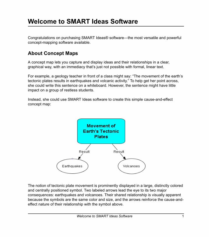
For example, a geology teacher in front of a class might say: “The movement of the earth’s tectonic plates results in earthquakes and volcanic activity.” To help get her point across, she could write this sentence on a whiteboard. However, the sentence might have little impact on a group of restless students.
Instead, she could use SMART Ideas software to create this simple cause-and-effect concept map:
The notion of tectonic plate movement is prominently displayed in a large, distinctly colored and centrally positioned symbol. Two labeled arrows lead the eye to its two major consequences: earthquakes and volcanoes. Their shared relationship is visually apparent because the symbols are the same color and size, and the arrows reinforce the cause-and-effect nature of their relationship with the symbol above.
Welcome to SMART Ideas Software 1

The effectiveness of this concept map visually reinforces her spoken words, but its effectiveness goes well beyond that of a simple visual aid. By liberating ideas from the limitations of syntax, concept maps can deepen students’ understanding and provoke genuine interest. With SMART Ideas software, it’s up to you: You can make your concept maps simple and austere to show the basic connections between ideas or you can make them as elaborate and eye-catching as you like.
About This GuideIn SMART Ideas software, we use the term “diagram” for concept map. Throughout this guide, we’ll refer to the concept maps you create with SMART Ideas software as diagrams.
First, you’ll learn how to create and edit simple diagrams with SMART Ideas software. Then you’ll go beyond the basics to learn about the this program’s many advanced features, like importing clip art and other graphics, using the Outline view, adding hyperlinks, and creating diagrams with multiple levels.
2 Welcome to SMART Ideas Software
Creating a Diagram
The SMART Ideas workspace is designed for quick, easy and flexible diagram creation. A diagram is made up of two components: symbols and connectors.
SymbolsIn SMART Ideas software, a symbol is a graphical object, such as a circle, a square or a picture, that encloses a text message. This message can be just a few words or a phrase. However, the more concise the message, the better.
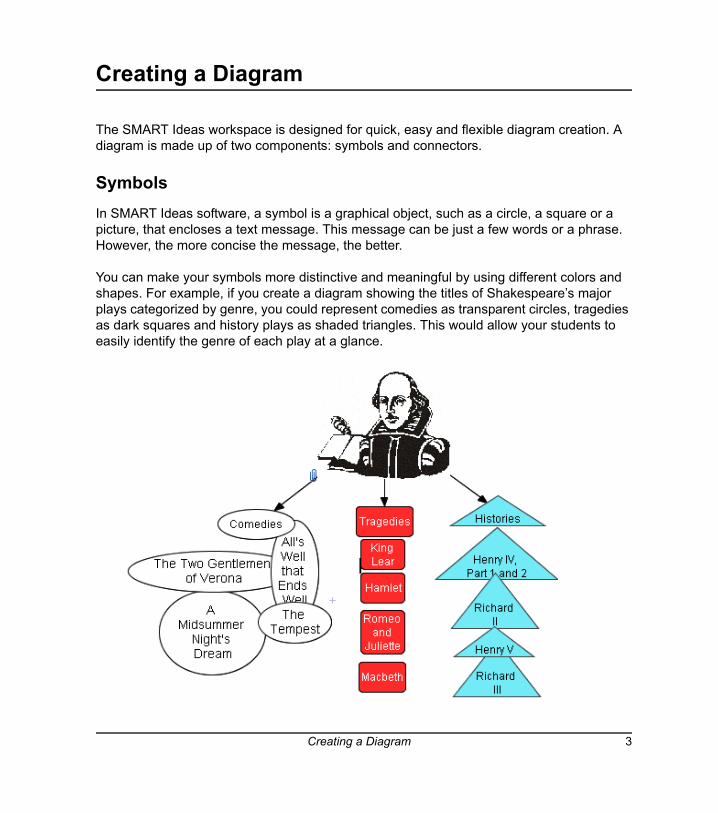
You can make your symbols more distinctive and meaningful by using different colors and shapes. For example, if you create a diagram showing the titles of Shakespeare’s major plays categorized by genre, you could represent comedies as transparent circles, tragedies as dark squares and history plays as shaded triangles. This would allow your students to easily identify the genre of each play at a glance.
Creating a Diagram 3
To enhance a symbol even further, try integrating an image with it. While SMART Ideas software comes with a handy clip art collection, you can use any collection of graphics or clip art as your image source.
For example, the image of Shakespeare in the diagram on the previous page adds historical context—and a point of departure for teaching. You could inform the class that this image is based on a portrait that appears on the cover of the first-folio edition of Shakespeare’s collected plays, printed in 1623, not long after his death. You could then talk about the significance of this publication, and even add an Internet ink to a site that’s devoted to an electronic version of the first folio edition. Just by adding one image, you’ve transformed your diagram into an effective learning resource.
Clearly, you can make a symbol as simple or as elaborate as you like. In this section, we’ll focus on how to create diagrams using simple symbols. In a later section, you’ll learn how to create diagrams using much more elaborate symbols.
Creating Symbols After you start SMART Ideas software, click the Open button and a new, untitled workspace appears, ready for your input.
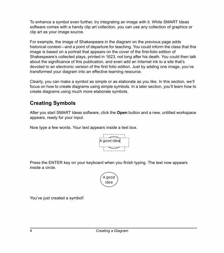
Now type a few words. Your text appears inside a text box.
Press the ENTER key on your keyboard when you finish typing. The text now appears inside a circle.
You’ve just created a symbol!
4 Creating a Diagram
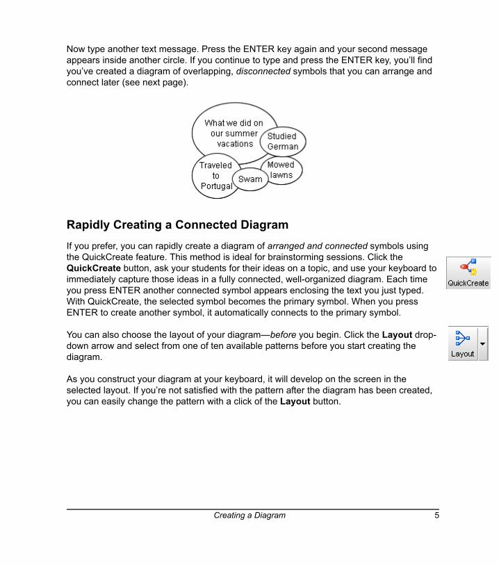
Now type another text message. Press the ENTER key again and your second message appears inside another circle. If you continue to type and press the ENTER key, you’ll find you’ve created a diagram of overlapping, disconnected symbols that you can arrange and connect later (see next page).
Rapidly Creating a Connected Diagram If you prefer, you can rapidly create a diagram of arranged and connected symbols using the QuickCreate feature. This method is ideal for brainstorming sessions. Click the QuickCreate button, ask your students for their ideas on a topic, and use your keyboard to immediately capture those ideas in a fully connected, well-organized diagram. Each time you press ENTER another connected symbol appears enclosing the text you just typed. With QuickCreate, the selected symbol becomes the primary symbol. When you press ENTER to create another symbol, it automatically connects to the primary symbol.
You can also choose the layout of your diagram—before you begin. Click the Layout drop-down arrow and select from one of ten available patterns before you start creating the diagram.
As you construct your diagram at your keyboard, it will develop on the screen in the selected layout. If you’re not satisfied with the pattern after the diagram has been created, you can easily change the pattern with a click of the Layout button.
Creating a Diagram 5
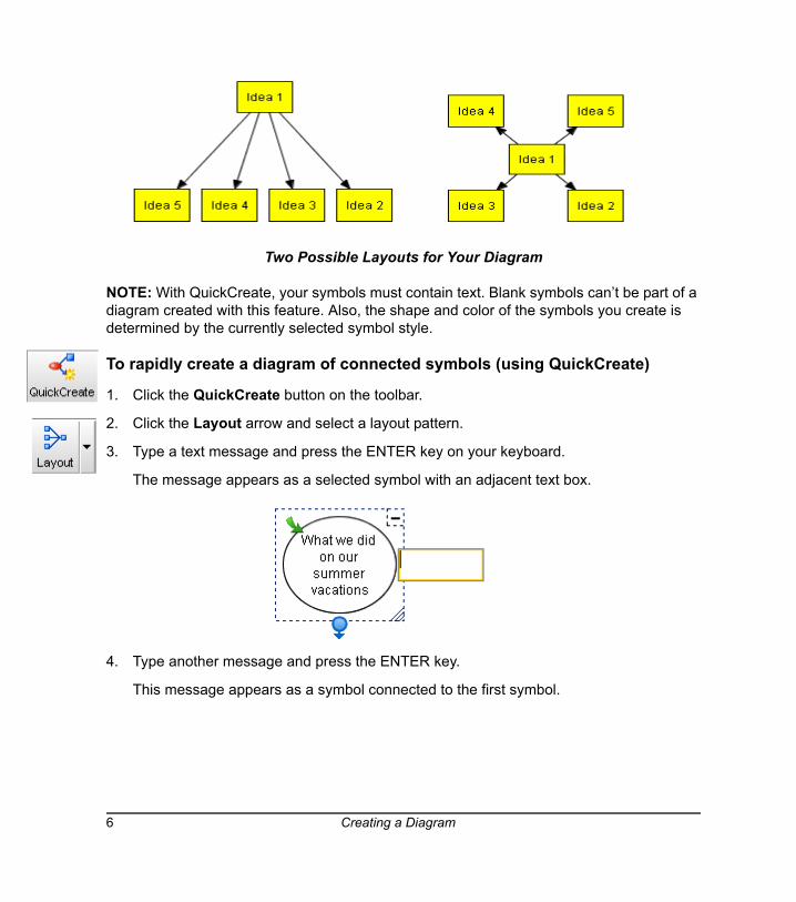
Two Possible Layouts for Your Diagram
NOTE: With QuickCreate, your symbols must contain text. Blank symbols can’t be part of a diagram created with this feature. Also, the shape and color of the symbols you create is determined by the currently selected symbol style.
To rapidly create a diagram of connected symbols (using QuickCreate)
1. Click the QuickCreate button on the toolbar.
2. Click the Layout arrow and select a layout pattern.
3. Type a text message and press the ENTER key on your keyboard.
The message appears as a selected symbol with an adjacent text box.
4. Type another message and press the ENTER key.
This message appears as a symbol connected to the first symbol.
6 Creating a Diagram
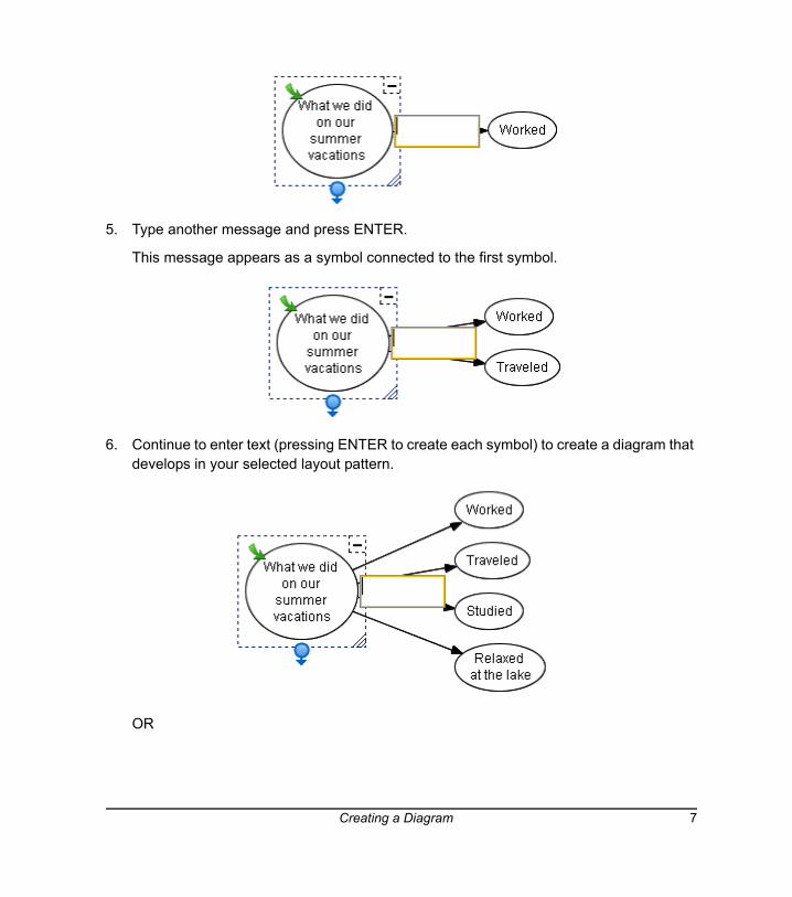
5. Type another message and press ENTER.
This message appears as a symbol connected to the first symbol.
6. Continue to enter text (pressing ENTER to create each symbol) to create a diagram that develops in your selected layout pattern.
OR
Creating a Diagram 7
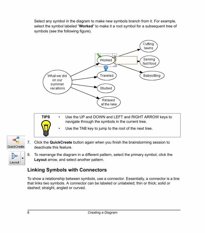
Select any symbol in the diagram to make new symbols branch from it. For example, select the symbol labeled “Worked” to make it a root symbol for a subsequent tree of symbols (see the following figure).
7. Click the QuickCreate button again when you finish the brainstorming session to deactivate this feature.
8. To rearrange the diagram in a different pattern, select the primary symbol, click the Layout arrow, and select another pattern.
Linking Symbols with ConnectorsTo show a relationship between symbols, use a connector. Essentially, a connector is a line that links two symbols. A connector can be labeled or unlabeled; thin or thick; solid or dashed; straight, angled or curved.
TIPS • Use the UP and DOWN and LEFT and RIGHT ARROW keys to navigate through the symbols in the current tree.
• Use the TAB key to jump to the root of the next tree.
8 Creating a Diagram
Connectors are also dynamic components of your SMART Ideas diagram: When you move a symbol that’s connected to another symbol, the connector moves with it. However, if the relationships between symbols change, you can move the connectors independently of their associated symbols.
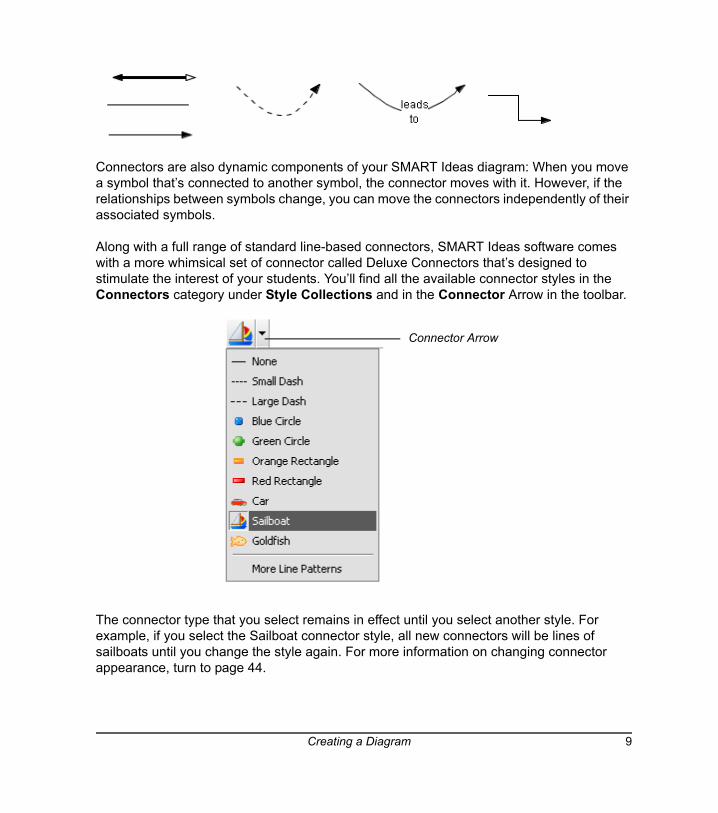
Along with a full range of standard line-based connectors, SMART Ideas software comes with a more whimsical set of connector called Deluxe Connectors that’s designed to stimulate the interest of your students. You’ll find all the available connector styles in the Connectors category under Style Collections and in the Connector Arrow in the toolbar.
The connector type that you select remains in effect until you select another style. For example, if you select the Sailboat connector style, all new connectors will be lines of sailboats until you change the style again. For more information on changing connector appearance, turn to page 44.
Connector Arrow
Creating a Diagram 9
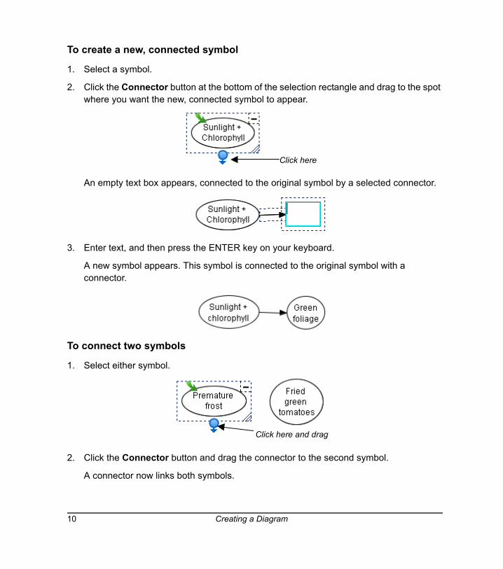
To create a new, connected symbol
1. Select a symbol.
2. Click the Connector button at the bottom of the selection rectangle and drag to the spot where you want the new, connected symbol to appear.
An empty text box appears, connected to the original symbol by a selected connector.
3. Enter text, and then press the ENTER key on your keyboard.
A new symbol appears. This symbol is connected to the original symbol with a connector.
To connect two symbols
1. Select either symbol.
2. Click the Connector button and drag the connector to the second symbol.
A connector now links both symbols.
Click here
Click here and drag
10 Creating a Diagram
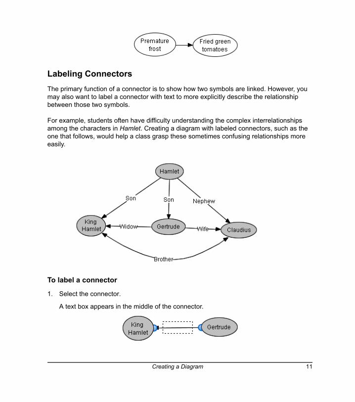
Labeling ConnectorsThe primary function of a connector is to show how two symbols are linked. However, you may also want to label a connector with text to more explicitly describe the relationship between those two symbols.
For example, students often have difficulty understanding the complex interrelationships among the characters in Hamlet. Creating a diagram with labeled connectors, such as the one that follows, would help a class grasp these sometimes confusing relationships more easily.
To label a connector
1. Select the connector.
A text box appears in the middle of the connector.
Creating a Diagram 11
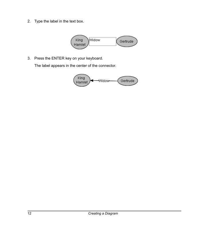
2. Type the label in the text box.
3. Press the ENTER key on your keyboard.
The label appears in the center of the connector.
12 Creating a Diagram
Editing a Diagram
This section will focus on how to:
• select objects for editing (page 13)
• move objects (page 14)
• rearrange diagrams (page 16)
• align objects (page 18)
• resize objects (page 21)
• delete objects (page 24)
• cut, copy and paste objects (page 24)
• protect objects from editing (page 25)
Selecting Symbols and ConnectorsTo work with a symbol or connector, you must first select it. If you like, you can change several symbols or connectors simultaneously by selecting them at the same time. To select all objects in the current workspace, click Select All on the Edit menu.
To select a symbol or connector
1. Move the cursor over the object you want to select.
2. Click once.
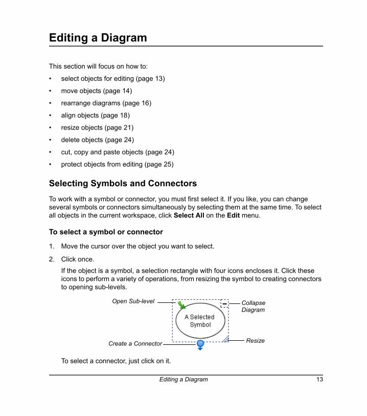
If the object is a symbol, a selection rectangle with four icons encloses it. Click these icons to perform a variety of operations, from resizing the symbol to creating connectors to opening sub-levels.
To select a connector, just click on it.
Open Sub-level CollapseDiagram
ResizeCreate a Connector
Editing a Diagram 13
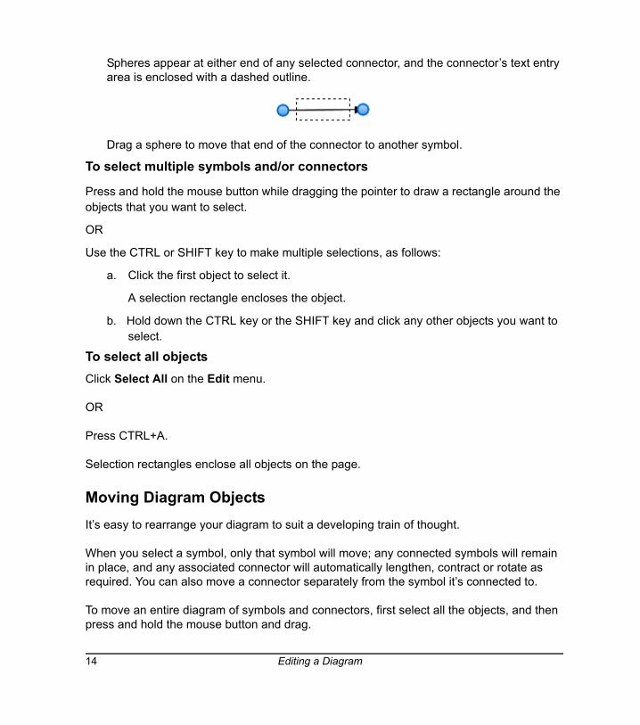
Spheres appear at either end of any selected connector, and the connector’s text entry area is enclosed with a dashed outline.
Drag a sphere to move that end of the connector to another symbol.
To select multiple symbols and/or connectors
Press and hold the mouse button while dragging the pointer to draw a rectangle around the objects that you want to select.
OR
Use the CTRL or SHIFT key to make multiple selections, as follows:
a. Click the first object to select it.
A selection rectangle encloses the object.
b. Hold down the CTRL key or the SHIFT key and click any other objects you want to select.
To select all objectsClick Select All on the Edit menu.
OR
Press CTRL+A.
Selection rectangles enclose all objects on the page.
Moving Diagram ObjectsIt’s easy to rearrange your diagram to suit a developing train of thought.
When you select a symbol, only that symbol will move; any connected symbols will remain in place, and any associated connector will automatically lengthen, contract or rotate as required. You can also move a connector separately from the symbol it’s connected to.
To move an entire diagram of symbols and connectors, first select all the objects, and then press and hold the mouse button and drag.
14 Editing a Diagram
If your diagram contains curved connectors, not only can you move them—you can reshape them to accommodate altered symbol configurations.
To move a symbol1. Click on the symbol.
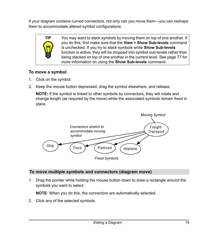
2. Keep the mouse button depressed, drag the symbol elsewhere, and release.
NOTE: If the symbol is linked to other symbols by connectors, they will rotate and change length (as required by the move) while the associated symbols remain fixed in place.
1. Drag the pointer while holding the mouse button down to draw a rectangle around the symbols you want to select.
NOTE: When you do this, the connectors are automatically selected.
2. Click any of the selected symbols.
TIP You may want to stack symbols by moving them on top of one another. If you do this, first make sure that the View > Show Sub-levels command is unchecked. If you try to stack symbols while Show Sub-levels function is active, they will be dropped into symbol sub-levels rather than being stacked on top of one another in the current level. See page 77 for more information on using the Show Sub-levels command.
To move multiple symbols and connectors (diagram move)
Moving Symbol
Fixed Symbols
Connectors stretch to accommodate moving symbol
Editing a Diagram 15
3. Hold down the mouse button and drag the objects to their new position.
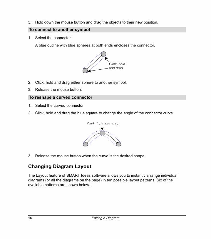
1. Select the connector.
A blue outline with blue spheres at both ends encloses the connector.
2. Click, hold and drag either sphere to another symbol.
3. Release the mouse button.
1. Select the curved connector.
2. Click, hold and drag the blue square to change the angle of the connector curve.
3. Release the mouse button when the curve is the desired shape.
Changing Diagram LayoutThe Layout feature of SMART Ideas software allows you to instantly arrange individual diagrams (or all the diagrams on the page) in ten possible layout patterns. Six of the available patterns are shown below.
To connect to another symbol
To reshape a curved connector
Click, holdand drag
C lic k , h o ld an d d ra g
16 Editing a Diagram
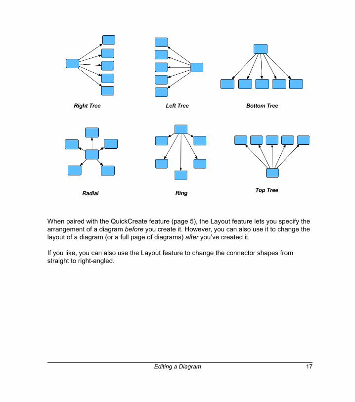
When paired with the QuickCreate feature (page 5), the Layout feature lets you specify the arrangement of a diagram before you create it. However, you can also use it to change the layout of a diagram (or a full page of diagrams) after you’ve created it.
If you like, you can also use the Layout feature to change the connector shapes from straight to right-angled.
Right Tree Left Tree Bottom Tree
Top TreeRadial Ring
Editing a Diagram 17
NOTE: If you apply a layout to an entire page, all your diagrams are centered on the page.
To change the layout of an existing diagram(s)
1. Select one or more diagrams.
2. Click the Layout arrow.
3. Click one of the ten layout buttons to select a layout.
SMART Ideas software modifies the layout of all selected diagrams.
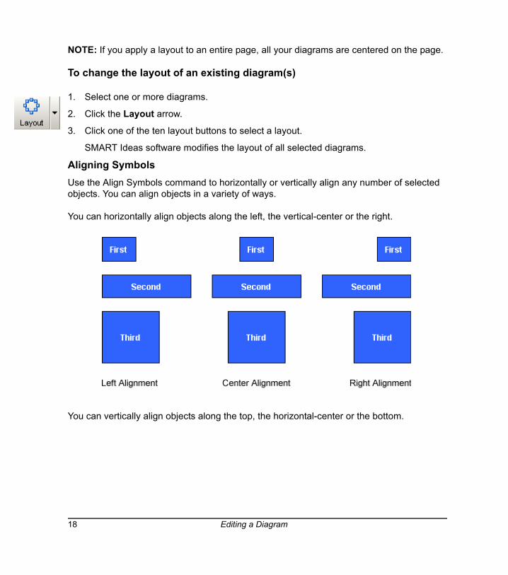
Aligning Symbols Use the Align Symbols command to horizontally or vertically align any number of selected objects. You can align objects in a variety of ways.
You can horizontally align objects along the left, the vertical-center or the right.
You can vertically align objects along the top, the horizontal-center or the bottom.
18 Editing a Diagram
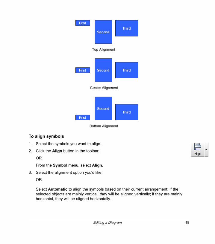
To align symbols1. Select the symbols you want to align.
2. Click the Align button in the toolbar.
OR
From the Symbol menu, select Align.
3. Select the alignment option you'd like.
OR
Select Automatic to align the symbols based on their current arrangement: If the selected objects are mainly vertical, they will be aligned vertically; if they are mainly horizontal, they will be aligned horizontally.
Editing a Diagram 19
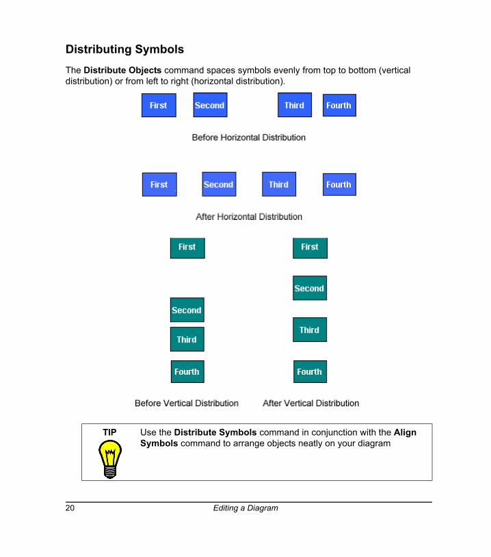
Distributing SymbolsThe Distribute Objects command spaces symbols evenly from top to bottom (vertical distribution) or from left to right (horizontal distribution).
TIP Use the Distribute Symbols command in conjunction with the Align Symbols command to arrange objects neatly on your diagram
20 Editing a Diagram
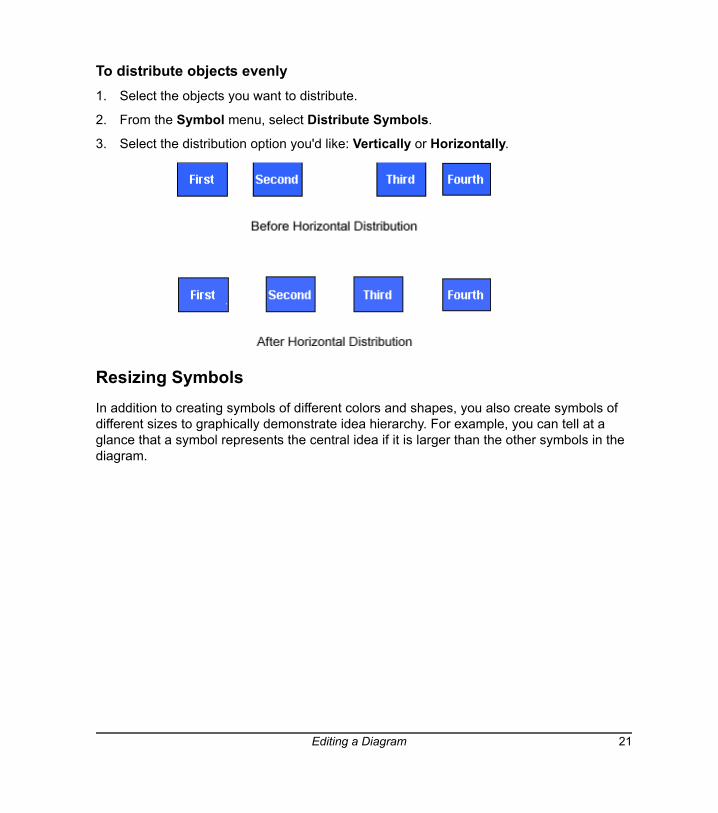
To distribute objects evenly1. Select the objects you want to distribute.
2. From the Symbol menu, select Distribute Symbols.
3. Select the distribution option you'd like: Vertically or Horizontally.
Resizing SymbolsIn addition to creating symbols of different colors and shapes, you also create symbols of different sizes to graphically demonstrate idea hierarchy. For example, you can tell at a glance that a symbol represents the central idea if it is larger than the other symbols in the diagram.
Editing a Diagram 21
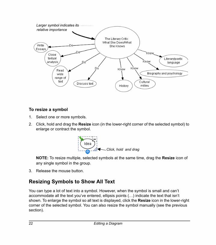
To resize a symbol 1. Select one or more symbols.
2. Click, hold and drag the Resize icon (in the lower-right corner of the selected symbol) to enlarge or contract the symbol.
NOTE: To resize multiple, selected symbols at the same time, drag the Resize icon of any single symbol in the group.
3. Release the mouse button.
Resizing Symbols to Show All Text You can type a lot of text into a symbol. However, when the symbol is small and can’t accommodate all the text you’ve entered, ellipsis points (…) indicate the text that isn’t shown. To enlarge the symbol so all text is displayed, click the Resize icon in the lower-right corner of the selected symbol. You can also resize the symbol manually (see the previous section).
Larger symbol indicates its relative importance
Click, hold and drag
22 Editing a Diagram
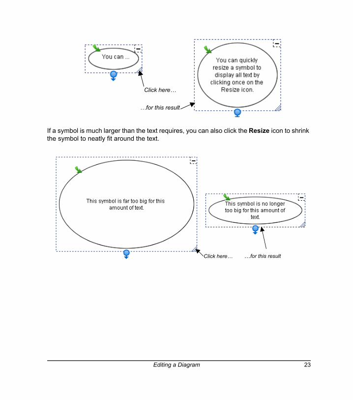
If a symbol is much larger than the text requires, you can also click the Resize icon to shrink the symbol to neatly fit around the text.
Click here…
…for this result
Click here… …for this result
Editing a Diagram 23
Deleting ObjectsDeleting an object may have an impact beyond the simple disappearance of the object.
• If a symbol has one or more sub-levels, those sub-levels (and all the objects on them) are also deleted.
• If a symbol has a hyperlink associated with it—for example, if it links to a file or website—that link is lost when you delete the symbol.
Deleting a connector, however, affects only that connector. The symbols on either side will remain intact.
To delete an object1. Select one or more objects.
2. Click the Delete button on the toolbar.
The selected object(s) disappears.
Cutting, Copying and Pasting ObjectsUse the Cut, Copy and Paste functions to duplicate or move any object in your current workspace to another diagram, sub-level or application through the Microsoft Windows clipboard.
To cut/copy and paste an object
1. Select one or more objects.
2. Click the Cut or Copy button on the toolbar.
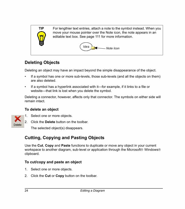
TIP For lengthier text entries, attach a note to the symbol instead. When you move your mouse pointer over the Note icon, the note appears in an editable text box. See page 111 for more information.
Note Icon
24 Editing a Diagram
OR
Select Cut or Copy from the Edit menu.
NOTE: If you’re copying a symbol with an associated sub-level, you’ll be asked if you want to copy the sub-level in addition to the symbol itself. Click the Yes button to copy the sub-level.
3. Click the Paste button in the toolbar.
OR
Select Paste from the Edit menu.
The object appears at the cursor insertion point.
Protecting Objects from EditingYou can protect an object or an entire group of objects from editing with the Make Background command. This command moves selected objects into the virtual background, out of reach of the selection tool.
NOTE: To restore all protected objects to the foreground for editing, select Retrieve Background from the Tools menu.
To protect an object from editing
1. Select the objects that you want to send to the background.
2. Select Make Background from the Tools menu.
The object or objects that you selected are now part of the background (and are no longer selectable).
Undoing ChangesIf you make a mistake (or simply change your mind), click the Undo button to reverse the previous command or action.
You can undo many previous actions by selecting Undo repeatedly. Once you've undone a previously issued command or object, you can also change your mind again and reinstate the original object (or edit) by selecting Redo from the Edit menu.
Editing a Diagram 25

To undo the effect of the last command or action
Click the Undo button in the toolbar.
OR
Select Undo from the Edit menu.
To redo the previous command revoked with Undo
Select Redo from the Edit menu.
26 Editing a Diagram
Using Styles and Style Collections
This section tells you about:
• Styles (this page)
• Formatting symbols with styles (page 28)
• Formatting connectors with styles (page 31)
• Style Collections (page 34)
• Creating a new custom Style Collection (page 35)
• Adding styles to custom Style Collections (page 36)
• Importing Style Collections (page 38)
• Saving a Style Collection as an .IPS file (page 39)
Styles: An OverviewSuppose you’ve spent a few minutes changing the appearance of a symbol (or a connector) to look exactly the way you want.
You’ve changed the fill color of the symbol to just the right shade of turquoise, added a unique color outline, chosen a distinctive shape, and made it 50% transparent. You may now want several other symbols to look exactly the same.
You could select those symbols and format each one in the same way, but that takes time, and it can be difficult to duplicate subtle shades of color with precision. Also, if you decide to change a small aspect of one symbol, you must repeat the same formatting tasks for each of them. Instead, you can save the original formatting in the form of a symbol style. Then apply the style to other symbols you want to share the same appearance.
Basically, a style is just a collection of characteristics that you can apply to any symbol in the workspace. A wide array of styles comes with SMART Ideas (see About Style Collections on page 34), but you can also create collections of your own customized styles. The new styles you create are made available each time you start up SMART Ideas software.
Using Styles and Style Collections 27
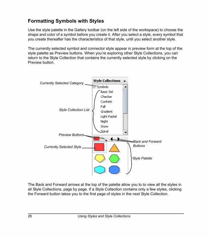
Formatting Symbols with StylesUse the style palette in the Gallery toolbar (on the left side of the workspace) to choose the shape and color of a symbol before you create it. After you select a style, every symbol that you create thereafter has the characteristics of that style, until you select another style.
The currently selected symbol and connector style appear in preview form at the top of the style palette as Preview buttons. When you’re exploring other Style Collections, you can return to the Style Collection that contains the currently selected style by clicking on the Preview button.
The Back and Forward arrows at the top of the palette allow you to to view all the styles in all Style Collections, page by page. If a Style Collection contains only a few styles, clicking the Forward button takes you to the first page of styles in the next Style Collection.
Currently Selected Style
Preview Buttons
Back and Forward Buttons
Currently Selected Category
Style Collection List
Style Palette
28 Using Styles and Style Collections
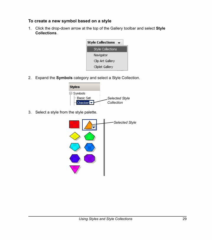
To create a new symbol based on a style1. Click the drop-down arrow at the top of the Gallery toolbar and select Style
Collections.
2. Expand the Symbols category and select a Style Collection.
3. Select a style from the style palette.
Selected Style Collection
Selected Style
Using Styles and Style Collections 29
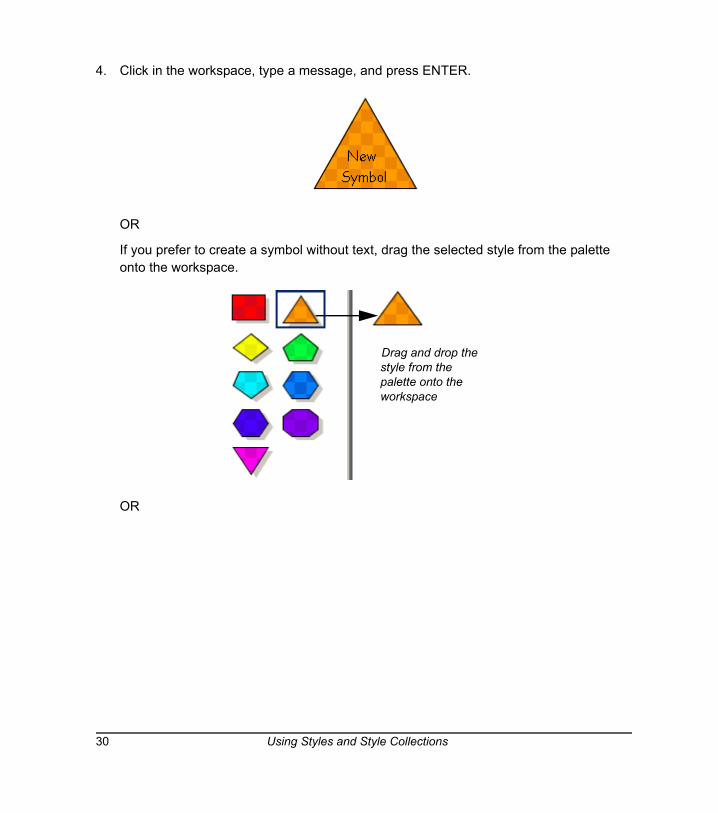
4. Click in the workspace, type a message, and press ENTER.
OR
If you prefer to create a symbol without text, drag the selected style from the palette onto the workspace.
OR
Drag and drop the style from the palette onto the workspace
30 Using Styles and Style Collections
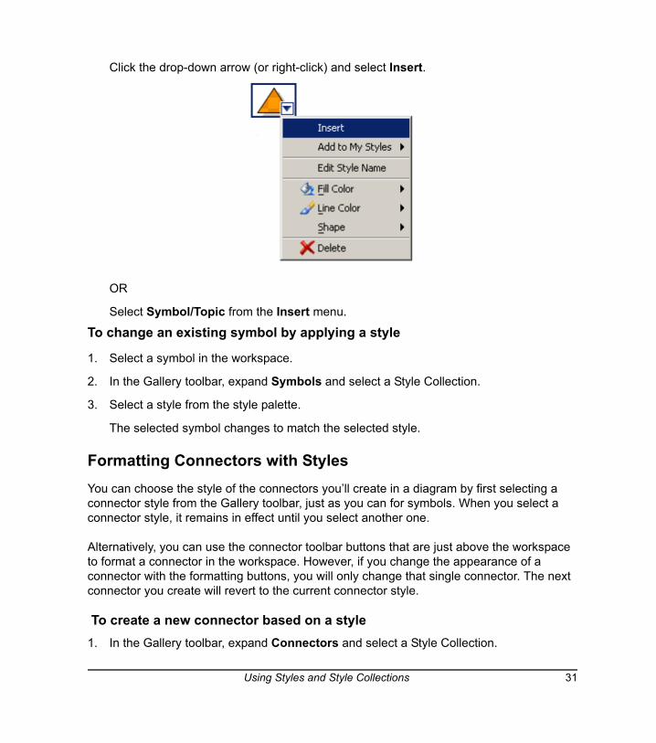
Click the drop-down arrow (or right-click) and select Insert.
OR
Select Symbol/Topic from the Insert menu.
To change an existing symbol by applying a style
1. Select a symbol in the workspace.
2. In the Gallery toolbar, expand Symbols and select a Style Collection.
3. Select a style from the style palette.
The selected symbol changes to match the selected style.
Formatting Connectors with StylesYou can choose the style of the connectors you’ll create in a diagram by first selecting a connector style from the Gallery toolbar, just as you can for symbols. When you select a connector style, it remains in effect until you select another one.
Alternatively, you can use the connector toolbar buttons that are just above the workspace to format a connector in the workspace. However, if you change the appearance of a connector with the formatting buttons, you will only change that single connector. The next connector you create will revert to the current connector style.
To create a new connector based on a style1. In the Gallery toolbar, expand Connectors and select a Style Collection.
Using Styles and Style Collections 31
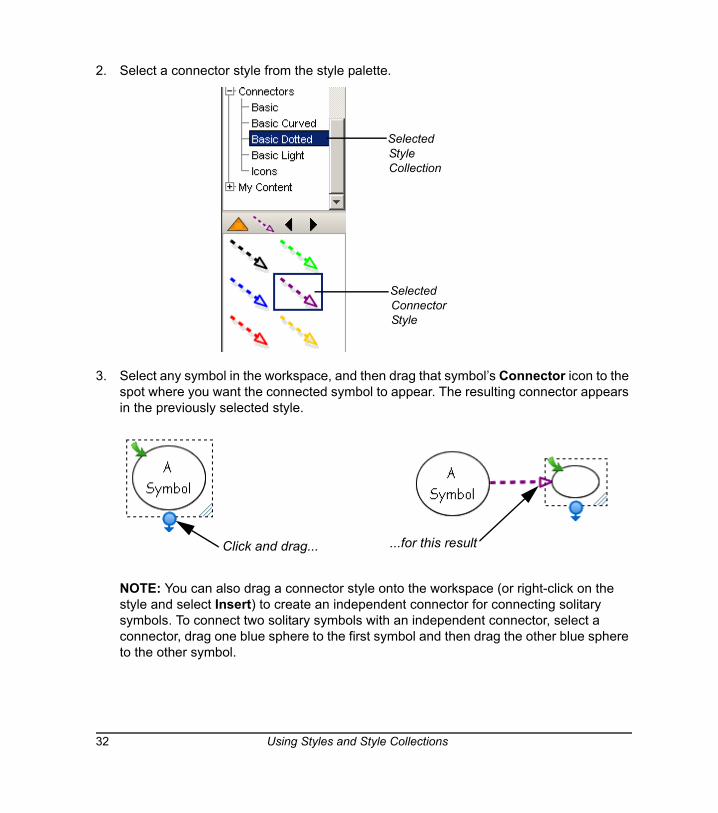
2. Select a connector style from the style palette.
3. Select any symbol in the workspace, and then drag that symbol’s Connector icon to the spot where you want the connected symbol to appear. The resulting connector appears in the previously selected style.
NOTE: You can also drag a connector style onto the workspace (or right-click on the style and select Insert) to create an independent connector for connecting solitary symbols. To connect two solitary symbols with an independent connector, select a connector, drag one blue sphere to the first symbol and then drag the other blue sphere to the other symbol.
Selected Connector Style
Selected Style Collection
Click and drag... ...for this result
32 Using Styles and Style Collections
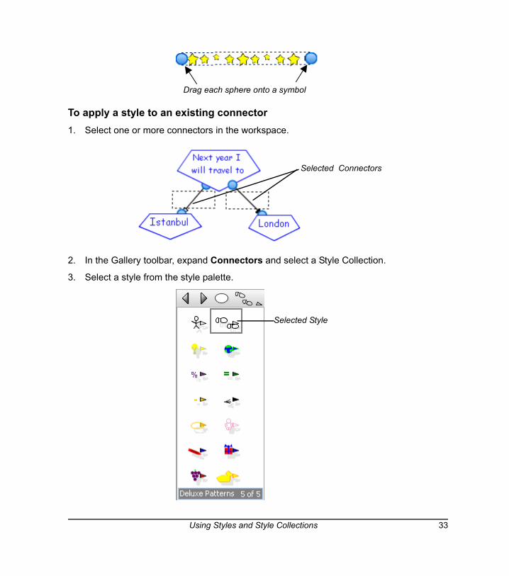
To apply a style to an existing connector 1. Select one or more connectors in the workspace.
2. In the Gallery toolbar, expand Connectors and select a Style Collection.
3. Select a style from the style palette.
Drag each sphere onto a symbol
Selected Connectors
Selected Style
Using Styles and Style Collections 33
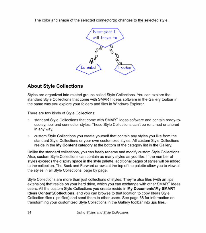
The color and shape of the selected connector(s) changes to the selected style.
About Style CollectionsStyles are organized into related groups called Style Collections. You can explore the standard Style Collections that come with SMART Ideas software in the Gallery toolbar in the same way you explore your folders and files in Windows Explorer.
There are two kinds of Style Collections:
• standard Style Collections that come with SMART Ideas software and contain ready-to-use symbol and connector styles. These Style Collections can’t be renamed or altered in any way.
• custom Style Collections you create yourself that contain any styles you like from the standard Style Collections or your own customized styles. All custom Style Collections reside in the My Content category at the bottom of the category list in the Gallery.
Unlike the standard collections, you can freely rename and modify custom Style Collections. Also, custom Style Collections can contain as many styles as you like. If the number of styles exceeds the display space in the style palette, additional pages of styles will be added to the collection. The Back and Forward arrows at the top of the palette allow you to view all the styles in all Style Collections, page by page.
Style Collections are more than just collections of styles: They’re also files (with an .ips extension) that reside on your hard drive, which you can exchange with other SMART Ideas users. All the custom Style Collections you create reside in My Documents\My SMART Ideas Content\Collections, and you can browse to that location to copy Ideas Style Collection files (.ips files) and send them to other users. See page 38 for information on transforming your customized Style Collections in the Gallery toolbar into .ips files.
34 Using Styles and Style Collections
Creating a New Custom Style CollectionWhile the styles available in the standard Style Collections may be sufficient for what you want to do, you can also create your own custom Style Collections, mixing and matching standard styles, or using them as starting points for creating unique styles.
Organize the styles in any way that is useful to you. All the standard Style Collections contain symbols or connectors that share similar visual characteristics.
When you create a custom Style Collection, you may prefer to organize the styles into functional groups that you’ve developed for a particular purpose. For example, you could group all the styles that you use for creating concept maps related to geology into a Style Collection called Geology, regardless of what they look like.
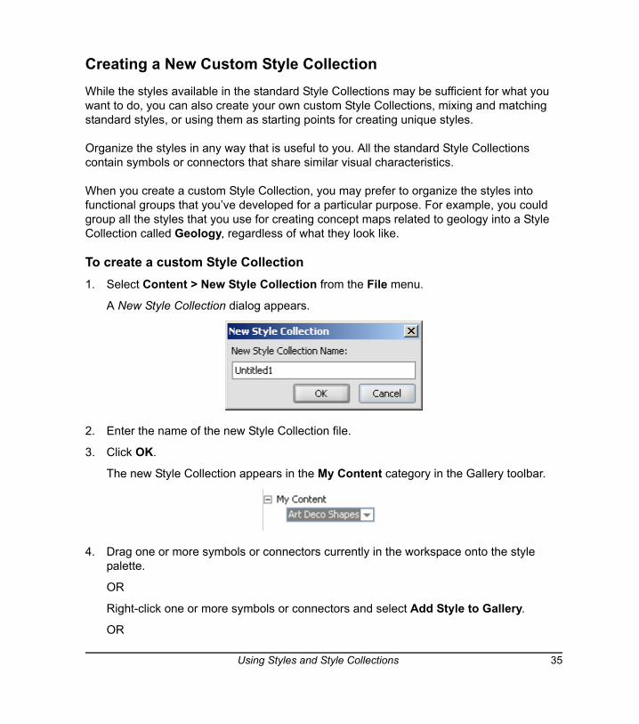
To create a custom Style Collection 1. Select Content > New Style Collection from the File menu.
A New Style Collection dialog appears.
2. Enter the name of the new Style Collection file.
3. Click OK.
The new Style Collection appears in the My Content category in the Gallery toolbar.
4. Drag one or more symbols or connectors currently in the workspace onto the style palette.
OR
Right-click one or more symbols or connectors and select Add Style to Gallery.
OR
Using Styles and Style Collections 35
Select one or more symbols or connectors and select Add Style to Gallery from the Tools menu.
NOTE: You may want to open other Style Collections to populate the workspace with the styles you want to add to your custom Style Collection. If you prefer, use styles from other collections as the starting point for creating unique styles (see Changing Symbol Appearance on page 43, and Changing Connector Appearance on page 44).
Adding Styles to Custom Style CollectionsYou can freely add styles or styles that are already in other collections to your custom Style Collections.
There are two ways to add styles:
• drag any symbol in the workspace directly onto the palette. The symbol can be one you’ve modified yourself (see Changing Symbol Appearance on page 43, and Changing Connector Appearance on page 44), or a symbol based on a style in another collection. You may first want to open another Style Collection to populate the workspace with the styles you want to add.
• import styles directly from other Style Collections (standard or custom)
A Favorites category is also available for those who prefer to quickly place all their favorite styles into one catch-all category.
To add a style to a custom Style Collection1. Select the custom Style Collection to which you want to add styles in the Gallery toolbar.
2. Click and drag one or more symbols or connectors currently in the workspace onto the style palette.
OR
Right-click one or more symbols or connectors and select Add Style to Gallery.
OR
Select one or more symbols or connectors and select Add Style to Gallery from the Tools menu.
36 Using Styles and Style Collections
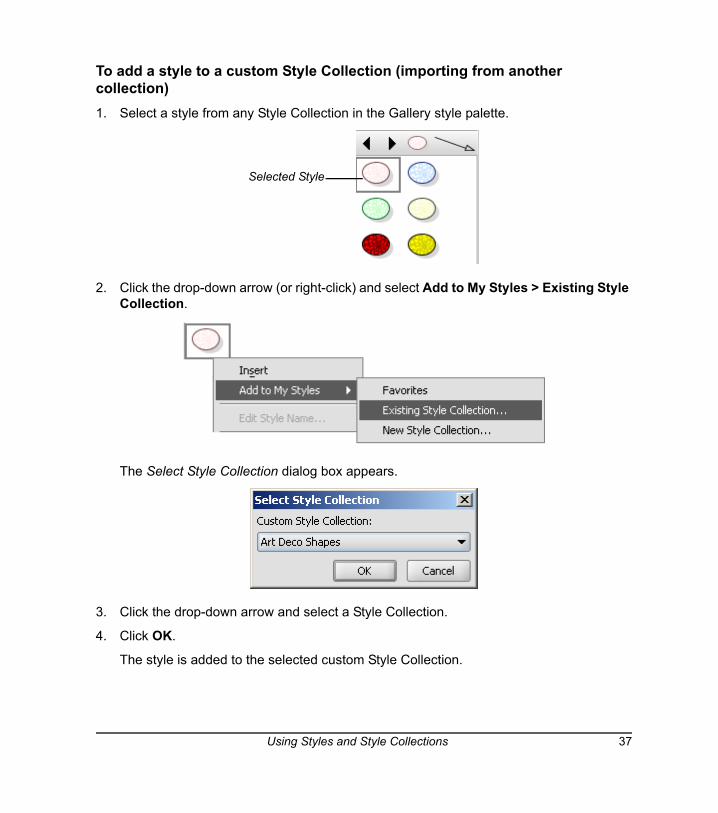
To add a style to a custom Style Collection (importing from another collection)1. Select a style from any Style Collection in the Gallery style palette.
2. Click the drop-down arrow (or right-click) and select Add to My Styles > Existing Style Collection.
The Select Style Collection dialog box appears.
3. Click the drop-down arrow and select a Style Collection.
4. Click OK.
The style is added to the selected custom Style Collection.
Selected Style
Using Styles and Style Collections 37

To add a style to the Favorites category1. Select a Style Collection in the Gallery toolbar.
2. Select a style from the style palette.
3. Click the drop-down arrow (or right-click) and select Add to My Styles > Favorites.
Importing Online Style CollectionsMany new Style Collections (and other SMART Ideas activities) are available at www.EDCompass.com, an online community for educators who use products from SMART Technologies. This website contains hundreds of resources and helpful hints, especially tailored for the unique needs of educators.
To import online Style CollectionsSelect Content > Import Online Content from the File menu.
The www.EDCompass.com website will open at the SMART Ideas Activities page. Follow the instructions to download new Style Collections from this site.
Converting an Ideas Style Collection (.IPS) File into a Style Collection in the GalleryIt’s easy to download new Ideas Style Collections (.ips) files from www.EDCompass.com (see the procedure above) or send them to and receive them from other users (see page 39).
After receiving a new .ips, your next task is to import it into the Gallery toolbar. Use the Open command to browse to and open the file. The .ips file will then appear as a Style Collection in the My Content category of the Gallery toolbar. The Style Collection reappears every time you start up SMART Ideas software, until you close the Style Collection. Closing a Style Collection removes it completely from the Gallery toolbar.
All the custom Style Collections you create reside in My Documents\My SMART Ideas Content\Collections, and you can browse to that location to copy SMART Ideas Style Collection files (.ips files) and send them to others.
NOTE: You can’t import new Style Collections into any of the standard Style Collections in the Symbols or Connectors categories. Neither can you close any of the standard Style Collections.
38 Using Styles and Style Collections
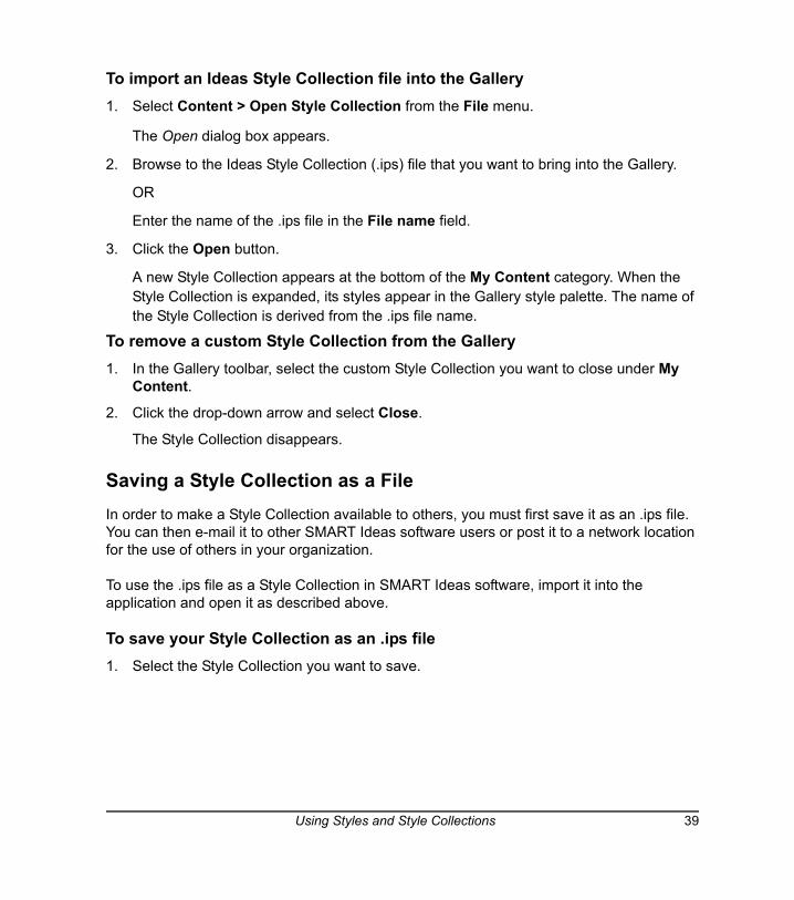
To import an Ideas Style Collection file into the Gallery1. Select Content > Open Style Collection from the File menu.
The Open dialog box appears.
2. Browse to the Ideas Style Collection (.ips) file that you want to bring into the Gallery.
OR
Enter the name of the .ips file in the File name field.
3. Click the Open button.
A new Style Collection appears at the bottom of the My Content category. When the Style Collection is expanded, its styles appear in the Gallery style palette. The name of the Style Collection is derived from the .ips file name.
To remove a custom Style Collection from the Gallery1. In the Gallery toolbar, select the custom Style Collection you want to close under My
Content.
2. Click the drop-down arrow and select Close.
The Style Collection disappears.
Saving a Style Collection as a FileIn order to make a Style Collection available to others, you must first save it as an .ips file. You can then e-mail it to other SMART Ideas software users or post it to a network location for the use of others in your organization.
To use the .ips file as a Style Collection in SMART Ideas software, import it into the application and open it as described above.
To save your Style Collection as an .ips file1. Select the Style Collection you want to save.
Using Styles and Style Collections 39
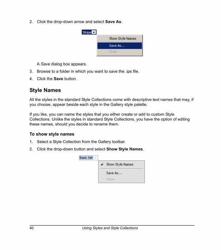
2. Click the drop-down arrow and select Save As.
A Save dialog box appears.
3. Browse to a folder in which you want to save the .ips file.
4. Click the Save button.
Style NamesAll the styles in the standard Style Collections come with descriptive text names that may, if you choose, appear beside each style in the Gallery style palette.
If you like, you can name the styles that you either create or add to custom Style Collections. Unlike the styles in standard Style Collections, you have the option of editing these names, should you decide to rename them.
To show style names1. Select a Style Collection from the Gallery toolbar.
2. Click the drop-down button and select Show Style Names.
40 Using Styles and Style Collections
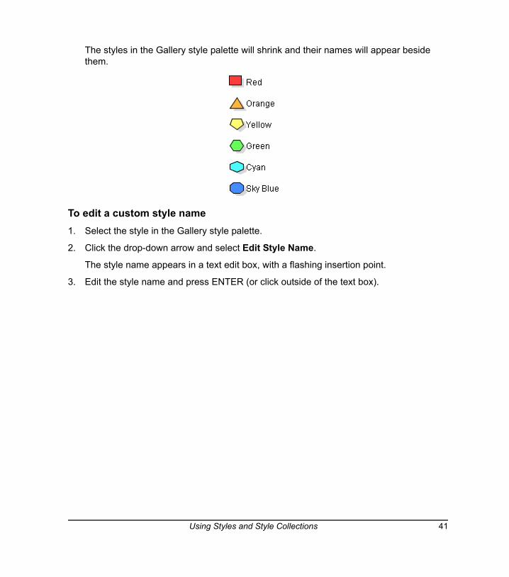
The styles in the Gallery style palette will shrink and their names will appear beside them.
To edit a custom style name1. Select the style in the Gallery style palette.
2. Click the drop-down arrow and select Edit Style Name.
The style name appears in a text edit box, with a flashing insertion point.
3. Edit the style name and press ENTER (or click outside of the text box).
Using Styles and Style Collections 41

42 Using Styles and Style Collections
Customizing Your Diagram
In this section, you’ll learn how to make your diagrams more distinctive by:
• customizing the color, line weight, transparency, shape, etc. of a symbol (this page)
• changing the appearance of connectors by selecting different line weights, colors, shapes and arrowheads (page 44)
• use StylePaint to transfer a selected object’s formatting to the next object you click on (page 47)
• adding a video file to a symbol (page 48)
• adding a sound file to a symbol (page 51)
• adding a note to a symbol (page 54)
• importing an image to use as a symbol (page 58)
• using clip art as a symbol (page 60)
• importing your own collections of clip art (page 61)
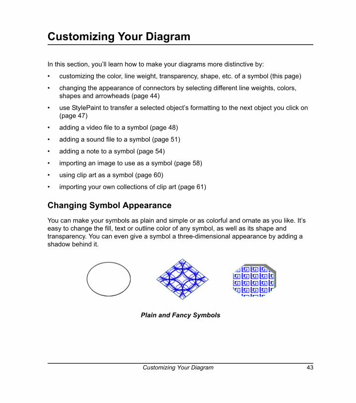
Changing Symbol AppearanceYou can make your symbols as plain and simple or as colorful and ornate as you like. It’s easy to change the fill, text or outline color of any symbol, as well as its shape and transparency. You can even give a symbol a three-dimensional appearance by adding a shadow behind it.
Plain and Fancy Symbols
Customizing Your Diagram 43
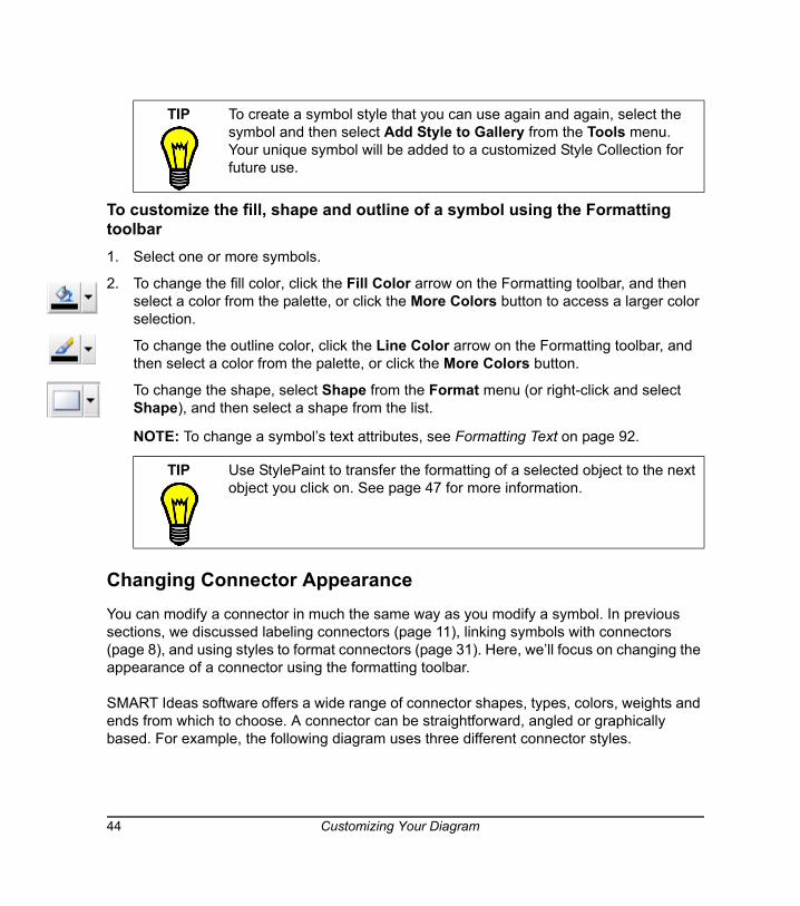
To customize the fill, shape and outline of a symbol using the Formatting toolbar1. Select one or more symbols.
2. To change the fill color, click the Fill Color arrow on the Formatting toolbar, and then select a color from the palette, or click the More Colors button to access a larger color selection.
To change the outline color, click the Line Color arrow on the Formatting toolbar, and then select a color from the palette, or click the More Colors button.
To change the shape, select Shape from the Format menu (or right-click and select Shape), and then select a shape from the list.
NOTE: To change a symbol’s text attributes, see Formatting Text on page 92.
Changing Connector AppearanceYou can modify a connector in much the same way as you modify a symbol. In previous sections, we discussed labeling connectors (page 11), linking symbols with connectors (page 8), and using styles to format connectors (page 31). Here, we’ll focus on changing the appearance of a connector using the formatting toolbar.
SMART Ideas software offers a wide range of connector shapes, types, colors, weights and ends from which to choose. A connector can be straightforward, angled or graphically based. For example, the following diagram uses three different connector styles.
TIP To create a symbol style that you can use again and again, select the symbol and then select Add Style to Gallery from the Tools menu. Your unique symbol will be added to a customized Style Collection for future use.
TIP Use StylePaint to transfer the formatting of a selected object to the next object you click on. See page 47 for more information.
44 Customizing Your Diagram
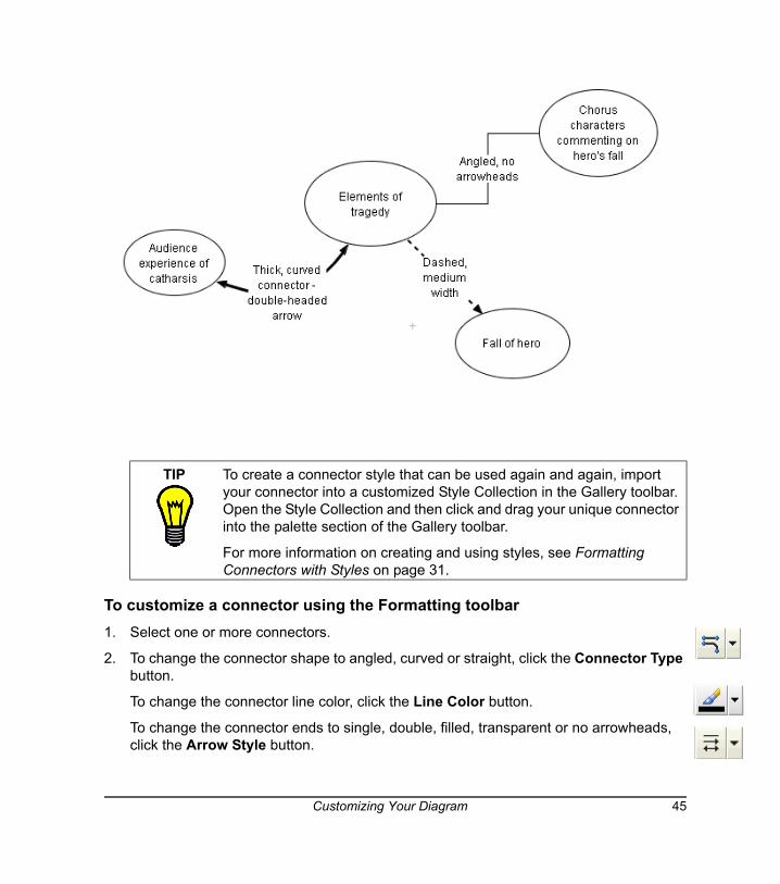
To customize a connector using the Formatting toolbar1. Select one or more connectors.
2. To change the connector shape to angled, curved or straight, click the Connector Type button.
To change the connector line color, click the Line Color button.
To change the connector ends to single, double, filled, transparent or no arrowheads, click the Arrow Style button.
TIP To create a connector style that can be used again and again, import your connector into a customized Style Collection in the Gallery toolbar. Open the Style Collection and then click and drag your unique connector into the palette section of the Gallery toolbar.
For more information on creating and using styles, see Formatting Connectors with Styles on page 31.
Customizing Your Diagram 45
To use an image-based connector, click the Deluxe Connector button.
To change the color of an image-based connector, click the Fill Color button.
NOTE: To customize connector labels, see Formatting Text on page 92.
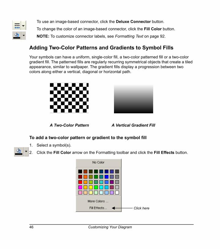
Adding Two-Color Patterns and Gradients to Symbol FillsYour symbols can have a uniform, single-color fill, a two-color patterned fill or a two-color gradient fill. The patterned fills are regularly recurring symmetrical objects that create a tiled appearance, similar to wallpaper. The gradient fills display a progression between two colors along either a vertical, diagonal or horizontal path.
A Two-Color Pattern A Vertical Gradient Fill
To add a two-color pattern or gradient to the symbol fill1. Select a symbol(s).
2. Click the Fill Color arrow on the Formatting toolbar and click the Fill Effects button.
Click here
46 Customizing Your Diagram
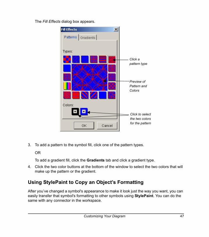
The Fill Effects dialog box appears.
3. To add a pattern to the symbol fill, click one of the pattern types.
OR
To add a gradient fill, click the Gradients tab and click a gradient type.
4. Click the two color buttons at the bottom of the window to select the two colors that will make up the pattern or the gradient.
Using StylePaint to Copy an Object’s FormattingAfter you’ve changed a symbol's appearance to make it look just the way you want, you can easily transfer that symbol's formatting to other symbols using StylePaint. You can do the same with any connector in the workspace.
Click apattern type
Preview ofPattern andColors
Click to selectthe two colorsfor the pattern
Customizing Your Diagram 47
To copy one object’s formatting to another object1. Select the object that has the formatting you want to copy to another object.
2. Click the StylePaint button.
3. The pointer turns into a paint brush.
Click the object to which you want to copy the original object’s formatting.
OR
Drag a selection area around several objects to apply the formatting to all of them at once.
4. When you finish copying the original object's formatting, click the StylePaint button again.
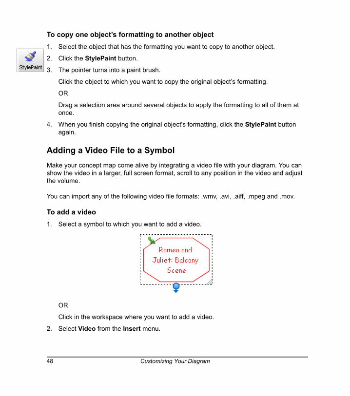
Adding a Video File to a SymbolMake your concept map come alive by integrating a video file with your diagram. You can show the video in a larger, full screen format, scroll to any position in the video and adjust the volume.
You can import any of the following video file formats: .wmv, .avi, .aiff, .mpeg and .mov.
To add a video 1. Select a symbol to which you want to add a video.
OR
Click in the workspace where you want to add a video.
2. Select Video from the Insert menu.
48 Customizing Your Diagram
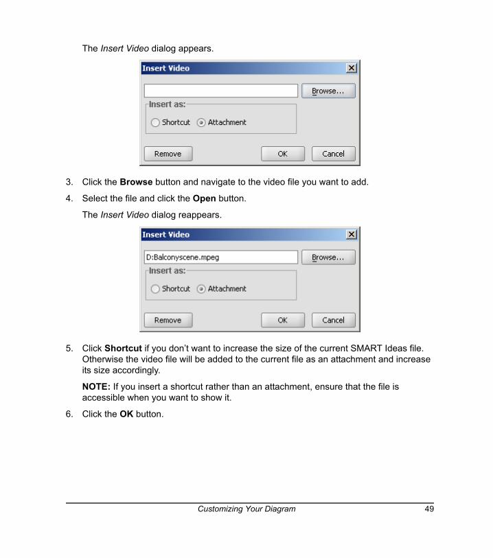
The Insert Video dialog appears.
3. Click the Browse button and navigate to the video file you want to add.
4. Select the file and click the Open button.
The Insert Video dialog reappears.
5. Click Shortcut if you don’t want to increase the size of the current SMART Ideas file. Otherwise the video file will be added to the current file as an attachment and increase its size accordingly.
NOTE: If you insert a shortcut rather than an attachment, ensure that the file is accessible when you want to show it.
6. Click the OK button.
Customizing Your Diagram 49
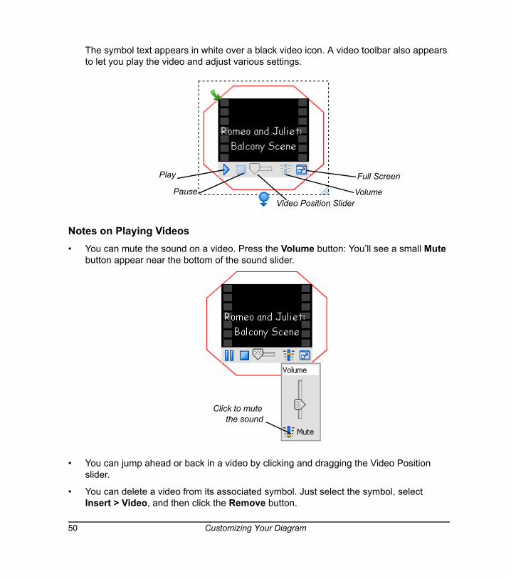
The symbol text appears in white over a black video icon. A video toolbar also appears to let you play the video and adjust various settings.
Notes on Playing Videos• You can mute the sound on a video. Press the Volume button: You’ll see a small Mute
button appear near the bottom of the sound slider.
• You can jump ahead or back in a video by clicking and dragging the Video Position slider.
• You can delete a video from its associated symbol. Just select the symbol, select Insert > Video, and then click the Remove button.
Play
Pause Volume
Full Screen
Video Position Slider
Click to mutethe sound
50 Customizing Your Diagram
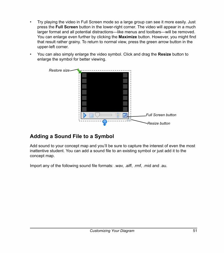
• Try playing the video in Full Screen mode so a large group can see it more easily. Just press the Full Screen button in the lower-right corner. The video will appear in a much larger format and all potential distractions—like menus and toolbars—will be removed. You can enlarge even further by clicking the Maximize button. However, you might find that result rather grainy. To return to normal view, press the green arrow button in the upper-left corner.
• You can also simply enlarge the video symbol. Click and drag the Resize button to enlarge the symbol for better viewing.
Adding a Sound File to a SymbolAdd sound to your concept map and you’ll be sure to capture the interest of even the most inattentive student. You can add a sound file to an existing symbol or just add it to the concept map.
Import any of the following sound file formats: .wav, .aiff, .rmf, .mid and .au.
Resize button
Full Screen button
Restore size
Customizing Your Diagram 51
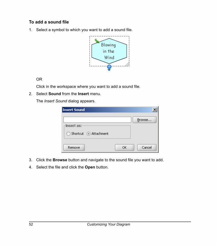
To add a sound file1. Select a symbol to which you want to add a sound file.
OR
Click in the workspace where you want to add a sound file.
2. Select Sound from the Insert menu.
The Insert Sound dialog appears.
3. Click the Browse button and navigate to the sound file you want to add.
4. Select the file and click the Open button.
52 Customizing Your Diagram
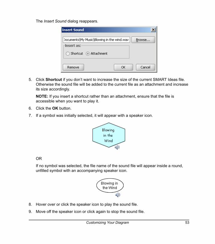
The Insert Sound dialog reappears.
5. Click Shortcut if you don’t want to increase the size of the current SMART Ideas file. Otherwise the sound file will be added to the current file as an attachment and increase its size accordingly.
NOTE: If you insert a shortcut rather than an attachment, ensure that the file is accessible when you want to play it.
6. Click the OK button.
7. If a symbol was initially selected, it will appear with a speaker icon.
OR
If no symbol was selected, the file name of the sound file will appear inside a round, unfilled symbol with an accompanying speaker icon.
8. Hover over or click the speaker icon to play the sound file.
9. Move off the speaker icon or click again to stop the sound file.
Customizing Your Diagram 53
NOTE: It’s easy to delete a sound file from its associated symbol. Just select the symbol, select Insert > Sound, and then click the Remove button.
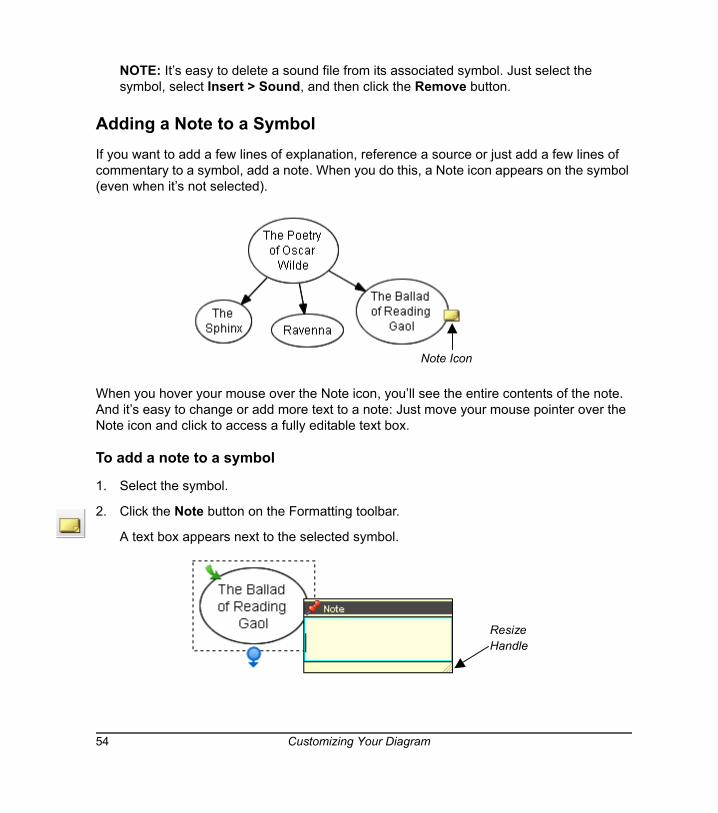
Adding a Note to a SymbolIf you want to add a few lines of explanation, reference a source or just add a few lines of commentary to a symbol, add a note. When you do this, a Note icon appears on the symbol (even when it’s not selected).
When you hover your mouse over the Note icon, you’ll see the entire contents of the note. And it’s easy to change or add more text to a note: Just move your mouse pointer over the Note icon and click to access a fully editable text box.
To add a note to a symbol
1. Select the symbol.
2. Click the Note button on the Formatting toolbar.
A text box appears next to the selected symbol.
Note Icon
ResizeHandle
54 Customizing Your Diagram
3. Type a note.
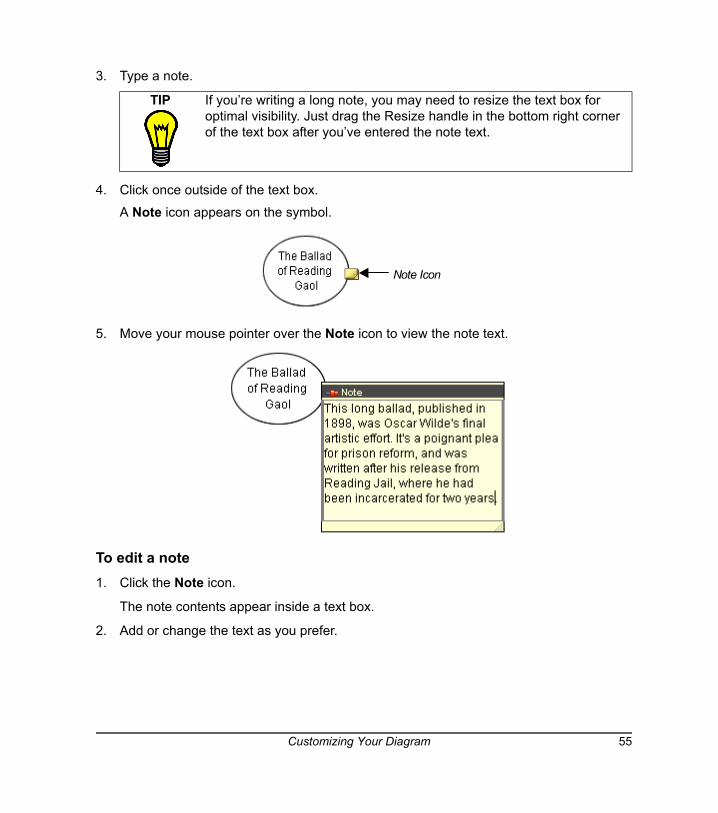
4. Click once outside of the text box.
A Note icon appears on the symbol.
5. Move your mouse pointer over the Note icon to view the note text.
To edit a note1. Click the Note icon.
The note contents appear inside a text box.
2. Add or change the text as you prefer.
TIP If you’re writing a long note, you may need to resize the text box for optimal visibility. Just drag the Resize handle in the bottom right corner of the text box after you’ve entered the note text.
Note Icon
Customizing Your Diagram 55
Click once outside of the text box to commit the text.
To delete a note1. Select the symbol that contains the note you want to delete.
2. Select Delete Note from the Edit menu.
OR
Right-click and select Delete Note.
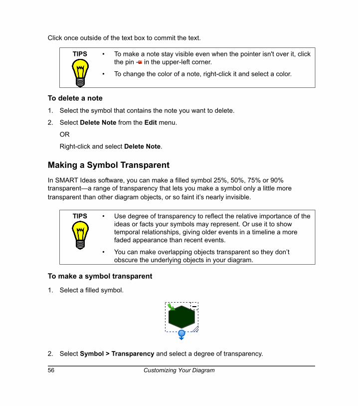
Making a Symbol TransparentIn SMART Ideas software, you can make a filled symbol 25%, 50%, 75% or 90% transparent—a range of transparency that lets you make a symbol only a little more transparent than other diagram objects, or so faint it’s nearly invisible.
To make a symbol transparent
1. Select a filled symbol.
2. Select Symbol > Transparency and select a degree of transparency.
TIPS • To make a note stay visible even when the pointer isn't over it, click the pin in the upper-left corner.
• To change the color of a note, right-click it and select a color.
TIPS • Use degree of transparency to reflect the relative importance of the ideas or facts your symbols may represent. Or use it to show temporal relationships, giving older events in a timeline a more faded appearance than recent events.
• You can make overlapping objects transparent so they don’t obscure the underlying objects in your diagram.
56 Customizing Your Diagram
The transparency for the selected symbol changes accordingly.
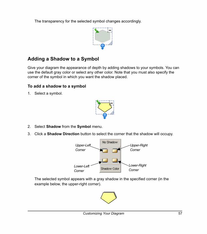
Adding a Shadow to a SymbolGive your diagram the appearance of depth by adding shadows to your symbols. You can use the default gray color or select any other color. Note that you must also specify the corner of the symbol in which you want the shadow placed.
To add a shadow to a symbol1. Select a symbol.
2. Select Shadow from the Symbol menu.
3. Click a Shadow Direction button to select the corner that the shadow will occupy.
The selected symbol appears with a gray shadow in the specified corner (in the example below, the upper-right corner).
Upper-LeftCorner
Upper-RightCorner
Lower-RightCorner
Lower-LeftCorner
Customizing Your Diagram 57
To add a colored shadow to a symbol
1. Select a symbol.
2. Select Shadow from the Symbol menu.
3. Click the Shadow Color button and select a color.
The selected symbol appears with a colored shadow in the last corner specified.
NOTE: The next time you create a shadow, the default shadow color (gray) is restored.
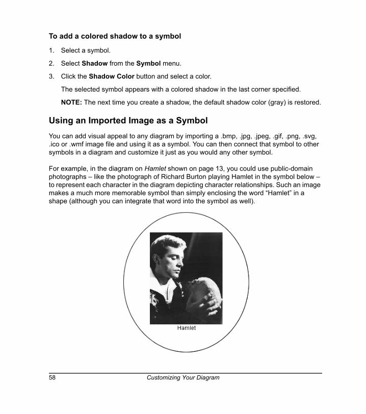
Using an Imported Image as a SymbolYou can add visual appeal to any diagram by importing a .bmp, .jpg, .jpeg, .gif, .png, .svg, .ico or .wmf image file and using it as a symbol. You can then connect that symbol to other symbols in a diagram and customize it just as you would any other symbol.
For example, in the diagram on Hamlet shown on page 13, you could use public-domain photographs – like the photograph of Richard Burton playing Hamlet in the symbol below – to represent each character in the diagram depicting character relationships. Such an image makes a much more memorable symbol than simply enclosing the word “Hamlet” in a shape (although you can integrate that word into the symbol as well).
58 Customizing Your Diagram
To use an imported image as a symbol
1. Select one or more symbols.
2. Select Image from File from the Insert menu.
An Open dialog box appears.
3. Browse to the image file you want to import into the diagram.
NOTE: You can import .bmp, .jpg, .jpeg, .gif, .png, .svg, .ico and .wmf files.
4. Click the Open button.
To add a text label to the image symbol
1. Double-click the image symbol.
A text box appears.
2. Type the text label.
3. Press the ENTER key on your keyboard.
To remove an image from a symbol1. Select the symbol with an image you want to remove.
2. Select Remove Picture from the Edit menu.
OR
Right-click and select Remove Picture.
The image contained within the symbol will disappears.
TIPS Many works of art (excluding most mid-to-late 20th century works) are now in the public domain. Thousands of Internet sits (including national art gallery sites) allow reproductions of their materials for the purpose of scholarship and teaching.
You can use a screen capture tool (such as the Screen Capture tool in Notebook™ software) and your Web browser to surf the Internet and capture images from fine art, literary, historical or scientific sites to integrate into your diagrams. You’ll do more than arouse your students’ interest: They’ll be delighted—and maybe even a little inspired.
Customizing Your Diagram 59
Using Clip Art as a SymbolYou can effortlessly add visual appeal and interest to your diagrams using the extensive collection of clip art images that comes with SMART Ideas software. Clip art images are stored in the Gallery toolbar, and you can drag and drop them into the workspace just as you would with styles in Style Collections.
When you add a clip art image to a diagram, it becomes a symbol you can treat like any other symbol. You can surround the image with symbol shapes, resize it, connect it to other symbols and add text to it.
To use an image from the clip art gallery as a symbol 1. Click the drop-down arrow at the top of the Gallery toolbar and select Clip Art Gallery.
2. Browse through the categories. When you select a category, all the clip art associated with it is displayed in the palette area below.
3. Click and drag a clip art image into the workspace.
OR
Click again on the image.
TIPS You can make your image symbols as elaborate or as simple as you like:
• Change the “frame” around the image by changing the symbol shape. For example, you may prefer a diamond rather than an oval frame around the Hamlet image. Right-click the symbol and select Shape > Diamond.
• Create a colorful matte effect around your symbol. Right-click the image symbol and select Fill Color. Now select a color or a fill effect.
• If you like, dispense with the frame altogether by selecting a shape that’s identical to the image shape. For example, with the rectangular Hamlet image, right-click the symbol and select Shape > Rectangle. The frame inside the symbol disappears.
60 Customizing Your Diagram
4. If the clip art appears smaller than you’d like, click and drag the Resize button to enlarge it. While it’s enlarging, the image may appear somewhat pixelated and unclear, but a nice, high resolution image will be restored when you finish dragging the image.
5. To frame the clip art image with a shape, click the drop-down arrow at the top of the Gallery toolbar and select Style Collections, select a symbol from the Style palette, and then click on the clip art.
Importing Images into the Clip Art Gallery You can integrate your favorite images into your diagrams by importing your own image collections into the clip art gallery. You can import any .jpg, .gif, .png, .bmp, .ico, .wmp or .svg file into the gallery.
You can create your own Clip Art category first, and then add clip art to it, or create the new category at the same time as you import the clip art.
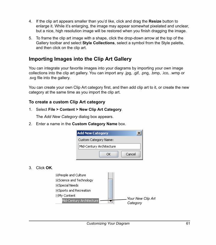
To create a custom Clip Art category1. Select File > Content > New Clip Art Category.
The Add New Category dialog box appears.
2. Enter a name in the Custom Category Name box.
3. Click OK.
Your New Clip Art Category
Customizing Your Diagram 61
Your new Clip Art category is stored in My Documents\My SMART Ideas Content\Clip Art.
To add clip art to a custom Clip Art Category1. Click the drop-down arrow at the top of Gallery toolbar and select Clip Art Gallery.
2. In the Gallery Toolbar, select My Content.
Click the Add Clip Art link in the Style palette.
OR
If the Style palette does not contain the Add Clip Art link, right-click the palette and select Add Clip Art.
The Open dialog box appears.
3. Browse to and select the clip art image you'd like to add.
The Select Category dialog box appears.
4. Click the Custom Categories arrow and select a category for the image(s).
OR
Click the New Category button to create a new category for the image(s).
5. Click OK.
The Clip Art Style palette displays the selected image(s)
To import more free clip art from SMART Technologies1. Select Download More Clip Art from the Help menu.
2. Follow the instructions on downloading and installing the selected clip art collection.
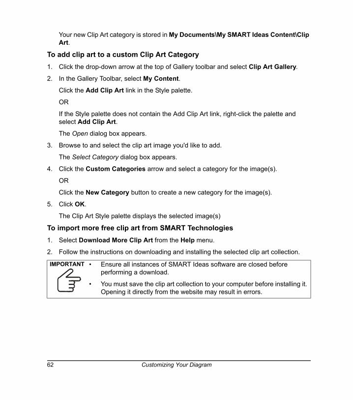
IMPORTANT • Ensure all instances of SMART Ideas software are closed before performing a download.
• You must save the clip art collection to your computer before installing it. Opening it directly from the website may result in errors.
62 Customizing Your Diagram
Searching for Clip Art and ClipletsThe clip art and cliplet gallery provided with SMART Ideas software contains scores of images organized into such subject categories as social studies, language arts, math and science. You can add as many of your own images as you like, resulting in a potentially vast collection of images.
We’ve provided a search engine so you can easily find just the right image. Enter a search term and the Gallery will be searched by filename for matches. If any part of the image filename matches the search term, it will appear in the search results. For example, if you enter ball as a search term, among the search results you’ll find clip art entitled "ball," "ballet" and "balloon."
NOTES:
• You can view the filenames for the .wmf clip art files that comes with SMART Ideas software by hovering the pointer over the images in the palette.
• Any image files you import will be searched by the first part of their filenames (the file extension isn’t necessary). For example, if you import a file called Byron.jpg, enter the keyword “Byron” to find the associated image in the clip art gallery.
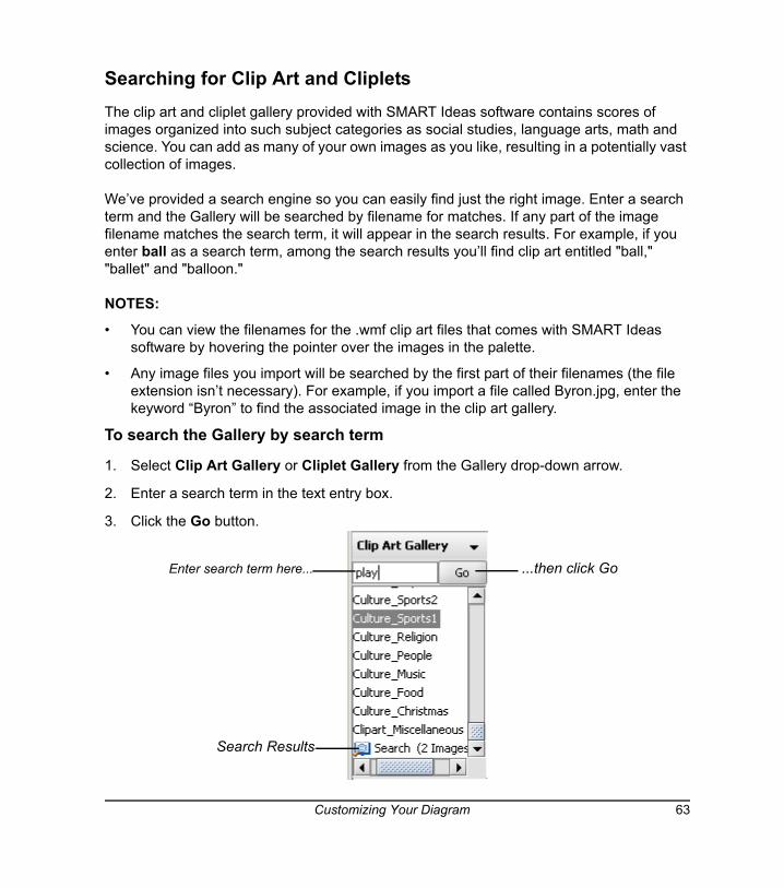
To search the Gallery by search term
1. Select Clip Art Gallery or Cliplet Gallery from the Gallery drop-down arrow.
2. Enter a search term in the text entry box.
3. Click the Go button.
Enter search term here... ...then click Go
Search Results
Customizing Your Diagram 63
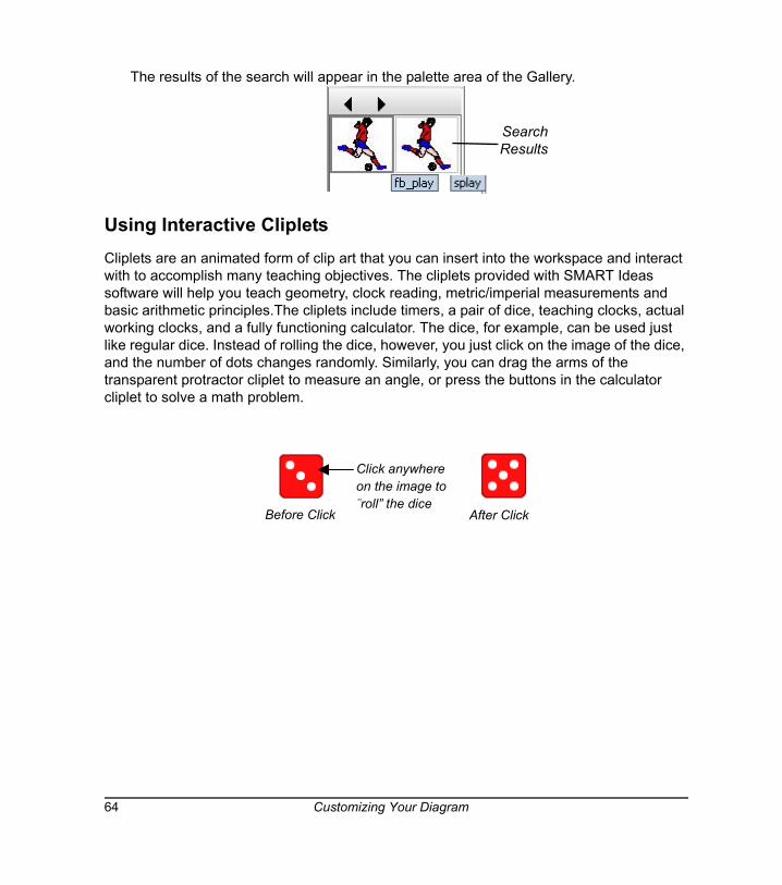
The results of the search will appear in the palette area of the Gallery.
Using Interactive ClipletsCliplets are an animated form of clip art that you can insert into the workspace and interact with to accomplish many teaching objectives. The cliplets provided with SMART Ideas software will help you teach geometry, clock reading, metric/imperial measurements and basic arithmetic principles.The cliplets include timers, a pair of dice, teaching clocks, actual working clocks, and a fully functioning calculator. The dice, for example, can be used just like regular dice. Instead of rolling the dice, however, you just click on the image of the dice, and the number of dots changes randomly. Similarly, you can drag the arms of the transparent protractor cliplet to measure an angle, or press the buttons in the calculator cliplet to solve a math problem.
Search Results
Click anywhereon the image to“roll” the dice
Before Click After Click
64 Customizing Your Diagram
Inserting ClipletsOnce you insert a cliplet, you can click, drag or otherwise manipulate components of the image to fulfill the purpose of the cliplet.
Most cliplets are easier to use if you lock them into place first. Otherwise, you may move the entire cliplet rather than the functional part of the cliplet, such as the protractor arm. To lock cliplets in place, click the Tack button in the upper-left corner of the selected cliplet. Also, you can access Help for those cliplets with complicated functionality by clicking the Help button in the lower-right corner of the selection rectangle.
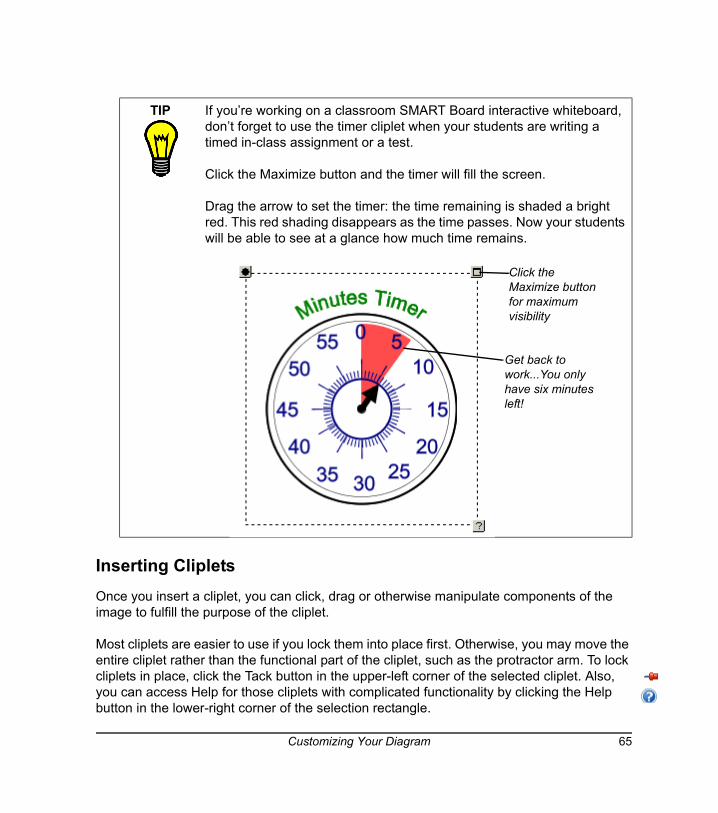
TIP If you’re working on a classroom SMART Board interactive whiteboard, don’t forget to use the timer cliplet when your students are writing a timed in-class assignment or a test.
Click the Maximize button and the timer will fill the screen.
Drag the arrow to set the timer: the time remaining is shaded a bright red. This red shading disappears as the time passes. Now your students will be able to see at a glance how much time remains.
Click the Maximize button for maximum visibility
Get back to work...You only have six minutes left!
Customizing Your Diagram 65
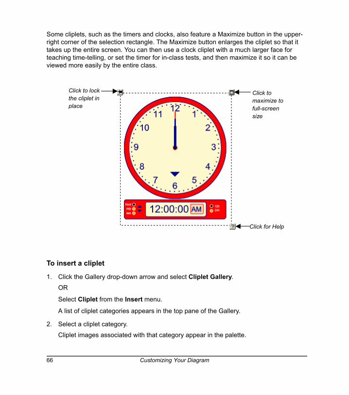
Some cliplets, such as the timers and clocks, also feature a Maximize button in the upper-right corner of the selection rectangle. The Maximize button enlarges the cliplet so that it takes up the entire screen. You can then use a clock cliplet with a much larger face for teaching time-telling, or set the timer for in-class tests, and then maximize it so it can be viewed more easily by the entire class.
To insert a cliplet
1. Click the Gallery drop-down arrow and select Cliplet Gallery.
OR
Select Cliplet from the Insert menu.
A list of cliplet categories appears in the top pane of the Gallery.
2. Select a cliplet category.
Cliplet images associated with that category appear in the palette.
Click to lockthe cliplet inplace
Click for Help
Click tomaximize tofull-screensize
66 Customizing Your Diagram
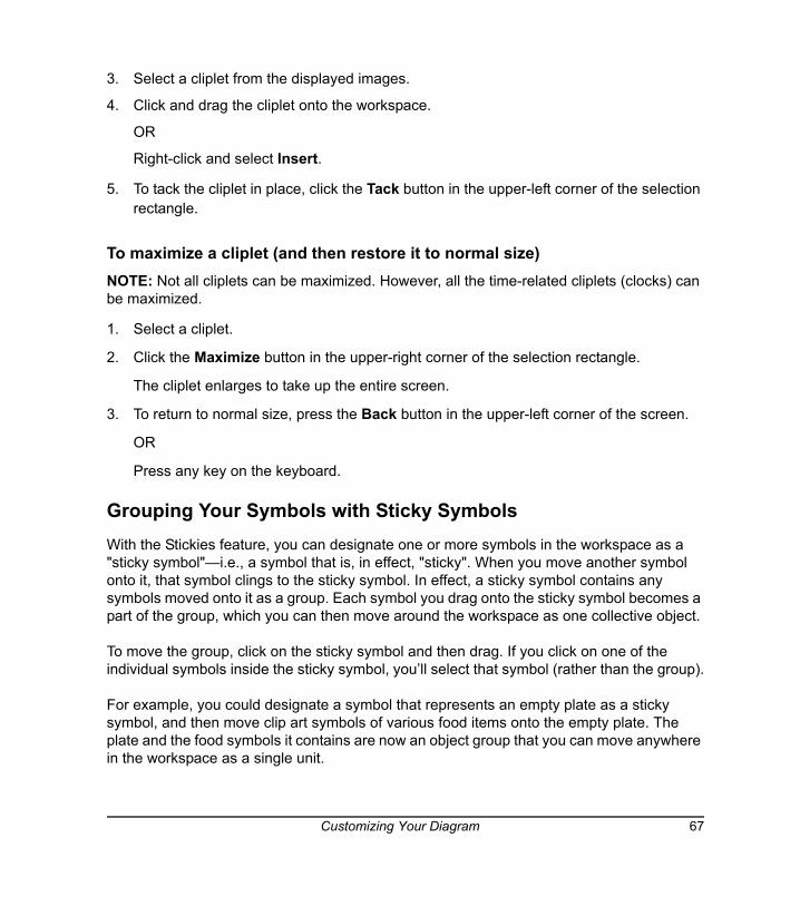
3. Select a cliplet from the displayed images.
4. Click and drag the cliplet onto the workspace.
OR
Right-click and select Insert.
5. To tack the cliplet in place, click the Tack button in the upper-left corner of the selection rectangle.
To maximize a cliplet (and then restore it to normal size)NOTE: Not all cliplets can be maximized. However, all the time-related cliplets (clocks) can be maximized.
1. Select a cliplet.
2. Click the Maximize button in the upper-right corner of the selection rectangle.
The cliplet enlarges to take up the entire screen.
3. To return to normal size, press the Back button in the upper-left corner of the screen.
OR
Press any key on the keyboard.
Grouping Your Symbols with Sticky SymbolsWith the Stickies feature, you can designate one or more symbols in the workspace as a "sticky symbol"—i.e., a symbol that is, in effect, "sticky". When you move another symbol onto it, that symbol clings to the sticky symbol. In effect, a sticky symbol contains any symbols moved onto it as a group. Each symbol you drag onto the sticky symbol becomes a part of the group, which you can then move around the workspace as one collective object.
To move the group, click on the sticky symbol and then drag. If you click on one of the individual symbols inside the sticky symbol, you’ll select that symbol (rather than the group).
For example, you could designate a symbol that represents an empty plate as a sticky symbol, and then move clip art symbols of various food items onto the empty plate. The plate and the food symbols it contains are now an object group that you can move anywhere in the workspace as a single unit.
Customizing Your Diagram 67
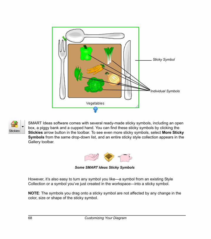
SMART Ideas software comes with several ready-made sticky symbols, including an open box, a piggy bank and a cupped hand. You can find these sticky symbols by clicking the Stickies arrow button in the toolbar. To see even more sticky symbols, select More Sticky Symbols from the same drop-down list, and an entire sticky style collection appears in the Gallery toolbar.
However, it’s also easy to turn any symbol you like—a symbol from an existing Style Collection or a symbol you’ve just created in the workspace—into a sticky symbol.
NOTE: The symbols you drag onto a sticky symbol are not affected by any change in the color, size or shape of the sticky symbol.
Sticky Symbol
Individual Symbols
Some SMART Ideas Sticky Symbols
68 Customizing Your Diagram

To group a collection of symbols with a sticky symbol1. Click the Stickies button drop-down arrow and select a sticky symbol from the list.
The new Sticky symbol appears in the workspace.
OR
To select a sticky symbol that doesn't appear in the drop-down list, select More Sticky Symbols.
A Stickies category appears in the Style Collections. In the Style palette, drag and drop or double-click a Sticky symbol to add it to the workspace.
2. Click and drag one or more symbols onto the sticky symbol.
Each time you drag a symbol onto the sticky symbol it will appear outlined in blue.
3. Click and drag the sticky symbol to move the entire group around the workspace. If you click and drag individual symbols, you’ll move them off the sticky symbol, and they will no longer be a part of the "sticky" group.
To create a sticky symbol1. Select a symbol in the workspace.
2. Click the Stickies arrow button and select Create Sticky Symbol.
OR
Select Tools > Stickies > Create Sticky Symbol.
The symbol appears surrounded by a solid green selection rectangle.
3. Click and drag other symbols onto the sticky symbol you just created.
Customizing Your Diagram 69
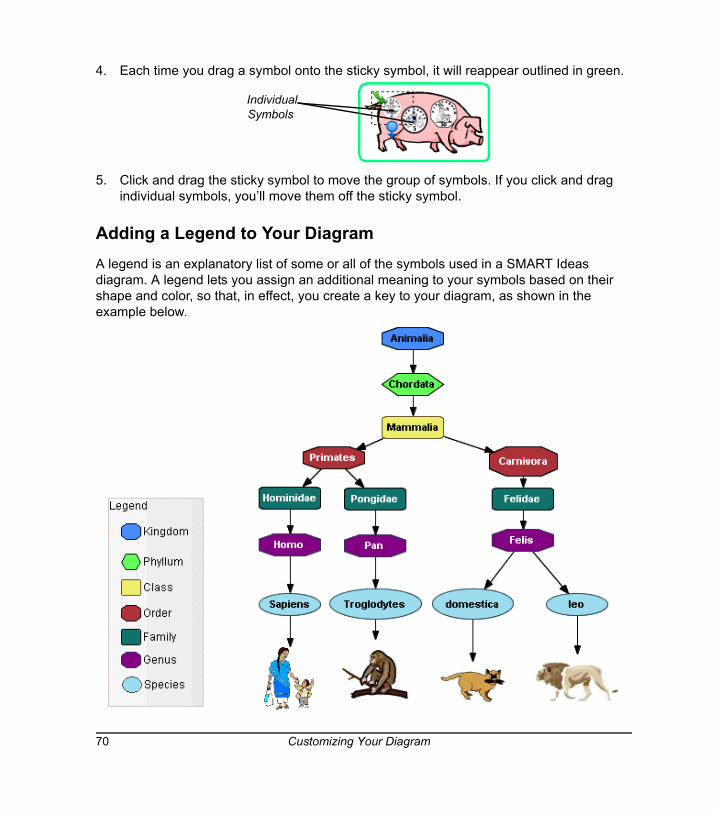
4. Each time you drag a symbol onto the sticky symbol, it will reappear outlined in green.
5. Click and drag the sticky symbol to move the group of symbols. If you click and drag individual symbols, you’ll move them off the sticky symbol.
Adding a Legend to Your DiagramA legend is an explanatory list of some or all of the symbols used in a SMART Ideas diagram. A legend lets you assign an additional meaning to your symbols based on their shape and color, so that, in effect, you create a key to your diagram, as shown in the example below.
Individual Symbols
70 Customizing Your Diagram
The explanatory text beside each symbol comes from from the text label associated with that symbol. So, before dragging a symbol onto the legend, you may want to add or change that text so it serves as explanatory text.
After you've created the legend, you can save it for later use by converting it into a custom Style Collection. When you want to use the legend again, just select that Style Collection and use it as the basis for another legend (using the Insert > Legend > Current Style Collection command).
NOTES:
• If the legend is too big or too small after you've added all the symbols, you can easily resize it, just as you would any other symbol.
• Symbols you add to the legend are grouped with it automatically. When you move the legend, the symbols it contains move with it.
You can create a legend by:
• inserting a blank legend and adding the symbols manually
• creating a legend from the current Style Collection
• using a Style Collection as a legend
Inserting a Blank LegendWhen you insert a blank legend in the workspace, you must then add the symbols to it manually. This is especially useful if you want to create a legend that contains only a few symbols.
To insert a blank legend and add symbols to it1. Select Insert > Legend > Blank.
A blank legend appears in the workspace.
2. Select a symbol in the workspace that you want to use as part of the legend. Add explanatory text to the symbol, or modify existing text so it serves that purpose.
3. Drag the symbol into the legend.
The symbol becomes part of the legend: The symbol text becomes its title, and the title automatically appears to the right of the symbol.
4. Repeat this process for as many symbols as you'd like.
Customizing Your Diagram 71
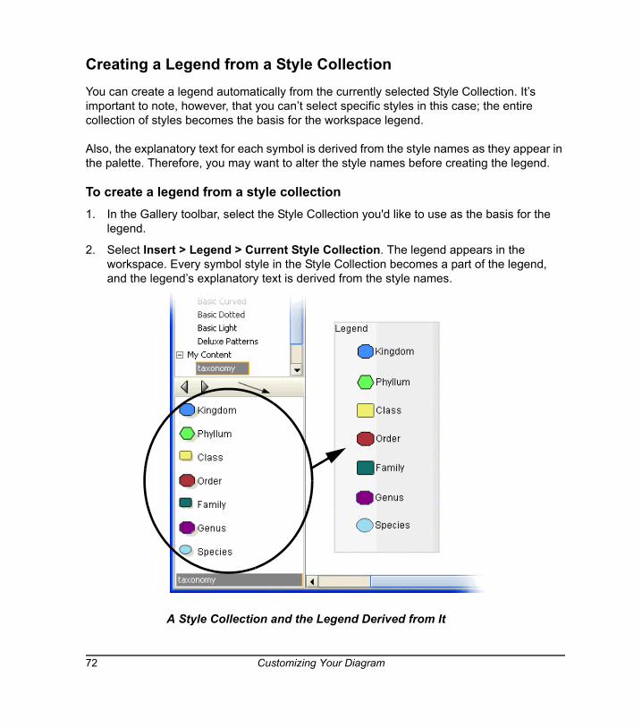
Creating a Legend from a Style CollectionYou can create a legend automatically from the currently selected Style Collection. It’s important to note, however, that you can’t select specific styles in this case; the entire collection of styles becomes the basis for the workspace legend.
Also, the explanatory text for each symbol is derived from the style names as they appear in the palette. Therefore, you may want to alter the style names before creating the legend.
To create a legend from a style collection1. In the Gallery toolbar, select the Style Collection you'd like to use as the basis for the
legend.
2. Select Insert > Legend > Current Style Collection. The legend appears in the workspace. Every symbol style in the Style Collection becomes a part of the legend, and the legend’s explanatory text is derived from the style names.
A Style Collection and the Legend Derived from It
72 Customizing Your Diagram
Converting a Legend to a Custom Style CollectionOnce you've created a legend, you can easily convert it to a new Style Collection or add it to an existing custom Style Collection for later use. Then just select that Style Collection and use it as the basis for another legend (using the Insert > Legend > Current Style Collection command).
When you convert a legend to a custom Style Collection, SMART Ideas software automatically saves it to your computer's hard drive as an .ipr file. You'll find the file in the My Documents\MY SMART Ideas Contents\Collections folder.
To convert a legend to a custom Style Collection1. Right-click the legend and select Add Legend to Gallery.
NOTE: Be sure to right-click the legend and not one of the symbols it contains.
2. Click the New Style Collection button to create and name the new collection.
OR
Select a custom Style Collection to which you'd like to add the legend.
3. Click OK.
The legend becomes a Style Collection in its own right or is added to an existing one.
TIP Many of the Style Collections included with SMART Ideas software use style names that describe a symbol's appearance rather than its meaning. You may want to give the symbols more meaningful names before you use a collection as a basis for the legend.
Customizing Your Diagram 73

74 Customizing Your Diagram
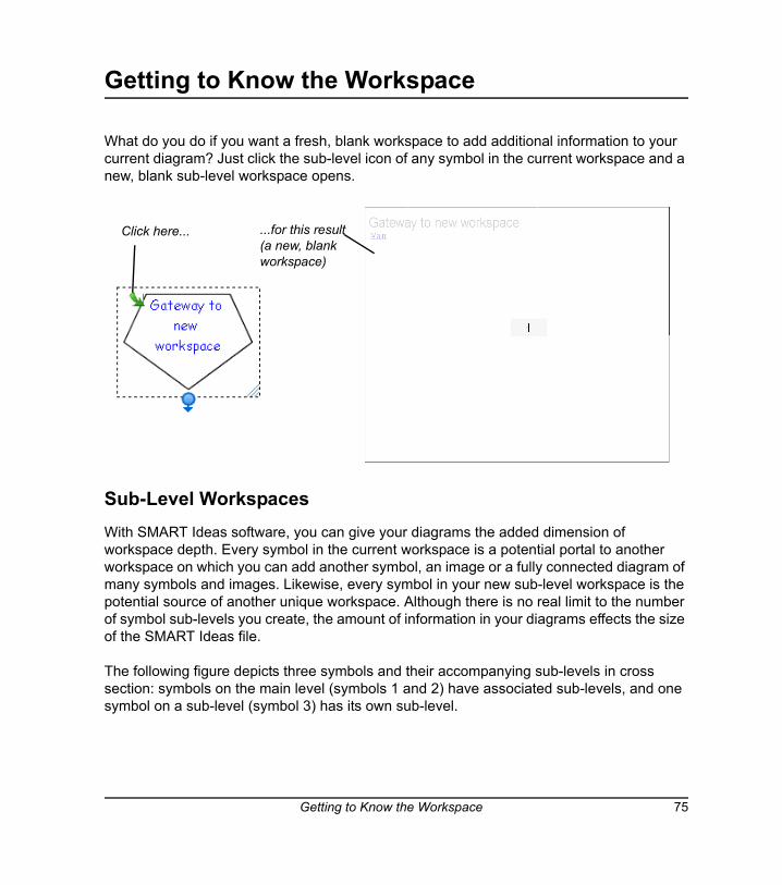
Getting to Know the Workspace
What do you do if you want a fresh, blank workspace to add additional information to your current diagram? Just click the sub-level icon of any symbol in the current workspace and a new, blank sub-level workspace opens.
Sub-Level WorkspacesWith SMART Ideas software, you can give your diagrams the added dimension of workspace depth. Every symbol in the current workspace is a potential portal to another workspace on which you can add another symbol, an image or a fully connected diagram of many symbols and images. Likewise, every symbol in your new sub-level workspace is the potential source of another unique workspace. Although there is no real limit to the number of symbol sub-levels you create, the amount of information in your diagrams effects the size of the SMART Ideas file.
The following figure depicts three symbols and their accompanying sub-levels in cross section: symbols on the main level (symbols 1 and 2) have associated sub-levels, and one symbol on a sub-level (symbol 3) has its own sub-level.
Click here... ...for this result (a new, blank workspace)
Getting to Know the Workspace 75
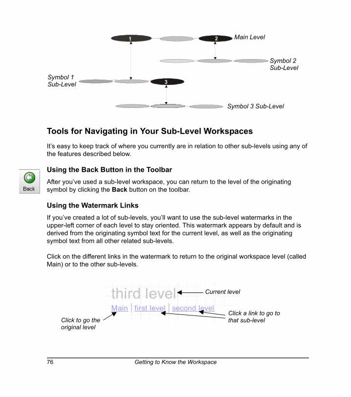
Tools for Navigating in Your Sub-Level WorkspacesIt’s easy to keep track of where you currently are in relation to other sub-levels using any of the features described below.
Using the Back Button in the ToolbarAfter you’ve used a sub-level workspace, you can return to the level of the originating symbol by clicking the Back button on the toolbar.
Using the Watermark LinksIf you’ve created a lot of sub-levels, you’ll want to use the sub-level watermarks in the upper-left corner of each level to stay oriented. This watermark appears by default and is derived from the originating symbol text for the current level, as well as the originating symbol text from all other related sub-levels.
Click on the different links in the watermark to return to the original workspace level (called Main) or to the other sub-levels.
Main Level1
Symbol 1 Sub-Level
2
Symbol 2 Sub-Level
2
3
Symbol 3 Sub-Level
Click a link to go tothat sub-level
Current level
Click to go theoriginal level
76 Getting to Know the Workspace
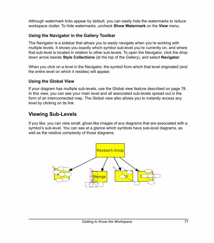
Although watermark links appear by default, you can easily hide the watermarks to reduce workspace clutter. To hide watermarks, uncheck Show Watermark on the View menu.
Using the Navigator in the Gallery ToolbarThe Navigator is a sidebar that allows you to easily navigate when you’re working with multiple levels. It shows you exactly which symbol sub-level you’re currently on, and where that sub-level is located in relation to other sub-levels. To open the Navigator, click the drop-down arrow beside Style Collections (at the top of the Gallery), and select Navigator.
When you click on a level in the Navigator, the symbol from which that level originated (and the entire level on which it resides) will appear.
Using the Global ViewIf your diagram has multiple sub-levels, use the Global view feature described on page 78. In this view, you can see your main level and all associated sub-levels spread out in the form of an interconnected map. The Global view also allows you to instantly access any level by clicking on its link.
Viewing Sub-Levels If you like, you can view small, ghost-like images of any diagrams that are associated with a symbol’s sub-level. You can see at a glance which symbols have sub-level diagrams, as well as the relative complexity of those diagrams.
Getting to Know the Workspace 77
The Show Sub-levels command also allows you to drag a selected symbol into any symbol’s sub-level. For more information on dragging symbols directly into sub-levels, turn to page 100.
To activate the Show Sub-levels command
Check Show Sub-levels on the View menu.
A small, faint image of the sub-level diagram appears inside each originating symbol.
Workspace Views SMART Ideas software provides three distinct views of your work—Diagram, Outline and Global view. You can switch between these views using the tabs at the top of the workspace.
Diagram and Outline ViewThe Diagram view is the view you’ll use most of the time. It’s the default view that gives you the workspace and tools you need for making your diagrams.
To view a text-based, linear counterpart to your diagram, use the Outline view. This view is a ready-made outline that your students can use for organizing a writing project. They can brainstorm and develop connections between ideas in the Diagram view, and then toggle to the Outline view when they’re ready to move from rough ideas to a finished document.
However, the Outline view isn’t just for viewing a text version of your diagram. You can also develop a complete outline from scratch in this view. All the tools for creating new symbols and labeled connectors, adding notes, hyperlinks and sub-levels, rearranging, revising and reformatting your ideas are all available in this view. Any changes you make are immediately reflected in the Diagram view.
Global ViewIf you frequently use sub-level workspaces to create a complex, interconnected web of diagrams, the Global view provides a useful overview of all your work. This view is a three-dimensional depiction in miniature of every diagram at every level, so you can conveniently see everything at once and instantly access any diagram with a mouse click. In addition, the link between the sub-level diagram and its associated upper-level symbol is clearly shown, so it provides a useful road map to your multi-dimensional workspace.
78 Getting to Know the Workspace
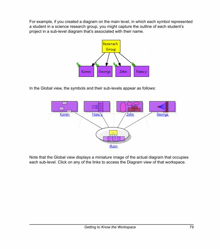
For example, if you created a diagram on the main level, in which each symbol represented a student in a science research group, you might capture the outline of each student’s project in a sub-level diagram that’s associated with their name.
In the Global view, the symbols and their sub-levels appear as follows:
Note that the Global view displays a miniature image of the actual diagram that occupies each sub-level. Click on any of the links to access the Diagram view of that workspace.
Getting to Know the Workspace 79
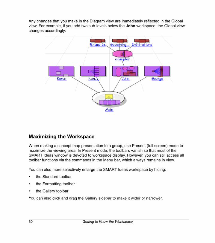
Any changes that you make in the Diagram view are immediately reflected in the Global view. For example, if you add two sub-levels below the John workspace, the Global view changes accordingly:
Maximizing the WorkspaceWhen making a concept map presentation to a group, use Present (full screen) mode to maximize the viewing area. In Present mode, the toolbars vanish so that most of the SMART Ideas window is devoted to workspace display. However, you can still access all toolbar functions via the commands in the Menu bar, which always remains in view.
You can also more selectively enlarge the SMART Ideas workspace by hiding:
• the Standard toolbar
• the Formatting toolbar
• the Gallery toolbar
You can also click and drag the Gallery sidebar to make it wider or narrower.
80 Getting to Know the Workspace
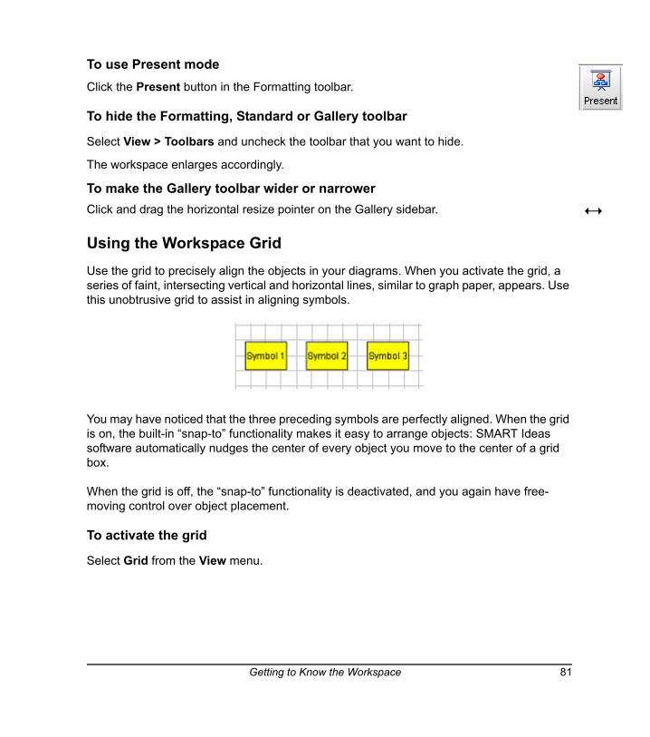
To use Present modeClick the Present button in the Formatting toolbar.
To hide the Formatting, Standard or Gallery toolbar
Select View > Toolbars and uncheck the toolbar that you want to hide.
The workspace enlarges accordingly.
To make the Gallery toolbar wider or narrowerClick and drag the horizontal resize pointer on the Gallery sidebar.
Using the Workspace GridUse the grid to precisely align the objects in your diagrams. When you activate the grid, a series of faint, intersecting vertical and horizontal lines, similar to graph paper, appears. Use this unobtrusive grid to assist in aligning symbols.
You may have noticed that the three preceding symbols are perfectly aligned. When the grid is on, the built-in “snap-to” functionality makes it easy to arrange objects: SMART Ideas software automatically nudges the center of every object you move to the center of a grid box.
When the grid is off, the “snap-to” functionality is deactivated, and you again have free-moving control over object placement.
To activate the grid
Select Grid from the View menu.
Getting to Know the Workspace 81
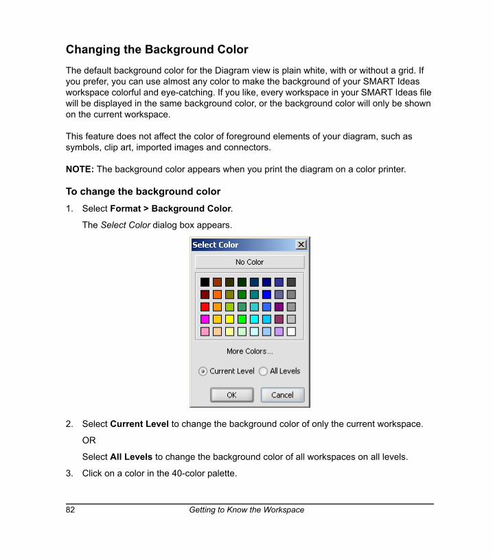
Changing the Background Color The default background color for the Diagram view is plain white, with or without a grid. If you prefer, you can use almost any color to make the background of your SMART Ideas workspace colorful and eye-catching. If you like, every workspace in your SMART Ideas file will be displayed in the same background color, or the background color will only be shown on the current workspace.
This feature does not affect the color of foreground elements of your diagram, such as symbols, clip art, imported images and connectors.
NOTE: The background color appears when you print the diagram on a color printer.
To change the background color1. Select Format > Background Color.
The Select Color dialog box appears.
2. Select Current Level to change the background color of only the current workspace.
OR
Select All Levels to change the background color of all workspaces on all levels.
3. Click on a color in the 40-color palette.
82 Getting to Know the Workspace

OR
To create a custom color, click More Colors.
The Choose Color dialog box appears.
4. Click anywhere on the color swatch to change the hue and saturation, and then move the slider in the color gradient to change the luminescence (brightness). Alternatively, you can change the Red, Green and Blue values by selecting or entering number values.
5. Click OK.
To remove the background color1. Select Background Color from the Format menu.
The Select Color dialog box appears.
2. Click the No Color button.
The background color disappears from the current and from all sub-level workspaces as well.
Move the slider to adjust brightness
Click anywhere to change hue and saturation
Preview area
Getting to Know the Workspace 83
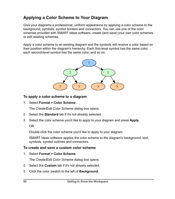
Applying a Color Scheme to Your DiagramGive your diagrams a professional, uniform appearance by applying a color scheme to the background, symbols, symbol borders and connectors. You can use one of the color schemes provided with SMART Ideas software, create (and save) your own color schemes or edit existing schemes.
Apply a color scheme to an existing diagram and the symbols will receive a color based on their position within the diagram's hierarchy. Each first-level symbol has the same color, each second-level symbol has the same color, and so on.
To apply a color scheme to a diagram1. Select Format > Color Scheme.
The Create/Edit Color Scheme dialog box opens.
2. Select the Standard tab if it's not already selected.
3. Select the color scheme you'd like to apply to your diagram and press Apply.
OR
Double-click the color scheme you'd like to apply to your diagram.
SMART Ideas software applies the color scheme to the diagram's background, text, symbols, symbol outlines and connectors.
To create and save a custom color scheme1. Select Format > Color Scheme.
The Create/Edit Color Scheme dialog box opens.
2. Select the Custom tab if it's not already selected.
3. Click the color swatch to the left of Background.
84 Getting to Know the Workspace
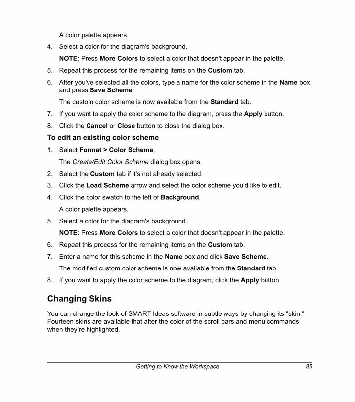
A color palette appears.
4. Select a color for the diagram's background.
NOTE: Press More Colors to select a color that doesn't appear in the palette.
5. Repeat this process for the remaining items on the Custom tab.
6. After you've selected all the colors, type a name for the color scheme in the Name box and press Save Scheme.
The custom color scheme is now available from the Standard tab.
7. If you want to apply the color scheme to the diagram, press the Apply button.
8. Click the Cancel or Close button to close the dialog box.
To edit an existing color scheme1. Select Format > Color Scheme.
The Create/Edit Color Scheme dialog box opens.
2. Select the Custom tab if it's not already selected.
3. Click the Load Scheme arrow and select the color scheme you'd like to edit.
4. Click the color swatch to the left of Background.
A color palette appears.
5. Select a color for the diagram's background.
NOTE: Press More Colors to select a color that doesn't appear in the palette.
6. Repeat this process for the remaining items on the Custom tab.
7. Enter a name for this scheme in the Name box and click Save Scheme.
The modified custom color scheme is now available from the Standard tab.
8. If you want to apply the color scheme to the diagram, click the Apply button.
Changing SkinsYou can change the look of SMART Ideas software in subtle ways by changing its "skin." Fourteen skins are available that alter the color of the scroll bars and menu commands when they’re highlighted.
Getting to Know the Workspace 85
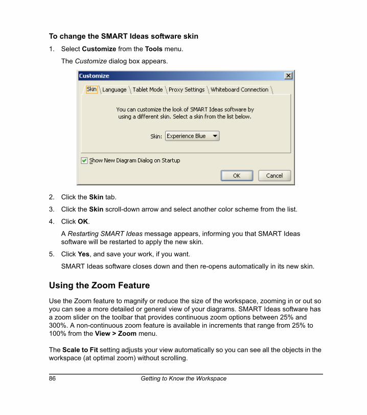
To change the SMART Ideas software skin1. Select Customize from the Tools menu.
The Customize dialog box appears.
2. Click the Skin tab.
3. Click the Skin scroll-down arrow and select another color scheme from the list.
4. Click OK.
A Restarting SMART Ideas message appears, informing you that SMART Ideas software will be restarted to apply the new skin.
5. Click Yes, and save your work, if you want.
SMART Ideas software closes down and then re-opens automatically in its new skin.
Using the Zoom FeatureUse the Zoom feature to magnify or reduce the size of the workspace, zooming in or out so you can see a more detailed or general view of your diagrams. SMART Ideas software has a zoom slider on the toolbar that provides continuous zoom options between 25% and 300%. A non-continuous zoom feature is available in increments that range from 25% to 100% from the View > Zoom menu.
The Scale to Fit setting adjusts your view automatically so you can see all the objects in the workspace (at optimal zoom) without scrolling.
86 Getting to Know the Workspace
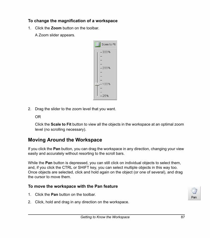
To change the magnification of a workspace1. Click the Zoom button on the toolbar.
A Zoom slider appears.
2. Drag the slider to the zoom level that you want.
OR
Click the Scale to Fit button to view all the objects in the workspace at an optimal zoom level (no scrolling necessary).
Moving Around the Workspace If you click the Pan button, you can drag the workspace in any direction, changing your view easily and accurately without resorting to the scroll bars.
While the Pan button is depressed, you can still click on individual objects to select them, and, if you click the CTRL or SHIFT key, you can select multiple objects in this way too. Once objects are selected, click and hold again on the object (or one of several), and drag the cursor to move them.
To move the workspace with the Pan feature
1. Click the Pan button on the toolbar.
2. Click, hold and drag in any direction on the workspace.
Getting to Know the Workspace 87
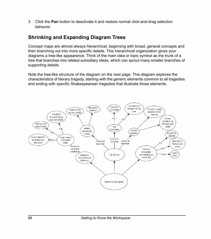
3. Click the Pan button to deactivate it and restore normal click-and-drag selection behavior.
Shrinking and Expanding Diagram Trees Concept maps are almost always hierarchical, beginning with broad, general concepts and then branching out into more specific details. This hierarchical organization gives your diagrams a tree-like appearance. Think of the main idea or topic symbol as the trunk of a tree that branches into related subsidiary ideas, which can sprout many smaller branches of supporting details.
Note the tree-like structure of the diagram on the next page. This diagram explores the characteristics of literary tragedy, starting with the generic elements common to all tragedies and ending with specific Shakespearean tragedies that illustrate those elements.
88 Getting to Know the Workspace
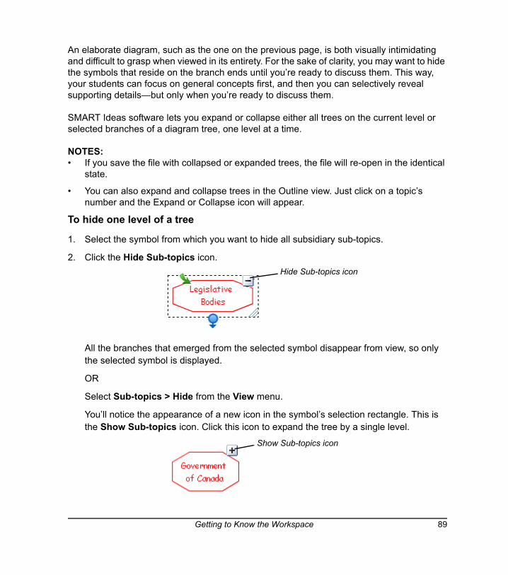
An elaborate diagram, such as the one on the previous page, is both visually intimidating and difficult to grasp when viewed in its entirety. For the sake of clarity, you may want to hide the symbols that reside on the branch ends until you’re ready to discuss them. This way, your students can focus on general concepts first, and then you can selectively reveal supporting details—but only when you’re ready to discuss them.
SMART Ideas software lets you expand or collapse either all trees on the current level or selected branches of a diagram tree, one level at a time.
NOTES: • If you save the file with collapsed or expanded trees, the file will re-open in the identical
state.
• You can also expand and collapse trees in the Outline view. Just click on a topic’s number and the Expand or Collapse icon will appear.
To hide one level of a tree
1. Select the symbol from which you want to hide all subsidiary sub-topics.
2. Click the Hide Sub-topics icon.
All the branches that emerged from the selected symbol disappear from view, so only the selected symbol is displayed.
OR
Select Sub-topics > Hide from the View menu.
You’ll notice the appearance of a new icon in the symbol’s selection rectangle. This is the Show Sub-topics icon. Click this icon to expand the tree by a single level.
Hide Sub-topics icon
Show Sub-topics icon
Getting to Know the Workspace 89
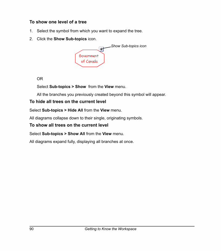
To show one level of a tree
1. Select the symbol from which you want to expand the tree.
2. Click the Show Sub-topics icon.
OR
Select Sub-topics > Show from the View menu.
All the branches you previously created beyond this symbol will appear.
To hide all trees on the current level
Select Sub-topics > Hide All from the View menu.
All diagrams collapse down to their single, originating symbols.
To show all trees on the current level
Select Sub-topics > Show All from the View menu.
All diagrams expand fully, displaying all branches at once.
Show Sub-topics icon
90 Getting to Know the Workspace
Working with Text
Symbols and connectors can be labeled with titles or descriptive text to make your diagram more meaningful to others.
To facilitate adding and changing text, SMART Ideas software lets you:
• perform full text editing and formatting (this page)
• check your spelling (page 92)
• find and replace text (page 94)
Editing TextIt’s easy to edit the text labels for symbols and connectors. Simply select the object and then click once (or right-click the object and select Edit Label).
Then just enter the text and select it for subsequent editing as you would in a word processing program. When you’re finished, press the ENTER key on your keyboard. If you want to add a blank line within the symbol to separate text, press ALT+ENTER on your keyboard.
To insert a blank line (a.k.a. carriage or hard return)
1. Type some text on the SMART Ideas workspace or in a selected symbol’s text box.
NOTE: Do not press the ENTER key on the keyboard.
2. Press the ALT+ENTER keys on the keyboard twice.
A blank line (hard return) will appear.
To edit object labels
1. Select a symbol or connector.
2. Click the selected object again and edit the text in the text box that appears.
OR
Right-click on the selected object, select Edit Label, and edit the text in the text box that appears.
Working with Text 91
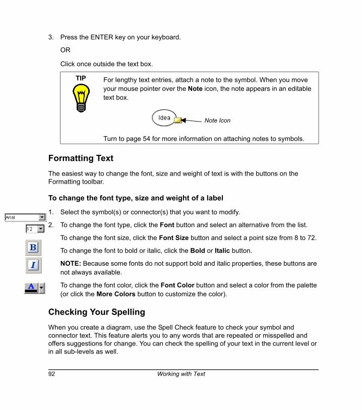
3. Press the ENTER key on your keyboard.
OR
Click once outside the text box.
Formatting TextThe easiest way to change the font, size and weight of text is with the buttons on the Formatting toolbar.
To change the font type, size and weight of a label
1. Select the symbol(s) or connector(s) that you want to modify.
2. To change the font type, click the Font button and select an alternative from the list.
To change the font size, click the Font Size button and select a point size from 8 to 72.
To change the font to bold or italic, click the Bold or Italic button.
NOTE: Because some fonts do not support bold and italic properties, these buttons are not always available.
To change the font color, click the Font Color button and select a color from the palette (or click the More Colors button to customize the color).
Checking Your SpellingWhen you create a diagram, use the Spell Check feature to check your symbol and connector text. This feature alerts you to any words that are repeated or misspelled and offers suggestions for change. You can check the spelling of your text in the current level or in all sub-levels as well.
TIP For lengthy text entries, attach a note to the symbol. When you move your mouse pointer over the Note icon, the note appears in an editable text box.
Turn to page 54 for more information on attaching notes to symbols.
Note Icon
92 Working with Text
To check your spelling
1. Select Spell Check > Current Level or Spell Check > All Levels from the Tools menu.
When a misspelled or repeated word is encountered, the Check Spelling dialog box appears.
A misspelled or repeated word appears in the Not in dictionary box and a suggestion for change appears in the Change to box.
If no errors are found, a message appears telling you that the spell check is complete.
2. Accept or reject the results of the spell check as follows:
a. To accept the suggested word, click the Change button.
OR
Select a word from the Suggestions list and click the Change or Change All buttons.
OR
Type a correction of your own in the Change to field and click the Change or Change All buttons.
b. To retain the original word (ignoring the spell check feature’s advice), click the Ignore button, or click the Ignore All button to retain every occurrence of the original spelling.
c. To add the word to the Spell Check dictionary, click the Add button.
When the Spell Check is complete, the Check Spelling dialog box disappears.
To change the Spell Check dictionary1. Click the scroll-down arrow under Dictionary language.
2. Select another dictionary from the list.
Working with Text 93
Finding and Replacing TextWhen you need to review or change text in either the Diagram view or the Outline view, use the Find Text and Replace Text commands in the Edit menu. Find Text helps you locate occurrences of any text you specify. You can search for and replace text in just the current workspace or include all sub-levels as well.
To find text
1. Select Find Text from the Edit menu.
The Find dialog box appears at the bottom of the workspace.
2. Enter the text that you want to find in the Text to find box.
You can type up to 255 characters in this box. The text scrolls horizontally as you type.
3. To find only separate words (not characters embedded in other words), select Whole words only. For example, select this option to find “run” but not “running.”
4. To find only words that have a specific pattern of uppercase and lowercase characters, select Match case.
5. To restrict your search to the current level only, select Current level. To expand your search to include all sub-levels as well, select All levels.
6. Click the Search button.
SMART Ideas software selects the first occurrence of the text in either a symbol or connector label. The text is displayed as it appears in relation to other levels in bold text in the display area.
If the word or phrase isn't found, a No Search Result message appears in the display area.
7. Click the Next button to find subsequent occurrences of the text.
8. Click the Hide button in the upper-right corner of the Find dialog box to close the dialog.
To replace text1. Select Replace Text from the Edit menu.
The Find dialog box appears at the bottom of the workspace.
2. Enter the text that you want to replace in the Text to find box.
You can type up to 255 characters in this box. The text scrolls horizontally as you type.
94 Working with Text
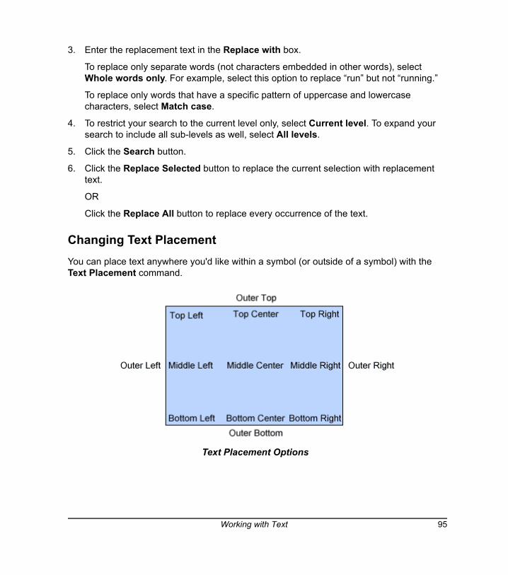
3. Enter the replacement text in the Replace with box.
To replace only separate words (not characters embedded in other words), select Whole words only. For example, select this option to replace “run” but not “running.”
To replace only words that have a specific pattern of uppercase and lowercase characters, select Match case.
4. To restrict your search to the current level only, select Current level. To expand your search to include all sub-levels as well, select All levels.
5. Click the Search button.
6. Click the Replace Selected button to replace the current selection with replacement text.
OR
Click the Replace All button to replace every occurrence of the text.
Changing Text PlacementYou can place text anywhere you'd like within a symbol (or outside of a symbol) with the Text Placement command.
Text Placement Options
Working with Text 95
To change the placement of a symbol's text1. Select the symbol or symbols that contain text.
2. Select Symbol > Text Placement.
OR
Press the Text Placement button drop-down arrow.
Select one of the 13 options for text placement.
NOTES:
• If you select more than one symbol, the same text placement is applied to each.
• The Text Placement button changes appearance to show the text placement for the currently selected symbol.
• If you select a text placement option while no symbol is selected, that placement applies to the next symbol you create.
TIP Use the Outer Top placement to create a title for a symbol.
Use the Outer Bottom placement to create a caption.
96 Working with Text
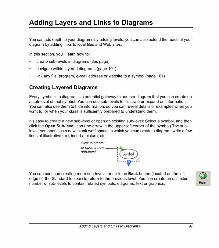
Adding Layers and Links to Diagrams
You can add depth to your diagrams by adding levels; you can also extend the reach of your diagram by adding links to local files and Web sites.
In this section, you’ll learn how to:
• create sub-levels in diagrams (this page)
• navigate within layered diagrams (page 101)
• link any file, program, e-mail address or website to a symbol (page 101)
Creating Layered DiagramsEvery symbol in a diagram is a potential gateway to another diagram that you can create on a sub-level of that symbol. You can use sub-levels to illustrate or expand on information. You can also use them to hide information, so you can reveal details or examples when you want to, or when your class is sufficiently prepared to understand them.
It’s easy to create a new sub-level or open an existing sub-level: Select a symbol, and then click the Open Sub-level icon (the arrow in the upper-left corner of the symbol).The sub-level then opens as a new, blank workspace, in which you can create a diagram, write a few lines of illustrative text, insert a picture, etc.
You can continue creating more sub-levels, or click the Back button (located on the left edge of the Standard toolbar) to return to the previous level. You can create an unlimited number of sub-levels to contain related symbols, diagrams, text or graphics.
Click to create or open a new sub-level
Adding Layers and Links to Diagrams 97
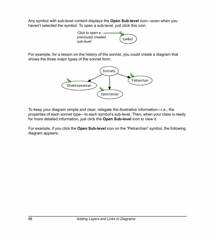
Any symbol with sub-level content displays the Open Sub-level icon—even when you haven’t selected the symbol. To open a sub-level, just click this icon.
For example, for a lesson on the history of the sonnet, you could create a diagram that shows the three major types of the sonnet form.
To keep your diagram simple and clear, relegate the illustrative information—i.e., the properties of each sonnet type—to each symbol’s sub-level. Then, when your class is ready for more detailed information, just click the Open Sub-level icon to view it.
For example, if you click the Open Sub-level icon on the “Petrarchan” symbol, the following diagram appears:
Click to open a previously created sub-level
98 Adding Layers and Links to Diagrams
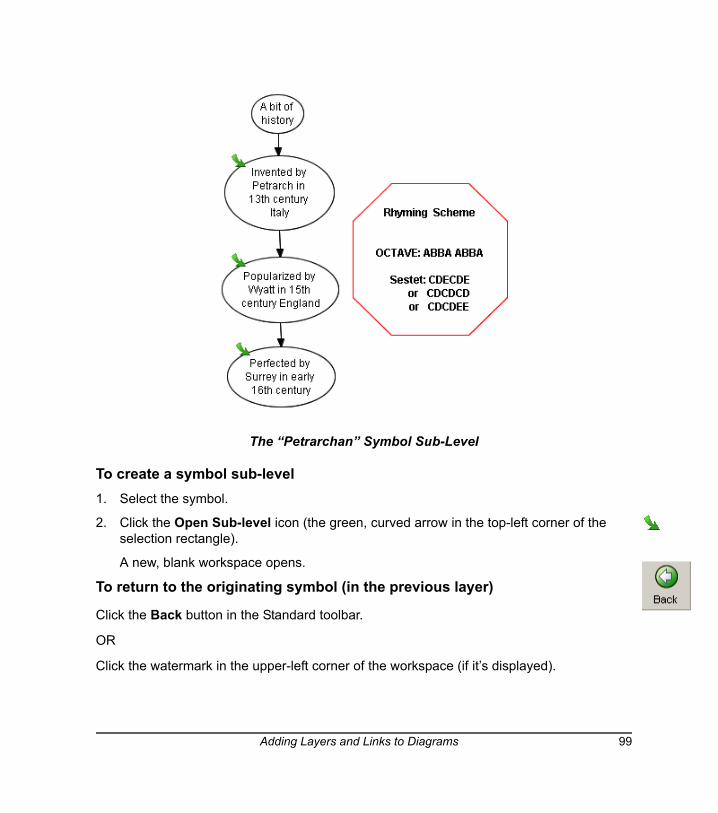
The “Petrarchan” Symbol Sub-Level
To create a symbol sub-level1. Select the symbol.
2. Click the Open Sub-level icon (the green, curved arrow in the top-left corner of the selection rectangle).
A new, blank workspace opens.
To return to the originating symbol (in the previous layer)
Click the Back button in the Standard toolbar.
OR
Click the watermark in the upper-left corner of the workspace (if it’s displayed).
Adding Layers and Links to Diagrams 99
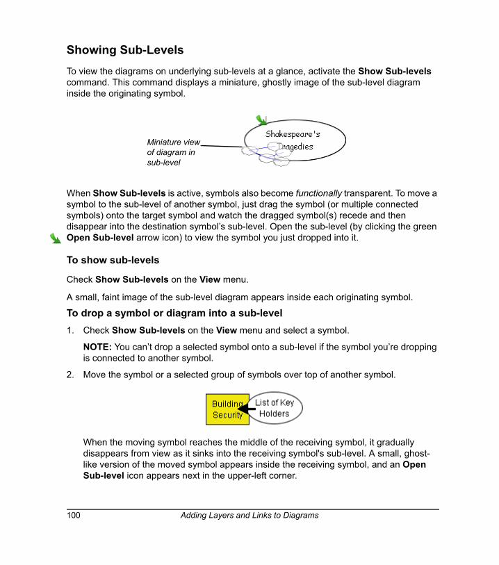
Showing Sub-LevelsTo view the diagrams on underlying sub-levels at a glance, activate the Show Sub-levels command. This command displays a miniature, ghostly image of the sub-level diagram inside the originating symbol.
When Show Sub-levels is active, symbols also become functionally transparent. To move a symbol to the sub-level of another symbol, just drag the symbol (or multiple connected symbols) onto the target symbol and watch the dragged symbol(s) recede and then disappear into the destination symbol’s sub-level. Open the sub-level (by clicking the green Open Sub-level arrow icon) to view the symbol you just dropped into it.
To show sub-levels
Check Show Sub-levels on the View menu.
A small, faint image of the sub-level diagram appears inside each originating symbol.
To drop a symbol or diagram into a sub-level1. Check Show Sub-levels on the View menu and select a symbol.
NOTE: You can’t drop a selected symbol onto a sub-level if the symbol you’re dropping is connected to another symbol.
2. Move the symbol or a selected group of symbols over top of another symbol.
When the moving symbol reaches the middle of the receiving symbol, it gradually disappears from view as it sinks into the receiving symbol's sub-level. A small, ghost-like version of the moved symbol appears inside the receiving symbol, and an Open Sub-level icon appears next in the upper-left corner.
Miniature view of diagram in sub-level
100 Adding Layers and Links to Diagrams
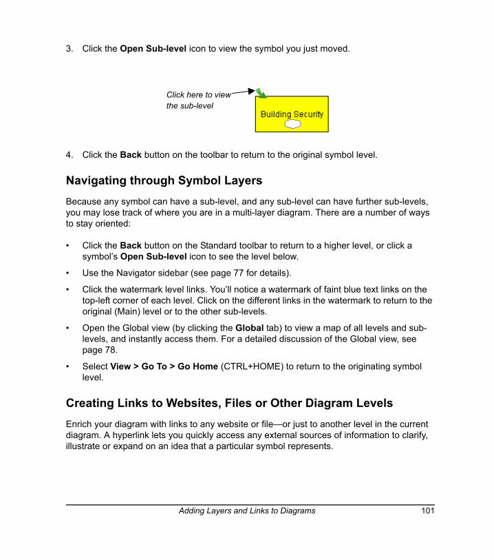
3. Click the Open Sub-level icon to view the symbol you just moved.
4. Click the Back button on the toolbar to return to the original symbol level.
Navigating through Symbol LayersBecause any symbol can have a sub-level, and any sub-level can have further sub-levels, you may lose track of where you are in a multi-layer diagram. There are a number of ways to stay oriented:
• Click the Back button on the Standard toolbar to return to a higher level, or click a symbol’s Open Sub-level icon to see the level below.
• Use the Navigator sidebar (see page 77 for details).
• Click the watermark level links. You’ll notice a watermark of faint blue text links on the top-left corner of each level. Click on the different links in the watermark to return to the original (Main) level or to the other sub-levels.
• Open the Global view (by clicking the Global tab) to view a map of all levels and sub-levels, and instantly access them. For a detailed discussion of the Global view, see page 78.
• Select View > Go To > Go Home (CTRL+HOME) to return to the originating symbol level.
Creating Links to Websites, Files or Other Diagram LevelsEnrich your diagram with links to any website or file—or just to another level in the current diagram. A hyperlink lets you quickly access any external sources of information to clarify, illustrate or expand on an idea that a particular symbol represents.
Click here to viewthe sub-level
Adding Layers and Links to Diagrams 101
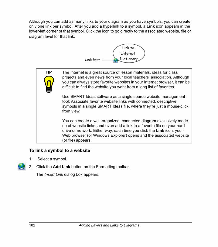
Although you can add as many links to your diagram as you have symbols, you can create only one link per symbol. After you add a hyperlink to a symbol, a Link icon appears in the lower-left corner of that symbol. Click the icon to go directly to the associated website, file or diagram level for that link.
To link a symbol to a website
1. Select a symbol.
2. Click the Add Link button on the Formatting toolbar.
The Insert Link dialog box appears.
TIP The Internet is a great source of lesson materials, ideas for class projects and even news from your local teachers’ association. Although you can always store favorite websites in your Internet browser, it can be difficult to find the website you want from a long list of favorites.
Use SMART Ideas software as a single source website management tool: Associate favorite website links with connected, descriptive symbols in a single SMART Ideas file, where they’re just a mouse-click from view.
You can create a well-organized, connected diagram exclusively made up of website links, and even add a link to a favorite file on your hard drive or network. Either way, each time you click the Link icon, your Web browser (or Windows Explorer) opens and the associated website (or file) appears.
Link Icon
102 Adding Layers and Links to Diagrams
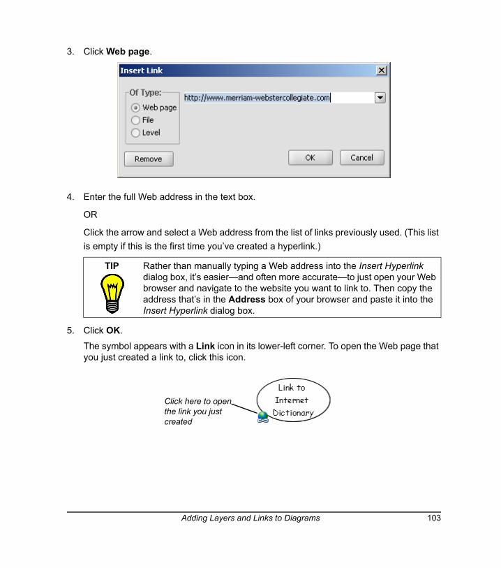
3. Click Web page.
4. Enter the full Web address in the text box.
OR
Click the arrow and select a Web address from the list of links previously used. (This list is empty if this is the first time you’ve created a hyperlink.)
5. Click OK.
The symbol appears with a Link icon in its lower-left corner. To open the Web page that you just created a link to, click this icon.
TIP Rather than manually typing a Web address into the Insert Hyperlink dialog box, it’s easier—and often more accurate—to just open your Web browser and navigate to the website you want to link to. Then copy the address that’s in the Address box of your browser and paste it into the Insert Hyperlink dialog box.
Click here to open the link you just created
Adding Layers and Links to Diagrams 103
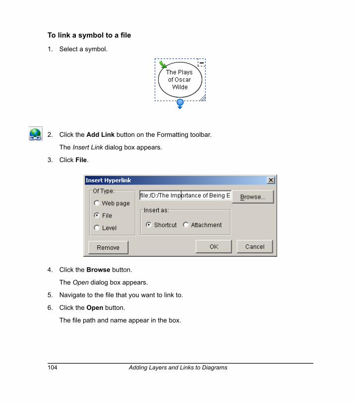
To link a symbol to a file
1. Select a symbol.
2. Click the Add Link button on the Formatting toolbar.
The Insert Link dialog box appears.
3. Click File.
4. Click the Browse button.
The Open dialog box appears.
5. Navigate to the file that you want to link to.
6. Click the Open button.
The file path and name appear in the box.
104 Adding Layers and Links to Diagrams
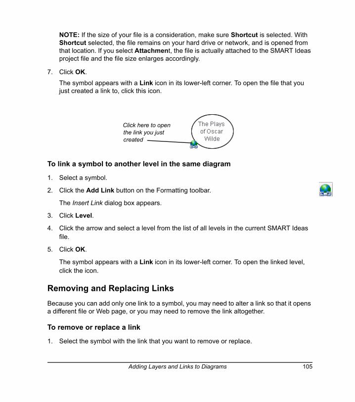
NOTE: If the size of your file is a consideration, make sure Shortcut is selected. With Shortcut selected, the file remains on your hard drive or network, and is opened from that location. If you select Attachment, the file is actually attached to the SMART Ideas project file and the file size enlarges accordingly.
7. Click OK.
The symbol appears with a Link icon in its lower-left corner. To open the file that you just created a link to, click this icon.
To link a symbol to another level in the same diagram
1. Select a symbol.
2. Click the Add Link button on the Formatting toolbar.
The Insert Link dialog box appears.
3. Click Level.
4. Click the arrow and select a level from the list of all levels in the current SMART Ideas file.
5. Click OK.
The symbol appears with a Link icon in its lower-left corner. To open the linked level, click the icon.
Removing and Replacing Links Because you can add only one link to a symbol, you may need to alter a link so that it opens a different file or Web page, or you may need to remove the link altogether.
To remove or replace a link
1. Select the symbol with the link that you want to remove or replace.
Click here to open the link you just created
Adding Layers and Links to Diagrams 105
2. Click the Link button on the Formatting toolbar.
The Insert Hyperlink dialog box appears.
3. To remove the link, click the Remove button.
OR
To replace the link, click a new link type (Web page, File, or Level), and then enter a new Web address, or browse to a new file or diagram level.
4. Click OK.
106 Adding Layers and Links to Diagrams
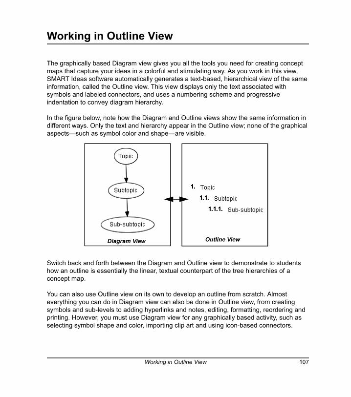
Working in Outline View
The graphically based Diagram view gives you all the tools you need for creating concept maps that capture your ideas in a colorful and stimulating way. As you work in this view, SMART Ideas software automatically generates a text-based, hierarchical view of the same information, called the Outline view. This view displays only the text associated with symbols and labeled connectors, and uses a numbering scheme and progressive indentation to convey diagram hierarchy.
In the figure below, note how the Diagram and Outline views show the same information in different ways. Only the text and hierarchy appear in the Outline view; none of the graphical aspects—such as symbol color and shape—are visible.
Switch back and forth between the Diagram and Outline view to demonstrate to students how an outline is essentially the linear, textual counterpart of the tree hierarchies of a concept map.
You can also use Outline view on its own to develop an outline from scratch. Almost everything you can do in Diagram view can also be done in Outline view, from creating symbols and sub-levels to adding hyperlinks and notes, editing, formatting, reordering and printing. However, you must use Diagram view for any graphically based activity, such as selecting symbol shape and color, importing clip art and using icon-based connectors.
Diagram View Outline View
Working in Outline View 107
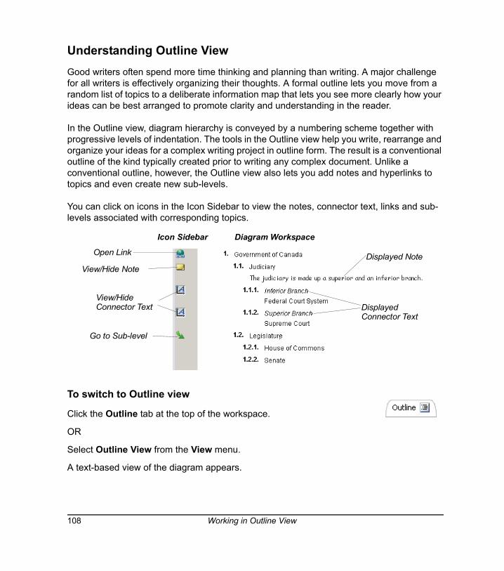
Understanding Outline ViewGood writers often spend more time thinking and planning than writing. A major challenge for all writers is effectively organizing their thoughts. A formal outline lets you move from a random list of topics to a deliberate information map that lets you see more clearly how your ideas can be best arranged to promote clarity and understanding in the reader.
In the Outline view, diagram hierarchy is conveyed by a numbering scheme together with progressive levels of indentation. The tools in the Outline view help you write, rearrange and organize your ideas for a complex writing project in outline form. The result is a conventional outline of the kind typically created prior to writing any complex document. Unlike a conventional outline, however, the Outline view also lets you add notes and hyperlinks to topics and even create new sub-levels.
You can click on icons in the Icon Sidebar to view the notes, connector text, links and sub-levels associated with corresponding topics.
To switch to Outline view
Click the Outline tab at the top of the workspace.
OR
Select Outline View from the View menu.
A text-based view of the diagram appears.
View/Hide Connector Text Displayed
Connector Text
Go to Sub-level
Open Link Displayed NoteView/Hide Note
Icon Sidebar Diagram Workspace
108 Working in Outline View
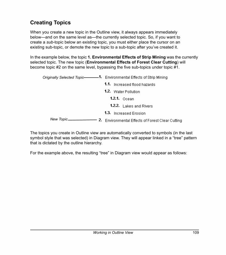
Creating Topics When you create a new topic in the Outline view, it always appears immediately below—and on the same level as—the currently selected topic. So, if you want to create a sub-topic below an existing topic, you must either place the cursor on an existing sub-topic, or demote the new topic to a sub-topic after you’ve created it.
In the example below, the topic 1. Environmental Effects of Strip Mining was the currently selected topic. The new topic (Environmental Effects of Forest Clear Cutting) will become topic #2 on the same level, bypassing the five sub-topics under topic #1.
The topics you create in Outline view are automatically converted to symbols (in the last symbol style that was selected) in Diagram view. They will appear linked in a “tree” pattern that is dictated by the outline hierarchy.
For the example above, the resulting “tree” in Diagram view would appear as follows:
Originally Selected Topic
New Topic
Working in Outline View 109
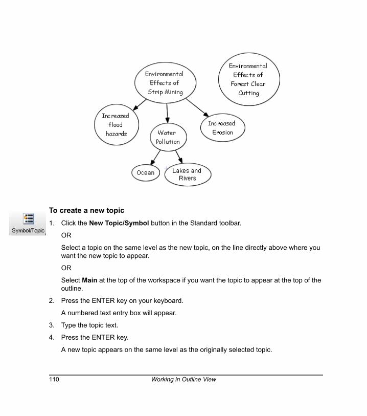
To create a new topic1. Click the New Topic/Symbol button in the Standard toolbar.
OR
Select a topic on the same level as the new topic, on the line directly above where you want the new topic to appear.
OR
Select Main at the top of the workspace if you want the topic to appear at the top of the outline.
2. Press the ENTER key on your keyboard.
A numbered text entry box will appear.
3. Type the topic text.
4. Press the ENTER key.
A new topic appears on the same level as the originally selected topic.
110 Working in Outline View
Creating Notes, Links and Sub-levelsYou can do almost everything in Outline view that you can do in Diagram view, and that includes creating topic sub-levels, links and adding notes to topics.
NOTE: Although you can’t create connectors in Outline view, you can view and edit connector text.
To add a note to a topic
1. Select the topic.
2. Click the Add Note button in the Formatting toolbar.
The selected topic will expand to include an empty line underneath the topic text.
3. Type your note in the empty line.
4. Click outside of the text box to commit the text.
A Note icon appears in the Icon Sidebar. Click the icon to view the note.
NOTE: To view the note without clicking the Note icon, select View > Notes > Show or Show All.
To add a link to a website, file or level 1. Select the topic.
2. Click the Add Link button in the Formatting toolbar.
The Insert Link dialog box appears.
3. Click website, file or level in Of Type.
4. Specify or browse to the destination.
5. Click OK.
A Link icon will appear in the Icon Sidebar. Click the icon to go directly to the link source.
To add a sub-level to a topic
1. Select the topic.
2. Select View > Go to > Inside.
A new workspace opens on the newly created sub-level.
Working in Outline View 111
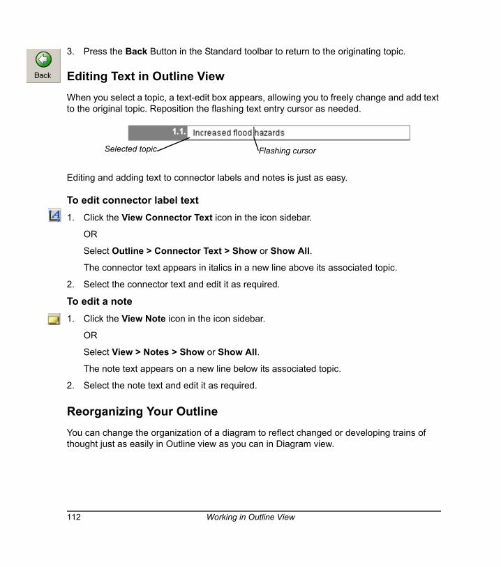
3. Press the Back Button in the Standard toolbar to return to the originating topic.
Editing Text in Outline ViewWhen you select a topic, a text-edit box appears, allowing you to freely change and add text to the original topic. Reposition the flashing text entry cursor as needed.
Editing and adding text to connector labels and notes is just as easy.
To edit connector label text1. Click the View Connector Text icon in the icon sidebar.
OR
Select Outline > Connector Text > Show or Show All.
The connector text appears in italics in a new line above its associated topic.
2. Select the connector text and edit it as required.
To edit a note1. Click the View Note icon in the icon sidebar.
OR
Select View > Notes > Show or Show All.
The note text appears on a new line below its associated topic.
2. Select the note text and edit it as required.
Reorganizing Your OutlineYou can change the organization of a diagram to reflect changed or developing trains of thought just as easily in Outline view as you can in Diagram view.
Selected topic Flashing cursor
112 Working in Outline View
You can click and drag a topic to move it up or down within the outline in its current level only. However, if you want to move a topic outside of its current level, either promoting or demoting it within the outline hierarchy, use the Promote and Demote buttons in the toolbar.
To alter the hierarchy of a diagram Click and drag the topic above or below its current location within its current level only.
OR
Click the Promote button to move the topic up one level.
OR
Click the Demote button to move the topic down one level.
To delete a topic (and its associated connector)
1. Select a symbol.
2. Click the Delete button in the Standard toolbar.
OR
Select Delete from the Edit or right-mouse menu.
OR
Press the DELETE key on your keyboard.
Hiding and Revealing Topics in Outline ViewJust like in Diagram view, you can work with all or selected topics displayed or keep sub-topics hidden from view.
For the sake of clarity, you may want to hide sub-topics. This way, your students can focus on general concepts first, and then you can selectively reveal supporting details—but only when you’re ready to discuss them.
NOTE: If you save the file with hidden or shown sub-topics, the file will re-open in the identical state.
Working in Outline View 113
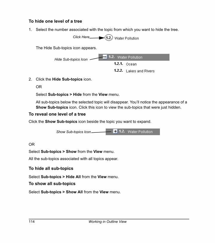
To hide one level of a tree
1. Select the number associated with the topic from which you want to hide the tree.
The Hide Sub-topics icon appears.
2. Click the Hide Sub-topics icon.
OR
Select Sub-topics > Hide from the View menu.
All sub-topics below the selected topic will disappear. You’ll notice the appearance of a Show Sub-topics icon. Click this icon to view the sub-topics that were just hidden.
To reveal one level of a treeClick the Show Sub-topics icon beside the topic you want to expand.
OR
Select Sub-topics > Show from the View menu.
All the sub-topics associated with all topics appear.
To hide all sub-topics
Select Sub-topics > Hide All from the View menu.
To show all sub-topics
Select Sub-topics > Show All from the View menu.
Click Here
Hide Sub-topics Icon
Show Sub-topics Icon
114 Working in Outline View
File Management
Managing SMART Ideas software project files (.ipr files) is very much like managing files in any other Windows application. For example, you can create a new file, save it for later viewing and revision, or print it. And, just like many familiar word processing applications, SMART Ideas software comes with many file templates to help get you started, and you can also create your own custom templates for those diagrams that you use often.
In addition to these standard file management tasks, you can export your files in many different formats so that people without SMART Ideas software can still see your work.
For example, you can export your diagram as a WordPerfect, Word, AppleWorks or plain text file. With Word and WordPerfect exports, you can choose to export both the Diagram and Outline view of your SMART Ideas file or both. However, the AppleWorks and plain text files you create are based on the text-only Outline view of your SMART Ideas file. You can also save your Diagram view as .jpeg, .png or .svg images. So, if you like, you can accompany a plain-text version of the Outline view with an image of the Diagram view in any of the three image formats.
You can also publish your SMART Ideas file onto the Web so that anyone with a Web browser can access your work.
Creating a New SMART Ideas FileWhen you create a new SMART Ideas file, you can use a template or start from a blank workspace.
To create a SMART Ideas file
1. Select New from the File menu.
The New SMART Ideas Diagram dialog box appears with Blank Diagram selected on the Documents tab.
2. To create a new template, select Blank Template.
OR
To base your new diagram on an existing or supplied template, click the Templates tab and select one of the templates from the list.
File Management 115

3. Click the Open button.
An untitled, blank workspace appears.
Opening a SMART Ideas FileIf you’re working in SMART Ideas software and want to open a recently used file, click the File menu. You’ll see the last four SMART Ideas software project files that you worked on at the bottom of the menu. Click any one of those files to instantly load it into the workspace.
To open a SMART Ideas file
1. Select Open from the File menu.
The Open dialog box appears.
2. Select an .ipr file.
3. Click the Open button.
Saving a SMART Ideas FileYou can save your file to your hard drive or a network location, as you would in any other program.
To save a SMART Ideas file
1. For a previously saved file, select Save from the File menu to save the file in the same format and with the same name, or click the Save button.
OR
Select Save As from the File menu to save the file with a different name or in a different location.
2. If you’re saving the file for the first time, enter a file name in the Save As dialog box and then click the Save button.
116 File Management
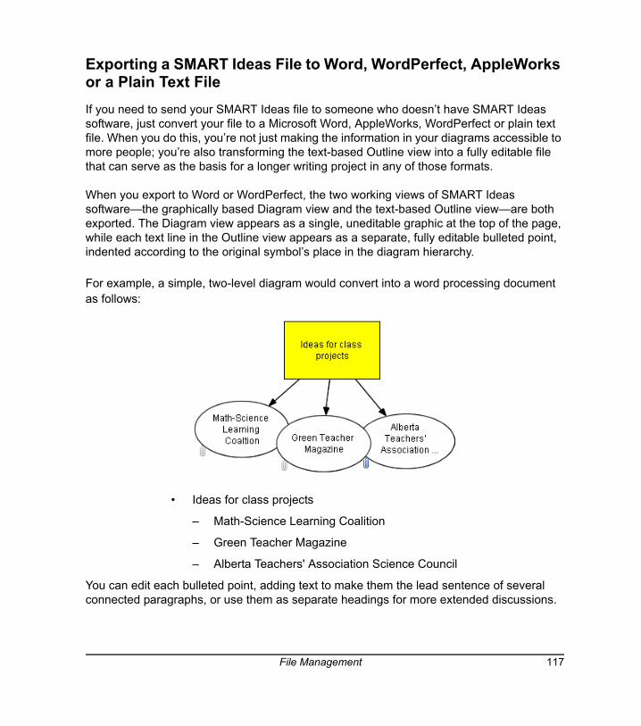
Exporting a SMART Ideas File to Word, WordPerfect, AppleWorks or a Plain Text FileIf you need to send your SMART Ideas file to someone who doesn’t have SMART Ideas software, just convert your file to a Microsoft Word, AppleWorks, WordPerfect or plain text file. When you do this, you’re not just making the information in your diagrams accessible to more people; you’re also transforming the text-based Outline view into a fully editable file that can serve as the basis for a longer writing project in any of those formats.
When you export to Word or WordPerfect, the two working views of SMART Ideas software—the graphically based Diagram view and the text-based Outline view—are both exported. The Diagram view appears as a single, uneditable graphic at the top of the page, while each text line in the Outline view appears as a separate, fully editable bulleted point, indented according to the original symbol’s place in the diagram hierarchy.
For example, a simple, two-level diagram would convert into a word processing document as follows:
• Ideas for class projects
– Math-Science Learning Coalition
– Green Teacher Magazine
– Alberta Teachers' Association Science Council
You can edit each bulleted point, adding text to make them the lead sentence of several connected paragraphs, or use them as separate headings for more extended discussions.
File Management 117
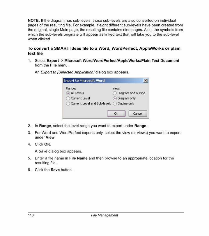
NOTE: If the diagram has sub-levels, those sub-levels are also converted on individual pages of the resulting file. For example, if eight different sub-levels have been created from the original, single Main page, the resulting file contains nine pages. Also, the symbols from which the sub-levels originate will appear as linked text that will take you to the sub-level when clicked.
To convert a SMART Ideas file to a Word, WordPerfect, AppleWorks or plain text file1. Select Export > MIcrosoft Word/WordPerfect/AppleWorks/Plain Text Document
from the File menu.
An Export to [Selected Application] dialog box appears.
2. In Range, select the level range you want to export under Range.
3. For Word and WordPerfect exports only, select the view (or views) you want to export under View.
4. Click OK.
A Save dialog box appears.
5. Enter a file name in File Name and then browse to an appropriate location for the resulting file.
6. Click the Save button.
118 File Management
Exporting Workspace Views to the WebIt’s easy to create diagrams and then publish on the Internet or send them to people who don’t have SMART Ideas software installed on their computers. You can save your diagrams in either a graphical (Diagram view) or text-only form (Outline view) that’s ready for Web publication.
To save your diagrams in graphical form for the Internet, use the Export Diagram View to Web command. This command saves your current diagram as a high-quality, Web-ready graphic and retains all hyperlinks in the document after conversion.
To save your diagrams to the Internet in text-only form, use the Export Outline View to Web (Text) command: This command converts the Outline view of your diagram into HTML format, ready for online publication.
To export the Diagram view for Web publication1. Select Export Diagram View to Web from the File menu.
A Saving message appears as your diagram is converted.
2. Wait a few moments.
The converted diagram opens in your Web browser.
To export the Outline view for Web publication1. Select Export Outline to Web (Text) from the File menu.
NOTE: You can be in Diagram view when you select this command. An HTML file of just the Outline view will be created.
2. Wait a few moments.
The converted text-only outline opens in your Web browser.
Printing a DiagramYou can print the current level of your diagram or the current level plus all associated sub-levels. If a diagram is too large to fit on a single page, SMART Ideas software tiles the diagram onto as many pages as necessary.
File Management 119
If you'd like to shrink the diagram to fit on a single page or change the way the diagram is tiled, use the Print Preview command. In Print Preview, you can also add headers and footers to your printed pages, which can be centered or aligned on the left or right side of the page.
To print a SMART Ideas file
1. From the File menu, select:
– Print Preview to see how your diagram will look on the printed page
– Print Current Level to print only the current level of your diagram
– Print All Levels to print every level of your diagram
The Print dialog box appears.
2. Specify the printer you want to use in the Name box.
3. Specify what you want printed in the Print range box.
4. Specify the number of copies you want printed in the Number of copies box.
5. Click OK.
Using Print Preview
In addition to using Print Preview to see how the diagram's levels look before you print them, this command also lets you:
• change how large diagrams tile to several pages
NOTE: When a level is too large to fit on a single printed page, SMART Ideas software tiles the diagram onto as many pages as necessary to accommodate the entire level. You can use Print Preview to change the way the level is divided into separate pages.
• click and drag the page boundary (horizontal or vertical) to print only a specific area of the page
• add a header or footer to a printed page
• print the current, selected or all levels
• shrink a large diagram to fit on a single page
120 File Management
To change how large diagrams tile to several pages1. Select Print Preview from the File menu.
The Print Preview view of the file appears.
2. In the Level Sorter on the left, click the thumbnail for the level that will be tiled.
The level appears in the preview area to the right. Dotted blue lines indicate where the page breaks will occur.
3. Adjust the page breaks by dragging the dotted lines anywhere you'd like.
NOTE: To restore the page breaks to their original positions, press the Reset button in the lower-right corner.
To shrink a large diagram to fit on a single page1. In the Level Sorter on the left, click the thumbnail for the level that will be tiled.
The level appears in the preview area to the right.
2. Press the Fit to Page button in the lower right of the preview area.
The diagram shrinks to occupy only a single page when printed.
NOTE: To restore the page to its original size, press the Reset button in the lower right.
To print pages from within Print Preview1. To print the level currently showing in the preview area, select Print current level from
the drop-down list.
OR
To print the selected levels, select Print selected levels from the drop-down list. (To select a level to print, click the box in the upper-right corner of a level's thumbnail to make a check-mark appear.)
OR
To print all the levels in a diagram, select Print all levels from the drop-down list.
OR
To print only part of the page, click and drag the page boundary (vertical or horizontal) to specify a portion of the page.
2. Click the Print button.
File Management 121
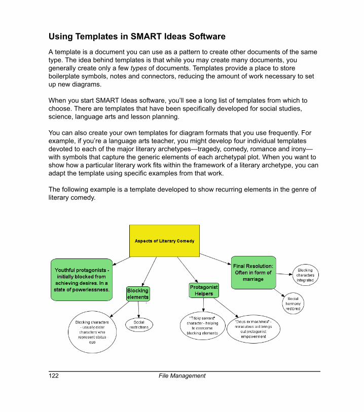
Using Templates in SMART Ideas SoftwareA template is a document you can use as a pattern to create other documents of the same type. The idea behind templates is that while you may create many documents, you generally create only a few types of documents. Templates provide a place to store boilerplate symbols, notes and connectors, reducing the amount of work necessary to set up new diagrams.
When you start SMART Ideas software, you’ll see a long list of templates from which to choose. There are templates that have been specifically developed for social studies, science, language arts and lesson planning.
You can also create your own templates for diagram formats that you use frequently. For example, if you’re a language arts teacher, you might develop four individual templates devoted to each of the major literary archetypes—tragedy, comedy, romance and irony— with symbols that capture the generic elements of each archetypal plot. When you want to show how a particular literary work fits within the framework of a literary archetype, you can adapt the template using specific examples from that work.
The following example is a template developed to show recurring elements in the genre of literary comedy.
122 File Management
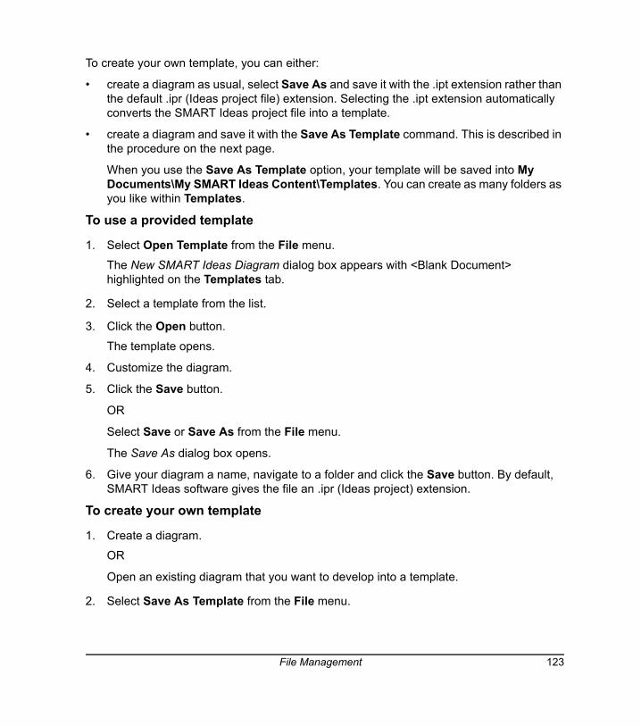
To create your own template, you can either:
• create a diagram as usual, select Save As and save it with the .ipt extension rather than the default .ipr (Ideas project file) extension. Selecting the .ipt extension automatically converts the SMART Ideas project file into a template.
• create a diagram and save it with the Save As Template command. This is described in the procedure on the next page.
When you use the Save As Template option, your template will be saved into My Documents\My SMART Ideas Content\Templates. You can create as many folders as you like within Templates.
To use a provided template
1. Select Open Template from the File menu.
The New SMART Ideas Diagram dialog box appears with <Blank Document> highlighted on the Templates tab.
2. Select a template from the list.
3. Click the Open button.
The template opens.
4. Customize the diagram.
5. Click the Save button.
OR
Select Save or Save As from the File menu.
The Save As dialog box opens.
6. Give your diagram a name, navigate to a folder and click the Save button. By default, SMART Ideas software gives the file an .ipr (Ideas project) extension.
To create your own template
1. Create a diagram.
OR
Open an existing diagram that you want to develop into a template.
2. Select Save As Template from the File menu.
File Management 123
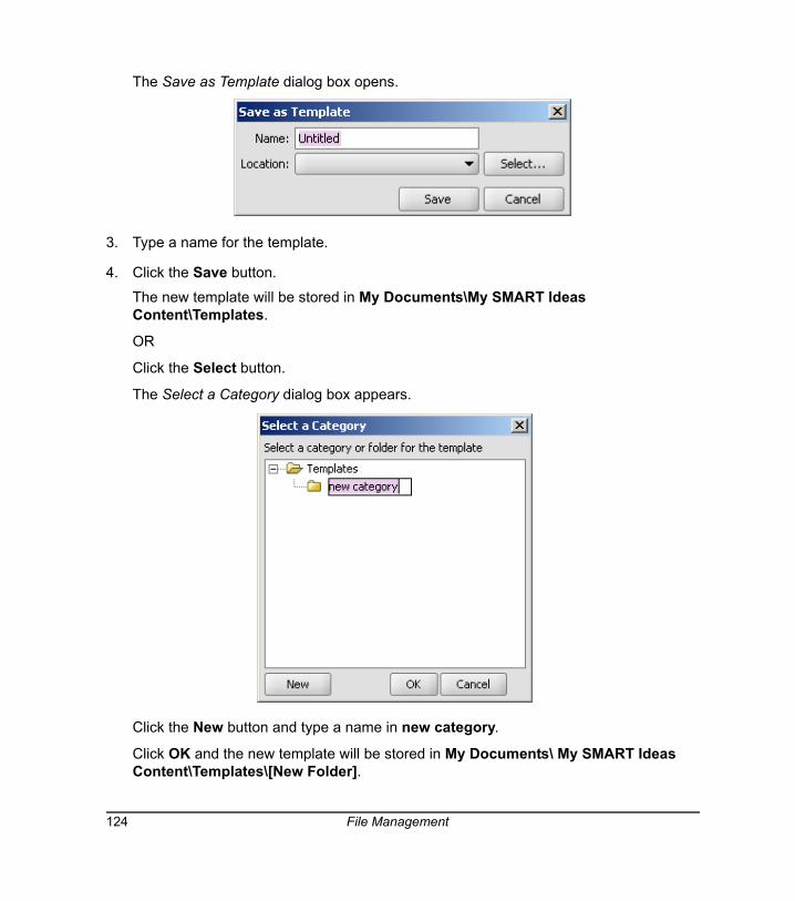
The Save as Template dialog box opens.
3. Type a name for the template.
4. Click the Save button.
The new template will be stored in My Documents\My SMART Ideas Content\Templates.
OR
Click the Select button.
The Select a Category dialog box appears.
Click the New button and type a name in new category.
Click OK and the new template will be stored in My Documents\ My SMART Ideas Content\Templates\[New Folder].
124 File Management

Using SMART Ideas Software on a SMART Board Interactive Whiteboard
Working on the SMART Board interactive whiteboard in your classroom is the best way to use SMART Ideas software. Pick up a pen tray pen and write in the SMART Ideas workspace. Then press a button to transform your handwritten annotation into typed text inside a symbol. This makes it easy to quickly create symbols that contain clear, typed text—without having to dash over to a keyboard.
Handwriting Recognition
The interactive whiteboard (when used with a projector) also provides an enlarged, bright image that’s ideal for presenting diagrams to your class. With the touch-sensitive interactive whiteboard, you can create and manipulate diagram objects right at the screen. Use your finger to move symbols, add links, open sub-levels and activate toolbar buttons. Use a pen tray pen to create symbols and connectors faster than you can with a keyboard or mouse. Then save everything that you do at the interactive whiteboard into the current .ipr file.
To summarize, after creating a hand-drawn annotation on the SMART Board interactive whiteboard with a pen tray pen, you can:
• transform it into a symbol with a typewritten label
• preserve it as a graphical symbol (if it’s a drawing)
Using SMART Ideas Software on a SMART Board Interactive Whiteboard 125
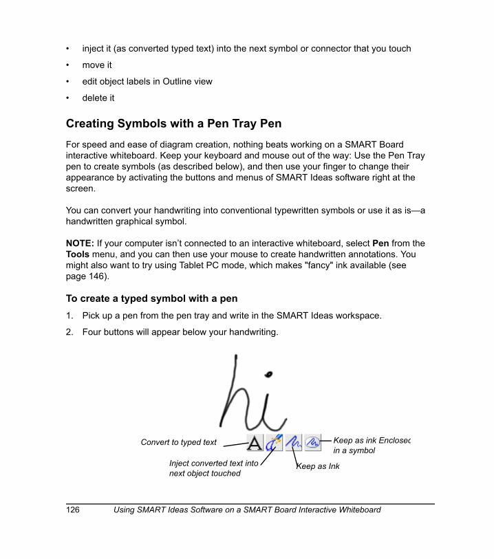
• inject it (as converted typed text) into the next symbol or connector that you touch
• move it
• edit object labels in Outline view
• delete it
Creating Symbols with a Pen Tray PenFor speed and ease of diagram creation, nothing beats working on a SMART Board interactive whiteboard. Keep your keyboard and mouse out of the way: Use the Pen Tray pen to create symbols (as described below), and then use your finger to change their appearance by activating the buttons and menus of SMART Ideas software right at the screen.
You can convert your handwriting into conventional typewritten symbols or use it as is—a handwritten graphical symbol.
NOTE: If your computer isn’t connected to an interactive whiteboard, select Pen from the Tools menu, and you can then use your mouse to create handwritten annotations. You might also want to try using Tablet PC mode, which makes "fancy" ink available (see page 146).
To create a typed symbol with a pen1. Pick up a pen from the pen tray and write in the SMART Ideas workspace.
2. Four buttons will appear below your handwriting.
Keep as ink Enclosedin a symbol
Keep as InkInject converted text into next object touched
Convert to typed text
126 Using SMART Ideas Software on a SMART Board Interactive Whiteboard
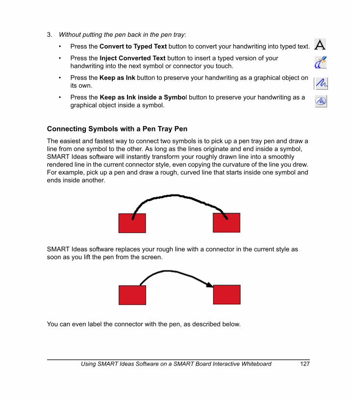
3. Without putting the pen back in the pen tray:
• Press the Convert to Typed Text button to convert your handwriting into typed text.
• Press the Inject Converted Text button to insert a typed version of your handwriting into the next symbol or connector you touch.
• Press the Keep as Ink button to preserve your handwriting as a graphical object on its own.
• Press the Keep as Ink inside a Symbol button to preserve your handwriting as a graphical object inside a symbol.
Connecting Symbols with a Pen Tray PenThe easiest and fastest way to connect two symbols is to pick up a pen tray pen and draw a line from one symbol to the other. As long as the lines originate and end inside a symbol, SMART Ideas software will instantly transform your roughly drawn line into a smoothly rendered line in the current connector style, even copying the curvature of the line you drew. For example, pick up a pen and draw a rough, curved line that starts inside one symbol and ends inside another.
SMART Ideas software replaces your rough line with a connector in the current style as soon as you lift the pen from the screen.
You can even label the connector with the pen, as described below.
Using SMART Ideas Software on a SMART Board Interactive Whiteboard 127
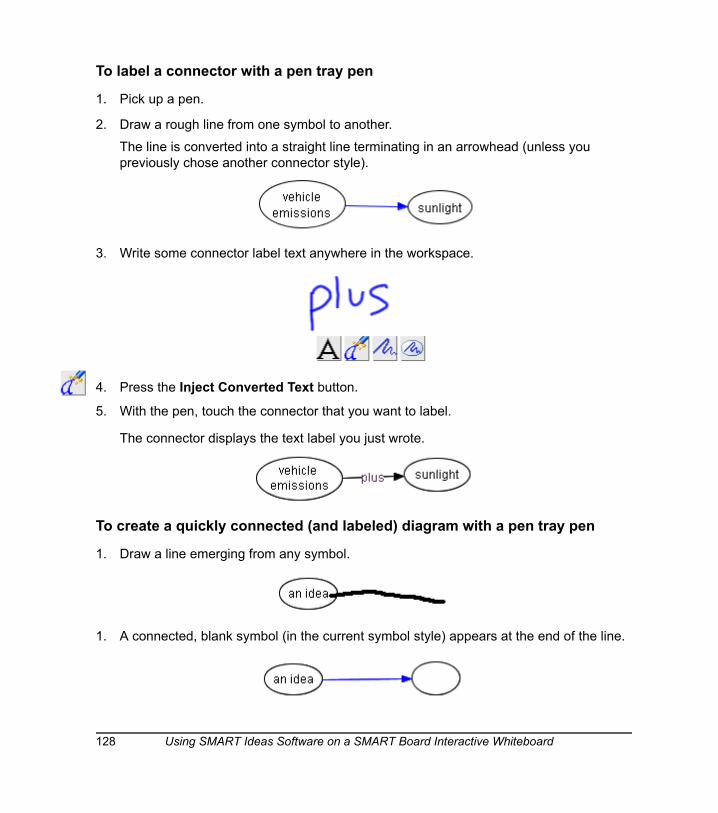
To label a connector with a pen tray pen
1. Pick up a pen.
2. Draw a rough line from one symbol to another.
The line is converted into a straight line terminating in an arrowhead (unless you previously chose another connector style).
3. Write some connector label text anywhere in the workspace.
4. Press the Inject Converted Text button.
5. With the pen, touch the connector that you want to label.
The connector displays the text label you just wrote.
To create a quickly connected (and labeled) diagram with a pen tray pen
1. Draw a line emerging from any symbol.
1. A connected, blank symbol (in the current symbol style) appears at the end of the line.
128 Using SMART Ideas Software on a SMART Board Interactive Whiteboard
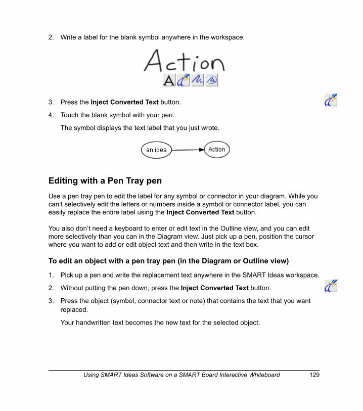
2. Write a label for the blank symbol anywhere in the workspace.
3. Press the Inject Converted Text button.
4. Touch the blank symbol with your pen.
The symbol displays the text label that you just wrote.
Editing with a Pen Tray pen Use a pen tray pen to edit the label for any symbol or connector in your diagram. While you can’t selectively edit the letters or numbers inside a symbol or connector label, you can easily replace the entire label using the Inject Converted Text button.
You also don’t need a keyboard to enter or edit text in the Outline view, and you can edit more selectively than you can in the Diagram view. Just pick up a pen, position the cursor where you want to add or edit object text and then write in the text box.
To edit an object with a pen tray pen (in the Diagram or Outline view)
1. Pick up a pen and write the replacement text anywhere in the SMART Ideas workspace.
2. Without putting the pen down, press the Inject Converted Text button.
3. Press the object (symbol, connector text or note) that contains the text that you want replaced.
Your handwritten text becomes the new text for the selected object.
Using SMART Ideas Software on a SMART Board Interactive Whiteboard 129

130 Using SMART Ideas Software on a SMART Board Interactive Whiteboard

Customer Support
SMART’s Technical Support team welcomes your call. However, you may first want to contact your local reseller if you experience any difficulty with SMART Ideas software, as they may be able to solve the problem without delay.
All SMART products include free telephone, fax and e-mail support.
Telephone: 1.866.518.6791 (toll-free in Canada/U.S) or +1.403.228.5940 (all other countries)
(Available 7 a.m. − 6 p.m. Mountain time from Monday to Friday)
Fax: +1.403.806.1256
E-mail: [email protected]
Web Site: www.smarttech.com/supportThe support representative may ask you for the version of the software that’s causing the problem and the version of your computer’s operating system.
General Inquiries
Main Switchboard: 1.888.42.SMART (toll-free in Canada/U.S.) or +1.403.245.0333 (all other countries)
Fax: +1.403.228.2500
E-mail: [email protected]
Address:SMART Technologies Inc.
1207 – 11th Avenue SW, Suite 300
Calgary, AB
CANADA T2R 1K9
RegistrationA User Registration card was included with SMART Ideas software. To help us serve you, fill in and mail this card to SMART Technologies Inc. or register online at www.smarttech.com/registration.
Customer Support 131

132 Customer Support
Appendix A: Using SMART Ideas Server Software
If you’re working with SMART Ideas server software, you can share your SMART Ideas file online and collaborate in real time with other users. And, since SMART Ideas server software works in conjunction with a Web server, your team can be located in the same office or all over the world. You can not only create and manipulate objects collaboratively, you can use the Chat feature to write text messages at the same time.
When you’re working online, your file is simply known as a project. Although a project is accessible to other server users, many security features are available to protect sensitive information. You can specify who can access your project, and even which symbols you want other team members to view or edit.
Users can work in the same or different areas (or levels) of a project without interrupting the work of others. However, if you’re conferencing with other users, you may want the group to follow along as you navigate to different project areas and sub-levels. SMART Ideas software has an easy-to-use Follow Me feature that’s ideal for this purpose. Of course, if you prefer to work on a diagram privately, you can work from your hard drive, and then upload the project to the server when you’re ready to share it.
As changes are made, projects are updated instantly on the SMART Ideas software server, so changes are immediately visible to all users. But you aren’t restricted to viewing what other users are doing in real time: You can also view changes to the project that occurred after you logged off.
With SMART Ideas server software, you can:
• Configure security features (page 134)
• Connect to the server (page 135)
• Open a project (page 135)
• Create a project (page 136)
• Upload and download projects to the server (page 137)
• Restrict access to projects and objects within projects (page 138)
• Share your view with others (page 139)
• Chat with other project users (page 139)
Appendix A: Using SMART Ideas Server Software 133
• Receive e-mail notification of newly joined project members and project changes (page 142)
• Delete a project (page 143)
• Disconnect from the server (page 144)
Server Security OverviewSMART Ideas server software offers a secure online environment for even the most sensitive project material. All security is based on your network login name and password. When your user identification has been established, SMART Ideas server software determines if your level of access is appropriate for the task you want to perform.
There are four user categories for SMART Ideas server software:
AdministratorsAdministrators maintain and have full access to all SMART Ideas server software files. Administrators can create guest accounts and limit which users can be designated as project owners.
OwnersIf you create a project, you are the owner of that project. You can add and delete users, grant co-owner status to selected users and delete the project from the server.
UsersA user is anyone who is logged on to the SMART Ideas server software. Users can open only those projects to which they’ve been granted access, but they have both read and write privileges to these projects. Those users without access will not see that project title listed in the Project Manager.
GuestsGuests have neither an individual login name nor a password. An administrator must set up a general guest account for temporary use. Once logged in, guests have the same read and write privileges as any other user.
134 Appendix A: Using SMART Ideas Server Software
Connecting to the ServerTo share your diagrams with other users, you must first connect to SMART Ideas server software.
To connect to SMART Ideas server software
1. Select Tools > Online > Go Online.
The Connect to Server dialog box appears.
2. Enter the server URL address in Location (URL). If unknown, contact your SMART Ideas Software Administrator for the correct address.
3. Enter the same User name and Password that you use to sign on to your network.
4. Click the Connect button.
The Project Manager dialog box appears, with a list of all the SMART Ideas software projects that you can access on this server.
Opening a ProjectThe Project Manager displays a list of all those projects that you either own or have permission to access. If the project you want to open is located on a different server, you’ll need to disconnect from the current server and then connect to the other server.
To open a project
1. Connect to the server (see the previous procedure).
OR
If you're already connected the server, select Tools > Online > Open Project.
The Project Manager dialog box appears.
2. Select a project from the project list.
3. Click the Open button.
Appendix A: Using SMART Ideas Server Software 135
Creating a ProjectWhen you’re connected to SMART Ideas server software, you can create a project on the server or upload an existing SMART Ideas file from your hard drive.
To create a project
1. Open the Project Manager, either by connecting to the server (see page 135) or by selecting Tools > Online > Open Project.
The Project Manager dialog box appears.
2. Click the New button.
A Create New Project dialog appears.
3. Enter a name for the new project.
4. Click OK.
A new, blank SMART Ideas workspace appears. The project name will also appear in the project list of your Project Manager.
5. Select the users with whom you want to share the new project (see page 138).
To upload a SMART Ideas diagram as a new project
1. Select Tools > Online > Upload New Project.
The Open dialog box appears.
2. Browse to the .ipr file that you want to upload and select it.
3. Click the Open button.
An Uploading Project message appears. This process may take a few moments. Another message informs you when the project is available online.
4. Click the Close button.
The uploaded project appears.
5. Select the users with whom you want to share the new project (see page 138).
136 Appendix A: Using SMART Ideas Server Software
Downloading a Project to Your Hard Drive/Uploading Back to the ServerAfter working on a project on a server, you may want to continue developing your ideas from a local hard drive. Or you may be on the road with your laptop and want to work on a project while you’re away.
It’s easy to download a project, work on it as an offline .ipr file and then upload it to the server, merging the original project with your revision. Any changes you made to the offline file will appear in the project after the merge.
To download a project to your hard drive
1. When online, select Save As from the File menu.
The Save As dialog box appears.
2. Select your hard drive in the Save in box.
3. Enter a name in the File name box.
4. Click the Save button.
The newly created .ipr file is now available to use offline.
To merge a previously downloaded project
1. Connect to the server and open the project into which you want to merge your SMART Ideas file.
2. Upload the .ipr file to the server (see page 136).
3. Select Tools > Online > Upload New Project.
The Open dialog box appears.
4. Browse to the project that you want to merge with the current project and select it.
5. Click the Open button.
Your changes are added to the server-resident project.
Appendix A: Using SMART Ideas Server Software 137
Controlling Project AccessIf you create a project, you are the project owner, and, as such, you control access to the project. When you create a new project in SMART Ideas server software, or at any time in the life of a project you own, you may want to restrict or expand access to it. You can also allow unlimited user access to your project.
To expand access to your project
1. Select Tools > Online > Project Administration.
The Project Administration dialog box opens with a list of all projects on the server.
2. Scroll to the project, select it, and click the Properties button.
NOTE: If you aren’t the owner of the selected project, the Properties button is grayed out (inactive).
The Project dialog box opens with a list of all available SMART Ideas software server users.
3. To add a user, click the Users tab, select a user's ID from the list, and click the Add button.
OR
To add all available users, select Make this project visible to all users.
OR
To add an owner, click the Owners tab, select a user's ID from the list, and click the Add button.
NOTE: If you make a user a co-owner, that person can add and remove users from the Users tab, and delete the project from the server.
4. Click OK.
To remove access to your project
1. Select Tools > Online > Project Administration.
The Project Administration dialog box opens.
2. Scroll to the project, select it, and click the Properties button.
The Project dialog box opens.
138 Appendix A: Using SMART Ideas Server Software
3. To remove access for a project owner, select the Owners tab.
4. Select a user’s ID from the list.
5. Click the Remove button.
6. Click OK.
Sharing Your View with Other Project MembersKeep up with your collaboration partners working on online projects by ensuring you’re always sharing the same view. Use the Follow Me command to keep everyone focused on the same area of the project.
With the Follow Me feature is activated, the user with mouse control is the temporary project leader, and the view for all other project members will change to correspond to the leader’s view. If the leader opens a symbol sub-level, for example, this same sub-level becomes the current view for all other project members.
To share your view with others
1. Go online and open the same project as the rest of your group.
2. Select Tools > Online > Follow Me.
3. Ensure other group members also select Tools > Online > Follow Me.
Any group member who assumes mouse control determines the current view for the entire group.
Chatting with Other Project MembersTrue collaboration means actively communicating with others while you’re working on a project. The Chat command lets you collaborate fully: When you’re online you can send and receive messages privately with individual project members or with the entire group.
You can keep the lines of communication open throughout your group session. The Chat dialog box can stay on top, even when you move to symbol sub-levels.
To chat with all project members
1. Select Tools > Online > Chat.
Appendix A: Using SMART Ideas Server Software 139
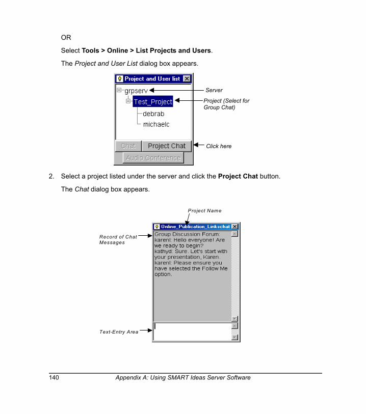
OR
Select Tools > Online > List Projects and Users.
The Project and User List dialog box appears.
2. Select a project listed under the server and click the Project Chat button.
The Chat dialog box appears.
Server
Project (Select forGroup Chat)
Click here
Project Name
Record of ChatMessages
Text-Entry Area
140 Appendix A: Using SMART Ideas Server Software
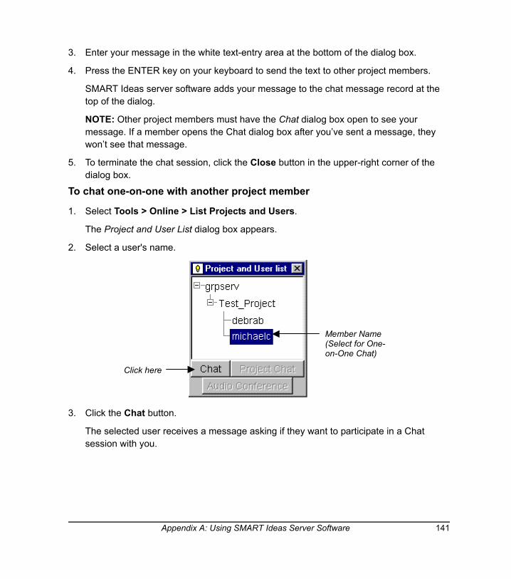
3. Enter your message in the white text-entry area at the bottom of the dialog box.
4. Press the ENTER key on your keyboard to send the text to other project members.
SMART Ideas server software adds your message to the chat message record at the top of the dialog.
NOTE: Other project members must have the Chat dialog box open to see your message. If a member opens the Chat dialog box after you’ve sent a message, they won’t see that message.
5. To terminate the chat session, click the Close button in the upper-right corner of the dialog box.
To chat one-on-one with another project member
1. Select Tools > Online > List Projects and Users.
The Project and User List dialog box appears.
2. Select a user's name.
3. Click the Chat button.
The selected user receives a message asking if they want to participate in a Chat session with you.
Member Name(Select for One-on-One Chat)
Click here
Appendix A: Using SMART Ideas Server Software 141
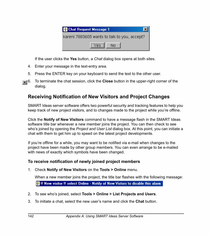
If the user clicks the Yes button, a Chat dialog box opens at both sites.
4. Enter your message in the text-entry area.
5. Press the ENTER key on your keyboard to send the text to the other user.
6. To terminate the chat session, click the Close button in the upper-right corner of the dialog.
Receiving Notification of New Visitors and Project Changes SMART Ideas server software offers two powerful security and tracking features to help you keep track of new project visitors, and to changes made to the project while you’re offline.
Click the Notify of New Visitors command to have a message flash in the SMART Ideas software title bar whenever a new member joins the project. You can then check to see who’s joined by opening the Project and User List dialog box. At this point, you can initiate a chat with them to get him up to speed on the latest project developments.
If you’re offline for a while, you may want to be notified via e-mail when changes to the project have been made by other group members. You can even arrange to be e-mailed with news of exactly which symbols have been changed.
To receive notification of newly joined project members
1. Check Notify of New Visitors on the Tools > Online menu.
When a new member joins the project, the title bar flashes with the following message:
2. To see who’s joined, select Tools > Online > List Projects and Users.
3. To initiate a chat, select the new user’s name and click the Chat button.
142 Appendix A: Using SMART Ideas Server Software
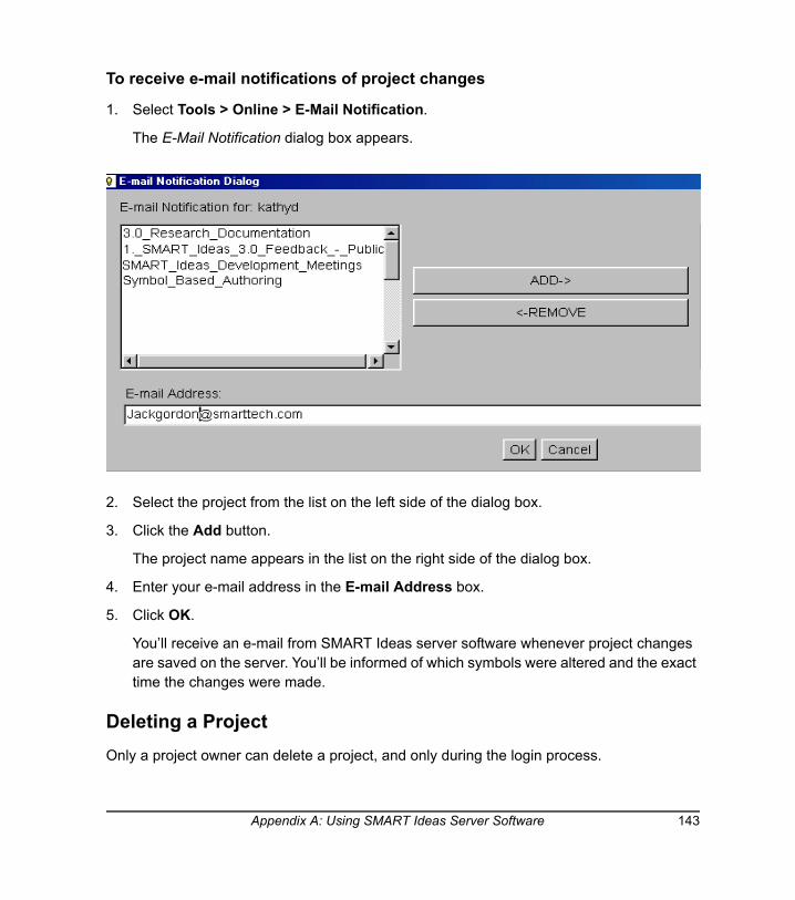
To receive e-mail notifications of project changes
1. Select Tools > Online > E-Mail Notification.
The E-Mail Notification dialog box appears.
2. Select the project from the list on the left side of the dialog box.
3. Click the Add button.
The project name appears in the list on the right side of the dialog box.
4. Enter your e-mail address in the E-mail Address box.
5. Click OK.
You’ll receive an e-mail from SMART Ideas server software whenever project changes are saved on the server. You’ll be informed of which symbols were altered and the exact time the changes were made.
Deleting a ProjectOnly a project owner can delete a project, and only during the login process.
Appendix A: Using SMART Ideas Server Software 143
1. Select Tools > Online > Go Online.
The Connect to Server dialog box appears.
2. Enter the server address in Location (URL).
OR
Select the server from the list.
3. Enter the same User name and Password that you use to sign on to the network.
4. Click the Connect button.
The Project Manager dialog box appears.
5. Select the project you want to delete.
6. Click the Delete button.
A confirmation box appears.
7. Click Yes.
Disconnecting from the ServerWhen online, select Tools > Online > Go Offline to disconnect from the server.
SMART Ideas software remains open in stand-alone mode.
To reconnect to the server, select Tools > Online > Go Online. If you reconnect during the current SMART Ideas software session, the server remembers your user name and password, so you only need to click the Connect button in the Connect to Server dialog box.
144 Appendix A: Using SMART Ideas Server Software

Appendix B: Using SMART Ideas Software on a Tablet PC
When used on a Tablet PC, SMART Ideas software does everything described in this guide —and more. While this appendix focuses on those aspects of SMART Ideas software that have been developed for Tablet PC owners, you should also read the other sections of this guide to become familiar with all the features offered by this versatile concept-mapping software.
When you open SMART Ideas software on a Tablet PC, you’ll see the following four buttons in the toolbar, just above the center of the workspace.
NOTE: These buttons are also available to all other users of SMART Ideas software. Select Tools > Customize > Tablet Mode, and then select Enable tablet mode. Now the tools described in this section are available to anyone with SMART Ideas software.
Use these buttons to create, edit and manipulate SMART Ideas objects with your tablet pen.
More specifically, you can use your tablet pen to:
• write and draw in a variety of ink colors, widths and shapes (page 146)
• convert ink into typed text (inside a symbol) using handwriting recognition (page 146)
• transform shapes you draw with the tablet pen into perfect squares or circles (page 149). These shapes become SMART Ideas symbols.
• select individual or multiple objects (page 150)
• group and ungroup writing and drawing objects (page 151)
Pen Settings
Pen Tool Lasso Selection Tool
Eraser Tool
Appendix B: Using SMART Ideas Software on a Tablet PC 145
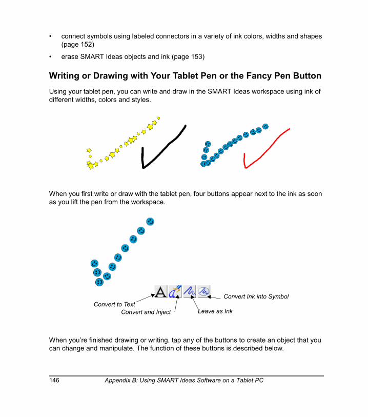
• connect symbols using labeled connectors in a variety of ink colors, widths and shapes (page 152)
• erase SMART Ideas objects and ink (page 153)
Writing or Drawing with Your Tablet Pen or the Fancy Pen ButtonUsing your tablet pen, you can write and draw in the SMART Ideas workspace using ink of different widths, colors and styles.
When you first write or draw with the tablet pen, four buttons appear next to the ink as soon as you lift the pen from the workspace.
When you’re finished drawing or writing, tap any of the buttons to create an object that you can change and manipulate. The function of these buttons is described below.
Convert to TextLeave as InkConvert and Inject
Convert Ink into Symbol
146 Appendix B: Using SMART Ideas Software on a Tablet PC
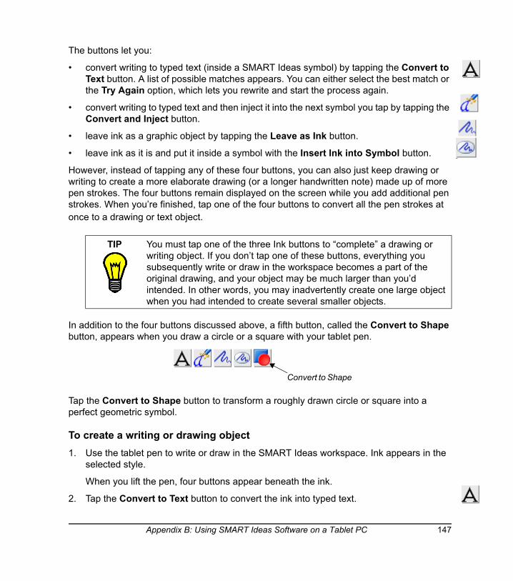
The buttons let you:
• convert writing to typed text (inside a SMART Ideas symbol) by tapping the Convert to Text button. A list of possible matches appears. You can either select the best match or the Try Again option, which lets you rewrite and start the process again.
• convert writing to typed text and then inject it into the next symbol you tap by tapping the Convert and Inject button.
• leave ink as a graphic object by tapping the Leave as Ink button.
• leave ink as it is and put it inside a symbol with the Insert Ink into Symbol button.
However, instead of tapping any of these four buttons, you can also just keep drawing or writing to create a more elaborate drawing (or a longer handwritten note) made up of more pen strokes. The four buttons remain displayed on the screen while you add additional pen strokes. When you’re finished, tap one of the four buttons to convert all the pen strokes at once to a drawing or text object.
In addition to the four buttons discussed above, a fifth button, called the Convert to Shape button, appears when you draw a circle or a square with your tablet pen.
Tap the Convert to Shape button to transform a roughly drawn circle or square into a perfect geometric symbol.
To create a writing or drawing object1. Use the tablet pen to write or draw in the SMART Ideas workspace. Ink appears in the
selected style.
When you lift the pen, four buttons appear beneath the ink.
2. Tap the Convert to Text button to convert the ink into typed text.
TIP You must tap one of the three Ink buttons to “complete” a drawing or writing object. If you don’t tap one of these buttons, everything you subsequently write or draw in the workspace becomes a part of the original drawing, and your object may be much larger than you’d intended. In other words, you may inadvertently create one large object when you had intended to create several smaller objects.
Convert to Shape
Appendix B: Using SMART Ideas Software on a Tablet PC 147
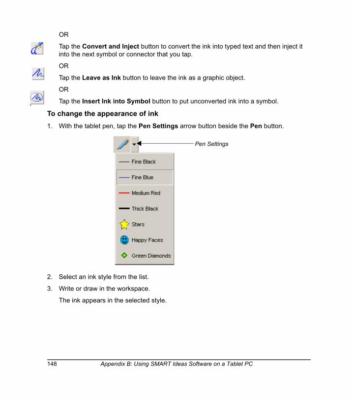
OR
Tap the Convert and Inject button to convert the ink into typed text and then inject it into the next symbol or connector that you tap.
OR
Tap the Leave as Ink button to leave the ink as a graphic object.
OR
Tap the Insert Ink into Symbol button to put unconverted ink into a symbol.
To change the appearance of ink1. With the tablet pen, tap the Pen Settings arrow button beside the Pen button.
2. Select an ink style from the list.
3. Write or draw in the workspace.
The ink appears in the selected style.
Pen Settings
148 Appendix B: Using SMART Ideas Software on a Tablet PC
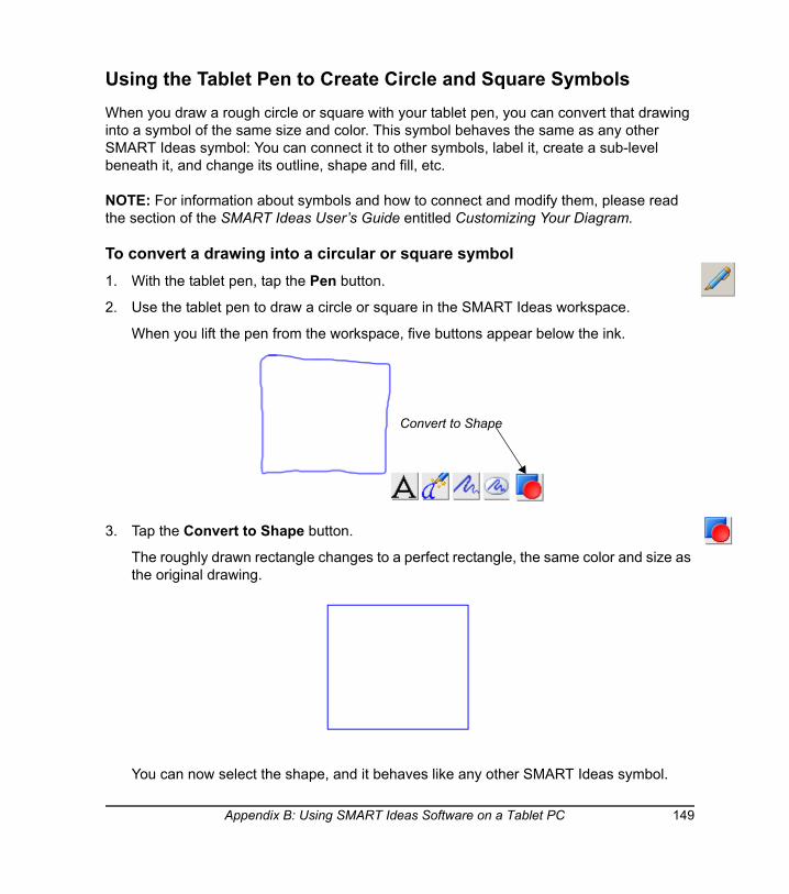
Using the Tablet Pen to Create Circle and Square SymbolsWhen you draw a rough circle or square with your tablet pen, you can convert that drawing into a symbol of the same size and color. This symbol behaves the same as any other SMART Ideas symbol: You can connect it to other symbols, label it, create a sub-level beneath it, and change its outline, shape and fill, etc.
NOTE: For information about symbols and how to connect and modify them, please read the section of the SMART Ideas User’s Guide entitled Customizing Your Diagram.
To convert a drawing into a circular or square symbol1. With the tablet pen, tap the Pen button.
2. Use the tablet pen to draw a circle or square in the SMART Ideas workspace.
When you lift the pen from the workspace, five buttons appear below the ink.
3. Tap the Convert to Shape button.
The roughly drawn rectangle changes to a perfect rectangle, the same color and size as the original drawing.
You can now select the shape, and it behaves like any other SMART Ideas symbol.
Convert to Shape
Appendix B: Using SMART Ideas Software on a Tablet PC 149

Selecting Objects with Your Tablet PenYou can select a single object by tapping the Lasso Selection button in the toolbar, and then either tap the object or roughly circle it with the tablet pen. However, the only way to select several objects is to circle them with the pen. You don’t need to be precise when you use the “lasso” selection technique: You need to surround only about sixty percent of the object or objects to make your selection.
To select a single object 1. Tap the Lasso Selection button in the toolbar.
2. Tap the object once with the tablet pen.
OR
Circle the object with the tablet pen.
The object appears enclosed by a selection rectangle.
To select several objects1. Tap the Lasso Selection button in the toolbar.
2. Roughly encircle the objects you want to select.
NOTE: Only about sixty percent of the objects need to be encircled. In addition, you don’t need to complete the circle for the selection to take place.
Grouping and Ungrouping InkWhen you finish a drawing and press the Leave as Ink button, each pen stroke in the drawing is automatically grouped as a unit with all the other pen strokes. The pen strokes function as a unit, and you can perform any action (such as resizing or changing line width or color) on the entire group.
TIP Tapping an object to select it works best with symbols or connectors. It’s more difficult to select unconverted ink drawing and writing in this manner because you must be very careful to tap precisely on a drawing line (which can be quite fine). For this reason, you should use the “lasso” selection technique and circle drawing and writing objects with your pen.
150 Appendix B: Using SMART Ideas Software on a Tablet PC
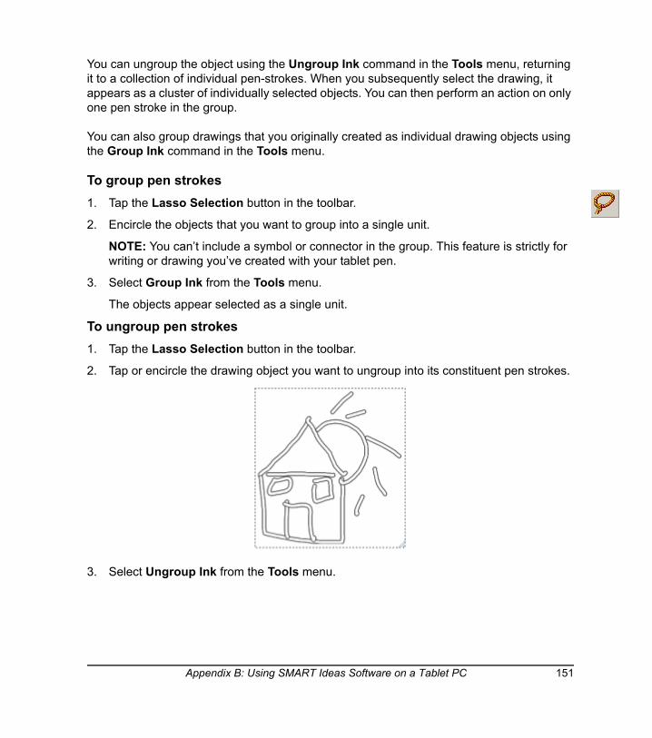
You can ungroup the object using the Ungroup Ink command in the Tools menu, returning it to a collection of individual pen-strokes. When you subsequently select the drawing, it appears as a cluster of individually selected objects. You can then perform an action on only one pen stroke in the group.
You can also group drawings that you originally created as individual drawing objects using the Group Ink command in the Tools menu.
To group pen strokes1. Tap the Lasso Selection button in the toolbar.
2. Encircle the objects that you want to group into a single unit.
NOTE: You can’t include a symbol or connector in the group. This feature is strictly for writing or drawing you’ve created with your tablet pen.
3. Select Group Ink from the Tools menu.
The objects appear selected as a single unit.
To ungroup pen strokes1. Tap the Lasso Selection button in the toolbar.
2. Tap or encircle the drawing object you want to ungroup into its constituent pen strokes.
3. Select Ungroup Ink from the Tools menu.
Appendix B: Using SMART Ideas Software on a Tablet PC 151
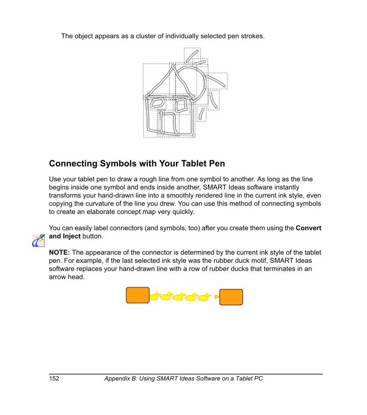
The object appears as a cluster of individually selected pen strokes.
Connecting Symbols with Your Tablet PenUse your tablet pen to draw a rough line from one symbol to another. As long as the line begins inside one symbol and ends inside another, SMART Ideas software instantly transforms your hand-drawn line into a smoothly rendered line in the current ink style, even copying the curvature of the line you drew. You can use this method of connecting symbols to create an elaborate concept map very quickly.
You can easily label connectors (and symbols, too) after you create them using the Convert and Inject button.
NOTE: The appearance of the connector is determined by the current ink style of the tablet pen. For example, if the last selected ink style was the rubber duck motif, SMART Ideas software replaces your hand-drawn line with a row of rubber ducks that terminates in an arrow head.
152 Appendix B: Using SMART Ideas Software on a Tablet PC
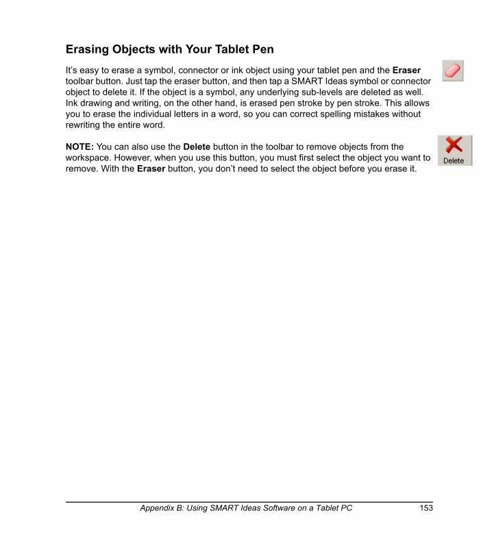
Erasing Objects with Your Tablet PenIt’s easy to erase a symbol, connector or ink object using your tablet pen and the Eraser toolbar button. Just tap the eraser button, and then tap a SMART Ideas symbol or connector object to delete it. If the object is a symbol, any underlying sub-levels are deleted as well. Ink drawing and writing, on the other hand, is erased pen stroke by pen stroke. This allows you to erase the individual letters in a word, so you can correct spelling mistakes without rewriting the entire word.
NOTE: You can also use the Delete button in the toolbar to remove objects from the workspace. However, when you use this button, you must first select the object you want to remove. With the Eraser button, you don’t need to select the object before you erase it.
Appendix B: Using SMART Ideas Software on a Tablet PC 153

154 Appendix B: Using SMART Ideas Software on a Tablet PC

Appendix C: License Agreement
Please read this License Agreement (“Agreement”) carefully. This is a legal agreement between you (the "Licensee") and SMART Technologies Inc. ("SMART") for SMART Ideas concept-mapping software and accompanying documentation (collectively, the "Software").
This Agreement provides important information concerning the Software, provides Licensee with a non-exclusive and non-transferable license to install and use the Software and contains warranty and liability information. By first installing and using the Software, you, on behalf of Licensee, are accepting the Software and agreeing to become bound by the terms of this Agreement. By so installing and using, you acknowledge that you have the authority to bind Licensee to the terms of this Agreement. If you do not have such authority or you, on behalf of Licensee, do not otherwise agree to be bound by the terms of this Agreement, do not install or use the Software.
1. Grant of LicenseSubject to payment of the applicable license fees, SMART grants Licensee a non-exclusive, non-transferable license to install and use the Software and accompanying documentation as follows:
Licensee may install and use the Software on that number of desktop computers recorded on the Sales Order Confirmation that is sent by electronic means to Licensee on account of (i) original purchase; or (ii) purchase of additional Software licenses, as the case may be;
Licensee may transfer the Software to another desktop computer provided that it is removed from the desktop computer from which it is transferred;
if Licensee is an educational institution, its teaching and academic staff may each make one (1) copy of the Software on their own personal computers for purposes directly related to their teaching and academic duties at the educational institution;
any copying of the Software is prohibited unless in accordance with Section 1(c) of this Agreement or unless for back-up or archival purposes in which case one(1) copy may be made; and
Licensee may copy the documentation, without change, as necessary to fully utilize the Software, provided the copies contain all the original proprietary notices.
Appendix C: License Agreement 155
Any attempt by Licensee to install or use the Software on desktop computers in excess of the number actually purchased and licensed by Licensee is a breach of this Agreement.
2.RestrictionsAll rights not expressly granted are reserved by SMART.
The Licensee must not:
• commercially distribute copies of the Software;
• modify, enhance, adapt, vary or create derivative works based on the Software;
• reverse engineer, reverse compile, disassemble, translate, decompile, disassemble or otherwise attempt to derive source code from (or the underlying ideas, algorithms, structure or organization of) the Software, for any purpose, including for the purpose of discovering any aspect of the technology inherent therein. Licensee may undertake such activities only to the extent that such activity is expressly and strictly permitted by applicable law notwithstanding the foregoing limitation, and then only for the purpose of achieving inter-operability of other independently developed computer programs;
• rent, lease, sublicense, distribute or supply the Software to any other party
The Licensee must:
• comply with all applicable laws regarding the use of the Software; and
• maintain all trademark and copyright notices on all copies of the Software.
3.Support ServicesSMART may provide Licensee with support services (“Support Services”) related to the Software in its discretion. Use of Support Services, if any, is governed by the SMART policies and programs described in the user guide, online documentation and/or other SMART-provided materials as modified by SMART from time to time. Any supplemental software provided to Licensee as part of Support Services shall be considered part of the Software and is subject to the terms of this Agreement.
156 Appendix C: License Agreement
4.Replacement, Modification and Upgrade of the SoftwareSMART reserves the right to replace, modify or upgrade the Software at any time by offering Licensee a replacement or modified version of the Software and to charge Licensee for such replacement, modification or upgrade. Any such replacement or modified Software or upgrade to the Software, or any component thereof, offered to Licensee by SMART shall be considered part of the Software and subject to the terms of this Agreement. In the event SMART offers a replacement or modified version of or upgrade to the Software (a) Licensee’s continued use of the Software is conditioned on Licensee’s acceptance of such replacement or modified version of or upgrade to the Software and any accompanying superceding end-user license agreement and (b) in the case of the replacement or modified Software, Licensee’s use of all prior versions of the Software is terminated.
5.TerminationWithout prejudice to any other rights, SMART may terminate this Agreement if Licensee fails to comply with the terms and conditions of this Agreement. In such event, Licensee must immediately stop using the Software, destroy all copies of the Software and all of its component parts, and upon request, provide an affidavit certifying Licensee’s compliance with the foregoing.
6.CopyrightAll right, title and copyright in and to the Software any copies thereof are owned by SMART or its suppliers. All title and intellectual property rights in and to the content which may be incorporated through use of the Software is the property of the respective content owner and may be protected by applicable copyright or other intellectual property laws and treaties. This Agreement grants Licensee no rights to use such content.
7.Export RestrictionsLicensee agrees that it will not export or re-export the Software, or any component thereof, or any process or service that is the direct product of the Software (the foregoing collectively referred to as the "Restricted Components") to any country, person or entity subject to Canadian or U.S. export restrictions.
Appendix C: License Agreement 157
Licensee specifically agrees not to export or re-export any of the Restricted Components (i) to any country to which Canada or the US has embargoed or restricted the export of goods or services or to any national of such country, wherever located, who intends to transmit or transport the Restricted Components back to such country (ii) to any person or entity who Licensee knows or has reason to know will utilize the Restricted Components in the design, development or production of nuclear, chemical or biological weapons, or (iii) to any person or entity who has been prohibited from participating in Canadian or US export transactions by any official body of the Canadian or US government. Licensee warrants and represents that no official of the Canadian or US government has suspended, revoked or denied its export privileges.
8.US Government Restricted RightsAll components of the Software provided to the U.S. government pursuant to solicitations issued on or after December 1, 1995 is provided with the commercial rights and restrictions described elsewhere herein. All components of the Software provided to the U.S. government pursuant to solicitations issued prior to December 1, 1995 is provided with Restricted Rights as provided for in FAR, 48 CFR 52.227-14 (June 1987) or DFAR's, 48 CFR 252.227-7013 (October 1988), as applicable.
9.NO WARRANTYANY USE OF THE SOFTWARE IS AT LICENSEE’S OWN RISK. TO THE MAXIMUM EXTENT PERMITTED BY APPLICABLE LAW, SMART AND ITS SUPPLIERS DISCLAIM ALL WARRANTIES AND CONDITIONS, EITHER EXPRESSED OR IMPLIED, INCLUDING, BUT NOT LIMITED TO, IMPLIED WARRANTIES OF MERCHANTABILITY, FITNESS FOR A PARTICULAR PURPOSE, TITLE AND NONINFRINGEMENT WITH REGARD TO THE SOFTARE, AND THE PROVISION OF OR FAILURE TO PROVIDE SUPPORT SERVICES. THIS LIMITED WARRANTY GIVES LICENSEE SPECIFIC LEGAL RIGHTS. LICENSEE MAY HAVE OTHERS, WHICH VARY FROM JURISDICTION TO JURISDICTION.
10.NO LIABILITY FOR CONSEQUENTIAL DAMAGES
TO THE MAXIMUM EXTENT PERMITTED BY APPLICABLE LAW, IN NO EVENT SHALL SMART OR ITS SUPPLIERS OR LICENSORS BE LIABLE FOR ANY SPECIAL, INCIDENTAL, INDIRECT, CONSEQUENTIAL OR PUNITIVE DAMAGES WHATSOEVER (INCLUDING, WITHOUT LIMITATION, DAMAGES FOR ANY INJURY TO ANY PERSON OR PROPERTY, DAMAGES FOR LOSS OF BUSINESS PROFITS, BUSINESS INTERRUPTION, LOSS OF BUSINESS INFORMATION, LOSS OF PRIVACY, DAMAGES FOR FAILURE TO MEET ANY DUTY INCLUDING THE DUTIES OF GOOD FAITH OR OF REASONABLE CARE, FOR NEGLIGENCE OR ANY OTHER
158 Appendix C: License Agreement

PECUNIARY LOSS) ARISING OUT OF THE USE OF OR INABILITY TO USE THE SOFTWARE OR THE PROVISION OF OR FAILURE TO PROVIDE SUPPORT SERVICES, WHETHER BASED ON CONTRACT, TORT, NEGLIGENCE, STRICT LIABILITY OR OTHERWISE, EVEN IF SMART OR ANY SUPPLIER OR LICENSOR OF SMART HAS BEEN ADVISED OF THE POSSIBILITY OF SUCH DAMAGES. BECAUSE SOME JURISDICTIONS DO NOT ALLOW THE EXCLUSION OR LIMITATION OF LIABILITY, THE ABOVE LIMITATION MAY NOT APPLY TO LICENSEE.
11.LIMITATION OF LIABILITYIN ANY CASE, SMART'S ENTIRE LIABILITY AND LICENSEE’S EXCLUSIVE REMEDY UNDER THIS AGREEMENT SHALL NOT EXCEED TEN DOLLARS (CAD $10.00).
12.SMART'S Suppliers and LicensorsAny release, disclaimer or limitation of SMART’s liability or damages pursuant to this Agreement shall be construed, in addition to SMART's benefit, also to the benefit of SMART's suppliers, licensors, employees and contractors, and without limiting any other defenses that such suppliers, licensors, employees and contractors may have, Licensee agrees to release such parties from liability or damages in accordance with such release, disclaimer or limitation of liability or damages to the same extent that such provisions apply to SMART.
13.ConfidentialityLicensee acknowledges that the Software embodies confidential information of SMART and/or its suppliers and licensors. To the extent Licensee has access to any such information, Licensee agrees to use such information only for the authorized use of the Software. Licensee further agree not to disclose such confidential information to any other party and to use at least the same degree of care to maintain the confidential nature of such information as Licensee uses to maintain the confidentiality of its own confidential information.
14.Injunctive ReliefLicensee acknowledges that, in the event Licensee breaches any provision of this Agreement, SMART will not have an adequate remedy in money or damages. SMART shall therefore be entitled to obtain an injunction against such breach from any court of competent jurisdiction immediately upon request without posting bond. SMART's right to obtain injunctive relief shall not limit its right to seek further remedies.
Appendix C: License Agreement 159

15.ModificationsNo modification of this Agreement shall be binding unless it is in writing and is signed by an authorized representative of the party against whom enforcement of the modification is sought.
16.Governing LawThis Agreement is governed by the laws of the Province of Alberta, Canada. Also to the extent permitted by applicable law, the parties irrevocably agree that any litigation involving this Agreement or the Software shall be brought in the provincial courts in the Province of Alberta or the federal courts of Canada, as the case may be. Licensee agrees that it shall not assert any claim that it is not subject to the jurisdiction of such courts, that the venue is improper, that the forum is inconvenient or any similar objection, claim or argument.
17.Entire AgreementThis Agreement constitutes the entire understanding and agreement of the parties and supercedes any and all prior or contemporaneous representations, understandings and agreements between the parties with respect of the subject matter of this Agreement. If any provision of this Agreement is held invalid, the remainder of this Agreement shall continue in full force and effect.
18.WaiverThe failure by a party to exercise any right hereunder shall not operate as a waiver of such party's right to exercise such right or any other right in the future.
QUESTIONSShould you have any questions concerning this Agreement, or if you desire to contact SMART for any reason, please write:
SMART Technologies Inc.
Suite 300, 1207-11th Avenue SW,
Calgary, AB Canada
T3C 0M5
SMART Ideas is a registered trademark of SMART Technologies Inc. in Canada and the U.S. SMART Ideas is a trademark of SMART Technologies Inc. in other jurisdictions.
160 Appendix C: License Agreement
Java(tm) Runtime EnvironmentVersion 1.1.6
Binary Code LicenseThis binary code license ("License") contains rights and restrictions associated with use of the Licenseeing Java Runtime Environment software and documentation ("Software"). Read the License carefully before using the Software. By using the Software you agree to the terms and conditions of this License.
1. License to Distribute. Licensee is granted a royalty-free right to reproduce and distribute the Software provided that Licensee:
(i) distributes the Software complete and unmodified (except for the specific files identified as optional in the Software README file), only as part of, and for the sole purpose of running, Licensee's Java compatible applet or application ("Program") into which the Software is incorporated;
(ii) does not distribute additional software intended to replace any component(s) of the Software;
(iii) agrees to incorporate the most current version of the Software that was available 180 days prior to each production release of the Program;
(iv) does not remove or alter any proprietary legends or notices contained in the Software;
(v) includes the provisions of Sections 2, 3, 5, 6, 8 and 9 in Licensee's license agreement for the Program; and
(vi) agrees to indemnify, hold harmless, and defend Sun and its licensors from and against any claims or lawsuits, including attorneys' fees, that arise or result from the use or distribution of the Program.
2. Java Platform Interface. Licensee may not modify the Java Platform Interface ("JPI", identified as classes contained within the "java" package or any subpackages of the "java" package), by creating additional classes within the JPI or otherwise causing the addition to or modification of the classes in the JPI. In the event that Licensee creates any Java-related API and distributes such API to others for applet or application development, Licensee must promptly publish broadly, an accurate specification for such API for free use by all developers of Java-based software.
Appendix C: License Agreement 161
3. Restrictions. Software is confidential copyrighted information of Sun and title to all copies is retained by Sun and/or its licensors. Licensee shall not decompile, disassemble, decrypt, extract, or otherwise reverse engineer Software. Software may not be leased, assigned, or sublicensed, in whole or in part, except as specifically authorized in Section 1. Software is not designed or intended for use in online control of aircraft, air traffic, aircraft navigation or aircraft communications; or in the design, construction, operation or maintenance of any nuclear facility. Licensee warrants that it will not use or redistribute the Software for such purposes.
4. Trademarks and Logos.This License does not authorize Licensee to use any Sun name, trademark or logo. Licensee acknowledges that Sun owns the Java trademark and all Java-related trademarks, logos and icons including the Coffee Cup and Duke ("Java Marks") and agrees to:
(i) comply with the Java Trademark Guidelines at http://java.sun.com/trademarks.html;
(ii) not do anything harmful to or inconsistent with Sun's rights in the Java Marks; and
(iii) assist Sun in protecting those rights, including assigning to Sun any rights acquired by Licensee in any Java Mark.
5. Disclaimer of Warranty. Software is provided "AS IS," without a warranty of any kind. ALL EXPRESS OR IMPLIED REPRESENTATIONS AND WARRANTIES, INCLUDING ANY IMPLIED WARRANTY OF MERCHANTABILITY, FITNESS FOR A PARTICULAR PURPOSE OR NON-INFRINGEMENT, ARE HEREBY EXCLUDED.
6. Limitation of Liability. SUN AND ITS LICENSORS SHALL NOT BE LIABLE FOR ANY DAMAGES SUFFERED BY LICENSEE OR ANY THIRD PARTY AS A RESULT OF USING OR DISTRIBUTING SOFTWARE. IN NO EVENT WILL SUN OR ITS LICENSORS BE LIABLE FOR ANY LOST REVENUE, PROFIT OR DATA, OR FOR DIRECT, INDIRECT, SPECIAL, CONSEQUENTIAL, INCIDENTAL OR PUNITIVE DAMAGES, HOWEVER CAUSED AND REGARDLESS OF THE THEORY OF LIABILITY, ARISING OUT OF THE USE OF OR INABILITY TO USE SOFTWARE, EVEN IF SUN HAS BEEN ADVISED OF THE POSSIBILITY OF SUCH DAMAGES.
7. Termination. This license shall automatically terminate 180 days after production release of the next version of the Software by Sun. Licensee may terminate this License at any time by destroying all copies of Software. This License will terminate immediately without notice from Sun if Licensee fails to comply with any provision of this License. Upon such termination, Licensee must destroy all copies of Software.
162 Appendix C: License Agreement

8. Export Regulations. Software, including technical data, is subject to U.S. export control laws, including the U.S. Export Administration Act and its associated regulations, and may be subject to export or import regulations in other countries. Licensee agrees to comply strictly with all such regulations and acknowledges that it has the responsibility to obtain licenses to export, re-export, or import Software. Software may not be downloaded, or otherwise exported or re-exported;
(i) into, or to a national or resident of, Cuba, Iraq, Iran, North Korea, Libya, Sudan, Syria or any country to which the U.S. has embargoed goods; or
(ii) to anyone on the U.S. Treasury Department's list of Specially Designated Nations or the U.S. Commerce Department's Table of Denial Orders.
9. Restricted Rights. Use, duplication or disclosure by the United States government is subject to the restrictions as set forth in the Rights in Technical Data and Computer Software Clauses in DFARS 252.227-7013(c) (1) (ii) and FAR 52.227-19(c) (2) as applicable.
10. Governing Law. Any action related to this License will be governed by California law and controlling U.S. federal law. No choice of law rules of any jurisdiction will apply.
11. Severability. If any of the above provisions are held to be in violation of applicable law, void, or unenforceable in any jurisdiction, then such provisions are herewith waived or amended to the extent necessary for the License to be otherwise enforceable in such jurisdiction. However, if in Sun's opinion deletion or amendment of any provisions of the License by operation of this paragraph unreasonably compromises the rights or increase the liabilities of Sun or its licensors, Sun reserves the right to terminate the License.
Appendix C: License Agreement 163

164 Appendix C: License Agreement
Index
AAccessingControlling Projects 138Projects 133
AddingA Legend to your Diagram 70A Sound File to a Symbol 51A Video File to a Symbol 48Blank Line 91Clip Art to Symbols 60Cliplets 65Fills 46Images 58Images to Clip Art 61Links 101Matte Effect to Symbols 60Notes in Outline View 111Notes to Symbols 54Objects in Outline View 109Shadows 57Sub-Levels 97Symbol to Sub-Level 100
Adding Styles to Custom Style Collections36Administrators 134Aligning
Objects 18With the Grid 81
BBackground
Color 82Objects 24
Blank Line 91Brainstorming 5
CChanging
Alignment 18Arrow Style 45
Background Color 82Color 44, 45Connections 16Connector Appearance 44Connector Shape 45Connector Style 33Diagram Layout 16Diagrams 13Fill Properties 44, 45Font 92Images in Symbols 60Line 45Links 105Note 55Note Size 55Outline 44Outline Hierarchy 113Server Software Notification 142Shadow Color 58Shape of Symbols 44Size of Text 92Skins 85Symbol Size 21Symbol Style 31Text 91Text Color 92Text in Outline View 111Text Placement 96Toolbars 80Undoing Actions 25Views 108With Stylus 129Workspace View 80Zoom 86
Chatting 139Checking Spelling 92Clip Art 60
Adding to the Gallery 61Cliplets 64Searching 63
165
Cliplets 64Color
Changing Background 82Changing Connectors 45Fills 46Symbols 44Text 92
Color Scheme 84Concept Maps, Theory and Practice 1Connecting
Different Symbols 16To Server 135
Connectors 8Aligning 18Arrows 45Changing 16Changing Appearance 44Changing Shape 45Color 45Creating 10Deleting In Outline View 113Deluxe 9Filling 45Formatting With Styles 31Labeling 11Moving 14Reshaping Curved 16Selecting 13Selecting Multiple 14
Contracting Diagram Trees 89Converting
To AppleWorks 118To Plain Text File 118To Word 118To WordPerfect 118
CopyingObjects 24
CreatingA Legend from a Style Collection 72A New Custom Style Collection 35
Color Scheme 84Connected Symbols 10Custom Color Scheme 84Diagrams 3Layered Diagrams 97New Diagram 115Notes, Links and Sub-levels in Outline
View 111Project 136Quick Diagram 5Sticky Symbol 69Symbol 4Template 122, 123With Stylus 126Word Document from the Diagram 117
Curved Connectors 16Custom Style Collection 35Customer Support 131Customizing
ClipArt Gallery 61Connectors 45Diagram 43Diagrams 27Symbols 44
CuttingObjects 24
DDefining
Cliplets 64Color Scheme 84Concept Maps 1Connector 8Diagram 2Diagram Trees 88Fills 46Global View 78Legend 70Navigator 77Notes 54
166

Outline View 108Projects 133Skins 85Sticky Symbols 67Style Collections 34Styles 27Sub-level 75Symbol 3Templates 121
DeletingIn Outline View 113Links 105Objects 23Project 143
DiagramChanging 43Comparing Views 78Creating 3Creating on Interactive Whiteboard 126Creating with Stylus 128Creating with Template 115Editing 13Expanding Trees 90Exporting 119Exporting as a Text File 117Exporting to Word 117Exporting to WordPerfect 117Layers and Links 97Layout 16Linking Levels 101Management 115New 115Opening 116Printing 119Rearranging 14Saving 116Styles 27Trees 88Trees, Collapsing 114Trees, Hiding Branches 89
Viewing Sub-Levels 77Views 78
Disconnecting 144Distributing
Objects 20Downloading, Project 137Duplicating Objects 24
EEditing
Diagrams 13Label Text 91Note 55Text in Outline View 111, 112With Stylus 129
EffectsFills 46Matte 60Shadows 57Transparent 56
ExamplesCliplets 64Comedy 122Diagram with Sub-Levels 75Images in Public Domain 59Relationships in Hamlet 11Science Research Group 79Shakespeare 3Shakespearean Tragedies 88Sonnets 98
Expanding Diagram Trees 89Exporting 117, 119
FFeatures
Clip Art 60Cliplets 64Layout 16Server Software 133Spell Check 92
167
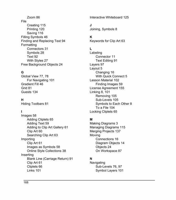
Zoom 86File
Creating 115Printing 120Saving 116
Filling Symbols 46Finding and Replacing Text 94Formatting
Connectors 31Symbols 28Text 92With Styles 27
Free Background Objects 24
GGlobal View 77, 78
For Navigating 101Gradient Fill 46Grid 81Guests 134
HHiding Toolbars 81
IImages 58
Adding Cliplets 65Adding Text 59Adding to Clip Art Gallery 61Clip Art 60Searching Clip Art 63
ImportingClip Art 61Images as Symbols 58Online Style Collections 38
InsertingBlank Line (Carriage Return) 91Clip Art 61Cliplets 66Links 101
Interactive Whiteboard 125
JJoining, Symbols 8
KKeywords for Clip Art 63
LLabeling
Connector 11Text Editing 91
Layers 97Layout 5
Changing 16With Quick Connect 5
Lesson Material 102Finding Images 59
License Agreement 155Linking 8, 101
Removing 105Sub-Levels 105Symbols to Each Other 8To a File 104
Locking Cliplets 65
MMaking Diagrams 3Managing Diagrams 115Merging Projects 137Moving
Connections 16Diagram Objects 14Objects 24On Workspace 87
NNavigating
Sub-Levels 76, 97Symbol Layers 101
168
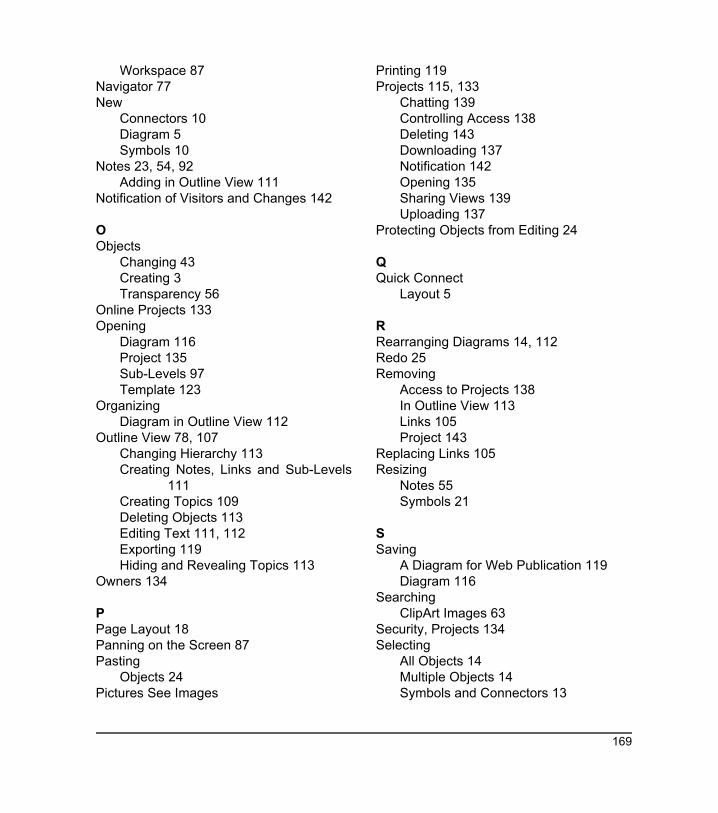
Workspace 87Navigator 77New
Connectors 10Diagram 5Symbols 10
Notes 23, 54, 92Adding in Outline View 111
Notification of Visitors and Changes 142
OObjects
Changing 43Creating 3Transparency 56
Online Projects 133Opening
Diagram 116Project 135Sub-Levels 97Template 123
OrganizingDiagram in Outline View 112
Outline View 78, 107Changing Hierarchy 113Creating Notes, Links and Sub-Levels
111Creating Topics 109Deleting Objects 113Editing Text 111, 112Exporting 119Hiding and Revealing Topics 113
Owners 134
PPage Layout 18Panning on the Screen 87Pasting
Objects 24Pictures See Images
Printing 119Projects 115, 133
Chatting 139Controlling Access 138Deleting 143Downloading 137Notification 142Opening 135Sharing Views 139Uploading 137
Protecting Objects from Editing 24
QQuick Connect
Layout 5
RRearranging Diagrams 14, 112Redo 25Removing
Access to Projects 138In Outline View 113Links 105Project 143
Replacing Links 105Resizing
Notes 55Symbols 21
SSaving
A Diagram for Web Publication 119Diagram 116
SearchingClipArt Images 63
Security, Projects 134Selecting
All Objects 14Multiple Objects 14Symbols and Connectors 13
169
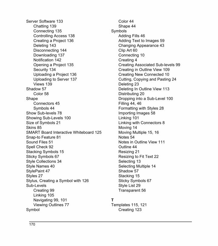
Server Software 133Chatting 139Connecting 135Controlling Access 138Creating a Project 136Deleting 143Disconnecting 144Downloading 137Notification 142Opening a Project 135Security 134Uploading a Project 136Uploading to Server 137Views 139
Shadow 57Color 58
ShapeConnectors 45Symbols 44
Show Sub-levels 78Showing Sub-Levels 100Size of Symbols 21Skins 85SMART Board Interactive Whiteboard 125Snap-to Feature 81Sound Files 51Spell Check 92Stacking Symbols 15Sticky Symbols 67Style Collections 34Style Names 40StylePaint 47Styles 27Stylus, Creating a Symbol with 126Sub-Levels
Creating 99Linking 105Navigating 99, 101Viewing Outlines 77
Symbol
Color 44Shape 44
SymbolsAdding Fills 46Adding Text to Images 59Changing Appearance 43Clip Art 60Connecting 10Creating 4Creating Associated Sub-levels 99Creating in Outline View 109Creating New Connected 10Cutting, Copying and Pasting 24Deleting 23Deleting In Outline View 113Distributing 20Dropping into a Sub-Level 100Filling 44, 46Formatting with Styles 28Importing Images 58Linking 101Linking with Connectors 8Moving 14Moving Multiple 15, 16Notes 54Notes in Outline View 111Outline 44Resizing 21Resizing to Fit Text 22Selecting 13Selecting Multiple 14Shadow 57Stacking 15Sticky Symbols 67Style List 29Transparent 56
TTemplates 115, 121
Creating 123
170
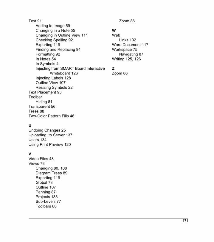
Text 91Adding to Image 59Changing in a Note 55Changing in Outline View 111Checking Spelling 92Exporting 119Finding and Replacing 94Formatting 92In Notes 54In Symbols 4Injecting from SMART Board Interactive
Whiteboard 126Injecting Labels 128Outline View 107Resizing Symbols 22
Text Placement 95Toolbar
Hiding 81Transparent 56Trees 88Two-Color Pattern Fills 46
UUndoing Changes 25Uploading, to Server 137Users 134Using Print Preview 120
VVideo Files 48Views 78
Changing 80, 108Diagram Trees 89Exporting 119Global 78Outline 107Panning 87Projects 133Sub-Levels 77Toolbars 80
Zoom 86
WWeb
Links 102Word Document 117Workspace 75
Navigating 87Writing 125, 126
ZZoom 86
171

172