concept of operations for - minnesota …€¦ · 1.1 basic traffic signal (bts) ... this document...
TRANSCRIPT

SYSTEMS ENGINEERING
CONCEPT OF OPERATIONS (ConOps)
for:
STANDARD TRAFFIC SIGNAL
MINNESOTA DEPARTMENT OF TRANSPORTATION
Contract Number: Approval Date: Prepared by: Document Control Number: Revision Version & Date:
V1 1/26/10

Table of Contents
1.0 .........................................................1 Purpose and Scope of Application Package
1.1 ..........................................................................2 Basic Traffic Signal (BTS)1.2 ....................................................................4 Flashing Yellow Arrow (FYA)1.3 .............................................................4 Advanced Warning Flasher (AWF)1.4
.......................................................................................................4 Railroad Preemption (RRP) of Traffic Signal at Railroad-Highway Grade Crossing
1.5 .......................................................7 Emergency Vehicle Preemption (EVP)1.6 .......................................................................9 Transit Signal Priority (TSP)1.7 .........................................................................11 Enforcement Lights (EnL)1.8 ............................................................11 Traffic Signal Coordination (TSC)1.9 ..........................................................................................................12 Other
2.0 ..........................................................................................13 Reference Documents3.0 ......................................................................13 Background and System Concept
3.1 ........................................................................13 Basic Traffic Signal (BTS)3.2 ..................................................................14 Flashing Yellow Arrow (FYA)3.3 ...........................................................14 Advanced Warning Flasher (AWF)3.4 .......................................................................14 Railroad Preemption (RRP)3.5 .....................................................14 Emergency Vehicle Preemption (EVP)3.6 .....................................................................14 Transit Signal Priority (TSP)3.7 .........................................................................14 Enforcement Lights (EnL)3.8 ............................................................15 Traffic Signal Coordination (TSC)3.9 ..........................................................................................................15 Other
4.0 ......................................................................................15 Operational Description4.1 ........................................................................15 Basic Traffic Signal (BTS)4.2 ..................................................................15 Flashing Yellow Arrow (FYA)4.3 ...........................................................15 Advanced Warning Flasher (AWF)4.4 .......................................................................15 Railroad Preemption (RRP)4.5 .....................................................16 Emergency Vehicle Preemption (EVP)4.6 .....................................................................16 Transit Signal Priority (TSP)4.7 .........................................................................16 Enforcement Lights (EnL)4.8 ............................................................16 Traffic Signal Coordination (TSC)4.9 ..........................................................................................................16 Other
5.0 ................................................................................................17 Operational Needs6.0 ....................................................................21 Operational Support Environment7.0 ............................................................................................23 Summary of ImpactsAppendix A. ITS Development Objectives ....................................................................26
ConOps i January 26, 2010 Standard Traffic Signal

ConOps ii January 26, 2010 Standard Traffic Signal
List of Tables Table 1 Standard Traffic Signal Needs & Functions by Stakeholder ............................... 17 Table 2 Traffic Signal Needs/Services and ITS Development Objectives ....................... 19
List of Figures Figure 1 Countdown Pedestrian Signal Display ................................................................. 3 Figure 2 Illustration of Use of Flashing Yellow Arrow in 2009 National MUTCD – Section 4 D Figures 4D-12 and 4D-14 ............................................................................... 5 Figure 3 Minnesota AWF per 2005 MN MUTCD, Section 4M ......................................... 6 Figure 4 Grade Crossing with Traffic Signal Preemption .................................................. 6 Figure 5 Traffic Signal Sequencing for Railroad Preemption ............................................ 8 Figure 6 Emergency Vehicle Preemption Concept ............................................................. 9 Figure 7 Transit Signal Priority Concept - with Optical Emitter ...................................... 10 Figure 8 Enforcement Lights on Back Side of Traffic Signal Face .................................. 12

1.0 PURPOSE AND SCOPE OF APPLICATION PACKAGE
This document provides a Concept of Operations (ConOps) for a standard traffic signal along with optional features that may apply to a particular project. Please see the corresponding Minnesota Statewide Regional ITS Architecture and Systems Engineering Checklist (Checklist) for the project to identify which specific features apply. Regardless of the selected options, all traffic signals include the operational concepts for the Basic Traffic Signal (item .1). Following are the name and numbering identifiers for the various features that may apply:
.1 – Basic Traffic Signal (BTS; common to all) .2 – Flashing Yellow Arrow (FYA) .3 – Advance Warning Flasher (AWF) .4 – Railroad Preemption (RRP) .5 – Emergency Vehicle Preemption (EVP) .6– Transit Signal Priority (TSP) .7 – Enforcement Lights (EnL) .8 – Traffic Signal Coordination (TSC) .9 – Other
For each section of this document where information is distinguished by optional feature, the section follows the numbering scheme per the above list. For example, Section 1.4 covers the purpose and scope for Railroad Preemption as applies to the traffic signal. A separate document addresses Traffic Signal Preemption ConOps from the railroad system perspective. The stakeholders, as per the Minnesota Statewide Regional ITS Architecture (March 2009); Statewide Architecture for short) for the traffic signal(s) will be all or nearly all of the following, depending on the specific feature:
Travelers: private vehicle drivers and passengers, transit operators and passengers, commercial operators, school bus operators and passengers, pedestrians (including those with disabilities), and bicyclists
Minnesota Department of Transportation (Mn/DOT) and associated entities: o District Offices o RTMC (Regional Transportation Management Center), plus
Transportation Operation and Communication Centers (TOCCs), o Office of Traffic, Safety, and Technology (OTST; formerly OTSO) o Office of Maintenance o Office of Transportation Data and Analysis (TDA)
Minnesota Department of Public Safety (DPS), plus Division of Driver and Vehicle Services (DVS)
Local Agencies: counties, cities, towns, villages, and townships Local Traffic Management Centers Local Maintenance and Construction Management (MCM) Agencies Local Transit Providers such as Metro Transit and others Railroad Companies
ConOps 1/29 January 26, 2010 Standard Traffic Signal

Minnesota State Patrol (MSP) and local law enforcement. Local Emergency Response and Incident Management Agencies: police, fire, and
ambulance Federal Highway Administration (FHWA) Federal Transit Administration (FTA) Federal Railroad Administration (FRA)
Notes to Stakeholder list:
Only Travelers is listed in the Statewide Architecture, but has been expanded above to explicitly list the various types of Travelers.
The list of Local Agencies has been similarly expanded from the Statewide Architecture.
Local law enforcement has been added in the MSP group. 1.1 Basic Traffic Signal (BTS) A traffic signal provides standard red-yellow-green operation to assign movement right-of-way, and will have actuated or fixed time operation plus the following:
Wiring for Emergency Vehicle Preemption (EVP). Design that follows the latest version of Americans with Disability Act
Accessibility Guidelines for Buildings and Facilities (ADAAG), as cited in the 2005 MN MUTCD.
Countdown Pedestrian Signal (CPS) faces that indicate time left in the pedestrian change interval (the flashing “don’t walk”).
Accessible Pedestrian Signals that provide both audio and vibrating surface information in a non-visual format, except in certain circumstances.
EVP wiring is included to allow for easy future addition of hardware and control software to facilitate safe and expeditious emergency vehicle movement on one or more approaches of the intersection (police, fire, ambulance). Following the ADAAG requires appropriate design with respect to signal pole, cabinet, and pedestrian detector placement. Reference guidance is provided in Sections 4D and 4E of the Minnesota MUTCD (the current version is 2005 MN MUTCD, expected to be updated in 2010). Mn/DOT as of early 2010 also is in the process of adopting the latest version of the Public Rights-of-Way Accessibility Guidelines (PROWAG) for general use with regards to pedestrian treatments at traffic signals. CPS faces provide second-by-second visual display of the number of seconds remaining in the pedestrian change interval, adjacent to the associated upraised hand (“Don’t Walk”; see Figure 1). The display counts down only during display of the adjacent flashing upraised hand, displays zero when the upraised hand changes to steady display, then blanks out. Section 4E.7 of the 2005 MN MUTCD spells out further details. The 2009 national MUTCD requires that CPS faces be provided on all new signals installed after December 22, 2013. Mn/DOT is including this feature on all new signal installations with pedestrian displays, and likely will retrofit existing pedestrian signal faces as they reach the end of their service life.
ConOps 2/29 January 26, 2010 Standard Traffic Signal

Figure 1 Countdown Pedestrian Signal Display (Source: Countdown Pedestrian Signals: A Comparison of Alternative Pedestrian
Change Interval Displays, by Westat for FHWA, March 2005)
Accessible Pedestrian Signals (APSs) provide information in non-visual format using both audible messages and vibrating surfaces, plus associated pedestrian signal timing. APS detection may also be needed, which may be active or passive. If it is active, a pushbutton locator tone is provided. Specific requirements and guidance are spelled out in Sections 4E.6 and .9 of the 2005 MN MUTCD. Of note, the pedestrian change interval timing may not be altered or omitted as part of a transition into a preemption sequence. Thus APS inclusion at railroad grade crossings must be carefully weighed against absolute preemption requirements of a specific crossing. The PROWAG discussed above could possibly mandate APS at all new or renovated pedestrian signal locations in the country. Once the U.S. Department of Justice adopts any future Access Board public right of way guidelines as a standard, the FHWA plans to reconsider the matter for future revisions of the national MUTCD (see Federal Register /Vol. 74, No. 240 /Wednesday, December 16, 2009 /Rules and Regulations, p66825, Item 408). Regardless of national developments, Minnesota intends to use APSs except in circumstances where other safety requirements take precedence. Placement of APS devices is particularly important so that persons making use of them can readily recognize where they are, to what crossing they apply, and can easily activate associated detection when part of the design. Appropriate spoken messages are defined in the 2005 MN MUTCD. Automatic volume adjustment is provided within specified limits. Vibrotactile devices communicate information about pedestrian timing through a vibrating surface by touch and indicate that the walk interval is in effect. They also indicate to which direction they apply through a vibrating directional arrow or some other means. A BTS may also include detection, and may be either isolated or part of a closed loop, interconnected system, as shown on project plans. If part of a system, supervisory operational aspects are not covered under this ConOps, instead only related site aspects are included.
ConOps 3/29 January 26, 2010 Standard Traffic Signal

1.2 Flashing Yellow Arrow (FYA) The FYA is a new optional feature in the 2009 national MUTCD (primarily Sections 4D.17-.30) that is expected to be adopted in Minnesota. It is used to delineate permissive left or right turn movement, as opposed to protected left or right turn movement, see Figure 2. It may be selectively included on approaches on which there is a permissive left- or right- turn phase, due to conflicting movement with either opposing vehicular traffic, or pedestrian movement across a conflicting cross walk. Mast arm length may need to be adjusted to accommodate an FYA signal face. 1.3 Advanced Warning Flasher (AWF) An AWF installation is the addition of a sign with flashing yellow sections to alert drivers approaching a high speed signalized intersection that the light is about to turn from the green phase to red phase. The purpose of a combination highway traffic signal and Advance Warning Flasher system is to: 1) inform the driver in advance of a required drive decision (prepare to stop), and 2) minimize the number of drivers that will be required to make that decision in the dilemma zone. Application details are given in Section 4M of the 2005 MN MUTCD. AWF operation is implemented by use of a sign with yellow flashers, as illustrated on Figure 3. The yellow flashers are activated any time an approaching vehicle is likely to arrive at the signal during a red signal phase. The exact timing of when to flash is a detailed design aspect on an individual site basis, discussed in 2005 MN MUTCD Section 4M. The overall goal is to alert drivers sufficiently in advance for maximum safety. 1.4 Railroad Preemption (RRP) of Traffic Signal at Railroad-Highway
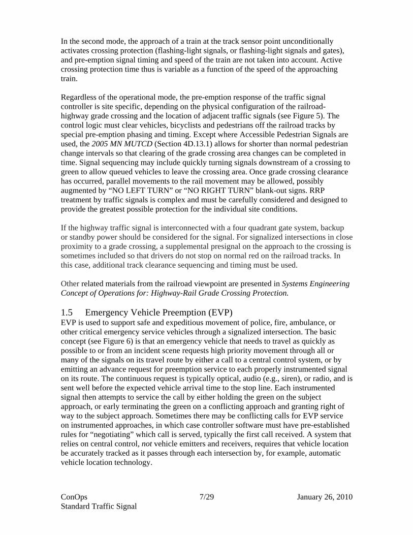
Grade Crossing RRP of a traffic signal is used to clear a railroad-highway grade crossing and maintain the clearance while the train passes to avoid a collision between the train(s) and vehicles or travelers including bicyclists and pedestrians (see Figure 4). The scope of RRP is heavy rail, i.e., operations in which the train cannot be expected to stop in time to avoid a collision with an object on the grade crossing. Light rail transit is considered a non-standard application that must be treated on a case-by-case basis. The approach of a train with RRP always preempts normal signal operation to clear the crossing and avoid a collision. Two basic operational modes are used that affect traffic signal clearance timing. In the first mode, activation of crossing protection (flashing-light signals, or flashing-light signals and gates) is programmed to occur a fixed time before the arrival of the railroad vehicle at the crossing. Typical minimum activation time before the train arrives is 20 seconds or more per the 2005 MN MUTCD, but is set at a nearly uniform value of constant warning time. To accomplish this, track sensors must be able to accurately measure the speed of the approaching train and estimate the arrival time to the crossing. Traffic signal clearance timing must then be related to the constant warning time for activating crossing protection.
ConOps 4/29 January 26, 2010 Standard Traffic Signal

Figure 2 Illustration of Use of Flashing Yellow Arrow in 2009 National MUTCD – Section 4 D Figures 4D-12 and 4D-14
ConOps 5/29 January 26, 2010 Standard Traffic Signal
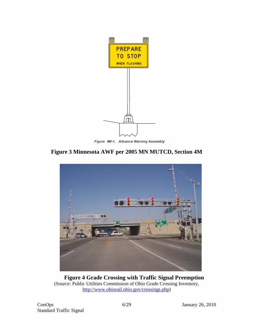
Figure 3 Minnesota AWF per 2005 MN MUTCD, Section 4M
Figure 4 Grade Crossing with Traffic Signal Preemption (Source: Public Utilities Commission of Ohio Grade Crossing Inventory,
http://www.ohiorail.ohio.gov/crossings.php)
ConOps 6/29 January 26, 2010 Standard Traffic Signal
In the second mode, the approach of a train at the track sensor point unconditionally activates crossing protection (flashing-light signals, or flashing-light signals and gates), and pre-emption signal timing and speed of the train are not taken into account. Active crossing protection time thus is variable as a function of the speed of the approaching train. Regardless of the operational mode, the pre-emption response of the traffic signal controller is site specific, depending on the physical configuration of the railroad-highway grade crossing and the location of adjacent traffic signals (see Figure 5). The control logic must clear vehicles, bicyclists and pedestrians off the railroad tracks by special pre-emption phasing and timing. Except where Accessible Pedestrian Signals are used, the 2005 MN MUTCD (Section 4D.13.1) allows for shorter than normal pedestrian change intervals so that clearing of the grade crossing area changes can be completed in time. Signal sequencing may include quickly turning signals downstream of a crossing to green to allow queued vehicles to leave the crossing area. Once grade crossing clearance has occurred, parallel movements to the rail movement may be allowed, possibly augmented by “NO LEFT TURN” or “NO RIGHT TURN” blank-out signs. RRP treatment by traffic signals is complex and must be carefully considered and designed to provide the greatest possible protection for the individual site conditions. If the highway traffic signal is interconnected with a four quadrant gate system, backup or standby power should be considered for the signal. For signalized intersections in close proximity to a grade crossing, a supplemental presignal on the approach to the crossing is sometimes included so that drivers do not stop on normal red on the railroad tracks. In this case, additional track clearance sequencing and timing must be used. Other related materials from the railroad viewpoint are presented in Systems Engineering Concept of Operations for: Highway-Rail Grade Crossing Protection. 1.5 Emergency Vehicle Preemption (EVP) EVP is used to support safe and expeditious movement of police, fire, ambulance, or other critical emergency service vehicles through a signalized intersection. The basic concept (see Figure 6) is that an emergency vehicle that needs to travel as quickly as possible to or from an incident scene requests high priority movement through all or many of the signals on its travel route by either a call to a central control system, or by emitting an advance request for preemption service to each properly instrumented signal on its route. The continuous request is typically optical, audio (e.g., siren), or radio, and is sent well before the expected vehicle arrival time to the stop line. Each instrumented signal then attempts to service the call by either holding the green on the subject approach, or early terminating the green on a conflicting approach and granting right of way to the subject approach. Sometimes there may be conflicting calls for EVP service on instrumented approaches, in which case controller software must have pre-established rules for “negotiating” which call is served, typically the first call received. A system that relies on central control, not vehicle emitters and receivers, requires that vehicle location be accurately tracked as it passes through each intersection by, for example, automatic vehicle location technology.
ConOps 7/29 January 26, 2010 Standard Traffic Signal

Figure 5 Traffic Signal Sequencing for Railroad Preemption (Source: Traffic Signal Operations Near Highway-Rail Grade Crossings,
NCHRP Synthesis 271)
ConOps 8/29 January 26, 2010 Standard Traffic Signal

Figure 6 Emergency Vehicle Preemption Concept
Approaching emergency vehicle typically sends optical, audio, or radio signal requesting signal preemption. Unlike RRP, EVP is not usually absolute.
(Source: http://solutions.3M.com , Opticom ™ product graphic, now owned/distributed by Global Traffic Technologies, www.gtt.com/Traffic-Management )
Unlike RRP, EVP is not absolute in the sense that preemption is not necessarily granted in all cases, for example, when EVP has already been granted for an emergency vehicle on a conflicting approach. Confirmatory white/clear indicator lights are required per the 2005 MN MUTCD (Section 4D.13.1) to indicate to emergency vehicle drivers whether or not they have been granted preemption. The 2005 MN MUTCD (Section 4D.13.1) allows for shorter than normal pedestrian change intervals so that the required clearing of the grade crossing area changes can be completed in time. The passage of the emergency vehicle through the intersection typically means that the call for service is no longer received by the signal controller, and it returns the signal to normal operational mode. 1.6 Transit Signal Priority (TSP) TSP is similar to EVP but with a lower priority to force a green extension or early truncation of red (see Figure 7). Typical implementations are based on active tracking of bus passage times relative to scheduled passage times at route checkpoints. If a bus is running ahead of schedule, TSP activation is inappropriate because it may then put the bus further ahead of schedule. Usually a bus needs to be a few minutes or more behind schedule to justify putting in a call for priority service. Another consideration is that in more urbanized areas, requests for priority may occur on conflicting approaches of a given signalized intersection, so there must be a rule such as “first calling, first served.”
ConOps 9/29 January 26, 2010 Standard Traffic Signal

More sophisticated systems could theoretically keep track of number of passengers on board, and in the case of approximately same time requests on conflicting approaches, grant priority to the bus with significantly higher passenger count. Most US transit bus systems today, however, do not track number of passengers on board in real time.
Figure 7 Transit Signal Priority Concept - with Optical Emitter
Approaching bus typically sends optical, audio, or radio signal requesting priority at signal if it is behind schedule a certain amount. This involves local intelligence to determine bus schedule performance. TSP operates at lower priority than both RRP and EVP.
(Source: “Bus Priority in Portland - Lessons Learned”, by B. Kloos, http://www.docstoc.com/docs/DownloadDoc.aspx?doc_id=19006315)
The scope of TSP addressed here is operation in which all vehicle tracking and priority decisions are made locally, that is, a transit system control center is not involved in monitoring bus position and schedule adherence to decide on whether or how to grant transit priority. The level of priority to grant must be determined on an individual route or site basis. The location of bus stop affects the determination of this, with near side stops having the additional complication that bus dwell time for boarding and alighting passengers is variable such that the true desired “green” time for the bus is not known very long in advance. Far side stop placement simplifies the control algorithm because a bus requesting priority is always requesting to make it through the signal at its expected arrival time to the stop line. As with EVP, calls for priority can be accomplished by a number of methods including optical, audio, or radio emitters/receivers. In general, it is desirable that TSP along, or crossing, a progressively timed arterial be fit into the overall timing plan, not disrupting coordinated operations. In this way, servicing of the call should have the least adverse impact on normal signal operation, and in some cases may improve flow along the major traffic route. Although bus TSP operation is shown in Figure 7, TSP also can support light rail transit operations where grade crossings with highways typically occur frequently. In this case,
ConOps 10/29 January 26, 2010 Standard Traffic Signal

TSP may be combined with special traffic signal preemption depending on the needs of the site. 1.7 Enforcement Lights (EnL) EnL are special displays placed on the back or the side of signal heads for the benefit of an enforcement officer to see when the red is displayed, as shown on Figure 8. This allows the enforcement officer to see whether or not a driver has illegally entered the intersection approach on red and should have a violation cited. Minnesota State Law requires that the enforcement officer observe and issue tickets for red light running, i.e., automated red light running cameras are not allowed. Design of EnL is on a site basis, taking into account where a police officer can safely park to observe the light and then enter traffic to catch up to the offending vehicle. The need for EnL should be established based on crash records or observed patterns of red light running that tend to support the installation. 1.8 Traffic Signal Coordination (TSC) TSC is the establishment of timed traffic flow between traffic signals on a progressively timed arterial or in a grid to minimize delays and stops. The Mn/DOT Traffic Signal Timing and Coordination Manual discusses signal timing and coordination, all of which is dependent on setting up coordination plans by time of day and day of week, or on use of traffic responsive/adaptive signal timing. The signals may be interconnected via wireline or wireless communications, or progressive timing may be established using time-based coordination in which very accurate internal clocks are used to maintain timing schedules. If signal interconnection is used, timing plan settings and parameters can be controlled remotely and the signals can be monitored to confirm signal operations in a closed loop configuration. With interconnection, the remote location may be a traffic management center, an agency desktop computer, or possibly a technician’s laptop computer via a secure connection over the internet. An on-street master may be part of the system supervising a defined arterial or small network, or the signals may connect directly to a central control location. The central control location may contact the on-street masters to provide oversight and direction. Intersection controllers may collect volume, occupancy, and occasionally speed data locally for performance monitoring and timing plan development. This information may be immediately conveyed to the central control location or locally stored for later retrieval. System supervision and oversight may be by standard closed loop signal packages from established suppliers or may use custom software. Project design documents must clearly lay out the operational needs and constraints, and then define the supervisory and oversight software. Similarly, project design must define the technology and performance requirements of the communications subsystem that connects the signals. The TSC scope here is standard signal systems and not “smart” or “enhanced” corridors that in addition may have closed circuit TV (CCTV) cameras, dynamic message signs (DMS), and other equipment.
ConOps 11/29 January 26, 2010 Standard Traffic Signal

Figure 8 Enforcement Lights on Back Side of Traffic Signal Face
(Source: Mn/DOT photo files) 1.9 Other [Reserved for new features and their characteristics. Please consult with appropriate Mn/DOT, FHWA, or local staff to develop needed scope description.] Additional detail on needs and functions served for the traffic signal features is presented in Section 4.0 Operational Needs, below. ConOps 12/29 January 26, 2010 Standard Traffic Signal
2.0 REFERENCE DOCUMENTS Reference sources, including traffic signal design and operation documents, follow. The latest adopted version of each document should apply.
“Intelligent Transportation System Architecture and Standards,” (CFR 940), Federal Highway Administration (FHWA) Final Rule, 23 CFR Parts 655 and 940
Minnesota Statewide Regional ITS Architecture, March 2009 Mn/DOT Intelligent Transportation System (ITS) Design Manual, Fall 2009 Minnesota Traffic Engineering Manual Various traffic signal planning, design, and operations references cited at
http://www.dot.state.mn.us/trafficeng/designtools/index.html Minnesota Manual on Uniform Traffic Control Devices (2005 MN MUTCD ,
available at http://www.dot.state.mn.us/trafficeng/otepubl/mutcd/) Mn/DOT Traffic Signal Timing and Coordination Manual, March 2009 MN/DOT DOC ON HWY-RL GATE DOWN LOGIC-PLEASE PROVIDE
CITATION NEMA Standards Publication TS-1 or TS-2 Local agency traffic signal specifications and design guidelines, as applicable National Electric Code Mn/DOT Standard Specifications for Construction, latest edition The Americans with Disabilities Act Accessibility Guidelines for Buildings and
Facilities (ADAAG) Public Rights-of-Way Accessibility Guidelines (PROWAG) as adopted by
Mn/DOT Guidelines for Accessible Pedestrian Signals and Accessible Pedestrian Signals:
A Guide to Best Practices, both completed as part of National Cooperative Highway Research Program (NCHRP) Project 3-62, available at http://www.accessforblind.org/aps_resources.html .
3.0 BACKGROUND AND SYSTEM CONCEPT 3.1 Basic Traffic Signal (BTS) Traffic signal installation and operation is justified based on an Intersection Control Evaluation (ICE). An important part of an ICE is consideration of traffic signal warrants in Chapter 4C of the 2005 MN MUTCD. The warrants by name are:
Warrant 1, Eight-Hour Vehicular Volume. Warrant 2, Four-Hour Vehicular Volume. Warrant 3, Peak Hour. Warrant 4, Pedestrian Volume. Warrant 5, School Crossing. Warrant 6, Coordinated Signal System. Warrant 7, Crash Experience. Warrant 8, Roadway Network.
ConOps 13/29 January 26, 2010 Standard Traffic Signal

Traffic signals serve to provide safe and efficient movement of conflicting traffic flows by enforcing control discipline that balances demands for green time among the conflicting approaches. Traffic signals are more efficient than stop signs once traffic volumes reach a certain level because they remove the uncertainty regarding which approach has the assigned right of way (green time) at any moment. Properly designed and timed, they also tend to result in safer operations than stop signs at heavy traveled intersections for the same reason. At signalized locations with pedestrian indications and potentially push buttons, signals afford safe movement of pedestrians across the busy intersection approaches and roadways. 3.2 Flashing Yellow Arrow (FYA) FYA has been developed with support from research in the National Cooperative Highway Research Program (see http://www.trb.org/Main/Public/Blurbs/159759.aspx). The overall intent is to improve operational efficiency while maintaining safe permissive left- and right-turn movements. The 2009 national MUTCD provides this as an option based on engineering judgment. Minnesota is expected to include the option with other updates to the MN MUTCD based on the new national MUTCD. Appropriate documentation needs to be on file and maintained by the implementing agency. 3.3 Advanced Warning Flasher (AWF) The approaches selected for AWF installation are to have been identified based on field studies, plan review, or the fundamental nature of the site(s). Appropriate documentation needs to be on file and maintained by the implementing agency. 3.4 Railroad Preemption (RRP) RRP, EVP, and TSP are all versions of signal preemption and priority, in decreasing order of application based on the relative order of importance or difficulty in stopping the type or class of vehicle. In all cases, traffic signal planning, design, and operation must be carefully executed to maximize safety and efficiency. The most complex situations are those in which all three types are present at the same signalized intersection. Appropriate documentation needs to be on file and maintained by the implementing agency in all cases. 3.5 Emergency Vehicle Preemption (EVP) See RRP. 3.6 Transit Signal Priority (TSP) See RRP. 3.7 Enforcement Lights (EnL) EnL will be in use in Minnesota at least until such time that the State passes legislation allowing the use of automated red light running cameras. Appropriate documentation needs to be on file and maintained by the implementing agency.
ConOps 14/29 January 26, 2010 Standard Traffic Signal

3.8 Traffic Signal Coordination (TSC) For ConOps and functional requirements for more sophisticated levels of traffic control than basic on-street master, closed loop control, additional documentation should be prepared on a site-specific basis. Even in the case of basic closed loop control, planning, design, and operational documentation may be substantial. 3.9 Other Other features generally can be expected to require substantial documentation to justify and explain new technologies and applications. 4.0 OPERATIONAL DESCRIPTION The major operational aspects of signals are covered under 4.1 Basic Traffic Signal and apply to all signal features (4.2 through .11). A few additional aspects for some of the features are also identified. 4.1 Basic Traffic Signal (BTS) Operations, management, and maintenance of the traffic signal(s) will be the responsibility of the owning or assigned operational agency. The primary actions will be to:
Establish traffic signal timing based on site volumes, geometrics, signal phasing and controller capabilities,
Periodically check and conduct routine maintenance on the traffic signal approaches,
Promptly respond to trouble calls to maintain satisfactory operation in case of performance failure or knock-down
Review crash data periodically to assure that the signalized intersection is operating as safely as can be expected, and
Review performance data periodically (e.g., stops, delays, queue lengths) to assure satisfactory levels are achieved, potentially resulting in signal timing adjustments and possible recommendations for geometric improvements.
4.2 Flashing Yellow Arrow (FYA)
No additional actions. 4.3 Advanced Warning Flasher (AWF)
Establish AWF timing (initiation and termination times of flashing) based on signal phasing and controller capabilities.
4.4 Railroad Preemption (RRP)
Establish RRP preemption sequencing, phasing, and timing based on site physical and control features, emphasizing “fail safe” operation.
ConOps 15/29 January 26, 2010 Standard Traffic Signal

4.5 Emergency Vehicle Preemption (EVP) Establish EVP preemption sequencing, phasing, and timing based on site physical
and control features, and how competing requests for preemption on conflicting approaches will be resolved.
4.6 Transit Signal Priority (TSP)
Establish TSP priority timing based on site physical and control features, including rules for servicing requests on conflicting approaches and limits on the frequency of priority grants allowed.
4.7 Enforcement Lights (EnL)
No additional actions. 4.8 Traffic Signal Coordination (TSC)
Establish initial traffic signal timing plans based on system volumes and geometrics, potentially running traffic signal timing software. If traffic responsive signal operation included, establish plan selection parameters.
4.9 Other
[Reserved for new features and their operational actions].
ConOps 16/29 January 26, 2010 Standard Traffic Signal

5.0 OPERATIONAL NEEDS The needs and functions of the signal for each of the stakeholders are presented in Table 1.
Table 1 Standard Traffic Signal Needs & Functions by Stakeholder STAKEHOLDER TRAFFIC SIGNAL NEEDS & FUNCTIONS
Travelers: private vehicle drivers and passengers, transit operators and passengers, commercial operators, school bus operators and passengers, and bicyclists
BTS-1 Safe and efficient assignment of vehicle right-of-way, with reliable and predictable service. BTS-2 Clear, unambiguous display of red-yellow-green signal indications. BTS-3 Minimum delay and stops, to the extent possible. Additional Needs and Functions by traffic signal feature: AWF-1 Adequate warning of signalized approach ahead, preparing drivers to stop RRP-1 Fail-safe operation that minimizes the possibility of vehicles, objects or persons occupying grade crossing area when a train passes EVP-1 Safe and expeditious movement of emergency vehicles through traffic signals TSP-1 For Transit Operators and Passengers, better service by extension of green time or early truncation of red thus reducing delay, improving schedule reliability, and reducing run time. TSC-1 Traffic Signal Coordination - Coordinated signal operation with adjacent signals. Other – [Please consult with appropriate Mn/DOT, FHWA, or local staff to develop needed Needs and Functions]
Pedestrians (including disabled)
PED-1 Provide safe pedestrian crossings of signalized approaches in marked crosswalks. PED-2 Clear and unambiguous pedestrian signal section displays. PED-3 Pedestrian detection by push button when warranted. PED-4 Adherence to ADAAG in design and construction. PED-5 Adequate “start-up” WALK time, followed by sufficient clearance FLASHING DON’T WALK time. PED-6 Pedestrian timing based on walking speed of 3.5 feet per second or less due to, for example, disabled or elderly population. PED-7 For impaired or disabled populations, easy to find detection/push buttons and explicit communication of “WALK/DON”T WALK” message.
ConOps 17/29 January 26, 2010 Standard Traffic Signal

ConOps 18/29 January 26, 2010 Standard Traffic Signal
Table 1 (continued) STAKEHOLDER TRAFFIC SIGNAL NEEDS & FUNCTIONS
All Stakeholders share in above to varying degree. Further specific Needs and Functions follow: Mn/DOT, Mn/DOT District Offices, Mn/DOT Office of Maintenance, RTMC, OTST, and TDA; Local Agencies, MCM units, and Traffic Management Centers; FHWA
BTS-4 Well-designed traffic signal that meet agency performance standards or guidelines for effective operations and safety. BTS-5 Easily maintained and operated signal per agency standards using interoperable and easily replaced equipment and parts. BTS-6 Data archiving of vehicle detection data and signal operations for use in planning and performance monitoring wherever and whenever possible.
Railroad Companies, FRA
RRP-2 Reliable and easily maintained link between track circuit and nearby traffic signal(s) to provide and safe and effective actuation of active grade crossing protection with flashing-light signals, or flashing-light signals and gates.
TOCCs, Local Emergency Response and Incident Management Agencies: police, fire and ambulance
EVP-2 Signal preemption on selected approaches, including verification via visual display.
Local Transit Providers, FTA
TSP-2 More effective use of resources (buses and labor) by extension of green time or early truncation of red thus reducing run time.
Minnesota DPS, DVS, MSP, and local law enforcement
EnL-1 Monitoring of red light running with an effective tool that facilitates enforcement and issuance of citations for driver violations.
The Needs and Services plus associated ITS Development Objectives, per the Statewide Architecture, are presented in Table 2. For reference, the complete list of ITS Development Objectives is presented in Appendix A. It should be noted that some of the standard application groups meet an ITS Development Objective without an identified Need or Service in the Statewide Architecture. The Needs and Services are mapped to identified functional requirements in the companion Functional Requirements for Standard Traffic Signal.

Table 2 Traffic Signal Needs/Services and ITS Development Objectives by Standard Traffic Signal Feature
ID Feature
TS-BTS Basic Traffic Signal TM01 Provide efficient signal timing
TM03 Use archived data for traffic management strategy development and long range planning.
TM14 Monitor operation and performance of traffic signalsTM37 Provide safe signal phase transition
--
TS-BTS: Pedestrian Aspects --
PEDTS-BTS: Detection Aspects TM01 Provide efficient signal timing
DET TM33 Provide intersection collision avoidance systemsTM37 Provide safe signal phase transition
TS-BTS: Monitoring Aspects TM14Monitor operation and performance of traffic signals
MON --
TS-BTS: Interface Aspects TM01 Provide efficient signal timing
IFCTS-FYA Flashing Yellow Arrow TM01 Provide efficient signal timing
TM37 Provide safe signal phase transition--
TS-AWF Advanced Warning Flasher TM33 Provide intersection collision avoidance systems
TM37 Provide safe signal phase transition--
O-24, O-26
O-12
O-8, O-9
O-5, O-10, O-14
O-24, O-26
Needs/Services
O-2, O-12, O-13, O-43
O-8, O-9
O-24, O-26
O-5, O-10, O-14
ITS Development Objectives
O-24, O-26
O-41, O-42
O-5, O-10, O-14
O-5, O-10, O-14
O-12
O-13
O-24, O-26
O-24, O-26
O-36, O-41, O-42
ConOps 19/29 January 26, 2010 Standard Traffic Signal
ConOps 20/29 January 26, 2010 Standard Traffic Signal
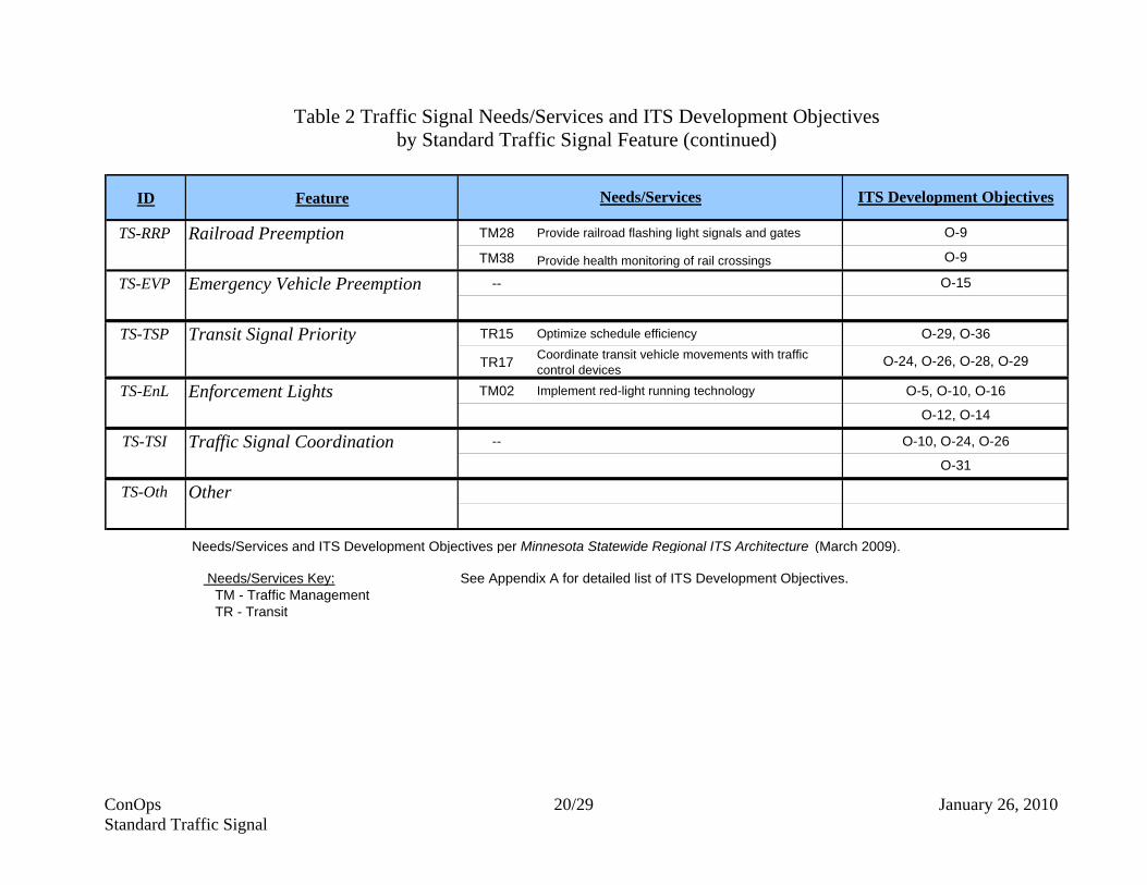
Table 2 Traffic Signal Needs/Services and ITS Development Objectives by Standard Traffic Signal Feature (continued)
ID Feature
TS-RRP Railroad Preemption TM28 Provide railroad flashing light signals and gates
TM38 Provide health monitoring of rail crossings
TS-EVP Emergency Vehicle Preemption --
TS-TSP Transit Signal Priority TR15 Optimize schedule efficiency
TR17 Coordinate transit vehicle movements with traffic control devices
TS-EnL Enforcement Lights TM02 Implement red-light running technology
TS-TSI Traffic Signal Coordination --
TS-Oth Other
Needs/Services and ITS Development Objectives per Minnesota Statewide Regional ITS Architecture (March 2009).
Needs/Services Key: See Appendix A for detailed list of ITS Development Objectives. TM - Traffic Management TR - Transit
O-15
O-9
O-29, O-36
O-24, O-26, O-28, O-29
Needs/Services ITS Development Objectives
O-5, O-10, O-16
O-12, O-14
O-10, O-24, O-26
O-31
O-9

6.0 OPERATIONAL SUPPORT ENVIRONMENT 6.1 Basic Traffic Signal (BTS) The operational support environment will use standard traffic signal timing and maintenance techniques that are well developed within Mn/DOT, or Local Agencies. Technicians will operate and maintain the traffic signal(s) using agency operational guidelines along with routine and emergency maintenance procedures that are well established. Signal operation is to be in conformance with the 2005 MN MUTCD. With respect to operational scenarios, the most important maintenance aspect once signal timing has been prepared and implemented is defined procedures for trouble calls. Trouble calls will typically originate from various sources: the general public, police, and Mn/DOT or Local Agency personnel who drive through the subject approach[es] either as a part of assigned work, or as a private citizen, e.g., while commuting to and from work. Mn/DOT or Local Agency policy and contract requirements typically define required response times on weekdays, weekends, holidays, and overnight. Response time (time interval from initial fault notification until an on-site maintenance vehicle arrives or diagnosing from a remote location begins) varies by type and severity of fault, as well as intersection priority. Periodic operational and safety reviews need to be conducted particularly with respect to APS user volumes, potentially leading to adjustment in APS operations and timing. Preventive maintenance on the intersection(s) will be scheduled to occur periodically as a part of routine traffic signal maintenance. Signal timing reviews can be expected to occur on a periodic schedule of at least every three years, based on performance data from each site, or based on operational observations and citizen complaints. Review of site performance from a crash history viewpoint may be completed periodically by Mn/DOT or Local Agency personnel. 6.2 Flashing Yellow Arrow (FYA) As presented in section 1.2, the FYA operating scenario is the display of a flashing yellow arrow when permissive vehicle movement is allowed, that is, the controlled left- or right-turn traffic must yield to opposing conflicting traffic or conflicting pedestrians. Also, FYA operations typically are localized to each site with no communication of occurrences to a central location. As a result, FYA operations do not generate additional system architecture needs. Specialized maintenance may be required depending on how FYA operation is implemented. 6.3 Advanced Warning Flasher (AWF) The AWF operation scenario is relatively straightforward, as described in Section 1.3 above, in which the yellow flasher is activated to warn approaching drivers that the signal has turned, or is about to turn, to red. Each site is essentially an isolated operation that does not depend on information from other locations, nor does it typically communicate AWF operations to a central location. As a result, there are no additional system architecture needs. If central monitoring is included, a wireline or wireless connection between the site and the central location must be established. The system architecture to handle the required data flows must be included in detailed site design.
ConOps 21/29 January 26, 2010 Standard Traffic Signal

AWF operation is a special extension of standard traffic signal procedures. The critical aspect is determination of when to initiate and terminate flasher operation within the framework of normal signal phasing and timing, per 2005 MN MUTCD Section 4M. A minimum amount of training in this aspect may be required. Periodic operational reviews need to be conducted, potentially leading to adjustment in AWF activation and termination timing to maximize the safety benefit. 6.4 Railroad Preemption (RRP) Section 1.4 describes the operational scenarios. The interface between the track circuit and the traffic signal and the associated signal preemption timing are critical aspects that must be carefully developed and, if necessary, fine tuned. RRP also requires regular routine maintenance and quick response in case of performance failure or trouble call within a few hours at most. Although the operations of each site is standalone, remote monitoring of the preemption circuitry that sends alarm messages to both the railroad and the highway authority in the case of a malfunction is desirable. The system architecture and associated communications for this are dependent on characteristics of both the rail system and the traffic signal operation. Specialized training is required to handle operations and maintenance. Periodic operational and safety reviews need to be conducted, potentially leading to adjustment in RRP activation timing. 6.5 Emergency Vehicle Preemption (EVP) Section 1.5 describes the operational scenarios. Appropriate rules for negotiating competing calls for EVP must be established, along with treatment of pedestrian phase timing that may be operational when a call is received. Initial set up and operation can be expected to require adjustment of sensitivity and range parameters that vary by the technology used. Most sites operate standalone, with no communications to a central oversight point. The exception is an EVP system that tracks emergency vehicles using automatic vehicle location technology and issues commands on the route to hold greens or truncate reds. In this case, the system architecture and associated communications are dependent on characteristics of the traffic signal system. Specialized training is required to handle operations and maintenance. Periodic operational and safety reviews need to be conducted, potentially leading to adjustment in EVP timing. 6.6 Transit Signal Priority (TSP) Section 1.6 describes the operational scenarios. Appropriate rules for negotiating competing calls for TSP must be established, along with limits on frequency of priority grants. Per the 2005 MN MUTCD, shortening of pedestrian interval timing is generally not allowed for TSP. Most sites operate standalone, with no communications to a central oversight point. The exception is a TSP system that tracks transit vehicles using automatic vehicle location technology and issues requests along the route to hold greens or truncate reds if the transit vehicle is significantly behind schedule. In this case, the system architecture and associated communications are dependent on characteristics of the transit management and traffic signal systems. Specialized training is required to handle operations and maintenance. Periodic operational and safety reviews need to be conducted, potentially leading to adjustment in TSP operations and timing.
ConOps 22/29 January 26, 2010 Standard Traffic Signal

6.7 Enforcement Lights (EnL) Section 1.9 describes the operational scenario. Sites operate standalone so there are no system architecture aspects. Maintenance is essentially the same as for standard signal sections, so no special training is required. 6.8 Traffic Signal Coordination (TSC) Sections 1.10 and 4.10 discuss operational scenarios, focusing on development of coordinated signal timing settings and parameters for interconnected traffic signals. Sites are by definition interconnected so that system architecture and communications configuration need to be developed based on physical characteristics and communications medium. Some specialized training in communications technology is generally required. Periodic operational reviews need to be conducted, potentially leading to adjustment in signal system timing. 6.9 Other
[Reserved for new features and their scenarios]. 7.0 SUMMARY OF IMPACTS 7.1 Basic Traffic Signal (BTS) Depending on site conditions, traffic signals should achieve less vehicle delay, fewer stops, less fuel consumption and emissions, and safer operation than alternate methods of traffic control such as stop signs, roundabouts, or manual police control. The impacts will vary across stakeholders, since stakeholder interests and objectives almost always need to be balanced against one another. For example, providing adequate pedestrian crossing time of a major arterial at a signal will often result in increased stops and delay to major arterial traffic. Thus it is important that the competing objectives be identified at the outset of signal concept and detailed design, and that periodic performance evaluation be conducted to assure that the objectives are reasonably achieved. Overall agency goals and objectives may be reconsidered and redirected from time to time as well, and such redirection may affect periodic performance evaluation. APS operation focuses on providing the same information to disabled persons as to others to help them make the correct crossing decision. One potential metric is safety performance, along with the degree to which drivers properly observe the rights of pedestrians in cross walks. This may require special studies of “challenged” crossings in which pedestrians are threatened by vehicles. A second potential metric is the comprehensibility of the APS to the target population, that is, the effectiveness and clarity in conveying the “WALK/DON’T WALK” message. The two metrics should be related to one another. CPS installations should improve pedestrian safety by removing uncertainty about remaining crossing clearance time. Quantifying the benefit, however, may be difficult because of the many factors that affect pedestrian safety at intersections. It is likely that pedestrian involvement in crashes will need to be aggregated over several crossings and fairly long time periods to demonstrate benefits.
ConOps 23/29 January 26, 2010 Standard Traffic Signal

7.2 Flashing Yellow Arrow (FYA) The primary benefit of FYA installation is flexibility in signal operation that should yield more efficient vehicle movement with reduced delay. Ideally, time-and-delay studies are conducted to verify the results while accident occurrence is also reviewed to confirm that safe turn operations are maintained. Based on these assessments, site modifications may be appropriate, such as relocation of signal heads or conversion to protected only turn operation. 7.3 Advanced Warning Flasher (AWF) The primary impact associated with AWF installation is reduction or prevention of adverse crash occurrence. The key metric will be annual crash data in terms of absolute number, severity, and rate, relative to similar signalized approaches that do not have AWF. Based on this assessment, alternate timing parameters may be implemented, or the location of the AWF may be modified to be more prominent or to provide additional stopping time for approaching drivers.
7.4 Railroad Preemption (RRP) RRP is focused on safe operation of this critical interface between rail and highway systems, given the likely severity of any crashes that occur. Accident records need to be reviewed on a regular basis. Every grade crossing crash should be evaluated to see if further design or operational treatments might be employed to reduce the potential for future incidents. 7.5 Emergency Vehicle Preemption (EVP) EVP aims to provide the fastest possible incident response time. The implementing agency should track response times and attempt to provide reasonable metrics for evaluating EVP performance. The difficulty in this is the variability in emergency conditions, in terms of route, time of day, traffic, and weather conditions. EVP also needs to be safe, that is, not result in increase in, and ideally reduce, collisions between emergency vehicles and other traffic. Presumably the “base case” will involve few such accidents, but emergency agencies should track safety trends. 7.6 Transit Signal Priority (TSP) TSP has two primary benefits: reduced travel time/increased schedule reliability for passengers, and more efficient use of equipment by transit operating agencies. The transit operator should conduct before and after studies to determine the degree to which these benefits are achieved. Improved passenger service may attract additional ridership, so this aspect should be considered as well. 7.7 Enforcement Lights (EnL) The primary goal of ENL is reduction in red light running occurrence and associated crashes. The lights also provide a safer environment for enforcement officers who no longer have to follow an offending vehicle through a red light. Crash data should thus be carefully tracked to see if in fact a safety benefit is realized. A secondary benefit may be a reduction in red light running at all signalized intersections, based on the positive benefits of active enforcement. Thus evaluation should consider both specific installation site and general area performance with respect to those crashes that may be affected by reduction in red light running.
ConOps 24/29 January 26, 2010 Standard Traffic Signal

7.8 Traffic Signal Coordination (TSC) TSC should result in reduced stops and delay on the road system by improved synchronization of signals. This may be measured through before and after time-and-delay studies of travel time that quantify effects of improved coordination. Stop and delay reductions can be translated into fuel and emissions savings. Interconnected signals may also provide quicker notification of malfunctioning than might otherwise occur. 7.9 Other [Reserved for new feature impacts.]
ConOps 25/29 January 26, 2010 Standard Traffic Signal

APPENDIX A. ITS DEVELOPMENT OBJECTIVES Source: Minnesota Statewide Regional ITS Architecture (March 2009)
General Purpose: Create a system that enhances transportation through the safe and efficient movement of people, goods, and information, with greater mobility and fuel efficiency, less pollution, and increased operating efficiency in Minnesota. A. Improve the Safety of the State’s Transportation System
A-1. Reduce crash frequency (ATMS, ATIS, APTS, CVO, EM, MCM & AVSS) O-1 Reduce crashes due to road weather conditions O-2 Reduce crashes due to unexpected congestion O-3 Reduce secondary crashes O-4 Reduce incident clearance time O-5 Reduce crashes due to red-light running O-6 Reduce crashes due to unsafe drivers, vehicles and cargo on the
transportation system O-7 Reduce lane departure crashes O-8 Reduce crashes due to roadway/geometric restrictions O-9 Reduce crashes at railroad crossings O-10 Reduce crashes at intersections O-11 Reduce speed differential O-12 Reduce crashes due to driver errors and limitations O-13 Reduce crashes involving pedestrians or non-motorized vehicles O-14 Reduce violation of traffic laws
A-2. Reduce fatalities and life changing injuries (ATMS, ATIS, CVO, EM, MCM & AVSS) O-5 Reduce crashes due to red-light running O-9 Reduce crashes at railroad crossings O-10 Reduce crashes at intersections O-11 Reduce speed differential O-15 Reduce emergency/incident response time O-16 Enhance emergency/incident response effectiveness O-17 Safeguard public safety personnel while they are at roadway incidents and
emergencies O-18 Reduce speed violations
A-3. Safeguard the motoring public from homeland security and/or Hazmat incidents (ALL) O-15 Reduce emergency/incident response time O-19 Reduce security risks to transit passengers and transit vehicle operators O-20 Reduce security risks to motorists and travelers O-21 Reduce security risks to transportation infrastructure O-22 Reduce exposure due to Hazmat & homeland security incidents O-23 Enhance tracking and monitoring of sensitive Hazmat shipments
A-4. Reduce crashes in work zones (ATMS, ATIS, EM & MCM) O-4 Reduce incident clearance time O-11 Reduce speed differential O-24 Reduce congestion and delay O-25 Enhance safety of workers
ConOps 26/29 January 26, 2010 Standard Traffic Signal

B. Increase Operational Efficiency and Capacity of the Transportation System B-1. Reduce overall delay associated with congestion (ATMS, ATIS & MCM)
O-4 Reduce incident clearance time O-15 Reduce emergency/incident response time O-16 Enhance emergency/incident response effectiveness O-24 Reduce congestion and delay O-26 Maintain smooth traffic flow O-27 Reduce incident detection and verification time
B-2. Increase average vehicle occupancy and facility throughput (ATMS & APTS) O-28 Increase transit ridership O-29 Enhance transit operations efficiency O-30 Increase carpoolers O-31 Increase throughput of roadways
B-3. Reduce delays due to work zones (ATMS, ATIS, EM & MCM) O-4 Reduce incident clearance time O-24 Reduce congestion and delay O-26 Maintain smooth traffic flow
B-4. Reduce traffic delays during evacuation from homeland security and Hazmat incidents (ALL) O-24 Reduce congestion and delay
B-5. Enhance efficiency at borders (ATMS, CVO, EM & AVSS) O-32 Reduce delays at border crossings O-33 Keep travelers informed of travel conditions
C. Enhance Mobility, Security, Convenience, and Comfort for the Transportation
System User C-1. Reduce congestion and incident-related delay for travelers (ATMS, ATIS & APTS)
O-4 Reduce incident clearance time O-15 Reduce emergency/incident response time O-16 Enhance emergency/incident response effectiveness O-24 Reduce congestion and delay O-26 Maintain smooth traffic flow O-27 Reduce incident detection and verification time O-34 Enhance parking facility services and management
C-2. Improve travel time reliability (ATMS) O-24 Reduce congestion and delay O-26 Maintain smooth traffic flow
C-3. Increase choice of travel modes (APTS & ATMS) O-33 Keep travelers informed of travel conditions O-35 Inform travelers of travel mode options
C-4. Enhance traveler security (APTS & EM) O-19 Reduce security risks to transit passengers and transit vehicle operators O-20 Reduce security risks to motorists and travelers O-21 Reduce security risks to transportation infrastructure
C-5. Reduce stress caused by transportation (ATMS, ATIS, APTS, EM & MCM) O-3 Reduce secondary crashes O-11 Reduce speed differential O-14 Reduce violation of traffic laws O-18 Reduce speed violations O-24 Reduce congestion and delay O-29 Enhance transit operations efficiency
ConOps 27/29 January 26, 2010 Standard Traffic Signal

O-33 Keep travelers informed of travel conditions O-34 Enhance parking facility services and management O-35 Inform traveler of travel mode options
D. Enhance the Present and Future Economic Productivity of Individuals, Organizations and the Economy as a Whole D-1. Reduce travel time for freight, transit and businesses (ATMS, ATIS, APTS & CVO)
O-24 Reduce congestion and delay O-26 Maintain smooth traffic flow O-29 Enhance transit operations efficiency O-33 Keep travelers informed of travel conditions
D-2. Improve the efficiency of freight movement, permitting and credentials process (ATIS & CVO) O-33 Keep travelers informed of travel conditions O-36 Enhance asset and resource management O-37 Enhance credential process automation O-38 Reduce freight movement delays due to inspection
D-3. Improve travel time reliability for freight, transit and businesses (ATMS, APTS & CVO) O-26 Maintain smooth traffic flow O-29 Enhance transit operations efficiency O-33 Keep travelers informed of travel conditions O-38 Reduce freight movement delays due to inspection
D-4. Increase agency efficiency (ATMS, APTS, AD, CVO, EM & MCM) O-29 Enhance transit operations efficiency O-36 Enhance asset and resource management O-39 Enhance garage operations efficiency
D-5. Safeguard existing infrastructure (CVO, EM & MCM) O-21 Reduce security risks to transportation infrastructure O-36 Enhance asset and resource management O-40 Reduce commercial vehicle size and weight violations
D-6. Aid in transportation infrastructure and operations planning (ALL) O-36 Enhance asset and resource management O-41 Enhance planning with better data O-42 Enhance investment decision making
D-7. Reduce vehicle operating costs (ATMS, APTS, CVO & AVSS) O-24 Reduce congestion and delay O-26 Maintain smooth traffic flow
E. Reduce Energy Consumption, Environmental Impacts and Costs of Transportation
E-1. Reduce emissions/energy impacts and use associated with congestion (ATMS, ATIS & CVO) O-24 Reduce congestion and delay O-33 Keep travelers informed of travel conditions O-43 Enhance compliance of air quality standards
E-2. Reduce need for new facilities (ATMS,CVO & MCM) O-31 Increase throughput of roadways O-36 Enhance asset and resource management O-37 Enhance credential process automation
ConOps 28/29 January 26, 2010 Standard Traffic Signal

ConOps 29/29 January 26, 2010 Standard Traffic Signal
E-3. Reduce negative impacts of the transportation system on communities (APTS,
ATMS, EM & MCM) O-14 Reduce violation of traffic laws O-28 Increase transit ridership O-30 Increase carpoolers O-44 Reduce environmental impacts of de-icing material use
AD: Archived Data Management AVSS: Advanced Vehicle Safety Systems APTS: Advanced Public Transportation Systems CVO: Commercial Vehicle Operations ATIS: Advanced Traveler Information Systems EM: Emergency Management ATMS: Advanced Traffic Management Systems MCM: Maintenance and Construction Management