concord - twothirds · pdf fileeocr say goodbye to motor ... entire range of electronic motor...
TRANSCRIPT
CONCORD
http://www.cacindia.net
ISO 9001 : 2008
NABCBQ M 0 3 0
U®
Electronic Overload Relays...Electronic Overload Relays...
EOCR
SAY GOODBYE TO MOTOR FAILURES

CONCORD
CONCORD has been the pioneer of the Electronic Motor Protection technology in the Indian market with innovative and useful products for
the Industry since 1997. We design build and supply a vast array of Electronic Protection Relays and our vision is to become the best supplier
for Motor protection and Motor management for its customers nationwide.
We will continue to offer the best technology at most competetive prices to our users to help them stay abreast with the most demanding and
competetive enviornments globally. We will also strive to attain service and distribution levels for our Protection Relays that will set a new
benchmark for the customers satisfaction.
As always our focus will be to assist our customers in acheiving their goals of safely securing the finite natural resources before it’s too late
and help save on precious natural reserves and expensive down times in their respective industries thereby reducing our carbon footprints for
our next generations.
Our products always have and will be designed to last very long and continuously work to protect your energy, materials & manpower costs.
Keeping in mind our local working conditions at various locations across the country the products we will supply to our customers will be
world class.
In our efforts, we hope to serve our customers to their exacting requirements and with our Quality Management systems based on ISO 9001
2008 we gaurantee the highest quality products and services. Manufactured under stringent Quality procedures all our products conform to
latest relevant international standards.
OVERVIEW
The 3 Phase Electric Motor, is the workhorse of every industry and failure to notice unwarranted conditions can lead to disastrous results. The
entire range of Electronic Motor Protection Relays offered by CONCORD are chosen carefully based on our experience and understanding of
the needs of different users. All models offered by us are unique and different from each other in terms of Protections offered and principle of
operation so that the user has the unique advantage of choosing the right product for their applications.
By choosing the right protection device, users can ensure longer life from their motors and avoid untimely failures resulting in loss of
manpower, materials and natural resources like copper for rewinding procedures. Despite having conventional electro mechanical products
for motor protection, it is a known fact that notor failures are quite common and lead to execcesive costs, downtime and loss of materials in
process. which are far greater than the cost of the motor and allied protection equipment.
In the kind of conditions that prevail in our industry, it is not uncommon to have Over or Under Voltage, Loss of one Phase, Change of Phase
Sequence, Bearing failures due to high levels of dust and pollution, Over heating, Jamming or stalling of rotors, Very frequent start stop
operation of motors, Initial High Torque requirements etc All of these conditions lead to premature motor failures and fault diagnosis is
seemingly not possible after the motor has failed, because most of the times the failed part is a result of another unattended problem which
was not addressed on time.
As there is not much data to confirm exact cause of Motor failures, it makes it even more imperative to move from Reactive and Preventive
maintenence to Diagnostic and Predictive maintenence to save on valuable resources and time. Here is why Electronic Motor Protection
Relays are more useful to the industry hereby saving precious resources, time and money.

Electronic Overload Relays...Electronic Overload Relays...
SALIENT FEATURES
�����
Compact Design
2/3 Integral Current Transformers
Multiple Protection Features
Wide Current Ajustment Range
Solid State / MCU based Circuits
�����
Ammeter Function
Trip Indication/ Fault Diagnosis
Highly Accurate
Looping Options
Manual/ Electrical Remote Reset
����
Test Function
Suitable for use with External CT’s upto 600A
Ambient Insensitive
Low Energy Consumption
D-TIME (Starting Delay Time)
O-TIME ( Operating Time on Overload)
TEST FUNCTION
Looping Option
The D-Time is the time taken by the motor before it reaches it’s
normal running current. During start the motor draws much higher
levels of current and the D-Time setting is to ensure that the EOCR
does not cause any nuiscance trippings before this set time has
elapsed. After the D-Time setting is over the relay monitors the
normal running currents.
O-Time is the operating time in the event of overload. When motor
current exceeds the desired set current value, the EOCR detects
the increase and trips the motor within the set O-Time preventing
excess heating and long periods of overload.
The TEST function facility on the front face of the relay is provided
to check the health status of the relay without electrically
energizing the relay. On pressing the TEST button the internal relay
will trip after the D-Time + O-Time settings have elapsed. After
using this test facility, the RESET button has to be pressed to
operate the relay
Looping option is required in case the amount of current
measurement is desired to be more accurate and precise. The wire
from the main line when passing through the Internal EOCR CT is
looped one or more times depending upon the current range of the
relay to suit the application.
RESET FUNCTION
EXTERNAL CT OPTION
By pressing the RESET button or disconnecting the electrical
supply will trip the relay immediately. Once the relay has tripped
due to any Over Load or any other fault, the relay has to be reset to
start the motor again.
By usinf External CT’s with secondary rating of 5A the EOCR can be
ised to monitor and protect motors with
normal running currents of upto 600A.
This is used with an 05 Type relay with
current setting range of 0.5 - 6A. In
Digital models the display current
values are selectable as desired.
CAUSES OF MOTOR FAILURE IN INDUSTRY - GENERAL
Shaft Coupling
Unknown
External
Stator Winding
Loss of Phase
Bearing
Motor Failure Data
[A] 1x 3x2x 4x 5x-05
-30
-60
0,5-6
2,5-30
5-60
0,25-3
1,25-15
5-60
0,17-2
0, 83-10
1,7-20
0,13-1,5
0,83-7,5
1,25-15
0,1-1,2
0,5-6
1-12
Setting Ranges
Full Load Current
Set Current
TR
IP
D-Time
Normal Load
O-Time
CURRENT
TIM
E

EOCR SS - SOLID STATE PROTECTION RELAY
CONCORD
�
�
�
�
2 Integral Current Transformer’s
Electronic Shear Pin Function
Independently Adjustable D-Time and O-Time
Independent Mounting
SPECIFICATIONS
Current Setting Type Range
05 0.5-6A
30 3-30A
60 5-60A
100A and above With External CT
Time Setting Start(D-Time) 0.2-30sec
Trip (O-Time) 0.2-10sec
Control Voltage 220 90-260VAC
440 320-480VAC
Contact Rating Mode 1SPDT(1C)
Rating 3A 250VAC
Status Normally
Energized
Time Current
Characteristic Definite
Operating
(Trip Indication) 2 LED
Mounting 35mm DIN Rail/Base
TRIPPING CHARACTERISTIC - DEFINITEAPPLICATIONS
PROTECTION FUNCTIONS
Overcurrent O-Time
Phase Loss O-Time
Locked Rotor O-Time + D-Time
WIRING DIAGRAM
Tr.
L1
L2
95
96
98
EO
CR
SS
M
MC
MC ON
OFF/RESET
L1 L2 L3
OVERALL DIMENSIONS
54
54
63
65
44
16
10
5 - M3.58.4DIN RAIL TYPE
5
BRACKET HOLE SIZE
FEATURES
TIME ( sec)
Adju
sta
ble
Current
0.21
0 1 2 3 4 5 6
30
TRIPPING CHARACTERISTIC - DEFINITE
Refer to Curve for EOCR SS on Right hand side Multiples of Current Setting
LT Motors, Pumps, Fans, Machine Tools, OEM's Panels etc.

Electronic Overload Relays...Electronic Overload Relays...
EOCR DS - MCU BASED PROTECTION RELAY
OVERALL DIMENSIONS
FEATURES
�
�
�
�
3 Integral Current Transformers
Independently adjustable D-Time and O-Time
Independent Mounting
Run Monitor and Fault Diagnosis with 2 LED’s
SPECIFICATIONS
Current Setting Type Range
05 0.5-6A
30 3-30A
60 5-60A
100A and above With External CT
Time Setting Start(D-Time) 1 - 50sec
Trip (O-Time) 0.2-10sec
Control Voltage 220 180-260VAC
Contact Rating Mode 1SPDT(1C)
Rating® 3A 250VAC
Status Normally
Energized
Time Current
Characteristic Definite
Operating
(Trip Indication) 2 LED with Fault Diagnosis
Mounting 35mm DIN Rail/Base
TRIPPING CHARACTERISTIC - DEFINITE
Refer to Curve for EOCR DS on previous on right hand side
PROTECTION FUNCTIONS
Overcurrent O-Time
Phase Loss Within 4 seconds
Locked Rotor Within D-Time
Phase Reverse 0.1sec
WIRING DIAGRAM
L1
L2
95
96
97
98
N
R
MC
MC
EOCR DS3
M
L1 L2 L3
Tr.
OFF/RESET
ON
58
46
12
10
76-M3.5
39
69
81
28
48
R 2.5 R 2.2
MOUNTING BRACKET
APPLICATIONSTRIPPING CHARACTERISTIC - DEFINITE
TIME ( sec)
Adju
stable
Current
0.21
0 1 2 3 4 5 6
30
Multiples of Current Setting
LT Motors, Pumps, Fans, Machine Tools, OEM's Panels etc.

CONCORDELECTRONIC PROTECTION RELAYS WITH DIGITAL DISPLAY AND FAULT DIAGNOSIS
INTRODUCTION
The complete range of Digital Motor Protection Relays from
CONCORD are designed for use with 3 Phase motors. The
inherent design features are built to make Motor protection far
easier and more accurate. The Digital Diplay works as an Ammeter
dsiplaying the actual motor current and also acts as Diagnostic
Display highlighting the various causes of motor tripping to assist
the user in trouble shooting and drastic reduction in downtime
whenever an Electrical fault occurs in the system.
These relays are built using a MCU - Microprocessor Control Unit
and are suitable for use for a very wide range of appli cations and
motor sizes. The Test function button enables the user to use the
same model for motor sizes ranging from 0.5A - 600A. There by
resulting in drastic reducion of inventories.
Insensitive to the Ambient temperatures and designed to suit local
conditions these Relays offer you Total Motor Protection and
gaurantee peace of mind.
UNDERSTANDING THE DISPLAY SYSTEM
Digital Display for
Fault Diagnosis and
Current Display
Under Normal
conditions the actual
motor current
in all 3 phases is
displayed
sequentially
Adjust Values
of Current and Time
during inital set up
before start
The LED signals the
value of the Display
items in Amperes
or seconds
Reset button to reset
the Relay in case of test
or actual Trip
Setting Adjustment
Button to set different
Values for
Current and Time

Electronic Overload Relays...Electronic Overload Relays...
TIME ( sec)
Adju
stable
CurrentMultiples of Current Setting
0.21
0 1 2 3 4 5 6
30
5 5
10 10
20 20
30 30
0.1
1
1 2 4 6 8 10
10
100
1000
10000TIME (sec)
CURRENTMultiples of Current Setting
HOT
COLD
UNDERSTANDING THE DISPLAY SYSTEM
3 Phase Motor Currents/ Leakage Current
in 3EZ model are displayed sequentially
on the LED Display as indicated below
EOCR 3DE model
EOCR 3EZ model
PROTECTION FUNCTIONS
L1L2L3
Amp
sec
L1L2L3
Amp
sec
L1L2L3
Amp
sec
L1L2L3
Amp
sec
L1L2L3
Amp
sec
L1L2L3
Amp
sec
L1L2L3
Amp
sec
L1L2L3
Amp
sec
Over Current Trip detected in L1 phase
Under Current Trip detected in L2 phase
Phase Loss Trip caused by L2 phase failure
Reverse Phase Trip caused by wrong phase sequence
Phase Unbalance Trip caused by phase unbalance in L1 phase
Ground Fault Trip caused by ground fault current only for EOCR 3EZ
Locked Rotor Trip caused by Locking/Jammimg of rotor during starting state
Locked Rotor Trip caused by Locking/Jammimg of rotor while motor is working
8 8 8 8L1L2L3
LED LED
Seven Segment Display(SSD)
65 70 75 80 85 90 95 100%
PhaseIndicationL1/L2/L3
Bar graph
Amp - amperex 10sec - second
Amp
x 10
sec
L1
L2
L3 3 90L1 Current Display
5 sec5 sec
Amp
x 10
sec
L1
L2
L3 3 90L3 Current Display
Amp
x 10
sec
L1
L2
L3 3 90L1 Current Display
Amp
x 10
sec
L1
L2
L3 3 90L1 Current Display
Amp
x 10
sec
L1
L2
L3 3 80L1 Current Display
Amp
x 10
sec
L1
L2
L3 3 90L3 Current Display
Amp
x 10
sec
L1
L2
L3 8 19Ground fault Current Display
5 sec
5 sec 5 sec
5 sec
5 sec
TIME Vs CURRENT CHARACTERISTIC CURVE - USER SELECTABLE
O-T Setting Curve IEC 947-4 Trip Class
1 - 5 10A 6 - 10 10A 11 - 20 20A 21 - 30 30A
INVERSE CURVE with SW3-INV/On Position DEFINITE CURVE with SW3-DEF/Off Position
PROTECTION FUNCTIONS
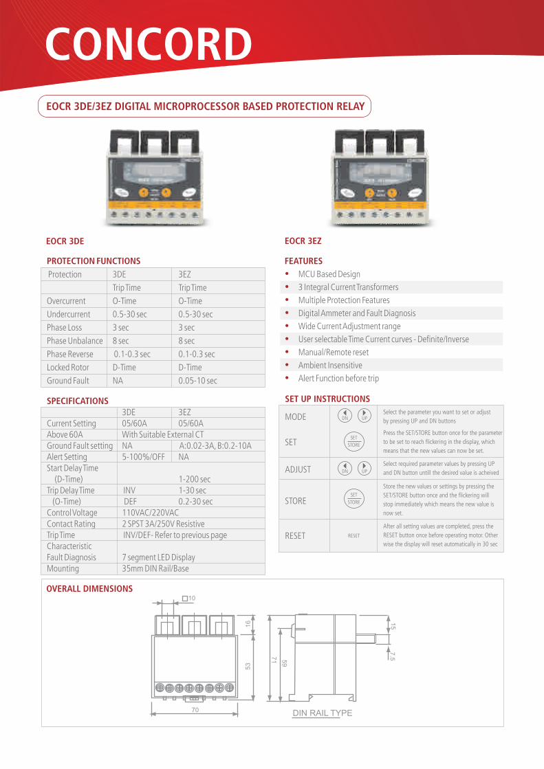
Protection 3DE 3EZ
Trip Time Trip Time
Overcurrent O-Time O-Time
Undercurrent 0.5-30 sec 0.5-30 sec
Phase Loss 3 sec 3 sec
Phase Unbalance 8 sec 8 sec
Phase Reverse 0.1-0.3 sec 0.1-0.3 sec
Locked Rotor D-Time D-Time
Ground Fault NA 0.05-10 sec
EOCR 3DE EOCR 3EZ
FEATURES
�
�
�
�
�
�
�
�
�
MCU Based Design
3 Integral Current Transformers
Multiple Protection Features
Digital Ammeter and Fault Diagnosis
Wide Current Adjustment range
User selectable Time Current curves - Definite/Inverse
Manual/Remote reset
Ambient Insensitive
Alert Function before trip
SPECIFICATIONS 3DE 3EZCurrent Setting 05/60A 05/60AAbove 60A With Suitable External CTGround Fault setting NA A:0.02-3A, B:0.2-10AAlert Setting 5-100%/OFF NAStart Delay Time (D-Time) 1-200 secTrip Delay Time INV 1-30 sec (O-Time) DEF 0.2-30 secControl Voltage 110VAC/220VACContact Rating 2 SPST 3A/250V ResistiveTrip Time INV/DEF- Refer to previous pageCharacteristicFault Diagnosis 7 segment LED DisplayMounting 35mm DIN Rail/Base
SET UP INSTRUCTIONS
DN UPSelect the parameter you want to set or adjust
by pressing UP and DN buttons
Press the SET/STORE button once for the parameter
to be set to reach flickering in the display, which
means that the new values can now be set.
Select required parameter values by pressing UP
and DN button untill the desired value is acheived
Store the new values or settings by pressing the
SET/STORE button once and the flickering will
stop immediately which means the new value is
now set.
DN UP
After all setting values are completed, press the
RESET button once before operating motor. Other
wise the display will reset automatically in 30 sec
SET
STORE
SET
STORE
RESET
MODE
SET
ADJUST
STORE
RESET
OVERALL DIMENSIONS
EOCR 3DE/3EZ DIGITAL MICROPROCESSOR BASED PROTECTION RELAY
DIN RAIL TYPE70
10
16
53
71 59
15
7.5
CONCORD
Electronic Overload Relays...Electronic Overload Relays...
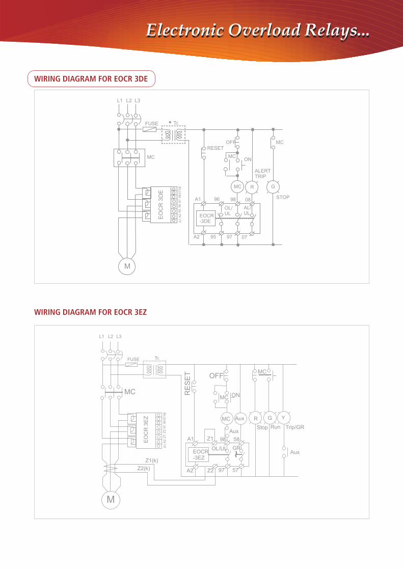
WIRING DIAGRAM FOR EOCR 3DE
WIRING DIAGRAM FOR EOCR 3EZ
L1 L2 L3
FUSE Tr.*
MCE
OC
R 3
DE
M
RESETOFF MC
MCON
ALERTTRIP
R GMC
STOP
EOCR-3DE
A1
A2
96 98
95 97 07
08
OL/UL
AL/UL
A1
A2
95
96
97
98
07
08
EO
CR
3E
Z
A1
A2
Z1
Z2
97
98
57
58
L1 L2 L3
FUSE Tr.
MC Aux
MC RE
SE
T OFFMC
MC ON
R G Y
Stop Run
Aux
AuxTrip/GR
GROL/ULEOCR-3EZ
A1
A2
Z1
Z2 97
98 58
57
M
Z2(k)
Z1(k)
~
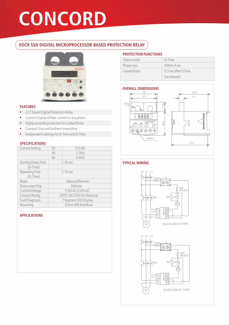
EOCR SSD DIGITAL MICROPROCESSOR BASED PROTECTION RELAY
FEATURES
�
�
�
�
�
2 CT based Digital Protection Relay
Current Display of Max. current in any phase
Highly accurate protection for Locked Rotor
Compact Size and Ambient Insensitive
Independent settings for D-Time and O-Time
PROTECTION FUNCTIONS
Overcurrent O-Time
Phase Loss Within 4 sec
Locked Rotor 0.5 sec after D Time
has elapsed
SPECIFICATIONSCurrent Setting 05 0.5-6A
30 3-30A60 5-60A
Starting Delay Time 1-30 sec (D-Time)Operating Time 1-10 sec (O-Time)Reset Manual/Remote Overcurrent Trip DefiniteControl Voltage 110V AC/220V ACContact Rating 2SPST 3A/250V AC ResistiveFault Diagnosis 7 Segment LED DisplayMounting 35mm DIN Rail/Base
APPLICATIONS
OVERALL DIMENSIONS
TYPICAL WIRING
8 8 8 8 CONCORD
12
6-M3.5
50
.81
9.5
58
51
62.2
10
77.2
L1 L2 L3
Fuse Tr.
MC MC
MC
ON
OFF(RESET)
A1A295969798
M EOCR SSD N TYPE
L1 L2 L3
Fuse Tr.
MC MC
MC
ON
OFF(RESET)
A1A295969798
M EOCR SSD R TYPE
CONCORD

Electronic Overload Relays...Electronic Overload Relays...
EUCR - SOLID STATE - ELECTRONIC UNDER CURRENT RELAY
FEATURES
�
�
�
�
�
2 Integral Current Transformer’s
Underload/ Dry Run Protection
Wide Current Adjustment Range
Definite Trip Time charcateristic
Manual/ Remote Reset
SPECIFICATIONSCurrent Setting Type Range
05 0.5-6A 30 3-30A 60 5-60A
100A and above With External CTTime Setting Trip Time 0.2 - 30 secControl Voltage 220 90-260VAC
440 320-480VACContact Rating Mode 1SPDT(1C)
Rating® 3A 250VAC Status Normally
EnergizedTime CurrentCharacteristic DefiniteOperating(Trip Indication) LEDMounting 35mm DIN Rail/Base
OVERALL DIMENSIONS
WIRING DIAGRAM
TRIPPING CHARACTERISTIC - DEFINITE
PROTECTION FUNCTIONS
Undercurrent U-Time
APPLICATIONS
54
54
63
65
44
16
10
5 - M3.58.4DIN RAIL TYPE
5
BRACKET HOLE SIZE
Tr.
L1
L2
95
96
98
EU
CR
SS
M
MC
MC ON
OFF/RESET
L1 L2 L3
TIME ( sec)
Adju
stable
CurrentMultiples of Current Setting
0.21
0 1 2 3 4 5 6
30
Belt Driven Systems, Pumps, Fans, Machine Tools, OEM's, Panels etc.

All Specifications, images and photos are proprietary and cannot be used without the owners permission. Specifications subject to change without any notice.
All Information given in this document is for reference purpose only and cannot be used against the company.
CONCORD AUTOMATION & CONTROLS
G 43, DLF Industrial Estate, 1 Faridabad
121003 Haryana (INDIA)
Phone : 0129 2278256, 2273860
Mobile : +91 9810659379
Fax : 0129 2273850
Email : [email protected]
Website : http://www.cacindia.net
Available in your area with: