concurrent cfd for catia v5 - flotrend.com.t · concurrent cfd for catia v5. ... most users report...
TRANSCRIPT
M e c h a n i c a l a n a l y s i s
w w w . m e n t o r . c o m
FloEFDTM
Concurrent CFD
for CATIA V5
w w w. m ento r.co m2
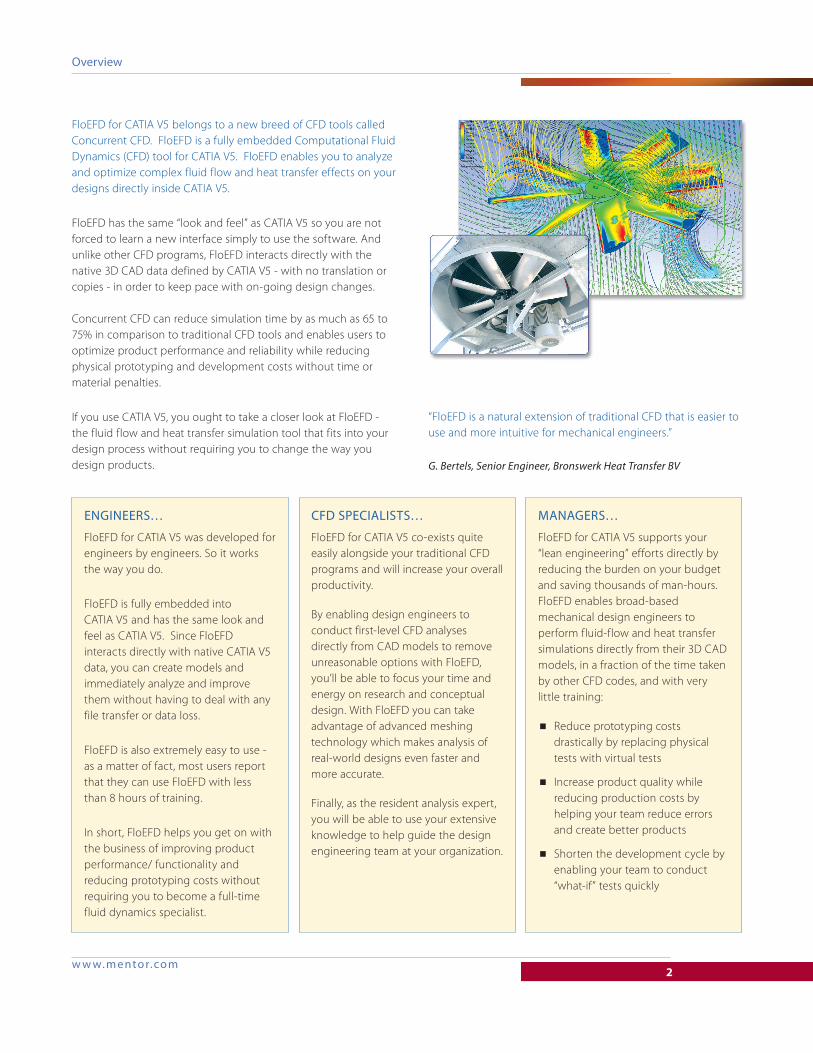
FloEFD for CATIA V5 belongs to a new breed of CFD tools called Concurrent CFD. FloEFD is a fully embedded Computational Fluid Dynamics (CFD) tool for CATIA V5. FloEFD enables you to analyze and optimize complex fluid flow and heat transfer effects on your designs directly inside CATIA V5.
FloEFD has the same “look and feel” as CATIA V5 so you are not forced to learn a new interface simply to use the software. And unlike other CFD programs, FloEFD interacts directly with the native 3D CAD data defined by CATIA V5 - with no translation or copies - in order to keep pace with on-going design changes.
Concurrent CFD can reduce simulation time by as much as 65 to 75% in comparison to traditional CFD tools and enables users to optimize product performance and reliability while reducing physical prototyping and development costs without time or material penalties.
If you use CATIA V5, you ought to take a closer look at FloEFD - the fluid flow and heat transfer simulation tool that fits into your design process without requiring you to change the way you design products.
engineers…
FloEFD for CATIA V5 was developed for engineers by engineers. So it works the way you do.
FloEFD is fully embedded into CATIA V5 and has the same look and feel as CATIA V5. Since FloEFD interacts directly with native CATIA V5 data, you can create models and immediately analyze and improve them without having to deal with any file transfer or data loss.
FloEFD is also extremely easy to use - as a matter of fact, most users report that they can use FloEFD with less than 8 hours of training.
In short, FloEFD helps you get on with the business of improving product performance/ functionality and reducing prototyping costs without requiring you to become a full-time fluid dynamics specialist.
cFD specialists…
FloEFD for CATIA V5 co-exists quite easily alongside your traditional CFD programs and will increase your overall productivity.
By enabling design engineers to conduct first-level CFD analyses directly from CAD models to remove unreasonable options with FloEFD, you’ll be able to focus your time and energy on research and conceptual design. With FloEFD you can take advantage of advanced meshing technology which makes analysis of real-world designs even faster and more accurate.
Finally, as the resident analysis expert, you will be able to use your extensive knowledge to help guide the design engineering team at your organization.
Managers…
FloEFD for CATIA V5 supports your “lean engineering” efforts directly by reducing the burden on your budget and saving thousands of man-hours. FloEFD enables broad-based mechanical design engineers to perform fluid-flow and heat transfer simulations directly from their 3D CAD models, in a fraction of the time taken by other CFD codes, and with very little training:
■ Reduce prototyping costs drastically by replacing physical tests with virtual tests
■ Increase product quality while reducing production costs by helping your team reduce errors and create better products
■ Shorten the development cycle by enabling your team to conduct “what-if” tests quickly
“FloEFD is a natural extension of traditional CFD that is easier to use and more intuitive for mechanical engineers.”
G. Bertels, Senior Engineer, Bronswerk Heat Transfer BV
Overview

w w w. m ento r.co m3
“FloEFD results are easy to understand and interpret by any engineer who is already familiar with the subject-matter being studied.”
A. Heijmans, Development Manager, Eclipse Combustion
FloEFD for CATIA V5 is a fully embedded CFD tool for CATIA V5 - effectively fluid flow and heat transfer analysis becomes an extension of CATIA V5 capabilities
We selected FloEFD for CATIA V5 because it simplifies the process of performing fluid flow analysis to the point where it can be accomplished by any engineer. By using CFD software that is integrated into our CAD software we could evaluate the performance of each new design iteration almost as fast as we could conceive it.”
D. Gaisbacher, Project Manager, Ventrex Automotive
w w w. m ento r.co m4
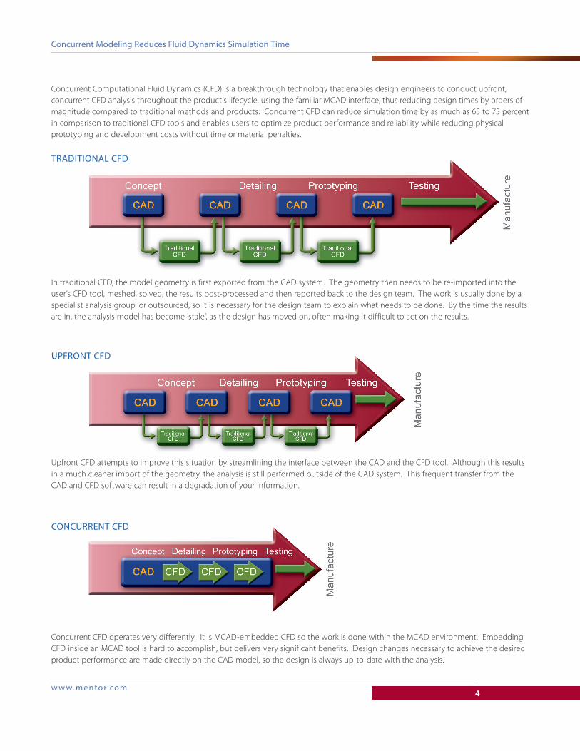
Concurrent Computational Fluid Dynamics (CFD) is a breakthrough technology that enables design engineers to conduct upfront, concurrent CFD analysis throughout the product’s lifecycle, using the familiar MCAD interface, thus reducing design times by orders of magnitude compared to traditional methods and products. Concurrent CFD can reduce simulation time by as much as 65 to 75 percent in comparison to traditional CFD tools and enables users to optimize product performance and reliability while reducing physical prototyping and development costs without time or material penalties.
traDitiOnal cFD
In traditional CFD, the model geometry is first exported from the CAD system. The geometry then needs to be re-imported into the user’s CFD tool, meshed, solved, the results post-processed and then reported back to the design team. The work is usually done by a specialist analysis group, or outsourced, so it is necessary for the design team to explain what needs to be done. By the time the results are in, the analysis model has become ‘stale’, as the design has moved on, often making it difficult to act on the results.
UpFrOnt cFD
Upfront CFD attempts to improve this situation by streamlining the interface between the CAD and the CFD tool. Although this results in a much cleaner import of the geometry, the analysis is still performed outside of the CAD system. This frequent transfer from the CAD and CFD software can result in a degradation of your information.
cOncUrrent cFD
Concurrent CFD operates very differently. It is MCAD-embedded CFD so the work is done within the MCAD environment. Embedding CFD inside an MCAD tool is hard to accomplish, but delivers very significant benefits. Design changes necessary to achieve the desired product performance are made directly on the CAD model, so the design is always up-to-date with the analysis.
concurrent Modeling reduces Fluid Dynamics simulation time
w w w. m ento r.co m5
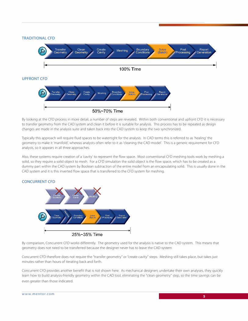
traDitiOnal cFD
UpFrOnt cFD
By looking at the CFD process in more detail, a number of steps are revealed. Within both conventional and upfront CFD it is necessary to transfer geometry from the CAD system and clean it before it is suitable for analysis. This process has to be repeated as design changes are made in the analysis suite and taken back into the CAD system to keep the two synchronized.
Typically this approach will require fluid spaces to be watertight for the analysis. In CAD terms this is referred to as ‘healing’ the geometry to make it ‘manifold’, whereas analysts often refer to it as ‘cleaning the CAD model’. This is a generic requirement for CFD analysis, so it appears in all three approaches.
Also, these systems require creation of a ‘cavity’ to represent the flow space. Most conventional CFD meshing tools work by meshing a solid, so they require a solid object to mesh. For a CFD simulation the solid object is the flow space, which has to be created as a dummy part within the CAD system by Boolean subtraction of the entire model from an encapsulating solid. This is usually done in the CAD system and it is this inverted flow space that is transferred to the CFD system for meshing.
cOncUrrent cFD
By comparison, Concurrent CFD works differently. The geometry used for the analysis is native to the CAD system. This means that geometry does not need to be transferred because the designer never has to leave the CAD system
Concurrent CFD therefore does not require the “transfer geometry” or “create cavity” steps. Meshing still takes place, but takes just minutes rather than hours of iterating back and forth.
Concurrent CFD provides another benefit that is not shown here. As mechanical designers undertake their own analyses, they quickly learn how to build analysis-friendly geometry within the CAD tool, eliminating the “clean geometry” step, so the time savings can be
even greater than those indicated.
w w w. m ento r.co m6
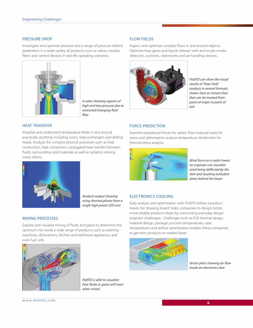
engineering challenges
pressUre DrOp
Investigate and optimize pressure and a range of pressure-related parameters in a wide variety of products such as valves, nozzles, filters and control devices in real-life operating scenarios.
heat transFer
Visualize and understand temperature fields in and around practically anything including ovens, heat exchangers and drilling heads. Analyze the complex physical processes such as heat conduction, heat convection, conjugated heat transfer between fluids, surrounding solid materials as well as radiation among many others.
Mixing prOcesses
Explore and visualize mixing of fluids and gases to determine the optimum mix inside a wide range of products such as washing machines, dishwashers, kitchen and bathroom appliances and even fuel cells.
FlOw FielDs
Inspect and optimize complex flows in and around objects. Optimize how gases and liquids interact with and inside smoke detectors, cyclones, cleanrooms and air-handling devices.
FOrce preDictiOn
Examine operational forces for valves, flow-induced loads for stress and deformation analysis temperature distribution for thermal stress analysis.
electrOnics cOOling
Early analysis and optimization with FloEFD before a product leaves the ‘drawing board’ helps companies to design better, more reliable products faster by overcoming everyday design engineer challenges. Challenges such as PCB thermal design, heatsink design, package junction temperatures, case temperatures and airflow optimization enables these companies to get their products to market faster.
A valve showing regions of high and low pressure due to restricted/changing fluid flow
Analysis output showing rising thermal plume from a single high power LED unit
FloEFD is able to visualize how fluids or gases will react when mixed
FloEFD can show the visual results of ‘Flow Field’ analysis in several formats; shown here as stream lines that can be tracked from point of origin to point of exit
Wind force on a radar tower; an engineer can visualize wind being deflected by the dish and resulting turbulent areas behind the tower
Vector plots showing air flow inside an electronics box
w w w. m ento r.co m7
Aerospace/Defense
Automotive/Transport
Biomedical/Medical
Systems
Chemical/Processing
Computers
Construction/HVAC
Consumer Goods
Electronics
Energy
Lighting
Marine
Oil & Gas
Plastics
Power Generation
Refrigeration
Semiconductors
Telecommunications
Test & Measurement
Valves/Pumps
Water Management
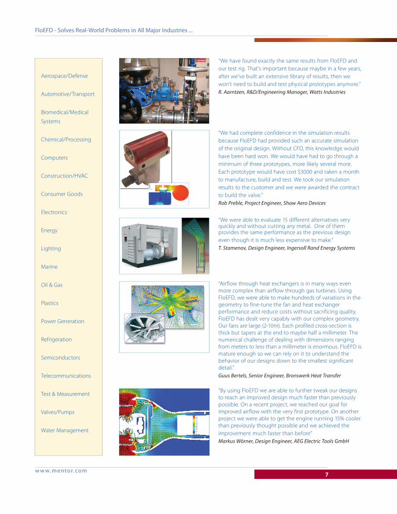
“We have found exactly the same results from FloEFD and our test rig. That’s important because maybe in a few years, after we’ve built an extensive library of results, then we won’t need to build and test physical prototypes anymore.” R. Aarntzen, R&D/Engineering Manager, Watts Industries
“We had complete confidence in the simulation results because FloEFD had provided such an accurate simulation of the original design. Without CFD, this knowledge would have been hard won. We would have had to go through a minimum of three prototypes, more likely several more. Each prototype would have cost $3000 and taken a month to manufacture, build and test. We took our simulation results to the customer and we were awarded the contract to build the valve.” Rob Preble, Project Engineer, Shaw Aero Devices
“We were able to evaluate 15 different alternatives very quickly and without cutting any metal. One of them provides the same performance as the previous design even though it is much less expensive to make.” T. Stamenov, Design Engineer, Ingersoll Rand Energy Systems
“Airflow through heat exchangers is in many ways even more complex than airflow through gas turbines. Using FloEFD, we were able to make hundreds of variations in the geometry to fine-tune the fan and heat exchanger performance and reduce costs without sacrificing quality. FloEFD has dealt very capably with our complex geometry. Our fans are large (2-10m). Each profiled cross-section is thick but tapers at the end to maybe half a millimeter. The numerical challenge of dealing with dimensions ranging from meters to less than a millimeter is enormous. FloEFD is mature enough so we can rely on it to understand the behavior of our designs down to the smallest significant detail.” Guus Bertels, Senior Engineer, Bronswerk Heat Transfer
“By using FloEFD we are able to further tweak our designs to reach an improved design much faster than previously possible. On a recent project, we reached our goal for improved airflow with the very first prototype. On another project we were able to get the engine running 15% cooler than previously thought possible and we achieved the improvement much faster than before” Markus Wörner, Design Engineer, AEG Electric Tools GmbH
FloeFD - solves real-world problems in all Major industries ...
F o r t h e l a t e s t p r o d u c t i n f o r m a t i o n , c a l l u s o r v i s i t : w w w . m e n t o r . c o m©2011 Mentor graphics corporation, all rights reserved. this document contains information that is proprietary to Mentor graphics corporation and may be duplicated in whole or in part by the original recipient for internal business purposes only, provided that this entire notice appears in all copies. in accepting this document, the recipient agrees to make every reasonable effort to prevent unauthorized use of this information. all trademarks mentioned in this document are the trademarks of their respective owners.
Mgc 08-11 1028830-w
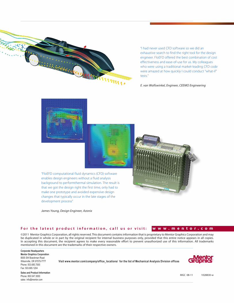
“FloEFD computational fluid dynamics (CFD) software enables design engineers without a fluid analysis background to performthermal simulation. The result is that we got the design right the first time, only had to make one prototype and avoided expensive design changes that typically occur in the late stages of the development process”
James Young, Design Engineer, Azonix
“I had never used CFD software so we did an exhaustive search to find the right tool for the design engineer. FloEFD offered the best combination of cost effectiveness and ease-of-use for us. My colleagues who were using a traditional market-leading CFD code were amazed at how quickly I could conduct “what-if” tests.”
E. van Wolfswinkel, Engineer, CEEMO Engineering