concurrent error detection and...
TRANSCRIPT

International Journal of Advanced Research in Computer Engineering & Technology (IJARCET)
Volume 4 Issue 1, January 2015
159 ISSN: 2278 – 1323 All Rights Reserved © 2015 IJARCET
CONCURRENT ERROR DETECTION AND CORRECTION FOR
ORTHOGONAL LATIN SQUARES ENCODERS AND SYNDROME
COMPUTATION
1S.SANTHOSH KUMAR
1 IV-YEAR , ECE STUDENT , Vidya Jyothi Institute of Technology, Hyderabad
ABSTRACT: In advanced electronic circuits the reliability has been a major concern. There are number of mitigation
techniques proposed to make sure that the errors do not affect the circuit functionality. Among them, to protect the memories
and registers in electronic circuits Error Correction Codes (ECC) are commonly used. Whenever any ECC technique is used,
the encoder and decoder circuit may also suffer errors. In this brief, concurrent error detection and correction technique for
OLS encoders and syndrome computation is proposed and evaluated. The proposed method efficiently implements a parity
prediction scheme that detects all errors that affect a single circuit node using the properties of OLS codes. The results
constitute simulation of Verilog codes of different modules of the codes in Xilinx 13.2. The results demonstrate that the CED
for OLS encoders & Syndrome Computation are very efficient for the detection and correction of burst errors.
Keywords: Error Correction Codes,Ols Codes,Ced,Ols
1. INTRODUCTION:
In the early days of computers, the failures due to
transient or intermittent faults were an accepted way of life.
Since then, as computers are more relied upon and as are
being used in the design of numerous systems, such failures
are no longer acceptable, especially in the case of critical
systems. The most sensitive part in computers is the
semiconductor memory which is susceptible to both, hard and
soft faults. The memory faults are caused by the high-energy
subatomic particles, commonly known as cosmic rays. These
splinters of shattered nuclei have been bombarding the planet
from all directions, but computer scientists did not pay them
any heed until the late 1970s, when memory bits get small
enough to be affected by the supersonic alpha particles that
can flip a bit from 1 to 0 or 0 to 1. The errors in the memory
are being successfully dealt with ECC
As computing and communications become
irreplaceable tools of modern era, one fundamental principle
emerges: The greater the benefits these systems bring, the
greater the potential for harm when they fail to perform their
functions or perform them incorrectly. High density of chips
have inevitably caused unpredictable system behavior and
increased the potential for multiple faults originating from a
single source. Most of the systems (whether critical or non-
critical) being designed these days are computer-controlled.
Critical systems must contain highly reliable semiconductor
memories. The computations, on which the functionality of a
critical system depends, may be frequently required to store in
such memories. Even a single bit error can affect the whole
computations and can subsequently cause a system’s failure
which in turn may cause catastrophes. This opens the way to
develop “Fault Tolerant Memories”.
Errors in general are categorizes into “Logic Errors”
and “Memory Errors”. The former is generally permanent in
nature, which may occur anywhere in the hardware including
processors and memories. By “Memory Errors”, we normally
mean the soft errors, caused due to many reasons.
According to a survey and research, the following
factors have a direct impact on error rates:
Increased complexity raises the error rate.
Higher-density (higher-capacity) chips are more likely to
have errors.
Lower-voltage devices are more likely to have errors.
Higher speeds (lower latencies) contribute to higher error
rates.
Lower cell capacitance (less storage charge) causes
higher error rates.
Shorter bit-lines result in few errors.
Wafer thinning improves error tolerance.
“Radiation Hardening” can decrease error rates but
several orders of magnitude, but these techniques cost
more, reduce performance, use more power, and/or
increase area.
This paper is confined to memory errors, as these are
most dominant over the other errors. Any small to large
systems such as super-computers and cell phones to video
games, contain memory, most often RAM. Reliability of
RAM during working is one of a key element in many
applications. The RAM chips may undergo physical defects
during various stages of its fabrication, including silicon
crystal formation, oxidation, diffusion, optical lithography,
metallization and packaging. If it is produced defect-free, still
it can get defects or permanent faults during its working life.
Such faults are called hard memory faults. The most common
results of defects are faulty logic or flaky connections which
usually manifest as opens, shorts or stuck at 1 or 0.

International Journal of Advanced Research in Computer Engineering & Technology (IJARCET)
Volume 4 Issue 1, January 2015
160 ISSN: 2278 – 1323 All Rights Reserved © 2015 IJARCET
Semiconductor memories are more susceptible to
transient-faults (the faults which appear and disappear) due to
impingement of alpha particles, electrostatic discharges,
glitches, etc. among them alpha particles are the most
prominent one. In fact, DRAM chips can be exploited as
reliable and cheap alpha particle detectors. The intermittent-
faults (the faults which appear, disappear and reappear) can
occur due to resistance and capacitance variations and
coupling effects. The transient and intermittent faults cause to
generate soft memory errors. A soft memory error is defined
as a random event that corrupt the value stored in the memory
cell without damaging the cell itself. Such errors are being
successfully dealt with ECC, which has gained a tremendous
impetus during the recent past.
A memory can be made fault-tolerant with the
application of an error-correcting code, such as Hamming
code, Reed-Muller code, the proposed OLS codes, etc. the
mean time between “failures” of a properly designed memory
system can be significantly increased with an error-correcting
code. In this respect, a system “fails” only when the errors
exceed the error-correcting capability of the code. Also, in
order to optimize data integrity, the error correcting code
should have the capability of detecting the most likely of the
errors that are uncorrectable.
This paper presents the OLS scheme to deal with the
memory errors, mostly with specific to the critical systems.
The techniques have been developed independently and
present unique characteristics and advantages. This technique
makes use of the hardware and information redundancies
simultaneously in the design, which might not present the cost
effective solution, but since such techniques are mainly
targeted for critical systems, the cost becomes the secondary
factor. Employing ECC with the memories, generally
increases the cost between 10% to 20%, typically increases
the die-area around 20% and may also slow down the speed
around 3-4%, but the advantages obtained in terms of
reliability and accuracy are incomparable.
2. CONCURRENT ERROR DETECTION SCHEMES:
2.1 TYPES OF ERROR DETECTION SCHEMES
Schemes for Error Detection find wide range of
applications, since only after the detection of error, can any
preventive measure be initiated. The principle of error
detecting scheme is very simple, an encoded codeword needs
to preserve some characteristic of that particular scheme, and
a violation is an indication of the occurrence of an error. Some
of the error detection techniques are discussed below.
2.1.1 Parity Codes: These are the simplest form of error detecting codes,
with a hamming distance of two (d=2), and a single check bit
(irrespective of the size of input data). They are of two basic
types: Odd and Even. For an even-parity code the check bit is
defined so that the total number of 1s in the code word is
always even; for an odd code, this total is odd. So, whenever a
fault affects a single bit, the total count gets altered and hence
the fault gets easily detected. A major drawback of these
codes is that their multiple fault detection capabilities are very
limited.
2.1.2 Checksum Codes: In these codes the summation of all the information
bytes is appended to the information as bit checksum. Any
error in the transmission will be indicated as a resulting error
in the checksum. This leads to detection of the error. When
b=1, these codes are reduced to parity check codes. The codes
are systematic in nature and require simple hardware units.
2.1.3 m-out-of-n Codes: In this scheme the codeword is of a standard weight
m and standard length n bits. Whenever an error occurs during
transmission, the weight of the code word changes and the
error gets detected. If the error is a 0 to 1 transition an increase
in weight is detected, similarly 1 to 0 leads to a reduction in
weight of the code, leading to easy detection of error. This
scheme can be used for detection of unidirectional errors,
which are the most common form of error in digital systems.
2.1.4Berger Codes:
Berger codes are systematic unidirectional error
detecting codes. They can be considered as an extension of the
parity codes. Parity codes have one check bit, which can be
considered as the number of information bits of value 1
considered in modulo2. On the other hand Berger codes have
enough check bits to represent the count of the information
bits having value 0. The number of check bits (r) required for
k-bit information is given by
r = [log2 (k − 1)]
Of all the unidirectional error detecting codes that
exist suggests, m-out of-n codes to be the most optimal. These
codes however, are not of much application because of its non
separable nature. Amongst the separable codes in use, the
Berger codes have been proven to be most optimal, requiring
the smallest number of check bits.The Berger Codes,
however, are not optimal when only t unidirectional errors
need to be detected instead of all unidirectional errors. For this
reason a number of different modified Berger codes exist: Hao
Dong introduced a code that accepts slightly reduced error
detection capabilities, but does so using fewer check bits and
smaller checker sizes. In this code the number of check bits is
independent of the number of information bits. Bose and Lin
have introduced their own variation on Berger codes and Bose
has further introduced a code that improves on the burst error
detection capabilities of his previous code, where erroneous
bit are expected to appear in groups.
3.DIFFERENT TYPES OF CONCURRENT ERROR
DETECTION SCHEMES:
Concurrent Error Detection (CED) techniques are
widely used to enhance system dependability. Almost all CED
techniques function according to the following principle: Let
us suppose that the system under consideration realizes a
International Journal of Advanced Research in Computer Engineering & Technology (IJARCET)
Volume 4 Issue 1, January 2015
161 ISSN: 2278 – 1323 All Rights Reserved © 2015 IJARCET
function f and produces output f(i) in response to an input
sequence i.
A CED scheme generally contains another unit which
independently predicts some special characteristic of the
system-output f(i) for every input sequence i. Finally, a
checker unit checks whether the special characteristic of the
output actually produced by the system in response to input
sequence i is the same as the one predicted and produces an
error signal when a mismatch occurs. Some examples of the
characteristics of f(i) are: f(i) itself, its parity, 1’s count, 0’s
count, transition count, etc.
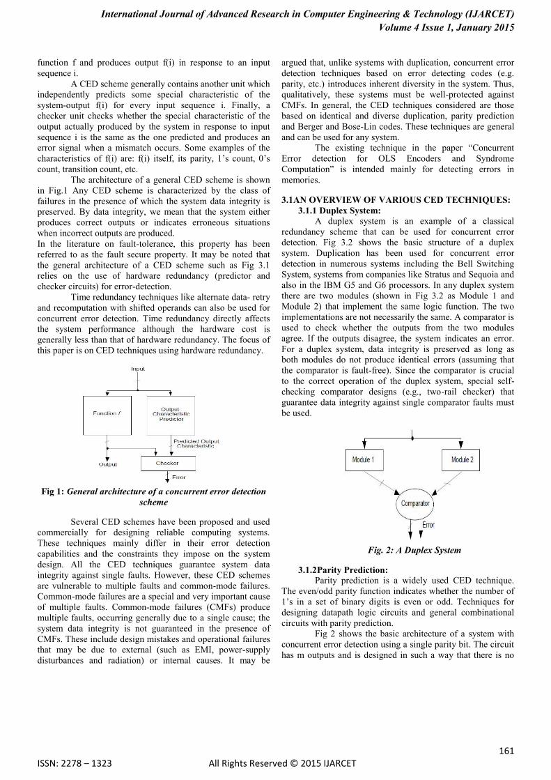
The architecture of a general CED scheme is shown
in Fig.1 Any CED scheme is characterized by the class of
failures in the presence of which the system data integrity is
preserved. By data integrity, we mean that the system either
produces correct outputs or indicates erroneous situations
when incorrect outputs are produced.
In the literature on fault-tolerance, this property has been
referred to as the fault secure property. It may be noted that
the general architecture of a CED scheme such as Fig 3.1
relies on the use of hardware redundancy (predictor and
checker circuits) for error-detection.
Time redundancy techniques like alternate data- retry
and recomputation with shifted operands can also be used for
concurrent error detection. Time redundancy directly affects
the system performance although the hardware cost is
generally less than that of hardware redundancy. The focus of
this paper is on CED techniques using hardware redundancy.
Fig 1: General architecture of a concurrent error detection
scheme
Several CED schemes have been proposed and used
commercially for designing reliable computing systems.
These techniques mainly differ in their error detection
capabilities and the constraints they impose on the system
design. All the CED techniques guarantee system data
integrity against single faults. However, these CED schemes
are vulnerable to multiple faults and common-mode failures.
Common-mode failures are a special and very important cause
of multiple faults. Common-mode failures (CMFs) produce
multiple faults, occurring generally due to a single cause; the
system data integrity is not guaranteed in the presence of
CMFs. These include design mistakes and operational failures
that may be due to external (such as EMI, power-supply
disturbances and radiation) or internal causes. It may be
argued that, unlike systems with duplication, concurrent error
detection techniques based on error detecting codes (e.g.
parity, etc.) introduces inherent diversity in the system. Thus,
qualitatively, these systems must be well-protected against
CMFs. In general, the CED techniques considered are those
based on identical and diverse duplication, parity prediction
and Berger and Bose-Lin codes. These techniques are general
and can be used for any system.
The existing technique in the paper “Concurrent
Error detection for OLS Encoders and Syndrome
Computation” is intended mainly for detecting errors in
memories.
3.1AN OVERVIEW OF VARIOUS CED TECHNIQUES:
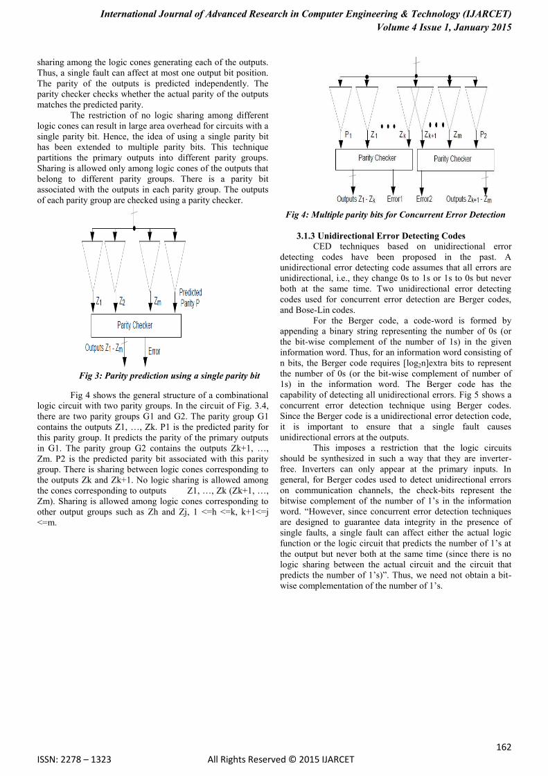
3.1.1 Duplex System:
A duplex system is an example of a classical
redundancy scheme that can be used for concurrent error
detection. Fig 3.2 shows the basic structure of a duplex
system. Duplication has been used for concurrent error
detection in numerous systems including the Bell Switching
System, systems from companies like Stratus and Sequoia and
also in the IBM G5 and G6 processors. In any duplex system
there are two modules (shown in Fig 3.2 as Module 1 and
Module 2) that implement the same logic function. The two
implementations are not necessarily the same. A comparator is
used to check whether the outputs from the two modules
agree. If the outputs disagree, the system indicates an error.
For a duplex system, data integrity is preserved as long as
both modules do not produce identical errors (assuming that
the comparator is fault-free). Since the comparator is crucial
to the correct operation of the duplex system, special self-
checking comparator designs (e.g., two-rail checker) that
guarantee data integrity against single comparator faults must
be used.
Fig. 2: A Duplex System
3.1.2Parity Prediction: Parity prediction is a widely used CED technique.
The even/odd parity function indicates whether the number of
1’s in a set of binary digits is even or odd. Techniques for
designing datapath logic circuits and general combinational
circuits with parity prediction.
Fig 2 shows the basic architecture of a system with
concurrent error detection using a single parity bit. The circuit
has m outputs and is designed in such a way that there is no
International Journal of Advanced Research in Computer Engineering & Technology (IJARCET)
Volume 4 Issue 1, January 2015
162 ISSN: 2278 – 1323 All Rights Reserved © 2015 IJARCET
sharing among the logic cones generating each of the outputs.
Thus, a single fault can affect at most one output bit position.
The parity of the outputs is predicted independently. The
parity checker checks whether the actual parity of the outputs
matches the predicted parity.
The restriction of no logic sharing among different
logic cones can result in large area overhead for circuits with a
single parity bit. Hence, the idea of using a single parity bit
has been extended to multiple parity bits. This technique
partitions the primary outputs into different parity groups.
Sharing is allowed only among logic cones of the outputs that
belong to different parity groups. There is a parity bit
associated with the outputs in each parity group. The outputs
of each parity group are checked using a parity checker.
Fig 3: Parity prediction using a single parity bit
Fig 4 shows the general structure of a combinational
logic circuit with two parity groups. In the circuit of Fig. 3.4,
there are two parity groups G1 and G2. The parity group G1
contains the outputs Z1, …, Zk. P1 is the predicted parity for
this parity group. It predicts the parity of the primary outputs
in G1. The parity group G2 contains the outputs Zk+1, …,
Zm. P2 is the predicted parity bit associated with this parity
group. There is sharing between logic cones corresponding to
the outputs Zk and Zk+1. No logic sharing is allowed among
the cones corresponding to outputs Z1, …, Zk (Zk+1, …,
Zm). Sharing is allowed among logic cones corresponding to
other output groups such as Zh and Zj, 1 <=h <=k, k+1<=j
<=m.
Fig 4: Multiple parity bits for Concurrent Error Detection
3.1.3 Unidirectional Error Detecting Codes
CED techniques based on unidirectional error
detecting codes have been proposed in the past. A
unidirectional error detecting code assumes that all errors are
unidirectional, i.e., they change 0s to 1s or 1s to 0s but never
both at the same time. Two unidirectional error detecting
codes used for concurrent error detection are Berger codes,
and Bose-Lin codes.
For the Berger code, a code-word is formed by
appending a binary string representing the number of 0s (or
the bit-wise complement of the number of 1s) in the given
information word. Thus, for an information word consisting of
n bits, the Berger code requires [log2n]extra bits to represent
the number of 0s (or the bit-wise complement of number of
1s) in the information word. The Berger code has the
capability of detecting all unidirectional errors. Fig 5 shows a
concurrent error detection technique using Berger codes.
Since the Berger code is a unidirectional error detection code,
it is important to ensure that a single fault causes
unidirectional errors at the outputs.
This imposes a restriction that the logic circuits
should be synthesized in such a way that they are inverter-
free. Inverters can only appear at the primary inputs. In
general, for Berger codes used to detect unidirectional errors
on communication channels, the check-bits represent the
bitwise complement of the number of 1’s in the information
word. “However, since concurrent error detection techniques
are designed to guarantee data integrity in the presence of
single faults, a single fault can affect either the actual logic
function or the logic circuit that predicts the number of 1’s at
the output but never both at the same time (since there is no
logic sharing between the actual circuit and the circuit that
predicts the number of 1’s)”. Thus, we need not obtain a bit-
wise complementation of the number of 1’s.

International Journal of Advanced Research in Computer Engineering & Technology (IJARCET)
Volume 4 Issue 1, January 2015
163 ISSN: 2278 – 1323 All Rights Reserved © 2015 IJARCET
F
ig 5: Concurrent Error Detection Using Berger Codes Bose-Lin codes are capable of detecting t-bit
unidirectional errors in the code-word. Design of logic circuits
with concurrent error detection based on Bose-Lin codes has
been reported in Fig 3.6 shows the architecture of a system
with concurrent error detection based on 2-bit unidirectional
error detecting Bose-Lin code. Just like Berger codes, we
want the circuit to be inverter-free (except at the primary
inputs), so that any single fault creates unidirectional errors at
the outputs.
Fig 6: Concurrent Error detection using Bose-Lin codes
We also need a restriction on the amount of logic sharing
since the code is capable of detecting at most 2 unidirectional
errors. The restriction is that, any logic gate in the circuit can
be shared by the logic cones of at most two primary outputs.
4. ORTHOGONAL LATIN SQUARE SCHEME:
An ideal ECC is one that results in a high speed and a
simple decoding circuit, but speed and redundancy do not go
together, in fact these are inversely related to each other,
which means with low-redundancy, the design of a decoder is
likely to be complex.
Generally ECC is associated with two types of
redundancies, i.e., Hardware Redundancy and Information
Redundancy. Both of these redundancies are themselves
related inversely to each other, which means if the information
redundancy is increased in a given code without aiming to
enhance its error correcting capability then it will require less
hardware and will result in an efficient decoder circuit. The
reason is that high information redundancy results in low-
density parity check equations, which enable us to get fast and
inexpensive circuits. The LSCs (Latin Square Codes) are the
one which have the above attribute and not only this, but the
hardware is also convenient to develop through modular
approach. As far as the information redundancy is concerned,
it cannot be increased or decreased at will. It is governed by
lower and upper bounds on "r", known as Hamming and
Gilbert bounds respectively. The technique based on using the
LSCs, has remained in the theory for a long time. The initial
work on LSCs can be found in an old research done at IBM
research & development division. Such work remained in
theory for a long time.
For general applications, simple SEC codes were
considered enough and the requirement of MEC code ceases
to exist. Moreover, the past technologies were not supportive
to develop a large and complex decoder. But now, SEC and
MEC codes have got much attention due to the high
complexity and high speed of the current technology.
4.1 ADVANTAGES & CHARACTERISTICS OF LSCS:
The LSCs have some unique characteristics as follows:
The redundancy can be added systematically and
through a modular approach for enhancing the capability
of the codes. Thus moving from 1-bit error correction
capability to 2-bit error correction capability, we just need
to extend the existing hardware without changing the
existing circuit. Hence these codes are ideal for multiple
error corrections and provide design simplicity.
These codes are one-step-decodable majority codes,
providing the fastest parallel decoding.
These codes are self-orthogonal and non-cyclic.
The parity-check matrix possesses a uniform pattern
and results in a small number of inputs to modulo 2
adders (XOR gates).
For rn2 data bits, 2tm information overheads are
required. Hence for 4- information bits (k), 4 extra bits
(redundant bits) are required for 1-bit correction, which
means the code represents. (8, 4) code. Clearly, the
overhead percentage decreases as the "k" increases, as
obvious from the table 4.1.
From implementation point of view, exactly 2tm check
bit equations can be obtained from the relevant H-matrix,
but we normally implement 2t equations.
i.e., only those equations related to correct the data bits
(k) only.
TABLE 4.1
DATA BITS VERSUS OVER-HEAD
REQUIREMENTS

International Journal of Advanced Research in Computer Engineering & Technology (IJARCET)
Volume 4 Issue 1, January 2015
164 ISSN: 2278 – 1323 All Rights Reserved © 2015 IJARCET
4.2 INTRODUCTION TO OLS SCHEME:
Error correction codes (ECCs) have been used to
protect memories for many years. There is a wide range of
codes that are used or have been proposed for memory
applications. Single error correction (SEC) codes that can
correct one bit per word are commonly used. More advanced
codes that can also correct double adjacent errors or double
errors in general have also been studied. The use of more
complex codes that can correct more errors is limited by their
impact on delay and power, which can limit their applicability
to memory designs. To overcome those issues, the use of
codes that are one step majority logic decodable (OS-MLD)
has recently been proposed.
OS-MLD codes can be decoded with low latency and
are, therefore, used to protect memories. Among the codes
that are OS-MLD, a type of Euclidean geometry (EG) code
has been proposed to protect memories. Another type of code
that is OS-MLD is orthogonal Latin squares (OLS) code.
The use of OLS codes has gained renewed interest
for interconnections, memories, and caches. This is due to
their modularity such that the error correction capabilities can
be easily adapted to the error rate or to the mode of operation.
OLS codes typically require more parity bits than other codes
to correct the same number of errors. However, their
modularity and the simple and low delay decoding
implementation (as OLS codes are OS-MLD), offset this
disadvantage in many applications.
An important issue is that the encoder and decoder
circuits needed to use (ECCs) can also suffer errors. When an
error affects the encoder, an incorrect word may be written
into the memory. An error in the decoder can cause a correct
word to be interpreted as erroneous or the other way around,
an incorrect word to be interpreted as a correct word.
The protection of the encoders and decoders has been
studied for different ECCs. For example, in EG codes were
studied. The protection of Reed–Solomon, Hamming, and
BCH encoders and decoders has also been studied.
The ECC encoder computes the parity bits, and in
most cases the decoder starts by checking the parity bits to
detect errors. This is commonly referred to as syndrome
computation. For some codes, it is possible to perform
encoding and syndrome computation serially based on the
properties of the code. However, when delay has to be low,
parallel implementations are preferred. This is the case for
OLS codes that are commonly used in high-speed
applications. The reader is referred to for a detailed discussion
of ECC encoders and decoders. After syndrome computation,
when errors are detected, the rest of the decoding is done to
correct the errors. This means that generating and checking
the parity bits are important parts of the encoder and decoder
circuitry. Therefore, its protection is an important issue.
In this brief, the protection of the encoders and
syndrome computation for OLS codes when used in SRAM
memories and caches is considered. Based on the specific
properties of these codes, it is shown that parity prediction is
an effective technique to detect errors in the encoder and
syndrome computation. This is not the case for most other
block codes for which parity prediction cannot provide
effective protection. Therefore, this is another advantage of
OLS codes in addition to their modularity and simple
decoding.
4.3 ORTHOGONAL LATIN SQUARES:
OLS codes are based on the concept of Latin squares.
A Latin square of size m is an m × m matrix that has
permutations of the digits 0, 1… m − 1 in both its rows and
columns. Two Latin squares are orthogonal if when they are
superimposed every ordered pair of elements appears only
once. OLS codes are derived from OLS. These codes have k =
m2 data bits and 2tm check bits, where t is the number of
errors that the code can correct. For a double error correction
code t = 2, and, therefore, 4m check bits, are used. As
mentioned in the introduction, one advantage of OLS codes is
that their construction is modular. This means that to obtain a
code that can correct t+1 errors, simply 2m check bits are
added to the code that can correct t errors. This can be useful
to implement adaptive error correction schemes. The modular
property also enables the selection of the error correction
capability for a given word size.
As mentioned before, OLS codes can be decoded
using OS-MLD as each data bit participates in exactly 2t
check bits and each other bit participates in at most one of
those check bits. This enables a simple correction when the
number of bits in error is t or less. The 2t check bits are
recomputed and a majority vote is taken. If a value of one is
obtained, the bit is in error and must be corrected. Otherwise
the bit is correct. As long as the number of errors is t or less,
the remaining t −1 errors can, in the worst case, affect t −1
check bits. Therefore, still a majority of t + 1 triggers the
correction of an erroneous bit. In any case, the decoding starts
by recomputing the parity check bits and checking against the
stored parity check bits.
The parity check matrix H for OLS codes is
constructed from the OLS. As an example, the matrix for a
code with k = 16 and 8 check bits that can correct single errors
is shown in Fig. 5.1. As discussed earlier, due to the modular
construction of OLS codes this matrix forms part of the H
matrix for codes that can correct more errors. For example, to
obtain a code that can correct two errors, eight additional rows

International Journal of Advanced Research in Computer Engineering & Technology (IJARCET)
Volume 4 Issue 1, January 2015
165 ISSN: 2278 – 1323 All Rights Reserved © 2015 IJARCET
are added to the H matrix. For an arbitrary value of k = m2, the
H matrix for a SEC- OLS code is constructed as follows:
Fig 7: Generalized H matrix of Latin square code
for SEC
Where I2tm is the identity matrix of size 2m and M1, M2 are
matrices of size m × m2. The matrixes M1 AND M2 have the
following forms:
Fig 8 : General form of Sub-matrix M1
M2= [Im Im …..Im] i.e., all are identity matrices of order m.
In summary, the encoder takes k = m2 data bits (di)
and computes 2tm parity check bits (ci) using a matrix G,
which is derived from Latin squares and has the following
properties.
1) Each data bit participates exactly in 2t parity checks.
2) A pair of data bits participates (both bits) in at most one of
the parity checks.
5. PROPOSED CONCURRENT ERROR DETECTION &
CORRECTION TECHNIQUE:
5.1 EXISTING METHOD (CED FOR OLS)
Before describing the proposed error detection
technique, the standard definition of self-checking circuits that
are used in this section is presented. During normal, or fault-
free, operation, a circuit receives only a subset of the input
space, called the input code space, and produces a subset of
the output space, called the output code space. The outputs
that are not members of the output code space form the output
error space. In general, a circuit may be designed to be self-
checking only for an assumed fault set. In this brief, we
consider the fault set F corresponding to the single stuck-at
fault model.
A circuit is self-checking if and only if it satisfies the
following properties:
1) It is self-testing, and 2) fault-secure.
A circuit is self-testing if, for each fault f in the fault
set F, there is at least one input belonging to the input code
space, for which the circuit provides an output belonging to
the output error space. A circuit is fault-secure if, for each
fault f in the fault set F and for each input belonging to the
input code space, the circuit provides the correct output, or an
output belonging to the output error space.
The fault-secure property guarantees that the circuit
gives the correct response, or signals the presence of a fault
that provides an output in the error space. Faults are always
detected, since there is an input that produces an output that
identifies the presence of the fault.
This property is related to the assumption that the
interval between the occurrences of two faults is enough to
permit to all the elements belonging to the input code space to
appear as circuit inputs before the occurrence of the second
fault. Thus, an output belonging to the output error space
appears at the circuit output before the occurrence of the
second fault.
Fig 9: Parity check matrix for OLS code with k = 16
and t = 1
The error detection technique is based on the use of
parity prediction, which is one of the techniques that are used
to detect and correct error in typical logic circuits. In our case,
the problem is much simpler, given the structure of the OLS
codes. For an encoder, the proposed is that the parity of the
calculated check bits (ci) is set against the parity of all the
check equations. The equation obtained by calculating the
parity of the columns in G is simply the parity of all check
equations. Since for OLS codes, each column in G will have
exactly 2t ones, so null equation is obtained (see, for example,
Fig 5.1). Therefore, the concurrent error detection (CED) is
normally to check
c1 ⊕ c2 ⊕ c3 ⊕・ ・ ・⊕c2tm = 0 (1)
r1 ⊕ r2 = 0 (2)
This enables an efficient implementation that is not
possible in other codes. For example, in a Hamming code a
significant part of the columns in G has an odd weight and for
some codes the number is even larger as they are designed to
have odd weights. The input code space of the OLS encoder
corresponds to the input space, since the encoder can receive
all the possible 2k input configurations. The output code space
of the OLS encoder is composed by the outputs satisfying
eq(1) and eq(2), while the output error space is the
complement of the output code space.
A fault that occurs in one of the gates composing the
OLS encoder can change at most one of the ci check bits.
When this change occurs, the OLS encoder provides an output
that does not satisfy (1) and (2), i.e., an output belonging to
the output error space. Hence, this guarantees the fault-secure
property for this circuit. Additionally, since the encoder is
composed only by XOR gates, no logic masking is performed
in the circuit. Therefore, when a fault is activated the error is
propagated to the output. This ensures the self-testing property
International Journal of Advanced Research in Computer Engineering & Technology (IJARCET)
Volume 4 Issue 1, January 2015
166 ISSN: 2278 – 1323 All Rights Reserved © 2015 IJARCET
of the circuit. In order to check if the output of the OLS
encoder belongs to the output code space or the output error
space, a self-checking implementation of a parity checker is
used. The checker controls the parity of its inputs and is
realized with a repetition code. The two outputs (r1, r2) are
each equal to the parity of one of two disjoint subsets of the
checker inputs (ci). When a set of inputs with the correct
parity is provided, the output code (r1, r2) takes the values 00
or 11 and are compared against checker to get to know that the
output is error free.
When the checker receives an erroneous set of inputs,
the checker provides the output codes 01 or 10 and the output
would e would be 1. Also, if a fault occurs in the checker, the
outputs are 01 or 10 and so the output e=1. This guarantees
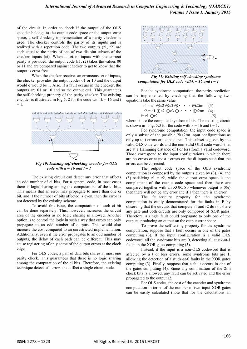
the self-checking property of the parity checker. The existing
encoder is illustrated in Fig 5. 2 for the code with k = 16 and t
= 1.
Fig 10: Existing self-checking encoder for OLS
code with k = 16 and t = 1
The existing circuit can detect any error that affects
an odd number of ci bits. For a general code, in most cases
there is logic sharing among the computations of the ci bits.
This means that an error may propagate to more than one ci
bit, and if the number of bits affected is even, then the error is
not detected by the existing scheme.
To avoid this issue, the computation of each ci bit
can be done separately. This, however, increases the circuit
area of the encoder as no logic sharing is allowed. Another
option is to control the logic in such a way that errors can only
propagate to an odd number of outputs. This would also
increase the cost compared to an unrestricted implementation.
Additionally, even if the error propagates to an odd number of
outputs, the delay of each path can be different. This may
cause registering of only some of the output errors at the clock
edge.
For OLS codes, a pair of data bits shares at most one
parity check. This guarantees that there is no logic sharing
among the computation of the ci bits. Therefore, the existing
technique detects all errors that affect a single circuit node.
Fig 11: Existing self-checking syndrome
computation for OLS code withk = 16 and t = 1
For the syndrome computation, the parity prediction
can be implemented by checking that the following two
equations take the same value
r1 = s1 ⊕ s2 ⊕ s3 ⊕・ ・ ・⊕s2tm (3)
r2 = c1 ⊕ c2 ⊕ c3 ⊕ ・・ ・⊕c2tm (4)
f= r1 ⊕ r2 (5)
where si are the computed syndrome bits. The existing circuit
is shown in Fig. 5.3 for the code with k = 16 and t = 1.
For syndrome computation, the input code space is
only a subset of the possible 2k+2tm input configurations as
only up to t errors are considered. This subset is given by the
valid OLS code words and the non-valid OLS code words that
are at a Hamming distance of t or less from a valid codeword.
Those correspond to the input configurations in which there
are no errors or at most t errors on the di inputs such that the
errors can be corrected.
The output code space of the OLS syndrome
computation is composed by the outputs given by (3), (4) and
(5) satisfying r1 = r2, while the output error space is the
complement of the output code space and then these are
compared together with an XOR. So whenever output is 0(e)
then there will not be any error and if 1 then there is an error.
The fault-secure property for the syndrome
computation is easily demonstrated for the faults in F by
observing that the circuits that compute r1 and r2 do not share
any gate and both circuits are only composed of XOR gates.
Therefore, a single fault could propagate to only one of the
outputs, producing an output on the output error space.
To prove the self-testing property for the syndrome
computation, suppose that a fault occurs in one of the gates
computing (3). If the input configuration is a valid OLS
codeword, all the syndrome bits are 0, detecting all stuck-at-1
faults in the XOR gates computing (3).
Instead, if the input is a non-OLS codeword that is
affected by a t or less errors, some syndrome bits are 1,
allowing the detection of a stuck-at-0 faults in the XOR gates
computing (3). Finally, suppose that a fault occurs in one of
the gates computing (4). Since any combination of the 2tm
check bits is allowed, any fault can be activated and the error
propagated to the output r2.
For OLS codes, the cost of the encoder and syndrome
computation in terms of the number of two-input XOR gates
can be easily calculated (note that for the calculations an

International Journal of Advanced Research in Computer Engineering & Technology (IJARCET)
Volume 4 Issue 1, January 2015
167 ISSN: 2278 – 1323 All Rights Reserved © 2015 IJARCET
l−input XOR gate is assumed to be equivalent to l − 1 two-
input XOR gates). For a code with k = m2 and that can correct
t errors, there are 2tm parity check bits and the computation of
each of them requires m − 1 two input XOR gates. Therefore,
the encoder requires 2tm (m − 1) two-input XOR gates. For
the syndrome computation, an additional XOR gate is needed
for each parity check bit, giving a total of 2tm2 two-input
XOR gates. The existing method requires 2tm−1 two-input
XOR gates for the encoder and 4tm-2 two-input XOR gates
for the syndrome computation. This means that the overhead
required to implement our method for the encoder is
Oencoder = (2tm-1) (6)
(2tm (m-1))
and for the syndrome computation it is
Osyndrome = (4tm-2) (7)
(2tm2)
TABLE 5.1
OVERHEAD OF PROPOSED CED FOR SEC-OLS CODES
k m Encoder Syndrome
16 4 29.17% 87.50%
64 8 13.39% 46.87%
256 16 12.91% 24.21%
For large values of m, the first equation can be
approximated by 1/m and the second by 2/m. This shows that
as the block size of the code k = m2 grows, the overhead
becomes smaller and independent of t. This is illustrated in
Table 5.1, where the overheads predicted by eq(6) and eq(7)
are illustrated for t = 1 and different values of k. The overhead
in terms of delay is significant as the proposed parity
computation is done over the results of the encoder or
syndrome computation. This means that the delay of the new
logic adds directly to the encoding or syndrome computation
delay. However, the effect on the memory access time can be
minimized by noting that for the encoder the error checking
can be done in parallel with the writing of the data into the
memory. Then if an error is detected, the data is encoded and
written again. For the syndrome computation, the error
detection can be performed in parallel with the majority logic
voting and the error correction such that again, the impact on
access time is minimized.
5.2 PROPOSED METHOD:
As discussed in Chapter 2 regarding different types
of Concurrent techniques. Here parity prediction scheme is
used for this method.
The proposed method is very similar to the existing
method, here we are going to duplicate and calculate the check
bits for the circuit without CED technique for both encoder
and syndrome computation circuits and then compare them
with the check bits of CED circuit.
5.2.1CCD ENCODER:
Fig. 12: Proposed self-checking & correction encoder for
OLS code withk = 16 and t = 1
For correction of the errors in the encoder, first the
circuit is partially duplicated till the generation of check bits
by giving the same input combinations. Then the check
bits(cj) of the duplicated circuit are compared against the
check bits(ci) of the original (CED) circuit by using the 2X1
multiplexer, where the original circuit check bits (ci) are
connected to the first input while the check bits (cj) obtained
from duplicated circuit are connected to the second input of
multiplexer and the selection bit for that is given from the
output(e) of the original circuit, whenever the selection bit is
0, then the original circuit is selected and if it is not equal to 0
then the duplicated circuit gets selected.
c_output=e~(ci)+e(cj) (8)
where ci are the check bits of the original circuit and cj
represents the check bits of the duplicated circuit.
This gives an efficient implementation which is not
possible in other ECC codes. For example, in the Hamming
code a major part of the columns in G have an odd weight and
for some different codes the number is even larger as they are
designed to have odd weights and also in that codes we need
to correct the codes manually, but in this case the codes are
automatically corrected.
The input code space of the OLS encoder corresponds to
the input space, since the encoder can receive all the possible
2k input configurations. The output code space of the OLS
encoder is composed by the outputs satisfying (1), (2) and (8),
while the output error space is the complement of the output
code space.
In order to check whether the output of the OLS encoder
belongs to the output code space or the output error space, a
self-checking implementation of a parity checker is used. The
checker and correction unit controls the parity of its inputs and
is realized with a repetition code. The two outputs (r1, r2) are
each equal to the parity of one of two disjoint subsets of the
checker inputs (ci). When a set of inputs with the correct
parity is provided, the output code {r1, r2} takes the values 00
or 11 and the two bits are compared against each other using a
checker to get the output 0. When the checker receives an
erroneous set of inputs, the checker provides the output codes
International Journal of Advanced Research in Computer Engineering & Technology (IJARCET)
Volume 4 Issue 1, January 2015
168 ISSN: 2278 – 1323 All Rights Reserved © 2015 IJARCET
01 or 10 and so the output checker e will be equal to 1. Also,
if a fault occurs in the checker, the outputs are 01 or 10 and
the final checker output will be 1. This guarantees the self-
checking property of the parity checker. The proposed encoder
is illustrated in Fig. 5.4 for the code with k = 16 and t = 1.
For correction of the errors in the encoder, first the circuit
is partially duplicated till the generation of check bits by
giving the same input combinations. Then the check bits(cj) of
the duplicated circuit are compared against the check bits(ci)
of the original (CED) circuit by using the 2X1 multiplexer,
where the original circuit check bits (ci) are connected to the
first input while the check bits (cj) obtained from duplicated
circuit are connected to the second input of multiplexer and
the selection bit for that is given from the output(e) of the
original circuit, whenever the selection bit is 0, then the
original circuit is selected and if it is not equal to 0 then the
duplicated circuit gets selected.
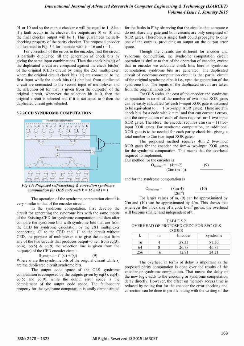
5.2.2CCD SYNDROME COMPUTATION:
Fig 13: Proposed self-checking & correction syndrome
computation for OLS code with k = 16 and t = 1
The operation of the syndrome computation circuit is
very similar to that of the encoder circuit.
In the syndrome computation, first develop the
circuit for generating the syndrome bits with the same inputs
of the Existing CED for syndrome computation and then after
compare the syndrome bits with syndrome bits that are from
the CED for syndrome calculation by the 2X1 multiplexer
connecting “0” to the CED and “1” to the circuit without
CED, the purpose of multiplexer is to give the output from
any of the two circuits that produces output=0 i.e., from eq(3),
eq(4), eq(5) & eq(9) the selection line is given from the
output(e) of the CED encoder circuit.
S_output = f~
(si) +f(sj) (9)
Where si are the syndrome bits of the original circuit while sj
are the duplicated circuit syndrome bits.
The output code space of the OLS syndrome
computation is composed by the outputs given by eq(3), eq(4),
eq(5) and eq(9), while the output error space is the
complement of the output code space. The fault-secure
property for the syndrome computation is easily demonstrated
for the faults in F by observing that the circuits that compute e
do not share any gate and both circuits are only composed of
XOR gates. Therefore, a single fault could propagate to only
one of the outputs, producing an output on the output error
space.
Though the circuits are different for encoder and
syndrome computation, the syndrome computation circuit
operation is similar to that of the operation of encoder, except
that in encoder we calculate check bits, here in syndrome
computation, syndrome bits are generated. The duplicated
circuit of syndrome computation circuit is that partial circuit
of the original syndrome circuit i.e., upto the generation of the
syndrome bits. The inputs of the duplicated circuit are taken
from the original inputs bits.
For OLS codes, the cost of the encoder and syndrome
computation in terms of the number of two-input XOR gates
can be easily calculated (as each l−input XOR gate is assumed
to be equivalent to l − 1 two-input XOR gates). There are 2tm
check bits for a code with k = m2 and that can correct t errors,
and the computation of each of them requires m−1 two input
XOR gates. Therefore, the encoder requires 2tm (m − 1) two-
input XOR gates. For syndrome computation, an additional
XOR gate is to be needed for each parity check bit, giving a
total number to 2tm two-input XOR gates.
The proposed method requires 4tm−2 two-input
XOR gates for the encoder and 8tm-4 two-input XOR gates
for the syndrome computation. This means that the overhead
required to implement,
Our method for the encoder is
Oencoder = (4tm-2) (9)
(2tm (m-1))
and for the syndrome computation is
Osyndrome = (8tm-4) (10)
(2tm2)
For larger values of m, (9) can be approximated by
2/m and (10) can be approximated by 4/m. This shows that
whenever the block size of a code k=m2
grows, the overhead
will become smaller and independent of t.
TABLE 5.2
OVERHEAD OF PROPOSED CEDC FOR SEC-OLS
CODES
k m Encoder Syndrome
16 4 58.33 87.50
64 8 26.78 46.87
256 16 12.91 24.21
The overhead in terms of delay is important as the
proposed parity computation is done over the results of the
encoder or syndrome computation. That means the delay of
the new logic adds to the encoding or syndrome computation
delay directly. However, the effect on memory access time is
reduced by noting that for the encoder the error checking and
correction can be done in parallel along with the writing of the
International Journal of Advanced Research in Computer Engineering & Technology (IJARCET)
Volume 4 Issue 1, January 2015
169 ISSN: 2278 – 1323 All Rights Reserved © 2015 IJARCET
data into the memory. For the syndrome computation, the
error detection and correction can be performed in parallel
with the majority logic voting and so the impact on access
time is minimized.
Finally, it is worth noting that the overhead of
implementing the proposed technique for other codes is much
larger. This is because the CED check becomes more complex
and also because logic sharing must be avoided in the parity
check computation
6. EVALUATION:
The proposed CEDC mechanisms have been implemented
in Verilog for codes with t = 1 and the values of k used in
Table 6.1. The designs have been implemented in Xilinx
design compiler for synthesis and simulation.
From the Table 5.1 & 5.2, it can be observed that the
as the number of bits are increased and so the overhead has
also gradually reduced, and for calculating the impact on
delay, synthesis is run on delay optimization. The results are
shown in table 5.1 and table 5.2. From that it is observed that
the proposed technique introduces a significant delay. This is
expected from the discussion in the previous section.
However, the impact on memory access time can be largely
reduced by performing error checking and correction in
parallel with the writing of the data for the encoder. For the
syndrome computation, the checking and correcting can be
done in parallel with the majority voting and error correction.
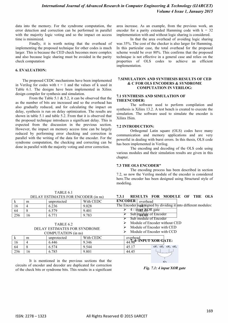
TABLE 6.1
DELAY ESTIMATES FOR ENCODER (in ns)
k m unprotected With CEDC overhead
16 4 6.236 9.028 44.7
64 8 6.579 9.401 42.89
256 16 6.771 9.783 44.48
TABLE 6.2
DELAY ESTIMATES FOR SYNDROME
COMPUTATION (in ns)
k m unprotected With CEDC overhead
16 4 6.446 9.346 44.98
64 8 6.574 9.544 45.17
256 16 6.785 9.801 44.45
It is mentioned in the previous sections that the
circuits of encoder and decoder are duplicated for correction
of the check bits or syndrome bits. This results in a significant
area increase. As an example, from the previous work, an
encoder for a parity extended Hamming code with k = 32
implementation with and without logic sharing is considered.
In that the area overhead of avoiding logic sharing
was 35%. The cost of the checker is also larger for Hamming.
In this particular case, the total overhead for the proposed
scheme would be over 80%. This confirms that the proposed
technique is not effective in a general case and relies on the
properties of OLS codes to achieve an efficient
implementation.
7.SIMULATION AND SYNTHESIS RESULTS OF CED
& C FOR OLS ENCODERS & SYNDROME
COMPUTATION IN VERILOG:
7.1 SYNTHESIS AND SIMULATION OF
THEENCODER: The software used to perform compilation and
synthesis is Xilinx 13.2. A test bench is created to execute the
simulation. The software used to simulate the encoder is
Xilinx ISim.
7.2 INTRODUCTION:
Orthogonal Latin square (OLS) codes have many
communication and memory applications and are very
powerful in dealing with burst errors. In this thesis, OLS code
has been implemented in Verilog.
The encoding and decoding of the OLS code using
various modules and their simulation results are given in this
chapter.
7.3 THE OLS ENCODER"
The encoding process has been described in section
7.2, so now the Verilog module of the encoder is considered
here.The encoder has been designed using Structural style of
modeling.
7.3.1 RESULTS FOR MODULE OF THE OLS
ENCODER The Encoder is designed by dividing it into different modules:
4 - input XOR gate
Sub module of Encoder
Sub module of Encoder
Module of Encoder without CED
Module of Encoder with CED
Module of Encoder with CCD
7. 4- INPUT XOR GATE:
Fig. 7.1: 4 input XOR gate
International Journal of Advanced Research in Computer Engineering & Technology (IJARCET)
Volume 4 Issue 1, January 2015
170 ISSN: 2278 – 1323 All Rights Reserved © 2015 IJARCET
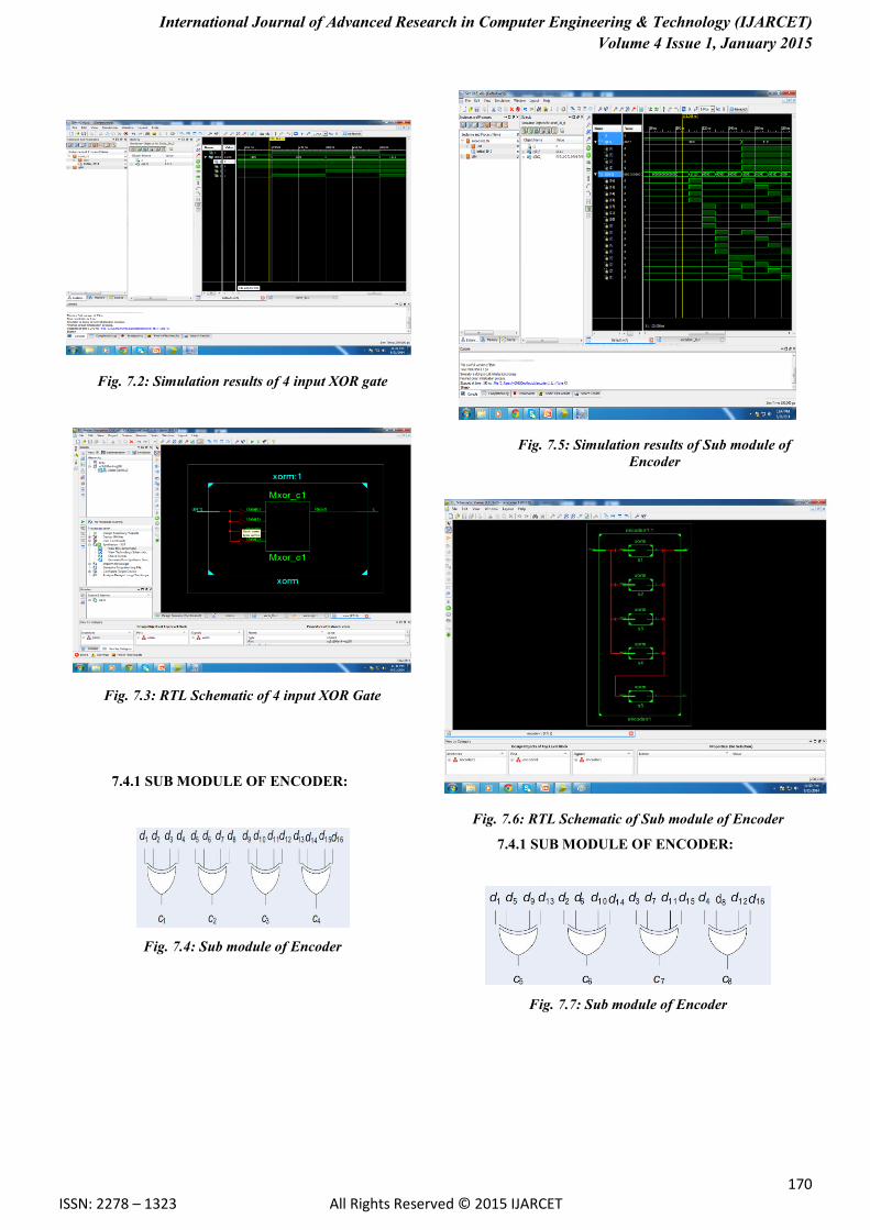
Fig. 7.2: Simulation results of 4 input XOR gate
Fig. 7.3: RTL Schematic of 4 input XOR Gate
7.4.1 SUB MODULE OF ENCODER:
Fig. 7.4: Sub module of Encoder
Fig. 7.5: Simulation results of Sub module of
Encoder
Fig. 7.6: RTL Schematic of Sub module of Encoder
7.4.1 SUB MODULE OF ENCODER:
Fig. 7.7: Sub module of Encoder

International Journal of Advanced Research in Computer Engineering & Technology (IJARCET)
Volume 4 Issue 1, January 2015
171 ISSN: 2278 – 1323 All Rights Reserved © 2015 IJARCET
Fig. 7.8: Simulation results of Sub module of
Encoder
Fig. 7.9: RTL Schematic of Sub module of Encoder
7.4.1 ENCODER WITHOUT CED:
Fig. 7.10: Encoder without CED
Fig. 7.11: Simulation results of Encoder without
CED
Fig. 7.12: RTL Schematic of Encoder without CED
7.4.1 ENCODER WITH CED:
International Journal of Advanced Research in Computer Engineering & Technology (IJARCET)
Volume 4 Issue 1, January 2015
172 ISSN: 2278 – 1323 All Rights Reserved © 2015 IJARCET
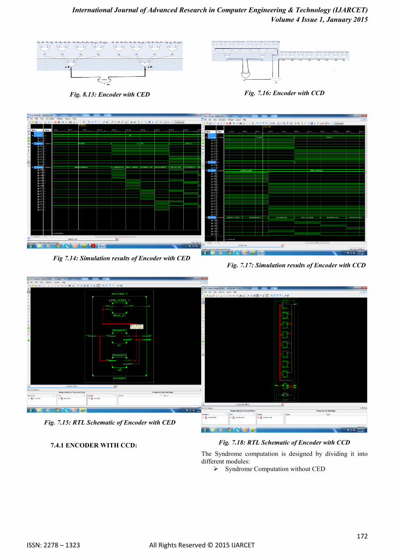
Fig. 8.13: Encoder with CED
Fig 7.14: Simulation results of Encoder with CED
Fig. 7.15: RTL Schematic of Encoder with CED
7.4.1 ENCODER WITH CCD:
Fig. 7.16: Encoder with CCD
Fig. 7.17: Simulation results of Encoder with CCD
Fig. 7.18: RTL Schematic of Encoder with CCD
The Syndrome computation is designed by dividing it into
different modules:
Syndrome Computation without CED

International Journal of Advanced Research in Computer Engineering & Technology (IJARCET)
Volume 4 Issue 1, January 2015
173 ISSN: 2278 – 1323 All Rights Reserved © 2015 IJARCET
Syndrome Computation with CED
Syndrome Computation with CCD
7.4.1 SYNDROME COMPUTATION WITHOUT
CED:
Fig. 7.19: Syndrome Computation without CED
Fig. 7.20: Simulation results of Syndrome
Computation without CED
Fig. 7.21: RTL Schematic of Syndrome Computation
without CED
7.4.1 SYNDROME COMPUTATION WITH CED:
Fig. 7.22: Syndrome Computation with CED
Fig. 7.23: Simulation results of Syndrome Computation with
CED
Fig. 7.24: RTL Schematic of Syndrome Computation with
CED
International Journal of Advanced Research in Computer Engineering & Technology (IJARCET)
Volume 4 Issue 1, January 2015
174 ISSN: 2278 – 1323 All Rights Reserved © 2015 IJARCET
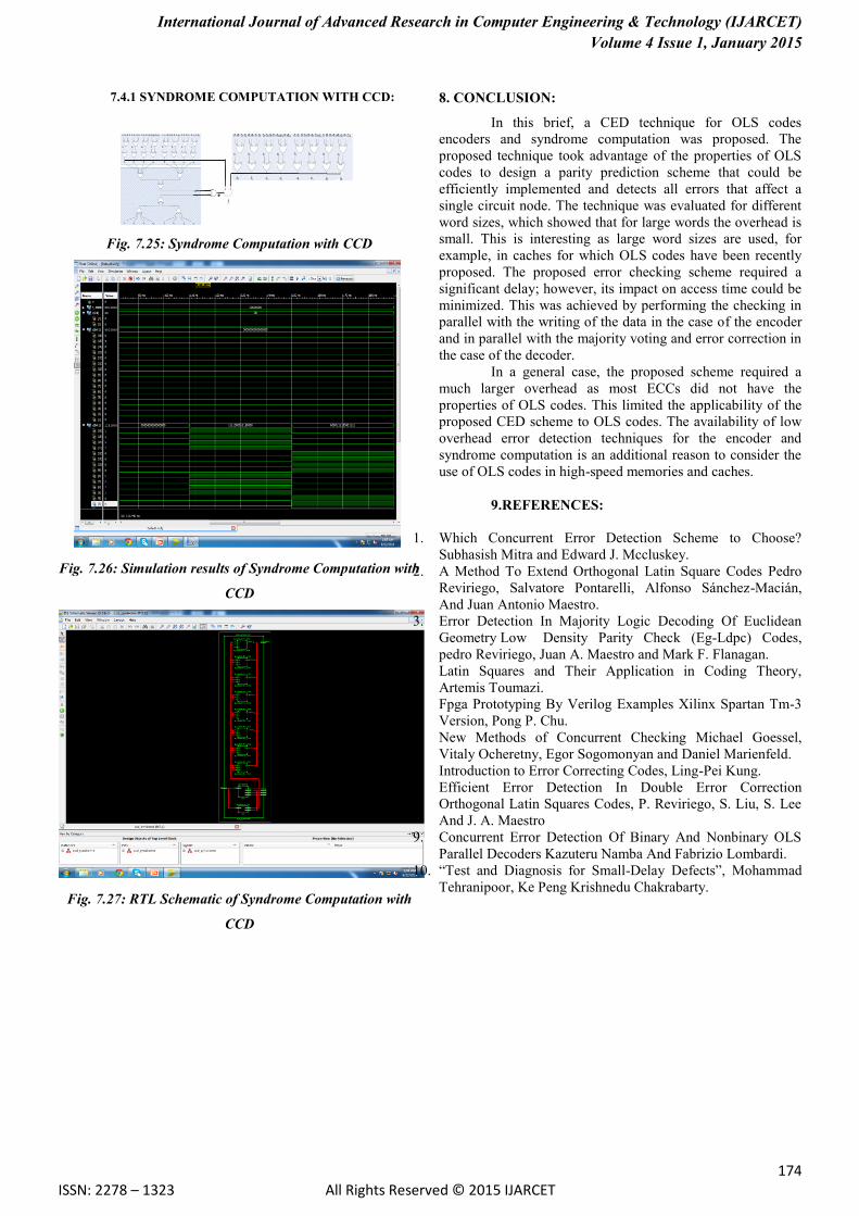
7.4.1 SYNDROME COMPUTATION WITH CCD:
Fig. 7.25: Syndrome Computation with CCD
Fig. 7.26: Simulation results of Syndrome Computation with
CCD
Fig. 7.27: RTL Schematic of Syndrome Computation with
CCD
8. CONCLUSION:
In this brief, a CED technique for OLS codes
encoders and syndrome computation was proposed. The
proposed technique took advantage of the properties of OLS
codes to design a parity prediction scheme that could be
efficiently implemented and detects all errors that affect a
single circuit node. The technique was evaluated for different
word sizes, which showed that for large words the overhead is
small. This is interesting as large word sizes are used, for
example, in caches for which OLS codes have been recently
proposed. The proposed error checking scheme required a
significant delay; however, its impact on access time could be
minimized. This was achieved by performing the checking in
parallel with the writing of the data in the case of the encoder
and in parallel with the majority voting and error correction in
the case of the decoder.
In a general case, the proposed scheme required a
much larger overhead as most ECCs did not have the
properties of OLS codes. This limited the applicability of the
proposed CED scheme to OLS codes. The availability of low
overhead error detection techniques for the encoder and
syndrome computation is an additional reason to consider the
use of OLS codes in high-speed memories and caches.
9.REFERENCES:
1. Which Concurrent Error Detection Scheme to Choose?
Subhasish Mitra and Edward J. Mccluskey.
2. A Method To Extend Orthogonal Latin Square Codes Pedro
Reviriego, Salvatore Pontarelli, Alfonso Sánchez-Macián,
And Juan Antonio Maestro.
3. Error Detection In Majority Logic Decoding Of Euclidean
Geometry Low Density Parity Check (Eg-Ldpc) Codes,
pedro Reviriego, Juan A. Maestro and Mark F. Flanagan.
4. Latin Squares and Their Application in Coding Theory,
Artemis Toumazi.
5. Fpga Prototyping By Verilog Examples Xilinx Spartan Tm-3
Version, Pong P. Chu.
6. New Methods of Concurrent Checking Michael Goessel,
Vitaly Ocheretny, Egor Sogomonyan and Daniel Marienfeld.
7. Introduction to Error Correcting Codes, Ling-Pei Kung.
8. Efficient Error Detection In Double Error Correction
Orthogonal Latin Squares Codes, P. Reviriego, S. Liu, S. Lee
And J. A. Maestro
9. Concurrent Error Detection Of Binary And Nonbinary OLS
Parallel Decoders Kazuteru Namba And Fabrizio Lombardi.
10. “Test and Diagnosis for Small-Delay Defects”, Mohammad
Tehranipoor, Ke Peng Krishnedu Chakrabarty.

International Journal of Advanced Research in Computer Engineering & Technology (IJARCET)
Volume 4 Issue 1, January 2015
175 ISSN: 2278 – 1323 All Rights Reserved © 2015 IJARCET
10. AUTHORS BIOGRAPHY:
S.SANTHOSH KUMAR is
from HYDERABAD, ANDHRAPRADESH. Studying
B.TECH 4th year ECE in VIDYA JYOTHI INSTITUTE OF
TECHNOLOGY from JNTUH. His areas of interests includes
VLSI,Wireless and Mobile communications,Digital signal pro
cessing,Image processing,Telecommunications,Embedded
systems, network security.