condenser - iiar org - international institute of ammonia ... august... · condenser | august 2011...
TRANSCRIPT

CondenserAugust 2011
PublishedbytheInternationalInstituteofAmmoniaRefrigerationasaservicetoitsmembersandtheIndustrialRefrigerationIndustry

ii Condenser | August 2011 | A Publication of the International Institute of Ammonia Refrigeration
MVP Multi-Valve PlatformMultiPle SolutionS to fit Your APPlicAtionMultiPle SolutionS to fit Your APPlicAtionAtionA
MVPMVPMVPMVPMVPMVPMVPMVPMVPMVPMVPMVPMVPMVPMVPMVPMVPMVPMVPMVPMVPMVPMVPMVPfor more information, call 866.4HAnSen or visit us online at www.hantech.com
Condenser | August 2011 | A Publication of the International Institute of Ammonia Refrigeration 1
200 k
0
400 k
600 k
800 k
JAN
WA
TER
USA
GE
(gal
lon
s)
MONTH
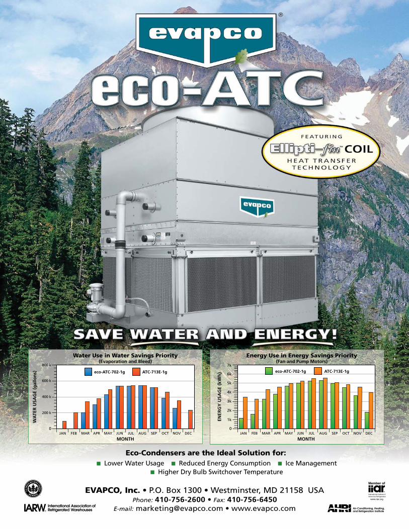
Water Use in Water Savings Priority(Evaporation and Bleed)
FEB MAR APR MAY JUN JUL AUG SEP OCT NOV DEC
eco-ATC-702-1g ATC-713E-1g
Energy Use in Energy Savings Priority(Fan and Pump Motors)
0
1k
2k
3k
4k
5k
6k
7k
JAN
ENER
GY
USA
GE
(kW
h)
MONTHFEB MAR APR MAY JUN JUL AUG SEP OCT NOV DEC
eco-ATC-702-1g ATC-713E-1g
EVAPCO, Inc. • P.O. Box 1300 • Westminster, MD 21158 USAPhone: 410-756-2600 • Fax: 410-756-6450
E-mail: [email protected] • www.evapco.com
Eco-Condensers are the Ideal Solution for:� Lower Water Usage � Reduced Energy Consumption � Ice Management
� Higher Dry Bulb Switchover Temperature
eco-ATC ad:Evapco 7/28/11 10:16 AM Page 1

International Institute of Ammonia Refrigeration
1001 North Fairfax Street, Suite 503
Alexandria, VA 22314 | www.iiar.org
Phone: 703-312-4200 | Fax: 703-312-0065
Condenser Staff
Publisher | Bruce Badger | [email protected]
Managing Editor | Bob Armstrong | [email protected]
Staff Writer | Andrea Fischer
Layout & Design | Laura Dugan
Illustrator | Ron Curameng
CONTENTS
3 Chairman’s Message
4 Application of Ammonia in U.S. Supermarkets
8 IIAR Code Advocacy Update
12 IIAR Government Affairs
16 First Encounters of the Wrong Kind, Part II
18 Ammonia Refrigeration Foundation Update
24 Choosing the Right Ammonia Sensor Technology
32 Synergy Savings
34 Operation Strategies for Load Management and Reduction in Cold Storage Facilities
36 From the Technical Director
2 Condenser | August 2011 | A Publication of the International Institute of Ammonia Refrigeration
Developed for the industry by the industry
n A comprehensive safety management tool
n A streamlined regulatory documentation solution
n A guide for facilities with less than 10,000 pounds
of ammonia
As the leading authority on ammonia refrigeration,
the International Institute of Ammonia Refrigeration
developed the Ammonia Refrigeration Management
(ARM) Program to help small facilities improve safety,
enhance system reliability and assist with regulatory
compliance. ARM is intended to assist facilities with a
charge of less than 10,000 lbs. of ammonia that are
subject to inspection under the General Duty Clause.
ARM is a comprehensive safety management tool. It
draws from the best ideas contained in Process Safety
Management and Risk Management, simplifies the
application of these concepts and streamlines the
documentation process.
www.iiar.org Order your copy of the ARM Program today!

Condenser | August 2011 | A Publication of the International Institute of Ammonia Refrigeration 3
At its June, 2011 meeting, the Board of Directors voted to approve the expansion of an existing membership category to provide a limited level of membership benefits at a reduced rate under the IIAR Affiliate category. Only individuals living and working in Article 5 and BRIC countries (Brazil, Russia, India, and China) will be eligible for this status. No company name will be associated with the membership. Those companies located in Article 5 and BRIC countries wishing to promote their corporate identity through their membership in IIAR must join as regular members.
Organized efforts to recruit new IIAR Affiliate members are already underway in Latin America with the appointment of Federico Alarcón López as the IIAR official representative in that part of the world. Federico will assist the groups of volunteers from the International Committee that are leading the organization of regional IIAR meetings in Latin America. He will also promote membership in IIAR.
Later this fall, IIAR representatives will travel to China and India. An important part of that mission will be to build on the relationships that have been evolving over the past few years and establish partnerships that will support the expansion of the IIAR mission in those two countries.
I want to stress that these efforts to reach out into developing regions of the world will not diminish the level of service provided to our traditional membership base which remains extremely important to the strength of IIAR. These efforts are an effort to live up to a vision that was identified 40 years ago: “To be recognized as the world’s leading advocate for the safe, reliable and efficient use of ammonia and other natural refrigerants for industrial applications.”
Chairman’s Message
by Adolfo Blasquez
More than forty years ago, a group of industry
professionals in the United States conceived of an organization that would promote advocacy, safety and education in the ammonia refrigeration industry. This small group of individuals — representing themselves and several businesses, including engineers, contractors, manufacturers and end users — rallied around an effort to fight a code change in the United States that would have had a negative impact on the industry. In the end, they were successful in their effort. But the group saw a potential for much more than that. They had a vision that the organization could grow to have an influence around the world. They had the foresight to call the organization the International Institute of Ammonia Refrigeration (IIAR). Slowly, but surely, the realization of that vision has evolved.
In the early days, word of the new organization spread throughout North America and into Europe; then eventually elsewhere around the world to South America, Australia, Asia and Africa. The growing interest was fueled by the movement to use natural, environmentally friendly refrigerants, like ammonia and CO2, rather than synthetic refrigerants that contribute to ozone depletion and global warming.
Over the years, several individuals from Sweden, Switzerland, Germany, the United Kingdom, Japan, Mexico, Canada and Brazil have contributed to the growth of IIAR by serving on the IIAR Board of Directors. They, along with many Americans, have lent their voices to promote IIAR to the four corners of the world. They have traveled to developing countries like Russia, China, Saudi Arabia, Macedonia, South Africa, Brazil and many other Latin American countries to deliver first-hand, the message that IIAR is recognized as an effective advocate for the use of natural refrigerants in industrial refrigeration applications and is the most comprehensive source of technical information on the topic.
As IIAR’s reputation has grown around the world, interest in the annual IIAR Industrial Refrigeration Conference & Exhibition and in membership in our organization has also grown. To address the growing demand, the IIAR Board of Directors has launched a new effort to meet the needs of potential members in Article 5 (developing) countries and the BRIC countries (Brazil, Russia, India and China).
InMemoriamBillKahlert, an Honorary Life Member of
IIAR, former IIAR President and major Ammonia Refrigeration Foundation (ARF) contributor, died August 8, 2011 after a long battle with cancer. Kahlert, 85, served as President of IIAR in 1988– 89. He was named ARF Philanthropist of the Year in 2009 and the Bill Kahlert Foundation has been a generous contributor to the ARF Trust Fund.
Kahlert spent his career in industrial refrigeration. He was co-founder of EVAPCO, and while he officially retired several years ago, he has remained involved with the company.

4 Condenser | August 2011 | A Publication of the International Institute of Ammonia Refrigeration
by Caleb Nelson, PE, LEED AP, CTA Architects Engineers
Introduction
In the U.S. supermarket industry, the fear of ammonia (R717) and the misconceptions of the codes that govern it, coupled with a lack of knowledge pertaining to the systems,
serve as major hurdles that will need to be cleared before ammonia can be accepted as a viable alternative to traditional halocarbon refrigerants. The goals of this article are to: 1) expose ammonia’s potential for safe application; 2) look into the codes governing the majority of the U.S. and determine what restrictions may apply; 3) introduce what types of systems have successfully been utilized elsewhere in the world in supermarket applications; and 4) provide some basic design considerations regarding the selection and operation of the basic components of these types of ammonia systems.
SafetyThrough the many years that ammonia has been utilized as a
refrigerant, engineers have been able to develop R717 systems to a point where they can operate at high levels of efficiency and as safely as any other type of refrigeration system—provided they are installed and operated in accordance with the safety codes. Conceptions of ammonia as an unsafe refrigerant are, to some degree, justifiable due to the fact that it is toxic and classed as slightly flammable. It is the belief of the author, however, that due to the type and application of the system that will be described here, any risk due to ammonia’s toxicity and flammability can be nearly eliminated.
The majority of ammonia’s use as a refrigerant today is in large, industrial systems, which may contain as much as 200,000 lbs. of ammonia or more. In most industrial systems, ammonia plants are located within the building and ammonia is carried in distribution piping to areas where employees work. The combination of this type of application and large ammonia charges creates a
Ammonia in U.S. Supermarkets continued on page 6
Application ofAmmonia
Supermarketsin U.S.

Condenser | August 2011 | A Publication of the International Institute of Ammonia Refrigeration 5
Scan with yoursmartphone for more information.
Emerson’s innovative heat pump technology, featuring Vilter single-screw compressors, saves money and the environment.
A key ingredient in Nestle’s energy efficient chocolate factory is an ammonia heat pump system that converts wasted heat into usable energy. Made possible by Emerson’s technology and Vilter single screw compressors, this solution delivers hot water for process heating far more efficiently than traditional methods such as gas or coal-fired boilers. Learn more about how Nestle partnered with Emerson and Star Refrigeration to reduce their total energy costs as well as their carbon footprint.Visit EmersonClimate.com/IndustrialHeatPumps
The Emerson logo is a trademark and a service mark of Emerson Electric Co. ©2011 Emerson Electric Company
RIGHT NOWNestlé® is crunching energy costs in its chocolate factory by up to 50 percent.

6 Condenser | August 2011 | A Publication of the International Institute of Ammonia Refrigeration
scenario where the potential for accidents and unsafe practice can sometimes be substantial. In recent years, industrial systems have utilized secondary fluids to minimize potential accidents involving employees within the building by restricting the ammonia charge to the machinery rooms; however, there still exists the possibility of releasing these large charges to the atmosphere.
Since the subject of this paper is the application of ammonia in supermarkets, it is extremely important to differentiate between the industrial application of ammonia and the commercial, supermarket application of ammonia. Less than 200 or 300 pounds of ammonia can typically be expected for a supermarket application. Also, due to codes that will be discussed later, an ammonia system cannot be installed within a commercial space. Therefore, an outdoor, rooftop, ammonia chiller is the most feasible option. A packaged type of system with the refrigerant charge residing outdoors alleviates the potential for accidents involving employees and customers within the building. These two key differences suggest that a supermarket ammonia system would be inherently safer than most industrial systems; however, it would be foolish to rely on these qualities alone to assure a safe utilization of ammonia in supermarkets.
Both the Environmental Protection Agency (EPA) and the Occupational Safety and Health Administration (OSHA) have safety programs that are required for systems with more than 10,000 lbs of ammonia. Although these regulations are not required for supermarket-size systems, there are still many system design considerations that should be made to ensure safe applications of ammonia for supermarkets. Just as with any refrigeration system, a risk assessment should be performed to determine the appropriate safeguards and measures to reduce the risk to an acceptable level.
Performing an atmospheric dispersion model of an ammonia release is something that is common for industrial systems, and can be done for small commercial systems as well. It would be handy if a single analysis could be performed to cover all “worst case” conditions; unfortunately, weather patterns, humidity levels, and the off-site receptors change with each new location. Therefore, the off-site consequences for a “worst case” ammonia release is something that should be explored for each location until experience exposes the safety of small rooftop systems.
Depending on the site location, we can predict the behavior of an ammonia release based upon a scenario such as a pressure release valve (PRV) lifting. When released, the pressure in the system drops and allows the PRV to close which allows for an intermittent release. The natural rise and dissipation of ammonia gas (due to ammonia gas being lighter than air) teamed with an intermittent release and a small charge generates a scenario where a release through a PRV will most likely go unnoticed in most locations. Other scenarios do exist that may interfere with the rise and dissipation of ammonia such as down drafts from surrounding buildings or
extreme humidity levels. As previously mentioned, the “worst case” needs to be considered separately for each location.
Using an outdoor ammonia chiller enclosed in removable housing (instead of applying an outdoor chiller “house”) eliminates the possibility for technicians to ever be trapped in a toxic environment due to a leak while still providing protection for the chiller from the outdoor elements. Regardless, leak detection should be used in coordination with an exhaust system to prevent ammonia concentrations at the chiller from ever reaching flammable levels. Since ammonia gas rises, an exhaust fan at the top of the unit or in a chimney—exhausting upward—would further promote the rise and dissipation of ammonia into the air.
Beyond these design considerations, a preventative maintenance program is necessary for all ammonia systems to assure that all equipment and safety systems are functioning properly. Periodic testing of components such as the leak detection system, alarms, evacuation system, and safety cut out switches should be performed and pressure relief valves should be replaced every five years. Inspection checklists should also be developed to aid in the swift discovery of any physical damage or corrosion to the system. Finally, training and education on the systems and the safe work practices for ammonia is critical to ensure that technicians can safely and effectively carry out these tasks.
CodesThrough researching the international codes (IBC 2006, IMC
2006 chapter 11 & IFC 2006 section 606) and others that apply (ANSI/IIAR 2-2008 & ANSI/ASHRAE Standards 15-2007 & 34-2007), no major deterring restrictions have been found for the use of an ammonia system in a supermarket. This does not disregard that certain counties and states within the U.S. have adopted their own local requirements for an ammonia system—regardless of the system size. New Jersey, Chicago, and Los Angeles are examples. Possibly the best approach would be to avoid these areas (to begin with) when considering locations to implement ammonia commercially. Doing so could allow the commercial ammonia market to grow and become familiar prior to the day that the U.S. is possibly faced with a phase out of HFCs—at which time, the pressure for authorities to be more open-minded toward the use of natural and efficient refrigerants will be much greater.
Before discussing further the code restrictions, it is important to acknowledge the EPA’s Significant New Alternatives Policy (SNAP) program. This program has been set up under the Clean Air Act and is designed to identify and regulate approved alternatives to replace ozone-depleting chemicals. It is illegal to utilize a refrigerant that has not been approved by the SNAP program. Before the first CO2 system could be installed in the US in recent years, CO2 had to traverse a year-and-a-half-long application process to become approved for use. The main focus of this process is to ensure that the chemical is safe for people and the environment. It is
Ammonia in U.S. Supermarkets continued from page 4

Condenser | August 2011 | A Publication of the International Institute of Ammonia Refrigeration 7
in table 1103.1—is for the system to be located outdoors or in a machinery room. Furthermore, section 1104.3.3 actually excludes ammonia from the 1,100 pound (total for all occupancies) restriction that other B2 refrigerants must adhere to.
Finally, it should also be noted that all ammonia systems, regardless of the application, should adhere to all the requirements and specifications provided by the IIAR and by ASHRAE 15. ASHRAE 15 provides similar requirements to those found in the International Mechanical Code, and ANSI/IIAR 2-2008 covers everything the equipment manufacturers will need to observe (emergency pressure control systems, system component specs, acceptable grades of steel for flanges and fittings, etc).
SystemsOne specific example of an ammonia, supermarket system
that has been operating since mid November of 2009 can be seen in a Pick ‘n Pay store in Strand, South Africa. This store uses one rack that contains three ammonia compressors and three CO2 compressors. Each ammonia compressor is an open-drive, reciprocating compressor equipped with cylinder unloading. The ammonia evaporator is a plate and shell type which is connected to a low pressure surge vessel. One side of the evaporator condenses the CO2 low-temp system and the other side cools the glycol for the secondary, medium-temp system. This entire system is located in a rooftop, machinery room equipped with leak detection and an automatic exhaust system. Adjacent to the machinery room is the ammonia evaporative condenser which uses a high pressure float system to expand the liquid and regulate the flow directly to the evaporator. Because of the float system there was no liquid receiver needed which allowed for a small ammonia charge of approximately 286 lbs. to be achieved.
Another system that is a good candidate for a supermarket application is the Low Pressure Receiver (LPR) system. The evaporator in this type of system remains fully wetted and actually realizes a slight overfeed driven by pressure differences within the system. Figure 1 is a basic schematic of a low charge LPR system cascaded with a CO2 system:
Figure1(LowPressureReceiverSystem)
AsapparentinFigure1,thereisnohighpressurereceiverneeded;however,theLPRmustbe
sizedlargeenoughtocontainthemajorityoftheammoniachargetoallowformaintenance.
ThecompressorwillmaintainthesaturatedsuctionpressureintheLPRbypumpingdry
ammoniagastothecondenser.Liquiddrainingfromthecondenseristhensub‐cooledthrough
aheatexchangerlocatedatthebottomoftheLPRandthenisfedtotheevaporator.Amild
expansionistypicallyprovidedbyamotorizedvalveattheevaporatorinletwhichiscontrolled
byacondenserdrainfloat.Thereturnlinefromtheevaporatorisa“wetreturn”(liquid/suction
mix)whichfeedsintotheLPRwherethesuctionandgasarethenseparated.
TheLPRsystemhasbeenintroducedinthispaperbecauseitcandeliverthesame
efficiencyandperformanceasotherammoniasystemswhilecontainingaverysmallammonia
charge.Figure1depictsplate‐typeheatexchangersforboththeevaporatorandcondenser
whichallowsforthelowestchargepossible.Typicallychargesof0.8poundspertonof
refrigerationhavebeenacceptedforthesesystems,whenhistorically,systemswithshelland
tubeevaporatorsandhighpressurereceivershaveneededasmuchas12poundspertonof
refrigeration.1Sincethesenumbershavebeenderivedfromindustrialapplications,itwould
beunrealistictoexpectthesameratiosforsmallersystemsinsupermarkets.Conservatively,if
weassume1.5poundspertonofrefrigerationandconsiderastandard,55,000square‐foot
supermarketwitha1.5millionBTUload(125tons),we’releftwith188poundsofammoniafor
theentirestore.
Beyondthelowchargesthatbothofthesetypesofsystemsareabletoachieve,the
fundamentalmeansforwhichhighlevelsofefficiencycanbereachedincomparisonto
standardsupermarketsystemsarelistedbelow:
Figure 1 (Low Pressure Receiver System)
comforting to know that ammonia has in fact been deemed safe, and has already been approved by the EPA’s SNAP program for use in secondary applications in supermarkets.
Until recently, ASHRAE 34 classified R717 as a B2 refrigerant, which means it was designated as toxic and flammable. As the result of a recent addendum, R717 is now classed as a B2L refrigerant along with other mildly flammable refrigerants that have a proven burning velocity less than or equal to ten cm/s. Ammonia’s toxicity class remains unchanged but it is now recognized to be less flammable than a B2 refrigerant. This classification shift is still very new and has yet to materialize into any tangible changes in the codes pertaining to ammonia’s use. Therefore we must still treat ammonia like a B2 refrigerant.
This B2 classification is the foundation for which all codes and restrictions are applied to ammonia, the most influential of which, restricts ammonia from being used in any “occupied space”. Therefore, an indirect, secondary system represents the only choice in order to comply—an example being, an ammonia chiller located on a rooftop. This type of system could both chill a secondary fluid, such as a propylene glycol-water mixture or CO2, and pump it into the store to refrigerate the product. In such a system, the ammonia is fully limited to the outdoors; and as an added bonus, the ammonia charge is dramatically reduced.
Depending on the state or county, one may need to incorporate a system to dilute, diffuse, or burn ammonia in the event of a discharge. However, none of these discharging methods are necessary if the fire code official determines upon review of a technical opinion report—submitted by a professional engineer—that a fire, health, or environmental hazard would not result from discharging ammonia directly to the atmosphere. It should be noted that the preferred method of release by ASHRAE and the International Institute of Ammonia Refrigeration (IIAR) is a direct release to the atmosphere and that only in special applications may it be determined necessary to utilize a burning, diffusing, or diluting system.
Per the International Code, a supermarket is classified as a “mixed occupancy” since the sales floor classifies as a “commercial occupancy” and the receiving area and utility rooms classify as “industrial occupancies.” In fact, if an ammonia system was limited to the industrial portion of the building, it would fall under the same restrictions as any other Industrial ammonia application. However, there are additional freedoms realized by limiting the ammonia to the outdoors. For example, the International Mechanical Code (IMC) allows us to classify our system as “Low Probability” if the system components are “isolated” from the building. Or per ASHRAE 15, an outdoor unit is considered low probability if there is no way the refrigerant can enter an occupied space. With an outdoor, low probability system, the ammonia restriction found on table 1103.1 in the IMC (2006) of 0.022 pounds per 1,000 cubic feet does not apply. Section 1104.2 supports this by stating that the only way to exceed the refrigerant amounts shown
Ammonia in U.S. Supermarkets continued on page 20

8 Condenser | August 2011 | A Publication of the International Institute of Ammonia Refrigeration
By Jeffrey M. Shapiro, PE., FSFPE
Codes,StandardsandMachineryRooms
Anyone in the industrial refrigeration business should be familiar with the term “machinery room,” but ask ten people to tell you when a machinery room is required or
what safety features machinery rooms must contain, and you’re likely to get ten (or more) different answers. The lack of a singular answer is easily explained. First, in the United States, there are several codes and standards that govern when machinery rooms are required. Second, the regulations in these documents are not entirely consistent with one another, and third, the regulations often change from one edition of a code or standard to the next. Want a better handle on the topic? Read on.
The predominant U.S. codes that regulate machinery rooms are the International mechanical, fire and building codes; the Uniform Mechanical Code (UMC); and the NFPA 1 Uniform Fire Code. These documents are significantly supplemented by two standards, ASHRAE 15 Safety Standard for Refrigeration Systems and for Ammonia Systems IIAR-2 Equipment, Design, and Installation of Closed-Circuit Ammonia Mechanical Refrigerating Systems.
Section numbers quoted in this article reference the 2009 editions of the International and Uniform Codes, the 2010 edition of ASHRAE 15, and the 2008 edition of IIAR-2 with Addendum A (2010), and it should be noted that this article addresses new construction and construction of equipment and facilities that were governed by similar regulations to those discussed herein at the time of construction. In general, construction related requirements in building, fire and mechanical codes, ASHRAE 15 and IIAR-2 are not retroactive to existing occupancies.
It’s important to remember that, when dealing with a topic that is regulated by both a code and standard, the code trumps the standard whenever a conflict occurs. At the state and local level in the U.S., codes are typically the primary enforcement documents adopted by jurisdictions. Standards are then adopted by one or more references within a code. To make the hierarchy clear, all model codes include a general statement establishing that referenced standards are subordinate, and in the case of refrigeration systems, the guidance is even more specific. The International Mechanical Code (IMC) and UMC include the following statements in Chapter 11:
IMC 1101.6 Refrigeration systems shall comply with the requirements of this code and, except as modified by this code, ASHRAE 15. Ammonia-refrigerating systems shall comply with this code and, except as modified by this code, ASHRAE 15 and IIAR 2.
UMC 1102.0 Except as modified by this code, refrigeration systems shall comply with ASHRAE 15. In addition, ammonia refrigeration systems shall comply with IIAR 2.
In the past decade, the need for conflict resolution among codes and standards has been lessened as a result of IIAR’s efforts to achieve uniformity among these documents. Although, differences remain, machinery room regulations are fairly consistent in state and local regulatory documents.
At the Federal level, OSHA and EPA also have authority over some facilities with refrigeration equipment, but state and local codes will typically dictate whether a machinery room is required and what safety features are provided therein. This is so because state and local governments are the primary regulators of building design and construction, and the need for a machinery room is a design decision.
WhenandWhyMachineryRoomsareRequiredThe purpose of providing a machinery room is to isolate
major equipment handling refrigerant from occupied portions of buildings. The goal is to minimize adverse consequences of a refrigeration leak to building occupants.
As a general rule, codes and standards seek to limit the risk of leaked refrigerants achieving hazard thresholds, called refrigerant concentration limits (RCL), in occupied areas. RCLs are based on hazard classifications assigned by ASHRAE 34, Designation and Safety Classification of Refrigerants, and they consider various health effects, such as asphyxiation, cardiac sensitization and toxicity, and/or flammability. They also include a factor of safety to provide a buffer between a worst case release concentration and danger thresholds.
RCL calculations assume a worst case release of refrigerant dispersed uniformly into the building volume served by a refrigeration system or circuit. If that calculated average refrigerant concentration exceeds the RCL for the refrigerant involved, codes and standards will usually require the refrigerant handling equipment to be located outside of normally occupied areas, either in a machinery room or outdoors. ASHRAE 15 and the IMC make the option to put equipment outdoors clear (See ASHRAE 15 Section 7.4 and IMC Section1104.2). The UMC does not.
UMC Section 1107, applied literally, requires refrigeration equipment to be placed in a machinery room when various
IIAR Code Advocacy Update
Code Update continued on page 10

Condenser | August 2011 | A Publication of the International Institute of Ammonia Refrigeration 9

10 Condenser | August 2011 | A Publication of the International Institute of Ammonia Refrigeration
IBC (Sections 1015.4 and 1015.5)• The process and storage areas must have at least two
exits or exit access doors if the floor area exceeds 1,000 square feet.
• The travel distance from anywhere in a process or storage room without fire sprinklers to an exit or exit access door is limited to 150 feet.
IMC and ASHRAE15 (IMC Section 1104.2.2 and ASHRAE 15 Section 7.2.2)
• The process and storage areas must be separated from the remainder of the building by tight construction with tight-fitting doors.
• Access to process and storage areas must be restricted to authorized personnel.
• A minimum floor area per occupant density limit (occupant load) may apply to process and storage areas that are below grade level.
• Refrigerant leak detection must be provided in the process and storage areas.
UMC (Section 1105.3)• The process and storage areas must be separated from
the remainder of the building by tight construction with tight-fitting doors.
• Refrigerant leak detection must be provided in the process and storage areas.
GeneralVersusSpecialMachineryRoomsFor cases where refrigeration machinery rooms are
required, ASHRAE 15 (Sections 8.11 and 8.12) and the IMC (Sections1105 and 1106) formally establish two classes of machinery rooms, “general” and “special.” All machinery rooms must meet the general requirements, and machinery rooms containing flammable refrigerants must usually meet the special requirements as well (very small quantities of flammable refrigerants in a machinery room provided primarily for non-flammable refrigerants may be exempted). The general requirements for machinery rooms include refrigerant leak detection, room ventilation and various other basic safety features. The special requirements for machinery rooms that have flammable refrigerants are oriented towards fire safety, such as ignition source control and fire protection features.
The UMC is similar in application to ASHRAE 15 and the IMC, but the UMC’s machinery room requirements are distributed among numerous feature-oriented sections rather than being accumulated into sections that comprehensively address machinery rooms.
When designing a machinery room, one must also remember to comply with IIAR-2, which contains many new and updated requirements in Section 13 of the 2010 Addendum A. Nevertheless, when conflicts occur between
thresholds are exceeded. No allowance is provided to place vessels, pumps and various other system components outside for most systems containing refrigerants that have health or flammability hazards. Nevertheless, the UMC does not specifically require that a refrigeration machinery room must be enclosed, so technically, an outdoor area that satisfies the safety objectives set forth for machinery rooms can be considered as meeting the code. Such an interpretation is reasonable when one considers that ASHRAE 15 and the IMC specifically allow any refrigeration equipment to be located outdoors and that fire codes permit process and storage equipment for any hazardous material, many of which are far more hazardous than refrigerants, to be located outdoors as well.
TheIndustrialOccupancyExceptionA key exception to the RCL based machinery room rule is
industrial occupancies. An industrial occupancy is defined by ASHRAE 15 as “a premise or that portion of a premise that is not open to the public, where access by authorized persons is controlled, and that is used to manufacture, process, or store goods such as chemicals, food, ice, meat, or petroleum.” The IMC uses similar terminology, but the UMC uses the term “refrigerated process and storage areas,” which is functionally equivalent. For purposes of this discussion, the term “industrial occupancies” will be inclusive of UMC refrigerated process and storage areas, and vice versa.
In industrial occupancies, codes and standards allow some major refrigerant-handling equipment, which would otherwise be required to be in a machinery room, to be located in occupied spaces. Such equipment includes:
IMC and ASHRAE 15: Refrigerant-containing parts in systems not exceeding 100 horsepower; evaporators used for refrigeration or dehumidification; condensers used for heating; control and pressure relief valves for such evaporators and condensers; and connecting piping [IMC Section 1104.2.2 (7) and ASHRAE 15 Section 7.2.2 (7)].
UMC: Evaporators and piping within rooms or spaces used exclusively for processing or storage of materials under refrigerated conditions (UMC Section 1105.3), and condensers (UMC Section 1106.7).
These exceptions acknowledge and allow for certain design benefits associated with the use of direct expansion evaporators for industrial cooling and direct condensers for industrial heating. However, the exceptions come with strings attached.
In the case of ammonia refrigeration systems, refrigerated process and storage areas containing ammonia evaporators must comply with the following conditions. Note that the International Building Code (IBC) requirements are additive to applicable mechanical code/standard requirements.
Code Update continued from page 8
Code Update continued on page 15

Condenser | August 2011 | A Publication of the International Institute of Ammonia Refrigeration 11
IIAR2012INDUSTRIALREFRIGERATIONCONFERENCE&EXHIBITION
milwaukeewisconsinmarch18–21
78780_IIAR_2012ad.indd 3 8/3/11 1:32 PM
FREE! IIAR Ammonia Safety Training DayMarch 18, 2012 in Milwaukee
Details coming soon

12 Condenser | August 2011 | A Publication of the International Institute of Ammonia Refrigeration
under the Homeland Security Act (HSA). By placing the authorities under the HSA, primary jurisdiction of CFATS would lay with the Homeland Security Committee and somewhat lessen the Energy and Commerce Committee’s power related to CFATS policies.
Key amendments adopted during the committee mark-up included:
• Imposing a deadline on DHS to notify a facility of approval or disapproval of a security vulnerability assessment or site security plan 180 days after DHS receives it. If an assessment or plan is disapproved, within 14 days the Secretary must provide written notification that includes an explanation for the disapproval. (offered by Rep. Sanchez – CA)
• Allowing individuals holding a TWIC card, or other alternative security background check as determined by the Secretary to access to high-risk chemical facilities. (offered by Rep. Jackson Lee – TX)
• Requiring DHS to provide technical assistance for owners and operators of chemical facilities (that meet the Small Business Administration’s definition of “small business”) who request it as part of their preparation for the security vulnerability assessment or site security plan.
Ranking Member of the committee, Benny Thompson (MS) offered a substitute amendment similar to CFATS legislation passed by the committee when he was chairman last year. His amendment would have established IST requirements and included other provisions of concern to industry. His amendment failed largely along party lines, further demonstrating the impact of the 2010 mid-term elections on issues such as chemical facility security.
With two bills having been approved by different committees of jurisdiction, the next step will be bringing legislation to the floor for consideration by the full House of Representatives. House leadership is currently weighing its options between the two bills and debating whether to craft a bill combining provisions from both, or simply advancing one of the committee passed versions. With a limited number of legislative days remaining before the end of September, it is expected that a decision on how to proceed will be made sometime this summer.
Meanwhile, the Senate Committee on Homeland Security and Government Affairs has been at work on its
by Lowell Randell, IIAR Government Affairs Director
HouseandSenateCommitteesAdvanceCFATSReauthorization
The Chemical Facilities Anti-Terrorism Standards (CFATS) Program is currently operating under authority which will expire at the end of September 2011. As has been previous
reported in The Condenser, Congress has struggled over the last two years to provide a long term reauthorization of the CFATS program due to disagreements over policies such as inherently safer technology (IST). This string of short term extensions has led to uncertainty over the long term future of the program and potential changes that companies would need to consider to remain in compliance. While the number of legislative days before the current authority expires continues to dwindle, recent committee activity in both the House and Senate suggests that a longer term reauthorization may be possible this year.
On the House side, the two committees of jurisdiction, the House Homeland Security Committee and the House Energy and Commerce Committee have each considered and passed their own versions of CFATS reauthorization. On May 26th, the House Energy and Commerce Committee approved H.R. 908, the Full Implementation of the Chemical Facility Anti-Terrorism Standards Act. The bill garnered some bipartisan support, as five Democrats joined 28 Republicans for a vote of 33-16.
As originally introduced, the bill would have extended authority for the program until October 2017. However, during committee consideration, an amendment by Representative Shimkus of Illinois was accepted that would authorize the program until October 2018. Shimkus was the author of the only other amendment to be approved, which provides that no additional background checks are necessary for holders of valid transportation security cards (such as “TWIC cards”), or equivalent alternative security cards. Despite efforts by some committee members, H.R. 908 does not include any provisions related to inherently safer technology.
The House Homeland Security Committee also recently took action on CFATS reauthorization. On June 22, the committee met to mark-up H.R. 901, the Chemical Facility Anti-Terrorism Security Authorization Act of 2011. After considering a number of amendments, the committee approved the bill by a bipartisan tally of 26 – 5, with eight Democrats voting for adoption.
Similar to the bill passed by the Energy and Commerce Committee, H.R. 901 would also extend the CFATS program through September 2018, but also includes a codification of some of the current programs regulations and places them Government Affairs continued on page 14
IIAR Government Affairs

Condenser | August 2011 | A Publication of the International Institute of Ammonia Refrigeration 13www.danfoss.us/icfDanfoss • Refrigeration & Air Conditioning Division • 11655 Crossroads Circle • MD 21220 • Baltimore • MD • Phone: (410) 931-8250 • E-mail: [email protected]
> 9300working days saved
The 15,000 ICF Valve Stations installed and running right now have provided our customers a total time saving of more than 9300 working days.
Save Valuable Time with the Unique ICF Control Solution
Save Valuable Timewith the ICF Valve StationReal value comes from time and cost savings. The unique ICF modular system allows you to install just one valve station with only two welds. Combine this with significant time-savings during engineering and service to experience the ultimate in efficiency and cost savings. The high pressure rating of 754 psig makes the ICF suitable for CO2 and future high pressure refrigerants.
MAKING MODERN LIVING POSSIBLE

14 Condenser | August 2011 | A Publication of the International Institute of Ammonia Refrigeration
to aid in the implementation of CFATs and the voluntary technical assistance program.
While Congress debates the future of CFATS, the Department of Homeland Security continues to implement the program. As a part of the department’s activities, they have recently invited public comment regarding its proposal to collect information under what they are calling the CFATS Personnel Surety Program (PSP). The PSP is being developed as a part of the CFATS risk-based performance standard related to personnel sureties that require facilities to perform appropriate background checks on and ensure appropriate credentials for facility personnel, and as appropriate, for unescorted visitors with access to restricted areas or critical assets. DHS is proposing that the PSP be the mechanism by which facilities must meet these requirements. Facilities would be required to submit to DHS personally-identifying information regarding individuals seeking access to restricted areas and critical assets at the facility. DHS would then arrange for these individuals to be checked against the FBI’s classified Terrorist Screening Database (TSDB).
IIAR, along with a number of like-minded industry organizations have concerns with the Department’s PSP proposal. There is a feeling that the PSP program, as proposed
own version of CFATS reauthorization. On June 29th the committee met to consider S. 473, the Continuing Chemical Facilities Antiterrorism Security Act. The bill was approved with bipartisan support by a vote of 8 to 2. Like its House counterparts, S. 473 would extend authority for the current CFATS program. However, the Senate bill only provides authority through October 2015.
S. 473 also includes a number of other provisions not included in either House bill, such as:
• the development of voluntary exercise and training programs to improve collaboration with the private sector and State and local communities under the CFATS program;
• the creation of a voluntary technical assistance program under the existing CFATS structure that would allow DHS, at the request of the owners/operators of covered chemical facilities, to provide recommendations or assistance to covered facilities to aid in compliance with the CFATS program or to reduce the risk of consequences of a terrorist attack on the covered facility; and,
• the creation of a chemical facility best practices clearinghouse and private sector advisory board at DHS
Government Affairs continued from page 12
In July 2009, the Occupational Safety and Health Administration (OSHA) established a National Emphasis Program (NEP) for chemical facilities. The program
began as a pilot in Region 1 (New England), Region 7 (Midwest) and Region 10 (Pacific Northwest), with state plan states having the option to adopt the NEP pilot. The stated purpose of the chemical facility NEP was to reduce or eliminate workplace hazards associated with the release of highly hazardous chemicals (HHCs). According to OSHA, as of June 30, 2011, 207 inspections had taken place since the beginning of the pilot. Ammonia facilities made up approximately 41 percent of all inspections (programmed and unprogrammed) through the first two years of the pilot program.
Now that the pilot has operated over a two year period, it is anticipated that OSHA will soon implement a national rollout of the NEP. The national expansion of the NEP is also expected to include the mandatory adoption of the NEP (or equivalent) by state plan states. For current participants in the SHARP and Voluntary Protection Programs, there are indications that these sites may be exempt from programmed inspections under the NEP. The announcement of the national program could come in the next few months.
It is expected that the national NEP will operate much like the pilot program, with inspectors utilizing an unpublished dynamic list of questions relating to process safety management (PSM). If a facility successfully answers the dynamic questions, then the inspection will be complete. However, if serious issues are identified during the initial inspection, a more comprehensive inspection may follow. Looking at the results from the pilot, the majority of citations came from PSM elements such as Process Safety Information, Mechanical Integrity and Process Hazard Analysis. However, there were a substantial number of non-PSM related citations including areas such as lockout/tagout, personal protective equipment and record keeping.
Much like the pilot program, ammonia facilities are expected to comprise a significant proportion of programmed inspections under the national NEP. IIAR members are encouraged to review their PSM plans as well as their overall safety programs in preparation for the national rollout. IIAR will continue to actively engage with OSHA regarding the NEP and work to provide members the latest information on program developments.
As a footnote, an IIAR Task Force is currently working on an update to the PSM and RMP Compliance Library. Release of the revised publication is expected in the first quarter of 2012.
OSHA Chemical NEP National Rollout Expected

Condenser | August 2011 | A Publication of the International Institute of Ammonia Refrigeration 15
IIAR-2 and a code requirement, the code’s requirement prevails, as indicated above.
I won’t outline all of the detailed machinery room design and construction requirements here, but with the road map provided by this article, you should be able to determine whether you need to have a machinery room and, more importantly, what equipment must be located therein.
ConclusionIt’s safe to say that any new commercial refrigeration facility
using ammonia as the primary refrigerant will require a special machinery room for most ammonia handling equipment, or such equipment will have to be located outside, because the current RCL for ammonia is only 320 ppm. That RCL is easily exceeded even with small charges in large spaces.
Subject to certain limitations, it may be permissible to place evaporators and some condensers, and associated piping and valves, in new industrial occupancies outside of a machinery room, but there are no exceptions that extend this allowance to pumps, vessels, compressors or other equipment. That said, it is important to always bear in mind that codes and standards are written to apply broadly to “typical” situations, and they cannot address every possible unique design or solution. In the case of refrigeration systems, there are many ways to mitigate hazards that are not covered by codes and standards, and a creative designer always has the option of proposing alternate methods of compliance to the local code official if the alternate method will provide equivalent or better safety than prescriptive code requirements.
Code Update continued from page 10
is unnecessarily prescriptive on how facilities meet the risk based performance standard on personnel surety and in many cases is duplicative. The proposal would not recognize the many facility workers who possess security credentials already subject to review by DHS. As a result of these concerns, IIAR has joined with many of its partner organizations from the Chemical Sector Coordinating Council to send a letter to the Office of Management and Budget (OMB) expressing concerns over the PSP proposal. The letter details four main concerns with the Department’s proposal:
• the proposed PSP is unnecessary for the proper performance of DHS’s functions under the CFATS program;
• the proposed PSP is unnecessarily duplicative;• DHS has not complied with the procedural requirements
of the Paperwork Reduction Act (PRA); and,• DHS has failed to include within the information
collection request key facts without which it is impossible to assess the burden of DHS’s proposed collection.
The public comment period closed on July 14th and OMB is now evaluating the proposal and comments received. IIAR will continue to closely monitor both the legislative and regulatory developments with the CFATS program and work with government and industry partners to promote and protect the interests of the ammonia refrigeration industry.
Member Non-Member
First Copy $300/copy $500/copy
Additional Copies (2-10) $200/copy $400/copy
Additional discounts are available for quantities higher than 10.
Now Available on DVD.
REMOVINGOILFROMANAMMONIAREFRIGERATIONSYSTEMMember Discounted Price: $300.00 | Non-member Price: $500.00
Each set includes a video, workbook and computerized tests.
This training tool provides instruction on one of the most important maintenance procedures routinely performed by ammonia refrigeration operators — the safe draining of oil. Because this process is performed so often, it is imperative that system operators are properly trained using industry-developed oil draining guidelines.
This valuable instructional package features:
• Guidelines for draining oil from oil pots and from system locations without oil pots,
• Personal Protective Equipment guidelines,
• Lockout/tagout guidelines and procedures and,
• First aid procedures for exposure to ammonia.

16 Condenser | August 2011 | A Publication of the International Institute of Ammonia Refrigeration
Picking up where we left off:I was looking for some definitive statement from the USEPA
to put this matter to rest and I thought I found it in the above/following statement:
“… Updating your RMP to reflect administrative changes, such as a change in the name or phone number of the Emergency Contact, is considered a “correction.” You will be able to make correct your emergency contact information using RMP*eSubmit. (CAA Q&A Database, May 2004)”
The wording that caught my attention this time had nothing to do with emergency contact, it was “RMP*eSubmit.” So my next move was to look at the “User Manual” for the USEPA’s internet filing of our RMP’s. Yes, the all time rule, “When everything else fails read the instructions!!!
I found the following statement in the USEPA’s eSubmit User Manual (EPA 555-B-09-001 September 2009) on page 2:
“A Correction should be used to report administrative or other changes at your facility (e.g., changes in emergency contact information, facility address, or change in accident history). This does not require an update of your entire RMP. Submitting a corrected RMP does not change your five-year anniversary date. If your facility has not resubmitted an RMP by its anniversary date, you will not be able to make an RMP Correction and will be required to resubmit your RMP.”
OK, nothing new there, so let’s move on; page 44 states:
“Reason for Correction:
If you are submitting an RMP Correction, select the appropriate reason for RMP Correction.• New data element required by EPA• Change in emergency contact information• Optional data element requested by EPA• Clerical error corrected• Additional information supplied• Minor administrative change• Notification of facility ownership change
by Jim Marrella, US Cold Storage
Let’s recap; as you may remember I was starting to question my sanity in an effort to determine how much time an “RMP” facility had to correct their RMP when a change in ownership
occurred and when the process/operators stayed the same. We where knee deep in regulatory logic; and based on my research and logic it was looking like my initial thinking was correct. That we indeed had one month and not on the “day the change in ownership took place” (immediately) as we were lead to believe by the regulatory folks earlier in the year which was back in 2007.
My newly “accepted wisdom” was based on everything that we had read to date; which in my opinion was “implying” that the emergency contact information is very important; and that a “Change of Ownership” was considered to be a minor correction to the facility’s RMP as was stated in the following RMP rule.
“§68.160 Registration (20) (ii) Correction under §68.195 or for purposes of correcting minor clerical errors, updating administrative information, providing missing data elements or reflecting facility ownership changes, and which do not require an update and re-submission as specified in § 68.190(b)”
And under the USEPA “Clean Air Act, Question and Answer Database”:
“RMPs–CorrectionsWhen am I required to update the emergency contact information reported in my RMP?
In your RMP submission, you are required to identify an Emergency Contact and provide that person’s name, title, phone number, e-mail address (if any), and a 24-hour phone/pager number. Keeping this information up-to-date is important as it will help emergency responders and others in your community. After June 21 2004, if you change emergency contact personnel or related information, you are required to correct the corresponding information in your RMP within one month of making the change. Updating your RMP to reflect administrative changes, such as a change in the name or phone number of the Emergency Contact, is considered a “correction.” You will be able to make correct your emergency contact information using RMP*eSubmit. (CAA Q&A Database, May 2004)”
First Encounter of the Wrong KindPartII

Condenser | August 2011 | A Publication of the International Institute of Ammonia Refrigeration 17
It read: “correct the information as soon as practicable.” Correct the information as soon as practicable!! What kind of deadline is that?
Isn’t “correct the information as soon as practicable” the same as “on the earliest of the dates?” And isn’t the “on the earliest of the dates” the same as “correct the information as soon as practicable”?
Remember my statement “To me they look like ‘fighting words.’” Well, unfortunately “it is, what it is” especially when dealing with “performance” type regulations, such as the RMP. It is very hard to perform against unknown standards, such as in the above statement, and based on all my research, if asked as to how I would respond to the “as soon as practicable” deadline? My response would be within a 24-hour period and I would be prepared to support that decision.
The USEPA would point out that you have 24 hours/7 days a week to access and correct your RMP with their new RMPeSubmit web site. Thus, it would come down to “as soon as practicable.”
In my little mind, all of the above to say the least is somewhat confusing; especially when comparing the requirements to correct your Emergency Contact information, (one month) to the ownership of your facility, which could easily be interpreted as immediate. Maybe that is what the USEPA is trying to do.
If I had to update or correct my RMP, I would like to do it all at one time, and if my emergency contact information changes the same time my ownership/operator changes, than I would do it all at once. Meaning “as soon as practicable” and not the one month period.
Remember my statement made at the end of “Part One” “There is a much bigger issue here, why did the Help Desk direct me to a ten-year-old interpretation?” I believe we all know the answer to that question. There are too many interpretations floating around the internet. The USEPA is so big, dealing with thousand of regulations, cleaning up their web site is very low on their “To do list” although they try to make some attempt at it.
The above exercise to say the least has been eye opening for me and truly a First Encounter of the Wrong Kind, which is far from the last. But there is good news on the horizon.
We the IIAR are in the process of revising our PSM/RMP manual and we need your help. If you have your own First Encounter of the Wrong Kind let us hear about it. Send your encounter to First Encounter of the Wrong Kind in care of the IIAR. The PSM/RMP task force would love to read about and how you survived your First Encounter of the Wrong Kind, and maybe we will post them on our web site so all could learn.
• New accident history information• Removed OCA description from executive summary”
Again, nothing we already knew, what we needed was a statement addressing the specific time period to correct our RMP based on change of ownership. So where do we go from here? Where else; back to the USEPA Home page and do one more search. But, this time we will use the search word “Guidance” all within two seconds I had over 400 hits.
OK let’s do that again, but this time I will add the letters “RMP”… now that was better, I only received 361 hits. Well we are going in the right direction! Let’s add one more word to our search, “Policy,” let’s see what that will bring.
BINGO! I am down to 314 hits! Isn’t life great!! About 20-minutes later I found what we have been looking for; it was on the EPA’s web page “Additional Risk Management Program Guidance” and on that page they show various chapters from their “General Risk Management Program Guidance” in which various revision dates were shown next to the title of the chapter.
About 10 minutes into the web page I opened Chapter 9: Risk Management Plan which was revised in March 2009. Now, I was starting to get that good feeling. You know what I am talking about; the feeling you get after driving around for a good hour or so and than you finally find the street you were looking for. Yes, that kind of feeling.
Anyway, on page 9-5 under paragraph “9.4 RMP UPDATES, CORRECTIONS AND DEREGISTRATIONS (§ 68.190)” I found the following statement:
“Whether and when you are required to fully update and resubmit, correct, or deregister your RMP is based on what changes occur at your facility. Please refer to the Exhibit 9-1 and note that you are required to take action with regard to your RMP on the earliest of the dates that apply to your facility. In some cases, changes at the facility may require only a partial revision of the RMP or a simple correction of administrative or emergency contact information. Exhibit 9-1 also covers these situations.”
Alright… the answer is waiting for us in Exhibit 9-1, however before we go there did you notice the wording “on the earliest of the dates”? To me they look like “fighting words.” You know; your “on the earliest of the dates” may not be the same as the USEPA “on the earliest of the dates.” Nevertheless let’s look at Exhibit 9-1 to put this matter behind us.
On page 9-7 we found Exhibit 9-1 and under the heading “Changes that Occurs” we found the following: “Minor administrative change (i.e., correct a clerical error or supply additional information).” That is us, “Minor Administrative Change” we have been looking for those three little words for almost a lifetime. Moving across the page I read the following about three times and couldn’t believe my eyes!!

18 Condenser | August 2011 | A Publication of the International Institute of Ammonia Refrigeration
immediate income tax deduction and the removal of property from an estate.
Similarly, the second and third options for planned giving – a gift of retirement assets or securities – allows the donor to avoid a twofold taxation on IRA’s or other employee benefit plans. By naming ARF as the beneficiary of the remainder of assets after a lifetime, an individual may be able to deduct the fair market value of the gift and avoid having to pay taxes on the gain.
If an ARF donor is over seventy years of age, he or she can take advantage of the fourth type of planned giving, the transfer of a gift of up to $100,000 to ARF in lieu of taking part or all of the mandatory IRA income distribution for income tax.
Other ways to take advantage of the planned giving options offered by ARF include: naming ARF in a life insurance policy; including bequests in a will; setting up a revocable living trust, a charitable remainder trust or a charitable remainder annuity trust.
Finally, many ARF donors make memorial gifts to honor the memory of friends and loved ones, a meaningful way to offer tribute to a person’s life.
Planned giving to the Ammonia Refrigeration Foundation helps sustain an environment where new ideas take hold while providing an educational and research base for the advancement of the industry. It is something every ammonia refrigeration professional should consider, said Grong. “We have all benefited from ammonia refrigeration,” he added. “This is a great way to give back.”
Planned Giving Supports Future of Ammonia Refrigeration
Ammonia Refrigeration Foundation UPDATE
The Ammonia Refrigeration Foundation, which supports research and education programs
benefiting the industrial refrigeration industry, said it is expanding its planned giving program, which allows leaders of the industrial refrigeration industry to make gifts of their retirement assets.
Built around the success of other ARF fundraising efforts, planned giving is an important piece of the support system the foundation is building for the future of the ammonia refrigeration industry, said ARF Past Chair, David Grong.
“Planned giving is one of the most effective ways the leaders of our industry today can impact the long term success of the industry they have helped advance during their careers,” said Grong. “All of us in this industry are passionate about our field, and we want to make sure the contributions we’ve made in our time will continue to enrich the next generation of professionals as they build on the foundation of technology, research and education that made our livelihood possible.”
The Ammonia Refrigeration Foundation provides several options for planned giving. The first involves making a contribution as a benefactor or stakeholder. Ammonia refrigeration professionals can become a benefactor of the foundation with a $1,000 contribution, or a stakeholder for as little as $50. Benefits of this type of gift include eligibility for an
RefrigerationFoundationNearsHalfwayMarkinFundraisingGoal
The Ammonia Refrigeration Foundation announced that it has raised $1.3 million, nearly half of its $3 million funding
goal, to support research and education.Since its formation in 2006, ARF has
received donations from over 125 individuals, corporations and charitable foundations. Research projects have been funded involving low temperature piping, relief valve replacement guidelines and two-phase suction risers for ammonia refrigeration systems.
Many additional research project requests are under consideration, while ARF-sponsored university and technical college scholarship programs are in place to aid students pursuing Industrial Refrigeration degree programs. These graduates will be hired by IIAR member companies in the future.
ARF said that while it is pleased with its initial funding success, the Foundation will next take steps to accelerate project and scholarship funding and to build a reserve of protected principle for ARF’s long-term viability. With these goals in mind, a Board of Trustees comprised of major donors to the Foundation has been created, ARF said. This group will be the major fundraisers for ARF and will provide advice and insight to the ARF Board of Directors in the areas of Foundation fund investments and spending on research projects and scholarships.
IIAR members may also join ARF’s Board of Trustees. Thus far, Trustees have made pledges ranging from $50,000 to $150,000 for individuals and up to $1MM from a charitable foundation. Trustees have five years to meet their pledge goals.
Becoming a trustee is a great way to help ensure ARF’s future, said ARF Trustee, JW (Bill) Bowles. Ammonia refrigeration industry professionals may contact Belinda Ross, ARF's Executive Director at 703.312.4200 for more information.

Condenser | August 2011 | A Publication of the International Institute of Ammonia Refrigeration 19
TAKE PRIDE IN AMMONIA Donate to the Ammonia Refrigeration Foundation
Planned Giving is a wonderful way to support the Ammonia Refrigeration Foundation. Many people think of it as deferred giving because the most common gift is made through a Will, Living Trust or other Estate document.
Gift of Retirement Assets
MAKE A GIFT OF RETIREMENT ASSETS
For additional information on Planned Giving, contact the Ammonia Refrigeration Foundation.
1001 N. Fairfax Street, Suite 503, Suite 503, Alexandria, Virginia 22314 Phone: 703/312-4200 Email: [email protected]
• MAKE THE GIFT FROM THE MOST HIGHLY TAXED ASSETS, LEAVING MORE FOR FAMILY
• AVOIDS INCOME AND ESTATE TAX
MAKE A GIFT OF RETIREMENT
ASSETS
AVOID THE TWOFOLD
TAXATION ON IRAs OR OTHER
EMPLOYEE BENEFIT
PLANS. NAME ARF AS THE
BENEFICIARY OF THE REMAINDER OF THE ASSETS
AFTER YOUR LIFETIME
TAKE PRIDE IN AMMONIA Donate to the Ammonia Refrigeration Foundation
Planned Giving is a wonderful way to support the Ammonia Refrigeration Foundation. Many people think of it as deferred giving because the most common gift is made through a Will, Living Trust or other Estate document.
Gift of Retirement Assets
MAKE A GIFT OF RETIREMENT ASSETS
For additional information on Planned Giving, contact the Ammonia Refrigeration Foundation.
1001 N. Fairfax Street, Suite 503, Suite 503, Alexandria, Virginia 22314 Phone: 703/312-4200 Email: [email protected]

20 Condenser | August 2011 | A Publication of the International Institute of Ammonia Refrigeration
As apparent in Figure 1, there is no high pressure receiver needed; however, the LPR must be sized large enough to contain the majority of the ammonia charge to allow for maintenance. The compressor will maintain the saturated suction pressure in the LPR by pumping dry ammonia gas to the condenser. Liquid draining from the condenser is then sub-cooled through a heat exchanger located at the bottom of the LPR and then is fed to the evaporator. A mild expansion is typically provided by a motorized valve at the evaporator inlet which is controlled by a condenser drain float. The return line from the evaporator is a “wet return” (liquid/suction mix) which feeds into the LPR where the suction and gas are then separated.
The LPR system has been introduced in this article because it can deliver the same efficiency and performance as other ammonia systems while containing a very small ammonia charge. Figure 1 depicts plate-type heat exchangers for both the evaporator and condenser which allows for the lowest charge possible. Typically charges of 0.8 pounds per ton of refrigeration have been accepted for these systems, when historically, systems with shell and tube evaporators and high pressure receivers have needed as much as 12 pounds per ton of refrigeration.1 Since these numbers have been derived from industrial applications, it would be unrealistic to expect the same ratios for smaller systems in supermarkets. Conservatively, if we assume 1.5 pounds per ton of refrigeration and consider a standard, 55,000 square-foot supermarket with a 1.5 million BTU load (125 tons), we’re left with 188 pounds of ammonia for the entire store.
Beyond the low charges that both of these types of systems are able to achieve, the fundamental means for which high levels of efficiency can be reached in comparison to standard supermarket systems are listed below:
1. Flooded or slightly overfed evaporators: These evaporators are extremely efficient since they maintain a fully wetted evaporator surface. Therefore, all the heat absorbed into the ammonia is effectively used to evaporate it—instead of superheat it.
2. Low suction superheats: Compressor efficiency is increased due to the extremely low suction superheats seen leaving the evaporator.
3. Floating head pressure: Just as with any high side of a secondary or cascade system, head pressures can easily be floated as low as the compressor will allow.
4. Open drive compressors: Suction gases are not used to cool the compressor motors and so this additional heat does not end up in the refrigeration system.
In addition to low charges and efficiency, there are additional system qualities that are equally crucial in order for ammonia to be successfully implemented in U.S. supermarkets. First of all, tight, factory-built systems will need to be applied
in order to reduce the probability of leaks. Secondly, manufacturers will need to look for every opportunity to keep the system costs as low as possible. It should be understood that initially, commercial ammonia system will be more expensive than standard systems; therefore, manufacturers will need to eliminate any unnecessary components and consider less complicated designs without compromising efficiency and/or reliability. Thirdly, it will be desirable for the systems to be maintainable by commercial technicians. Although additional technician training will be necessary for this to be possible, any opportunity to integrate “familiarity” into the systems should be taken. For example, utilizing reciprocating compressors instead of screw compressors would be the more familiar option since the overwhelming majority of U.S. supermarkets use reciprocating compressors today.
SystemComponentsBeyond the consideration of reciprocating versus screw
compressors, one must also consider the application of single stage versus two stage compression. These questions cannot be answered independently since the compressor technologies and application ranges are so different between the two types of compressors. For example, ammonia evaporating at “low temp” conditions (–20ºF) with a condensing temperature of 105ºF would force a traditional, open drive, reciprocating compressor to operate outside of its “envelope.” This is due to the characteristically high discharge temperatures seen with ammonia. In this case, a two-stage system would be required. Another option for this scenario would be to use a screw compressor since they have a much larger application range and can effectively use oil cooling to keep discharge temperatures within the desired range. For most supermarket applications, however, ammonia will be evaporating at “medium temperature” conditions (15º–20ºF) on the high side of a cascade or secondary system. In the majority of these applications, a single stage, reciprocating compressor could be used. Measures can also be taken to reduce condensing temperatures, such as using an evaporative condenser or a fluid cooled condenser in order to allow for the use of reciprocating compressors in warmer climates.
Although it can be agreed that reciprocating compressors would be the most familiar option for commercial technicians in the U.S., applications with ammonia do not permit the use of traditional, semi-hermetic compressors. This is due to the incompatibility of ammonia and copper (in the motor windings) which means that the added challenge of aligning shafts and dealing with shaft seals will be present. This task will not be new to all contractors, though, thanks to the increased use of secondary systems—which require similar attention to alignment and seals on the secondary pumps. In some ways,
Ammonia in U.S. Supermarkets continued from page 7
Ammonia in U.S. Supermarkets continued on page 22

Condenser | August 2011 | A Publication of the International Institute of Ammonia Refrigeration 21Condenser | Condenser | Condenser August 2011 | A Publication of the International Institute of Ammonia Refrigeration 21
IIAR August Condenser Ad Final.pdf 7/26/2011 9:14:18 AM

22 Condenser | August 2011 | A Publication of the International Institute of Ammonia Refrigeration
an open drive compressor represents a more efficient design since the heat generated from the motor doesn’t contribute to higher discharge temperatures (which would further limit the reciprocating application range and ultimately represent larger, heat-rejection requirements). Despite this advantage, open drive reciprocating compressors available today in the U.S. will still require water-cooled heads.
It should be noted that semi-hermetic, reciprocating, ammonia compressors have recently been developed to withstand higher discharge temperatures. Because of this, they can operate in a larger range of evaporating and condensing temperatures which would allow for the use of air-cooled condensers wherever they are being used today. Since these compressors are semi-hermetic, the small leakage seen with open drive compressors is eliminated. These compressors also utilize an Interior Permanent Magnet (IPM) motor which has been proven to be more efficient than standard induction motors despite the required aluminum windings in the stator. Although they have yet to gain UL approval, these compressors may play a significant part in the future of commercial, NH3 systems for the reasons discussed here.
High discharge temperatures do not pose as great of a threat with the use of screw compressors. Screws have the ability to utilize oil cooling as a means to cool the discharge gas due to the fact that the oil is injected directly into the compression space. Cooling the oil for a reciprocating compressor wouldn’t be useful since the oil is mainly contained in the sump where it wouldn’t have the same opportunity to influence the discharge gas. Although oil cooling, used as a means to lower discharge temperatures, makes screw compressors more applicable to all climates, it is associated with added costs and system components that may not warrant the use of screws on every system—especially if the goal is to reduce system costs and components.
The efficiency of screw compressors must also be questioned when considering their usage in small commercial systems—since small rotor diameters in small machines adversely affect the compressor’s efficiency. Part load operation can also negatively affect screw efficiencies. Screw compressors should only be unloaded down to a 50 percent rotor speed due to the efficiency loss realized at speeds lower than this. Furthermore, screw compressors realize a significant reduction in efficiency as they are unloaded via the use of slider valves. Therefore, radical swings in ambient temperatures can greatly reduce the efficiency of these machines by forcing them to run a significant percentage of time at part-load conditions.
These are only some of the issues that must be considered when deciding between reciprocating and screw compressors. For valid reasons, both types of compressors are widely used in ammonia applications today. It is perceivable that as supermarket ammonia systems become more widely used, the advantages and disadvantages of both compressor types in
commercial applications will become more apparent after they have had an opportunity to operate within the parameters of system costs, operating costs, familiarity, and maintainability.
Flooded shell and tube evaporators have traditionally been used in industrial ammonia refrigeration systems when cooling a secondary fluid; however, out of the necessity for smaller packaged systems and lower ammonia charges, plate and frame and/or plate and shell technology has been successfully used as both evaporators and condensers. A plate and shell heat exchanger would be most suitable as an ammonia evaporator that serves to condense carbon dioxide in a cascade-type system where low temps and high pressures need to be accounted for. Where ammonia is used to only chill a secondary fluid, smaller welded or fused plate heat exchangers would be appropriate. Additionally, any heat exchanger that is used with ammonia will typically be carbon or stainless steel. Smaller units can be made with copper to enhance heat transfer—but only if they’re electro-tinned.1
Condensing ammonia can be achieved using the same methods and technologies used for standard halo-carbon refrigerants. The condensing pressures are similar with both types of refrigerants and many ammonia systems use standard evaporative or air-cooled condensers that are equipped with stainless steel tubes instead of copper. Typically, the size of the ammonia charge is the biggest concern and so some systems use adiabatic, air-cooled condensers to reduce the condenser size by increasing the design TD. The most effective and most common way to reduce the ammonia charge on the high side is to use a fluid-cooled condenser in conjunction with a closed loop, fluid cooler; in which case, a plate heat exchanger can be very effectively utilized as an ammonia condenser.
ConclusionSupermarket owners that look to apply ammonia should
be confident in the fact that a properly implemented system can be extremely safe and efficient. Beyond this, there are no deterring code restrictions preventing its use in the majority of the U.S. Designers should also be re-assured by the fact that utilizing ammonia commercially doesn’t require the re-invention of the wheel. Ammonia systems have been used around the world for many years in various types of industries and applications—and more recently—in supermarkets. Although initial system cost and technician training are hurdles that are indeed real, it is comforting to know that they are only temporary and that they are no different from the hurdles that CO2 and other “new” technologies are facing.
References1. IIAR Technical Paper #5, Low-Charge Ammonia Plants:
Why Bother? 2003, Andy Pearson, Star Refrigeration, Glasgow, Scotland, UK. (p. 159)
Ammonia in U.S. Supermarkets continued from page 20

Condenser | August 2011 | A Publication of the International Institute of Ammonia Refrigeration 23
New From IIAROrder your copy from www.iiar.org today!
TheCarbonDioxideIndustrialRefrigerationHandbook
Areas covered by the Handbook are as follows:
Chapter 1: Fundamentals
Chapter 2: CO2/NH3 Cascade Refrigeration Systems
Chapter 3: System Safety
Chapter 4: Pipe Sizing
Chapter 5: Heat Exchangers and Vessels
Chapter 6: Compressors
Chapter 7: Lubricants
Chapter 8: Evaporators
Chapter 9: Defrost
Chapter 10: Installation, Startup and Commissioning
Ammonia and carbon dioxide (CO2) are the
obvious choices to replace synthetic refrigerants
such as R-22. The interest in two-stage, ammonia/
CO2 systems has reached an all-time high. While
there are plenty of technical guidance publications
available on ammonia refrigeration, there is a
limited amount of published guidance on the use
of carbon dioxide as a refrigerant.
To help ensure that the refrigeration industry’s
transition to natural refrigerants is successful and
safe, IIAR has just released a new publication, The
Carbon Dioxide Industrial Refrigeration Handbook.
The Handbook explains the advantages of
CO2, explores its nature and covers the proper
specification, design, installation and operation of
safe CO2 systems. The Handbook is a complete
“one-stop” source of information on carbon dioxide
refrigeration.
In addition, the Handbook also contains an
appendix that presents reprints of technical papers
on the subject of carbon dioxide refrigerants from
previous IIAR Industrial Refrigeration Conferences.
Areas covered by the Handbook are as follows:
IndustrialRefrigeration
Carbon DioxideIndustrial Refrigeration Handbook
65262_IIAR_CO2cvr.indd 1
2/18/10 11:57 AM

24 Condenser | August 2011 | A Publication of the International Institute of Ammonia Refrigeration
Within that context, then, it is critical to specify the correct sensors for the locations and conditions in which they will be operated, he said.
Almost anyone who has used ammonia sensors is aware of the general limitations. The most common limitation is the environment, which is just plain tough on sensors when temperatures range from –40° (in some flash freezing operations) to +40° C (during defrost periods). Additionally, strong jets of water, steam and detergents used during wash-down procedures can potentially damage sensors and other system components, while interfering contaminants from propane powered forklifts, alcohol based disinfectants, or even the products being stored or manufactured can have an adverse affect on the performance of the sensors.
Given that the first concern in ammonia sensor selection is the operating environment, it’s no surprise that understanding the unique environmental factors present in each location should be the first determining factor in a comparison of the different sensor systems available.
In addition to understanding the unique environmental factors present in each facility location, industrial refrigeration professionals should establish the environmental and detection requirements of their systems up front, said Henderson. This means determining the temperature range of the application, the detection range required, the typical gas concentrations used for the system and the background gases present (including cleaning solvents, process gasses and other compounds).
This step not only ensures that common environmental factors are identified, but it also provides the facility operator with a complete picture of the information needed to provide the best sensor solution available.
By Andrea Fischer
Anyone in the industrial refrigeration world knows that sensors play a vital role in the technology that sustains and supports ammonia refrigeration. Consequently,
it’s no accident that the market for ammonia sensor systems is rapidly growing. As the technology developments that support industrial refrigeration continue to expand, ammonia sensor systems are keeping pace, evolving along with the rest of the industry to support the advancements that shape today’s smarter, more efficient industrial refrigeration complexes.
The need for ammonia sensor systems to maintain high level safety standards – for personnel protection, emergency equipment shutdown control, machinery room ventilation control, safety relief monitoring and many other functions – is well established. With applications in refrigerated spaces, production spaces and relief valve piping to name just a few, ammonia sensor systems are ubiquitous.
However, despite their wide use, not all systems are the same and not all professionals are knowledgeable enough of the detailed differences between the types of systems available to make the best decision about which systems best serve their operations. Below, the Condenser rounds up four different categories of ammonia sensor technology, and the capabilities and limitations that make each of them effective in different operating scenarios.
The first step in understanding the differences between ammonia sensor systems is to understand the differences in their capabilities and limitations, said Bob Henderson, president of GfG Instrumentation, a sensor and system manufacturer. “Different types of ammonia systems are optimized for different environments, and the secret to choosing and installing a trouble free system is to understand the sensor technology and the factors at play in those systems.”
Choosing the Right
Ammonia Sensor Technology
Ammonia Sensor Technology continued on page 26

Condenser | August 2011 | A Publication of the International Institute of Ammonia Refrigeration 25

26 Condenser | August 2011 | A Publication of the International Institute of Ammonia Refrigeration
No one sensor type is suitable for all applications, said Henderson, adding that three major environmental issues – including continuous or high exposure levels, the potential for cross sensitivity or false alarms and the temperature of the environment to be monitored – are issues that should determine the choice of sensors.
The kinds of sensors that are commercially available fall into four categories, including: charge carrier injection; non-dispersive infared; solid state and electrochemical sensors.
The first kind of sensor, a charge carrier injection sensor, depends on the adsorption of ammonia by “charge carrier” molecules in a solid state substrate. These molecules work by selectively binding ammonia with a gas-sensitive material. By absorbing ammonia gas, the charge carriers are “injected” into the sensor element, causing a change in resistance that is proportional to the concentration of ammonia present. The materials, morphology and layering of substrate are selected to maximize the affinity of the sensor to ammonia while minimizing the effects of interfering contaminants.
One characteristic of charge carrier injection, or CI ammonia sensors, is that the CI sensor is not “consumed” or permanently altered by exposure to ammonia. Ammonia molecules adsorbed into the sensor while concentrations are high are simply desorbed when concentrations return to normal levels.
Charge carrier injection ammonia sensors have the benefit of being very stable, said Henderson, with operational life spans of five years or even longer. Another benefit is that CI sensors are stable over a wide range of humidity conditions, and offer excellent performance in the extreme low humidity associated with flash freezing operations.
CI sensors are also ideal for installation in environments subject to high background concentrations of ammonia (up to 10,000 ppm) and can be used over an extremely wide detection range, from as low as 20 parts per million to 10,000 parts per million. Finally, because the sensing element present in CI systems is operated at an elevated temperature, the sensor functions as its own “heater,” and is an ideal candidate for operation in flash freezers and other environments subject to extreme cold ( – 40 ºC or colder) temperatures.
The comparative benefits of CI sensor technology include: lower cross sensitivity to interfering contaminants than “broad range” solid state sensors (because of the selective affinity of the sensor substrate to ammonia), usually long sensor life (over three years), reduced maintenance and calibration requirements, fast sensor response time (usually under eight seconds) and high detection range capabilities (up to 10,000 ppm or 1 percent volume). Another attractive aspect of the technology is the cost of ownership. The initial purchase price
tends to be moderate compared to other types of sensors, and since the sensor is not worn out by exposure to ammonia, the maintenance costs over the life of the CI sensor tend to be comparatively low.
However, said Henderson, there are also important limitations related to CI sensor technology. Although not as cross sensitive as solid state sensors, CI sensors are very responsive to alcohols, the limonene in citrus oil based cleaners and degreasers, and the unburned propane or fuel in engine exhaust. CI sensors are optimized for detection at higher concentration ranges, and consequently, should not be used for very low concentration alarms such as those below 20 ppm, said Henderson. Also, CI sensors cannot be used in oxygen free or “inert” environments.
Henderson noted that often only 25–30 percent of the sensors in a plant wide system are CI sensors. The rest of the system is normally based on electrochemical and, or, other types of sensors. The key is knowing which sensor to use in a specific location. CI sensors are an excellent solution for compressor rooms, relief valves and vent lines, blast freezers and cold storage, and are best suited for areas where electrochemical sensors are unsuitable due to continuous exposure or extreme environmental conditions.
Non-dispersive infrared (NDIR) sensors measure gas as a function of the absorbance of infrared light at a specific wavelength or range of wavelengths.
Different molecules absorb infrared radiation at different wavelengths. When infrared radiation passes through a sensing chamber containing a specific contaminant, only those wavelengths that match the absorbance spectrum of the molecule are absorbed. The rest of the light is transmitted through the chamber without hindrance. For some types of molecules (like ammonia) it is possible to find an absorbance peak that is not shared by other types of molecules likely to be present. The active detector in an NDIR combustible gas sensor measures the amount of infrared light absorbed at this wavelength. A reference detector measures the amount of light at another wavelength where there is no absorbance. The greater the concentration of ammonia, the greater the reduction in the amount of light that reaches the active detector when compared to the reference signal.
There are a number of variations on the basic non-dispersive infrared (NDIR) design. The source of the infrared light is called an “emitter.” The emitter functions much like the heated filament in an incandescent light, except the light produced is in the infrared rather than the visible light range.
Sensors may include multiple emitters, multiple detectors, and a number of other optical design elements such as mirrors and “splitters” used to split a single beam of infrared light into multiple beams routed to different locations within the sensor,
Ammonia Sensor Technology continued from page 24
Ammonia Sensor Technology continued on page 28

Condenser | August 2011 | A Publication of the International Institute of Ammonia Refrigeration 27© Howden Compressors. All rights reserved. 2011
SINCE PIONEERING THE FIRST TWIN SCREW COMPRESSOR IN THE 1930’s, HOWDEN HAS SUPPLIED OVER 35,000 SCREW COMPRESSORS WORLDWIDE.Setting the industry standard for both refrigeration and gas applications, Howden-designed and manufactured screw compressors are used for a variety of demanding process gas compression and industrial refrigeration duties. We also supply units for gas boosting, such as feeding gas turbines with fuel gaspressure, and for a range of other applications. We produce a wide and versatile range of bare-shaft screw compressor units that are supplied globally to ourcompressor packaging customers. This allies our engineering expertise with local knowledge, and enables strong support to be provided to end-user clients.
MANUFACTURING EXCELLENCEEquipped with some of the world’s most advanced rotor and casingmachining equipment, our screw compressor centre of excellence facilityin Glasgow, UK, ensures the quality and reliability of our products everytime. This factory holds triple certification to international standards:Quality management: ISO 9001:2008Environmental management: ISO 14001:2004Health & Safety management: OHSAS 18001
CHOOSE HOWDEN SCREW COMPRESSORS FOR:
•ADVANCED TECHNOLOGY•OIL INJECTED AND OIL FREE•PROVEN RELIABILITY AND DURABILITY •MANUFACTURING EXCELLENCE •BUILT TO API STANDARD •GLOBAL SUPPORT •LIFETIME COMMITMENT
WORLD PIONEERS OF ROTARY TWINSCREW COMPRESSORS
Find out more:
www.howden.com/en/compressors
For further information contact:
Howden Compressors, Inc. 1850 Gravers Road, Suite 200Plymouth MeetingPA, 19462Tel: (610) 313 9800Fax: (610) 313 9215E-mail: [email protected]
HOG2074_HCI Advert_B_8.5x11.in 27/01/2011 14:39 Page 1

28 Condenser | August 2011 | A Publication of the International Institute of Ammonia Refrigeration
Carlyle, service engineer for Cool Air Incorporated, a sensor manufacturer.
The sensor operation depends on the metal oxide semi conductor, which has a low conductivity in “clean” air, said Carlyle. In the presence of ammonia, the sensor conductivity increases and a simple electrical circuit converts the conductivity change to an output signal.
The NH3 solid state sensor has a high sensitivity to amine compounds, such as ammonia vapor and can detect ammonia concentrations as low as 25 to 30 parts per million, said Carlyle, adding that this advantage makes it ideal for critical safety-related applications such as ammonia leaks. However, since the lower detection limit is relatively high, it is not generally used as a detection technology for permissible exposure limit (PEL) monitoring and other applications that require the alarms to be set in the low ppm range.
The other advantages of solid state sensors are a long life of up to ten years or more and generally low maintenance requirements. Solid state sensors are also not consumed during an ammonia leak event, with the sensors even returning to their basic original condition after such an event.
While cross-sensitivity with other gasses could be a disadvantage for this type of sensor, this disadvantage can be minimized by filtering, and may even be an advantage in some situations, for instance when the sensor detects smoke.
Additionally, said Carlyle, given the relevant application factors to consider – including reliability, lifetime cost, temperature range, concentration range, environmental conditions, type location and quantity – the solid state sensor application may be the most cost-effective sensor technology.
Electrochemical (EC) ammonia sensors measure gas by means of a substance-specific electrochemical reaction that produces a change in the electrical output of the sensor that is proportional to the concentration of the gas being measured.
Ammonia gas diffuses into the sensor through a filter and a semi-permeable membrane. Once inside the sensor it undergoes an electrochemical reaction that produces a current flow of electrons and ions proportional to the concentration of ammonia entering the sensor. The electrons travel to the counter electrode and are amplified by the connected electronics while the ions migrate through the electrolyte to the counter electrode. There, both combine again, and the reaction is complete.
The reference electrode defines an electrochemical condition favourable for the desired chemical reaction at the measuring electrode, said Ted Strojny, of Draeger Safety, a sensor supplier.
The electrochemical process employed by this type of sensor depends on a steady supply of electrolyte in the sensor, enough to bridge the measuring and counter-electrode. The
and optical filters used to limit the range of wavelengths that reach the detector or other elements within the sensor. The design of the sensor affects both the performance and cost of the system.
While infrared sensors usually have a higher initial purchase price, the cost of ownership over the life of the sensor is very low, said Matthew Shepard, marketing analyst at Honeywell Analytics, a gas detection system manufacturer. While the amount of light produced by the emitter(s) can change over the life of the sensor, in fully compensated sensors the effect on the active and reference detector is automatically adjusted to account for this difference.
The primary purpose of testing the sensor by exposing it to ammonia test gas, said Shepard, is simply to confirm that the gas is able to properly reach the optical sensing chamber of the sensor, and it is seldom necessary to make an actual adjustment to the span sensitivity of the sensor.
Infrared ammonia sensors offer many advantages compared to other types of sensors, continued Shepard. Infrared sensors do not require oxygen to operate, are not poisoned by solvents, do not react to other chemicals used in refrigeration, do not deplete from exposure to ammonia and have a long life which can exceed ten years.
NDIR sensors are used in a wide range of ammonia monitoring applications such as engine rooms, compressor pits, flash freezers and environments associated with the presence of contaminants which may prevent the use of other types of sensors. Infrared sensors are particularly useful in locations or applications where background ammonia is continuously present. Because infrared sensors are extremely stable and are not worn out or consumed by exposure to ammonia, they offer an excellent technology for use as “shut down” actuators or leak detection alarm devices when the concentration exceeds a predetermined threshold.
Current generation infrared sensors are optimized for use in low percent volume, or high ppm range applications. However, future development of the technology is very promising, said Shepard, adding that improvements may eventually allow detection at low ppm levels, while open path detection could be developed for fence line, storage tank and large refrigerated spaces.
Solid State ammonia sensors measure internal resistance when in contact with ammonia, and have the ability to detect within a range of 25 to 100 parts per million (50 to 95F/50 to 80 percent humidity). The sensors use a heated semiconductor to detect the presence of ammonia by changing resistance. The solid state sensor element is a metal oxide semiconductor while the base employed by the unit is alumina ceramic. The sensors also contain a flame arrestor constructed of 100 mesh SUS 316 double gauze, said Mark
Ammonia Sensor Technology continued from page 26
Ammonia Sensor Technology continued on page 31

Condenser | August 2011 | A Publication of the International Institute of Ammonia Refrigeration 29

30 Condenser | August 2011 | A Publication of the International Institute of Ammonia Refrigeration
Endorsed by:AABC • ABMA • AFE • AMCA • BI • BPI • CABA • CTA • CTI • GreenMech • GWAC • HARDI • HVI • IAPMO • IAQA • IIAR • LMA • MCAA • MSCA • NADCA • NAFA • NATE • NEBB • PHCC • REHVA • RETA • RPA • RSES • SICCA • SMACNA • SPIDA • TABB • USGBC • ZigBee
Building Information Modeling image courtesy of Mortenson Construction
Produced and managed by:
Attend the World’s Largest HVAC&R Marketplace!
McCormick Place North & South Chicago, Illinois
January 23 -25, 2012International Air-Conditioning • Heating • Refrigerating Exposition
Find out from 1,900 Exhibitors from over 30 Countries
What’s New in the World of HVAC&R Technology?
Co-Sponsors: Honorary Sponsor:
• The Most Energy Efficient Systems, Equipment, Products & Components
• Building Automation, Controls, & Energy Management Solutions
• Alternative Energy Resources from Solar to Geothermal• Green Products, IAQ and Environmentally-friendly Options • Labor-saving Tools, Instruments, Software, and other
Productivity Technology• Plus, over 100 Free Product Presentations, Seminars,
Workshops, and more

Condenser | August 2011 | A Publication of the International Institute of Ammonia Refrigeration 31
low (30 ppm or lower) concentrations. In addition, since the detection reaction is very specific to ammonia, EC sensors have very little cross sensitivity to contaminants such as solvents, degreasers, carbon monoxide, and the unburned fuel in engine exhaust (such as diesel and propane). A primary weakness of most EC ammonia sensor designs is that materials in the sensor (usually an active ingredient in the electrolyte) are consumed during the detection process. Thus, the effective life of the sensor is determined by the amount of ammonia to which the sensor is exposed. An EC sensor routinely exposed to high concentrations of ammonia may only last for a few months in operation, while a sensor that is exposed to ammonia only under unusual circumstances or for only brief periods of time may last for three years or longer.
Overall, said GfG Instrumentation’s Henderson, the sensor technology on the market today is excellent, regardless of the pros and cons of each, and with safety as the first priority of the ammonia refrigeration industry, sensor technology will only get more complex in the years to come.
composition of the electrolyte is sulphuric acid in water, a salt solution, or an organic electrolyte without water. Depending on the environmental relative humidity, the electrolyte takes up or loses water.
An optimum level and reserve volume must balance this exchange process for uninterrupted function of the sensor. Finally, a printed circuit board holds a temperature sensor for the sensor’s temperature compensation and a memory-chip with all necessary technical information to configure a transmitter for a specific individual sensor, for instance during a calibration process.
Electrochemical sensors are temperature compensated for 40 to 150 degrees Fahrenheit and have a three to five year expected lifespan. However, said Carlyle, the advantages of electrochemical sensor technology include self-diagnostic functions, an ability to detect 0-100,300,500 and 1000ppm NH3 and easy to use “plug and play” smart technology.
Electrochemical ammonia sensors are the preferred detection technique for permissible exposure limit and other monitoring applications which require the alarms to be set at
simplifying Insulation Systems
phenol ic poly iso
vapor barr iersmast icsjackets
Dyplast Products12501 NW 38th AveMiami, FL 33054 [email protected]
IntroducingDyTherm Insulation Systems
for Refrigeration
• ISO-C1 (Class 1 polyiso), DyTherm Phenolic (<25/50), or ISO-HT• DyPerm Vapor Barriers (zero- perm)• Requisite mastics, sealants, and jackets
Ammonia Sensor Technology continued from page 28
32 Condenser | August 2011 | A Publication of the International Institute of Ammonia Refrigeration
In a typical plant environment, you will find 400 watt Metal Halide fixtures that can be replaced with newer technology, such as T5 High Bay Fixtures. This retrofit will result in 50–85 percent energy savings, with the exact energy savings potential dependent upon time of use, existing efficiency and light level requirements.
In cold storage environments, High Intensity Discharge (HID) and fluorescent fixtures are typically left on the entire time the facility is open for operation. This seems wasteful, since the entire area is not needed at all times, but it is generally necessary because fluorescent lights have a long warm up period in cold environments, and HIDs require cool down periods between starts, which eliminates the ability to turn these fixtures off. Because of the inherent productivity losses due to these shortcomings with traditional lighting sources, there has never really been a viable option to constantly leaving the lights on.
With the improvement of LED lighting technology and its application in cold storage facilities, the possibility now exists to turn the lights on and off, as needed, without compromising lumen output or longevity of the LED fixture. For example, a forklift operator may enter and leave a freezer several times throughout the day. An LED fixture could turn on with each visit and reach full brightness immediately, then turn off automatically after 30 seconds of inactivity.
Furthermore, the benefits of LED lighting systems in cold storage facilities extend beyond the wattage savings of each lighting fixture. In cold storage facilities, every kilowatt hour (kWh) saved in lighting load will save additional kWh in cooling load since the refrigeration system will no longer need to dissipate extra BTUs (British Thermal Units) produced by an inefficient lighting system. This additional energy savings is commonly referred to as coincidence savings. LED is the best selection for cold storage lighting applications. The decreased maintenance costs, increased lumen performance and ability to turn LED lighting on and off as needed are major advantages that LED lighting offers that cannot be matched by any other lighting technology.
At present, the newest, best LED fixtures produce 85 lumens per watt, which is 25 percent more efficient than the lumen output of many others on the market today. Experts predict that by the fourth quarter of 2011, fixtures will produce more than 100 lumens per watt. Technological advances like that will allow for the design of lighting solutions that use fewer fixtures, which will result in lower overall costs and increased energy savings.
MechanicalEfficiencyUpgradeProjectsMechanical efficiency upgrade projects serve as an
excellent compliment to lighting upgrade projects, and commonly include control system enhancements and variable frequency drive (VFD) upgrades. Control systems can range from occupancy-based lighting controls to elaborate web-based energy-management systems for an entire facility—even
By Danielle Marquis, SmartWatt Energy
In today’s challenging economic climate, many successful businesses in the frozen and refrigerated food industry are investigating ways to save money—not just to maintain
competitiveness, but to create positive public relations opportunities as well. A lighting retrofit is often the easiest way to reduce the operating costs of a facility and save energy, since lighting accounts for approximately 20 percent of the average overall utility bill in the frozen and refrigerated food industry. The savings from lighting retrofits, however, can be increased exponentially when combined with mechanical efficiency upgrades.
Comprehensive cost and energy-saving initiatives will result in long-term energy savings and long-term improvements to a food processing plant’s energy infrastructure. These solutions take lighting retrofits a step further, by taking the substantial savings possible by those upgrades, and applying them towards the cost of mechanical efficiency projects. The major benefit to a comprehensive solution is that it addresses an entire facility’s energy-efficiency upgrades in a single project.
The typical lighting retrofit project might cost $100,000, but it will typically provide savings of $70,000 per year, which results in a short 1.43 year payback. A mechanical efficiency project, on the other hand, might typically cost $150,000, with savings of only $40,000 per year. The payback period of this stand-alone project would be 3.75 years, which can make it difficult, from a capital budgeting perspective, to justify the upgrades. But, by bundling these lighting and mechanical projects together—at a cost of $230,000, the project savings can be $110,000 per year, with a payback period of just 2.09 years. The increased energy savings will result in larger utility rebates and tax deductions. In effect, the lighting upgrades nearly pay for the mechanical upgrades if they’re done at the same time.
Beyond the cost savings benefits, comprehensive energy savings projects can also help the environment. The positive environmental impact will serve as a benefit for future generations, and offers a great opportunity to secure positive media attention. The substantial benefits of comprehensive energy savings initiatives cannot be overlooked by the frozen and refrigerated food industry.
LightingRetrofitProjectsLighting retrofit projects are a key building block of
comprehensive energy-efficiency solutions, and they are the most effective way to achieve dramatic energy savings. Lighting retrofits can range from re-lamp and re-ballast projects to fluorescent and LED lighting replacement projects, and all will result in improved working conditions and aesthetics, in addition to energy savings.
Synergy$avings | Comprehensive Energy Savings Projec ts for the Frozen & Ref r igerated Food Indus t ry

Condenser | August 2011 | A Publication of the International Institute of Ammonia Refrigeration 33
Connecticut and Texas. Funding for these programs is expected to continue to grow in the coming years.
The utility company typically provides direct rebate payments for each qualifying project and some also offer special on-bill, interest free financing for the portion of the capital improvement not covered by the rebate. It is good practice to consult the DSIREUSA.org database for the specific benefits available and guidelines imposed by each state. There are also turnkey energy services companies that will apply for the rebates on your behalf, and help facilitate financing. Currently, many utilities are offering incentives equal to 50 percent of the entire cost of the project.
The Energy Policy Act of 2005 (EPAct 2005) encourages energy-efficient building improvements by allowing building owners to apply accelerated depreciation for qualifying energy efficiency investments in lighting, HVAC and building envelope. Each qualified investment is eligible for a US $0.60 per square foot tax deduction. To qualify for the tax deduction, the light-power density of each newly retrofitted area must be reduced by at least 25 percent from the ASHRAE standard, minimum recommended light levels must be met and the specific space must have bi-level switching functionality (i.e., sensors or multiple breakers) and premium efficiency motors are required. Building owners claiming this deduction need appropriate documentation confirming the reduction level from a licensed third-party certification provider and all light levels must meet the prescribed IESNA guidelines.
ComprehensiveEnergySolutionsinPractice:Naumes,Inc.CaseStudy
Naumes, Inc., located in Medford, OR , is one of the largest apple, pear and cherry growers in the U.S., with holdings in California, Oregon and Washington. Their operations are integrated from orchards to sales. Naumes orchards are located on more than 2,100 acres in Washington, Oregon & California. Products then move to their centralized packing operations—one in Medford, OR, and one in Marysville, CA. They have 225,000 square feet of controlled atmosphere storage rooms to accommodate their expanding production.
Naumes conducted a full-building audit of all lighting and mechanical systems for potential energy-savings upgrades. The company’s goals were to dramatically improve the quality and quantity of light and find desirable returns for other energy-efficient improvements, while taking advantage of any utility incentives available for these upgrades. All aspects of lighting, motors, pumps, fans, evaporators, condensers, compressors and cold storage doors were studied.
Energy-efficiency improvements included a lighting retrofit, control system enhancements and variable frequency drive upgrades. The lighting retrofit included the replacement of 2 by 4 Troffers with 2 lamp, 25w 4100 K lamp with lower power Troffer with programmed start ballast, plus the addition of motion and sound controls in the office space; the replacement of 400 Watt Metal Halides with 4 and 3 lamp T5 High Bay
an entire chain of facilities. The automation and control of energy-consuming equipment, through occupancy sensors, daylight dimming, bi-level switching, time scheduling, equipment scheduling, demand-limiting technology and other methods, results in lower energy usage and costs.
Wireless mesh networks recently became available, and are being applied in cold storage facilities in conjunction with LED fixtures. Their capabilities include motion controls, dimming capabilities, energy data logging and centralized web-based control. These wireless mesh networks are superior to other centralized control systems because they are scalable across any lighting in the facility—cold storage, processing rooms, dry warehouse space, outdoor applications, offices, etc. The system permits incremental additions over time, which allows integration to be staged as it makes financial sense. Furthermore, those programmed in Zigbee-compliant language, as opposed to proprietary technology, facilitate the integration of future wireless mesh networks as technology advances.
Electric fan and pump motors continually running at full speed are another common energy drain addressed by comprehensive energy-efficiency solutions. By utilizing VFDs, motor speed can be automatically controlled to achieve the desired output, resulting in more efficient use of fans and pumps. Common applications for VFDs in refrigerated and frozen food processing facilities include compressors, circulating pumps, evaporator fans and condenser units.
In addition to control system enhancements and VFD upgrades, comprehensive energy-efficiency solutions may include HVAC upgrades, motor replacements, compressed air system upgrades and power factor improvements. By addressing an entire facility in one project, you are able to take advantage of synergies among technologies to achieve greater savings. These synergies allow for the maximization of utility rebates and overall energy savings.
EconomicImpactA more efficient refrigerated and frozen food processing facility
can pass the savings along to customers or tenants in the form of lower product costs or cold storage rates. In today’s fragile economy, this benefit should not be overlooked. Comprehensive energy savings solutions do require a greater initial investment than lighting retrofits, but in refrigerated and frozen food processing facilities these solutions can provide a lower cost of ownership due to decreased energy costs, lower maintenance costs, utility rebates, and tax deductions under the Energy Policy Act of 2005 (“EPAct 2005”). A two-year simple payback period is typical, with many facilities experiencing an even shorter payback period.
Energy efficiency rebate incentive programs are the utility company’s way of encouraging customer investments in energy saving technologies, such as energy efficient lighting and mechanical efficiency upgrades. These programs are heavily concentrated in California, New York, New Jersey, Washington, Massachusetts, Wisconsin, Minnesota, Florida, Synergy Savings continued on page 35

34 Condenser | August 2011 | A Publication of the International Institute of Ammonia Refrigeration
as the lights are turned on and operations begin, increasing the infiltration load. During the week this load gradually increases and by Friday evening it will be around 300 TR.
I have discussed this issue with several chief engineers and operating managers. Mistakenly, they believe that this additional 300 TR – 220 TR = 80TR refrigeration load is from the lighting and infiltration. But these two types of loads are almost instantaneous. On Friday evening, as soon as freezer doors are closed and the lights are turned off, these loads will be eliminated. Neglecting any minor load differences due to ambient conditions and residual defrost loads, the total refrigeration load will only slightly go down from 300 TR to 280 TR. During the weekend, this load will gradually decrease to 200 TR. This indicates that the incoming product refrigeration load will be 80 TR on Friday evening. I found that this type of refrigeration load can be very significant and sometimes it can reach up to 50 percent of total refrigeration load.
What can be done to reduce product refrigeration load?1. Check the temperature of incoming product. This
temperature should be equal to or lower than the temperature in your storage freezer.
2. Insulate pallets that must remain on the dock for an extended time.
3. Minimize the time of transferring incoming product from the trailer to the holding freezer.
Typical strategy to reduce cold storage refrigeration loads is to keep the temperature in refrigerated rooms as high as possible. Is it a good energy saving idea to keep the highest possible temperature in the refrigerated room? The following example demonstrates that there is better approach to save energy than simply raising room temperature.
ExampleA cold storage facility has two small freezers and two large
freezers. To minimize the refrigeration load, the temperature
By Sergei Khoudiachov, S K Energy Consulting
Load management and, or load reduction can be a very effective approach to minimize energy consumption by cold storages. The major contributors to refrigeration
loads are: the heat transmission through the roof, floor and walls; infiltration through open doorways; internal load from lights, people, electric motors and lift trucks; defrost heat; and incoming product load. Often, operators will raise the room temperatures in an attempt to reduce power consumption, but fail to examine other strategies that might save energy without compromising the space temperature. This article will discuss some energy saving strategies and examine their effectiveness.
Several actions to reduce the load are obvious. We can minimize infiltration load by using timers and various sensors for freezer doors. Bi-level lighting will reduce refrigeration load as well as VFDs for evaporator fan motors. Optimum defrosting will minimize the penalties related to frost and defrosting.
How about incoming product refrigeration load? Is this load significant? According to 2006 ASHRAE Handbook, Refrigeration1, this load can vary from 3 percent to 11 percent of total refrigeration load. However, my experience is that a higher percentage of incoming products contributes to the refrigeration load.
ExampleA freezer operates 24 Hrs per day, five days per week
(Monday to Friday). During the weekend (Saturday, Sunday), lights in the freezer are turned off. The temperature in the freezer is constant at –2°F. The dock temperature is 40°F. This real life test was done during period of cool steady weather and the influence of infiltration latent load was minimal.
The initial (Monday morning, before operations start) refrigeration load for the holding freezer is 200 TR. The refrigeration load will increase from 200 TR to 220 TR as soon
LOAD MANAGEMENT and REDUCTIONOperation Strategies for
in Cold Storage Facilities

Condenser | August 2011 | A Publication of the International Institute of Ammonia Refrigeration 35
per freezer and the set point temperature for these freezers will be –5°F or lower to prevent evaporator cycling. Temperature in these freezers will gradually increase from –2ºF to 0ºF. The small freezers will operate 1 evaporator per freezer and the set point temperature in these freezers will be 0°F. Evaporators of these freezers will be cycling.
This operating strategy will lower the average temperature in all freezers to –1°F. The average temperature difference between the outside air (50°F) and freezer temperature will increase from 50°F to 51°F. This temperature difference will increase the heat transmission load by 2 percent. Assume that that average product load is 10 percent of total load and lowering freezer temperature to –1°F will increase this load by 10 percent. The additional product load will be 1 percent.The total additional load will increase by 3 percent and refrigeration plant efficiency will be reduced by 3 percent.
This example has shown that the mentioned strategy to operate compressors at full capacity and letting freezer temperature slightly fluctuate up and down will increase plant efficiency by 7.5 – 3 percent = 4.5 percent compared to typical operations that keep freezer temperature at the highest allowable level.
Many cold storages can benefit from this operating strategy by using different combinations of operating compressors and operating evaporators based on the actual refrigeration load. However, compressors should run as fully loaded as possible, and the temperature in the freezers should be allowed to “float” up and down within acceptable range. Other benefits of this approach are:
• Less energy use during the day when energy costs are typically higher.
• Smaller “peak” demand charges for starting compressors during the day.
• Starts and stops of the compressors will be minimized and the life of mechanical seals of these compressors will be prolonged.
1. ASHRAE Handbook, Refrigeration, p.14.8, Table 1, 20062. John C. Cosner “Energy Efficiency and Enhanced
Performance by Applying Variable Speed Drives to Rotary Screw compressors,” 2008 IIAR Ammonia Refrigeration Conference Proceeding, Colorado Springs, Colorado.
in all freezers is set to 0°F, which is the maximum allowable temperature. The small freezers each have two evaporators in a penthouse. The large freezers have four evaporators in a penthouse. The average outside temperature is 50°F. Current refrigeration load is 40 percent of design refrigeration load. The refrigeration plant has four equal capacity screw compressors with economizers. The condensing pressure is 130 psig (approximately 77°F). The suction pressure is three psig (approximately –21°F).
The evaporators of these freezers will cycle to keep required temperature. When the room temperature exceeds the upper limit on the setpoint deadband, all of the evaporators cycle on, creating an instantaneous load on the compressors. Due to this cycling, the actual refrigeration load will fluctuate significantly. To accommodate this loading, one compressor will be fully loaded and the second, trimming, compressor will load from 20 percent to 100 percent. Assume that this trimming compressor will have equal operating time at different capacities from 20 percent to 100 percent. At the operating conditions above, the average energy loss for the trimming compressor will be around 20 percent2. Because the fully loaded compressor will operate at maximum efficiency, the average energy loss per compressor will be 10 percent. Typically, cold storage compressor energy use is 70–80 percent of total refrigeration plant energy use. This means that unloading of trimming compressor will reduce plant efficiency by 7–8 percent. For the example below, assume that efficiency of this example refrigeration plant will be reduced by 7.5 percent.
However, another operating strategy can be implemented. During the evenings and nights (16 Hrs), the large freezers will operate two evaporators per freezer and small freezers will operate one evaporator per freezer. The set point temperature for all freezers will be –5°F or lower to prevent evaporator cycling. To handle this refrigeration load, two compressors will be operated at full capacities. Due to “flywheel effect”, the temperature in the freezers will gradually be lowered to –2°F.
During the days (eight hours), only one compressor will be operated, but at full capacity. To keep operating compressor fully loaded, two large freezers will have one operating evaporator
Synergy Savings continued from page 33
fixtures, plus the addition of motion controls in the packing house; and the replacement of 110w lamp hooded fixtures with four lamp and six lamp T8 vapor tight fixtures and LEDs, plus motion controls, in the segregation room, precool room, GRC, freezer and cold storage rooms. VFDs were added to cooling fans throughout the temperature-controlled spaces.
“We are thrilled with the improvements to the working conditions for our employees and the energy efficiency of our facilities,” explained Laura and Mike Naumes, owners of Naumes, Inc. “The work done to upgrade our lighting, cooling fans and controls has provided us with the model for future projects, while helping us be more competitive as a company.”
These improvements helped Naumes shed 193.75 kW from their plant and achieve annual energy savings of 1,789,906 kWh. Annual savings are more than $253,000, a reduction in total lighting cost of more than 81 percent. The project came with a utility rebate of more than $145,000 and an EPAct Tax Deduction of more than $120,000, both of which were facilitated by SmartWatt Energy as part of their turnkey service.
As technology continues to improve and utility incentives and tax incentives continue to evolve, the benefits of comprehensive energy savings solutions will continue to grow. The high incentives and short simple payback periods of these projects are attractive from a capital budgeting perspective. Synergy savings are the next big thing in energy efficiency.

36 Condenser | August 2011 | A Publication of the International Institute of Ammonia Refrigeration
by Eric Smith, P.E., LEED AP, IIAR Technical Director
The IIAR continuously works with members and the two major Federal agencies, OSHA and the EPA, to resolve or clarify questions related to the regulation of the ammonia refrigeration
industry. The EPA and OSHA work to protect employees, the public and the environment from the misuse or mishandling of a broad range of chemicals and work practices. Because of this, the regulations are also broad and far reaching. The IIAR considers one of its most important functions is to narrow this broad range of regulations and determine which ones are applicable to industrial refrigeration, and how businesses can comply. The IIAR’s PSM/RMP Compliance Manuals are a very important tool for accomplishing this crucial function. These manuals consist of two 3-ring binders, one for PSM and one for RMP, which address each aspect of compliance with EPA and OSHA regulations. The PSM manual was originally published in the mid nineties. An update was last provided in 1998 and included the issuance of the RMP manual. Last year, the IIAR Board of Directors implemented a plan to update the compliance manuals. The manuals will be updated based on the years of feedback, rule changes, interpretations and successful practices since inception. The manuals are being revised and reviewed by a “blue ribbon” panel of IIAR members consisting of PSM/RMP service providers, contractors and end users intimately involved with compliance. This work is scheduled to be complete near the end of 2011.
The following chapters will be thoroughly revised: Overview of the RM Program Regulations; Preparing a RMP; Process Safety Information; Process Hazard Analysis; Training; Mechanical Integrity Program; Compliance Audit. Other chapters that will be reviewed and updated but will not require a major revision.
The following additional information will be included in the revision: Specific OSHA and EPA clarifications, interpretations, and feedback from the OSHA National Emphasis Program; How to prepare for and participate in an OSHA/EPA inspection; Summary of recent OSHA/EPA citations; How to respond to an OSHA/EPA citation. Note that if the authoring panel “agrees” with an OSHA interpretation, the manual will include steps to comply. If the panel “disagrees” with the interpretation (e.g., hydrostatic relief valves) information will be provided to “address” the interpretation. If the panel feels OSHA or EPA interpretation cannot be enforced but agrees with their “suggestions,” “tips” will given to help each facility to decide what is best for their operation.
Current implementation practices used in creating, using and managing the programs will be updated. An example is methods regarding operator training and testing. These days, there are several facilities available for training that did not exist when the regulations first came out. Another example is
the process safety information section, which addresses relief piping calculations, engine room exhaust calculations, ammonia inventory estimates and other important information that has changed through the years. The update will provide current references to forms (e.g. the hot works, management of change, etc.). Other updates include “what if” checklists used in a process hazard analysis, and site security issues that have developed since 9/11.
Highlights of additional updates include:• Management System Guidelines: Organizational chart;
List of PSM and RM Program activities with space to assign responsibilities; Provisions for a document plan
• EPA Hazard Assessment: Increased emphasis on EPA Guidance; Current population programs to be referenced; Plan to be in “Report Format”
• Guidance on the use of EPA’s RMP*eSubmit• Guidance to be provided on the difference between:
Accidents which should be investigated as part of PSM/RM Program; Accidents which need to be reported to the NRC; Accidents to include on five-year accident history
• Process Hazard Analysis: Ensure questions reflect current industry standards and guidelines; Ensure all operations addressed (e.g. oil draining);Reflect OSHA citations; Address facility siting; human factor and site security issues; Consistent with the ARM Program
• Operating Procedures: Ensure guidelines are consistent with IIAR-7; Ensure sample operating procedures are still relevant and accurate
• Training: Guidelines to reflect current training options available such as IIAR videos, publications and outside training resources
• Management of Change and Pre-startup Safety Review: Updated, stream-lined forms to be provided; Recent OSHA clarifications to be addressed
• Mechanical Integrity: Guidelines updated to ensure they reflect current industry standards, especially IIAR-5 and IIAR-6; References to non-applicable standards to be deleted
• Incident Investigation: Forms to be updated; “Odor compliant” procedures added for addressing small leaks
• Compliance Audit: Procedures were streamlined; Updated checklist will be provided
• Emergency Response: Clarification to be provided on response options; updated to current response procedures
• The manuals’ format will be updated to be more user-friendly.
From the Technical Director

Condenser | August 2011 | A Publication of the International Institute of Ammonia Refrigeration 37Phone: (1) 214.515.5000 www.polyguardproducts.com
Innovat ion based. Employee owned. Expect more.
Visit www.reactivegel.com/mad to learn more. For CUI applications, we recommend that insulation be weatherproofed with a Polyguard weather barrier such as Insulrap®, Zeroperm®, or Alumaguard®. These barriers will greatly reduce the amount of moisture reaching the steel surface.
The U.S. Navy, major oil producers, and major food & beverage producers have all turned to Polyguard RG-2400® for previously unsolved corrosion problems. The “RG” stands for “ReactiveGel®”.
Polyguard’s unique reactive gels, covered by 13 U.S. and international patents, are not protective coatings. When you spread or spray these gels onto a steel surface, elements in the gel react with elements in the steel surface, and a thin glasslike mineral layer is formed. This mineral layer blocks corrosive activity.
Ammonia Refrigeration Systems professionals demonstrate serious concern with the problem of Corrosion Under Insulation.
rg_fullPage_Condenser Layout 04.indd 1 7/15/2011 11:39:33 AM

High Efficiency Packaged Chillers
• NH3 – A Sustainable Refrigerant
• Low Refrigerant Charge
• Reduced Installation Costs
• Quality GEA Plate and Frame HX
• Reduced PSM Requirements
• GForce™ Touch-Screen Controls
Series
GEA Refrigeration Technologies
GEA Refrigeration North America, Inc.3475 Board Rd., York, Pennsylvania 17406Tel: 800-888-4337Tel: 717-767-6411Fax: 717-764-3627Email: [email protected]: www.geafes.com
11-9693_Galaxy Brochure.indd 1 8/1/11 2:02 PM