conductor bar 8-bar | side contact | cluster · pdf file3 saf-t-bar general information 56-59...
TRANSCRIPT
Conductor Bar Insul-8® 8-Bar | Side Contact | Cluster Bar
Saf-T-Bar®
www.conductix.us
2
Contents
Conductor Bar Summary Chart 4
Quick Quote Software 5
Quotations Data Sheet 6-7
Insul-8® 8-Bar, Side Contact, and Cluster Bar Overview 8
8-Bar 9-30
Design Features 9
Typical 4-Bar Layouts 10
Specifications 11
40 A Stainless Steel Conductors 12 90A, 110A Galvanized Steel Conductors 12
250A Stainless Clad Copper Conductors 13 250A Copper Steel Laminate Conductors 13
350A Rolled Copper Conductors 13 500A Solid Copper Conductors 13
Bar Covers, Connector Pins, and Joint Covers 14 Joint Parts and Tools 15
End Covers and Power Feeds 16 Expansion and Isolation Sections 17
Transfer Caps, Pickup Guides and Collector Brackets 18 Hanger and Anchor Clamps 19
Web and Flange Brackets Without Hangers 20 Web and Flange Brackets with Hangers 21
Universal Brackets 22-23 Collectors 24-25
Curves and Slip Rings 26-27 Collector Dimensions 28
Hanger and Anchor Clamp Dimensions 29 Power Feed Dimensions 30
Pick-up Guide Dimensions 31 Crane Bridges and Runways 31
Side Contact 32-43
Design Features 32 Typical Mounting Arrangements 33
40A, 90A, 110A Conductors 34 250A, 350A Conductors 35
Expansion Sections 35 Connector Pins & Covers 36
Power Feed 37 Pick-up Guide 37
Hanger Brackets and Clamps 38-39 Collector Assemblies & Collector Parts 40-41
Collector Dimensions 42 Slip Rings and Curves 43
Cluster Bar 44-55
Design Features 44
Typical 4-Bar System 45
Specifications 46
40A and 120A Conductors 47 Expansion Sections 47
Power Feeds and End Covers 47 Splice Joints, Transfer Cap, Pick-up Guide 48
Hanger and Anchor Clamps and Brackets 49-50 Collectors 50
Collector Staff, Slip Rings and Curves 51 Cluster Bar Component Dimensions 52-55
3
Saf-T-Bar General Information 56-59
Saf-T-Bar Features 56
Saf-T-Bar Ordering Information 57
Saf-T-Bar Specifications 58-59
Saf-T-Bar Series C 60-69
Series C Features 60 Series C Conductors 61
Joint Kits, Powerfeeds, End Caps 62 Hangers and Anchor Clamps 63-64
Expansion Sections 65 Collector Assemblies 66
Collector Parts and Dimensional Drawings 67 Collector Dimensional Drawings 68
Collector Shoes, Pick-up Guide, and Transfer Guide 69 Isolation Sleeve 69
Saf-T-Bar Series T 70-74
Series T Design Features 70
Conductors 71
Splice Joints 72 Powerfeeds 72
End Caps 72 Isolation Sleeve 72
Hanger Clamps 72 Collectors and Tow Bar 73
Series T Dimensions 74
AppendicesAppendix I Selection of Systems 75-78 Appendix II Voltage Drop Calculations 79
Appendix III Electrical Formulas & Conversions 80 Appendix IV Terms and Conditions 81
Other Conductor Rail Products 82 Other Conductix-Wampfler Products 83
Conductix-Wampfler Contact Information 84
Contents
4
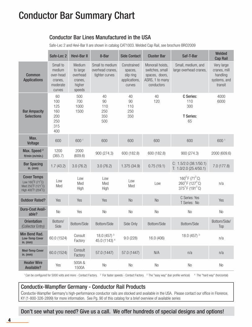
Conductor Bar Summary Chart
Don’t see what you need? Give us a call. We offer hundreds of special designs and options!
Conductor Bar Lines Manufactured in the USASafe-Lec 2 and Hevi-Bar II are shown in catalog CAT1003. Welded Cap Rail, see brochure BRO2009
Safe-Lec 2 Hevi-Bar II 8-Bar Side Contact Cluster Bar Saf-T-BarWeldedCap Rail
Common Applications
Small to medium
over-head cranes,
moderate curves
Medium to large
overhead cranes, higher speeds
Small to medium overhead cranes,
tighter curves
Constrained spaces, slip ring
applications, curves
Monorail hoists, switches, small spaces, doors,
ASRS, 1 to many conductors
Small, medium, and large overhead cranes,
Very large cranes, mill
handling systems, and
transit
Bar AmpacitySelections
60100125 160200250315400
50070010001500
4090
110250350500
4090110250350
40120
C Series: 110300
T Series:65
40006000
Max.Voltage
600 600 1 600 600 600 600 600 1
Max. Speed 2
ft/min (m/min.)
1200 (365.7)
2000 (609.6)
900 (274.3) 600 (182.8) 600 (182.8) 900 (274.3) 2000 (609.6)
Bar Spacingin. (mm)
1.7 (43.2) 3.0 (76.2) 3.0 (76.2) 1.375 (34.9) 0.75 (19.1)C: 1.5/2.0 (38.1/50.1)T: 1.0/2.0 (25.4/50.1)
7.0 (177.8)
Cover TempsLow 160
OF (71
OC)
Med 250OF (121
OC)
High 400OF (204
OC)
LowMed
LowMedHigh
LowMedHigh
LowMed
Low160O F (71O C)260O F (127O C)375O F (191O C)
n/a
Outdoor Rated? Yes Yes Yes No NoC Series: YesT Series: No
Yes
Dura-Coat Avail-able?
No Yes No No No No No
Orientation(Collector Entry)
Bottom/Side
Bottom/Side Bottom/Side Side Only Bottom/Side Bottom/SideBottom/Side/
Top
Min Bend Rad.Low-Temp Coverin. (mm)
60.0 (1524)Consult Factory
18.0 (457) 3
45.0 (1143) 4 9.0 (228) 16.0 (406)18.0 (457) 3
n/a
Med-Temp Coverin. (mm) 60.0 (1524)
Consult Factory
57.0 (1447) 57.0 (1447) N/A n/a n/a
Heater WireAvailable?
Yes500A & 1500A
No No No No No
1 Can be configured for 5000 volts and more - Contact Factory. 2 For faster speeds - Contact Factory. 3 The "easy way" (bar profile vertical) 4 The "hard way" (horizontal)
Conductix-Wampfler Germany - Conductor Rail ProductsConductix-Wampfler Germany's high-performance conductor rails are stocked and available in the USA. Please contact our office in Florence, KY (1-800-326-2899) for more information. See Pg. 90 of this catalog for a brief overview of available series
5
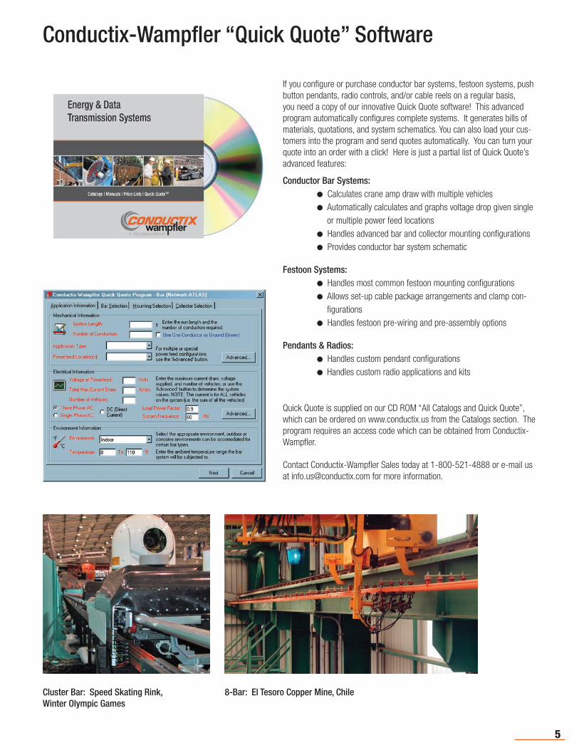
Conductix-Wampfler “Quick Quote” Software
If you configure or purchase conductor bar systems, festoon systems, push button pendants, radio controls, and/or cable reels on a regular basis, you need a copy of our innovative Quick Quote software! This advanced program automatically configures complete systems. It generates bills of materials, quotations, and system schematics. You can also load your cus-tomers into the program and send quotes automatically. You can turn your quote into an order with a click! Here is just a partial list of Quick Quote’s advanced features:
Conductor Bar Systems: l Calculates crane amp draw with multiple vehicles l Automatically calculates and graphs voltage drop given single
or multiple power feed locations l Handles advanced bar and collector mounting configurations l Provides conductor bar system schematic
Festoon Systems: l Handles most common festoon mounting configurations l Allows set-up cable package arrangements and clamp con-
figurations l Handles festoon pre-wiring and pre-assembly options
Pendants & Radios: l Handles custom pendant configurations lHandles custom radio applications and kits
Quick Quote is supplied on our CD ROM “All Catalogs and Quick Quote”, which can be ordered on www.conductix.us from the Catalogs section. The program requires an access code which can be obtained from Conductix-Wampfler.
Contact Conductix-Wampfler Sales today at 1-800-521-4888 or e-mail us at [email protected] for more information.
Cluster Bar: Speed Skating Rink, Winter Olympic Games
8-Bar: El Tesoro Copper Mine, Chile

6
Conductor Bar Specification Data Sheet
ENVIRONMENTAL DATA Describe the environment where the conductor system will be located:
1. Indoors Outdoors Both Indoors and Outdoors Outdoor & Ice
2. Ambient temperature range Min Max Degrees Fahrenheit Celsius
3. Will a heater wire need to be included? Yes No (If yes, consult factory)
4. Is there a source of corrosion present? Yes No
If yes, describe the corrosive:
5. Other environmental considerations (dust, etc.)?
APPLICATION1. Application Type: Runway Bridge Monorail Other
2. New Approved Installation? Extended Existing? Replacement?
3. System Length: Feet Meters
4. Total Number of Conductors: Will one conductor be designated as a ground? Yes No
MECHANICAL DATA 1. Vehicle Speed Feet/Min M/Min Duty Cycle
2. Number of vehicles or trolleys Crane Class (if applicable)
Refer to Appendix I Pg. 83-86.
3. Will Conductix-Wampfler be supplying mounting brackets? Yes No
4. Does the system include any curves? Yes No (if yes, consult factory)
5. Other mechanical notes:
ELECTRICAL SPECIFICATIONS 1. Number of power feeds
2. Location of power feeds (check all that apply): Center Multiple End
Advanced: Distance power feeds will be from end of system (or attach diagram)
3. Number of power phases Operating voltage (volts) AC DC
4. Total current draw (sum of all vehicles ) (Amps) Demand factor (typically .9)
5. Operating Frequency (Hz - USA is 60 Hz) (Refer to chart on Pg. 7 for multiple cranes)
Refer to Appendix I Pg. 83.
Refer to Appendix I Pg. 84.
Fax to: 800-780-8329 or 402-339-9627 E-mail to: [email protected]
Contact Conductix-Wampfler today to discuss your Conductor Bar application.
Request Date Sales Person
Company Name
Title
Phone
Fax
Company Type E-mail

7
Sizing systems for multiple hoists, motors, and/or multiple cranes For a single crane: Size the conductor bar to handle 100% of the current draw of the largest motor or
group of motors, plus 50% of the combined current draw of the other motors on the vehicle.
For multiple cranes or vehicles: Determine the current draw for each crane/vehicle, using the method
above. Sum all the current draws for each crane/vehicle, then multiply the sum by the appropriate demand factor:
# of Cranes/vehicles Demand Factor
2 .95
3 .91
4 .87
5 .84
6 .81
7 .78
Conductor Bar Specification Data Sheet
8-Bar: An excellent choice for tightly curved systems

8
8-BarThe first insulated conductor system for crane/monorail electrification. If you need 8-bar, insist on the original! Many accessories available. Able to accommodate small bend radii for curved systems and slip rings. 40A, 90A, 110A, 250A, 350A, and 500A capacity bars.
UL / CSA Listed R
Cluster BarA compact "finger safe" (IP2) system featuring 3/4” minimum spacing between bars. Ideal for small cranes, material handling applications, and automated storage and retrieval systems. Can accommodate bottom or lateral entry and can be bent to a small radii for curved systems and slip rings. 40A and 120A capacity bars.
CSA Listed
Insul-8® 8-Bar, Side Contact, and Cluster Bar
Omaha Plant Harlan Plant
Conductix-Wampfler has designed and built state-
of-the-art conductor bar systems for over 60 years.
Our experienced engineering and sales people are
recognized experts in the application of conductor bar
systems to solve industrial problems.
The "Americas branch" of Conductix-Wampfler was
founded in 1944 as Insul-8 Corporation. Insul-8
developed the first “Figure 8” conductor bar system,
which became the standard method for electrifying
overhead cranes. In 1991 the company moved its
manufacturing facility to its current location in Harlan,
Iowa, USA.
Recent conductor bar innovations include the new
“finger-safe” Safe-Lec 2 V-contact bar and the
Hevi-Bar II conductor system with optional Dura-Coat
corrosion protection see catalog number CAT1003.
Conductix-Wampfler 8-Bar, Side Contact, and
Cluster Bar are manufactured in the USA to provide
quick delivery, many configurations and options,
and competitive prices. All Conductix manufacturing
facilities are ISO 9001:2000 certified. Our stringent
quality systems assure that you will get the right
product every time.
We offer a complete complement of mobile
electrification products including Cable Festoon
Systems, Cable Reels (spring and motorized), Push-
Button Pendants, Radio Remote Controls, and Crane
Bumpers - See Pg. 91.
In 2006, the company, part of the Delachaux
Group since 1975, was renamed “Conductix". With
the merger of Conductix and Wampfler in 2007,
Conductix-Wampfler is now the world leader in
the design and manufacture of high-performance
conductor bar systems for industrial applications.
Safe-Lec 2 and Hevi-Bar IIFor details on the Safe-Lec 2 and Hevi Bar II conductor bar, please refer to catalog CAT1003.
Series 811, 812, 813, 815, 832, 842For details on conductor bar products manufactured by Conductix-Wampfler Germany, please refer to catalog KAT0***-0001-US (*** = series no.)
Side ContactSimilar in construction to 8-Bar, Side Contact is the appropriate system for constrained spaces and difficult installations. Side contact can accommodate very small bend radii for curved systems and slip rings. 40A, 90A, 110A, 250A, and 350A capacity bars.
UL / CSA Listed R
R

9
Insul-8® 8-Bar Design Features
Conductix-Wampfler "Insul-8® 8-Bar"was invented by Insul-8 Cor-poration over 60 years ago. This is the original “figure 8” conductor bar system! This innovative system provided the first safe, insulated elec-trification solution for cranes, monorails, hoists, conveyors, and many other applications. Thousands of miles of 8-Bar are in use all around the world. There are many “copy cat” systems around. Don’t settle for imitations; insist on the original 8-Bar system!
UL and CSA ListedR
Features• Designed and built in the USA under stringent ISO 9001:2000 standard
• In stock availability for quick shipment• A large number of special options and adaptations
developed over 60 years of usage to handle numerous industrial situations.
• The ability to be curved into a tighter radius than most other systems.
• Knurled joint pins for secure joints. Won’t pull apart under normal conditions when properly installed.
• Backed by the best customer service and engineering services in the industry.
Installs Quickly and Easily• Minimum number of basic parts• Quick “pin-style” splice joints • Bar snaps into mating hanger
Many Options• Stainless steel hardware
• Green bonding (ground) conductor covers
• Black “UV stable” outdoor covers
• Curved systems with low heat cover; can be curved to 18” minimum radius with the bar profile vertical (i.e. the "easy” way) or 45” the “hard way” (low heat cover).
Current range: 40A, 90A, 110A, 250A, 350A, 500A @ 600 volts max.
Maximum Speed: 900 ft/min (274 meters/min)
Power Feed: Conducts the power source to the conductor bar
Collector: “ Collects” power from the bar and transfers it to the moving machine. Connects to a 1” mounting staff
Hanger Clamp: Supports the conductor bar
End Cover: Caps off the end of the conductor bar
Bracket: Attaches to crane beam or other structure to support multiple hangers
Anchor Clamp: Connects the bar to the structure and directs movement of the conductors during thermal expansion/contraction
End CoverPower Feed Hanger Clamp
8-BarConductor
1” SquareBar Collector
Automate your work with our advanced “Quick Quote” software - See Pg. 5.
Insul-8® 8-Bar is Ideal for: • Small/Medium sized cranes • Hoists
• Conveyors • Tightly curved systems
• Monorails • Other mobile power applications
Basic 8-Bar Components
10
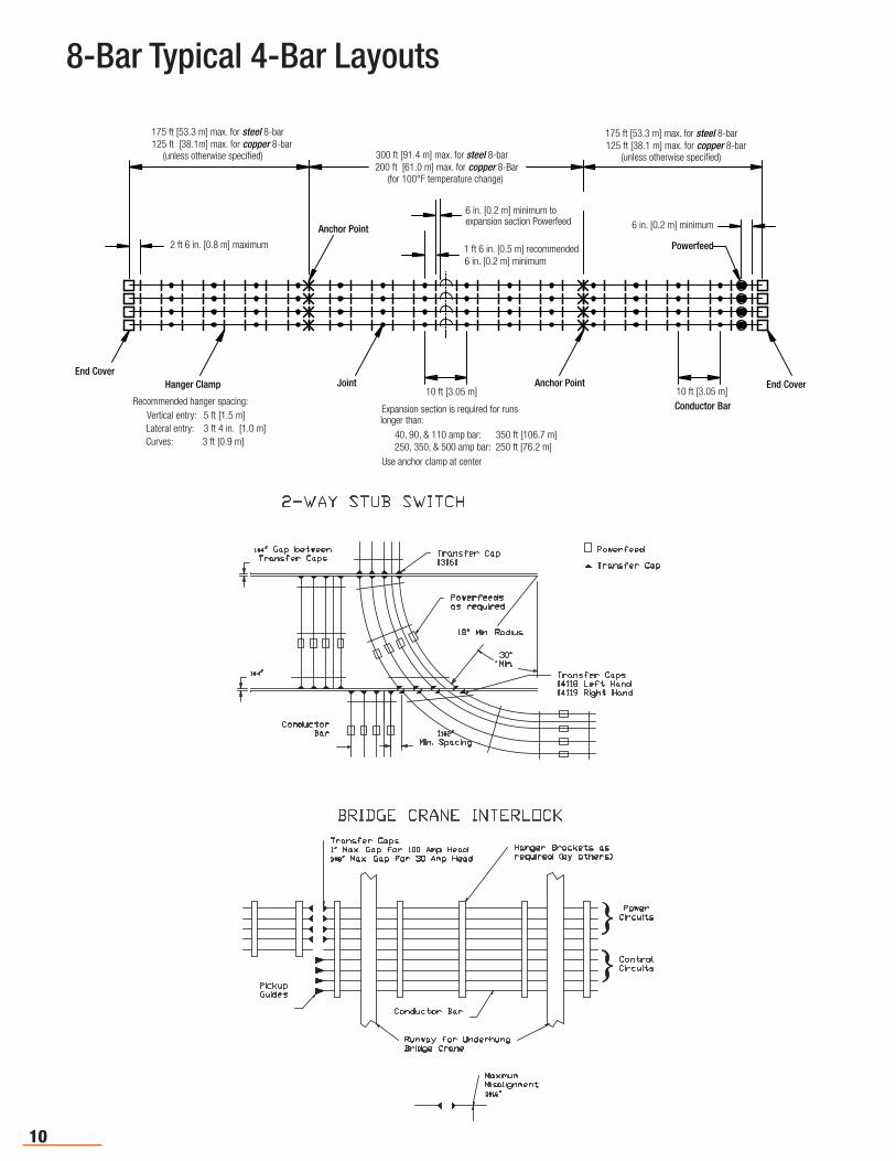
8-Bar Typical 4-Bar Layouts
11#2"Min. Spacing
ConductorBar
18" Min. Radius
Powerfeedsas required
30°Min.
Powerfeed
Transfer CapTransfer Cap13161
Transfer Caps14118 Left Hand14119 Right Hand
1#4" Gap betweenTransfer Caps
1#4"
2-WAY STUB SWITCHBRIDGE CRANE INTERLOCK
PickupGuides
MaximumMisalignment3#16"
Transfer Caps 1" Max. Gap for 100 Amp Head3#8" Max. Gap for 30 Amp Head
Hanger Brackets asrequired (by others)
Conductor Bar
Runway for UnderhungBridge Crane
}}
PowerCircuits
ControlCircuits
2 ft 6 in. [0.8 m] maximum 1 ft 6 in. [0.5 m] recommended6 in. [0.2 m] minimum
6 in. [0.2 m] minimum toexpansion section Powerfeed
300 ft [91.4 m] max. for steel 8-bar200 ft [61.0 m] max. for copper 8-Bar
(for 100°F temperature change)
Anchor Point
175 ft [53.3 m] max. for steel 8-bar 125 ft [38.1m] max. for copper 8-bar
(unless otherwise specified)
175 ft [53.3 m] max. for steel 8-bar125 ft [38.1 m] max. for copper 8-bar
(unless otherwise specified)
6 in. [0.2 m] minimum
Powerfeed
End CoverHanger Clamp
Recommended hanger spacing:Vertical entry: 5 ft [1.5 m]
Curves: 3 ft [0.9 m]Lateral entry: 3 ft 4 in. [1.0 m]
Joint10 ft [3.05 m]
Expansion section is required for runslonger than:
40, 90, & 110 amp bar: 350 ft [106.7 m]250, 350, & 500 amp bar: 250 ft [76.2 m]
Use anchor clamp at center
Anchor Point10 ft [3.05 m]
Conductor Bar
End Cover

11
8-Bar Specifications
Conductor Bar Information
Roll formed of 1/16” (1.59 mm) material except laminates which are 1/32” (0.79 mm) copper, steel, or stainless steel, and the 90 A galvanized bar. The cross-section area is 188 mcm (95 mm2 ); except solid copper bar which is 313 mcm (158 mm2 ). The equivalent rectangle for all conductors is 1” x 1/4” (25.4 x 6.3 mm). Supports are required every 3 feet (0.91m) for curves, 3 feet 4 inches (1.01m) for lateral mount, and 5 feet (1.52m) standard.
Please use the Specification Data Sheets on Pgs. 6-7 and the information in Appendices I through III at the back of this catalog to determine your conductor bar needs. Consult Conductix-Wampfler Sales if you have any questions about the suitability of this product to your application.
Part No. 11000
120 (3048)
118.5 (3010)0.75(19.1)
0.5625(14.3)
1.375(34.9)
Assembled with Connector Pins and CoverMicro-ohms per foot *
Part No.
MaterialLgthft (m)
w/PVCCover
w/Med Heat Cover
w/High HeatCover
ExpansionCoefficientin./in./0F
NominalWt lb/ft(kg/m)
Max.Amps(contduty)
Resist.R (DC)
Reac-tance
X (60 Hz, 3-phase
Imp. Z (60 Hz)
Stainless Steel 10 (3.05) 14299 24304 24307 .000007 0.72 ( 0.0995) 40 2230 60 2231
Galvanized Steel 10 (3.05) 22135 22141 22147 .000007 0.46 (0.0636) 90 750 600 960
Galvanized Steel 10 (3.05) 11000 11019 11038 .000007 0.65 (0.0899) 110 354 600 702
Stainless CladCopper Laminate
10 (3.05) 11004 11023 11042 .000009 0.65 (0.0899) 250 100 60 116
Copper Steel Laminate
10 (3.05) 11008 11027 11046 .000009 0.65 ( 0.0899) 250 100 60 116
Rolled Copper 10 (3.05) 11012 11031 11050 .000009 0.76 ( 0.1051) 350 60 60 84
Solid Copper 20 (6.10) 11016 11035 11054 .000009 1.16 ( 0.5262) 500 40 60 70
Q Example: 0.000060 ohms/ft. X values are calculated at 3 inch center-line spacing, adjusted for three conductors with multiplier 1:26 a nominal permeability m of 10-12 is used for the steel conductor calculations. For reference, X = m 52.9 log 10 3 x 1.26 + 34.5. Z = R2 1 X3
1250
12
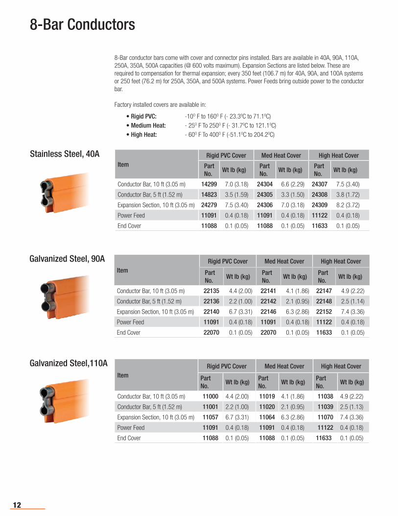
8-Bar Conductors
Stainless Steel, 40AItem
Rigid PVC Cover Med Heat Cover High Heat Cover
PartNo.
Wt lb (kg)PartNo.
Wt lb (kg)PartNo.
Wt lb (kg)
Conductor Bar, 10 ft (3.05 m) 14299 7.0 (3.18) 24304 6.6 (2.29) 24307 7.5 (3.40)
Conductor Bar, 5 ft (1.52 m) 14823 3.5 (1.59) 24305 3.3 (1.50) 24308 3.8 (1.72)
Expansion Section, 10 ft (3.05 m) 24279 7.5 (3.40) 24306 7.0 (3.18) 24309 8.2 (3.72)
Power Feed 11091 0.4 (0.18) 11091 0.4 (0.18) 11122 0.4 (0.18)
End Cover 11088 0.1 (0.05) 11088 0.1 (0.05) 11633 0.1 (0.05)
Galvanized Steel, 90AItem
Rigid PVC Cover Med Heat Cover High Heat Cover
PartNo.
Wt lb (kg)PartNo.
Wt lb (kg)PartNo.
Wt lb (kg)
Conductor Bar, 10 ft (3.05 m) 22135 4.4 (2.00) 22141 4.1 (1.86) 22147 4.9 (2.22)
Conductor Bar, 5 ft (1.52 m) 22136 2.2 (1.00) 22142 2.1 (0.95) 22148 2.5 (1.14)
Expansion Section, 10 ft (3.05 m) 22140 6.7 (3.31) 22146 6.3 (2.86) 22152 7.4 (3.36)
Power Feed 11091 0.4 (0.18) 11091 0.4 (0.18) 11122 0.4 (0.18)
End Cover 22070 0.1 (0.05) 22070 0.1 (0.05) 11633 0.1 (0.05)
ItemRigid PVC Cover Med Heat Cover High Heat Cover
PartNo.
Wt lb (kg)PartNo.
Wt lb (kg)PartNo.
Wt lb (kg)
Conductor Bar, 10 ft (3.05 m) 11000 4.4 (2.00) 11019 4.1 (1.86) 11038 4.9 (2.22)
Conductor Bar, 5 ft (1.52 m) 11001 2.2 (1.00) 11020 2.1 (0.95) 11039 2.5 (1.13)
Expansion Section, 10 ft (3.05 m) 11057 6.7 (3.31) 11064 6.3 (2.86) 11070 7.4 (3.36)
Power Feed 11091 0.4 (0.18) 11091 0.4 (0.18) 11122 0.4 (0.18)
End Cover 11088 0.1 (0.05) 11088 0.1 (0.05) 11633 0.1 (0.05)
Galvanized Steel,110A
8-Bar conductor bars come with cover and connector pins installed. Bars are available in 40A, 90A, 110A, 250A, 350A, 500A capacities (@ 600 volts maximum). Expansion Sections are listed below. These are required to compensation for thermal expansion; every 350 feet (106.7 m) for 40A, 90A, and 100A systems or 250 feet (76.2 m) for 250A, 350A, and 500A systems. Power Feeds bring outside power to the conductor bar.
Factory installed covers are available in:
• Rigid PVC: -10O F to 160O F (- 23.30C to 71.10C)• Medium Heat: - 25O F To 250O F (- 31.70C to 121.10C)• High Heat: - 60O F To 400O F (-51.10C to 204.20C)
13
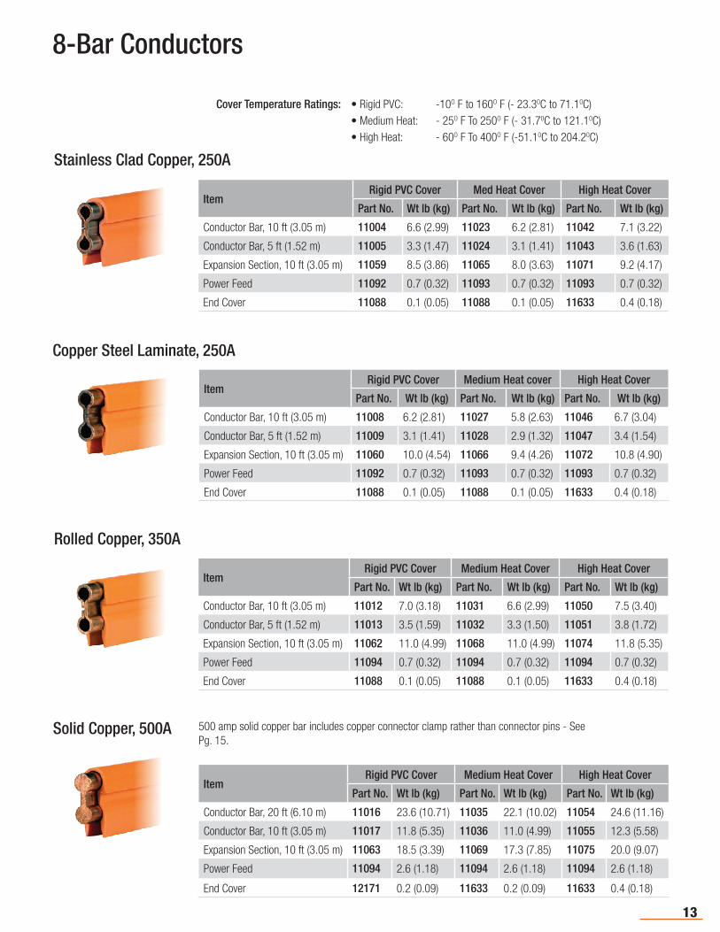
8-Bar Conductors
Copper Steel Laminate, 250A
ItemRigid PVC Cover Medium Heat cover High Heat Cover
Part No. Wt lb (kg) Part No. Wt lb (kg) Part No. Wt lb (kg)
Conductor Bar, 10 ft (3.05 m) 11008 6.2 (2.81) 11027 5.8 (2.63) 11046 6.7 (3.04)
Conductor Bar, 5 ft (1.52 m) 11009 3.1 (1.41) 11028 2.9 (1.32) 11047 3.4 (1.54)
Expansion Section, 10 ft (3.05 m) 11060 10.0 (4.54) 11066 9.4 (4.26) 11072 10.8 (4.90)
Power Feed 11092 0.7 (0.32) 11093 0.7 (0.32) 11093 0.7 (0.32)
End Cover 11088 0.1 (0.05) 11088 0.1 (0.05) 11633 0.4 (0.18)
Rolled Copper, 350A
ItemRigid PVC Cover Medium Heat Cover High Heat Cover
Part No. Wt lb (kg) Part No. Wt lb (kg) Part No. Wt lb (kg)
Conductor Bar, 10 ft (3.05 m) 11012 7.0 (3.18) 11031 6.6 (2.99) 11050 7.5 (3.40)
Conductor Bar, 5 ft (1.52 m) 11013 3.5 (1.59) 11032 3.3 (1.50) 11051 3.8 (1.72)
Expansion Section, 10 ft (3.05 m) 11062 11.0 (4.99) 11068 11.0 (4.99) 11074 11.8 (5.35)
Power Feed 11094 0.7 (0.32) 11094 0.7 (0.32) 11094 0.7 (0.32)
End Cover 11088 0.1 (0.05) 11088 0.1 (0.05) 11633 0.4 (0.18)
Solid Copper, 500A
ItemRigid PVC Cover Medium Heat Cover High Heat Cover
Part No. Wt lb (kg) Part No. Wt lb (kg) Part No. Wt lb (kg)
Conductor Bar, 20 ft (6.10 m) 11016 23.6 (10.71) 11035 22.1 (10.02) 11054 24.6 (11.16)
Conductor Bar, 10 ft (3.05 m) 11017 11.8 (5.35) 11036 11.0 (4.99) 11055 12.3 (5.58)
Expansion Section, 10 ft (3.05 m) 11063 18.5 (3.39) 11069 17.3 (7.85) 11075 20.0 (9.07)
Power Feed 11094 2.6 (1.18) 11094 2.6 (1.18) 11094 2.6 (1.18)
End Cover 12171 0.2 (0.09) 11633 0.2 (0.09) 11633 0.4 (0.18)
Stainless Clad Copper, 250A
ItemRigid PVC Cover Med Heat Cover High Heat Cover
Part No. Wt lb (kg) Part No. Wt lb (kg) Part No. Wt lb (kg)
Conductor Bar, 10 ft (3.05 m) 11004 6.6 (2.99) 11023 6.2 (2.81) 11042 7.1 (3.22)
Conductor Bar, 5 ft (1.52 m) 11005 3.3 (1.47) 11024 3.1 (1.41) 11043 3.6 (1.63)
Expansion Section, 10 ft (3.05 m) 11059 8.5 (3.86) 11065 8.0 (3.63) 11071 9.2 (4.17)
Power Feed 11092 0.7 (0.32) 11093 0.7 (0.32) 11093 0.7 (0.32)
End Cover 11088 0.1 (0.05) 11088 0.1 (0.05) 11633 0.4 (0.18)
• Rigid PVC: -10O F to 160O F (- 23.30C to 71.10C)• Medium Heat: - 25O F To 250O F (- 31.70C to 121.10C)• High Heat: - 60O F To 400O F (-51.10C to 204.20C)
500 amp solid copper bar includes copper connector clamp rather than connector pins - See Pg. 15.
Cover Temperature Ratings:
14
8-Bar Replacement Covers, Connectors, & Joint Covers
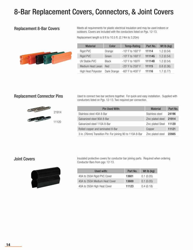
Replacement 8-Bar Covers Meets all requirements for plastic electrical insulation and may be used indoors or outdoors. Covers are included with the conductors listed on Pgs. 12-13.
Replacement length is 9 ft to 10.5 ft. (2.74m to 3.20m)
Material Color Temp-Rating Part No. Wt lb (kg)
Rigid PVC Orange -10O F to 160O F 11114 1.2 (0.54)
Rigid PVC Green -10O F to 160O F 11114G 1.2 (0.54)
UV Stable PVC Black -10O F to 160OF 11114B 1.2 (0.54)
Medium Heat Lexan Red -25O F to 250O F 11115 0.8 (0.36)
High Heat Polyester Dark Orange -60O F to 400O F 11116 1.7 (0.77)
Replacement Connector Pins Used to connect two bar sections together. For quick and easy installation. Supplied with conductors listed on Pgs. 12-13. Two required per connection.
Pin Used With: Material Part No.
Stainless steel 40A 8-Bar Stainless steel 24196
Galvanized steel 90A 8-Bar Zinc plated steel 21914
Galvanized steel 110A 8-Bar Zinc plated Steel 11120
Rolled copper and laminated 8-Bar Copper 11121
3 in. (76mm) Transition Pin: For joining 90 to 110A 8-Bar Zinc plated steel 22885
21914
11120
Joint Covers Insulated protective covers for conductor bar joining parts. Required when ordering Conductor Bars from pgs: 12-13.
Used with: Part No. Wt lb (kg)
40A to 350A Rigid PVC Cover 13601 0.1 (0.05)
40A to 350A Medium Heat Cover 13600 0.1 (0.05)
40A to 350A High Heat Cover 11123 0.4 (0.18)
15
8-Bar Joint Parts & Tools
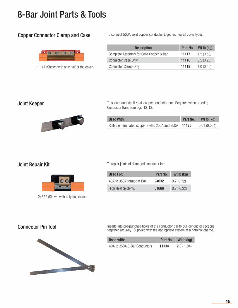
Copper Connector Clamp and Case To connect 500A solid copper conductor together. For all cover types.
Description Part No. Wt lb (kg)
Complete Assembly for Solid Copper 8-Bar 11117 1.5 (0.68)
Connector Case Only 11118 0.5 (0.23)
Connector Clamp Only 11119 1.0 (0.45)11117 (Shown with only half of the cover)
Joint Keeper To secure and stabilize all copper conductor bar. Required when ordering Conductor Bars from pgs: 12-13.
Used With: Part No. Wt lb (kg)
Rolled or laminated copper 8-Bar, 250A and 350A 11125 0.01 (0.004)
Joint Repair Kit To repair joints of damaged conductor bar.
Used For: Part No. Wt lb (kg)
40A to 350A formed 8-Bar 24632 0.7 (0.32)
High Heat Systems 51666 0.7 (0.32)
Connector Pin Tool
Used with: Part No. Wt lb (kg)
40A to 350A 8-Bar Conductors 11134 2.3 ( 1.04)
Inserts into pre-punched holes of the conductor bar to pull conductor sections together securely. Supplied with the appropriate system at a nominal charge.
24632 (Shown with only half cover)
16
8-Bar End Covers & Power Feeds
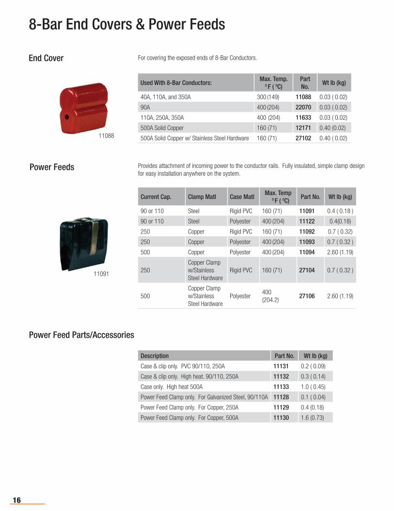
For covering the exposed ends of 8-Bar Conductors.
Used With 8-Bar Conductors:Max. Temp.
0 F ( 0C)Part No.
Wt lb (kg)
40A, 110A, and 350A 300 (149) 11088 0.03 ( 0.02)
90A 400 (204) 22070 0.03 ( 0.02)
110A, 250A, 350A 400 (204) 11633 0.03 ( 0.02)
500A Solid Copper 160 (71) 12171 0.40 (0.02)
500A Solid Copper w/ Stainless Steel Hardware 160 (71) 27102 0.40 ( 0.02)11088
End Cover
Power Feeds Provides attachment of incoming power to the conductor rails. Fully insulated, simple clamp design for easy installation anywhere on the system.
Current Cap. Clamp Matl Case MatlMax. Temp
0 F ( 0C)Part No. Wt lb (kg)
90 or 110 Steel Rigid PVC 160 (71) 11091 0.4 ( 0.18 )
90 or 110 Steel Polyester 400 (204) 11122 0.4(0.18)
250 Copper Rigid PVC 160 (71) 11092 0.7 ( 0.32)
250 Copper Polyester 400 (204) 11093 0.7 ( 0.32 )
500 Copper Polyester 400 (204) 11094 2.60 (1.19)
250Copper Clamp w/Stainless Steel Hardware
Rigid PVC 160 (71) 27104 0.7 ( 0.32 )
500 Copper Clamp w/Stainless Steel Hardware
Polyester400
(204.2)27106 2.60 (1.19)
11091
Description Part No. Wt lb (kg)
Case & clip only. PVC 90/110, 250A 11131 0.2 ( 0.09)
Case & clip only. High heat. 90/110, 250A 11132 0.3 ( 0.14)
Case only. High heat 500A 11133 1.0 ( 0.45)
Power Feed Clamp only. For Galvanized Steel, 90/110A 11128 0.1 ( 0.04)
Power Feed Clamp only. For Copper, 250A 11129 0.4 (0.18)
Power Feed Clamp only. For Copper, 500A 11130 1.6 (0.73)
Power Feed Parts/Accessories
17
8-Bar Expansions & Isolation Sections
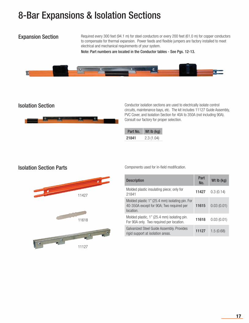
Expansion Section Required every 300 feet (94.1 m) for steel conductors or every 200 feet (61.0 m) for copper conductors to compensate for thermal expansion. Power feeds and flexible jumpers are factory installed to meet electrical and mechanical requirements of your system.Note: Part numbers are located in the Conductor tables - See Pgs. 12-13.
Isolation Section Conductor isolation sections are used to electrically isolate control circuits, maintenance bays, etc. The kit includes 11127 Guide Assembly, PVC Cover, and Isolation Section for 40A to 350A (not including 90A). Consult our factory for proper selection.
Isolation Section Parts Components used for in-field modification.
DescriptionPart No.
Wt lb (kg)
Molded plastic insulating piece; only for 21841
11427 0.3 (0.14)
Molded plastic 1” (25.4 mm) isolating pin. For 40-350A except for 90A; Two required per location.
11615 0.03 (0.01)
Molded plastic, 1” (25.4 mm) isolating pin. For 90A only. Two required per location.
11618 0.03 (0.01)
Galvanized Steel Guide Assembly. Provides rigid support at isolation areas.
11127 1.5 (0.68)
Part No. Wt lb (kg)
21841 2.3 (1.04)
11427
11618
11127
18
8-Bar Transfer Caps, Pickup Guides, Collector Brackets
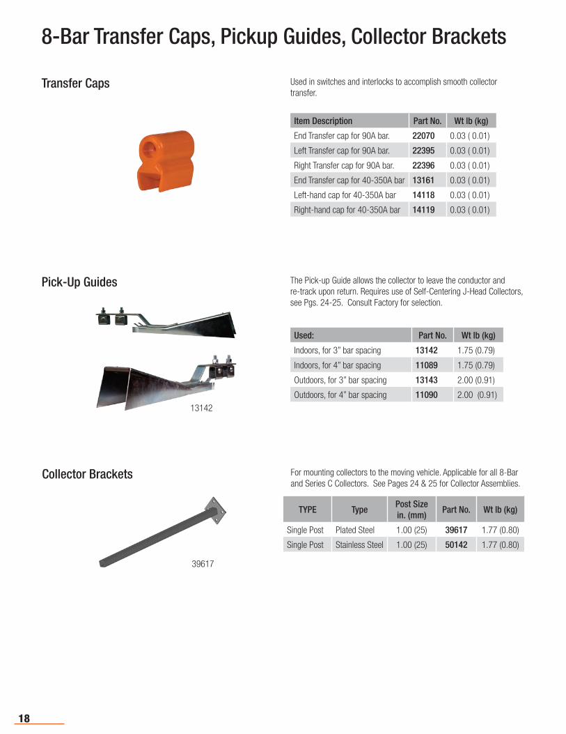
Transfer Caps Used in switches and interlocks to accomplish smooth collector transfer.
Item Description Part No. Wt lb (kg)
End Transfer cap for 90A bar. 22070 0.03 ( 0.01)
Left Transfer cap for 90A bar. 22395 0.03 ( 0.01)
Right Transfer cap for 90A bar. 22396 0.03 ( 0.01)
End Transfer cap for 40-350A bar 13161 0.03 ( 0.01)
Left-hand cap for 40-350A bar 14118 0.03 ( 0.01)
Right-hand cap for 40-350A bar 14119 0.03 ( 0.01)
Pick-Up Guides The Pick-up Guide allows the collector to leave the conductor and re-track upon return. Requires use of Self-Centering J-Head Collectors, see Pgs. 24-25. Consult Factory for selection.
Used: Part No. Wt lb (kg)
Indoors, for 3” bar spacing 13142 1.75 (0.79)
Indoors, for 4” bar spacing 11089 1.75 (0.79)
Outdoors, for 3” bar spacing 13143 2.00 (0.91)
Outdoors, for 4” bar spacing 11090 2.00 (0.91)
13142
Collector Brackets For mounting collectors to the moving vehicle. Applicable for all 8-Bar and Series C Collectors. See Pages 24 & 25 for Collector Assemblies.
39617
TYPE TypePost Size in. (mm)
Part No. Wt lb (kg)
Single Post Plated Steel 1.00 (25) 39617 1.77 (0.80)
Single Post Stainless Steel 1.00 (25) 50142 1.77 (0.80)
19
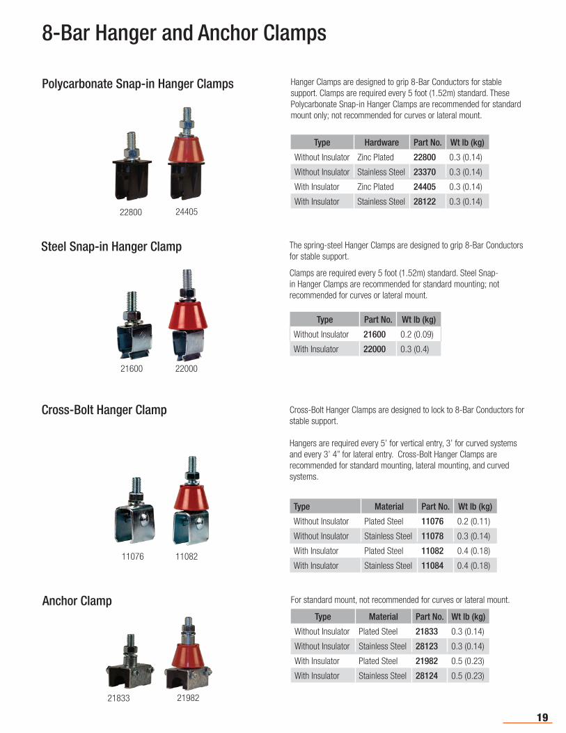
Polycarbonate Snap-in Hanger Clamps Hanger Clamps are designed to grip 8-Bar Conductors for stable support. Clamps are required every 5 foot (1.52m) standard. These Polycarbonate Snap-in Hanger Clamps are recommended for standard mount only; not recommended for curves or lateral mount.
Type Hardware Part No. Wt lb (kg)
Without Insulator Zinc Plated 22800 0.3 (0.14)
Without Insulator Stainless Steel 23370 0.3 (0.14)
With Insulator Zinc Plated 24405 0.3 (0.14)
With Insulator Stainless Steel 28122 0.3 (0.14)2440522800
8-Bar Hanger and Anchor Clamps
Steel Snap-in Hanger Clamp The spring-steel Hanger Clamps are designed to grip 8-Bar Conductors for stable support.
Clamps are required every 5 foot (1.52m) standard. Steel Snap-in Hanger Clamps are recommended for standard mounting; not recommended for curves or lateral mount.
Type Part No. Wt lb (kg)
Without Insulator 21600 0.2 (0.09)
With Insulator 22000 0.3 (0.4)
Cross-Bolt Hanger Clamp Cross-Bolt Hanger Clamps are designed to lock to 8-Bar Conductors for stable support.
Hangers are required every 5’ for vertical entry, 3’ for curved systems and every 3’ 4” for lateral entry. Cross-Bolt Hanger Clamps are recommended for standard mounting, lateral mounting, and curved systems.
Type Material Part No. Wt lb (kg)
Without Insulator Plated Steel 11076 0.2 (0.11)
Without Insulator Stainless Steel 11078 0.3 (0.14)
With Insulator Plated Steel 11082 0.4 (0.18)
With Insulator Stainless Steel 11084 0.4 (0.18)
Anchor Clamp For standard mount, not recommended for curves or lateral mount.
Type Material Part No. Wt lb (kg)
Without Insulator Plated Steel 21833 0.3 (0.14)
Without Insulator Stainless Steel 28123 0.3 (0.14)
With Insulator Plated Steel 21982 0.5 (0.23)
With Insulator Stainless Steel 28124 0.5 (0.23)
2200021600
1108211076
2198221833
TYPE TypePost Size in. (mm)
Part No. Wt lb (kg)
Single Post Plated Steel 1.00 (25) 39617 1.77 (0.80)
Single Post Stainless Steel 1.00 (25) 50142 1.77 (0.80)

20
Web Bracket
Distance to First Hole: Part No. Wt lb (kg)
6.0 (152) 22014 2.4 (1.09)
9.0 (229); with three more holes - At 12.0 (305), 15 (381), and 18 (457)
29876 4.5 (2.04)22014
For top running, web-mounted, bottom entry systems. Zinc plated steel. See Pg. 19 for hangers.
8-Bar Standard Brackets - Without Hangers
Flange Mount Brackets
27762
Type Part No. Wt lb (kg)
For 2 hangers each side 27762 2.5 (1.13)
For 4 hangers on one side 27767 2.5 (1.13)
For bottom entry monorail and under-hung systems, flange-mounted. Zinc plated steel. See Pg. 19 for hangers.
21
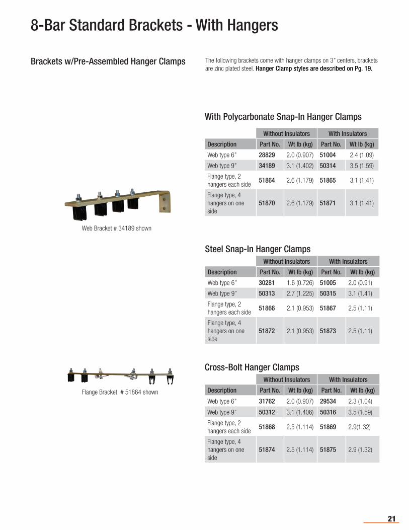
Brackets w/Pre-Assembled Hanger Clamps The following brackets come with hanger clamps on 3” centers, brackets are zinc plated steel. Hanger Clamp styles are described on Pg. 19.
Steel Snap-In Hanger ClampsWithout Insulators With Insulators
Description Part No. Wt lb (kg) Part No. Wt lb (kg)
Web type 6” 30281 1.6 (0.726) 51005 2.0 (0.91)
Web type 9” 50313 2.7 (1.225) 50315 3.1 (1.41)
Flange type, 2 hangers each side
51866 2.1 (0.953) 51867 2.5 (1.11)
Flange type, 4 hangers on one side
51872 2.1 (0.953) 51873 2.5 (1.11)
Cross-Bolt Hanger ClampsWithout Insulators With Insulators
Description Part No. Wt lb (kg) Part No. Wt lb (kg)
Web type 6” 31762 2.0 (0.907) 29534 2.3 (1.04)
Web type 9” 50312 3.1 (1.406) 50316 3.5 (1.59)
Flange type, 2 hangers each side
51868 2.5 (1.114) 51869 2.9(1.32)
Flange type, 4 hangers on one side
51874 2.5 (1.114) 51875 2.9 (1.32)
With Polycarbonate Snap-In Hanger Clamps
Without Insulators With Insulators
Description Part No. Wt lb (kg) Part No. Wt lb (kg)
Web type 6” 28829 2.0 (0.907) 51004 2.4 (1.09)
Web type 9” 34189 3.1 (1.402) 50314 3.5 (1.59)
Flange type, 2 hangers each side
51864 2.6 (1.179) 51865 3.1 (1.41)
Flange type, 4hangers on one side
51870 2.6 (1.179) 51871 3.1 (1.41)
Web Bracket # 34189 shown
Flange Bracket # 51864 shown
8-Bar Standard Brackets - With Hangers
22
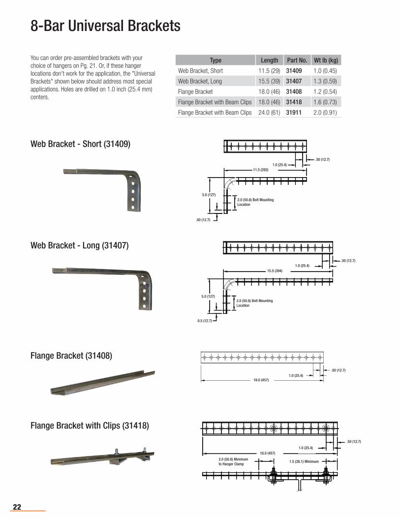
Web Bracket - Short (31409)
8-Bar Universal Brackets
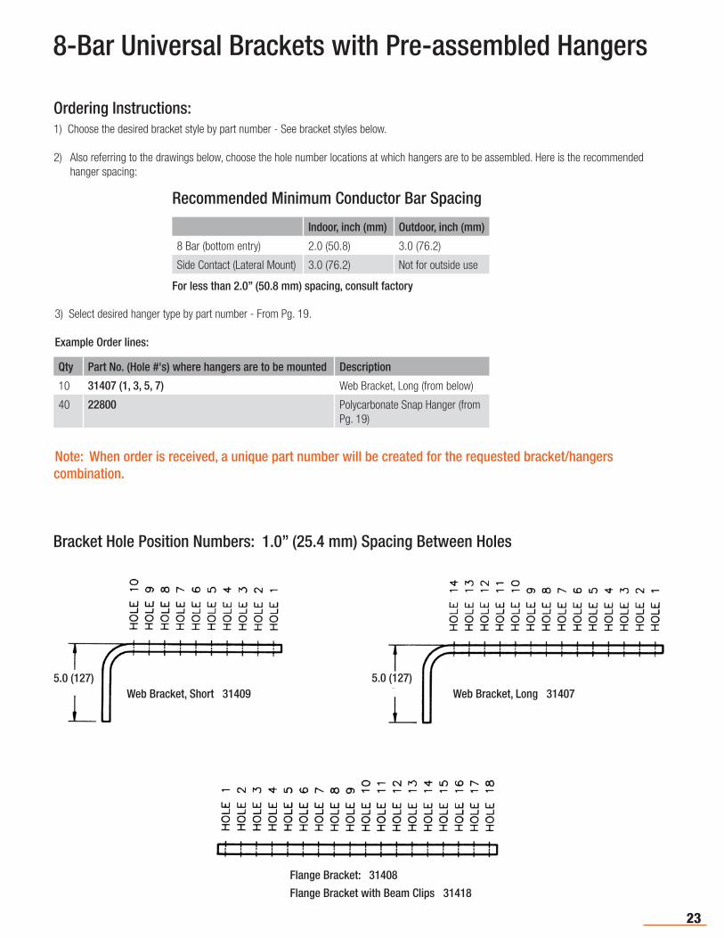
Type Length Part No. Wt lb (kg)
Web Bracket, Short 11.5 (29) 31409 1.0 (0.45)
Web Bracket, Long 15.5 (39) 31407 1.3 (0.59)
Flange Bracket 18.0 (46) 31408 1.2 (0.54)
Flange Bracket with Beam Clips 18.0 (46) 31418 1.6 (0.73)
Flange Bracket with Beam Clips 24.0 (61) 31911 2.0 (0.91)
Flange Bracket with Clips (31418)
You can order pre-assembled brackets with your choice of hangers on Pg. 21. Or, if these hanger locations don't work for the application, the "Universal Brackets" shown below should address most special applications. Holes are drilled on 1.0 inch (25.4 mm) centers.
Web Bracket - Long (31407)
Flange Bracket (31408)
11.5 [292.1]
0.5 [12.7]
1.0 [25.4]
0.5 [12.7]
5.0 [127.0]2.0 [50.8]
BOLT MOUNTINGLOCATION
.50 (12.7)
5.0 (127)
.50 (12.7)
11.5 (292)1.0 (25.4)
2.0 (50.8) Bolt MountingLocation
0.5 [12.7]
1.0 [25.4]
18.0 [457.2]
.50 (12.7)1.0 (25.4)
18.0 (457)
18.0 [457.2]
1.0 [25.4]
0.5 [12.7]
1.5 [38.1]MIN.
2.0 [50.8] MIN.TO HANGER CLAMP
.50 (12.7)
1.0 (25.4)
1.5 (38.1) Minimum
18.0 (457)
2.0 (50.8) Minimumto Hanger Clamp
15.5 [393.7]
0.5 [12.7]
1.0 [25.4]
0.5 [12.7]
5.0 [127.0]2.0 [50.8]
BOLT MOUNTINGLOCATION
.50 (12.7)
5.0 (127)
15.5 (394)
2.0 (50.8) Bolt MountingLocation
1.0 (25.4)
0.5 (12.7)
23
1) Choose the desired bracket style by part number - See bracket styles below.
2) Also referring to the drawings below, choose the hole number locations at which hangers are to be assembled. Here is the recommended hanger spacing:
3) Select desired hanger type by part number - From Pg. 19.
Example Order lines:
Qty Part No. (Hole #'s) where hangers are to be mounted Description
10 31407 (1, 3, 5, 7) Web Bracket, Long (from below)
40 22800 Polycarbonate Snap Hanger (from Pg. 19)
Note: When order is received, a unique part number will be created for the requested bracket/hangers combination.
8-Bar Universal Brackets with Pre-assembled Hangers
Ordering Instructions:
Recommended Minimum Conductor Bar Spacing
Indoor, inch (mm) Outdoor, inch (mm)
8 Bar (bottom entry) 2.0 (50.8) 3.0 (76.2)
Side Contact (Lateral Mount) 3.0 (76.2) Not for outside use
For less than 2.0” (50.8 mm) spacing, consult factory
Bracket Hole Position Numbers: 1.0” (25.4 mm) Spacing Between Holes
5.0 (127)5.0 (127)Web Bracket, Short 31409 Web Bracket, Long 31407
Flange Bracket: 31408
Flange Bracket with Beam Clips 31418
24
13128
13131
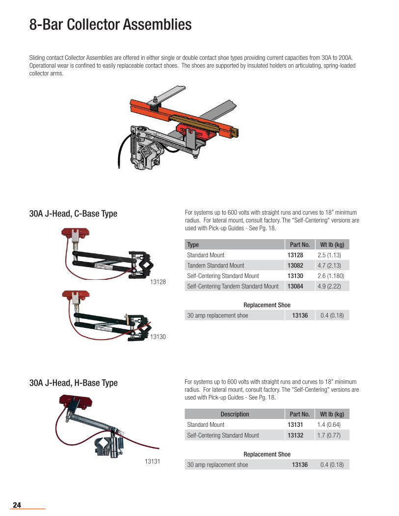
8-Bar Collector Assemblies
Sliding contact Collector Assemblies are offered in either single or double contact shoe types providing current capacities from 30A to 200A. Operational wear is confined to easily replaceable contact shoes. The shoes are supported by insulated holders on articulating, spring-loaded collector arms.
For systems up to 600 volts with straight runs and curves to 18” minimum radius. For lateral mount, consult factory. The "Self-Centering" versions are used with Pick-up Guides - See Pg. 18.
Type Part No. Wt lb (kg)
Standard Mount 13128 2.5 (1.13)
Tandem Standard Mount 13082 4.7 (2.13)
Self-Centering Standard Mount 13130 2.6 (1.180)
Self-Centering Tandem Standard Mount 13084 4.9 (2.22)
Replacement Shoe
30 amp replacement shoe 13136 0.4 (0.18)
Description Part No. Wt lb (kg)
Standard Mount 13131 1.4 (0.64)
Self-Centering Standard Mount 13132 1.7 (0.77)
Replacement Shoe
30 amp replacement shoe 13136 0.4 (0.18)
30A J-Head, C-Base Type
30A J-Head, H-Base Type For systems up to 600 volts with straight runs and curves to 18” minimum radius. For lateral mount, consult factory. The "Self-Centering" versions are used with Pick-up Guides - See Pg. 18.
13130
25
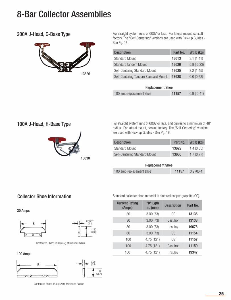
8-Bar Collector Assemblies
13626
13630
For straight system runs of 600V or less. For lateral mount, consult factory. The "Self-Centering" versions are used with Pick-up Guides - See Pg. 18.
Description Part No. Wt lb (kg)
Standard Mount 13613 3.1 (1.41)
Standard tandem Mount 13626 5.8 ( 6.23)
Self-Centering Standard Mount 13625 3.2 (1.45)
Self-Centering Tandem Standard Mount 13628 6.0 (0.72)
Replacement Shoe
100 amp replacement shoe 11157 0.9 ( 0.41)
Description Part No. Wt lb (kg)
Standard Mount 13629 1.4 (0.65)
Self-Centering Standard Mount 13630 1.7 (0.77)
Replacement Shoe
100 amp replacement shoe 11157 0.9 (0.41)
For straight system runs of 600V or less, and curves to a minimum of 48” radius. For lateral mount, consult factory. The "Self-Centering" versions are used with Pick-up Guides - See Pg. 18.
200A J-Head, C-Base Type
100A J-Head, H-Base Type
Collector Shoe InformationCurrent Rating
(Amps)"B" Lgthin. (mm)
Description Part No.
30 3.00 (73) CG 13136
30 3.00 (73) Cast Iron 13138
30 3.00 (73) Insuloy 19678
60 3.00 (73) CG 11154
100 4.75 (121) CG 11157
100 4.75 (121) Cast Iron 11159
100 4.75 (121) Insuloy 19347
Standard collector shoe material is sintered copper graphite (CG).
Contoured Shoe: 18.0 (457) Minimum Radius
B0.1875”
(4.8)
1.125(28.6)
30 Amps
100 Amps
Contoured Shoe: 48.0 (1219) Minimum Radius
4.75 (121)0.25 (6.4)
1.0(25.4)
B
26
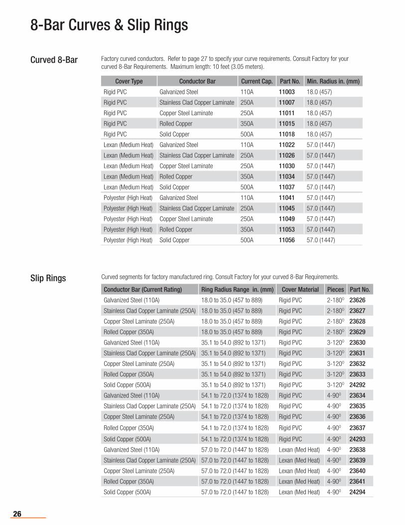
8-Bar Curves & Slip Rings
Curved 8-Bar Factory curved conductors. Refer to page 27 to specify your curve requirements. Consult Factory for your curved 8-Bar Requirements. Maximum length: 10 feet (3.05 meters).
Cover Type Conductor Bar Current Cap. Part No. Min. Radius in. (mm)
Rigid PVC Galvanized Steel 110A 11003 18.0 (457)
Rigid PVC Stainless Clad Copper Laminate 250A 11007 18.0 (457)
Rigid PVC Copper Steel Laminate 250A 11011 18.0 (457)
Rigid PVC Rolled Copper 350A 11015 18.0 (457)
Rigid PVC Solid Copper 500A 11018 18.0 (457)
Lexan (Medium Heat) Galvanized Steel 110A 11022 57.0 (1447)
Lexan (Medium Heat) Stainless Clad Copper Laminate 250A 11026 57.0 (1447)
Lexan (Medium Heat) Copper Steel Laminate 250A 11030 57.0 (1447)
Lexan (Medium Heat) Rolled Copper 350A 11034 57.0 (1447)
Lexan (Medium Heat) Solid Copper 500A 11037 57.0 (1447)
Polyester (High Heat) Galvanized Steel 110A 11041 57.0 (1447)
Polyester (High Heat) Stainless Clad Copper Laminate 250A 11045 57.0 (1447)
Polyester (High Heat) Copper Steel Laminate 250A 11049 57.0 (1447)
Polyester (High Heat) Rolled Copper 350A 11053 57.0 (1447)
Polyester (High Heat) Solid Copper 500A 11056 57.0 (1447)
Conductor Bar (Current Rating) Ring Radius Range in. (mm) Cover Material Pieces Part No.
Galvanized Steel (110A) 18.0 to 35.0 (457 to 889) Rigid PVC 2-180O 23626
Stainless Clad Copper Laminate (250A) 18.0 to 35.0 (457 to 889) Rigid PVC 2-180O 23627
Copper Steel Laminate (250A) 18.0 to 35.0 (457 to 889) Rigid PVC 2-180O 23628
Rolled Copper (350A) 18.0 to 35.0 (457 to 889) Rigid PVC 2-180O 23629
Galvanized Steel (110A) 35.1 to 54.0 (892 to 1371) Rigid PVC 3-120O 23630
Stainless Clad Copper Laminate (250A) 35.1 to 54.0 (892 to 1371) Rigid PVC 3-120O 23631
Copper Steel Laminate (250A) 35.1 to 54.0 (892 to 1371) Rigid PVC 3-120O 23632
Rolled Copper (350A) 35.1 to 54.0 (892 to 1371) Rigid PVC 3-120O 23633
Solid Copper (500A) 35.1 to 54.0 (892 to 1371) Rigid PVC 3-120O 24292
Galvanized Steel (110A) 54.1 to 72.0 (1374 to 1828) Rigid PVC 4-90O 23634
Stainless Clad Copper Laminate (250A) 54.1 to 72.0 (1374 to 1828) Rigid PVC 4-90O 23635
Copper Steel Laminate (250A) 54.1 to 72.0 (1374 to 1828) Rigid PVC 4-90O 23636
Rolled Copper (350A) 54.1 to 72.0 (1374 to 1828) Rigid PVC 4-90O 23637
Solid Copper (500A) 54.1 to 72.0 (1374 to 1828) Rigid PVC 4-90O 24293
Galvanized Steel (110A) 57.0 to 72.0 (1447 to 1828) Lexan (Med Heat) 4-90O 23638
Stainless Clad Copper Laminate (250A) 57.0 to 72.0 (1447 to 1828) Lexan (Med Heat) 4-90O 23639
Copper Steel Laminate (250A) 57.0 to 72.0 (1447 to 1828) Lexan (Med Heat) 4-90O 23640
Rolled Copper (350A) 57.0 to 72.0 (1447 to 1828) Lexan (Med Heat) 4-90O 23641
Solid Copper (500A) 57.0 to 72.0 (1447 to 1828) Lexan (Med Heat) 4-90O 24294
Curved segments for factory manufactured ring. Consult Factory for your curved 8-Bar Requirements.Slip Rings
27
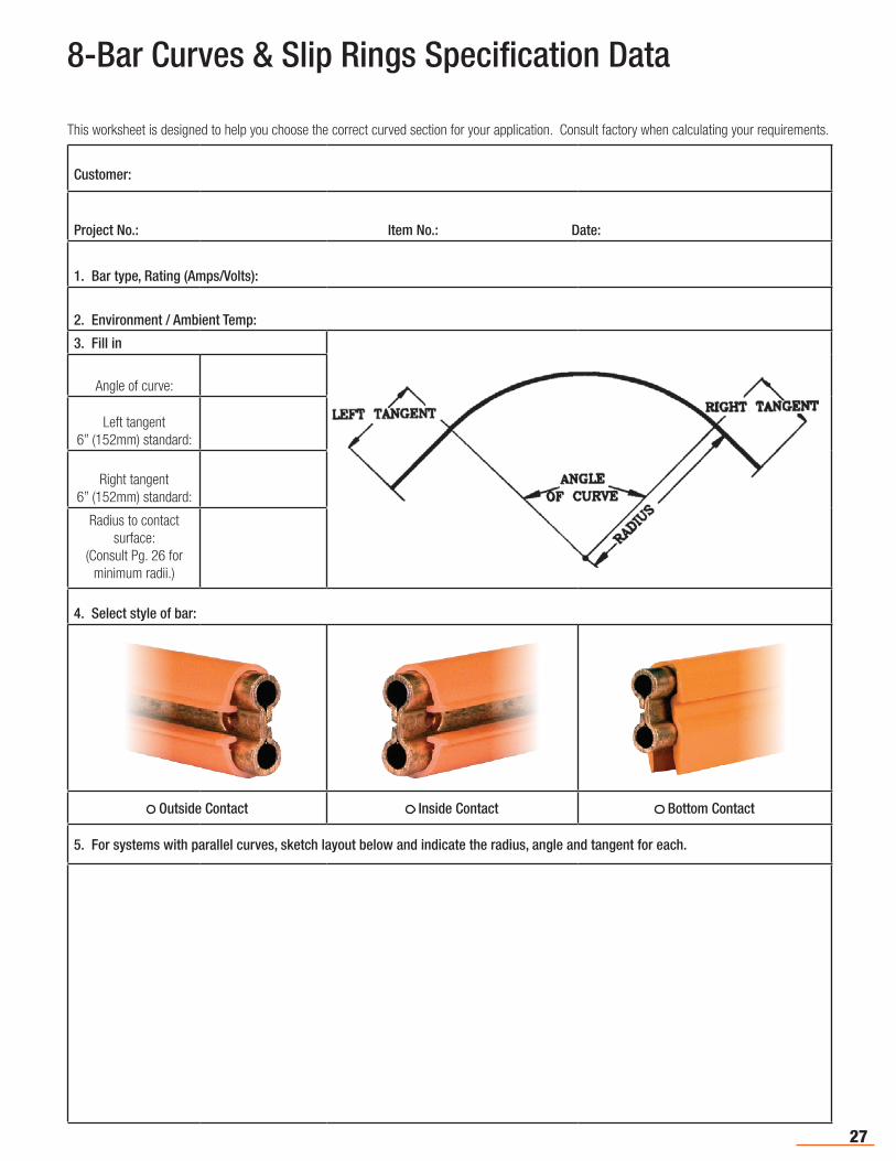
8-Bar Curves & Slip Rings Specification Data
This worksheet is designed to help you choose the correct curved section for your application. Consult factory when calculating your requirements.
Customer:
Project No.: Item No.: Date:
1. Bar type, Rating (Amps/Volts):
2. Environment / Ambient Temp:
3. Fill in
Angle of curve:
Left tangent 6” (152mm) standard:
Right tangent 6” (152mm) standard:
Radius to contact surface:
(Consult Pg. 26 for minimum radii.)
4. Select style of bar:
Outside Contact Inside Contact Bottom Contact
5. For systems with parallel curves, sketch layout below and indicate the radius, angle and tangent for each.
28
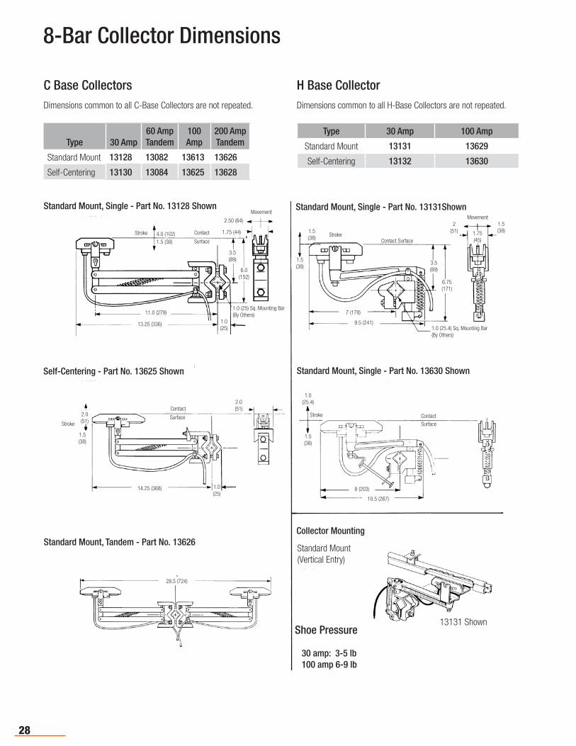
8-Bar Collector Dimensions
Type 30 Amp60 Amp Tandem
100 Amp
200 AmpTandem
Standard Mount 13128 13082 13613 13626
Self-Centering 13130 13084 13625 13628
C Base Collectors H Base Collector
Type 30 Amp 100 Amp
Standard Mount 13131 13629
Self-Centering 13132 13630
Dimensions common to all C-Base Collectors are not repeated. Dimensions common to all H-Base Collectors are not repeated.
1.5 (38)
3.5(89)
2.50 (64)
1.75 (44)
1.0 (25) Sq. Mounting Bar (By Others)
1.0(25)
13.25 (336)
11.0 (279)
6.0 (152)
1.5(38)
14.25 (368)
2.0 (51)
1.0(25)
28.5 (724)
1.0(25.4)
1.5(38)
8 (203)
10.5 (267)
9.5 (241)
7 (178)
6.75 (171)
3.5(89)
1.5 (38)
1.5 (38)
2(51)
1.5(38)1.75
(45)
1.0 (25.4) Sq. Mounting Bar (By Others)
Standard Mount, Single - Part No. 13128 Shown
Self-Centering - Part No. 13625 Shown
Standard Mount, Tandem - Part No. 13626
Standard Mount, Single - Part No. 13131Shown
Collector Mounting
Shoe Pressure
30 amp: 3-5 lb 100 amp 6-9 lb
4.0 (102)
13131 Shown
Standard Mount(Vertical Entry)
Contact
Movement
Contact SurfaceStroke
Movement
Stroke
Stroke
Surface
ContactStrokeSurface Contact
Surface
Standard Mount, Single - Part No. 13630 Shown
2.0 (51)
29
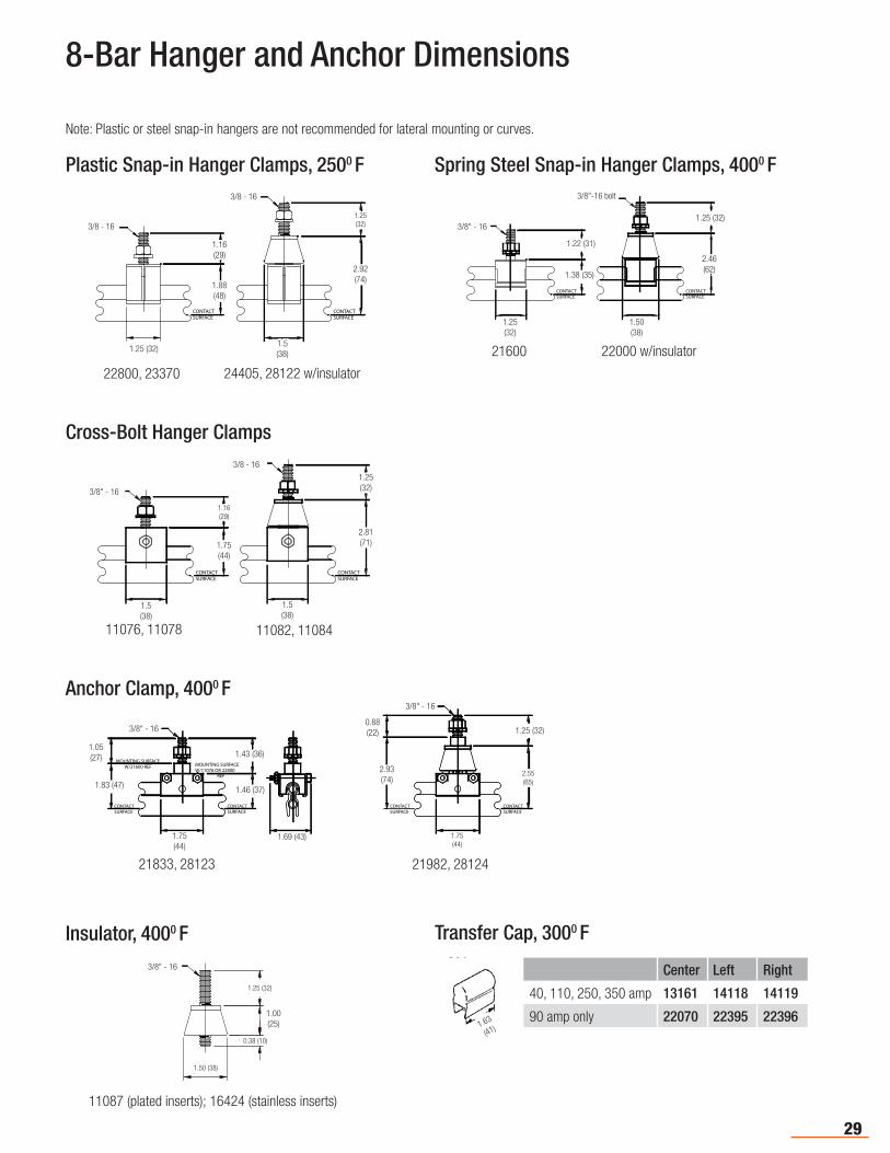
8-Bar Hanger and Anchor Dimensions
Note: Plastic or steel snap-in hangers are not recommended for lateral mounting or curves.
Plastic Snap-in Hanger Clamps, 2500 F Spring Steel Snap-in Hanger Clamps, 4000 F
1.16[29mm]
1.88[48mm]
CONTACTSURFACE
1.25[32mm]
2.92[74mm]
SURFACECONTACT
1.25[32mm]
1.50[38mm]
3/8-16
3/8-16
1.16 (29)
1.88 (48)
1.25(32)
1.25 (32)
2.92 (74)
1.5 (38)
3/8 - 16
3/8 - 16
22800, 23370 24405, 28122 w/insulator
1.25[32mm]
2.46[62mm]
SURFACECONTACT
1.25[32mm]
1.50[38mm]
3/8-16
3/8-16
1.38[35mm]
1.22[31mm]
CONTACTSURFACE
1.25 (32)
1.22 (31)
1.38 (35)
1.25 (32)
2.46(62)
3/8"-16 bolt
3/8" - 16
21600 22000 w/insulator
1.50 (38)
1.63
(41)
3/8-16
1.25[32mm]
1.00[25mm]
0.38 [10mm]
1.50[38mm]1.50 (38)
1.00 (25)
0.38 (10)
1.25 (32)
3/8" - 16
11087 (plated inserts); 16424 (stainless inserts)
Insulator, 4000 F Transfer Cap, 3000 F
Center Left Right
40, 110, 250, 350 amp 13161 14118 14119
90 amp only 22070 22395 22396
Cross-Bolt Hanger Clamps
1.50[38mm]
2.81[71mm]
SURFACECONTACT
1.50[38mm]
3/8-16
3/8-16
1.75[44mm]
1.16[29mm]
CONTACTSURFACE
1.25[32mm]
1.16 (29)
1.75 (44)
1.5 (38)
2.81(71)
1.25 (32)3/8" - 16
3/8 - 16
11076, 11078 11082, 11084
1.5 (38)
Anchor Clamp, 4000 F
1.75[44mm]
2.55[65mm]
SURFACECONTACT
1.75[44mm]
3/8-16
3/8-16
1.46[37mm]
1.43 [36mm]
CONTACTSURFACE
1.25[32mm]
1.05[27mm]
1.83[47mm]
CONTACTSURFACE
MOUNTING SURFACEW/21600 REF MOUNTING SURFACE
W/11076 OR 22800REF
1.69[43mm]
2.93[74mm]
CONTACTSURFACE
0.88[22mm]0.88 (22)
2.55 (65)
2.93 (74)
1.25 (32)
1.05(27)
1.83 (47)
1.75(44)
1.43 (36)
3/8" - 16
3/8" - 16
21833, 28123 21982, 28124
1.69 (43)
1.46 (37)
1.75(44)
30
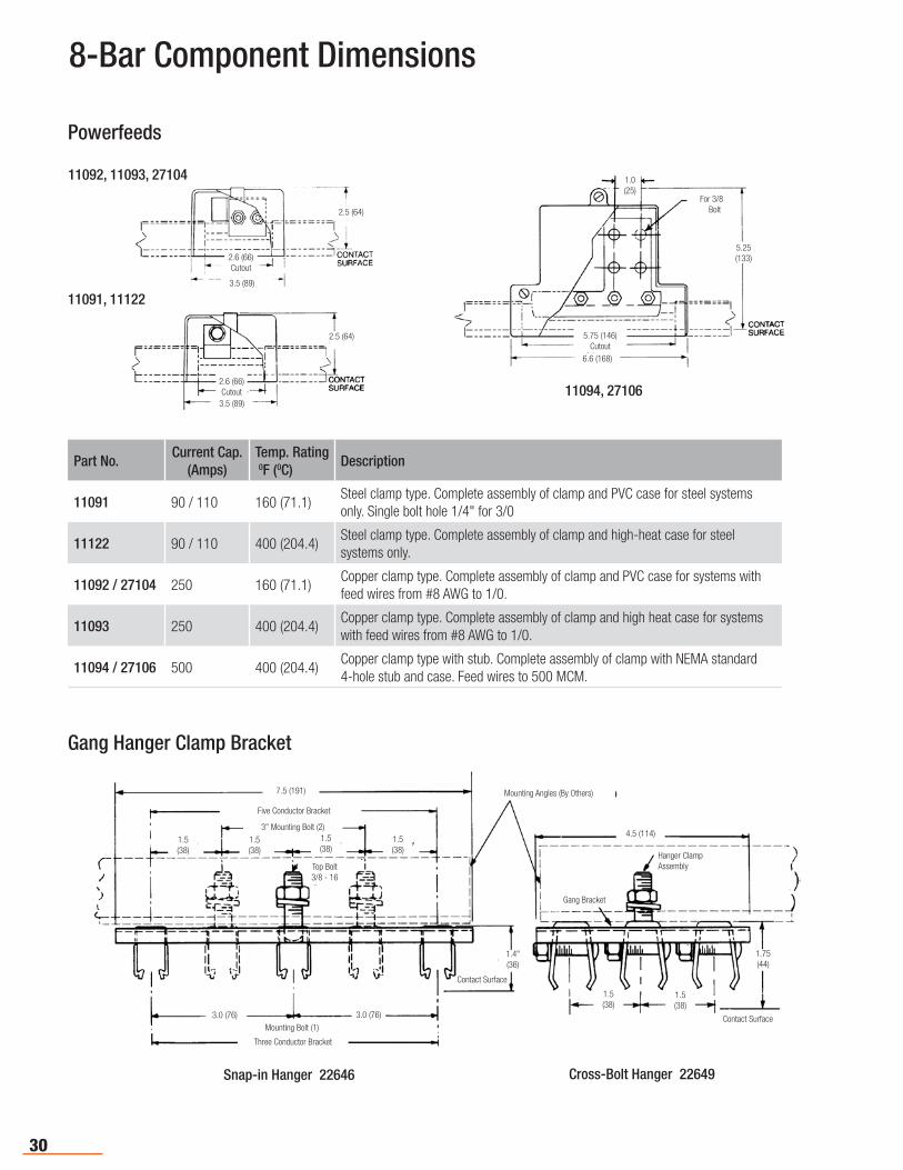
Powerfeeds
8-Bar Component Dimensions
2.5 (64)
3.5 (89)
2.6 (66)Cutout
3.5 (89)
2.5 (64)
1.0(25)
5.25(133)
6.6 (168)
For 3/8 Bolt
2.6 (66)Cutout
5.75 (146)Cutout
11092, 11093, 27104
11091, 11122
Part No.Current Cap.
(Amps)Temp. Rating 0F (0C)
Description
11091 90 / 110 160 (71.1)Steel clamp type. Complete assembly of clamp and PVC case for steel systems only. Single bolt hole 1/4" for 3/0
11122 90 / 110 400 (204.4)Steel clamp type. Complete assembly of clamp and high-heat case for steel systems only.
11092 / 27104 250 160 (71.1)Copper clamp type. Complete assembly of clamp and PVC case for systems with feed wires from #8 AWG to 1/0.
11093 250 400 (204.4)Copper clamp type. Complete assembly of clamp and high heat case for systems with feed wires from #8 AWG to 1/0.
11094 / 27106 500 400 (204.4)Copper clamp type with stub. Complete assembly of clamp with NEMA standard 4-hole stub and case. Feed wires to 500 MCM.
11094, 27106
Gang Hanger Clamp Bracket
1.5(38)
1.5(38)
1.5(38)
1.5(38)
7.5 (191)
1.4"(36)
3.0 (76) 3.0 (76)
1.5(38)
1.5(38)
4.5 (114)
1.75(44)
Five Conductor Bracket
Top Bolt3/8 - 16
Contact Surface
Mounting Angles (By Others)
Three Conductor Bracket
Mounting Bolt (1)
3" Mounting Bolt (2)
Gang Bracket
Contact Surface
Hanger ClampAssembly
Snap-in Hanger 22646 Cross-Bolt Hanger 22649
31
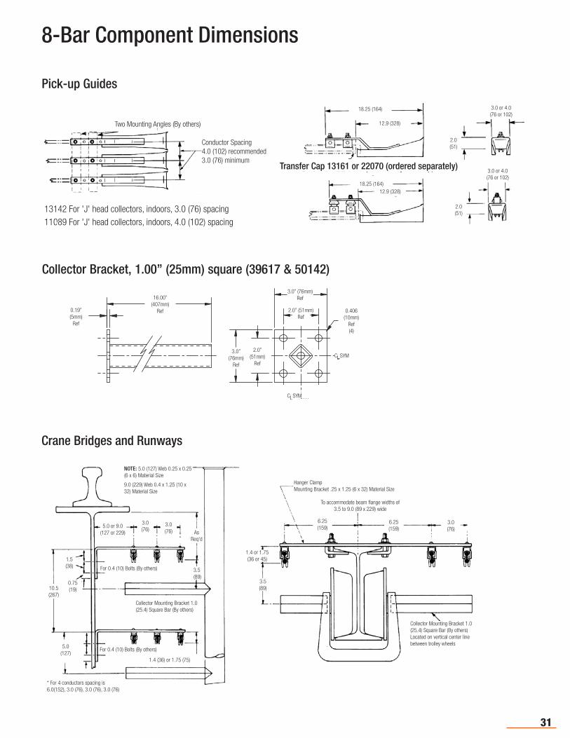
Pick-up Guides
Crane Bridges and Runways
8-Bar Component Dimensions
5.0 or 9.0(127 or 229)
3.0(76)
3.0(76)
3.5(89)
10.5(267)
5.0(127)
1.5(38)
0.75(19)
* For 4 conductors spacing is 6.0(152), 3.0 (76), 3.0 (76), 3.0 (76)
For 0.4 (10) Bolts (By others)
For 0.4 (10) Bolts (By others)
1.4 (36) or 1.75 (75)
Collector Mounting Bracket 1.0 (25.4) Square Bar (By others)
NOTE: 5.0 (127) Web 0.25 x 0.25 (6 x 6) Material Size
9.0 (229) Web 0.4 x 1.25 (10 x 32) Material Size
3.0(76)
3.5(89)
1.4 or 1.75(36 or 45)
6.25(159)
6.25(159)
Hanger ClampMounting Bracket .25 x 1.25 (6 x 32) Material Size
Collector Mounting Bracket 1.0 (25.4) Square Bar (By others)Located on vertical center line between trolley wheels
To accommodate beam flange widths of 3.5 to 9.0 (89 x 229) wide
AsReq'd
18.25 (164)
12.9 (328)
12.9 (328)18.25 (164)
3.0 or 4.0(76 or 102)
3.0 or 4.0(76 or 102)
Conductor Spacing4.0 (102) recommended3.0 (76) minimum
Two Mounting Angles (By others)
Transfer Cap 13161 or 22070 (ordered separately)
2.0(51)
2.0(51)13142 For 'J' head collectors, indoors, 3.0 (76) spacing
11089 For 'J' head collectors, indoors, 4.0 (102) spacing
Collector Bracket, 1.00” (25mm) square (39617 & 50142)
16.00” (407mm)
Ref0.19” (5mm)
Ref
2.0” (51mm)
Ref
3.0” (76mm)
Ref
C SYML
C SYML
3.0” (76mm)Ref
2.0” (51mm)Ref
0.406(10mm)
Ref(4)
32
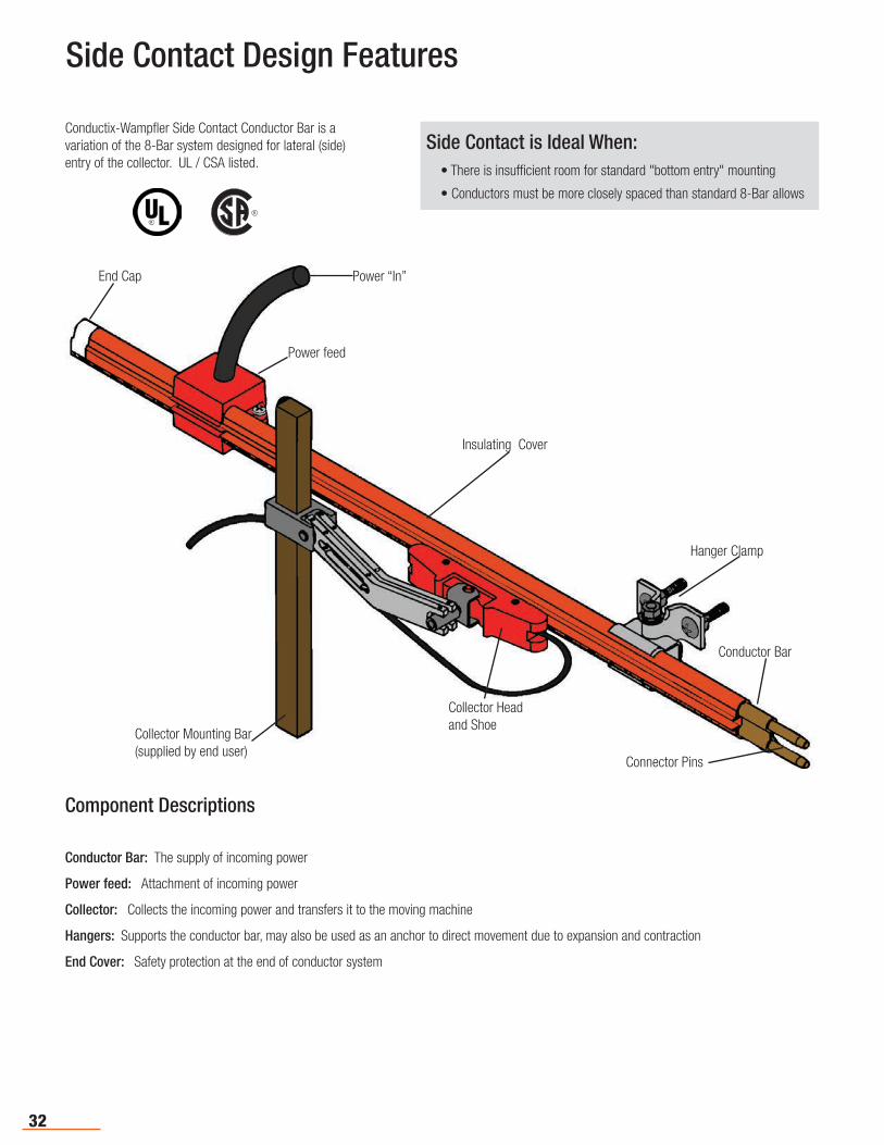
Side Contact Design Features
End Cap
Power feed
Power “In”
Collector Mounting Bar(supplied by end user)
Collector Head and Shoe
Connector Pins
Conductor Bar
Hanger Clamp
Insulating Cover
Component Descriptions
Conductor Bar: The supply of incoming power
Power feed: Attachment of incoming power
Collector: Collects the incoming power and transfers it to the moving machine
Hangers: Supports the conductor bar, may also be used as an anchor to direct movement due to expansion and contraction
End Cover: Safety protection at the end of conductor system
Conductix-Wampfler Side Contact Conductor Bar is a variation of the 8-Bar system designed for lateral (side) entry of the collector. UL / CSA listed.
R
Side Contact is Ideal When: • There is insufficient room for standard "bottom entry" mounting
• Conductors must be more closely spaced than standard 8-Bar allows
33
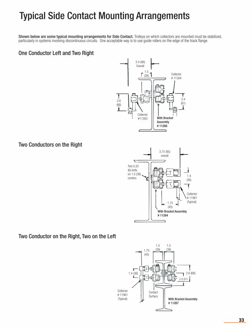
Typical Side Contact Mounting Arrangements
Shown below are some typical mounting arrangements for Side Contact. Trolleys on which collectors are mounted must be stabilized, particularly in systems involving discontinuous circuits. One acceptable way is to use guide rollers on the edge of the track flange.
One Conductor Left and Two Right
Two Conductor on the Right, Two on the Left
Two Conductors on the Right
1.4 (36)
1.75(45)
1.5(38)
1.5(38)
2.0 (51)
2.6 (66)
With Bracket Assembly# 11267
Collector# 11961(Typical)
Contact Surface
3.75 (95)overall
1.4(36)
With Bracket Assembly# 11264
Two 0.25 (6) bolts on 1.5 (38) centers
Collector# 11961(Typical)1.75
(45)
2.6(66)
1.5(38)
3.4 (86)Overall
2.4(61)
Collector# 11304
Collector#11303 With Bracket
Assembly # 11266
34
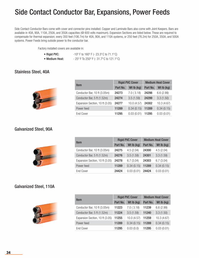
ItemRigid PVC Cover Medium Heat Cover
Part No. Wt lb (kg) Part No. Wt lb (kg)
Conductor Bar, 10 ft (3.05m) 24273 7.0 ( 3.18) 24298 6.6 (2.99)
Conductor Bar, 5 ft (1.52m) 24274 3.5 (1.59) 24299 3.3 (1.50)
Expansion Section, 10 ft (3.05) 24277 10.0 (4.57) 24302 10.3 (4.67)
Power feed 11289 0.34 (0.15) 11289 0.34 (0.15)
End Cover 11295 0.03 (0.01) 11295 0.03 (0.01)
Stainless Steel, 40A
Galvanized Steel, 90A
Side Contact Conductor Bars come with cover and connector pins installed. Copper and Laminate Bars also come with Joint Keepers. Bars are available in 40A, 90A, 110A, 250A, and 350A capacities (@ 600 volts maximum). Expansion Sections are listed below. These are required to compensate for thermal expansion; every 350 feet (106.7m) for 40A, 90A, and 110A systems, or 250 feet (76.2m) for 250A, 350A, and 500A systems. Power Feeds bring outside power to the conductor bar.
Factory installed covers are available in:
• Rigid PVC: -10O F to 160O F (- 23.30 C to 71.10 C)• Medium Heat: - 25O F To 250O F (- 31.70 C to 121.10 C)
Galvanized Steel, 110A
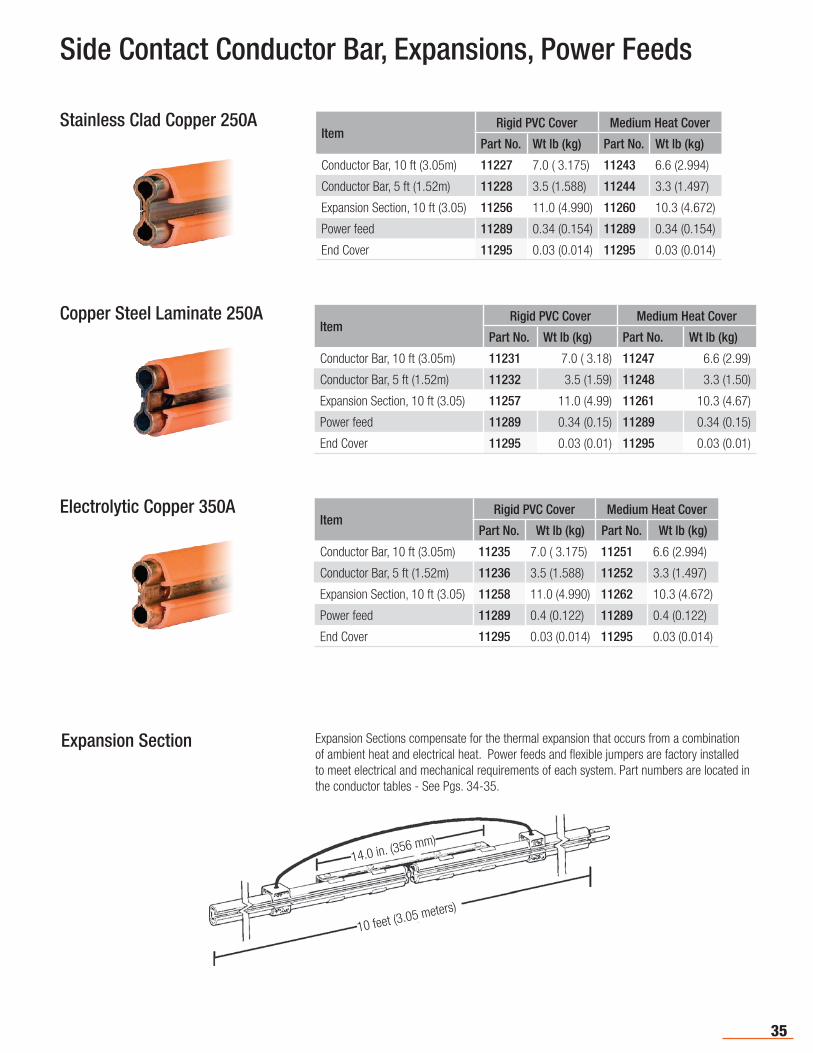
Side Contact Conductor Bar, Expansions, Power Feeds
ItemRigid PVC Cover Medium Heat Cover
Part No. Wt lb (kg) Part No. Wt lb (kg)
Conductor Bar, 10 ft (3.05m) 24275 4.5 (2.04) 24300 4.5 (2.04)
Conductor Bar, 5 ft (1.52m) 24276 3.5 (1.59) 24301 3.3 (1.59)
Expansion Section, 10 ft (3.05) 24278 6.7 (3.04) 24303 6.7 (3.04)
Power feed 11289 0.34 (0.15) 11289 0.34 (0.15)
End Cover 24424 0.03 (0.01) 24424 0.03 (0.01)
ItemRigid PVC Cover Medium Heat Cover
Part No. Wt lb (kg) Part No. Wt lb (kg)
Conductor Bar, 10 ft (3.05m) 11223 7.0 ( 3.18) 11239 6.6 (2.99)
Conductor Bar, 5 ft (1.52m) 11224 3.5 (1.59) 11240 3.3 (1.50)
Expansion Section, 10 ft (3.05) 11255 10.0 (4.57) 11259 10.3 (4.67)
Power feed 11289 0.34 (0.15) 11289 0.34 (0.15)
End Cover 11295 0.03 (0.0) 11295 0.03 (0.01)
35
Stainless Clad Copper 250A
Copper Steel Laminate 250A
Electrolytic Copper 350A
Expansion Section Expansion Sections compensate for the thermal expansion that occurs from a combination of ambient heat and electrical heat. Power feeds and flexible jumpers are factory installed to meet electrical and mechanical requirements of each system. Part numbers are located in the conductor tables - See Pgs. 34-35.
Side Contact Conductor Bar, Expansions, Power Feeds
10 feet (3.05 meters)
14.0 in. (356 mm)
ItemRigid PVC Cover Medium Heat Cover
Part No. Wt lb (kg) Part No. Wt lb (kg)
Conductor Bar, 10 ft (3.05m) 11227 7.0 ( 3.175) 11243 6.6 (2.994)
Conductor Bar, 5 ft (1.52m) 11228 3.5 (1.588) 11244 3.3 (1.497)
Expansion Section, 10 ft (3.05) 11256 11.0 (4.990) 11260 10.3 (4.672)
Power feed 11289 0.34 (0.154) 11289 0.34 (0.154)
End Cover 11295 0.03 (0.014) 11295 0.03 (0.014)
ItemRigid PVC Cover Medium Heat Cover
Part No. Wt lb (kg) Part No. Wt lb (kg)
Conductor Bar, 10 ft (3.05m) 11231 7.0 ( 3.18) 11247 6.6 (2.99)
Conductor Bar, 5 ft (1.52m) 11232 3.5 (1.59) 11248 3.3 (1.50)
Expansion Section, 10 ft (3.05) 11257 11.0 (4.99) 11261 10.3 (4.67)
Power feed 11289 0.34 (0.15) 11289 0.34 (0.15)
End Cover 11295 0.03 (0.01) 11295 0.03 (0.01)
ItemRigid PVC Cover Medium Heat Cover
Part No. Wt lb (kg) Part No. Wt lb (kg)
Conductor Bar, 10 ft (3.05m) 11235 7.0 ( 3.175) 11251 6.6 (2.994)
Conductor Bar, 5 ft (1.52m) 11236 3.5 (1.588) 11252 3.3 (1.497)
Expansion Section, 10 ft (3.05) 11258 11.0 (4.990) 11262 10.3 (4.672)
Power feed 11289 0.4 (0.122) 11289 0.4 (0.122)
End Cover 11295 0.03 (0.014) 11295 0.03 (0.014)
36
Side Contact Connectors and Covers
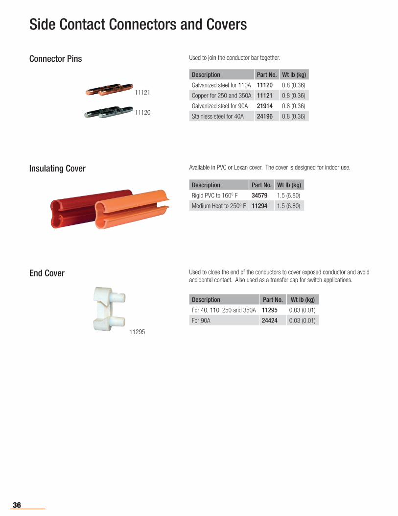
Connector Pins Used to join the conductor bar together.
Description Part No. Wt lb (kg)
Galvanized steel for 110A 11120 0.8 (0.36)
Copper for 250 and 350A 11121 0.8 (0.36)
Galvanized steel for 90A 21914 0.8 (0.36)
Stainless steel for 40A 24196 0.8 (0.36)
Insulating Cover Available in PVC or Lexan cover. The cover is designed for indoor use.
Description Part No. Wt lb (kg)
Rigid PVC to 160O F 34579 1.5 (6.80)
Medium Heat to 250O F 11294 1.5 (6.80)
End Cover Used to close the end of the conductors to cover exposed conductor and avoid accidental contact. Also used as a transfer cap for switch applications.
Description Part No. Wt lb (kg)
For 40, 110, 250 and 350A 11295 0.03 (0.01)
For 90A 24424 0.03 (0.01)
11121
11120
11295
37
Side Contact Power Feed & Pick-up Guide
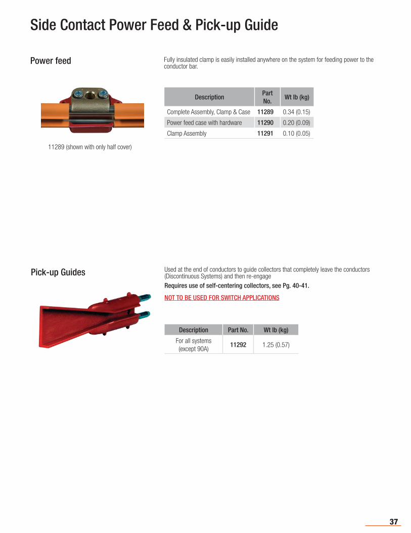
Power feed Fully insulated clamp is easily installed anywhere on the system for feeding power to the conductor bar.
DescriptionPart No.
Wt lb (kg)
Complete Assembly, Clamp & Case 11289 0.34 (0.15)
Power feed case with hardware 11290 0.20 (0.09)
Clamp Assembly 11291 0.10 (0.05)
Pick-up Guides Used at the end of conductors to guide collectors that completely leave the conductors (Discontinuous Systems) and then re-engage Requires use of self-centering collectors, see Pg. 40-41.
NOT TO BE USED FOR SWITCH APPLICATIONS
Description Part No. Wt lb (kg)
For all systems(except 90A)
11292 1.25 (0.57)
11289 (shown with only half cover)
38
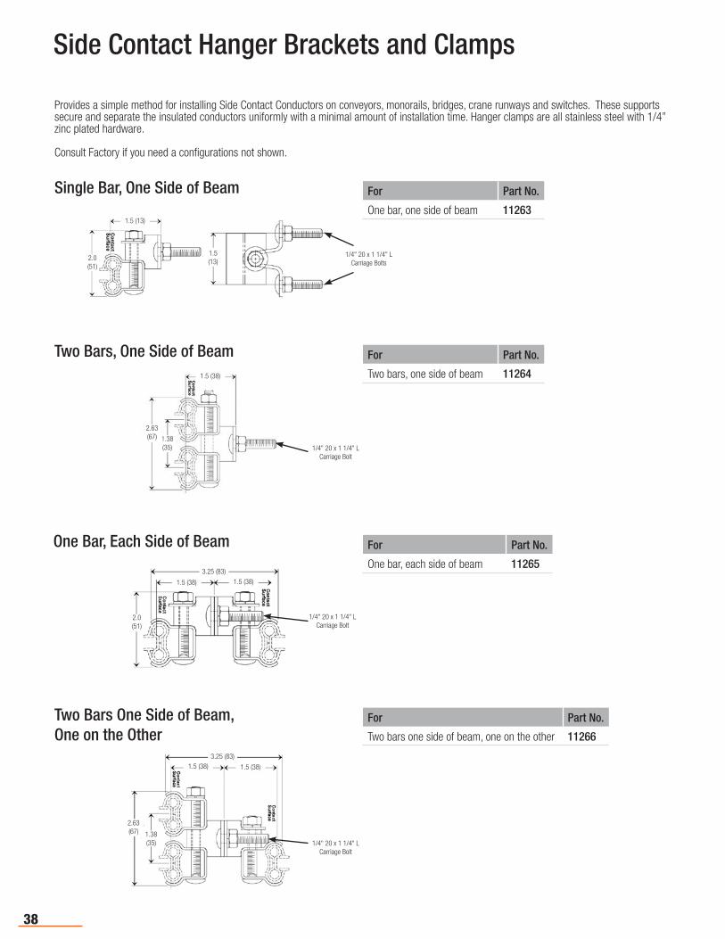
Side Contact Hanger Brackets and Clamps
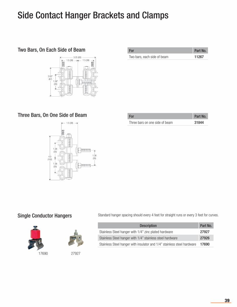
Two Bars, One Side of Beam
Provides a simple method for installing Side Contact Conductors on conveyors, monorails, bridges, crane runways and switches. These supports secure and separate the insulated conductors uniformly with a minimal amount of installation time. Hanger clamps are all stainless steel with 1/4” zinc plated hardware.
Consult Factory if you need a configurations not shown.
For Part No.
One bar, one side of beam 11263
Single Bar, One Side of Beam
For Part No.
Two bars, one side of beam 11264
For Part No.
One bar, each side of beam 11265
One Bar, Each Side of Beam
For Part No.
Two bars one side of beam, one on the other 11266
Two Bars One Side of Beam, One on the Other
3.25 (83)1.5 (38) 1.5 (38)
2.63 (67) 1.38
(35) 1/4" 20 x 1 1/4" LCarriage Bolt
3.25 (83)
1.5 (38)1.5 (38)
2.0(51)
1/4" 20 x 1 1/4" LCarriage Bolt
1.5 (38)
1.38 (35)
2.63 (67)
1/4" 20 x 1 1/4" LCarriage Bolt
2.0(51)
1.5(13)
1.5 (13)
1/4" 20 x 1 1/4" LCarriage Bolts
39
Single Conductor Hangers Standard hanger spacing should every 4 feet for straight runs or every 3 feet for curves.
Description Part No.
Stainless Steel hanger with 1/4” zinc plated hardware 27927
Stainless Steel hanger with 1/4” stainless steel hardware 27926
Stainless Steel hanger with insulator and 1/4” stainless steel hardware 17690
1.5 (38)
1.38 (35)
1.38 (35)
1.38 (35)
4.0 (102)
1.38" (35)
2.63" (67)
3.25 (83)1.5 (38) 1.5 (38)
17690 27927
For Part No.
Two bars, each side of beam 11267
For Part No.
Three bars on one side of beam 31844
Two Bars, On Each Side of Beam
Three Bars, On One Side of Beam
Side Contact Hanger Brackets and Clamps

40
M-Head, H-Base Type, 40A
Description Part No.
Standard Collector, for continuous systems 12304
Same as 12304, except a counter weight is added for lateral mount
12306
12304
This rugged collector provides a long stroke for continuous systems where clearance is not restricted. Standard pigtail length: 15" (381 mm)
Side Contact Collectors
M-Head, L-Base Type, 40A
Description Part No.
Standard Collector, for continuous systems 11961
Self Centering Collector, for discontinuous systems that are equipped with pickup guide 11292
1229511961
12295
M-Head, L-Base Type, 80A
Description Part No.
Standard Collector, for continuous systems 11517
Self Centering Collector, for discontinuous systems that are equipped with pickup guide 11292
1151811517
For conveyor, monorail systems, and crane bridges. Operates through curves at a minimum radii of 9.0 (228).Standard pigtail length: 15" (381 mm)
For conveyor, monorail systems, and crane bridges. Operates through curves at a minimum radii of 9.0 (228). Includes an additional pigtail for extra current capacity. Standard pigtail length: 15" (381 mm)
Side Contact Collectors are available in numerous configurations to match the application. Note that collectors should not be used as power switching devices. The resultant arcing may cause rapid deterioration of both contact shoes and conductor bars. Ampere capacity of conductor bars, power feeds, jumpers etc., should be greater than or equal to that off the system. Consult factory for systems using tandem mounted collectors and special requirements. For mechanically discontinuous systems, only collectors designated as "self-centering" should be used.
Contact shoe pressure: Between 4 and 6 pounds (1.81 kg to 2.72 kg) for all collector styles.
41
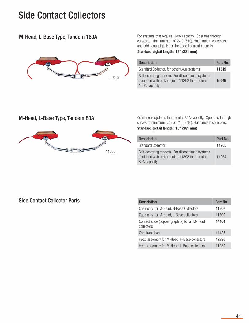
Side Contact Collectors
M-Head, L-Base Type, Tandem 160A
Description Part No.
Standard Collector, for continuous systems 11519
Self-centering tandem. For discontinued systems equipped with pickup guide 11292 that require 160A capacity.
1504611519
For systems that require 160A capacity. Operates through curves to minimum radii of 24.0 (610). Has tandem collectors and additional pigtails for the added current capacity. Standard pigtail length: 15" (381 mm)
M-Head, L-Base Type, Tandem 80A
Description Part No.
Standard Collector 11955
Self-centering tandem. For discontinued systems equipped with pickup guide 11292 that require 80A capacity.
1195411955
Continuous systems that require 80A capacity. Operates through curves to minimum radii of 24.0 (610). Has tandem collectors. Standard pigtail length: 15" (381 mm)
Description Part No.
Case only, for M-Head, H-Base Collectors 11307
Case only, for M-Head, L-Base collectors 11300
Contact shoe (copper graphite) for all M-Head collectors
14104
Cast iron shoe 14135
Head assembly for M-Head, H-Base collectors 12296
Head assembly for M-Head, L-Base collectors 11930
Side Contact Collector Parts
42
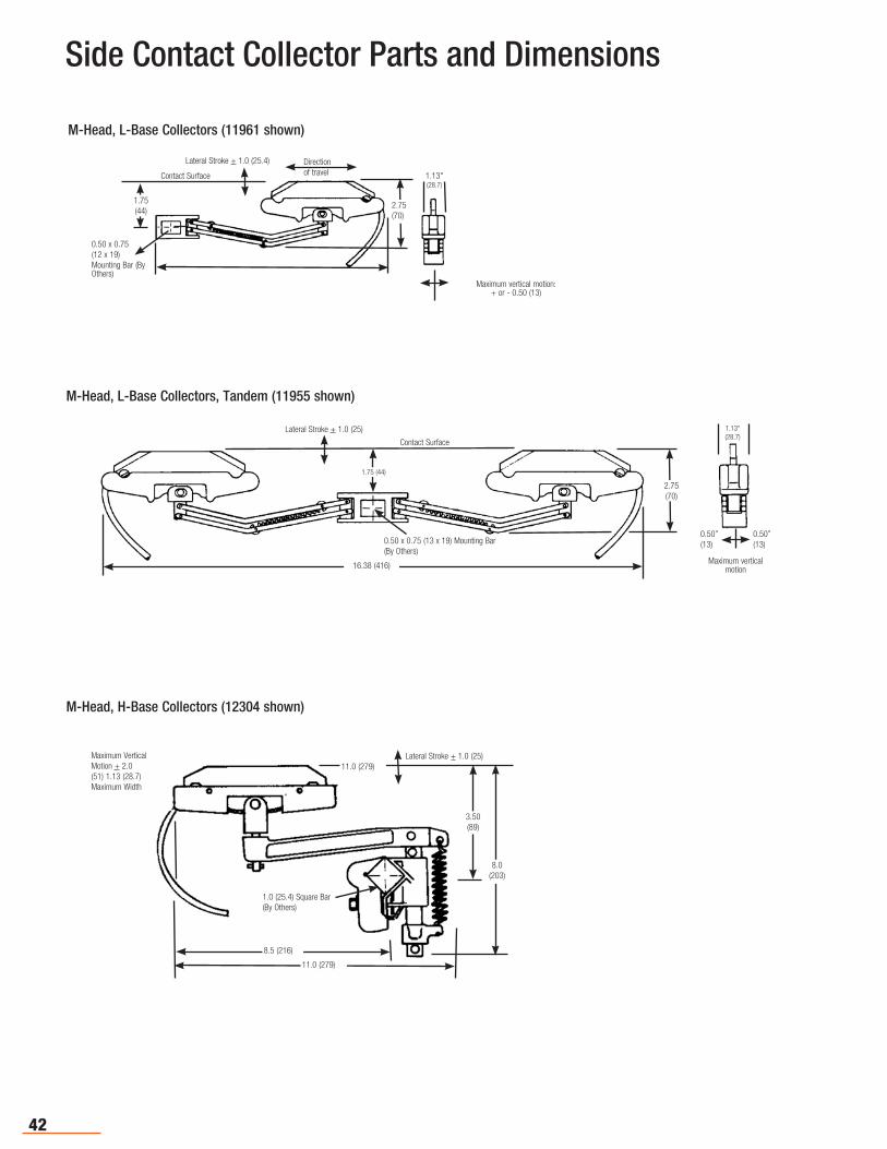
Side Contact Collector Parts and Dimensions
M-Head, L-Base Collectors (11961 shown)
Direction of travel
Lateral Stroke + 1.0 (25.4)
Contact Surface
0.50 x 0.75 (12 x 19)Mounting Bar (By Others)
1.13"(28.7)
Maximum vertical motion:+ or - 0.50 (13)
1.75(44)
2.75(70)
M-Head, L-Base Collectors, Tandem (11955 shown)
0.50”(13)
Contact Surface
1.75 (44)
0.50 x 0.75 (13 x 19) Mounting Bar (By Others)
16.38 (416)
2.75(70)
1.13"(28.7)
Maximum vertical motion
0.50”(13)
Lateral Stroke + 1.0 (25)
M-Head, H-Base Collectors (12304 shown)
Maximum Vertical Motion + 2.0 (51) 1.13 (28.7) Maximum Width
Lateral Stroke + 1.0 (25)
3.50(89)
8.0(203)
8.5 (216)
1.0 (25.4) Square Bar (By Others)
11.0 (279)
11.0 (279)
43
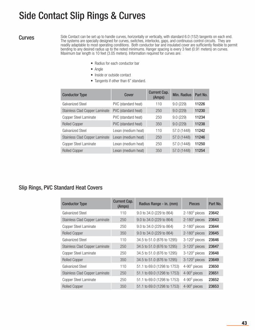
Side Contact Slip Rings & Curves
Slip Rings, PVC Standard Heat Covers
Curves
Conductor TypeCurrent Cap.
(Amps)Radius Range - in. (mm) Pieces Part No.
Galvanized Steel 110 9.0 to 34.0 (229 to 864) 2-180O pieces 23642
Stainless Clad Copper Laminate 250 9.0 to 34.0 (229 to 864) 2-180O pieces 23643
Copper Steel Laminate 250 9.0 to 34.0 (229 to 864) 2-180O pieces 23644
Rolled Copper 350 9.0 to 34.0 (229 to 864) 2-180O pieces 23645
Galvanized Steel 110 34.5 to 51.0 (876 to 1295) 3-120O pieces 23646
Stainless Clad Copper Laminate 250 34.5 to 51.0 (876 to 1295) 3-120O pieces 23647
Copper Steel Laminate 250 34.5 to 51.0 (876 to 1295) 3-120O pieces 23648
Rolled Copper 350 34.5 to 51.0 (876 to 1295) 3-120O pieces 23649
Galvanized Steel 110 51.1 to 69.0 (1298 to 1753) 4-90O pieces 23650
Stainless Clad Copper Laminate 250 51.1 to 69.0 (1298 to 1753) 4-90O pieces 23651
Copper Steel Laminate 250 51.1 to 69.0 (1298 to 1753) 4-90O pieces 23652
Rolled Copper 350 51.1 to 69.0 (1298 to 1753) 4-90O pieces 23653
Side Contact can be set up to handle curves, horizontally or vertically, with standard 6.0 (152) tangents on each end. The systems are specially designed for curves, switches, interlocks, gaps, and continuous control circuits. They are readily adaptable to most operating conditions. Both conductor bar and insulated cover are sufficiently flexible to permit bending to any desired radius up to the noted minimums. Hanger spacing is every 3 feet (0.91 meters) on curves. Maximum bar length is 10 feet (3.05 meters). Information required for curves are:
• Radius for each conductor bar• Angle• Inside or outside contact• Tangents if other than 6” standard.
Conductor Type CoverCurrent Cap.
(Amps)Min. Radius Part No.
Galvanized Steel PVC (standard heat) 110 9.0 (229) 11226
Stainless Clad Copper Laminate PVC (standard heat) 250 9.0 (229) 11230
Copper Steel Laminate PVC (standard heat) 250 9.0 (229) 11234
Rolled Copper PVC (standard heat) 350 9.0 (229) 11238
Galvanized Steel Lexan (medium heat) 110 57.0 (1448) 11242
Stainless Clad Copper Laminate Lexan (medium heat) 250 57.0 (1448) 11246
Copper Steel Laminate Lexan (medium heat) 250 57.0 (1448) 11250
Rolled Copper Lexan (medium heat) 350 57.0 (1448) 11254
44
Cluster Bar Features
Automate your work with our advanced “Quick Quote” software - See Pg. 5.
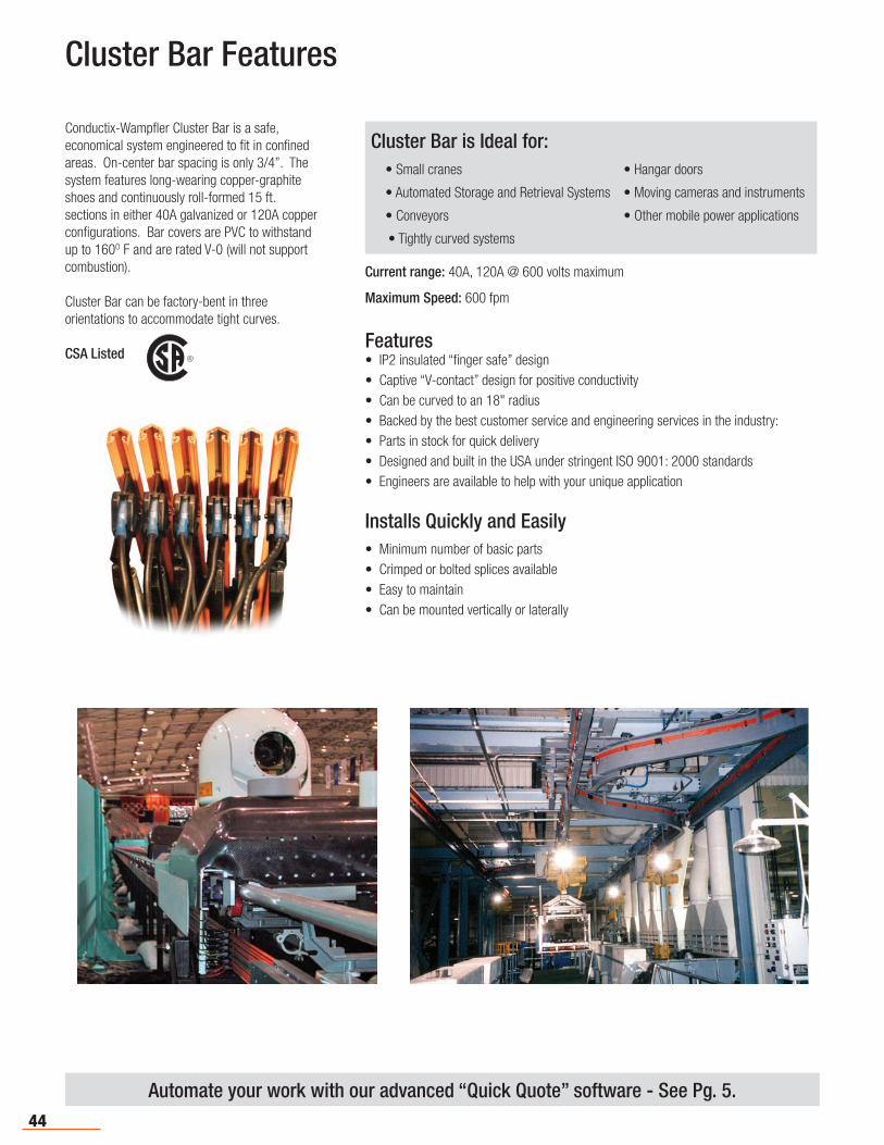
Conductix-Wampfler Cluster Bar is a safe, economical system engineered to fit in confined areas. On-center bar spacing is only 3/4”. The system features long-wearing copper-graphite shoes and continuously roll-formed 15 ft. sections in either 40A galvanized or 120A copper configurations. Bar covers are PVC to withstand up to 160O F and are rated V-0 (will not support combustion).
Cluster Bar can be factory-bent in three orientations to accommodate tight curves.
CSA Listed R
Features• IP2 insulated “finger safe” design• Captive “V-contact” design for positive conductivity • Can be curved to an 18" radius• Backed by the best customer service and engineering services in the industry:• Parts in stock for quick delivery• Designed and built in the USA under s tringent ISO 9001: 2000 standards• Engine ers are available to help with your unique application
Installs Quickly and Easily• Minimum number of basic parts• Crimped or bolted splices available • Easy to maintain• Can be mounted vertically or laterally
Current range: 40A, 120A @ 600 volts maximum
Maximum Speed: 600 fpm
Cluster Bar is Ideal for: • Small cranes • Hangar doors
• Automated Storage and Retrieval Systems • Moving cameras and instruments
• Conveyors • Other mobile power applications
• Tightly curved systems
45
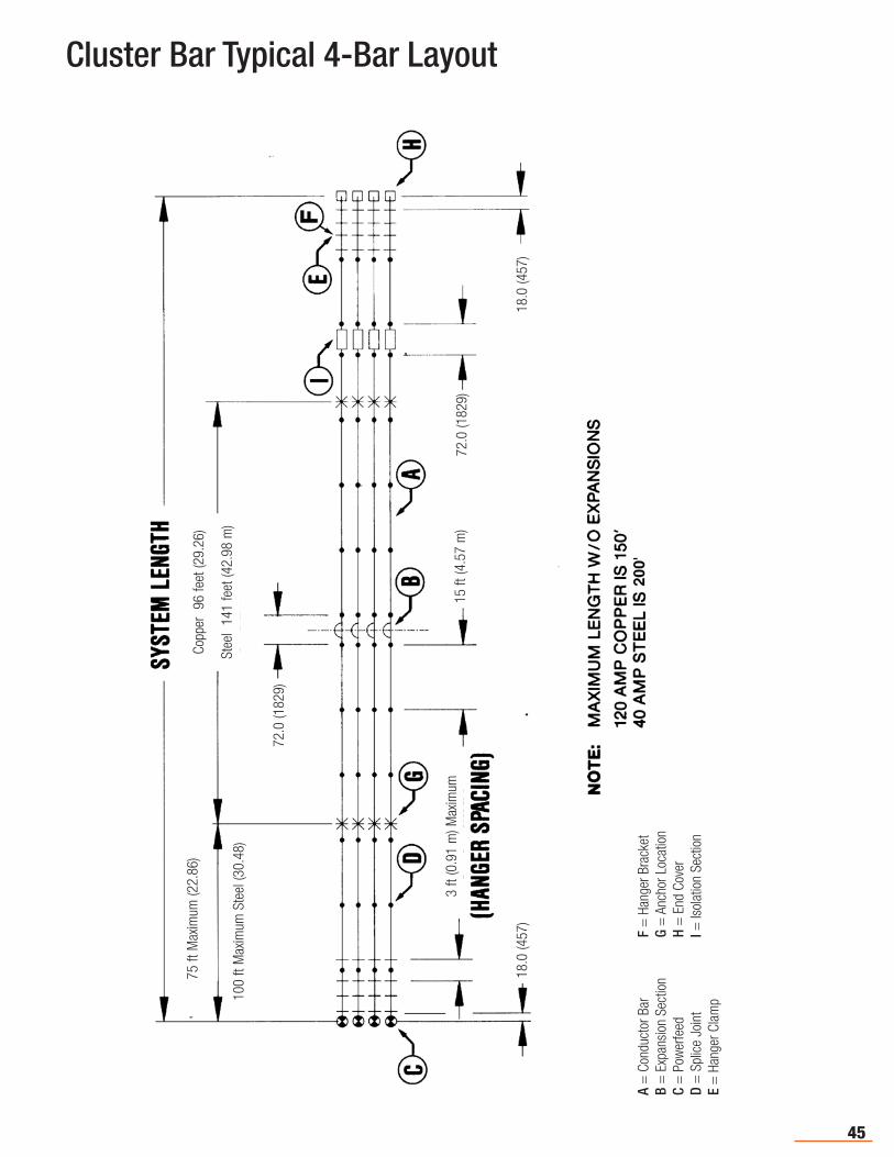
Cluster Bar Typical 4-Bar Layout
A =
Con
duct
or B
ar
F =
Han
ger B
rack
etB
= E
xpan
sion
Sec
tion
G =
Anc
hor L
ocat
ion
C =
Pow
erfe
ed
H
= E
nd C
over
D =
Spl
ice
Join
t
I = Is
olat
ion
Sect
ion
E =
Han
ger C
lam
p
18.0
(457
)
72.0
(182
9)15
ft (4
.57
m)
Copp
er 9
6 fe
et (2
9.26
)
Stee
l 14
1 fe
et (4
2.98
m)
72.0
(182
9)
3 ft
(0.9
1 m
) Max
imum
18.0
(457
)
75 ft
Max
imum
(22.
86)
100
ft M
axim
um S
teel
(30.
48)
46
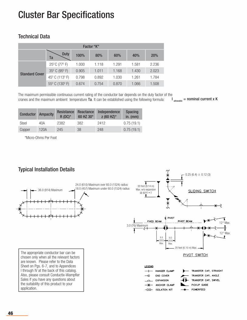
Cluster Bar Specifications
The maximum permissible continuous current rating of the conductor bar depends on the duty factor of the cranes and the maximum ambient temperature Ta. It can be established using the following formula: I allowable = nominal current x K
Technical Data
Factor “K”
100% 80% 60% 40% 20%
Standard Cover
250 C (770 F) 1.000 1.118 1.291 1.581 2.236
350 C (950 F) 0.905 1.011 1.168 1.430 2.023
450 C (1130 F) 0.798 0.892 1.030 1.261 1.784
550 C (1300 F) 0.674 0.754 0.870 1.066 1.508
DutyTa
Conductor AmpacityResistance
R (DC)*Reactance60 HZ 30*
Independencez (60 HZ)*
Spacingin. (mm)
Steel 40A 2382 382 2412 0.75 (19.1)
Copper 120A 245 38 248 0.75 (19.1)
*Micro-Ohms Per Foot
Typical Installation Details
The appropriate conductor bar can be chosen only when all the relevant factors are known. Please refer to the Data Sheet on Pgs. 6-7, and to Appendices I through IV at the back of this catalog. Also, please consult Conductix-Wampfler Sales if you have any questions about the suitability of this product to your application.
30 feet (9.14 m)Max. w/o expansion
@ 80°F T
0.25 (6.4) 0.12 (3)
3.0 (76) Maximum
20 feet (6.10 m) Max.
12 0 Max.
8.0(203)Max.
8.0(203)Max.
12 0 Max.
36.0 (914) Maximum
24.0 (610) Maximum over 60.0 (1524) radius18.0 (457) Maximum under 60.0 (1524) radius
47
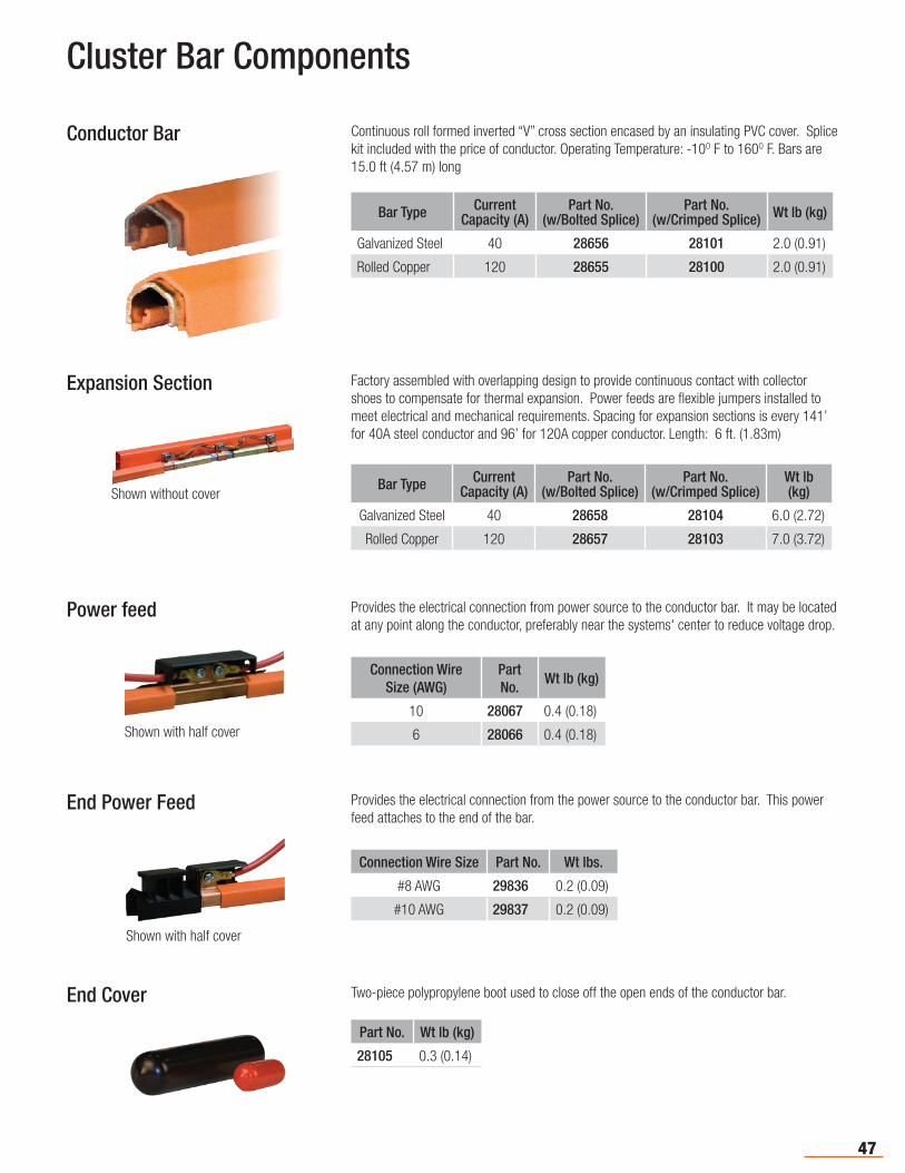
Cluster Bar Components
Conductor Bar Continuous roll formed inverted “V” cross section encased by an insulating PVC cover. Splice kit included with the price of conductor. Operating Temperature: -10O F to 160O F. Bars are 15.0 ft (4.57 m) long
Bar Type CurrentCapacity (A)
Part No.(w/Bolted Splice)
Part No.(w/Crimped Splice) Wt lb (kg)
Galvanized Steel 40 28656 28101 2.0 (0.91)
Rolled Copper 120 28655 28100 2.0 (0.91)
Expansion Section Factory assembled with overlapping design to provide continuous contact with collector shoes to compensate for thermal expansion. Power feeds are flexible jumpers installed to meet electrical and mechanical requirements. Spacing for expansion sections is every 141’ for 40A steel conductor and 96’ for 120A copper conductor. Length: 6 ft. (1.83m)
Power feed Provides the electrical connection from power source to the conductor bar. It may be located at any point along the conductor, preferably near the systems' center to reduce voltage drop.
Connection Wire Size (AWG)
Part No.
Wt lb (kg)
10 28067 0.4 (0.18)
6 28066 0.4 (0.18)
End Power Feed
Connection Wire Size Part No. Wt lbs.
#8 AWG 29836 0.2 (0.09)
#10 AWG 29837 0.2 (0.09)
Provides the electrical connection from the power source to the conductor bar. This power feed attaches to the end of the bar.
End Cover Two-piece polypropylene boot used to close off the open ends of the conductor bar.
Part No. Wt lb (kg)
28105 0.3 (0.14)
Bar Type CurrentCapacity (A)
Part No.(w/Bolted Splice)
Part No.(w/Crimped Splice)
Wt lb (kg)
Galvanized Steel 40 28658 28104 6.0 (2.72)
Rolled Copper 120 28657 28103 7.0 (3.72)
Shown without cover
Shown with half cover
Shown with half cover
48
Cluster Bar Components
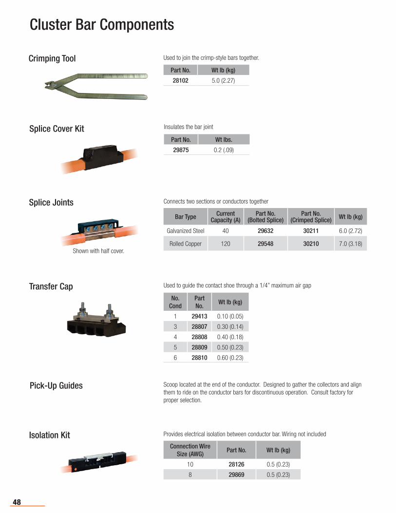
Crimping Tool Used to join the crimp-style bars together.
Part No. Wt lb (kg)
28102 5.0 (2.27)
Splice Cover Kit Insulates the bar joint
Part No. Wt lbs.
29875 0.2 (.09)
Splice Joints Connects two sections or conductors together
Bar Type CurrentCapacity (A)
Part No.(Bolted Splice)
Part No.(Crimped Splice) Wt lb (kg)
Galvanized Steel 40 29632 30211 6.0 (2.72)
Rolled Copper 120 29548 30210 7.0 (3.18)
Transfer Cap Used to guide the contact shoe through a 1/4” maximum air gap
No. Cond
Part No.
Wt lb (kg)
1 29413 0.10 (0.05)
3 28807 0.30 (0.14)
4 28808 0.40 (0.18)
5 28809 0.50 (0.23)
6 28810 0.60 (0.23)
Pick-Up Guides Scoop located at the end of the conductor. Designed to gather the collectors and align them to ride on the conductor bars for discontinuous operation. Consult factory for proper selection.
Isolation Kit Provides electrical isolation between conductor bar. Wiring not included
Connection Wire Size (AWG)
Part No. Wt lb (kg)
10 28126 0.5 (0.23)
8 29869 0.5 (0.23)
Shown with half cover.
49
Cluster Bar Components
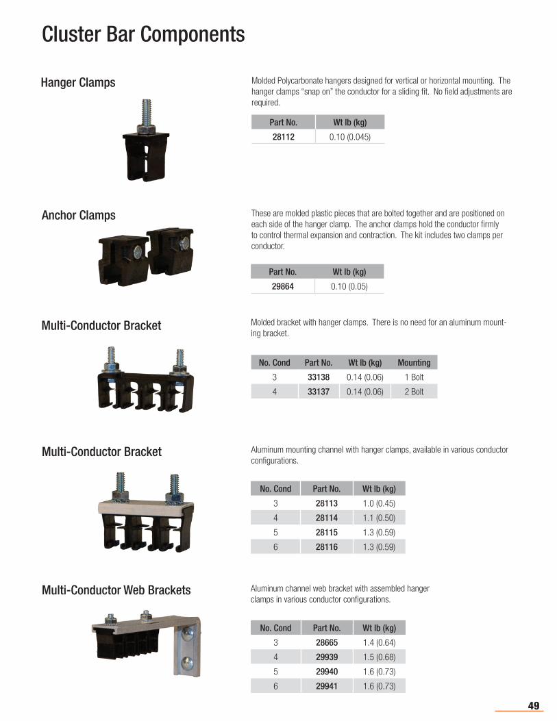
Hanger Clamps Molded Polycarbonate hangers designed for vertical or horizontal mounting. The hanger clamps “snap on” the conductor for a sliding fit. No field adjustments are required.
Anchor Clamps These are molded plastic pieces that are bolted together and are positioned on each side of the hanger clamp. The anchor clamps hold the conductor firmly to control thermal expansion and contraction. The kit includes two clamps per conductor.
Part No. Wt lb (kg)
29864 0.10 (0.05)
Multi-Conductor Bracket Molded bracket with hanger clamps. There is no need for an aluminum mount-ing bracket.
No. Cond Part No. Wt lb (kg) Mounting
3 33138 0.14 (0.06) 1 Bolt
4 33137 0.14 (0.06) 2 Bolt
Part No. Wt lb (kg)
28112 0.10 (0.045)
Multi-Conductor Bracket
No. Cond Part No. Wt lb (kg)
3 28113 1.0 (0.45)
4 28114 1.1 (0.50)
5 28115 1.3 (0.59)
6 28116 1.3 (0.59)
Aluminum mounting channel with hanger clamps, available in various conductor configurations.
Multi-Conductor Web Brackets Aluminum channel web bracket with assembled hanger clamps in various conductor configurations.
No. Cond Part No. Wt lb (kg)
3 28665 1.4 (0.64)
4 29939 1.5 (0.68)
5 29940 1.6 (0.73)
6 29941 1.6 (0.73)
50
Cluster Bar Components
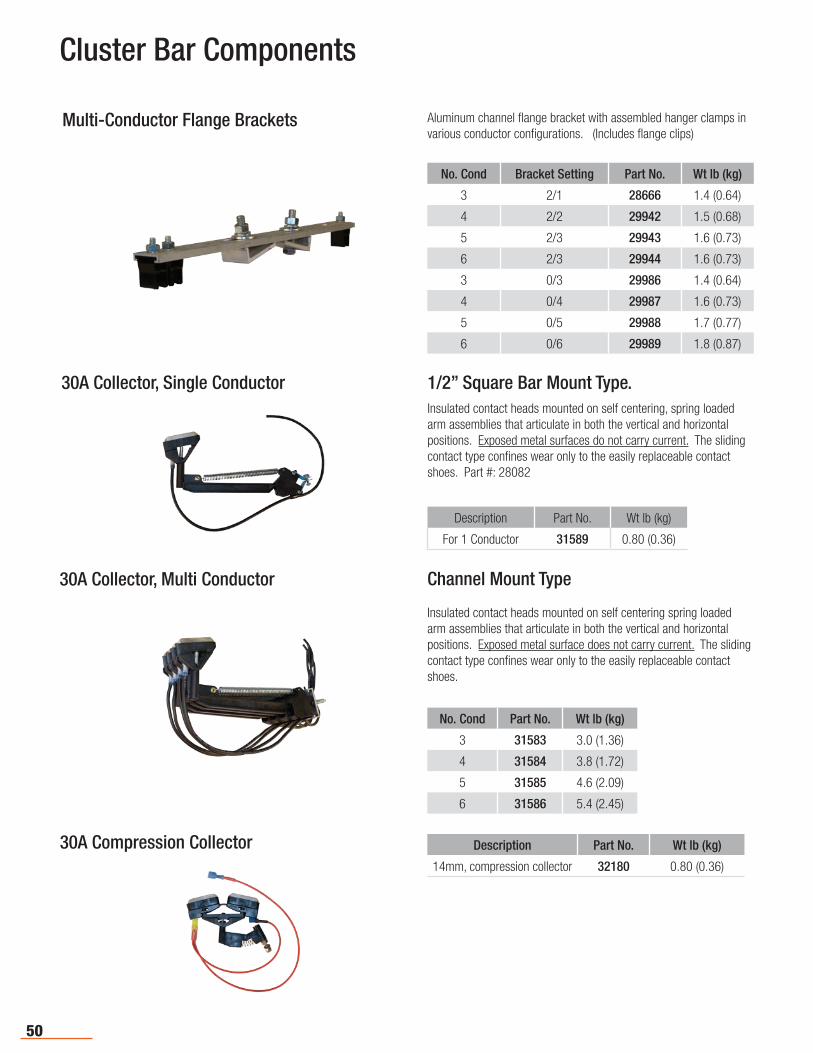
Multi-Conductor Flange Brackets
No. Cond Bracket Setting Part No. Wt lb (kg)
3 2/1 28666 1.4 (0.64)
4 2/2 29942 1.5 (0.68)
5 2/3 29943 1.6 (0.73)
6 2/3 29944 1.6 (0.73)
3 0/3 29986 1.4 (0.64)
4 0/4 29987 1.6 (0.73)
5 0/5 29988 1.7 (0.77)
6 0/6 29989 1.8 (0.87)
Aluminum channel flange bracket with assembled hanger clamps in various conductor configurations. (Includes flange clips)
30A Collector, Single Conductor 1/2” Square Bar Mount Type.Insulated contact heads mounted on self centering, spring loaded arm assemblies that articulate in both the vertical and horizontal positions. Exposed metal surfaces do not carry current. The sliding contact type confines wear only to the easily replaceable contact shoes. Part #: 28082
Description Part No. Wt lb (kg)
For 1 Conductor 31589 0.80 (0.36)
30A Collector, Multi Conductor Channel Mount Type
Insulated contact heads mounted on self centering spring loaded arm assemblies that articulate in both the vertical and horizontal positions. Exposed metal surface does not carry current. The sliding contact type confines wear only to the easily replaceable contact shoes.
No. Cond Part No. Wt lb (kg)
3 31583 3.0 (1.36)
4 31584 3.8 (1.72)
5 31585 4.6 (2.09)
6 31586 5.4 (2.45)
30A Compression Collector Description Part No. Wt lb (kg)
14mm, compression collector 32180 0.80 (0.36)
51
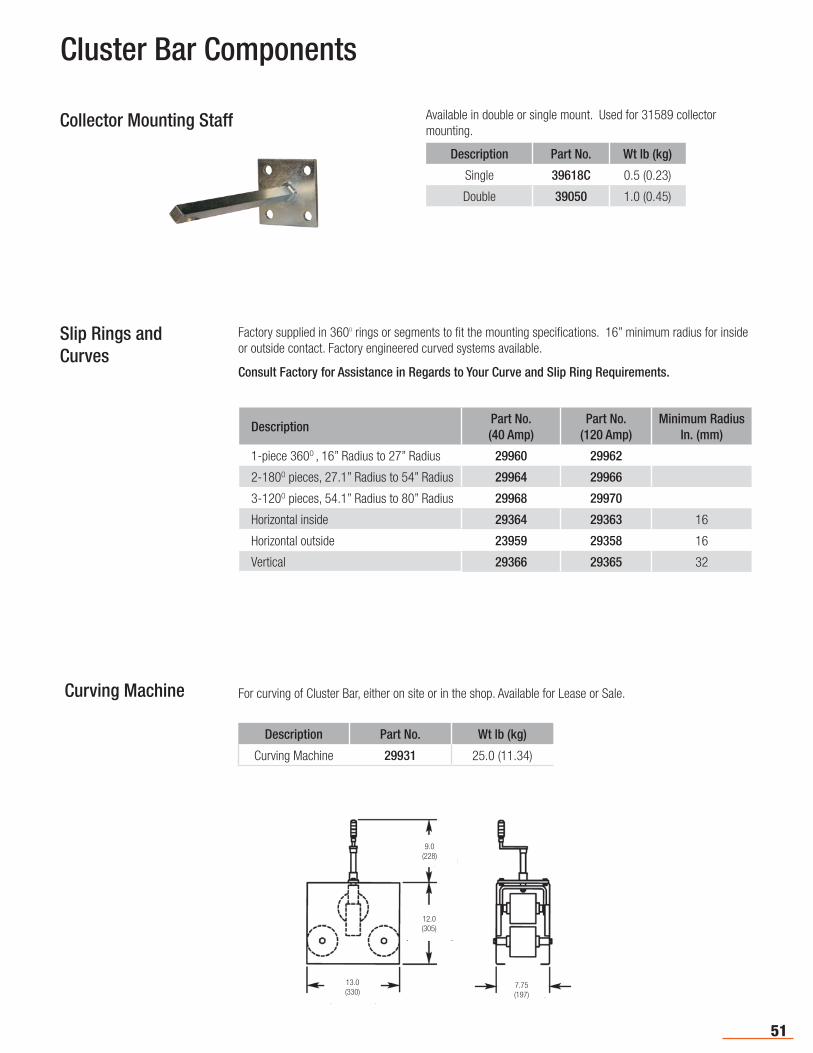
Collector Mounting Staff Available in double or single mount. Used for 31589 collector mounting.
Description Part No. Wt lb (kg)
Single 39618C 0.5 (0.23)
Double 39050 1.0 (0.45)
Cluster Bar Components
Slip Rings andCurves
Factory supplied in 360O rings or segments to fit the mounting specifications. 16” minimum radius for inside or outside contact. Factory engineered curved systems available.
Consult Factory for Assistance in Regards to Your Curve and Slip Ring Requirements.
DescriptionPart No.(40 Amp)
Part No.(120 Amp)
Minimum Radius In. (mm)
1-piece 360O , 16” Radius to 27” Radius 29960 29962
2-180O pieces, 27.1” Radius to 54” Radius 29964 29966
3-120O pieces, 54.1” Radius to 80” Radius 29968 29970
Horizontal inside 29364 29363 16
Horizontal outside 23959 29358 16
Vertical 29366 29365 32
Curving Machine
Description Part No. Wt lb (kg)
Curving Machine 29931 25.0 (11.34)
For curving of Cluster Bar, either on site or in the shop. Available for Lease or Sale.
9.0(228)
12.0(305)
7.75(197)
13.0(330)
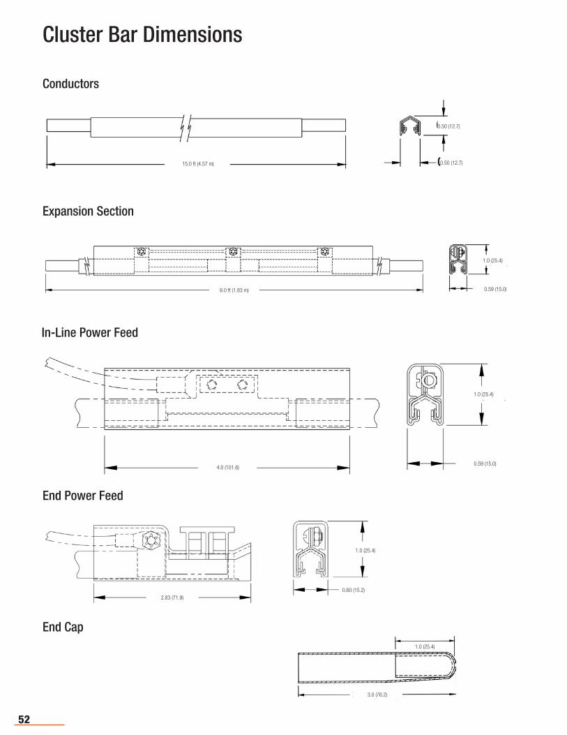
52
Cluster Bar Dimensions
15.0 ft (4.57 m)
0.50 (12.7)
0.50 (12.7)
Conductors
6.0 ft (1.83 m)
1.0 (25.4)
0.59 (15.0)
Expansion Section
4.0 (101.6)
1.0 (25.4)
0.59 (15.0)
In-Line Power Feed
2.83 (71.9) 0.60 (15.2)
1.0 (25.4)
End Power Feed
1.0 (25.4)
3.0 (76.2)
End Cap
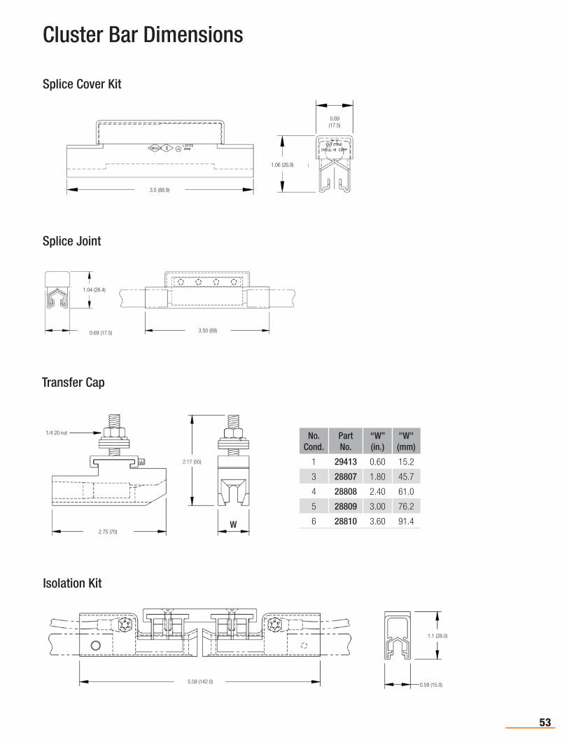
53
Cluster Bar Dimensions
3.5 (88.9)
1.06 (26.9)
0.69(17.5)
Splice Cover Kit
1.04 (26.4)
0.69 (17.5) 3.50 (89)
Splice Joint
1/4 20 nut
2.17 (55)
2.75 (70)W
Transfer Cap
5.59 (142.0)
1.1 (28.0)
0.59 (15.0)
Isolation Kit
No. Cond.
Part No.
“W”(in.)
"W"(mm)
1 29413 0.60 15.2
3 28807 1.80 45.7
4 28808 2.40 61.0
5 28809 3.00 76.2
6 28810 3.60 91.4
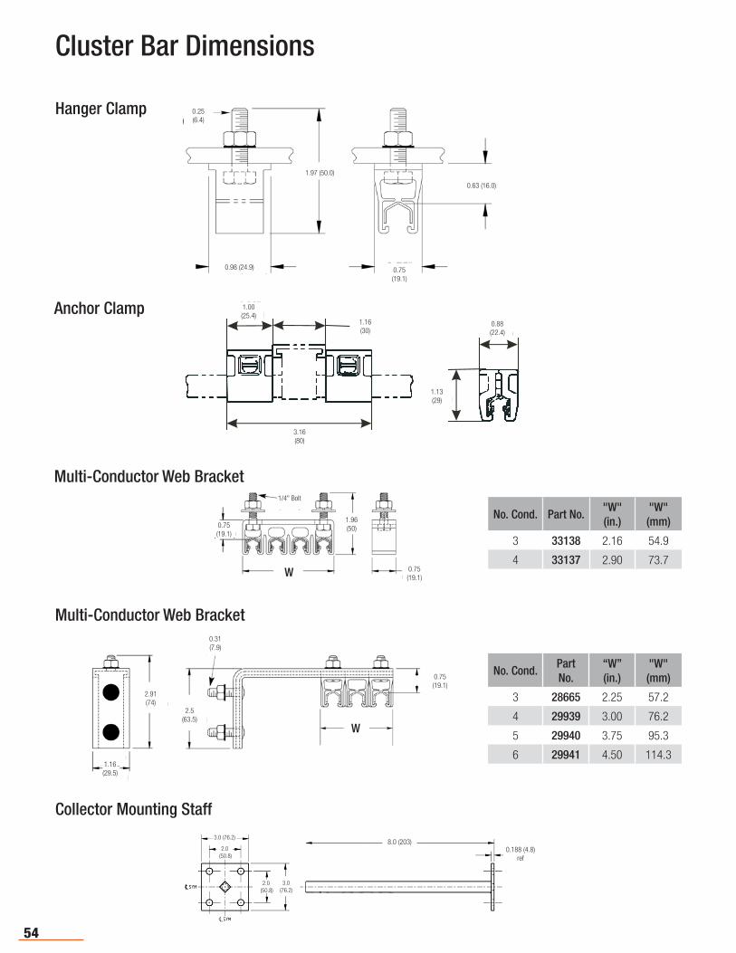
54
0.25 (6.4)
1.97 (50.0)
0.98 (24.9) 0.75(19.1)
0.63 (16.0)
Hanger Clamp
1.00(25.4)
1.16(30)
1.13(29)
0.88(22.4)
3.16(80)
Anchor Clamp
Collector Mounting Staff
Cluster Bar Dimensions
8.0 (203)0.188 (4.8)
ref
3.0 (76.2)
2.0 (50.8)
2.0 (50.8)
3.0(76.2)
1.16(29.5)
2.91(74)
2.5(63.5)
0.31(7.9)
0.75(19.1)
W
Multi-Conductor Web Bracket
No. Cond.Part No.
“W”(in.)
"W"(mm)
3 28665 2.25 57.2
4 29939 3.00 76.2
5 29940 3.75 95.3
6 29941 4.50 114.3
Multi-Conductor Web Bracket
No. Cond. Part No."W"(in.)
"W"(mm)
3 33138 2.16 54.9
4 33137 2.90 73.70.75(19.1)
1.96(50)
W
1/4" Bolt
0.75(19.1)
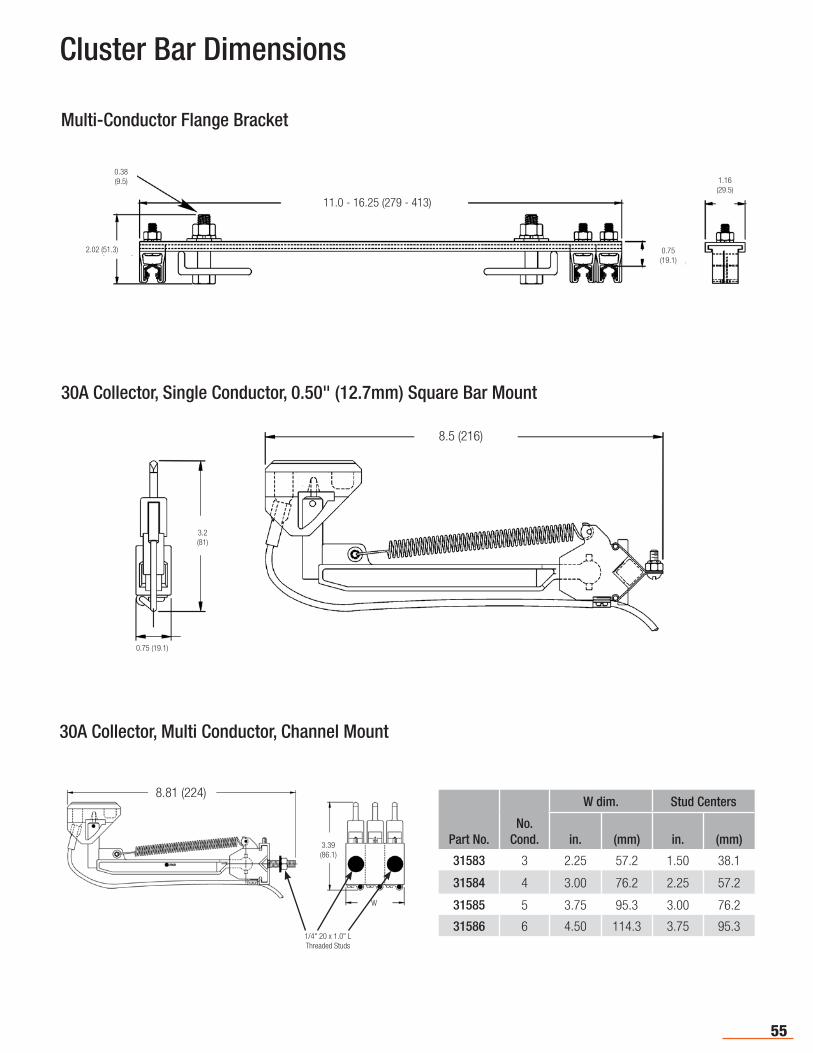
55
0.38(9.5)
2.02 (51.3)
11.0 - 16.25 (279 - 413)
0.75(19.1)
1.16(29.5)
Multi-Conductor Flange Bracket
8.5 (216)
3.2 (81)
0.75 (19.1)
30A Collector, Single Conductor, 0.50" (12.7mm) Square Bar Mount
30A Collector, Multi Conductor, Channel Mount
Cluster Bar Dimensions
Part No.No.
Cond.
W dim. Stud Centers
in. (mm) in. (mm)
31583 3 2.25 57.2 1.50 38.1
31584 4 3.00 76.2 2.25 57.2
31585 5 3.75 95.3 3.00 76.2
31586 6 4.50 114.3 3.75 95.3
8.81 (224)
3.39 (86.1)
W
1/4" 20 x 1.0" LThreaded Studs
56
The Series C range of conductor bars is available in 110 amp and 300 amp capacities and can be mounted in any plane. The "C"-shaped metal guideway provides positive tracking of the collector shoe within the profile of the bar; the shoe will track with or without the cover. The flat contact surface of the bar and copper graphite shoe yields minimal shoe wear. Skin-tight insulation runs cooler and will not deform under clamp-ing pressure. The push-pin joint system requires no loose hardware to install. C Series bars are available with standard rigid PVC insulation, or optional medium-heat Lexan or high-heat fiberglass insulation. Available accessories include single or tandem collectors, various single or multi-pole hanger clamps (3 or 4 pole), isolation sections, and expansion sections for longer runs.
Series C
Series T
The T Series system is unique to Conductix-Wampfler and features a captive collector concept resulting in an extremely compact system. The conductor bars are supplied with pre-mounted joints. Using the jointing tool, adjoining rails can be connected quickly and easily. Special spring collectors are constructed of a chromium-copper material which ensures optimized collector wear. Available in 65 amp galvanized steel with a full line of accessories.
Saf-T-Bar Features and Series
The Saf-T-Bar line of conductor bar products was originally manufactured by the Howell Corporation and is now part of the Conductix-Wampfler product family. Saf-T-Bar is designed to provide customers with a cost effective, yet highly reliable system for the transmission of electrical energy. Each system is designed with simplicity and reliability in mind. The performance of the product line has been proven in the field for over 30 years.
UL ListedCurrent range @ 600 Volts Maximum:
C Series: 110A, 300A,T Series: 65A
Maximum Speed: 900 ft/min (274 meters/min)
Saf-T-Bar® is Ideal for:• Small to Large Cranes • Hoists
• Conveyors • ASRS Systems (T Series)
• Monorails and Trolleys • Other Moving Equipment
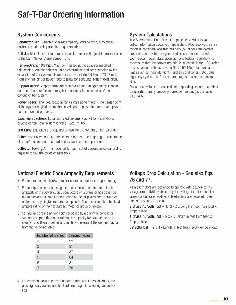
57
Saf-T-Bar Ordering Information
System Components:Conductor Bar: Selected to meet ampacity, voltage drop, duty cycle, environmental, and application requirements.
Rail Joints : Required for each connection, unless the joint is pre-mounted to the bar - Series C and Series T only.
Hanger/Anchor Clamps: Must be installed at the spacing specified in this catalog. Anchor points must be determined and set according to the expansion of the system. Hangers must be installed at least 6"(152 mm) from any rail joint or power feed to allow for adequate system expansion.
Support Arms: Support arms are required at each hanger clamp location and must be of sufficient strength to ensure safe suspension of the conductor bar system.
Power Feeds: The ideal location for a single power feed is the center point of the system to yield the minimum voltage drop. A minimum of one power feed is required per pole.
Expansion Sections: Expansion sections are required for installations beyond certain total system lengths - See Pg. 65.
End Caps: End caps are required to insulate the system at the rail ends.
Collectors: Collectors must be selected to meet the amperage requirements of crane/machine and the related duty cycle of the application.
Collector Towing Arm: Is required for each set of current collectors and is required to tow the collector assembly.
National Electric Code Ampacity Requirements1. For one motor, use 100% of motor nameplate full load ampere rating.
2. For multiple motors on a single crane or hoist, the minimum circuit ampacity of the power supply conductors on a crane or hoist shall be the nameplate full load ampere rating of the largest motor or group of motors for any single crane motion, plus 50% of the nameplate full load ampere rating of the next largest motor or group of motors.
3. For multiple cranes and/or hoists supplied by a common conductor system, compute the motor minimum ampacity for each crane as in step (2), add them together and multiply the sum of the demand factor from the following table:
4. For constant loads such as magnets, lights, and air conditioners, etc., plus high duty cycles, use full load amperage, in selecting conductor size.
Number of cranes Demand factor2 .953 .914 .875 .846 .817 .78
Voltage Drop Calculation - See also Pgs. 76 and 77.As most motors are designed to operate with a 2.5% to 5% voltage drop, divide volts lost by line voltage to determine if a larger conductor or additional feed points are required. See tables for values Z and R.3 phase AC Volts lost = 1.73 x Z x Length in feet from feed x Ampere load1 phase AC Volts lost = 2 x Z x Length in feet from feed x Ampere loadDV Volts lost = 2 x R x Length in feet from feed x Ampere load
System CalculationsThe Specification Data Sheets on pages 6-7 will help you collect information about your application. Also, see Pgs. 83-88 for other considerations that will help you choose the correct conductor bar system for your application. Please also refer to your relevant local, state/provincial, and federal regulations to make sure that the correct material is selected. In the USA, refer to calculation methods used in NEC 610-14(e). For constant loads such as magnets, lights, and air conditioners, etc., plus high duty cycles, use full load amperages to select conductor size.Once these values are determined, depending upon the ambient temperature, apply ampacity correction factors (as per table 610.14(A).
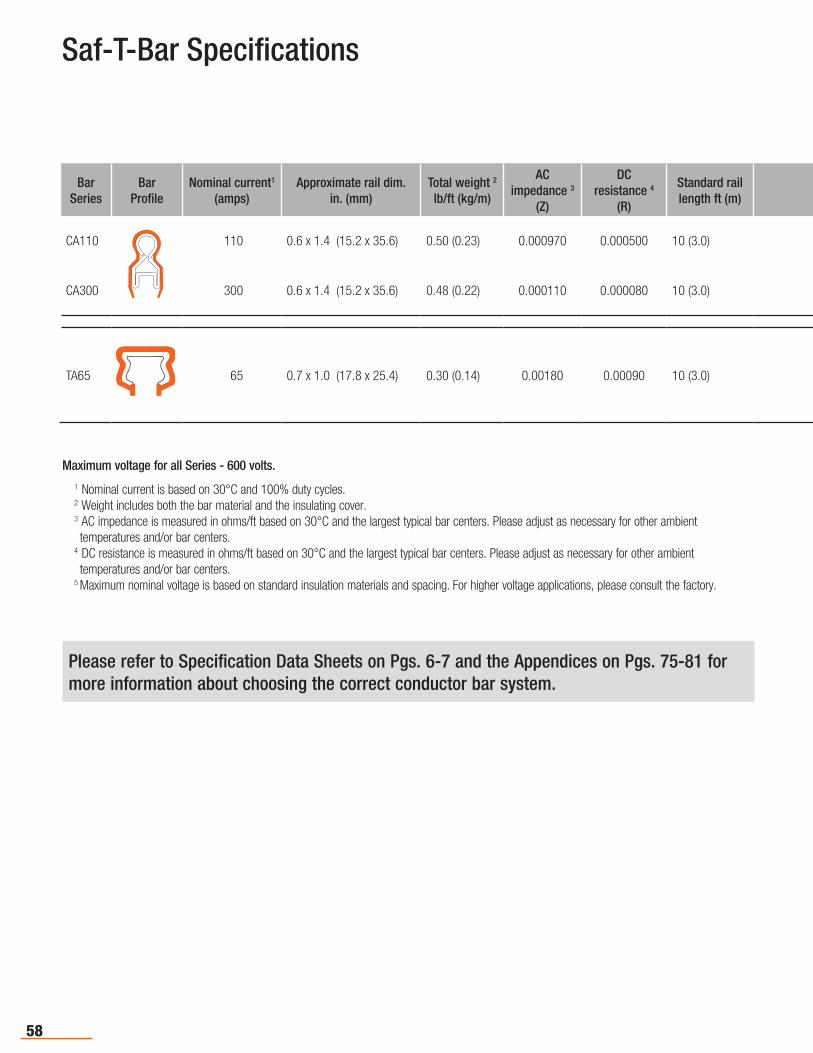
58
BarSeries
BarProfile
Nominal current1
(amps)Approximate rail dim.
in. (mm)Total weight 2 lb/ft (kg/m)
AC impedance 3
(Z)
DCresistance 4
(R)
Standard rail length ft (m)
Maximum Support Spacing ft (m)
Typical Rail Centersin. (mm)
Maximum Nominal Voltage5 High-Temp Option Outdoor Page
CA110 110 0.6 x 1.4 (15.2 x 35.6) 0.50 (0.23) 0.000970 0.000500 10 (3.0) 5 (1.5) 1.5 or 2.0 (38.1 or 50.1)600V
● ● 61
CA300 300 0.6 x 1.4 (15.2 x 35.6) 0.48 (0.22) 0.000110 0.000080 10 (3.0) 5 (1.5) 1.5 or 2.0 (38.1 or 50.1)600V
● ● 61
TA65 65 0.7 x 1.0 (17.8 x 25.4) 0.30 (0.14) 0.00180 0.00090 10 (3.0) 5 (1.5) 1 or 2 (25.4 or 50.1)600V
● 79
Saf-T-Bar Specifications
Please refer to Specification Data Sheets on Pgs. 6-7 and the Appendices on Pgs. 75-81 for more information about choosing the correct conductor bar system.
Maximum voltage for all Series - 600 volts.
1 Nominal current is based on 30°C and 100% duty cycles.2 Weight includes both the bar material and the insulating cover. 3 AC impedance is measured in ohms/ft based on 30°C and the largest typical bar centers. Please adjust as necessary for other ambient temperatures and/or bar centers.
4 DC resistance is measured in ohms/ft based on 30°C and the largest typical bar centers. Please adjust as necessary for other ambient temperatures and/or bar centers.
5 Maximum nominal voltage is based on standard insulation materials and spacing. For higher voltage applications, please consult the factory.
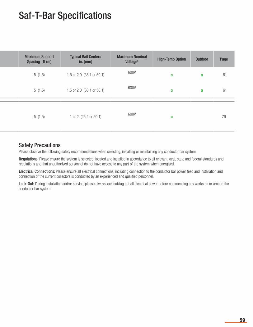
59
BarSeries
BarProfile
Nominal current1
(amps)Approximate rail dim.
in. (mm)Total weight 2 lb/ft (kg/m)
AC impedance 3
(Z)
DCresistance 4
(R)
Standard rail length ft (m)
Maximum Support Spacing ft (m)
Typical Rail Centersin. (mm)
Maximum Nominal Voltage5 High-Temp Option Outdoor Page
CA110 110 0.6 x 1.4 (15.2 x 35.6) 0.50 (0.23) 0.000970 0.000500 10 (3.0) 5 (1.5) 1.5 or 2.0 (38.1 or 50.1)600V
● ● 61
CA300 300 0.6 x 1.4 (15.2 x 35.6) 0.48 (0.22) 0.000110 0.000080 10 (3.0) 5 (1.5) 1.5 or 2.0 (38.1 or 50.1)600V
● ● 61
TA65 65 0.7 x 1.0 (17.8 x 25.4) 0.30 (0.14) 0.00180 0.00090 10 (3.0) 5 (1.5) 1 or 2 (25.4 or 50.1)600V
● 79
Safety PrecautionsPlease observe the following safety recommendations when selecting, installing or maintaining any conductor bar system.
Regulations: Please ensure the system is selected, located and installed in accordance to all relevant local, state and federal standards and regulations and that unauthorized personnel do not have access to any part of the system when energized.
Electrical Connections: Please ensure all electrical connections, including connection to the conductor bar power feed and installation and connection of the current collectors is conducted by an experienced and qualified personnel.
Lock-Out: During installation and/or service, please always lock out/tag out all electrical power before commencing any works on or around the conductor bar system.
Saf-T-Bar Specifications
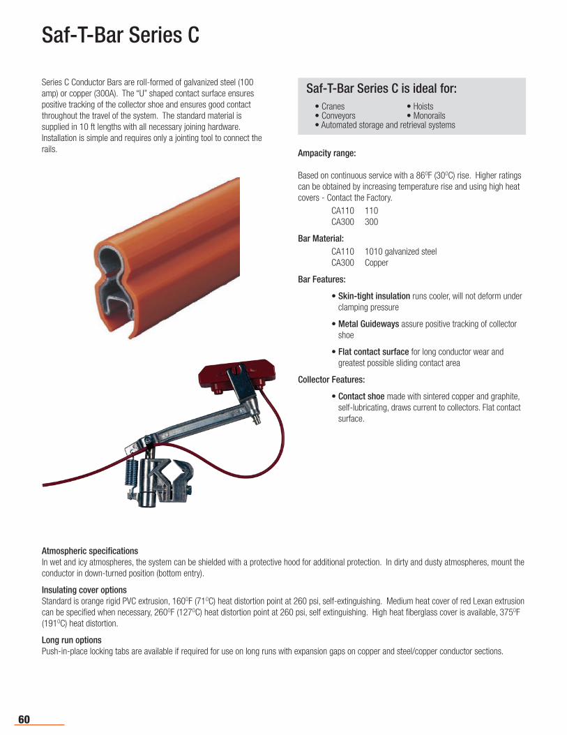
60
Saf-T-Bar Series C
Series C Conductor Bars are roll-formed of galvanized steel (100 amp) or copper (300A). The “U” shaped contact surface ensures positive tracking of the collector shoe and ensures good contact throughout the travel of the system. The standard material is supplied in 10 ft lengths with all necessary joining hardware. Installation is simple and requires only a jointing tool to connect the rails.
Saf-T-Bar Series C is ideal for:• Cranes • Hoists• Conveyors • Monorails• Automated storage and retrieval systems
Ampacity range:
Based on continuous service with a 86OF (30OC) rise. Higher ratings can be obtained by increasing temperature rise and using high heat covers - Contact the Factory. CA110 110 CA300 300
Bar Material: CA110 1010 galvanized steel CA300 Copper
Bar Features:
• Skin-tight insulation runs cooler, will not deform under clamping pressure
• Metal Guideways assure positive tracking of collector shoe
• Flat contact surface for long conductor wear and greatest possible sliding contact area
Collector Features:
• Contact shoe made with sintered copper and graphite, self-lubricating, draws current to collectors. Flat contact surface.
Atmospheric specificationsIn wet and icy atmospheres, the system can be shielded with a protective hood for additional protection. In dirty and dusty atmospheres, mount the conductor in down-turned position (bottom entry).
Insulating cover optionsStandard is orange rigid PVC extrusion, 160OF (71OC) heat distortion point at 260 psi, self-extinguishing. Medium heat cover of red Lexan extrusion can be specified when necessary, 260OF (127OC) heat distortion point at 260 psi, self extinguishing. High heat fiberglass cover is available, 375OF (191OC) heat distortion.
Long run optionsPush-in-place locking tabs are available if required for use on long runs with expansion gaps on copper and steel/copper conductor sections.
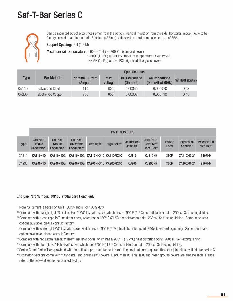
61
Saf-T-Bar Series C
1 Nominal current is based on 86OF (30°C) and is for 100% duty. 2 Complete with orange rigid "Standard Heat" PVC insulator cover, which has a 160° F (71O C) heat distortion point, 260psi. Self-extinguishing.3 Complete with green rigid PVC insulator cover, which has a 160° F (71OC) heat distortion point, 260psi. Self-extinguishing. Some hand-safe
options available, please consult Factory. 4 Complete with white rigid PVC insulator cover, which has a 160° F (71OC) heat distortion point, 260psi. Self-extinguishing. Some hand-safe
options available, please consult Factory. 5 Complete with red Lexan "Medium Heat" insulator cover, which has a 260° F (127O C) heat distortion point, 260psi. Self-extinguishing. 6 Complete with fiber glass "High Heat" cover, which has 375° F ( 191O C) heat distortion point, 260psi. Self-extinguishing. 7 Series C and Series T are provided with the rail joint pre-mounted to the rail. If special cuts are required, the extra joint kit is available for series C.8 Expansion Sections come with "Standard Heat" orange PVC covers. Medium Heat, High Heat, and green ground covers are also available. Please
refer to the relevant section or contact factory.
Type Bar Material
Specifications
Nominal Current (Amps) 1
Max.Voltage
DC Resistance (Ohms/ft)
AC impedance (Ohms/ft at 60Hz)
Wt lb/ft (kg/m)
CA110 Galvanized Steel 110 600 0.00050 0.000970 0.48
CA300 Electrolytic Copper 300 600 0.00008 0.000110 0.45
Can be mounted so collector shoes enter from the bottom (vertical mode) or from the side (horizontal mode). Able to be factory curved to a minimum of 18 inches (457mm) radius with a maximum collector size of 35A.
Support Spacing: 5 ft (1.5 M)
Maximum rail temperature: 160OF (71OC) at 260 PSI (standard cover) 260OF (127OC) at 260PSI (medium temperature Lexan cover) 375OF (191OC) at 260 PSI (high heat fiberglass cover)
PART NUMBERS
TypeStd Heat Phase
Conductor 2
Std Heat Ground
Conductor 3
Std Heat(UV White)
Conductor 4
Med Heat 5 High Heat 6 Joint/ExtraJoint Kit 7
Joint/ExtraJoint Kit 8
Med Heat
Power Feed
Expansion Section 7
Power Feed Med Heat
CA110 CA110X10 CA110X10G CA110X10G CA110HHX10 CA110FIX10 CJ110 CJ110HH 350F CA110XG-2* 350FHH
CA300 CA300X10 CA300X10G CA300X10G CA300HHX10 CA300FIX10 CJ300 CJ300HH 350F CA300XG-2* 350FHH
End Cap Part Number: CN100 ("Standard Heat" only)
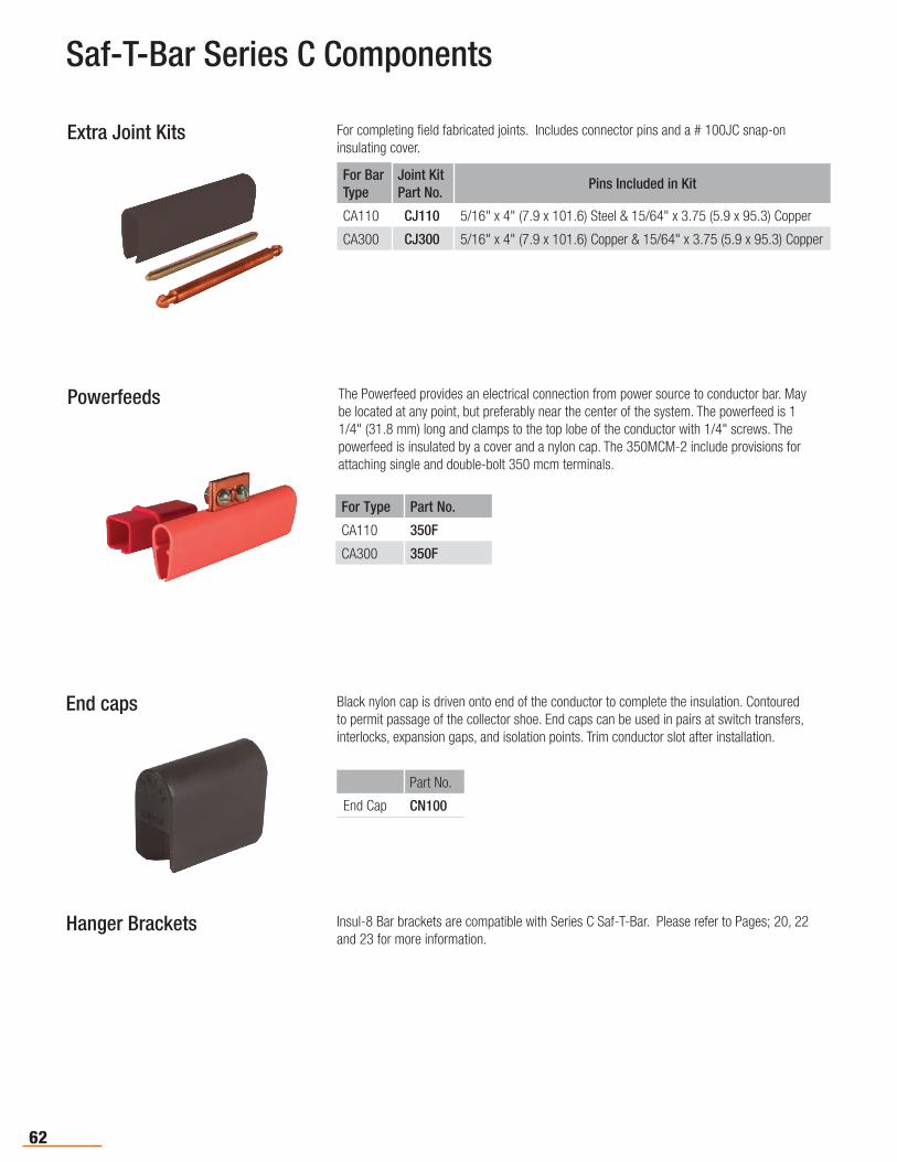
62
Saf-T-Bar Series C Components
For completing field fabricated joints. Includes connector pins and a # 100JC snap-on insulating cover.
Extra Joint Kits
For Type Part No.
CA110 350F
CA300 350F
The Powerfeed provides an electrical connection from power source to conductor bar. May be located at any point, but preferably near the center of the system. The powerfeed is 1 1/4" (31.8 mm) long and clamps to the top lobe of the conductor with 1/4" screws. The powerfeed is insulated by a cover and a nylon cap. The 350MCM-2 include provisions for attaching single and double-bolt 350 mcm terminals.
Powerfeeds
Part No.
End Cap CN100
Black nylon cap is driven onto end of the conductor to complete the insulation. Contoured to permit passage of the collector shoe. End caps can be used in pairs at switch transfers, interlocks, expansion gaps, and isolation points. Trim conductor slot after installation.
End caps
For BarType
Joint KitPart No.
Pins Included in Kit
CA110 CJ110 5/16" x 4" (7.9 x 101.6) Steel & 15/64" x 3.75 (5.9 x 95.3) Copper
CA300 CJ300 5/16" x 4" (7.9 x 101.6) Copper & 15/64" x 3.75 (5.9 x 95.3) Copper
Hanger Brackets Insul-8 Bar brackets are compatible with Series C Saf-T-Bar. Please refer to Pages; 20, 22 and 23 for more information.
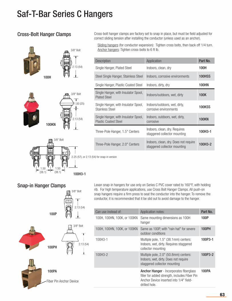
63
Saf-T-Bar Series C Hangers
Description Application Part No.
Single Hanger, Plated Steel Indoors, clean, dry 100H
Steel Single Hanger, Stainless Steel Indoors, corrosive environments 100HSS
Single Hanger, Plastic Coated Steel Indoors, dirty, dry 100HN
Single Hanger, with Insulator Spool, Plated Steel
Indoors/outdoors, wet, dirty 100K
Single Hanger, with Insulator Spool, Stainless Steel
Indoors/outdoors, wet, dirty, corrosive environments
100KSS
Single Hanger, with Insulator Spool, Plastic Coated Steel
Indoors, outdoors, wet, dirty, corrosive
100KN
Three-Pole Hanger, 1.5" CentersIndoors, clean, dry. Requires staggered collector mounting
100H3-1
Three-Pole Hanger, 2.0" CentersIndoors, clean, dry. Does not require staggered collector mounting
100H3-2
Cross-bolt hanger clamps are factory set to snap in place, but must be field adjusted for correct sliding tension after installing the conductor (unless used as an anchor).
Sliding hangers (for conductor expansion): Tighten cross bolts, then back off 1/4 turn. Anchor hangers: Tighten cross-bolts to 6 ft lb.
Cross-Bolt Hanger Clamps
100H
Can use instead of: Application notes: Part No.
100H, 100HN, 100K, or 100KN Same mounting dimensions as 100H hanger
100P
100H, 100HN, 100K, or 100KN Same as 100P, with "rain hat" for severe outdoor conditions
100PH
100H3-1 Multiple pole, 1.5" (38.1mm) centers: Indoors, wet, dirty. Requires staggered collector mounting
100P3-1
100H3-2 Multiple pole, 2.0" (50.8mm) centers: Indoors, wet, dirty. Does not require staggered collector mounting
100P3-2
Anchor Hanger - Incorporates fiberglass filler for added strength, includes Fiber Pin Anchor Device inserted into 1/4" field-drilled hole.
100PA
Lexan snap-in hangers for use only on Series C PVC cover rated to 160°F, with holding rib. For high temperature applications, use Cross Bolt Hanger Clamps. All push-on snap hangers require a firm press to seat the conductor into the hanger. To remove the conductor, it is recommended that it be slid out to avoid damage to the hanger.
3/8" Bolt
2.13 (54)
100KN
3/8" Bolt
2.13 (54)
1.00 (25)
100PA
Fiber Pin Anchor Device
3/8" Bolt
2.13 (54)
100P
Snap-in Hanger Clamps
3/8" Bolt
2.13 (54)100PH
3/8" Bolt
100H3-1
2.25 (57), or 2.13 (54) for snap-in version
1.50(38.1)
1.50(38.1)
3/8" Bolt
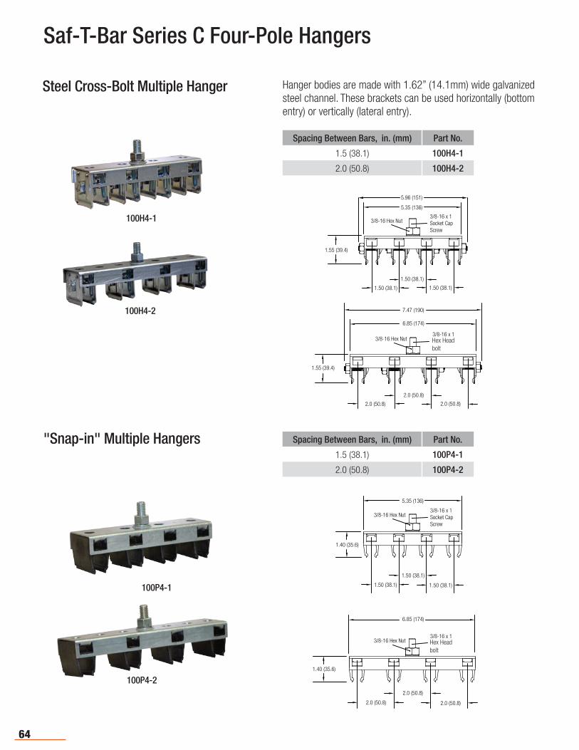
64
Hanger bodies are made with 1.62” (14.1mm) wide galvanized steel channel. These brackets can be used horizontally (bottom entry) or vertically (lateral entry).
Steel Cross-Bolt Multiple Hanger
Spacing Between Bars, in. (mm) Part No.
1.5 (38.1) 100H4-1
2.0 (50.8) 100H4-2
100H4-1
100H4-2
5.35 (136)
1.50 (38.1)
1.50 (38.1)
1.50 (38.1)
3/8-16 x 1Socket CapScrew
3/8-16 Hex Nut
5.96 (151)
1.55 (39.4)
"Snap-in" Multiple Hangers Spacing Between Bars, in. (mm) Part No.
1.5 (38.1) 100P4-1
2.0 (50.8) 100P4-2
100P4-1
100P4-2
5.35 (136)
1.40 (35.6)
1.50 (38.1)
1.50 (38.1)
1.50 (38.1)
3/8-16 x 1Socket CapScrew
3/8-16 Hex Nut
Saf-T-Bar Series C Four-Pole Hangers
6.85 (174)
1.40 (35.6)
2.0 (50.8)
2.0 (50.8)
2.0 (50.8)
3/8-16 x 1Socket CapScrew
3/8-16 Hex Nut Hex Headbolt
6.85 (174)
7.47 (190)
1.55 (39.4)
2.0 (50.8)
2.0 (50.8)
2.0 (50.8)
3/8-16 x 1Socket CapScrew
3/8-16 Hex Nut Hex Headbolt
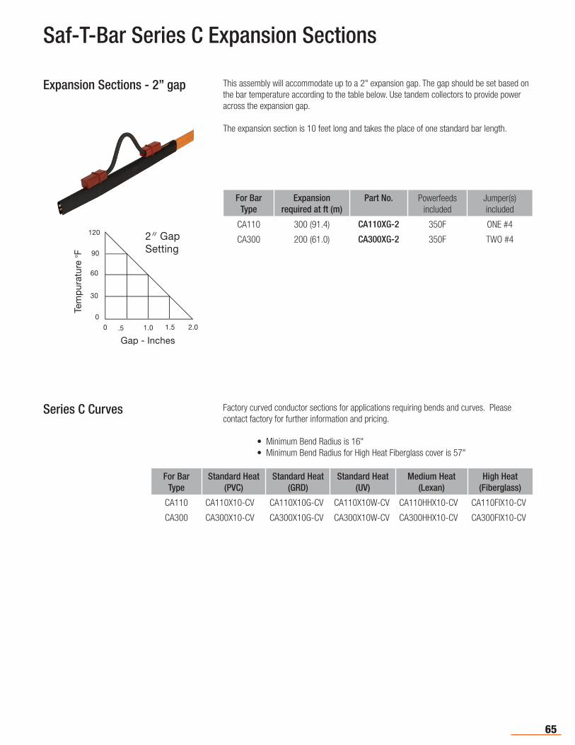
65
Saf-T-Bar Series C Expansion Sections
This assembly will accommodate up to a 2" expansion gap. The gap should be set based on the bar temperature according to the table below. Use tandem collectors to provide power across the expansion gap.
The expansion section is 10 feet long and takes the place of one standard bar length.
Expansion Sections - 2” gap
For Bar Type
Expansion required at ft (m)
Part No. Powerfeeds included
Jumper(s) included
CA110 300 (91.4) CA110XG-2 350F ONE #4
CA300 200 (61.0) CA300XG-2 350F TWO #4
Series C Curves Factory curved conductor sections for applications requiring bends and curves. Please contact factory for further information and pricing.
• Minimum Bend Radius is 16" • Minimum Bend Radius for High Heat Fiberglass cover is 57"
For Bar Type
Standard Heat (PVC)
Standard Heat (GRD)
Standard Heat (UV)
Medium Heat (Lexan)
High Heat (Fiberglass)
CA110 CA110X10-CV CA110X10G-CV CA110X10W-CV CA110HHX10-CV CA110FIX10-CV
CA300 CA300X10-CV CA300X10G-CV CA300X10W-CV CA300HHX10-CV CA300FIX10-CV

66
Saf-T-Bar Series C Collectors
Standard Arm (70E)
Self-centering, Standard Arm(100C)
Self-centering Long Arm (70LC)
Part No.
Collector Type 35A 70A 150A 100A
Standard Arm 35E 70E 150E 100E
Long Arm 35L 70L 150L 100L
Standard Arm, Self-Centering - - - 100C
Long Arm, Self-Centering - - - 100LC
Dual-Head (Tandem), Long Arm 35W 70LL 150LL 100W
Dual-Head (Tandem), Long Arm, Self-Centering - - - 100LLC
Pigtails2 10wire
(35A)2 6wire(70A)
2 4wire(150A)
2 6wire(100A)
(35E)
Dual Head Standard (35W)
Standard Arm Collectors (E) are recommended for general use on cranes and stable monorails. Also available in a self-centering version for use with Pick Up Guides - See Pg. 69.
Long Arm Collectors (L) are used where there is excessive motion vertically or horizontally (as with a swaying hoist) and for high-speed applications. Also available in a self-centering version for use with Pick Up Guides - See Pg. 69.
Self-Centering Collectors, have centering attachments for discontinuous circuits.
Dual-Head (Tandem) Collectors are available in long arm (W or LL), and long arm self-centering (LLC) versions depending on ampacity. Dual Head Collectors maintain full shoe contact through gaps (i.e. Expansion Gaps) and apply less pressure per length of bar. These are also used to obtain higher amperage than single collectors. Tandem collections must be mounted on 2" (50.8 mm) centers.
* Pigtails not included with 70A or 150A collectors. These will need to be ordered separate.
Dual-Head, Long Arm (70LL)
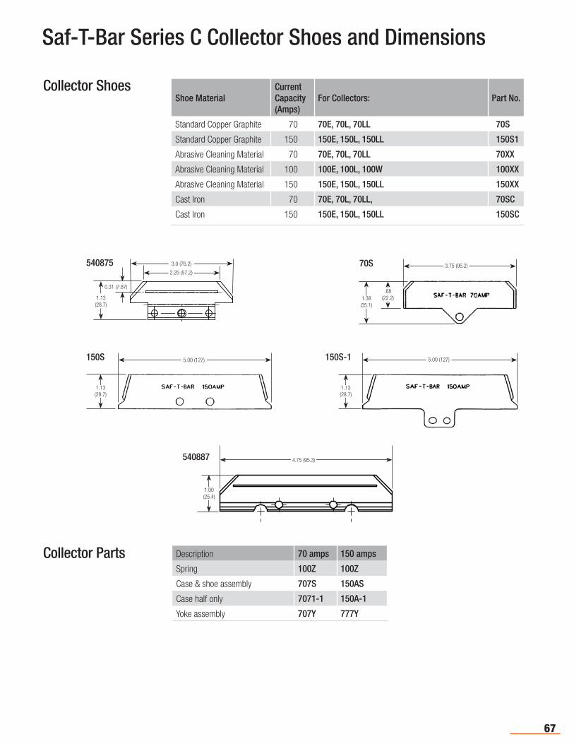
67
Description 70 amps 150 amps
Spring 100Z 100Z
Case & shoe assembly 707S 150AS
Case half only 7071-1 150A-1
Yoke assembly 707Y 777Y
Saf-T-Bar Series C Collector Shoes and Dimensions
Collector Parts
Shoe MaterialCurrent Capacity (Amps)
For Collectors: Part No.
Standard Copper Graphite 70 70E, 70L, 70LL 70S
Standard Copper Graphite 150 150E, 150L, 150LL 150S1
Abrasive Cleaning Material 70 70E, 70L, 70LL 70XX
Abrasive Cleaning Material 100 100E, 100L, 100W 100XX
Abrasive Cleaning Material 150 150E, 150L, 150LL 150XX
Cast Iron 70 70E, 70L, 70LL, 70SC
Cast Iron 150 150E, 150L, 150LL 150SC
Collector Shoes
3.0 (76.2)
0.31 (7.87)
1.13(28.7)
540875 3.75 (95.2)
.88(22.2)1.38
(35.1)
70S
5.00 (127)
1.13(28.7)
150S 5.00 (127)
1.13(28.7)
150S-1
1.00(25.4)
4.75 (95.3)540887
2.25 (57.2)
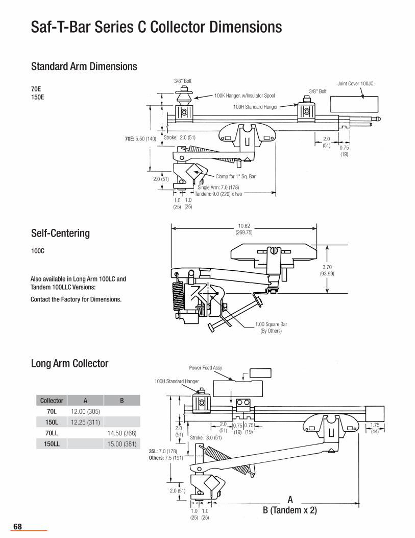
68
Long Arm Collector Power Feed Assy
100H Standard Hanger
2.0(51)
35L: 7.0 (178)Others: 7.5 (191)
Stroke: 3.0 (51)
1.75(44)
A2.0 (51)
1.0(25)
1.0(25)
2.0(51)
0.75(19)
0.75(19)
B (Tandem x 2)
Collector A B
70L 12.00 (305)
150L 12.25 (311)
70LL 14.50 (368)
150LL 15.00 (381)
Self-Centering
100C
Also available in Long Arm 100LC and Tandem 100LLC Versions:
Contact the Factory for Dimensions.
Saf-T-Bar Series C Collector Dimensions
Standard Arm Dimensions
70E150E
3/8" Bolt
70E: 5.50 (140)
100K Hanger, w/Insulator Spool
100H Standard Hanger
3/8" Bolt
Clamp for 1" Sq. Bar
Stroke: 2.0 (51)
2.0 (51)
Single Arm: 7.0 (178)Tandem: 9.0 (229) x two
Joint Cover 100JC
2.0(51) 0.75
(19)
1.0(25)
1.0(25)
10.62(269.75)
3.70(93.99)
1.00 Square Bar(By Others)

69
Amp Range Drag Shoe Length
Contour Curves? Shoe Thickness
Part No. Case #
100-150 Normal 4.375 Blunt None 0.21 150SI 150A
50-100 Normal 3.75 Tapered None 0.19 70S 707-1
25-50 Light 3.00 Blunt Short 0.19 35S 401A
100-125 Normal 3.75 Blunt None 0.225 100S 601A100
Saf-T-Bar Series C Components
Used to electrically isolate adjacent conductor sections with a 1/2” over surface gap. The sleeve will support adjacent conductor sections, but must have hangers within 6” on each side of the isolation sleeve. Collectors bridge the gap electrically. Two sleeves separated by 6” of conductor are required to prevent collectors from bridging the gap as in signal or control functions.
Isolation Sleeve
Part No.
Pick-up Guide CP100
Used for discontinuous circuits such as bridge controls, runway circuits at fire doors, etc., to allow collector to leave conductor and be realigned on return. Works with all bar capacities. Use with self-centering collectors only.
The guide is provided with hanger clamp and end cap. The guide itself is secured to the bracket with a 3/8" bolt and the conductor is secured to the guide with a hanger clamp. Conductors must be mounted on 3" (76 mm) centers minimum. Install conductorone inch into guide throat.
Pick-up Guides
Collector Shoes
Part No.
Isolation Sleeve CA100IS
Used to track the collector through bar misalignments of 1/8” to ½” (3-13 mm) laterally and of up to 1/8” in the direction of contact. Self-centering collectors are not required, but dual collectors are required if power interruption cannot be tolerated.
Conductors must be mounted on 3" (76 mm) centers minimum. Install conductor 1-1/2” (38 mm) into guide throat.
Transfer Guides
Part No.
Transfer Guide CT100
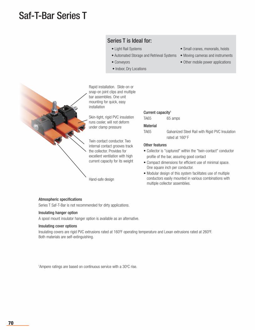
70
Saf-T-Bar Series T
Current capacity1 TA65 65 amps
MaterialTA65 Galvanized Steel Rail with Rigid PVC Insulation
rated at 1600 F
Other features• Collector is "captured" within the "twin-contact" conductor
profile of the bar , assuring good contact• Compact dimensions for efficient use of minimal space.
One square inch per conductor.• Modular design of this system facilitates use of multiple
conductors easily mounted in various combinations with multiple collector assemblies.
1Ampere ratings are based on continuous service with a 30oC rise.
Skin-tight, rigid PVC insulation runs cooler, will not deform under clamp pressure
Twin contact conductor. Two internal contact grooves track the collector. Provides for excellent ventilation with high current capacity for its weight
Rapid installation. Slide-on or snap-on joint clips and multiple bar assemblies. One unit mounting for quick, easy installation
Hand-safe design
Atmospheric specificationsSeries T Saf-T-Bar is not recommended for dirty applications.
Insulating hanger optionA spool mount insulator hanger option is available as an alternative.
Insulating cover optionsInsulating covers are rigid PVC extrusions rated at 160oF operating temperature and Lexan extrusions rated at 260oF. Both materials are self-extinguishing.
Series T is Ideal for: • Light Rail Systems • Small cranes, monorails, hoists
• Automated Storage and Retrieval Systems • Moving cameras and instruments
• Conveyors • Other mobile power applications
• Indoor, Dry Locations
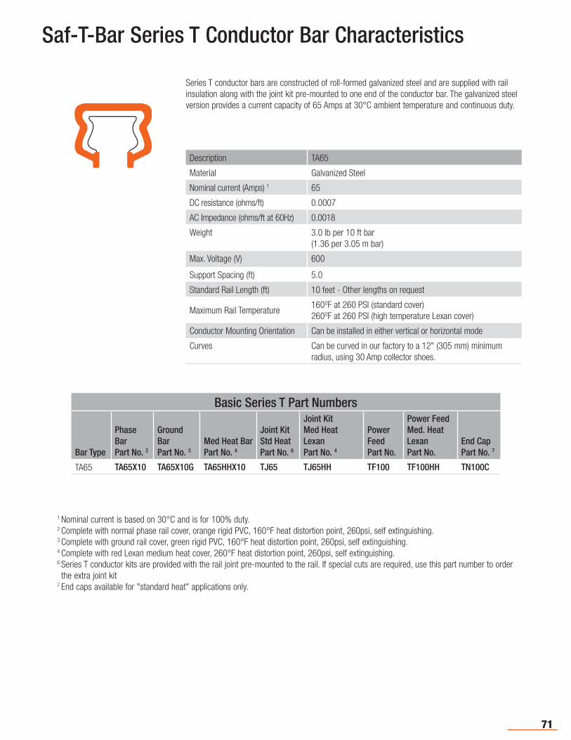
71
Saf-T-Bar Series T Conductor Bar Characteristics
Series T conductor bars are constructed of roll-formed galvanized steel and are supplied with rail insulation along with the joint kit pre-mounted to one end of the conductor bar. The galvanized steel version provides a current capacity of 65 Amps at 30°C ambient temperature and continuous duty.
1 Nominal current is based on 30°C and is for 100% duty. 2 Complete with normal phase rail cover, orange rigid PVC, 160°F heat distortion point, 260psi, self extinguishing.3 Complete with ground rail cover, green rigid PVC, 160°F heat distortion point, 260psi, self extinguishing.4 Complete with red Lexan medium heat cover, 260°F heat distortion point, 260psi, self extinguishing. 6 Series T conductor kits are provided with the rail joint pre-mounted to the rail. If special cuts are required, use this part number to order the extra joint kit
7 End caps available for "standard heat" applications only.
Description TA65
Material Galvanized Steel
Nominal current (Amps) 1 65
DC resistance (ohms/ft) 0.0007
AC Impedance (ohms/ft at 60Hz) 0.0018
Weight 3.0 lb per 10 ft bar(1.36 per 3.05 m bar)
Max. Voltage (V) 600
Support Spacing (ft) 5.0
Standard Rail Length (ft) 10 feet - Other lengths on request
Maximum Rail Temperature160OF at 260 PSI (standard cover)260OF at 260 PSI (high temperature Lexan cover)
Conductor Mounting Orientation Can be installed in either vertical or horizontal mode
Curves Can be curved in our factory to a 12" (305 mm) minimum radius, using 30 Amp collector shoes.
Basic Series T Part Numbers
Bar Type
Phase BarPart No. 2
Ground BarPart No. 3
Med Heat BarPart No. 4
Joint KitStd Heat Part No. 6
Joint KitMed Heat LexanPart No. 4
Power FeedPart No.
Power Feed Med. Heat LexanPart No.
End CapPart No. 7
TA65 TA65X10 TA65X10G TA65HHX10 TJ65 TJ65HH TF100 TF100HH TN100C
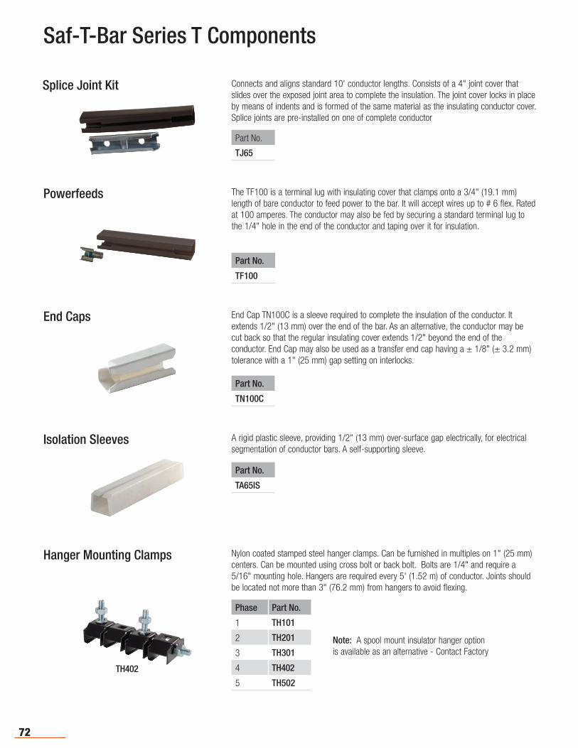
72
Connects and aligns standard 10' conductor lengths. Consists of a 4" joint cover that slides over the exposed joint area to complete the insulation. The joint cover locks in placeby means of indents and is formed of the same material as the insulating conductor cover. Splice joints are pre-installed on one of complete conductor
Saf-T-Bar Series T Components
The TF100 is a terminal lug with insulating cover that clamps onto a 3/4" (19.1 mm) length of bare conductor to feed power to the bar. It will accept wires up to # 6 flex. Rated at 100 amperes. The conductor may also be fed by securing a standard terminal lug to the 1/4" hole in the end of the conductor and taping over it for insulation.
End Cap TN100C is a sleeve required to complete the insulation of the conductor. It extends 1/2" (13 mm) over the end of the bar. As an alternative, the conductor may be cut back so that the regular insulating cover extends 1/2" beyond the end of the conductor. End Cap may also be used as a transfer end cap having a ± 1/8" (± 3.2 mm) tolerance with a 1" (25 mm) gap setting on interlocks.
A rigid plastic sleeve, providing 1/2" (13 mm) over-surface gap electrically, for electrical segmentation of conductor bars. A self-supporting sleeve.
TH402
Nylon coated stamped steel hanger clamps. Can be furnished in multiples on 1" (25 mm) centers. Can be mounted using cross bolt or back bolt. Bolts are 1/4" and require a 5/16" mounting hole. Hangers are required every 5' (1.52 m) of conductor. Joints should be located not more than 3" (76.2 mm) from hangers to avoid flexing.
Splice Joint Kit
Part No.
TJ65
Powerfeeds
Part No.
TF100
End Caps
Part No.
TN100C
Isolation Sleeves
Part No.
TA65IS
Hanger Mounting Clamps
Phase Part No.
1 TH101
2 TH201
3 TH301
4 TH402
5 TH502
Note: A spool mount insulator hanger option is available as an alternative - Contact Factory
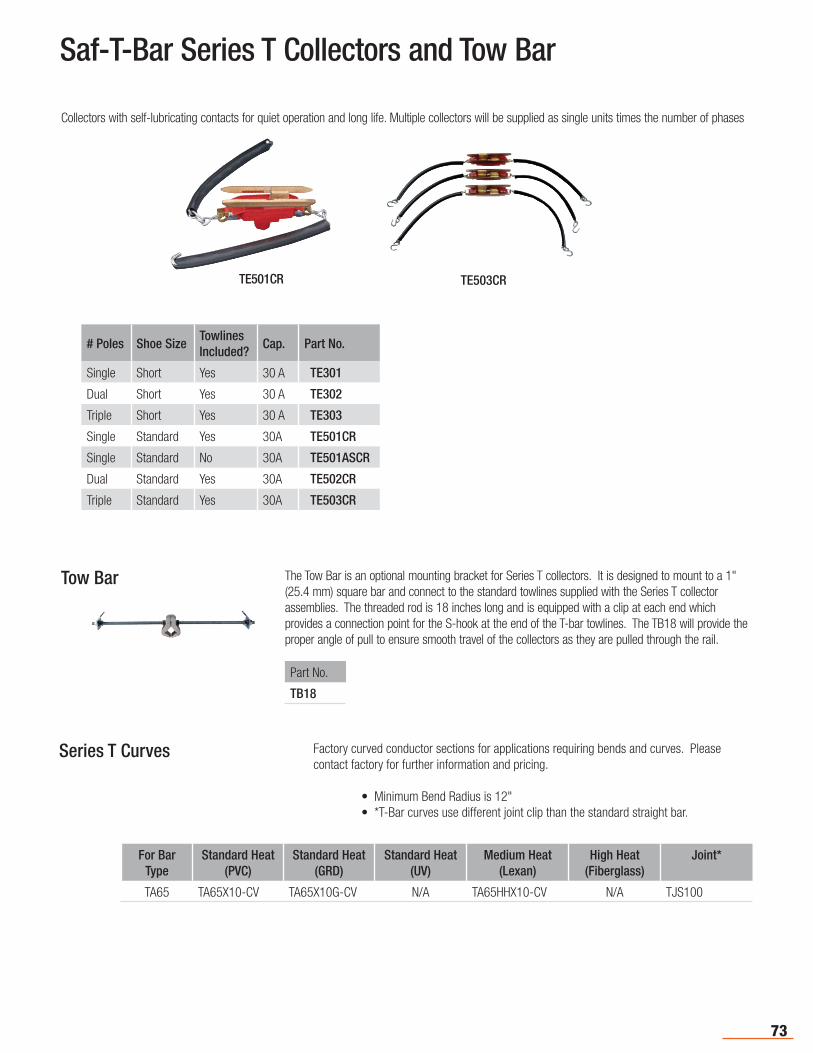
73
TE503CR
Saf-T-Bar Series T Collectors and Tow Bar
The Tow Bar is an optional mounting bracket for Series T collectors. It is designed to mount to a 1" (25.4 mm) square bar and connect to the standard towlines supplied with the Series T collector assemblies. The threaded rod is 18 inches long and is equipped with a clip at each end which provides a connection point for the S-hook at the end of the T-bar towlines. The TB18 will provide the proper angle of pull to ensure smooth travel of the collectors as they are pulled through the rail.
TE501CR
Collectors with self-lubricating contacts for quiet operation and long life. Multiple collectors will be supplied as single units times the number of phases
# Poles Shoe SizeTowlines Included?
Cap. Part No.
Single Short Yes 30 A TE301
Dual Short Yes 30 A TE302
Triple Short Yes 30 A TE303
Single Standard Yes 30A TE501CR
Single Standard No 30A TE501ASCR
Dual Standard Yes 30A TE502CR
Triple Standard Yes 30A TE503CR
Tow Bar
Part No.
TB18
Series T Curves Factory curved conductor sections for applications requiring bends and curves. Please contact factory for further information and pricing.
• Minimum Bend Radius is 12" • *T-Bar curves use different joint clip than the standard straight bar.
For Bar Type
Standard Heat (PVC)
Standard Heat (GRD)
Standard Heat (UV)
Medium Heat (Lexan)
High Heat (Fiberglass)
Joint*
TA65 TA65X10-CV TA65X10G-CV N/A TA65HHX10-CV N/A TJS100
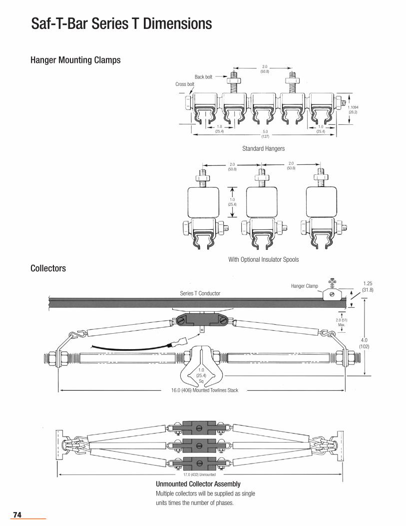
74
Saf-T-Bar Series T Dimensions
Hanger Mounting Clamps
Collectors
2.0(50.8)
2.0(50.8)
1.0(25.4)
With Optional Insulator Spools
Standard Hangers
Back bolt
2.0(50.8)
Cross bolt
1.1094(28.2)
1.0(25.4)
1.0(25.4)5.0
(127)
Unmounted Collector AssemblyMultiple collectors will be supplied as single units times the number of phases.
17.0 (432) Unmounted
Hanger Clamp
Series T Conductor
1.25 (31.8)
4.0 (102)
2.0 (51)Max.
16.0 (406) Mounted Towlines Stack
1.0(25.4)
Sq

75
Appendix I - Selection of Systems
Carefully review your equipment and application to chose the correct system and reduce the risk of system failures, equipment downtime, and maintenance time and expense. There are eight interrelated factors that should be considered when selecting the correct system.
Environmental Conditions • Freezing Conditions - Might require a heater wire to keep the conductor contact surface free from ice.
• Water and/or Dust - Might adversely affect components and might require the use of insulated hangers to better isolate the “live” conductors from ground.
• Chemicals – Can adversely affect system components. Acidic or basic fumes may require stainless steel hardware and components. With the Hevi-Bar II system, you may want to consider the optional “Dura-Coat” treatment to reduce component corrosion. This is available for 8-bar; contact the Factory for details.
• Cutting Oils – May negatively affect polycarbonate components
• Radiation - May require the use of non-PVC components and non-galvanized plated components.
Mounting and Installation • Bottom Entry – Puts the running surface on the bottom side of the conductor, which keeps dust, water, or debris away.
• Lateral (or side) Entry – Can be used if space is limited. Lateral mounting is not recommended for dusty, outdoor, or wet conditions. You may be able to stagger the collectors to decrease the space required for the system.
• Installation – Collector Arms are designed to accommodate a certain amount of movement or misalignments between the crane/vehicle and the conductor. However, if misalignments are excessive the collector could disengage from the bar.
Poor collector installation is the single greatest cause of new system problems. Installation Instructions should be strictly followed to optimize system performance and prevent problems. Manuals are available at www.conductix.us.
Number of Power and Bonding Conductors Required • Power Legs - Each “power leg” requires one run of bar
• Bonding (Ground) Bar - Per article 610.61 (National Electrical Code): “The trolley frame and bridge frame shall not be considered as electrically grounded through the bridge and trolley wheels and its respective tracks. A separate bonding conductor shall be provided”. A bonding bar is required for all overhead cranes built after 2004.
Moving Versus Stationary Applications • Moving Machine - Draws maximum power as it moves. Current-induced heat is dissipated over a wider area of the conductor.
• Stationary Machine - Draws maximum power while stationary for extended periods (e.g.: welding stations, testing equipment, or cranes that repeatedly lift in the same location). Current-induced heat is not easily dissipated when collectors are stationary. In these cases, verify that the collectors and conductors are adequate for the application.
Current and Voltage Requirements The purchase of a new conductor system affords the opportunity to size the system for additional cranes or larger cranes that may be added in the future. A small investment now could avoid major investments in the future.
• Conductor Bar Rating – Per NEC Article 610-14, the bar must accommodate 100% of the current of all the largest motors involved in a single movement, plus 50% of the next largest motors. The auxiliary hoist motor must be included if it works in conjunction with the main hoist. The system also must accommodate 100% the current draw of auxiliary equipment such as magnets, lighting, air conditioners, etc. that operate when the largest motors are energized.
• Multiple Cranes on a Single Runway – Sum the amperage requirements of each crane, then apply the appropriate “diversity factor” (NEC Table 610-14e). All cranes do not pull the maximum load all the time or pull the load at the same time.
• Two Cranes Working in Tandem - Do not apply the diversity factor, since both run at the same time. See Specification Data Sheet, Pgs. 6-7 for further “total load” calculation details.
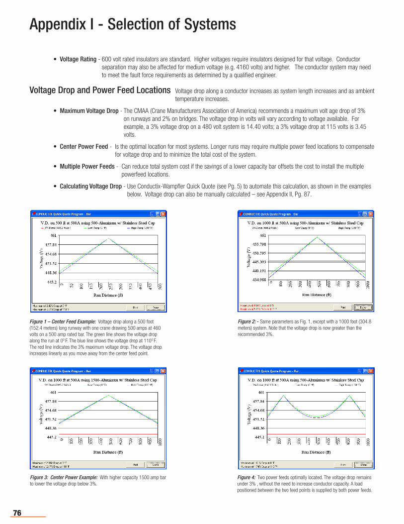
76
• Voltage Rating - 600 volt rated insulators are standard. Higher voltages require insulators designed for that voltage. Conductor separation may also be affected for medium voltage (e.g. 4160 volts) and higher. The conductor system may need to meet the fault force requirements as determined by a qualified engineer.
Voltage Drop and Power Feed Locations Voltage drop along a conductor increases as system length increases and as ambient temperature increases.
• Maximum Voltage Drop - The CMAA (Crane Manufacturers Association of America) recommends a maximum volt age drop of 3% on runways and 2% on bridges. The voltage drop in volts will vary according to voltage available. For example, a 3% voltage drop on a 480 volt system is 14.40 volts; a 3% voltage drop at 115 volts is 3.45 volts.
• Center Power Feed - Is the optimal location for most systems. Longer runs may require multiple power feed locations to compensate for voltage drop and to minimize the total cost of the system.
• Multiple Power Feeds - Can reduce total system cost if the savings of a lower capacity bar offsets the cost to install the multiple powerfeed locations.
• Calculating Voltage Drop - Use Conductix-Wampfler Quick Quote (see Pg. 5) to automate this calculation, as shown in the examples below. Voltage drop can also be manually calculated – see Appendix II, Pg. 87.
Appendix I - Selection of Systems
Figure 1 – Center Feed Example: Voltage drop along a 500 foot (152.4 meters) long runway with one crane drawing 500 amps at 460 volts on a 500 amp rated bar. The green line shows the voltage drop along the run at 0O F. The blue line shows the voltage drop at 110O F. The red line indicates the 3% maximum voltage drop. The voltage drop increases linearly as you move away from the center feed point.
Figure 2: - Same parameters as Fig. 1, except with a 1000 foot (304.8 meters) system. Note that the voltage drop is now greater than the recommended 3%.
Figure 3: Center Power Example: With higher capacity 1500 amp bar to lower the voltage drop below 3%.
Figure 4: Two power feeds optimally located. The voltage drop remains under 3% , without the need to increase conductor capacity. A load positioned between the two feed points is supplied by both power feeds.

77
Thermal Expansion/Contraction and Other Effects of Heat
The effects of thermal expansion and contraction become more pronounced as the length of the run increases. The combination of ambient heat plus current-induced heat affects the size of conductor bar needed, the power feed arrangement, and the type of insulating cover required.
• “Snaking” – Occurs when the conductors heat up, and due to cumulative hanger friction, start to bow to the side. This can be observed by sighting down the runway. Each bar will bow alternately left and right between hangers, which puts strain on the collectors and hangers. Eventually, the collectors can disengage and damage the system.
• “Snaking” - Older Systems - May begin after a year or two in operation. This is because accumulated dirt increases friction between bar and hangers. This possibility should be considered when determining the number of expansions. Precautions taken at the time of installation could avoid costly repairs later.
• Shorter Systems - Can be anchored in the center. As the temperature of the conductor rises, the expansion simply pushes the bar outward. The longest system that can be successfully “center-anchored” depends on the friction of the hangers and the rigidity of the conductor.
• Longer Systems - Require the installation of one or more “Expansion Sections” - i.e. lengths of conductors designed to slide in and out to absorb bar expansion/contraction between anchor points. The slider is bridged by a jumper cable to maintain electrical continuity and acts as the running surface for the collector. Expansion sections effectively break the run into smaller lengths defined by the anchor points. The length of run an expansion section can accommodate is based on expansion/contraction parameters, including temperature range, conductor material, and the length of the slider. The high end of the temperature range is the sum of current-induced heat of the bar (at maximum load) plus the highest ambient temperature. The low end is the lowest ambient temperature, which may occur during a January system shutdown. Conductor sections need to be anchored properly between each expansion and between the last expansion and the end of the run.
• Ambient Heat – All heat sources must be considered and evaluated for their effect on the conductor and cover. Typical heat sources are furnaces, billets, slag, etc. Ambient heat is easy to measure and the effects are consistent with measured values.
• Radiant Heat - Can be difficult to measure and its effects hard to anticipate. It will directly affect cover, and the cover might withstand it. However, the effect on metal components might be even more pronounced. For example, metal hangers may heat to such a degree that they will melt the cover. Heat shields provide a good way of minimizing the effects of radiant heat. If heat shields are not practical, higher temperature rated covers might be required.
• Total Operating Temperature – The sum of the ambient temperature, radiant heat, and current-induced temperature rise. This is the total heat the conductor and its cover material must withstand. For example, if your machine is working in an ambient temperature of 120O F (49O C), and the current-induced temperature rise of the conductor adds another 50O F, the total 170O F (76.7O C) exceeds the PVC cover rating of 70O C (156O F). The cover will deform or melt, and interfere with collector tracking and/or interrupt power. In this scenario, the cover must be made from a heat-resistant material. Conductix-Wampfler offers “Medium Heat” or “High Heat” covers for most systems – see Pg. 4.
Conductor Bar Current Rating and Duty Cycle
• Conductor Electrical Capacity – A wide variety of capacities are offered, since conductors often power multiple vehicles. Ratings are based on the electrical load the conductor can handle before the operating temperature of the bar exceeds the temperature rating of its cover. The rating assumes a certain ambient temperature (e.g.: 49O C or 120O F) and a specific duty cycle.
• Duty Cycle - One manufacturer may rate their conductors for continuous duty; others for intermittent duty based on a given duty cycle. It is important to know which was used to establish the ratings.
Appendix I - Selection of Systems
78
• Continuous Duty - A conductor is put under a continuous load at some “normal” ambient, usually 30O C. Once the bar temperature has stabilized at the target load rating, the bar temperature cannot exceed the temperature rating of the cover. Most PVC covers can handle approximately 70O C, which is a 40O C rise over 30O C ambient.
• Intermittent Duty - Assumes that the current is “on” for a period of time and “off” for a period of time; i.e. one “duty cycle”. The conductor is allowed to cool between “on” phases. A 50% duty cycle is most common – i.e. one minute on and one minute off. Since a crane cannot lift continuously, nor is current flowing at maximum for long periods of time, most operate at a 40% duty cycle or less. So a 50% duty cycle is sufficient. However, cranes that see heavy duty, especially Class D and E cranes (see end of this Appendix), may push the conductor beyond a 50% intermittent duty rating.
• Collector Electrical Capacity – A limited selection of collector capacities is available, since collectors only power the crane/vehicle they service. Additional collectors can be used if the crane/vehicle load exceeds the collector rating. Note that the load will not be shared equally among multiple collectors. The collector closest to the power feed will carry a larger load than those farther down the line. So when using multiple sets of collectors, make sure the collector capacities are adequate for this scenario
CMAA Crane Classifications
Provided for general information only. Refer to CMAA Section 78-6 for full definitions.
Class A (Standby or Infrequent Service) Performs precise lifts at slow speed, with long idle period between lifts. Performs lifts at full or near rated capacity. Power houses, public utilities, turbine rooms.
Class B (Light Service) Light service requirements at slow speed. Performs 2 to 5 lifts/hour, light to occasional full loads, at 10 ft. average height. Repair shops, light assembly, service buildings, light warehousing.
Class C (Moderate Service) Moderate service requirement with loads averaging 50% of capacity. 5 to 10 lifts per hour at 15 foot average lift height. Not more that 50% of lifts at rated capacity. Machine shops, paper mill machine rooms, etc.
Class D (Heavy Service) Bucket/magnet duty, where heavy duty production is required. Loads of 50% capacity handled constantly. 10 to 20 lifts per hour averaging 15 ft. lift-height. Not over 65% of the lifts at rated capacity. Heavy machine shops, foundries, fabricating plants, steel warehouses, container yards, lumber mills, etc.
Class E (Severe Service) Loads approaching capacity throughout the life of the crane. 20 or more lifts per hour at or near rated capacity. Magnet/bucket cranes for scrap yards, cement mills, lumber mills, fertilizer plants, container handling.
Class F (Continuous Severe Service) Handles loads approaching capacity continuously under severe service conditions throughout the life of the crane. Includes custom designed specialty cranes performing work critical to the total production facility. Needs to have the highest reliability and ease of maintenance.
Appendix I - Selection of Systems
For system recommendations based on Crane Class, contact Conductix-Wampfler Sales.
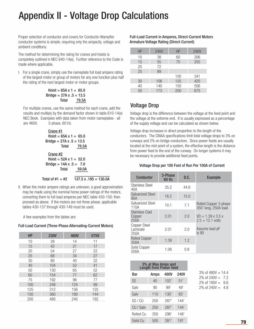
79
Appendix II - Voltage Drop Calculations
Proper selection of conductor and covers for Conductix-Wampfler conductor systems is simple, requiring only the ampacity, voltage and ambient conditions.
The method for determining the rating for cranes and hoists is completely outlined in NEC 640-14(e). Further reference to the Code is made where applicable.
I. For a single crane, simply use the nameplate full load ampere rating of the largest motor or group of motors for any one function plus half the rating of the next largest motor or motor groups.
Hoist = 65A x 1 = 65.0 Bridge = 27A x .5 = 13.5 Total 78.5A
For multiple cranes, use the same method for each crane, add the results and multiply by the demand factor shown in table 610-14(e) NEC Book. Examples with data taken from motor nameplates - all are 460V, 3-phase, 60 Hz.
Crane #1 Hoist = 65A x 1 = 65.0 Bridge = 27A x .5 = 13.5 Total 78.5A
Crane #2 Hoist = 52A x 1 = 52.0 Bridge = 14A x .5 = 7.0 Total 59.0A
Total of #1 + #2 137.5 x .195 = 130.0A
II. When the motor ampere ratings are unknown, a good approximation may be made using the nominal horse power ratings of the motors, converting them to full load amperes per NEC table 430-150; then proceed as above. If the motors are not three-phase, applicable tables 430-137 through 430-149 must be used.
A few examples from the tables are:
Voltage Drop Voltage drop is the difference between the voltage at the feed point and the voltage at the extreme end. It is usually expressed as a percentage of the supply voltage and can be calculated as shown below.
Voltage drop increases in direct proportion to the length of the conductors. The CMAA specifications limit total voltage drops to 3% on runways and 2% on bridge conductors. Since power feeds are usually located at the mid-point of a system, the effective length is the distance from power feed to the end of the runway. On longer systems it may be necessary to provide additional feed points.
HP 230V 460V 575V10 28 14 1115 42 21 1720 54 27 2225 68 34 2730 80 40 3240 104 52 4150 130 65 5260 154 77 6275 192 96 77
100 248 124 99125 312 156 125150 360 180 144200 480 240 192
Full-Load Current (Three-Phase Alternating-Current Motors)
Full-Load Current in Amperes, Direct-Current MotorsArmature Voltage Rating (Direct-Current)
HP 240V HP 240V10 38 60 20615 55 75 25520 7225 89
100 34130 106 125 42540 140 150 50650 173 200 675
Voltage Drop per 100 Feet of Run Per 100A of Current
Conductor 3-Phase60 Hz D.C. Example
Stainless Steel 40A 35.2 44.6
Rolled Copper 3-phase 350’ long, 250A load.
VD = 1.39 x 3.5 x2.5 = 12.1 volts
Assume load pFis 90
Galvanized Steel90A 16.2 15.0
Galvanized Steel110A 10.1 7.1
Stainless CladCopper250A
2.01 2.0
Copper Steel Laminate250A
2.01 2.0
Rolled Copper350A 1.39 1.2
Solid Copper500A 1.08 0.8
3% at Max Amps andLength from Power feed
Bar Amps 480V 240V
SS 40 102’ 51’
Galv 90 99’ 49’
Galv 110 130’ 65’
SS / CU 250 287’ 144’
CU / Galv 250 287’ 144’
Rolled Cu 350 296’ 148’
Solid Cu 500 381’ 191’
3% of 480V = 14.42% of 240V = 7.22% of 180V = 9.62% of 240V = 4.8
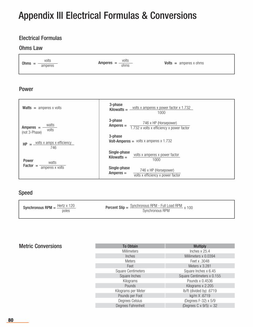
80
Appendix III Electrical Formulas & Conversions
Electrical Formulas
Ohms Law
Power
Speed
volts
amperesOhms = voltsohms
Amperes = Volts = amperes x ohms
wattsvolts
Amperes =(not 3-Phase)
Watts = amperes x volts
volts x amperes x 1.732
volts x amperes x power factor x 1.7321000
3-phaseKilowatts =
3-phaseVolt-Amperes =
Single-phaseKilowatts =
3-phaseAmperes =
Single-phaseAmperes =
wattsamperes x volts
PowerFactor =
volts x amps x efficiency746
HP =
746 x HP (Horsepower)1.732 x volts x efficiency x power factor
volts x amperes x power factor1000
746 x HP (Horsepower)volts x efficiency x power factor
Synchronous RPM = Percent Slip =Hertz x 120poles
Synchronous RPM - Full Load RPMSynchronous RPM
x 100
Metric Conversions To Obtain MultiplyMillimeters Inches x 25.4
Inches Millimeters x 0.0394Meters Feet x .3048Feet Meters x 3.281
Square Centimeters Square Inches x 6.45Square Inches Square Centimeters x 0.155
Kilograms Pounds x 0.4536Pounds Kilograms x 2.205
Kilograms per Meter lb/ft (divided by) .6719Pounds per Foot kg/m X .6719Degrees Celsius (Degrees F-32) x 5/9
Degrees Fahrenheit (Degrees C x 9/5) + 32

81
The technical data and images which appear in this catalog are for informational purposes only. NO WARRANTIES, EXPRESSED OR IMPLIED, INCLUDING WARRANTIES OF MERCHANTABILITY OR FITNESS FOR A PARTICULAR PURPOSE, ARE CREATED BY THE DESCRIPTIONS AND DEPICTIONS OF THE PRODUCTS SHOWN IN THIS CATALOG. Conductix-Wampfler (“seller”) makes no warranty and assumes no liability as to the function of equipment or the operation of systems built according to customer design or of the ability of any of its products to interface, operate or function with any portions of customer systems not provided by Conductix-Wampfler.
Seller agrees to repair or exchange the goods sold hereunder necessitated by reason of defective workmanship, and material discovered and reported to Seller within one year after shipment of such goods to Buyer. Except where the nature of the defect is such that it is appropriate in Seller’s judgement to effect repairs on site, the seller’s obligation hereunder to remedy defects shall be limited to repairing or replacing (at Seller’s option), FOB point of original shipment by Seller, any part returned to Seller at the risk and cost of Buyer. Defective parts replaced by Seller shall become the property of Seller.
Seller shall only be obligated to make such repair or replacement of the goods which have been used by Buyer in service recommended by Seller and altered only as authorized by Seller. Seller is not responsible for defects which arise from improper installation, neglect, or improper use or from normal wear and tear.
Additionally, Seller’s obligation shall be limited by the manufacturer’s warranty (and shall not be further warranted by Seller) for all parts procured from others according to published data, specifications, or performance information not designed by or for Seller.
Seller further agrees to replace, or at Seller’s option to provide a refund of the sales price of any goods that did not conform to applicable specifications or which differ from that agreed to be supplied which non-conformity is discovered and forthwith reported to Seller within thirty (30) days after shipment to Buyer. Seller’s obligation to replace or refund the purchase price for non-conforming goods shall arise once Buyer returns such good FOB point of original shipment by Seller at the risk and cost of Buyer. Goods replaced by Seller shall be come property of Seller.
There is no guarantee or warranty as to anything made or sold by Seller, or any service performed, except as to title and freedom from encumbrances, and except as herein expressly stated and particularly without limiting the foregoing. There is no guarantee or warranty, express or implied, of merchantability or of fitness for any particular purpose or against claim of infringement or the like.
Seller makes no warranty (and assumes no liability) as to function of equipment or operation of systems built to Buyer’s design or of the ability of any goods to interface, operate or function with any portions of Buyer’s system not provided by Seller.
Seller’s liability on any claim; whether in contract (including negligence) or otherwise, for any loss or damage arising out of, connected with, or resulting from the manufacture, sale, delivery, resale, repair, replacement or use of any products or, services shall in no case exceed the price paid for the product or services or any part thereof which give rise to the claim. In no event shall Seller be liable for consequential, special, incidental or other damages, nor shall Seller be liable in respect to personal injury or damage to property on the subject matter hereof unless attributable to gross misconduct of Seller, which shall mean an act of omission by Seller demonstrating reckless disregard of the foreseeable consequences thereof.
Seller is not responsible for incorrect choice of models or where products are used in excess of their rated and recommended capacities and design functions or under abnormal conditions. Seller assumes no liability for loss of time, damage or injuries to property or persons resulting from the use of Seller’s products. Buyer shall hold Seller harmless from all liability, claims, suits and expenses in connection with loss or damage resulting from operation of products or utilization of services, respectively, of Seller and shall defend any suit or action which might arise there from Buyer’s name, provided that Seller shall have the right to elect to defend any such suit or action for the account of Buyer. The foregoing shall be the exclusive remedies of the buyer and all persons and entitles claiming through the Buyer.
Appendix IV Terms, Conditions, and Warranty
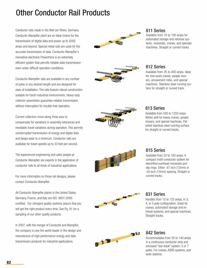
82
Other Conductor Rail Products
Conductor rails made in the Weil am Rhein, Germany
Conductix-Wampfler plant are an ideal choice for the
transmission of digital data and power up to 2000
amps and beyond. Special metal rails are used for the
accurate transmission of data. Conductix-Wampfler's
innovative electronic Powertrans is an extremely
efficient system that permits reliable data transmission
even under difficult operation conditions.
Conductix-Wampfler rails are available in any number
of poles in any desired length and are designed for
ease of installation. The rails feature robust construction
suitable for harsh industrial environments. Heavy-duty
collector assemblies guarantee reliable transmission
without interruption for trouble-free operation.
Current collectors move along three axes to
compensate for variations in assembly tolerances and
inevitable travel variations during operation. This permits
uninterrupted transmission of energy and digital data
and keeps wear to a minimum. Conductor rails are
available for travel speeds up to 33 feet per second.
The experienced engineering and sales people at
Conductix-Wampfler are experts in the application of
conductor rails to all kinds of industrial applications
For more information on these rail designs, please
contact Conductix-Wampfler.
All Conductix-Wampfler plants in the United States,
Germany, France, and Italy are ISO 9001:2000
certified. Our stringent quality systems assure that you
will get the right product every time. See Pg. 91 for a
sampling of our other quality products.
In 2007, with the merger of Conductix and Wampfler,
the company is now the world leader in the design and
manufacture of high performance energy and data
transmission products for industrial applications.
811 SeriesAvailable from 10 to 100 amps for automated storage and retrieval sys-tems, monorails, cranes, and specials machines. Straight or curved tracks.
813 SeriesAvailable from 500 to 1250 amps Works well for heavy cranes, people movers, and special machines. Pat-ented stainless steel running surface for straight or curved tracks.
812 SeriesAvailable from 25 to 400 amps. Ideal for mid-sized cranes, people mov-ers, amusement rides, and special machines. Stainless steel running sur-face for straight or curved track.
815 SeriesAvailable from 32 to 100 amps. A compact multi-conductor system for electrified overhead monorails and slip rings. Either .47 inch (12mm) or .55 inch (14mm) spacing. Straight or curved tracks.
831 SeriesHandles from 10 to 125 amps, in 3, 4, or 5 pole configuration. Great for cranes, automated storage and re-trieval systems, and special machines. Straight tracks.
842 SeriesAccommodates from 35 to 140 amps in a continuous conductor strip and enclosed "box track" system. 5 or 7 poles. For cranes, ASRS systems, and work stations.
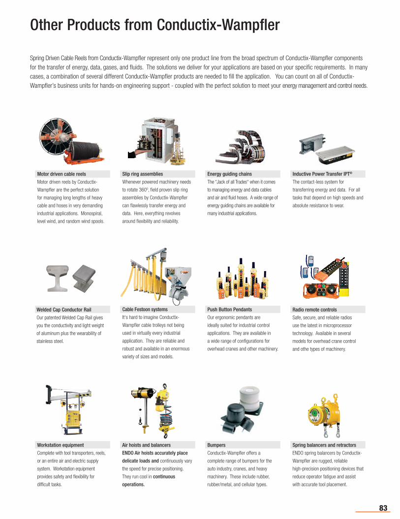
83
Other Products from Conductix-Wampfler
Spring Driven Cable Reels from Conductix-Wampfler represent only one product line from the broad spectrum of Conductix-Wampfler components for the transfer of energy, data, gases, and fluids. The solutions we deliver for your applications are based on your specific requirements. In many cases, a combination of several different Conductix-Wampfler products are needed to fill the application. You can count on all of Conductix-Wampfler’s business units for hands-on engineering support - coupled with the perfect solution to meet your energy management and control needs.
Spring balancers and retractors
ENDO spring balancers by Conductix-
Wampfler are rugged, reliable
high-precision positioning devices that
reduce operator fatigue and assist
with accurate tool placement.
Air hoists and balancers
ENDO Air hoists accurately place
delicate loads and continuously vary
the speed for precise positioning.
They run cool in continuous
operations.
Workstation equipment
Complete with tool transporters, reels,
or an entire air and electric supply
system. Workstation equipment
provides safety and flexibility for
difficult tasks.
Bumpers
Conductix-Wampfler offers a
complete range of bumpers for the
auto industry, cranes, and heavy
machinery. These include rubber,
rubber/metal, and cellular types.
Motor driven cable reels
Motor driven reels by Conductix-
Wampfler are the perfect solution
for managing long lengths of heavy
cable and hoses in very demanding
industrial applications. Monospiral,
level wind, and random wind spools.
Inductive Power Transfer IPT®
The contact-less system for
transferring energy and data. For all
tasks that depend on high speeds and
absolute resistance to wear.
Slip ring assemblies
Whenever powered machinery needs
to rotate 3600, field proven slip ring
assemblies by Conductix-Wampfler
can flawlessly transfer energy and
data. Here, everything revolves
around flexibility and reliability.
Energy guiding chains
The “Jack of all Trades“ when it comes
to managing energy and data cables
and air and fluid hoses. A wide range of
energy guiding chains are available for
many industrial applications.
Push Button Pendants
Our ergonomic pendants are
ideally suited for industrial control
applications. They are available in
a wide range of configurations for
overhead cranes and other machinery.
Radio remote controls
Safe, secure, and reliable radios
use the latest in microprocessor
technology. Available in several
models for overhead crane control
and othe types of machinery.
Cable Festoon systems
It‘s hard to imagine Conductix-
Wampfler cable trolleys not being
used in virtually every industrial
application. They are reliable and
robust and available in an enormous
variety of sizes and models.
Welded Cap Conductor Rail
Our patented Welded Cap Rail gives
you the conductivity and light weight
of aluminum plus the wearability of
stainless steel.
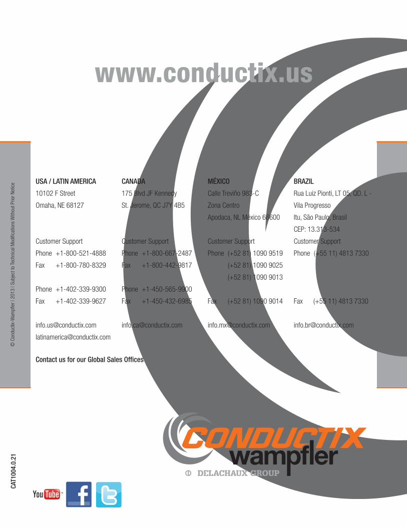
Contact us for our Global Sales Offices
www.conductix.us
CAT1
004.
0.21
USA / LATIN AMERICA
10102 F Street
Omaha, NE 68127
Customer Support
Phone +1-800-521-4888
Fax +1-800-780-8329
Phone +1-402-339-9300
Fax +1-402-339-9627
CANADA
175 Blvd JF Kennedy
St. Jerome, QC J7Y 4B5
Customer Support
Phone +1-800-667-2487
Fax +1-800-442-9817
Phone +1-450-565-9900
Fax +1-450-432-6985
MÉXICO
Calle Treviño 983-C
Zona Centro
Apodaca, NL México 66600
Customer Support
Phone (+52 81) 1090 9519
(+52 81) 1090 9025
(+52 81) 1090 9013
Fax (+52 81) 1090 9014
BRAZIL
Rua Luiz Pionti, LT 05, QD. L -
Vila Progresso
Itu, São Paulo, Brasil
CEP: 13.313-534
Customer Support
Phone (+55 11) 4813 7330
Fax (+55 11) 4813 7330
© C
ondu
ctix-
Wam
pfler
| 20
13 |
Subj
ect t
o Te
chni
cal M
odifi
catio
ns W
ithou
t Prio
r Not
ice