configuration - configworks.com · 7 3. debugging user ... features a dedicated "industry...
TRANSCRIPT

ConfigurationPapers from the Configuration Workshop at IJCAI'05
Dietmar Jannach Alexander Felfernig
Chairs
July 30, 2005
19th International Joint Conference on Artificial Intelligence
University of Edinburgh Edinburgh – Scotland

Organizing Committee
Claire Bagley. Oracle Corporation, USA. Timo Soininen. Helsinki University of Technology, Finland. Markus Stumptner, University of South Australia, Australia.
Program Committee
Michel Aldanondo, Centre de Genie Industriel, Ecole des Mines d'Albi, France. Claire Bagley, Oracle Corporation, USA.
Boi Faltings, Swiss Federal Institute of Technology, Switzerland. Gerhard Friedrich, University Klagenfurt, Austria.
Esther Gelle, ABB Switzerland, Corporate Research, Switzerland.Albert Haag, SAP, Germany.
Ulrich Junker, ILOG S.A., France.Diego Magro, Universita di Torino, Italy.
Michael Koch, Technical University Munich, Germany. Daniel Mailharro, ILOG S.A., France.
Barry O'Sullivan, University College Cork, Ireland. Klas Orsvarn, Tacton System AB, Sweden.
Frank Piller, TUM Research Center Mass Customization & Customer Integration, Germany. Marty Plotkin, Oracle Corporation, USA.
Timo Soininen, Helsinki University of Technology, Finland.Pietro Torasso, Universita di Torino, Italy.
Markus Stumptner, Advanced Computing Research Center, Australia. Markus Zanker, University Klagenfurt, Austria.

Contents
1. A Decision Tree Learning and Constraint Satisfaction Hybrid for Interactive Problem Solving Barry O’Sullivan and Alex Ferguson and Eugene C. Freuder...................... p. 1
2. Linear Functions for Interactive Configuration Using Join Matching and CSP Tree Decomposition Sathiamoorthy Subbarayan, Henrik Reif Andersen....................................... p. 7
3. Debugging User Interface Descriptions of Knowledge-based Recommenders Alexander Felfernig, Shchekotykhin Kostyantyn.......................................... p. 13
4. A Conceptual Model for Configurable Services Mikko Heiskala, Juha Tiihonen, and Timo Soininen.................................... p. 19
5. Modeling Multiple System Families Esther Gelle.................................................................................................. p. 25
6. Design Space Exploration Using Constraint Satisfaction Noel Titus, Karthik Ramani......................................................................... p. 31
7. Configuring Loopholes: Interactive Consistency Maintenance of Business Rules Markus Stumptner, Michael Schrefl............................................................ p. 37
8. Interactive Configuration and Evaluation of a Heat Treatment Operation M. Aldanondo, E. Vareilles, K. Hadj-Hamou and Paul Gaborit................ p. 40
9. STAR-IT: a Tool to Build STAR Applications Diego Magro............................................................................................... p. 46
10. Kumbang Configurator–A Configuration Tool for Software Product Families V. Myllärniemi and T. Asikainen and T. Männistö and T. Soininen........... p. 51
11. PLM-integrated Configurators for Machine and Plant Construction Philipp Ackermann..................................................................................... p. 57
12. Co-Configuration of Products and On-Line Service Manuals Carsten Sinz and Wolfgang Küchlin.......................................................... p. 60
13. Reconfiguration – A Problem in Search of Solutions Peter Manhart............................................................................................ p. 64
14. “Dealing” with Configurable Products in the SAP Business Suite Albert Haag............................................................................................... p. 68
15. Configurators in innovative or standardized business processes Gerhard Fleischanderl.............................................................................. p. 72
16. MCml2Jiri Vyskocil, Martin Trcka, Libor Denner, Petr Svab.............................. p. 73
17. Tacton Configurator – Research directions Klas Orsvarn............................................................................................. p. 75

Preface
Configuration problems have always been subject of interest for the application and the development of advanced AI-based techniques. In particular, the great variety and the complexity of configurable product models both require powerful knowledge-representation formalisms while on the other hand efficient reasoning methods are needed to provide intelligent interactive behavior including solution search, satisfaction of user preferences, personalization and optimization.
Driven by academic and industrial interest, the IJCAI'05 Configuration Workshop now continues a series of successful workshops that started at the AAAI'96 Fall Symposium and continued on IJCAI, AAAI, and ECAI since 1999. The selection of papers of this year's workshop demonstrates the wide range of applicable AI techniques in the domain including contributions both on algorithms, search performance and user interaction, as well as on novel approaches related to knowledge-representation and product modeling.
Beside the research aspect, this year's workshop also has a strong emphasis on real-world configuration problems, tools, and applications. The working notes therefore also include a selected set of short papers and position statements from industry describing experience reports, problem statements, and advanced configuration tools. In addition, the workshop also features a dedicated "industry session" and a discussion panel with participants from major configurator vendors as well as representatives from companies with long-term experiences in deploying configuration applications in different domains. As such, this year's event aims at providing a stimulating environment for knowledge-exchange among academia and industry and thus building a solid basis for further developments in the field.
Dietmar Jannach Alexander Felfernig
University Klagenfurt, Austria

A Decision Tree Learning and Constraint Satisfaction Hybridfor Interactive Problem Solving�
Barry O’Sullivan and Alex Ferguson and Eugene C. FreuderCork Constraint Computation Centre
Department of Computer Science, University College Cork, Ireland{b.osullivan|a.ferguson|e.freuder}@4c.ucc.ie
AbstractIn this paper we present an approach to using de-cision tree learning as a basis for improving searchperformance for real-world constraint satisfactionproblems. The problem used to evaluate the ap-proach is a large real-world configuration bench-mark from the automotive industry.
1 IntroductionThe traditional focus of the constraint satisfaction commu-nity is solving a CSP instance once, and once only. For exam-ple, finding a solution to a set of layout constraints, a plan-ning problem, a scheduling problem or timetabling problem.However, in many real-world domains CSPs are solved manytimes over. For example, a CSP may represent a configurationproblem. Since different users will seek different configura-tions, the same instance of the configuration CSP is solvedrepeatedly, but the users’ choices change each time. In such ascenario users make decisions by interactively assigning val-ues to some subset of the variables of the underlying CSP,representing a set of choices or desires. The task of a systemreasoning about such a problem, or configurator, is to presenta solution that satisfies the set of choices the user has made,or to report that none exists.
In real-world application contexts, such as the one outlinedabove, the underlying CSP often exhibits a structured solu-tion space. For example, there may be many solutions to theproblem that are different only in terms of a small number ofassignments. Specifically, many real-world problems exhibitsome form of interchangeability amongst values [Freuder,1991]; i.e. we may be free to change one assignment in asolution, holding the others fixed, and still have a solution. Insuch cases machine learning techniques can be employed totake advantage of this structure in order to enhance the per-formance of the constraint solver used to solve the CSP. It isthis observation that underpins the work we present here.
In many domains, such as product configuration, users arebetter able to specify their requirements by critiquing a solu-tion. For example, a user might specify a car with a sunroof� This work has received support from Enterprise Ireland (Grant
SC/2002/289) and Science Foundation Ireland under Grant No.03/CE3/I405, as part of the Centre for TelecommunicationsValue-Chain-Driven Research (CTVR), and Grant 00/PI.1/C075.
and air-conditioning, but having been presented with a carthat met these requirements but having only two seats, realizethat it was important, perhaps more important, to have fiveseats. Note that the user model used in this work in one inwhich the system takes the initiative in deciding which vari-ables the user should make decisions about, but if this is re-garded as a limitation it should only be seen as a limitation infinding the first solution. The user will be free to critique thissolution on the basis of his/her preferences in a subsequentsolution critiquing phase [Pu and Faltings, 2004]. Our objec-tive is to help a user find an initial solution that satisfies someof his/her desires as quickly as possible so that the critiquingphase can begin.
The approach we present combines decision tree learn-ing [Quinlan, 1986] with constraint satisfaction techniques.We induce a decision tree from a set of positive examples(solutions to the CSP) and negative examples (non-solutionsto the CSP). Positive examples can be found either by searchor, as is more likely in many real-world contexts such as con-figuration, from a catalogue or brochure containing examplesof the solutions that are available. It is trivial to randomlygenerate a set of negative examples. The decision tree acts asa first step in a two step solving process, specifying subprob-lems of the CSP to be searched using standard techniques. Theimprovements that can be obtained are often considerable.
We propose a number of different ways to post-process thedecision tree that have the potential to dramatically reducethe search effort required to find a solution. Often search isunnecessary, since it can be proven by the decision tree alonethat a solution exists or does not exist. In terms of the over-all result, we demonstrate that the approach yields significantreductions in search effort on a large real-world configurationbenchmark when compared with a good constraint solver.Furthermore, we show that the reduction in search cost comesat negligible space cost.
We also present a surprising result: using decision treesinduced from training sets of increasing size, the accu-racy associated with classifying unseen solutions and non-solutions quickly becomes close to perfect. This is unexpect-edly favourable, given that the decision trees we induce re-main very small.
This paper builds on earlier work on this topic [O’Sullivanet al., 2004]. This earlier work proposed using decision treesfor improving upon the effort required to find a solution to
1/75
a CSP. In particular, the earlier work demonstrated how prob-lems with high levels of interchangeability could benefit fromsuch an approach. In this paper a number of new results arepresented. Firstly, we demonstrate the technique on a largereal-world configuration problem. Secondly, we propose thenotion of a lax query. Thirdly, we demonstrate that the clas-sification accuracy of decision trees built for the real-worldproblem studied here is extremely high while the size of suchdecision trees is very small.
The remainder of this paper is organized as follows. Sec-tion 2 presents the details of our approach. In Section 3 wepresent results from an empirical evaluation carried out ona large real-world configuration problem. In Section 4 webriefly review the relevant related literature, demonstratingthe novelty of the approach proposed here. In Section 5 anumber of directions for future work are discussed and someconcluding remarks are made.
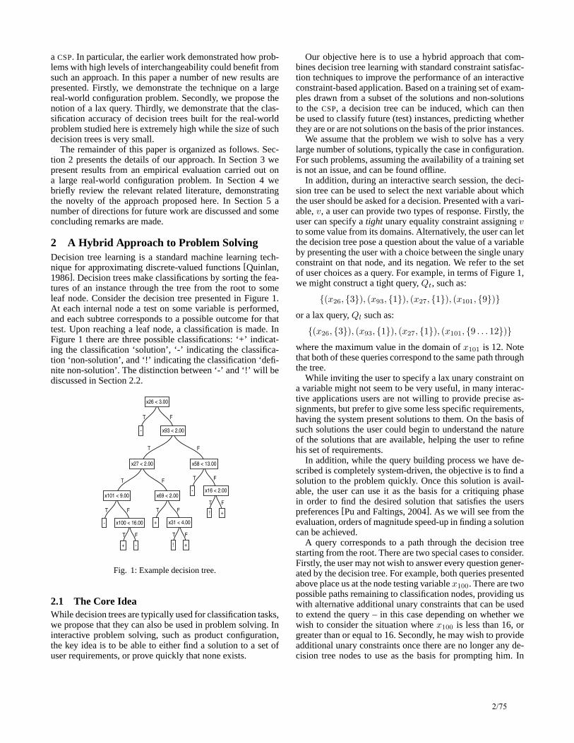
2 A Hybrid Approach to Problem SolvingDecision tree learning is a standard machine learning tech-nique for approximating discrete-valued functions [Quinlan,1986]. Decision trees make classifications by sorting the fea-tures of an instance through the tree from the root to someleaf node. Consider the decision tree presented in Figure 1.At each internal node a test on some variable is performed,and each subtree corresponds to a possible outcome for thattest. Upon reaching a leaf node, a classification is made. InFigure 1 there are three possible classifications: ‘+’ indicat-ing the classification ‘solution’, ‘-’ indicating the classifica-tion ‘non-solution’, and ‘!’ indicating the classification ‘defi-nite non-solution’. The distinction between ‘-’ and ‘!’ will bediscussed in Section 2.2.
T
-
F
T
T
T
-
F
T
+
F
-
x100 < 16.00
x101 < 9.00
F
T
+
F
T
!
F
+
x31 < 4.00
x69 < 2.00
x27 < 2.00
F
T
-
F
T
!
F
+
x16 < 2.00
x58 < 13.00
x93 < 2.00
x26 < 3.00
Fig. 1: Example decision tree.
2.1 The Core IdeaWhile decision trees are typically used for classification tasks,we propose that they can also be used in problem solving. Ininteractive problem solving, such as product configuration,the key idea is to be able to either find a solution to a set ofuser requirements, or prove quickly that none exists.
Our objective here is to use a hybrid approach that com-bines decision tree learning with standard constraint satisfac-tion techniques to improve the performance of an interactiveconstraint-based application. Based on a training set of exam-ples drawn from a subset of the solutions and non-solutionsto the CSP, a decision tree can be induced, which can thenbe used to classify future (test) instances, predicting whetherthey are or are not solutions on the basis of the prior instances.
We assume that the problem we wish to solve has a verylarge number of solutions, typically the case in configuration.For such problems, assuming the availability of a training setis not an issue, and can be found offline.
In addition, during an interactive search session, the deci-sion tree can be used to select the next variable about whichthe user should be asked for a decision. Presented with a vari-able, v, a user can provide two types of response. Firstly, theuser can specify a tight unary equality constraint assigning vto some value from its domains. Alternatively, the user can letthe decision tree pose a question about the value of a variableby presenting the user with a choice between the single unaryconstraint on that node, and its negation. We refer to the setof user choices as a query. For example, in terms of Figure 1,we might construct a tight query, Qt, such as:
{(x26, {3}), (x93, {1}), (x27, {1}), (x101, {9})}or a lax query, Ql such as:
{(x26, {3}), (x93, {1}), (x27, {1}), (x101, {9 . . . 12})}where the maximum value in the domain of x101 is 12. Notethat both of these queries correspond to the same path throughthe tree.
While inviting the user to specify a lax unary constraint ona variable might not seem to be very useful, in many interac-tive applications users are not willing to provide precise as-signments, but prefer to give some less specific requirements,having the system present solutions to them. On the basis ofsuch solutions the user could begin to understand the natureof the solutions that are available, helping the user to refinehis set of requirements.
In addition, while the query building process we have de-scribed is completely system-driven, the objective is to find asolution to the problem quickly. Once this solution is avail-able, the user can use it as the basis for a critiquing phasein order to find the desired solution that satisfies the userspreferences [Pu and Faltings, 2004]. As we will see from theevaluation, orders of magnitude speed-up in finding a solutioncan be achieved.
A query corresponds to a path through the decision treestarting from the root. There are two special cases to consider.Firstly, the user may not wish to answer every question gener-ated by the decision tree. For example, both queries presentedabove place us at the node testing variable x100. There are twopossible paths remaining to classification nodes, providing uswith alternative additional unary constraints that can be usedto extend the query – in this case depending on whether wewish to consider the situation where x100 is less than 16, orgreater than or equal to 16. Secondly, he may wish to provideadditional unary constraints once there are no longer any de-cision tree nodes to use as the basis for prompting him. In
2/75

this case, the user’s query will have reached a leaf node andadditional unary constraints are presented. For example, thequery {(x26, {1}), (x40, {1})} is classified as negative by thetree on the basis of the unary constraint on variable x26, how-ever we also have an additional constraint on variable x40.
Thus, in general, having followed a path through the deci-sion tree, we obtain a set of leaf nodes, each associated with anumber of constraints, and a positive/negative classification.At this point we can rely on constraint satisfaction to eitherfind a solution satisfying the user’s query constraints, or ver-ify that none exists. This is done by solving, in turn, the sub-problem associated with each positive classification, stoppingas soon as we find one that is soluble; if we find none, thenwe repeat the process on the sub-problems associated with thenegative classifications. This last step is necessary to achieveaccurate results, as a presumptively negative region of thesolution space may not in fact be solution-free, but simplylack a solution in the training set. Thus, in the case of thelonger query, Qt, presented earlier, we will first solve the sin-gle subproblem corresponding to the extension of the query:Qt ∪ {x100 < 16} (classified as positive) and subsequently,if necessary, that corresponding to: Qt ∪ {x100 ≥ 16}.
Therefore, having processed a query, we get advice fromthe decision tree that indicates whether or not a solution ex-ists and a number of sub-problems that can be searched toguarantee completeness of the approach.
2.2 EnhancementsWe have found that using a decision tree that has been in-duced directly from the training set does not improve overimmediate search on the user’s query. Generally we simplyend up solving essentially the same problem, or several sub-problems corresponding to a partition thereof. However, wecan identify two distinct ways of enhancing the potential per-formance improvement possible in decision tree lookup.
Firstly, once the decision tree has been induced, wecan analyze each negative node to determine if there isany extension of that node’s path that leads to a solu-tion in the problem at large. If there is not, we can labelthis node as a definite negative classification. For ex-ample, in Figure 1, the path corresponding to the query{(x26, {3}), (x93, {1}), (x27, {2}), (x69, {2}), (x31, {1})},has no solutions, and thus we can annotate the correspondingleaf node with a ‘!’ rather than a ‘-’. The consequencesof this are that we can entirely eliminate such nodes fromconsideration when we encounter them while processinga query, and that if only one such node is found, we mayimmediately terminate. If the sub-problem is in fact soluble,we leave the node’s annotation unchanged, and treat itexactly as we previously treated all negatively classifiednodes, i.e. this node will still have to be searched if it isencountered. We will refer to trees that have be processed inthis way as being purified to reflect the fact that they identifyall definite negative classifications, i.e. those that are purewith respect to the whole solution space, rather than simply agiven training set.
Secondly, associated with each positive node, we can ex-emplify the corresponding partial solution by storing onecomplete solution which has the path to that node as a pre-
fix. The consequence of this is that if a user’s query does notextend past that classification node we can immediately stopat that point, saving us from performing any search. On theother hand, if the user’s query does extend past a particularclassification node, but the user’s remaining constraints areconsistent with the solution associated with that leaf, we canstop, again saving us from performing any search. We will re-fer to trees that have be processed in this way as being exem-plified. We can combine both enhancements to form a purifiedexemplified decision tree.
3 Experiments
We ran experiments using the Renault Megane Configurationbenchmark [Amilhastre et al., 2002], a large real-world con-figuration problem. The variables represent various optionssuch as engine type, interior options, etc. The problem con-sists of 101 variables, domain size varies from 1 to 43, andthere are 113 constraints, many of them non-binary. The num-ber of solutions to the problem is over 1.4 × 10¹².
The constraint solver we used in our experiments is a gen-eralized forward checker, that propagates k-ary constraintswhen k−1 variables are instantiated. We used minimum ratioof domain over forward degree as a variable ordering heuris-tic, and lexicographically chose values from within each do-main. In order to improve solution time, we added the bi-nary projections of all non-binary constraints in the prob-lem, giving us 422 constraints in total. Adding these binaryprojections improves the performance of generalized forwardchecking by several orders of magnitude in constraint checks.
This solver provided us with a baseline for comparing theperformance of the decision tree-based hybrid against tradi-tional direct search; and furthermore, having identified sub-problems from the decision tree, gives a facility to solvethose. Therefore to some extent, we can remove some pos-sible bias from any comparison by using the same solver ineach case, thus getting a relatively ‘like with like’ compari-son.
Two different experiments were conducted. Firstly, westudied the classification accuracy of the decision trees we in-duced directly from the training set (Section 3.1). Secondly,we compared the performance of the decision tree-based hy-brid against the base-line constraint solver (Section 3.2).
We generated decision trees based on different sized train-ing sets comprising a number of exemplars of both ‘classes’to be discriminated: solutions to the CSP (positive examples),and non-solutions — that is, fully instantiated tuples that arenot solutions to the CSP. We have chosen, somewhat arbitrar-ily, to use throughout three times as many negative examplesas positive ones. In partial justification we note that solutionsare both less heavily represented in the space, and are morecostly to obtain.
Solutions were generated by fixing a variable order, usingwhich a set of feasible partial solutions (prefixes) of increas-ing length were calculated, until the cardinality of this prefixset exceeded the size of the desired solutions set. The desirednumber of prefixes were then selected and extended randomlyto solutions.
3/75
Obtaining the negative examples is straightforward, as theyrepresent the considerable majority of the solution space, andcan, thus, easily be generated equiprobably at random. Weconstructed decision trees using ITI [Utgoff et al., 1997].Trees were built using the ‘quick build’ option, i.e. using the-f flag of the ITI program.
We conducted each experiment with decision trees inducedfrom training sets containing 10, 20, 50, 100, 200, 500, 1000,2000, 5000 and 10000 positive examples, in turn.
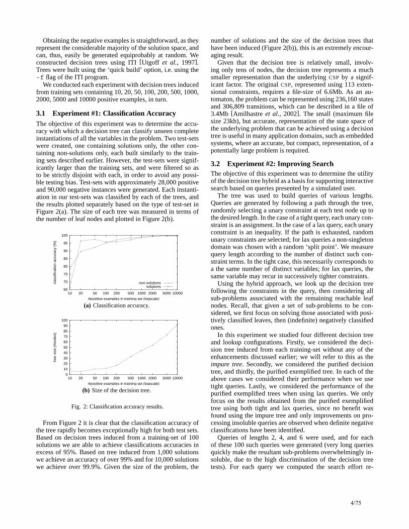
3.1 Experiment #1: Classification AccuracyThe objective of this experiment was to determine the accu-racy with which a decision tree can classify unseen completeinstantiations of all the variables in the problem. Two test-setswere created, one containing solutions only, the other con-taining non-solutions only, each built similarly to the train-ing sets described earlier. However, the test-sets were signif-icantly larger than the training sets, and were filtered so asto be strictly disjoint with each, in order to avoid any possi-ble testing bias. Test-sets with approximately 28,000 positiveand 90,000 negative instances were generated. Each instanti-ation in our test-sets was classified by each of the trees, andthe results plotted separately based on the type of test-set inFigure 2(a). The size of each tree was measured in terms ofthe number of leaf nodes and plotted in Figure 2(b).
65
70
75
80
85
90
95
100
10000500020001000500200100502010
clas
sific
atio
n ac
cura
cy (
%)
#positive examples in training set (logscale)
non-solutionssolutions
(a) Classification accuracy.
0
10
20
30
40
50
60
70
80
90
100
10000500020001000500200100502010
tree
siz
e (#
node
s)
#positive examples in training set (logscale)
(b) Size of the decision tree.
Fig. 2: Classification accuracy results.
From Figure 2 it is clear that the classification accuracy ofthe tree rapidly becomes exceptionally high for both test sets.Based on decision trees induced from a training-set of 100solutions we are able to achieve classifications accuracies inexcess of 95%. Based on tree induced from 1,000 solutionswe achieve an accuracy of over 99% and for 10,000 solutionswe achieve over 99.9%. Given the size of the problem, the
number of solutions and the size of the decision trees thathave been induced (Figure 2(b)), this is an extremely encour-aging result.
Given that the decision tree is relatively small, involv-ing only tens of nodes, the decision tree represents a muchsmaller representation than the underlying CSP by a signif-icant factor. The original CSP, represented using 113 exten-sional constraints, requires a file-size of 6.6Mb. As an au-tomaton, the problem can be represented using 236,160 statesand 306,809 transitions, which can be described in a file of3.4Mb [Amilhastre et al., 2002]. The small (maximum filesize 23kb), but accurate, representation of the state space ofthe underlying problem that can be achieved using a decisiontree is useful in many application domains, such as embeddedsystems, where an accurate, but compact, representation, of apotentially large problem is required.
3.2 Experiment #2: Improving SearchThe objective of this experiment was to determine the utilityof the decision tree hybrid as a basis for supporting interactivesearch based on queries presented by a simulated user.
The tree was used to build queries of various lengths.Queries are generated by following a path through the tree,randomly selecting a unary constraint at each test node up tothe desired length. In the case of a tight query, each unary con-straint is an assignment. In the case of a lax query, each unaryconstraint is an inequality. If the path is exhausted, randomunary constraints are selected; for lax queries a non-singletondomain was chosen with a random ‘split point’. We measurequery length according to the number of distinct such con-straint terms. In the tight case, this necessarily corresponds toa the same number of distinct variables; for lax queries, thesame variable may recur in successively tighter constraints.
Using the hybrid approach, we look up the decision treefollowing the constraints in the query, then considering allsub-problems associated with the remaining reachable leafnodes. Recall, that given a set of sub-problems to be con-sidered, we first focus on solving those associated with posi-tively classified leaves, then (indefinite) negatively classifiedones.
In this experiment we studied four different decision treeand lookup configurations. Firstly, we considered the deci-sion tree induced from each training-set without any of theenhancements discussed earlier; we will refer to this as theimpure tree. Secondly, we considered the purified decisiontree, and thirdly, the purified exemplified tree. In each of theabove cases we considered their performance when we usetight queries. Lastly, we considered the performance of thepurified exemplified trees when using lax queries. We onlyfocus on the results obtained from the purified exemplifiedtree using both tight and lax queries, since no benefit wasfound using the impure tree and only improvements on pro-cessing insoluble queries are observed when definite negativeclassifications have been identified.
Queries of lengths 2, 4, and 6 were used, and for eachof these 100 such queries were generated (very long queriesquickly make the resultant sub-problems overwhelmingly in-soluble, due to the high discrimination of the decision treetests). For each query we computed the search effort re-
4/75

0.1
1
10
100
1000
10000
10000500020001000500200100
fact
or o
f im
prov
emen
t
#positive examples in training set (logscale)
soluble, q=2soluble, q=4soluble, q=6
insoluble, q=2insoluble, q=4insoluble, q=6
(a) Purified exemplified tree (Tight queries).
0.1
1
10
100
1000
10000
10000500020001000500200100
fact
or o
f im
prov
emen
t
#positive examples in training set (logscale)
soluble, q=2soluble, q=4soluble, q=6
insoluble, q=2insoluble, q=4insoluble, q=6
(b) Purified exemplified tree (Lax queries).
0 10 20 30 40 50 60
(q=
6,10
^5)
(q=
6,10
^4)
(q=
6,10
^3)
(q=
6,10
^2)
(q=
6,10
^1)
(q=
6,-1
0^1)
(q=
4,10
^5)
(q=
4,10
^4)
(q=
4,10
^3)
(q=
4,10
^2)
(q=
4,10
^1)
(q=
4,-1
0^1)
(q=
2,10
^5)
(q=
2,10
^4)
(q=
2,10
^4)
(q=
2,10
^2)
(q=
2,10
^1)
(q=
2,-1
0^1)
freq
uenc
y
(query size, order of improvement) pairs
lax soluble queries (decision tree built from 1000 positive seeds)
(c) Detailed improvement results for soluble queries.
0 10 20 30 40 50 60
(q=
6,10
^5)
(q=
6,10
^4)
(q=
6,10
^3)
(q=
6,10
^2)
(q=
6,10
^1)
(q=
6,-1
0^1)
(q=
4,10
^5)
(q=
4,10
^4)
(q=
4,10
^3)
(q=
4,10
^2)
(q=
4,10
^1)
(q=
4,-1
0^1)
(q=
2,10
^5)
(q=
2,10
^4)
(q=
2,10
^4)
(q=
2,10
^2)
(q=
2,10
^1)
(q=
2,-1
0^1)
freq
uenc
y
(query size, order of improvement) pairs
lax insoluble queries (decision tree built from 1000 positive seeds)
(d) Detailed improvement results for insoluble queries.
Fig. 3: Results for constraint satisfaction.
quired by the reference solver to decide the user’s query.This was compared with the search effort required by the hy-brid decision-tree-based approach. Search effort is measuredin terms of constraint checks, plus decision tree checks forthe hybrid approach. We compute the improvement factor ofthe hybrid approach over the reference solver using ccs/cch,where ccs is the number of constraint checks required by thereference solver, and cch is the sum of the number of con-straint checks and decision tree checks required by the hybridapproach.
In Figure 3, we show the median improvements associatedwith processing both soluble and insoluble queries separatelyusing tight queries (Figure 3(a)) and lax queries (Figure 3(b))on the pure exemplified decision tree.
It is clear that we obtain improvements for both soluble andinsoluble queries. Once all definite negative classificationshave been identified, we obtain at least two orders of mag-nitude for the larger trees when processing insoluble queries(Figure 3(a) and 3(b)). This improvement is essentially due toour not having to resort to any search at all on many insolublequeries, i.e. the decision tree is sufficient to determine insolu-bility, while the reference solver must perform some work toreach the same conclusion.
The most dramatic improvement can be observed with laxqueries. In the case of soluble lax queries we can find that im-provements of a factor of 300 are possible, while performancefor insoluble queries is further improved by a marked amount.
This is to be expected, as such queries constrain the originalproblem much less, and non-singleton unary constraints arenot propagated as much as the assignments of tight queriesby the reference solver. Therefore search is more expensivein such cases, and thus there is more room for improvement.
In Figures 3(c) and 3(d) we present, in more detail, theimprovements achieved when processing lax queries on thepure exemplified tree, built from a training-set containing1000 solutions, when processing both soluble and insolublequeries, respectively. Each graph shows the number of timeswe achieve an improvement of a given magnitude for differ-ent query sizes. Note that we rarely observe disimprovementsof an order of magnitude (−10), but often observe improve-ments up to 104. These plots show the results of processing100 queries of each size, therefore the frequencies for a givenquery size in both graphs will sum to 100. Taking a look at thelevel of individual queries (Figure 3(c) and 3(d)) we can seethat there is a much more systematic improvement associatedwith processing insoluble queries.
We can see that using our hybrid approach never has a largenegative impact on performance; Figures 3(c) and 3(d) showonly a tiny negative impact for query sizes of length 6 in eachcase. This impact is not sufficient to affect the median im-provement factor results presented in Figures 3(a) and 3(b).However, the hybrid approach can dramatically improve per-formance by orders of magnitude, particularly if users buildlax queries. Such queries may be more likely to be used by
5/75

users who are not very familiar with the solution space, andwho may be more confident giving less committal responsesto the configurator. In such cases, the decision tree methodexcels.
4 Related WorkOne of the significant challenges of constraint satisfactiontechniques is the amount of search effort that may be requiredto solve a problem. In the general case, finding a solution to aCSP is NP-complete. To address this, many techniques havebeen developed that try to minimize or avoid costly back-tracking during search.
It has long been known that tree-structured constraint prob-lems can be solved without backtracking [Freuder, 1982].This result has been extended to more general constraint net-works also [Freuder, 1990; Dechter and Pearl, 1987]. How-ever, these latter approaches may be impractical due to theirexponential worst-case space complexity.
Recent work has combined automata theory and constraintsatisfaction as a basis for supporting interactive configura-tion [Amilhastre et al., 2002]. That approach essentially com-piles a CSP into a form that can be used to answer particu-lar questions without backtracking. Again, the disadvantagehere is that the size of the automaton can grow exponentially,depending on the properties of the constraint problem beingconsidered.
The notion of a general purpose backtrack-free represen-tation for a CSP has been studied in the context of configu-ration [Beck et al., 2004]. This approach uses a fixed vari-able ordering to preprocess a CSP. By working in reversethrough the variable ordering, values that could cause a back-track are removed, so that backtracking never occurs when theCSP is being solved ‘online’. The transformed CSP is called abacktrack-free representation (BFR). Of course, when valuesare removed, so may be solutions. So in this approach the im-provements in search efficiency come at the expense of lostsolutions. While this is not acceptable in many domains, it isreasonable in some others where a solution needs to be foundvery quickly.
An alternative approach to improving the performance ofsearch is the notion of nogood recording [Schiex and Ver-faillie, 1994]. Nogoods are justifications of why particularinstantiations of variables are inconsistent. By recording no-goods during search, backtracking can be minimized by ex-ploiting this knowledge as search continues. However, in itsgeneral form this approach also requires exponential space,in the worst-case.
In this paper an approach to improving the search for a so-lution has been developed by relying on the inherent structurein the problem as a basis for learning how to characterize so-lutions. We can compare the decision tree as a data structureto the principle underlying automaton-based approaches dis-cussed above. The advantage of this approach is that we avoidthe risk of incurring an exponential space cost, since we canbound the input to limit the size of the decision tree. Also,the decision tree can be seen as having some of the advan-tages of BFRs, specifically, an improvement in search cost,but without the penalty of solution loss.
5 Conclusions and Future WorkIn this paper we have presented a hybrid approach to support-ing interactive constraint satisfaction. The hybrid combinesboth decision tree learning with constraint satisfaction tech-niques. Our results demonstrate that machine learning tech-niques provide a very useful basis for improving the per-formance of constraint satisfaction techniques for interactiveproblem solving.
There are some interesting issues to be studied here. In par-ticular, we have seen how the classification accuracy of rel-atively small decision trees is surprisingly high. This raisesthe following question: what is special, if anything, about thevariables and the values referenced in the decision trees? Itwould be interesting to study this issue in greater detail.
Finally, while the user model currently used here isquite restrictive, being completely system-driven, we plan onstudying ways to relax this restriction so user preferences canalso be taken into account when finding an initial solution.
References[Amilhastre et al., 2002] J. Amilhastre, H. Fargier, and P. Marguis.
Consistency restoration and explanations in dynamic csps – ap-plication to configuration. Artificial Intelligence, 135:199–234,2002.
[Beck et al., 2004] J.C. Beck, T. Carchrae, E. C. Freuder, andG. Ringwelski. Backtrack-free search for real-time constraint sat-isfaction. In CP, LNCS 3258, pages 92–106, 2004.
[Dechter and Pearl, 1987] R. Dechter and J. Pearl. Network-basedheuristics for constraint satisfaction problems. Artificial Intelli-gence, 34(1):1–38, 1987.
[Freuder, 1982] E.C. Freuder. A sufficient condition for backtrack-free search. Journal of the ACM, 29(1):24–32, 1982.
[Freuder, 1990] E.C. Freuder. Complexity of k-tree-structured con-straint satisfaction problems. In Proceedings of AAAI-90, pages4–9, 1990.
[Freuder, 1991] E.C. Freuder. Eliminating interchangeable valuesin constraint satisfaction problems. In Proceedings of the AAAI,pages 227–233, 1991.
[O’Sullivan et al., 2004] B. O’Sullivan, A. Ferguson, and E.C.Freuder. Boosting constraint satisfaction using decision trees. InProceedings of ICTAI-2004, pages 646–651, 2004.
[Pu and Faltings, 2004] P. Pu and B. Faltings. Decision tradeoff us-ing example-critiquing and constraint programming. Constraints,9(4):289–310, 2004.
[Quinlan, 1986] J.R. Quinlan. Induction of decision trees. MachineLearning, 1(1):81–106, 1986.
[Schiex and Verfaillie, 1994] T. Schiex and G. Verfaillie. Nogoodrecording for static and dynamic constraint satisfaction probles.Journal on Artificial Intelligence Tools, 3(2):187–207, 1994.
[Utgoff et al., 1997] P.E. Utgoff, N.C. Berkman, and J.A. Clouse.Decision tree induction based on efficient tree restructuring. Ma-chine Learning, 29:5–44, 1997.
6/75

Linear Functions for Interactive Configuration Using Join Matching and CSPTree Decomposition
Sathiamoorthy Subbarayan, Henrik Reif AndersenDepartment of Innovation, IT University of Copenhagen
Denmark
AbstractQuick responses are required for interactive con-figuration. For this an ideal interactive configura-tor needs to provide the functionalities required forinteractive configuration with at most linear timecomplexity. In this paper, we present such a datastructure called Join Matched CSP (JMCSP). Whena JMCSP is used to represent a configuration prob-lem, the functionalities required for interactive con-figuration can be obtained with linear time com-plexity.Unlike the tree-of-BDDs [Subbarayan, 2005],the JMCSPs while taking advantage of tree-decomposition also provide linear configurationfunctions. Although obtaining a JMCSP is expo-nential in the tree-width of the input configurationproblem, due to tree-like hierarchical nature of con-figuration problems, this is typically feasible. Wepresent the JMCSP compilation process along withthe linear interactive configuration functions on it.The linear functionalities provided by the JMCSPsinclude computation of all minimum explanations.
1 IntroductionThe complexity of made-to-order products keeps increas-ing. Examples of such products include personal computers,bikes, and power-backup systems. Such products will be rep-resented in the form of a product model. A product modelwill list the parameters (variables) defining the product, theirpossible values and the rules by which those parameter val-ues can be chosen. A product model implicitly represents allvalid configurations of a product, and it can be viewed as aConstraint Satisfaction Problem (CSP), where the solutionsto the CSP are equivalent to valid configurations of the corre-sponding product model.
The increase in the complexity of made-to-order productsrises the need for efficient decision support systems to con-figure a product based on the requirements posed by the cus-tomer. Such decision support systems are called configura-tors. Configurators read a product model which representsall valid configurations of the product and guides the user inchoosing one among the valid configurations as close as pos-sible to his requirements. An interactive configurator takes
a product model as input and interactively helps the user tochoose his preferred values for the parameters in the productmodel, one-by-one.
The interactive configurator needs to be complete andbacktrack-free. Complete means that all valid configurationsneed to be configurable using the configurator. Backtrack-free means that the configurator should not allow the user tochoose a value for a parameter in the product model whichwould eventually lead him to no valid configurations. To en-sure backtrack-freeness, the interactive configurator needs toprune away values from the possible values of parameters inthe product model as and when those values will not lead toany valid configuration. In addition, the interactive configu-rator needs to give responses in a short period of time. Exam-ples for commercial interactive configurators include ConfigitDeveloper [Configit-Software, 2005] and Array Configura-tor [Array-Technology, 2005].
The Binary Decision Diagram (BDD) [Bryant, 1986] basedsymbolic CSP compilation technique [Hadzic et al., 2004;Subbarayan et al., 2004] can be used to compile all solu-tions of a configuration problem into a single (monolithic)BDD. Once a BDD is obtained, the functions required for in-teractive configuration can be efficiently implemented. Theproblem with such approaches is that they do not exploitthe fact that configuration problems are specified in hierar-chies. Due to this the BDD obtained after compilation couldbe unnecessarily large. Such hierarchies are closer to treesin shape. The tree-of-BDDs approach: a combination of theBDD-based compilation technique and a CSP decompositiontechnique for efficient compilation of all solutions was pre-sented in [Subbarayan, 2005]. The tree-of-BDDs scheme ex-ploited the tree-like nature of configuration problems. Theadvantage of monolithic-BDD is that it can provide linearfunctions for interactive configuration. The advantage of tree-of-BDDs is that they need very small space to store, whencompared with that of the monolithic-BDD. But, at the costof having costly functions for interactive configuration. Theresults in [Subbarayan, 2005] have shown that, for functional-ities like minimum explanation generation, the tree-of-BDDscan take significantly long time to respond. Hence, we wouldlike to have a compilation scheme that takes advantage of thetree-decomposition techniques and at the same time providelinear interactive configuration functions.
Towards this we introduce the notion of Join Matching in
7/75

tree-structured CSP instances. Given a configuration prob-lem, we can use tree-decomposition techniques to obtain anequivalent tree-structured CSP. Then, we can easily obtaina join tree for the tree-structured CSP. By performing JoinMatching on the join tree, we obtain a data structure calledJoin Matched CSP (JMCSP). The size of JMCSP is expo-nential in the tree-width of the input configuration problem.As the configuration problems typically have very low tree-width, this should be practically feasible. We also present thelinear functions required for interactive configuration usingJMCSPs.
This is a first step towards join matching in otherconfiguration-problem compilation schemes, using the com-pression data structures like BDDs, DNNF [Darwiche, 2001],automata [Amilhastre et al., 2002; Fargier and Vilarem,2004], and cartesian product representation [Madsen, 2003].That might lead to linear functions for interactive configura-tion with additional reduction in space than just using JM-CSPs. The other potential applications of join matching in-clude: the general constraint propagation techniques, model-based diagnosis, and database systems.
In Section 2, the basic definitions are given. In Section 3the CSP tree-decomposition techniques are discussed. TheSection 4 describes the join matching process for compilingJMCSPs. The following section presents the interactive con-figurator algorithm. The Section 6 describes the linear func-tions for interactive configuration using the JMCSPs. Discus-sion on future work and related work, followed by concludingremarks, finish this paper.
2 BackgroundIn this section we give the necessary background.
Let X be a set of variables {x1, x2, . . . , xn} and D be theset {D1, D2, . . . , Dn}, where Di is the domain of values forvariable xi.
Definition A relation R over the variables in M , M ⊆ X ,is a set of allowed combinations of values (tuples) for thevariables in M . Let M = {xm1 , xm2 , . . . , xmk
}, then R ⊆(Dm1 × Dm2 × . . . Dmk
). R restricts the ways in which thevariables in M could be assigned values.
Definition A constraint satisfaction problem instance CSPis a triplet (X,D, C), where C = {c1, c2, . . . , cm} is a setof constraints. Each constraint, ci, is a pair (Si, Ri), whereSi ⊆ X is the scope of the constraint and Ri is a relation overthe variables in Si.
We assume that the variables whenever grouped in a set areordered in a fixed sequence. The same ordering is assumed onany set of the values of variables and the pairs with variablesin them.
Definition An assignment for a variable xi is a pair (xi, v),where xi ∈ X and v ∈ Di. The assignment (xi, v) bindsthe value of xi to v. A partial assignment PA is a set of as-signments for all the variables in Y , where Y ⊆ X . A partialassignment is complete when Y = X .
The notation PA|xs, where xs is a set of variables, meansthe restriction of the elements in PA to the variables in xs.
Similarly, R|xs, where R is a relation, means the restrictionof the tuples in R to the variables in xs.
Definition Let the set of variables assigned values by aPA be var(PA)={xi|∃xi.(xi, v)∈PA}. Let the tuple ofvalues assigned by a PA be val(PA)=(vl1 , . . . , vlj ) whenvar(PA)={xl1 , . . . , xlj} and (xln , vln)∈PA. A partial assign-ment PA satisfies a constraint ci, when val(PA|var(PA)∩Si
) ∈Ri|var(PA)∩Si
.
Definition A complete assignment CA is a solution S for theCSP when CA satisfies all the constraints in C.
Given a CSP instance, the set of all complete assignmentsis CAS ≡ D1 × D2 × . . . × Dn. Let SOL denote the set ofall solutions of the CSP. Then, SOL⊆CAS.
A configurator is a tool which helps the user in selectinghis preferred product, which needs to be valid according toa given product specification. An interactive configurator isa configurator which interacts with the user as and when achoice is made by the user. After each and every choice selec-tion by the user the interactive configurator shows a list of un-selected options and the valid choices for each of them. Theinteractive configurator only shows the list of valid choices tothe user. This prevents the user from selecting a choice, whichalong with the previous choices made by the user, if any, willresult in no valid product according to the specification. Theconfigurator, hence, automatically hides the invalid choicesfrom the user. The invalid choices will still be visible to theuser, but with a tag that they are inconsistent with the currentpartial assignment. When the current partial assignment isextended by the user, some of the choices might be impliedfor consistency. Such choices are automatically selected bythe configurator and they are called implied choices.
A configuration problem can be modelled as a CSP in-stance, in which each available option will be represented bya variable and the choices available for each option will formthe domain of the corresponding variable. Each rule in theproduct specification can be represented by a correspondingconstraint in the CSP instance. The CAS and SOL of theCSP instance will denote the all possible-configurations andall possible-valid-configurations of the corresponding config-uration problem. Hereafter, the terms CSP, CAS, and SOLmay be used directly in place of the corresponding configura-tion terms.
Let us assume that the SOL of a configuration problem canbe obtained. Given SOL, the three functionalities requiredfor interactive configuration are: Display, Propagate, and Ex-plain.
Definition Display is the function, which given a CSP, a sub-set of its solutions space SOL’ ⊆ SOL, lists X , the options inCSP and CDi, the available valid choices, for each optionxi ∈ X , where CDi = {v|(xi, v) ∈ S, S ∈ SOL’}.
CDi is the current valid domain for the variable xi. Thedisplay function is required to list the available choices to theuser.
Definition Propagate is the function, which given a CSP, asubset of its solutions space SOL’ ⊆ SOL, and (xi, v), wherev ∈ CDi, restricts SOL’ to {S|(xi, v) ∈ S, S ∈ SOL’}.
8/75

By the definition of interactive configurator, the propaga-tion function is necessary. Propagate could also be writtenas restricting SOL’ to SOL’|(xi,v). Sometimes the restrictionmight involve a set of assignments, which is equivalent tomaking each assignment in the set one by one.
Definition A choice (xi, vi) is an implied choice, when(xi, vi)/∈PA and (SOL|PA)|xi
={vi} . A choice (xi, vi) is aninvalid choice, when {vi}/∈(SOL|PA)|xi
. Let (xi, vi) be animplied or invalid choice. Then Explain(xi, vi) is the processof generating, E, a set of one or more selections made by theuser, which implies or invalidates (xi, vi). The E is called asan explanation for (xi, vi).
An explanation facility is required when the user wants toknow why a choice is implied or invalid. Let PA be the currentpartial assignment that has been made by the user. By thedefinition of explanation, Display(CSP, SOL|PA\E) will list vi
as a choice for the unselected option xi.Each selection, (xi, v), made by the user could be attached
a non-negative value as its priority, P (xi, v), and the explainfunction can be required to find a minimum explanation.
Definition The cost of an explanation is Cost(E) =∑(xi,v)∈E P (xi, v). An explanation E is minimum, if there
does not exists an explanation E’ for (xi, vi), such thatCost(E’)<Cost(E).
Minimum explanations are useful when different options ina product model have different priorities. For example, in acar configuration problem the main options like engine couldbe given high priority. Once the user decides on an optionof high priority, minimum explanations will try to protect thehigh priority decision as much as possible.
The complexity of the three functions —display,propagateand explain— are exponential in the size of the input config-uration problem.
3 Tree Decomposition of CSPsThe following definitions [Dechter, 2003] will be useful indiscussing the tree decomposition techniques for CSPs.
Definition The constraint graph (V ,E) of a given CSP willcontain a node for each constraint in the CSP and an edgebetween two nodes if their corresponding constraints shareat least one variable in their scopes. Each edge will be la-belled by the variables that are shared by the scope of thecorresponding constraints.
Definition A subset of the edges, (E′ ⊆ E), in a constraintgraph is said to satisfy the connectedness property, if for anyvariable v shared by any two constraints, there exists a pathbetween the corresponding nodes in the constraint graph, us-ing only the edges in E′ with v in their labels.
Definition A join graph (V ,Ej) of a constraint graph con-tains all the nodes in the constraint graph, but the set of edgesin the join graph, Ej , is a subset of the edges in the constraintgraph, Ej ⊆ E, such that the connectedness property is sat-isfied. If the join graph does not have any cycles, then it iscalled a join tree.
A constraint graph of a CSP has a join tree if its max-imum spanning tree, when the edges are weighted by thenumber of shared variables, satisfies the connectedness prop-erty [Dechter, 2003]. Several tree decomposition tech-niques [Dechter and Pearl, 1989; Gyssens et al., 1994;Gottlob et al., 2000] have been proposed to convert a CSPC into C’ that has a join tree.
Definition The tree width of a join tree is the maximum num-ber of variables in any of its nodes minus one. The tree widthof a CSP is the smallest one among the tree width of all pos-sible join trees.
Finding a tree decomposition of a CSP such that the jointree of the resulting CSP has the minimum tree width is aNP-hard task [Bodlaender, 2005]. Hence, most of the treedecomposition techniques use some form of heuristics. Thecomplexity of creating a join tree of a CSP is exponential inthe tree width of the join tree.
All the tree decomposition techniques create clusters ofconstraints in a CSP, such that all the constraints in the CSPwill be in at least one of the clusters. The CSP’ obtained af-ter the conjunction of the original constraints in each of theclusters will have a join tree. A solution for CSP or CSP’ willalso be a solution for the other.
Definition A constraint of a CSP is said to be minimal whenall the solutions of the constraint can be extended to a solutionfor the CSP.
A CSP with a join tree is called acyclic (tree-structured)CSP. Acyclic CSPs can be efficiently solved. The nice prop-erty of an acyclic CSP is that, local consistency between con-straints adjacent in its join tree implies minimality of con-straints. Minimality of constraints is enough to obtain the ef-ficient functions required for interactive configuration. Sinceeach constraint is minimal, a valid choice for a variable ina constraint will also be a valid choice for the variable inthe entire CSP, and the display function will use this to effi-ciently display valid choices. Given an assignment, the prop-agate function just needs to reduce all the constraints in whichthe variable is present, and propagate the effect to other con-straints through semi-joins [Goodman and Shmueli, 1982].
Although the resulting CSP after decomposition can be ex-ponential in the worst case, for many practical configurationinstances the decomposition results in a manageable sizedacyclic CSP [Subbarayan, 2005].
4 Join Matched CSPsDefinition Let C be an acyclic CSP and its join tree be (V,E),where each element in V corresponds to a constraint in C andthe edges in E are undirected. Then, a Directed Join Tree(DJT) is a pair (V,E’), where all the edges in E’ are directedsuch that, each edge e∈E will be converted into a directededge e’∈E’, and only one node in V will not have any outgo-ing edge.
Let the conjunction of the constraints c1 and c2 be (c1 ��c2). Let ca be the common variables in the scope of thoseconstraints.
9/75

Definition The common join values (CJV) of an edge e’ be-tween the constraints c1 and c2 is defined as CJV = (c1 ��c2)|ca.
Definition A common join block (CJB) is a structure, associ-ated with a directed edge, containing the fields: cja, left ptrs,right ptrs, min cost, min ptr.
The cja in a CJB belongs to the corresponding CJV, i.e. cja∈ CJV. The left ptrs is a list of pointers to the tuples on thesource constraint of the corresponding directed edge. The listpoints to the tuples which when restricted to common vari-ables of the corresponding edge evaluates to cja. Similarly,the right ptrs will point to the tuples containing cja on thedestination constraint. The fields min cost and min ptr willbe used by the Explain function and they are described later.
Given an acyclic CSP C and its directed join tree, for eachedge in the join tree we can obtain the corresponding CJV.Then for each element of CJV, we can obtain the correspond-ing CJB.
Definition Let CJBS of an edge be the set of CJBs, having aCJB for each value in the corresponding common join values(CJV).
Whenever a CJBS is created for a directed edge e from c1
to c2, for each tuple in c1 and c2, we add a pointer to the cor-responding CJB in the CJBS. The lists left ptrs and right ptrsin the corresponding CJBs will also be updated.
Given an edge e, the process of creating CJBS and addingappropriate pointers to the tuples in c1 and c2 is called JoinMatching for the edge e.
01
01
00
00
DCBA
00
01
00
01
00
FEDC
00cja
left_ptrs
right_ptrs
min_ptr min_cost
01
**
**
cja
left_ptrs
right_ptrs
min_ptr min_cost
Figure 1: Join Matching for an edge.
In the example of Figure 1, the common attributes are{C,D}. There are two elements in the CJV {(0,0),(1,0)}. Forthe CJB corresponding to cja (0,0), the pointers stored in theCJB are marked by appropriate arrows. Note that each tuplewill also have a pointer to one of those CJBs, but the figuredoes not show them explicitly.
Definition Given an acyclic CSP and its directed join tree,the process of join matching for each edge in the join treeresults in a data structure called Join Matched CSP (JMCSP).
C1
C2
C3 C4
C5
C7C9
C1
C2
C3
C4
C5C7
C7
C3
C9
CSPC6
C8
C4 C6
C7 C8
C
J
B
S
C
J
B
S
C
J
B
S
C
J
B
S
Join Tree
JMCSP
Figure 2: CSP to JMCSP conversion.
Figure 2 shows an example for JMCSP creation for a con-figuration problem represented by its constraint graph.
After creating a JMCSP, minimality of the constraints in itcan be obtained by removing tuples in the constraints, whichdo not have a counterpart in an adjacent constraint. Iterationof this process will reach a fix point, where all the constraintsin the JMCSP will be minimal.
The Complexity of Join Tree to JMCSP CompilationIt can observed that the join matching process increases thespace of each tuple by a constant. If there are totally t tuplesin a join tree, then the size of JMCSP is O(t). Thus the size ofJMCSP is linear in the size of the join tree.
Let a join tree has n nodes (constraints) and there are l tu-ples in each one of those nodes. Join matching of an edgecan be done by first sorting the two end constraints of theedge on the common attributes (variables). The sorting ofthe constraints take O(l log l) time. Then, an O(l) algo-rithm is enough to obtain the corresponding CJBS as boththe end constraints are lexicographically ordered on the joinattributes. Hence, the join matching of an edge can be donein O(l log l) time. As there are n-1 edges in the join tree, thejoin tree to JMCSP conversion process takes O(n l log l) time.
10/75

5 An Interactive Configurator Using JMCSPsThe algorithm for interactive configuration is given in Fig-ure 3. The COMPILE function takes a configuration problemas input, converts it into an acyclic CSP, and then returns thecorresponding JMCSP. The JMCSP represents the solutionspace (SOL). Since a configuration problem will not changequite often, the COMPILE function need not have to do thecompilation every time the interactive configurator is used.SOL could be stored and reused.
INTERACTIVECONFIGURATOR(CP )1 SOL:=COMPILE(CP)2 SOL’:=SOL, PA:={ }3 while |SOL’| > 14 Display(CP, SOL’)5 (xi,v) := ’User input choice’6 if (xi,v)∈ CDi
7 SOL’:=Propagate(CP,SOL’,(xi,v))8 PA:=PA∪{(xi,v)}9 else10 E:=Explain(CP, SOL’, (xi,v))11 if ’User prefers (xi,v)’12 PA:=(PA\ E)∪{(xi,v)}13 SOL’:=SOL|PA
14 return PA
Figure 3: An Interactive Configurator Using JMCSPs.
6 Configuration Functions on JMCSPs6.1 The Propagate FunctionGiven a JMCSP and an assignment (x,v), we just have to re-strict (mark appropriately) the tuples of one among the con-straints having the variable x and propagate the changes tothe adjacent constraints in the join tree. Using the CJBS lists,we can obtain the list of non-compliant tuples in the adjacentconstraints and mark them as removed. During the process,if all the tuples corresponding to any CJB are removed, thenthe corresponding CJB is marked as removed and the effect ispropagated. The Propagate function should not consider thedirection of the edges in the join tree. Due to the propertiesof acyclic CSPs, such a propagation is enough to maintainminimality after unary assignments. The time complexity ofPropagate is linear in the size of the JMCSP.
6.2 The Display FunctionGiven a JMCSP, with tuples in it marked as removed or not,the Display function just has to access all the tuples once andobtain the allowed values for the unassigned variables. Thisfunction also has a linear time complexity.
6.3 The Explain FunctionGiven a JMCSP, a partial assignment PA, a cost-function foreach assignment in PA, and an assignment (xi,vi) for whichexplanation is required, all minimum explanations can be ob-tained as follows.
Definition A topological ordering of nodes (constraints) in aJMCSP, is an ordering such that, if c1 and c2 are two nodes inthe JMCSP, then c1 precedes c2 in the ordering, if c2 can bereached from c1.
A topological ordering can be obtained in linear time duringthe JMCSP creation process.
Definition The valuation is a function which given a PA anda corresponding JMCSP, maps a tuple in the JMCSP to a pos-itive integer value or ∞. The valuation function is defined asfollows:
1. Each element in the tuple corresponding to an unas-signed variable will contribute nothing to the valuation.
2. Each element in the tuple that violates an assignment inPA will contribute the value given by the cost-function,for that assignment.
3. The cost for violation of (xi,vi) is ∞.
4. If the tuple contains a pointers to a CJB of an incomingdirected edge, then the min cost field in the CJB willcontribute towards the valuation.
After a valuation of a tuple is obtained, it is compared withthe min cost value in the corresponding CJBs of its outgoingedges, if any. If the existing min cost is larger than the valu-ation of the tuple then, the min cost field is assigned the val-uation of the tuple and the corresponding min ptr is updatedto point to the tuple.
When the tuples of the constraint (node) without any out-going edge are valuated, a tuple with minimum valuation inthe constraint will be obtained. Recall that there can be onlyone such node.
Given these steps, a minimum explanation can be obtainedas follows:
1. Assign ∞ to all min cost fields in the JMCSP.
2. Following the topological ordering, select constraintsand obtain valuation for their tuples.
3. All the min ptr pointed tuples and the cheapest tuple inthe last node now gives a minimum explanation. Theassignments in PA that are violated by those tuples is theminimum explanation.
Note that all minimum explanations can be obtained byremembering all the min cost valuated tuples in each node.Even with that facility, the Explain function will just have alinear time complexity.
7 Future WorkThe tree-of-BDDs [Subbarayan, 2005] scheme has two typesof space reduction. Potentially exponential space reduc-tion due to tree-decomposition and another potential expo-nential space reduction due to BDD-based representation ofeach constraint. The JMCSPs just takes advantage of tree-decomposition and provides linear functions. The next stepwill be to adapt the join matching process for tree-of-BDDs.This seems plausible although not the generation of all mini-mum explanations. But, generation of one minimum explana-tion seems easy. Further research is required in this direction.
11/75

The join matching process has potential applications ingeneral constraint propagation, model-based diagnosis, anddatabase systems. The join matching might reduce the com-plexity of some of the functions in these applications.
8 Related WorkIn [Fattah and Dechter, 1995; Stumptner and Wotawa, 2001],the authors have presented techniques for generating minimaldiagnosis in model-based diagnosis systems. The problem ofminimal diagnosis is very similar to our problem of generat-ing minimum explanations. But they use sorting operationson constraints in the diagnosis process, and this increases thecomplexity of the operations by a logarithmic factor. Such alogarithmic factor might influence a lot, since the constraintsin the real-world instances could have several thousand tu-ples in a single constraint, even before decomposition. Aftertree decomposition the number of tuples in the constraints ofthe resulting acyclic CSP is normally more than the numberof tuples in the constraints before decomposition. Hence, itwill take a significant amount of time to sort those constraintswhile generating explanations. For example, the Renault carconfiguration instance used in [Amilhastre et al., 2002] hasaround 40,000 tuples in a constraint, even before decompo-sition. Also, in their complexity analysis a linear factor issuppressed and hence their minimal diagnosis algorithms willdemand more time.
The JMCSPs, whose data structures remains relativelystatic during the explanation generation process, can hencebe used in generating minimal diagnosis without any com-plex steps like sorting used in [Fattah and Dechter, 1995;Stumptner and Wotawa, 2001].
In [Madsen, 2003], the author uses some preprocess-ing techniques along with tree-decomposition and cartesianproduct representation for interactive configuration. The au-thor was able to provide linear propagation functions but notexplanations.
9 ConclusionThe JMCSPs, a data structure with linear configuration func-tions was presented. Experiments on real-life instances needto be done to empirically test the usefulness of JMCSPs. Thejoin matching technique in JMCSPs can be combined withthe compression capability of BDDs or automata [Amilhastreet al., 2002] such that we get an additional decrease in space,while having linear configuration functions.
AcknowledgementsSpecial thanks to Tarik Hadzic for his comments on a pre-vious version of this paper. Erik van der Meer has indepen-dently developed a dynamic version of Tree-of-BDDs in hisPhD thesis and discussions with him were helpful.
References[Amilhastre et al., 2002] J. Amilhastre, H. Fargier, and
P. Marquis. Consistency restoration and explanations indynamic CSPs-application to configuration. Artificial In-telligence, 1-2:199–234, 2002.
[Array-Technology, 2005] Array-Technology.http://www.array.dk/, 2005.
[Bodlaender, 2005] Hans L. Bodlaender. Discoveringtreewidth. In Proceedings of SOFSEM, pages 1–16, 2005.Springer LNCS.
[Bryant, 1986] R. E. Bryant. Graph-based algorithms forboolean function manipulation. IEEE Transactions onComputers, 8:677–691, 1986.
[Configit-Software, 2005] Configit-Software.http://www.configit-software.com, 2005.
[Darwiche, 2001] Adnan Darwiche. Decomposable negationnormal form. Journal of the ACM, 48(4):608–647, 2001.
[Dechter and Pearl, 1989] R. Dechter and J. Pearl. Tree-clustering schemes for constraint-processing. Artificial In-telligence, 38(3):353–366, 1989.
[Dechter, 2003] Rina Dechter. Constraint Processing. Mor-gan Kaufmann, 2003.
[Fargier and Vilarem, 2004] H. Fargier and M-C. Vilarem.Compiling CSPs into tree-driven automata for interactivesolving. Constraints, 9(4):263–287, 2004.
[Fattah and Dechter, 1995] Yousri El Fattah and RinaDechter. Diagnosing tree-decomposable circuits. InProceedings of IJCAI, pages 1742–1749, 1995.
[Goodman and Shmueli, 1982] Nathan Goodman and OdedShmueli. The tree property is fundamental for query pro-cessing. In Proceedings of PODS, pages 40–48, 1982.
[Gottlob et al., 2000] Georg Gottlob, Nicola Leone, andFrancesco Scarcello. A comparison of structural CSP de-composition methods. Artificial. Intelligence, 124(2):243–282, 2000.
[Gyssens et al., 1994] Marc Gyssens, Peter G. Jeavons, andDavid A. Cohen. Decomposing constraint satisfactionproblems using database techniques. Artificial Intelli-gence, 66(1):57–89, 1994.
[Hadzic et al., 2004] T. Hadzic, S. Subbarayan, R. M.Jensen, H. R. Andersen, J. Møller, and H. Hulgaard. Fastbacktrack-free product configuration using a precompiledsolution space representation. In Proceedings of PETOconference, pages 131–138, 2004.
[Madsen, 2003] J. N. Madsen. Methods for interactive con-straint satisfaction. Master’s thesis, Department of Com-puter Science, University of Copenhagen, 2003.
[Stumptner and Wotawa, 2001] Markus Stumptner andFranz Wotawa. Diagnosing tree-structured systems.Artificial Intelligence, 127(1):1–29, 2001.
[Subbarayan et al., 2004] S. Subbarayan, R. M. Jensen,T. Hadzic, H. R. Andersen, H. Hulgaard, and J. Møller.Comparing two implementations of a complete andbacktrack-free interactive configurator. In CP’04 CSPIAWorkshop, pages 97–111, 2004.
[Subbarayan, 2005] Sathiamoorthy Subbarayan. IntegratingCSP decomposition techniques and BDDs for compilingconfiguration problems. In Proceedings of the CP-AI-OR.Springer LNCS, 2005.
12/75

Debugging User Interface Descriptionsof Knowledge-based Recommenders
Alexander Felfernig, Shchekotykhin KostyantynUniversity Klagenfurt, Computer Science and Manufacturing
Universitätsstrasse 65-67, A-9020 Klagenfurt, [email protected], [email protected]
Abstract
Finite state automata are a suitable representationformalism for describing the intended behaviourof the user interface of a knowledge-based recom-mender application. Such interfaces have a finitenumber of states, where transitions are triggered bya set of user requirements. Unfortunately, faultymodels of the user interface can be easily definedby knowledge engineers and no automated supportfor debugging such definitions is available. This pa-per presents an approach to automated debuggingof faulty user interface definitions of knowledge-based recommenders which is highly relevant forincreasing the productivity in user interface imple-mentation. The goal of the paper is to show howconcepts from model-based diagnosis can be ap-plied in order to identify minimal sources of incon-sistencies in user interface designs. The presentedapproach has been implemented as a prototype onthe basis of a commercially available knowledge-based recommender environment.
1 IntroductionKnowledge acquisition and maintenance as a collaborativeprocess between technical and domain experts is still a timeconsuming task where time savings related to fault identi-fication play an important role [Felfernig et al., 2004]. Inthis paper we focus on a situation where knowledge engi-neers develop and maintain a model of the user interface ofa knowledge-based recommender. Such interactive applica-tions can be described by a finite number of states, wherestate transitions are triggered by user requirements represent-ing a set of variable settings which serve as input for e.g. theconstriant solver or configurator of the recommender envi-ronment. Finite state automata [Hopcroft and Ullman, 1979]are a suitable representation formalism for expressing the ex-pected behavior of a recommender user interface [Bass andCoutaz, 1991; Wasserman, 1985]. Figure 1 depicts a sim-ple example for the intended behaviour of a user interface ofa financial services recommender application. Typically, inan interactive recommendation process customers make de-cisions by specifying values (requirements) for a subset of agiven set of variables. Depending on the answers given by a
customer, a corresponding state in the automaton is reached,e.g. an expert (kl = expert) who doesn’t want to be guidedthrough a financial services advisory process (aw = no) is di-rectly forwarded to the state q3, where a direct product search(search based on product parameters) can be performed, i.e.different subsets of relevant variables are determined by pathsof the automaton. Note that the design in Figure 1 is faulty:an expert (kl = expert) who wants to be guided by a financialadvisory process (aw = yes) and is interested in long-terminvestments (id = longterm) and doesn’t have any availablefunds (av = no) comes to a standstill at the input of avail-ability since the conditions {c2, c9} and {c2, c11} are con-tradictory. Such situations occur very often when design-ing interfaces for knowledge-based recommenders. Conse-quently, additional support is needed for the design of therecommender user interface, basically in the form of auto-mated identification of faulty definitions. In the following weshow how concepts from model-based diagnosis (MBD) canbe applied in order to identify a minimal set of changes whichallow consistency recovery in finite state representations of arecommender user interface. The concepts presented in thispaper have been prototypically implemented within the scopeof the Koba4MS project1, where finite state models are usedto specify the intended behaviour of a user interface. Such afinite state specification can be automatically translated into acorresponding graphical recommender interface.
The remainder of the paper is organized as follows. InSection 2 we introduce the concepts of predicate-based fi-nite state automata (PFSA), a formalism for modeling thenavigational behaviour of user interfaces. In Section 3 weprovide a formal basis for the diagnosis of a PFSA. Section4 contains an evaluation of the presented concepts. The papercloses with a discussion on related work.
2 Predicate-based AutomataFinite state automata are a means to define the intended nav-igational behaviour of interactive recommender applications.In contrast to conventional finite automata formalizations (seee.g. [Hopcroft and Ullman, 1979]) we introduce the notionof predicate-based finite state automata (PFSA) [v.Noord
1Knowledge-based Advisors for Marketing and Sales is a projectfunded by the Austrian Research Fund under the agreement numberFFF-808479 and the European Union (20-REG-1025/12-2003).
13/75

c1: kl=beginnerc2: kl=expertc3: aw=yesc4: aw=noc5: id=shorttermc6: id<>shorttermc7: kl<>beginnerc8: av=noc9: kl=beginnerc10: av=yesc11: kl=average
Figure 1: Example (faulty) PFSA. {c1, c2, ..., c11} aretransition conditions between states qi, var(qi) represents thevariable which is instantiated by the user in the state qi.
and Gerdemann, 2001] which is a more natural and com-pact approach to define transitions between different inter-action phases (transitions are defined in terms of domain re-strictions). It is more intuitive to define an interaction pathrestricted by the condition kl <> beginner than to define aspecific transition for each possible value from the variabledomain of kl (beginner, average, expert), i.e. a poten-tially large set of transitions is replaced by a single transi-tion. For the following descussions we introduce the notionof a predicate-based finite state automaton (PFSA), wherewe restrict our discussions to the case of acyclic automata.
Definition 1 (PFSA): we define a Predicate-based FiniteState Automaton (recognizer) (PFSA) to be a 6-tuple (Q, Σ,Π, E, S, F ), where
• Q = {q1, q2, ..., qm} is a finite set of states, where var(qi)= xi is a finite domain variable assigned to qi, prec(qi)= {φ1, φ2, ..., φm} is the set of preconditions of qi (φk ={cm, cn, ..., co} ⊆Π), postc(qi) = {ψ1, ψ2, ..., ψn} is theset of postconditions of qi (ψl = {cm, cn, ..., co} ⊆ Π),and dom(xi) = {xi=di1, xi=di2, ..., xi=dik } denotes theset of possible assignments of xi, i.e. the domain of xi.
• Σ = {xi = dij | xi = var(qi), (xi = dij ) ∈ dom(xi)} isa finite set of variable assignments (input symbols), theinput alphabet.
• Π = {c1, c2, ..., cp} is a set of constraints (transitionconditions) restricting the set of words accepted by thePFSA.
• E is a finite set of transitions ⊆ Q × Π × Q.
• S ⊆ Q is a set of start states.
• F ⊆ Q is a set of final states. �
The set of preconditions for a state qi, i.e. prec(qi) = {φ1,φ2, ..., φn} represents a disjunction of invariants in the stateqi. These invariants can be automatically derived from thereachability tree of a PFSA which is a common approachto study properties of finite state models. See e.g. Figure 2which represents the reachability tree for the PFSA depictedin Figure 1. The state q2 is accessed twice in the reachabilitytree, the preconditions of q2 (i.e. prec(q2)) can be directly
q0
q1
q3q2·
q6··q4·
q6···q5·q5q6·
q4 q6
q2
path p1
path p2
path p3
path p4
path p5
path p6
path p7
Figure 2: Reachability tree of PFSA which is the expan-sion of the PFSA shown in Figure 2. {p1, p2, ..., p7} are thepossible (not necessarily accessible) paths of the PFSA.
derived from the transition conditions of the paths leading toq2, i.e. {{c1}, {c2,c3}}. Similarly, postc(qi) represents theset of possible postconditions of the state qi which as wellcan be derived from the reachability tree.
The following is an example for a PFSA describing thebehaviour of a financial services advisory dialog which con-forms to the graphical definition of Figure 1. The PFSAdefines possible navigation sequences in a financial servicesadivory dialog. States in the automata represent questionswhich are posed to customers. Depending on the answersgiven by a customer, a subsequent state is selected where ad-ditional questions can be posed to the customer. An advisoryprocess is completed when a final state is reached. The set ofinput sequences leading to a final state is also denoted as thelanguage accepted by the PFSA.
Example 1 (PFSA): {Q = {q0, q1, q2, q3, q4, q5, q6}.
var(q0) = kl. /* knowledge level of the customer */var(q1) = aw. /* advisory wanted */var(q2) = id. /* duration of investment */var(q3) = ds. /* direct specification */var(q4) = av. /* availability of financial resources*/var(q5) = sh. /* high risk products */var(q6) = sl. /* low risk products */dom(kl) = {kl=beginner, kl=average, kl=expert}.dom(aw) = {aw=yes, aw=no}.dom(id) = {id=shortterm, id=mediumterm, id=longterm}.dom(ds) = {ds=savings, ds=bonds,
ds=stockfunds, ds=singleshares}.dom(av) = {av=yes, av=no}.dom(sh) = {sh=stockfunds, sh=singleshares}.dom(sl) = {sl=savings, sl=bonds}.prec(q0) = {{true}}. prec(q1) = {{c2}}.prec(q2) = {{c1}, {c2,c3}}. prec(q3) = {{c2, c4}}.prec(q4) = {{c1, c6, c7}, {c2, c3, c6, c7}}.prec(q5) = {{c1, c6, c7, c10, c11}, {c2, c3, c6, c7, c10, c11}}.
14/75

prec(q6) = {{c1, c5}, {c2, c3, c5}, {c1, c6, c7, c8, c9},{c2, c3, c6, c7, c8, c9}}.
Σ= {kl=beginner, kl=average, kl=expert, aw=yes,aw=no, ..., sl=savings, sl=bonds}.
postc(q0) = {{c2, c4}, {c2, c3, c5},{c2, c3, c6, c7, c8, c9}, {c2, c3, c6, c7, c10, c11},{c1, c5}, {c1, c6, c7, c8, c9},{c1, c6, c7, c10, c11}}.
postc(q1) = {{c4}, {c3, c5},{c3, c6, c7, c8, c9 }, {c3, c6, c7, c10, c11}}.
postc(q2) = {{c5}, {c6, c7, c8, c9}, {c6, c7, c10, c11}}.postc(q3) = {{true}}. postc(q4) = {{c8, c9}, {c10, c11}}.postc(q5) = {{true}}. postc(q6) = {{true}}.Π = {c1, c2, ..., c11}.E= {(q0, {c2}, q1), (q0, {c1}, q2), (q1, {c4}, q3),
(q1, {c3}, q2), (q2, {c6, c7}, q4), (q2, {c5}, q6),( q4,{c8, c9}, q6), (q4, {c10, c11}, q5)}.
S= {q0}. F= {q3, q5, q6}.} �
A word w ∈ Σ* (i.e. a sequence of user inputs) is acceptedby a PFSA if there is an accepting run of w in PFSA. Theset of accepted words can be defined as follows.
Definition 2 (PFSA-accepted language): The relationE′ ⊆ Q × Σ* × Q specifying the set of words w ∈ Σ* ac-cepted by PFSA is defined inductively as follows:
• for all (qi, π, qj) ∈ E (qi ∈ S) and for all σ ∈dom(var(qi)): if consistent (π ∪ {σ}) then (qi, [σ], qj)∈ E′.
• for all (qi, [σ1, σ2, ..., σn], qj) ∈ E′, (qj , π, qk)∈ E, σn+1 ∈ dom(var(qj)): if ∃ ψ ∈ postc(qj) s.t.consistent(ψ ∪ {σ1, σ2, ..., σn} ∪ {σn+1} ) then (qi,[σ1, σ2, ..., σn, σn+1], qk) ∈ E′.
A PFSA-accepted language is defined by the set of acceptedwords w ∈ Σ* : {w | q0 ∈ S, qf ∈ F , (q0, [w], qf ) ∈ E′}. �
When developing and maintaining user interfaces, mecha-nisms need to be provided which support the effective identi-fication of violations of well-formedness properties, e.g. if aninput sequence reaches state qi, there must be at least one ex-tension of this input sequence to a final state. Path expressionsform the basis for expressing such well-formedness proper-ties on a PFSA .
Definition 3 (consistent path): Let p = [(q1,C1,q2),(q2,C2,q3), ..., (qi−1,Ci−1,qi)] ((qi,Ci,qj) ∈ E) be a pathfrom a state q1 ∈ S to a state qi ∈ Q. p is consistent(consistent(p)) iff
⋃Cj is satisfiable. �
Based on the definition of a consistent path we can in-troduce the following well-formedness rules which specifiystructural properties of a PFSA. For each consistent path ina PFSA leading to a state qi there must exist a correspond-ing direct postcondition (i.e. qi, Ci, qj) propagating the path(i.e. each consistent path must be extensible).
Definition 4 (extensible path): Let p = [(q1,C1,q2),(q2,C2,q3), ..., (qi−1,Ci−1,qi)] be a path from a state q1 ∈S to a state qi ∈ Q - F . p is extensible (extensible(p)) iff ∃(qi,Ci,qi+1) : C1 ∪ C2 ∪ ... ∪ Ci−1 ∪ Ci is satisfiable. �
Each state qi is a decision point for the next state deter-mined by the PFSA. This selection strictly depends on the
definition of the direct postconditions for qi, where each post-condition has to be unique for determining the subsequentstate. A state qi is deterministic if each of its postconditionsis unique for determining subsequent states.
Definition 5 (deterministic state): Let p = [(q1,C1,q2),(q2,C2,q3), ..., (qi−1,Ci−1,qi)] be a path from a state q1 ∈S to a state qi ∈ Q - F . A state (qi) is deterministic(qi) iff∀(qi, Ci1, qj), (qi, Ci2, qk) ∈ E : C1 ∪ C2 ∪ ... ∪ Ci−1 ∪ Ci1
∪ Ci2 is contradictory (Ci1 �= Ci2 ). �
Each transition should be accessible, i.e. for each transitioncondition there exists at least one corresponding path.
Definition 6 (accessible transition): A transition t= (qi,Ci,qi+1) (postcondition of state qi) is accessible(accessible(t)) iff there exists a path p = [(q1,C1,q2),(q2,C2,q3), ..., (qi−1,Ci−1,qi)] (q1 ∈ S): C1 ∪ C2 ∪ ... ∪Ci−1 ∪ Ci is satisfiable. �
A PFSA is well-formed, if the given set of well-formedness rules is fulfilled.
Definition 7 (well-formed PFSA): A PFSA is well-formed iff
• each consistent path p = [(q1,C1,q2), (q2,C2,q3), ...,(qi−1,Ci−1,qi)] (q1 ∈ S, qi ∈ Q - F ) is extensibleto a consistent path p′ = {(q1,C1,q2), (q2,C2,q3), ...,(qi−1,Ci−1,qi), (qi,Ci,qj)}.
• ∀qk ∈ Q: deterministic(qk).
• ∀t = (qk,Ck,ql) ∈ E: accessible(t). �
3 PFSA-DebuggingIn the case of a not well-formed PFSA we have to (automat-ically) identify a minimal set of transition conditions in thePFSA responsible for the wrong behaviour. For this purposewe apply model-based diagnosis (MBD) [Reiter, 1987] by in-troducing the notion of a PFSA Diagnosis Problem and acorresponding PFSA Diagnosis. The MBD approach startswith the description of a system (SD) which is in our case thestructural description and the intended behaviour of a PFSA(Definitions 4-6). If the actual behaviour conflicts with the in-tended system behaviour, the diagnosis task is it to determinethose system components (transition conditions) which, whenassumed to functioning abnormally, will explain the discrep-ancy between the actual and the intended system behaviour.Note that the resulting diagnoses need not to be unique, i.e.there can be different explanations for a faulty behaviour.
Based on the description of a PFSA=(Q, Σ, Π, E, S, F ),a PFSA Diagnosis Problem can be defined as follows.
Definition 8 (PFSA Diagnosis Problem): A PFSA Di-agnosis Problem is represented by a tuple (SD, TRANS),where SD = STAT ∪WF . STAT is the structural descrip-tion of a PFSA represented by a set of finite domain vari-ables. WF represents the intended behaviour of a PFSAwhich is represented by a set of constraints on STAT . Fi-nally, TRANS is a set of transition conditions of the PFSArepresented by a set of constraints on STAT . �
The construction of STAT is based on the definition of aset of finite domain variables related to paths of the reacha-bility tree (see Figure 2), e.g. {kl1, id1, av1, sl1} representthe path p1. Note that the projection of all solutions for SD ∪
15/75

path p1 path p2 path p3 path p4 path p5 path p6 path p7
var(q0)=kl kl1 kl2 kl3 kl4 kl5 kl6 kl7var(q1)=aw aw4 aw5 aw6 aw7
var(q2)=id id1 id2 id3 id4 id5 id6
var(q3)=ds ds7var(q4)=av av1 av2 av4 av5var(q5)=sh sh2 sh4
var(q6)=sl sl1 sl3 sl5 sl6
Table 1: Variables representing input sequences of a PFSA, e.g. instantiations of the variables {kl1, id1, av1, sl1} representpossible input sequences for path p1.
TRANS to {kl1, id1, av1, sl1} exactly represents those in-put sequences accepted by path p1. For our example PFSA,STAT can be defined as follows (see also Table 1).
Example 2 (STAT ):STAT = {kl1,id1,av1,sl1,kl2,id2,av2,sh2, kl3,id3,sl3,kl4, aw4, id4, av4, sh4, kl5, aw5, id5, av5, sl5,kl6, aw6, id6, sl6, kl7, aw7, ds7} �
Note that we introduce an additional value noval to thedomain of each variable ∈ STAT . In the case that a pathof the reachability tree represents an illegal trajectory, i.e. noconsistent value assignment exists for the corresponding vari-ables, all variables of this path have the assignment noval -this is assured by additional meta-constraints which are de-fined for each path of the reachability tree, e.g. for path p1:kl1 �= noval ∧ id1 �= noval ∧ av1 �= noval ∧ sl1 �= noval ∨kl1 = noval ∧ id1 = noval ∧ av1 = noval ∧ sl1 = noval.
The construction of well-formedness rules related to theextensibility of paths within a PFSA is shown in the fol-lowing. For each consistent path in the reachability tree ofa PFSA we introduce a well-formedness rule as follows.Since e.g. [(q0,{c2},q1)] is a consistent path, a correspond-ing well-formedness rule is defined as follows.
Example 3 (well-formedness rules for extensibility):WFextensibility ([(q0,{c2},q1)]) = {kl4 �=noval ∧ aw4 �=noval ∨kl5 �=noval ∧ aw5 �=noval ∨kl6 �=noval ∧ aw6 �=noval ∨kl7 �=noval ∧ aw7 �=noval}
WFextensibility ([(q0,{c2},q1), (q1,{c4},q3)]) = {kl7 �=noval ∧ aw7 �=noval ∧ ds7 �=noval}WFextensibility ([(q0,{c2},q1), (q1,{c3},q2)]) = {kl4 �=noval ∧ aw4 �=noval ∧ id4 �=noval ∨kl5 �=noval ∧ aw5 �=noval ∧ id5 �=noval ∨kl6 �=noval ∧ aw6 �=noval ∧ id6 �=noval }WFextensibility ([(q0,{c2}, q1), (q1,{c3},q2),
(q2,{c5},q6)]) = {kl6 �=noval ∧ aw6 �=noval ∧ id6 �=noval ∧ sl6 �=noval}WFextensibility ([(q0,{c2}, q1), (q1,{c3}, q2),
(q2,{c6, c7},q4)]) = {kl4 �=noval ∧ aw4 �=noval ∧ id4 �=noval ∧ av4 �=noval ∨kl5 �=noval ∧ aw5 �=noval ∧ id5 �=noval ∧ av5 �=noval}WFextensibility ([(q0,{c1},q2)]) = {kl1 �=noval ∧ id1 �=noval ∨
kl2 �=noval ∧ id2 �=noval ∨kl3 �=noval ∧ id3 �=noval}WFextensibility ([(q0,{c1},q2), (q2,{c5},q6)]) = {kl3 �=noval ∧ id3 �=noval ∧ sl3 �=noval} �
For each transition (qi, Ci, qj ) ∈ E of a PFSA we canderive a rule guaranteeing that the transition is accessible byat least one path. In our example the connection between thestates q0 and q2 is represented by the variables kl1, kl2, kl3,consequently at least one of those variables must be instanti-ated with a value �=noval.
Example 4 (well-formedness rules for accessibility):WFaccessability (q0, {c1}, q2) = {kl1 �=noval ∨ kl2 �=noval ∨ kl3 �=noval.}WFaccessability (q0, {c2}, q1) = {kl4 �=noval ∨ kl5 �=noval ∨ kl6 �=noval ∨ kl7 �=noval.}WFaccessability (q1, {c4}, q3) = {aw7 �=noval.}WFaccessability (q1, {c3}, q2) = {aw4 �=noval ∨ aw5 �=noval ∨ aw6 �=noval.}WFaccessability (q2, {c6, c7}, q4) = {id1 �=noval ∨ id2 �=noval ∨ id4 �=noval ∨ id5 �=noval.}WFaccessability (q2, {c5}, q6) = {id3 �=noval ∨ id6 �=noval.}WFaccessability (q4, {c8, c9}, q6) = {av1 �=noval ∨ av5 �=noval.}WFaccessability (q4, {c10, c11}, q5) = {av2 �=noval ∨ av4 �=noval.} �
For each state qi ∈Q - F of the reachability tree, we derivea rule guaranteeing determinism for all paths including qi,e.g. input values of kl related to the paths p1, p2, p3 must bedifferent from those related to the paths p4, p5, p6, p7 - thisproperty is expressed in a well-formedness rule related to q0.
Example 5 (well-formedness rules for determinism):2
WFdeterminism (q0) = {(kl1 �=kl4) ∧ kl1 �=kl5 ∧ kl1 �=kl6 ∧ kl1 �=kl7.kl2 �=kl4 ∧ kl2 �=kl5 ∧ kl2 �=kl6 ∧ kl2 �=kl7.kl3 �=kl4 ∧ kl3 �=kl5 ∧ kl3 �=kl6 ∧ kl3 �=kl7.}WFdeterminism (q2) = {kl1 �=kl3 ∨ id1 �=id3.kl2 �=kl3 ∨ id2 �=id3.kl6 �=kl4 ∨ aw6 �=aw4∨ id6 �=id4.
2In this context we use an abbreviated notation, i.e. instead of(kl1 �=kl4 ∨ kl1 �=noval ∨ kl4 �=noval) we write kl1 �=kl4.
16/75

Project #qi #transitions #diagnoses #conflicts computing time (msec.) computing time QX1 6 5 2 2 61 512 7 8 3 4 230 2203 15 18 2 4 170 1304 27 38 3 6 1953 18935 25 29 2 4 761 7016 63 82 5 15 7060 7010
Table 2: Empirical evaluation of diagnosis algorithm. #qi represents the number of states of the PFSA, #transitions representsthe number of transitions of the PFSA, #diagnosis the number possible diagnosis calculated for the PFSA, #conflicts thenumber of calculated conflicts (QX).
kl6 �=kl5 ∨ aw6 �=aw5∨ id6 �=id5. }WFdeterminism (q1) = {kl7 �=kl4 ∧ kl7 �=kl5 ∧ kl7 �=kl6 ∨aw7 �=aw4 ∧ aw7 �=aw5 ∧ aw7 �=aw6.}
WFdeterminism (q4) = {kl1 �=kl2 ∨ id1 �=id2 ∨ av1 �=av2.kl4 �=kl5 ∨ aw4 �=aw5 ∨ id4 �=id5∨ av4 �=av5.} �
An example for a corresponding set of transition conditions(TRANS) is the following.3
Example 6 (TRANS for PFSA):The transition conditions of thePFSA in Figure 1 are rep-
resented as follows.TRANS={c1: (kl1 = beginner ∨ kl1 = noval) ∧ (kl2 = beginner ∨
kl2 = noval) ∧ (kl3 = beginner ∨ kl3 = noval).c2: (kl4 = expert ∨ kl4 = noval) ∧ ... ∧
(kl7 = expert ∨ kl7 = noval).c3: (aw4 = yes ∨ aw4 = noval) ∧ ... ∧
(aw6 = yes ∨ aw6 = noval).c4: (aw7 = no ∨ aw7 = noval).c5: (id3 = shortterm ∨ id3 = noval) ∧ ... ∧
(id6 = shortterm ∨ id6 = noval).c6: (id1 �= shortterm ∨ id1 = noval) ∧ ... ∧
(id5 �= shortterm ∨ id5 = noval).c7: (kl1 �= beginner ∨ kl1 = noval) ∧ ... ∧
(kl5 �= beginner ∨ kl5 = noval) .c8: (av1 = no ∨ av1 = noval) ∧
(av5 = no ∨ av5 = noval).c9: (kl1 = beginner ∨ kl1 = noval) ∧
(kl5 = beginner ∨ kl5 = noval).c10: (av2 = yes ∨ av2 = noval) ∧
(av4 = yes ∨ av4 = noval).c11: (kl2 = average ∨ kl2 = noval) ∧
(kl4 = average ∨ kl4 = noval).}. �
Given a specification of (SD, TRANS), a PFSA Diag-nosis can be defined as follows.
Definition 10 (PFSA Diagnosis): A PFSA Diagnosisfor a PFSA Diagnosis Problem (SD, TRANS) is a set S⊆ TRANS s.t. SD ∪ TRANS − S is consistent. �
A diagnosis exists under the reasonable assumption thatSTATS ∪WF is consistent.
3Note that in the case that transition conditions are not determin-istic, we modify (extend) the corresponding transitions which in thefollowing induce conflicts with WF .
Remark: Given a PFSA Diagnosis Problem (SD,TRANS), a Diagnosis S for (SD = STATS ∪ WF ,TRANS) exists iff STATS ∪WF is consistent. Assumingthat SD = STATS ∪WF is inconsistent, it follows from thedefinition of a diagnosis S that SD ∪ TRANS−S is incon-sistent ∀S ⊆ TRANS. Assuming that SD ∪ TRANS − Sis consistent, it follows that STATS ∪WF is consistent.
The calculation of diagnoses for a given PFSA definitionis based on the concept of conflict sets.
Definition 11 (Conflict Set): a Conflict Set (CS) for(SD, TRANS) is a set {c1, c2, ..., cn} ⊆ TRANS, s.t.{c1, c2, ..., cn} ∪ SD is inconsistent. CS is minimal iff ¬∃CS′ ⊂ CS : conflict set (CS′). �
The algorithm for calculating a set of minimal diagnosesfor a process definition is the following (Algorithm 1). The la-belling of the search tree (Hitting Set Directed Acyclic Graph- HSDAG) is based on the labelling of the original HSDAG[Reiter, 1987]. A node n is labelled by a corresponding con-flict set CS(n). The set of edge labels from the root to noden is referred to as H(n).
Algorithm 1 PFSA-Diagnosis(SD, CONDS)(a) Generate a pruned HSDAG T for the collection of conflictsets induced by transitions of TRANS in breadth-firstmanner (we generate diagnoses in order of their cardinality).With every theorem prover (TP ) call at a node n of T theconsistency of (TRANS - H(n) ∪ SD) is checked. Ifthere exists an inconsistency, a conflict set CS is returned,otherwise ok is returned. If (TRANS - H(n) ∪ SD) isconsistent, a corresponding diagnosisH(n) is found.
(b) Return {H(n) | n is a node of T labeled with ok}.
Minimal conflict sets determined by different TP calls are{c2, c11}, {c7, c9}, {c2, c9}, and {c1, c9}. One minimal di-agnosis S for our example PFSA is {c2, c9}. From eachsolution for SD ∪ TRANS − S a corresponding set of re-pair actions REP can be derived by generalizing variableassignments related to transition conditions of S. E.g. inour example PFSA the (faulty) transition condition c2 isrepresented by the variables kl4, kl5, kl6, kl7. From kl4 =average, kl5 = noval, kl6 = average, kl7 = expert (so-lution related to the diagnosis S={c2, c7}) we can derive{kl = average ∨ kl = expert} ⊆ REP .
17/75

4 EvaluationThe presented diagnosis support has been implementedwithin the scope of the Koba4MS project. The diagnosiscomponent is a Java-based implementation of the diagnosisalgorithm presented in [Reiter, 1987; Greiner et al., 1989].The calculation of conflict sets is based on the QuickXPlain(see QX in Table 2) algorithm presented in [Junker, 2004].Table 2 depicts the results of an empirical evaluation of theimplemented diagnosis environment. In general the diagno-sis component is applicable to interactive settings, where aknowledge engineer is developing and maintaining a recom-mender knowledge base. The projects 1-6 shown in Table 2are related to different application domains (e.g. financial ser-vices, digital cameras, notebooks, and financial support advi-sors) - typical faulty conditions modeled by engineers wereintroduced into the process definitions.
5 Related WorkThe increasing size and complexity of knowledge bases mo-tivated the application of model-based diagnosis (MBD) [Re-iter, 1987] in knowledge-based systems development [Felfer-nig et al., 2004]. Similar motivations led to the applicationof model-based diagnosis approaches in technical domainssuch as the development of hardware designs [Friedrich et al.,1999], on-board diagnosis for automotive systems [Sachen-bacher et al., 2000] and in software development [Mateis etal., 2000]. Practical experiences related to the implementa-tion of the concepts presented in [Felfernig et al., 2004] arediscussed in [Fleischanderl, 2002]. A value-based model ofprogram execution is introduced in a.o. [Mateis et al., 2000],which is an extension of the approach of debugging imper-ative languages [Friedrich et al., 1999]. Using MBD tech-niques, the location of errors is based on the analysis of agiven source code. Additionally, a set of test cases specifyingthe expected behaviour of the program is required - this setencompasses concrete values for variables, assertions, reach-ability constraints for paths, valid call sequences etc. An in-troduction to the concepts of MBD diagnosis and an overviewof existing applications can be found in [Peischl and Wotawa,2003] an overview on the application of model-based di-agnosis techniques in software debugging can be found in[Stumptner and Wotawa, 1998].
6 ConclusionsIn this paper we have presented debugging concepts imple-mented in a debugging environment for knowledge-basedrecommender applications. Predicate-augmented finite stateautomata (PFSA) are applied to represent models of pos-sible user interactions. A PFSA is translated into a corre-sponding representation of a constraint satisfaction problem,which is used in order to calculate diagnoses related to faultyconditions in the process definition.
References[Bass and Coutaz, 1991] L. Bass and J. Coutaz. Developing
Software for the User Interface. The SEI Series in Softw.Eng. Addison Wesley, Massachusetts, USA, 1991.
[Felfernig et al., 2004] A. Felfernig, G. Friedrich, D. Jan-nach, and M. Stumptner. Consistency-based Diagnosis ofConfiguration Knowledge Bases. AI Journal, 2(152):213–234, 2004.
[Fleischanderl, 2002] G. Fleischanderl. Suggestionsfrom the software engineering practice for applyingconsistency-based diagnosis to configuration knowledgebases. In 13th International Workshop on Principles ofDiagnosis (DX-02), 2002.
[Friedrich et al., 1999] G. Friedrich, M. Stumptner, andF. Wotawa. Model-based diagnosis of hardware designs.AI Journal, 111(2):3–39, 1999.
[Greiner et al., 1989] R. Greiner, B.A. Smith, and R.W.Wilkerson. A correction to the algorithm in Reiter’s theoryof diagnosis. Artificial Intelligence, 41(1):79–88, 1989.
[Hopcroft and Ullman, 1979] J. Hopcroft and J. Ullman. In-troduction to Automata Theory, Languages, and Com-putation. Addison-Wesley Publishing Company, Massa-chusetts, USA, 1979.
[Junker, 2004] U. Junker. QUICKXPLAIN: Preferred Expla-nations and Relaxations for Over-Constrained Problems.In 19th National Conference on AI (AAAI04), pages 167–172, San Jose, California, 2004.
[Mateis et al., 2000] Mateis, M. Stumptner, and F. Wotawa.Modeling Java programs for diagnosis. In 14th Euro-pean Conference on Artificial Intelligence, pages 171–175,Berlin, Germany, 2000.
[Peischl and Wotawa, 2003] B. Peischl and F. Wotawa.Model-Based Diagnosis or Reasoning from First Princi-ples. IEEE Intelligent Systems, 18(3):32–37, 2003.
[Reiter, 1987] R. Reiter. A theory of diagnosis from firstprinciples. Artificial Intelligence, 23(1):57–95, 1987.
[Sachenbacher et al., 2000] M. Sachenbacher, Pr. Struss, andC.M Carlen. A Prototype for Model-Based On-BoardDiagnosis of Automotive Systems. AI Communications,13(2):83–97, 2000.
[Stumptner and Wotawa, 1998] M. Stumptner andF. Wotawa. A Survey of Intelligent Debugging. Eu-ropean Journal on Artificial Intelligence (AICOM),11(1):35–51, 1998.
[v.Noord and Gerdemann, 2001] G. v.Noord and D. Gerde-mann. Finite State Transducers with Predicates and Iden-tities. Grammars, 4(3):263–286, 2001.
[Wasserman, 1985] A. Wasserman. Extending state transi-tion diagrams for the specification of human-computer in-teraction. IEEE Transactions on Software Engineering,11:699–713, 1985.
18/75

Abstract
We present a conceptual model for modeling con-figurable services, an area with relatively little pre-vious research, based on a synthesis of previous work extended with our own experiences.
1 Introduction
In the past decades several configurator systems have been developed, mostly for mechanical and electronics products. [e.g. Faltings and Freuder, 1998; Soininen and Stumptner, 2003]. The central issues for such systems have been suit-able product knowledge modeling concepts and formal lan-guages based on these, and correct and efficient inference algorithms for supporting the configuration tasks [e.g. Falt-ings and Freuder, 1998; Soininen et al., 1998; Felfernig etal., 2001; Soininen and Stumptner, 2003]. However, there is relatively little research on configurable or mass customiza-ble services, and on developing configurators particularly suitable for these [Harvey et al., 1997, Da Silveira et al.,2001; Papathanassiou, 2004; Paloheimo et al., p. 41, 62, 2004; Akkermans et al., 2004; Wimmer et al., 2003; Peters and Saidin, 2000; Winter, 2001; Meier et al., 2002; Dausch and Hsu, 2003; Böhmann et al., 2003].
In this paper we provide one step towards tool support by presenting a conceptual model for modeling the knowledge important for configuring services in a configurator, from the points of view of the customer and sales person. Our conceptual model is an extension of a synthesis of the few existing proposals for modeling configurable services [Ak-kermans et al., 2004; Wimmer et al., 2003], based on our experiences on how such services could be modeled in four case companies that we have been working with for the past one-and-a-half years. The companies represent machinery maintenance, insurance and telecommunications services.
The rest of the paper is structured as follows. Section 2 discusses the central literature and definitions on configur-able services and approaches for modeling them. We present the Four-Worlds Model for Configurable Services in Sec-tion 3 and discuss and compare it to previous work in Sec-
∗ The support of National Technology Agency of Finland, project 40370/03, its participating companies, and Research Foundation of Helsinki University of Technology is gratefully acknowledged.
tion 4. Finally, we present our conclusions and directions for future work in Section 5.
2 Configurable services
Here we briefly discuss the central literature and definitions on configurable services and approaches for modeling them.
Service has been defined as a process, in which customers often participate, carried out by the provider as a solution to customer problems. Services often are intangible, perish-able, simultaneously produced and consumed, and hetero-geneous – all characteristics goods rarely have [Grönroos, p. 46-7, 2000]. Due to these differences, simple adoption of modeling approaches from goods may not be appropriate [Wimmer et al., 2003], as how well a conceptualization fits its intended domain of use affects its quality. For the pur-poses of this paper we define configurable services as ser-vices that can be customized to individual specifications from a set of options designed to meet a pre-determined range of customer needs. The need for configurable services stems from the raise in service customers’ demand for services that meet their in-creasingly diverse needs better [Harvey et al., 1997; Pa-pathanassiou, 2004; Wimmer et al., 2003]. It has been sug-gested that service companies should meet this demand by customizing their services [Harvey et al., 1997] by mixing and matching service modules to meet customer needs [Meyer and DeTore, 2001; Peters and Saidin, 2000]. This seems similar to the aims of product configuration. This kind of service configuration, possibly supported with con-figurators has been at least a partial goal in several papers. Of these, Winter [2001], Meier et al. [2002], Böhmann et al.[2003], and Jiao et al. [2003] do not define a conceptualiza-tion for services but do discuss service modeling issues. Dausch and Hsu [2003] propose a reference model for mass customizing maintenance services not directly intended for configuration and possibly lacking generalizability with a focus on one domain. Akkermans et al. [2004] and Wimmer et al. [2003] present conceptual models of configurable ser-vices and thus resemble our work most closely, and are hence the only ones discussed in more detail here. Akkermans et al. [2004] present a conceptual model aimed at facilitating configuration of services in a Semantic Web Services environment. The model describes services
A Conceptual Model for Configurable Services∗
Mikko Heiskala1, Juha Tiihonen
2, and Timo Soininen
2
1) BIT Research Centre & 2) Software Business and Engineering Institute (SoberIT) Helsinki University of Technology
1)P.O. Box 5500, 2) P.O. Box 9210, FI-02015 HUT, Finland [email protected]
19/75

from three perspectives: value (customer), offering and pro-cess perspectives. Wimmer et al. [2003] propose a model for modeling financial services in a mass customization setting. The models of Akkermans et al. [2004] and Wimmer et al. [2003] seem to capture services a bit differ-ently. Wimmer et al.’s [2003] model roughly corresponds to Akkermans et al.’s [2004] offering perspective. Wimmer etal. [2003] do not model similar issues as Akkermans et al.’s[2004] value and process perspectives. Lacking a process viewpoint might be a potential weakness as services are deemed to be processes that customer participation may affect [Grönroos, p. 47, 2000; Akkermans et al., 2004; Böhmann et al., 2003; Jiao et al., 2003]. According to Wimmer et al. [2003], Winter [2001], and our findings in our insurance company case, capturing customer character-istics seems to be significant for services. However, neither Wimmer et al. [2003] nor Akkermans et al. [2004] provide specific concepts for customer characteristics. Further, from our maintenance service cases it seems that the characteris-tics of the maintained machinery may affect the service agreement as well. Therefore, it seems that neither model captures all aspects potentially relevant for services.
3 Four-Worlds Model for Configurable Ser-
vices
Here we present the Four-Worlds Model for Configurable Services with a configuration modeling focus. We use the Unified Modeling Language (UML) [e.g. Booch et al.,1999] to define the model semi-formally. The concept of using the four worlds to describe configurable services on a more general level will be described in a later publication.
3.1 Overview of the model
The model is aimed to capture configurable services at suf-ficient and appropriate detail for the sales stage. The model is divided to four viewpoints we call worlds, see Figure 1 (a), each having their own main concepts and dependencies between them. The objects-of-service world describes the recipient(s) of service (like persons or physical systems) and the environment relevant to the recipient(s). The objects-of-service world aims to specify what the company needs to know about the service recipients and the environment to be able to successfully configure the service. The needs worldcaptures the reasons why a customer would want to buy the service. The service solutions world describes the specifica-tions to which the service is to be delivered, i.e. what is to be delivered. The process world depicts the service delivery process and resources required in it at appropriate detail for the sales stage. It is intended for communicating the process for the customer (possibly participating in it), not for detail-ing operation procedures for the company employees. The process world describes how and with what the service is put into practice.
There can be dependencies between the worlds. A service recipient with given characteristics has certain needs and requires a specific service solution. The needs are satisfied with particular solutions. The solutions are carried out with
given processes and involve certain resources. The service recipient may be a more or less active participant in the process, thus being required as a resource in the process.
Example: We demonstrate the conceptual model using an example loosely based on insurance services of one of our case companies, Tapiola Group1, a prominent group of Fin-nish mutual insurance and financial services companies. Tapiola’s use of a tool helping insurance clerks to identify relevant customer characteristics and needs and subse-quently recommend suitable insurances based on these has in part motivated our objects-of-service and needs worlds.
The objects-of-service world entails a customer and a car. The age of the car must be known as it affects the possible insurance coverage and may affect needs.
The needs world describes motoring-oriented needs of the customer. In case of an accident or a breakdown, it is possi-ble to specify the desired level of assistance and whether collision damages should be covered.
The service solutions world consists of a car insurance solution that includes mandatory car insurance, and option-ally one of two types of voluntary car insurance. Both in-clude coverage against theft, fire, etc., and collision damage coverage is optional. Budget voluntary car insurance is available only for cars that are at least six years old. It is less expensive, because cheapest accepted (third-party) parts are used for repairs and the insurance company decides where and when the car will be repaired. Extended voluntary car insurance is available only for cars that are 10 years old at the most. It has optional road assistance with two levels, both levels cover towing costs and the insurance company arranges towing. Extended road assistance adds compensa-tion for expenses to continue the trip.
The process world defines a process in case of a car breakdown or an accident. If towing is needed, the insurance company arranges it if the car has extended voluntary car insurance. Otherwise the customer must arrange the towing himself. After the towing the car must be repaired. The re-pair process depends on the type of the voluntary car insur-ance. The budget repair process is applied for cars with budget voluntary car insurance, and the normal repair proc-ess is applied to cars with extended voluntary car insurance.
3.2 General modeling concepts
In this section we introduce the general modeling mecha-nisms. A configuration model defines a configurable service and the possibilities of customizing it with types and their properties. We distinguish between TYPES and their in-stances occurring in a configuration, i.e. INDIVIDUALS. A configuration describes a specific service instance.
We use UML in the metamodel (Figure 1 (b)) to define stereotypes corresponding to the modeling concepts. Con-figuration models contain classes that are instances of these stereotypes (Figure 1 (c)). A configuration contains in-stances of classes of a configuration model (Figure 1 (d)). We left out ‘« »‘ denoting a stereotype from UML associa-tion names in Figures 1 (c) and 1 (d) due to limited space.
1 Tapiola Group, http://www.tapiola.fi/wwweng/briefly/
20/75

Types can be organized in generalization hierarchies. A subtype inherits the properties, i.e. parts, attributes, and constraints, of its supertypes. Subtypes are said to be direct subtypes of the supertypes directly above them in the gener-alization hierarchy. Direct supertypes are defined analo-gously. Types describe their compositional structure with parts, specified with PART DEFINITIONS that define a part name, a set of possible types that can occur as the part, and a cardinality describing the number of individuals that must occur as the part. Additionally, parts of process module
types define their possible successors (see subsection 3.6). ATTRIBUTES characterize types. A type defines for its attrib-utes an attribute name and the possible values the attribute can have through its VALUE TYPE. Types define CONSTRAINTS
that specify conditions that must hold in a correct configura-tion. Constraints can be used to model arbitrarily complex interdependencies of types, individuals and their properties when other mechanisms in our model are not sufficient to capture an aspect of a service. Constraints are either hard orsoft. A hard constraint must always hold whereas a soft con-
Figure 1 (a) Overview, (b) Metamodel, (c) Example configuration model, (d) Example configuration
desired_assistance:none, medium, highcollision coverage:Boolean
«need type»
Motoring_needs
Servicesolutions
world
Objects ofserviceworld
Needsworld
Processworld
Type
Service object typeNeed type
Service element type Resource type
Process module type
AttributeValue type
cardinality
Resource requirement
Successor definition
cardinality
Part definition
1
generalization
supertype
subtype
has
has
has
has possible
type (pt)
is of type successor
*
*
1
*
*
*
{1..*}
1
*
1*
1..*
*
1..*
*
1..*has
*1*
has
require
satisfied by
delivered by
required asresource
«process module type»
Arrange_towing
«process module type»
Car_Breakdown
cardinality: 1
«part definition»
Customer
cardinality: 0..1
«part definition»
Insured_car
«service element type»
Insurance_coverage
pt
«service element type»
Budget_voluntary
collision_coverage
«service element type»
Voluntary_car_insurance
road_assistance_level
«service element type»
Extended_voluntary
«resource type»
Insurance_company cardinality: 0..1
«part definition»
Towing_arrangement
(a) Overview (b) Metamodel
(c) Configuration model
cardinality: 0..1
«part definition»
Repair «process module type»
Budget_repair
«process module type»
Normal_repair
pt
pt
successorpt
res
res
cardinality: 0..1
«part definition»
My_voluntary_car_ins
age
«service object type»
Car«service object type»
Person
«service object type»
Insurance_Target
«hard constraint»{age > 10
My_vol_car_ins = Budget_vol}
Constraint
«soft constraint»{d_assistance = high
My_vol_car_ins=Extended_volAND road_assstance_level =
extended}
«hard constraint»{My_vol_car_ins =
Budget_volRepair =
Budget_repair}
«hard constraint»{My_vol_car_ins =
Budget_volOrganizer = Person}
«service object type»
: Person
«service object type»
: Insurance_Target
«process module type»
: Arrange_towing
age = 6
«service object type»
: Car
«service element type»
: Insurance_coverage
collision_coverage = true
road_assistance_level = extended
«service element type»
: Extended_voluntary
«process module type»
: Car_Breakdown
«process module type»
: Normal_repair
«need type»
: Motoring_needs
desired_assistance= high collision_coverage= true
successor
(d) Configuration«resource type»
: Insurance_company
«soft constraint»{age <= 6
collision_coverage = true}
has part
*
pt
cardinality: 1
«resource requirement»
Organizer
pt
«part definition»
: Customer
«part definition»
: Insured_car
«part definition»
: My_voluntary_car_ins
«part definition»
: Towing_arrangement«part definition»
: Repair
«resource requirement»
: Organizer
requiresresource (res)
requiresresource (res)
has
21/75

straint can be violated. We assume there is a constraint lan-guage with sufficient expressive power.
There are some general modeling restrictions in our model. Types in a generalization hierarchy must be of the same direct subtype of Type, e.g. all supertypes of a need type must be need types as well. Types in a compositional structure must be of same direct subtype of Type, e.g. parts of a need type must have only need types as possible types.
3.3 Objects-of-service world
The main concept of the objects-of-service world is service object. A SERVICE OBJECT TYPE is an entity representing a service recipient (like persons or physical systems) or envi-ronment relevant to the recipient. Examples for the compo-sitional structure of service objects could be a family and its members or maintained equipment and its structure. Exam-ple: Figure 1(c) shows the configuration model of our run-ning example, and Figure 1 (d) exhibits a configuration. Insurance target represents objects-of-service. It contains exactly one Person in the role of a Customer. The role of an Insured_car specifies properties of the customer’s car to be insured. The configuration has a Person, and a Car with 6 years of age.
3.4 Needs world
Need is the main concept in the needs world. A NEED TYPE
denotes a benefit sought from a service by a customer. Basis for compositional structure of needs can be e.g. decompos-ing general needs to more detailed ones, like a general need of being reachable at all times decomposed to being reach-able by phone, fax, or email.
Example: The needs world describes if collision damages coverage is desired, and the level of assistance in case of an accident or a breakdown. This is modeled with attributes of Motoring_needs. The example Motoring_needs specify highdesired_assistance, and collision coverage is included.
3.5 Service solutions world
The service solutions world is centered on a service element.A SERVICE ELEMENT TYPE describes a part of the pre-delivery service specification, i.e. agreement, about what is to be delivered. Examples of service elements and their composi-tional structure could be messaging services decomposed to SMS, MMS, fax, and email messaging.
Example: Insurance coverage has optionally a Volun-tary_car_insurance that can be of type Budget_voluntary or Extended_voluntary. Extended_voluntary can have road assistance in case of a car breakdown or an accident. Road assistance is available only for cars whose age is 10 years at the most. Budget_voluntary does not include road assis-tance, and it is available only for cars that are 6 years or older. Accident repairs are made with non-original parts in a repairs shop decided by the insurance company. In Ex-tended_voluntary the customer decides where the car is re-paired and original parts are be used. Mandatatory car insur-ance is not modeled due to limitations of space. The con-figuration contains Insurance_coverage with Ex-tended_voluntary with included collision_coverage and
extended road_assistance_level.
3.6 Process world
The central concept of the process world is process module.A PROCESS MODULE TYPE represents a task, which could be carried out as part of the service delivery process. A process module may require specific resources to be successfully carried out. In its RESOURCE DEFINITION, a process module defines a set of possible types that can appear as a resource and a cardinality describing the number of individuals that must appear as resources. These resources may be service object types (from the objects-of-service world) or RESOURCE TYPES. A resource type describes a physical thing, information, a person, or something else that is necessary for the execution of process modules.
In the process world part definitions take on added se-mantics: the precedence of tasks in a process is defined with part definitions and their successors. A part definition de-fines in its SUCCESSOR DEFINITION the part definitions that can follow it in the process. All successors defined in a suc-cessor definition must be part definitions of the same proc-ess module type. A successor definition can determine the conditions according to which the successor(s) should be carried out, e.g. only one successor or multiple in parallel. The semantics of the compositional structure of process modules is that the execution of a process module individual means that the process module individuals as its parts are executed as well. For example, machinery repair could de-compose to parts Notify of fault, Identify fault, Obtain spare parts (either from customer managed on-site stock, if avail-able, or maintenance engineer’s own supply), and Repair fault. Of these, Notify of fault could require the customer as a resource depending on whether the maintained machinery has remote fault diagnostics installed or not.
Example: Either the insured or the insurance company arranges towing. Thus, Arrange_towing requires as Organ-izer resource either Insurance_company or a Person denot-ing the insured. Arrangement of towing can be succeeded in the process with Repair, which is either Budget_repair or Normal_repair depending on the chosen voluntary insur-ance type. The configuration has Towing_arrangement with Insurace_company as the Organizer resource, and Repair is managed with Normal_repair process. We have modeled successor definitions in Figures 1 (c) and 1 (d) only with a named association due to limitations of space.
3.7 Dependencies between worlds
The dependencies are modeled with constraints. Examples can be found in Figure 1 (c). Objects-of-service – needs world: Certain service objects, or service objects with given properties, have specific needs. For example, a single person has different insurance needs compared to a parent with a family to care for. Example:collision_coverage is recommended for cars that are at most six years old. Objects-of-service – service solutions world: Further, similarly as above, service objects with given properties require certain solutions, i.e. service elements. For example,
22/75

a customer owning a boat often requires a boat insurance whereas a customer without a boat does not. Example: Theage of the Insured_car affects available service elements, e.g. Extended_voluntary insurance is available only for cars whose age is at most 10 years. Needs – service solutions world: Needs are satisfied byspecific service elements. For example, a need of being reachable at all times is satisfied by SMS, MMS, and email access with mobile phone services. Example: If customer desired high level of assistance Extended_voluntary is rec-ommended, this is modeled with a soft constraint. Service solutions – process world: Specific service ele-ments with given properties are delivered by certain process modules. For example, a mobile voice mail service is deliv-ered by the company enabling the service at their end and then by customer taking it in use, e.g. initializing passwords. Example: If My_voluntary_car_ins is of type Budget_voluntary, Repair uses the Budget_repair process. Objects-of-service – process world: Service objects are required as resources for process modules. For example, as above, a customer is required to perform actions to take a mobile voice mail in use, like initializing passwords. Exam-ple: A Person denoting the customer is required as Organ-izer resource, if My_voluntary_car_ins is of type Budget_voluntary.
4 Discussion and comparison with previous
work
The Four-Worlds Model for Configurable Services still is at an early stage of development. We have not yet carried out in-depth full-scale case studies of modeling and configuring services. Hence we present the model as an idea to be fur-ther developed and rigorously tested. Due to this research being at an early stage, the discussion here is geared towards previous work. Nevertheless, in our view the model pro-vides a preliminary synthesis of previous models, extended and simplified according to our experiences. Based on the initial feedback from our cases it would seem that the pro-posed conceptualization allows modeling these services in a uniform way. Further, the model appears to support struc-tured thinking about configurable services in the companies, which could prove helpful for communication, documenta-tion, and design as well. We hold the view that the division of the model to the four worlds is beneficial in several ways. In addition to the separation of concerns when modeling, the worlds allow for some flexibility. If modeling a world is not necessary for the service in question it can be left out. However, the solutions world will probably always be present. During configura-tion, the worlds could be used to phase and direct the proc-ess. From another viewpoint, a model with analogous worlds could be used for mechanical products as well. Cus-tomer characteristics and needs may influence preferred product options in mechanical products and could perhaps help in eliciting what customers truly require from the prod-uct. Capturing the manufacturing process might be relevant for products whose configuration decisions depend on
manufacturing constraints like availability of components. To the best of our knowledge, no previous model of con-figurable services provides specific concepts to model cus-tomer characteristics, an issue considered important in [Wimmer et al., 2003; Winter, 2001]. Further, from our cases it seems that service agreements can be affected by e.g. characteristics of maintained equipment or environment of the service recipient as well. Therefore we see objects-of-service world as an extension to previous approaches. Previous work contains similar ideas to our needs world. In [Akkermans et al., 2004] the value perspective includes a hierarchy of customer demands. Both Soininen et al. [1998] and Felfernig et al. [2001] use functions to denote what benefits or functionality a product offers to its customers distinguishing from concrete product parts. An approach of defining customer requirements or benefits to be met with service processes is present in [Jiao et al., 2003; Dausch and Hsu, 2003; Meier et al., 2002]. However, in our view our model provides more variability modeling mechanisms for needs than other service-oriented approaches, like con-straints to denote dependencies between needs.
Other approaches appear to capture similar issues as our service solutions world. This seems reasonable as it de-scribes the service agreement, which is what is configured at the sales stage judging from our service cases. There are differences also. Wimmer et al. [2003] define roles for grouping related attributes and views to provide different viewpoints to the product information in the model, e.g. configuration or after sales support. In their offering per-spective Akkermans et al. [2004] use input and outcome ports of different types of resources to model connections between their service elements that can be used to model process-like precedence of elements. In [Jiao et al., 2003; Dausch and Hsu, 2003; Meier et al., 2002] the components of agreements seem to represent processes or their outputs. We, however, aim to clearly distinguish between the agree-ment options and the processes necessary to deliver them. In our service cases agreement options generally do not di-rectly represent processes or their outputs. Means to capture processes with precedence are men-tioned in [Akkermans et al., 2004] albeit not discussed in detail. Dausch and Hsu [2003] describe several processes specific to maintenance services. Modeling the process is seen as important in [Jiao et al., 2003; Meier et al., 2002] and the significance of customer participation in it in [Ak-kermans et al., 2004; Jiao et al., 2003; Böhmann et al.,2003]. Wimmer et al. [2003] do not have process modeling mechanisms perhaps due to their focus on financial services. Our aim in modeling processes is to be able to communicate the process for the potential customer at sales stage. This could help to better manage customers’ participation in the process and keep customers’ expectations of the service realistic, both possible contributors to better service quality [Grönroos, p. 111-2, 2000]. More complex modeling than ours may be needed if detailed information on the schedul-ing and production of the service are required.
We use compositional structure and generalization as do Soininen et al. [1998] and Felfernig et al. [2001]. In fact,
23/75

only our process world differs from their models in terms of these modeling mechanisms. However, we are yet to come across a need for resource production and consumption and connections they use for physical products. Thus, our re-source concept is not the same as in [Soininen et al., 1998; Felfernig et al., 2001]. Akkermans et al. [2004] do not have generalization, differing from us and [Wimmer et al., 2003; Soininen et al., 1998; Felfernig et al., 2001].
5 Conclusions and future work
We have proposed a conceptualization for modeling the knowledge important for configuring services in a configu-rator, from the points of view of the customer and sales per-son, taking a step towards filling a gap in configuration re-search. The conceptualization provides a preliminary syn-thesis of previous models, extended and simplified accord-ing to our experiences. However, we are yet to carry out in-depth full-scale case studies of modeling and configuring services or to implement tool support. Nevertheless, on the basis of initial feedback from our case companies the con-ceptualization seems suitable for configuration modeling of their services. We have kept what constitutes a correct and complete configuration and pricing out of the scope of this paper, both issues in need of future work.
Acknowledgments
The concept of using the four worlds to describe configur-able services this model is based on has been developed by K-S. Paloheimo, J-M. Nurmilaakso, A. Anderson, and the authors. We are grateful for the anonymous reviewers for comments that helped us to improve this paper and for Tapiola for allowing us to use their services in the example.
References
[Akkermans et al., 2004] Akkermans, H., Baida, Z., Gor-dijn, J., Peña, N., Altuna, A., Laresgoiti, I., “Value Webs: Using Ontologies to Bundle Real-World Ser-vices”, IEEE Intelligent Systems, 19(4):57-66, 2004.
[Booch et al., 1999] Booch, G., Rumbaugh, J., Jacobson, I., The Unified Modeling Language User Guide, Addison-Wesley, 1999.
[Böhmann et al., 2003] Böhmann, T., Junginger, M., Krcmar, H., “Modular service architectures: a concept and method for engineering IT services”, Proceedings of the 36th Annual Hawaii International Conference on System Sciences (HICSS’03), pp. 74-83, 2003.
[Da Silveira et al., 2001] Da Silveira, G., Borenstein, D., Fogliatto, F.S., “Mass customization: Literature review and research directions”, Int. J. of Production Econom-ics, 72(1):1-13, 2001.
[Dausch and Hsu, 2003] Dausch, M. and Hsu, C., “Mass-Customize Service Agreements for Heavy Industrial Equipment”, IEEE International Conference on Systems, Man and Cybernetics, 5:4809-4814, 2003.
[Faltings and Freuder, 1998] Faltings, B. and Freuder, E.C.,
“Configuration (Guest editor introduction)”, IEEE Intel-ligent Systems & Their Applications, 13(4):32-3, 1998.
[Felfernig et al., 2001] Felfernig, A., Friedrich, G.E., Jan-nach, D., “Conceptual modeling for configuration of mass-customizable products”, Artificial Intelligence in Engineering, 15(2):165-176, 2001.
[Grönroos, 2000] Grönroos, C., Service Management and Marketing: A Customer Relationship Management Ap-proach, 2nd Edition, John Wiley & Sons, Ltd., 2000
[Harvey et al., 1997] Harvey, J., Lefebvre, L.A., Lefebvre, E., “Flexibility and technology in services: a conceptual model”, Int. J. of Operations & Production Manage-ment, 17(1):29-45, 1997.
[Jiao et al., 2003] Jiao, J., Ma, Q., Tseng, M.M. “Towards high value-added products and services:mass customiza-tion and beyond”, Technovation, 23(10):809-821, 2003.
[Meier et al., 2002] Meier, H., Schramm, J.J., Werding, A., “Development of a stage model based configurator to generate more customer-specific services and to support cooperative service networks”, 3rd CIRP International Seminar on Intelligent Computation in Manufacturing Engineering (ICME2002), Ischia (Naples), Italy, 2002.
[Meyer and DeTore, 2001] Meyer, M.H. and DeTore, A., “PERSPECTIVE: Creating a platform-based approach for developing new services”, The J. of Product Innova-tion Management, 18(3):188-204, 2001.
[Paloheimo et al., 2004] Paloheimo, K-S., Miettinen, I., Brax, S., Customer Oriented Industrial Services, Hel-sinki University of Technology, BIT Research Centre, ISBN 951-22-6867-1, Redfina, 2004.
[Papathanassiou, 2004] Papathanassiou, E.A., “Mass cus-tomisation: management approaches and internet oppor-tunities in the financial sector in the UK”, Int. J. of In-formation Management, 24(5):387-399, 2004.
[Peters and Saidin, 2000] Peters, L. and Saidin, H., “IT and the mass customization of services: the challenge of im-plementation”, Int. J. of Information Management,20(2):103-119, 2000.
[Soininen et al., 1998] Soininen, T., Tiihonen, J., Männistö, T., Sulonen, R., ”Towards a General Ontology of Con-figuration”, AI EDAM, 12(4):357-372, 1998.
[Soininen and Stumptner, 2003] Soininen, T. and Stumpt-ner, M., “Guest Editorial”, AI EDAM, (Special Issue on Configuration), 17(1):1-2, 2003.
[Wimmer et al., 2003] Wimmer, A., Mehlau, J.I., Klein, T., “Object Oriented Product Meta-Model for the Financial Services Industry”, In Proceedings of the 2nd Interdisci-plinary World Congress on Mass Customization and Personalization (MCPC’03), 2003, Münich, Germany.
[Winter, 2001] Winter, R., “Mass Customization and Be-yond – Evolution of Customer Centricity in Financial Services”, In Workshop on Information Systems for Mass Customization (ISMC2001), 2001, Dubai.
24/75

Modeling Multiple System Families
Esther GelleABB Switzerland, Corporate Research
5405 [email protected]
AbstractWe discuss in this paper product models for techni-cal systems that are configured. The challenge is tocarefully define a model that is as stable as possi-ble over several system families. For this reason wepropose a functional model of the technical systemand we discuss the advantages and disadvantages inuse and maintenance of two types of generic prod-uct models across multiple system families: the su-perset and the intersection product model. In theend of this paper we briefly present modeling is-sues related to multi-functional components.
1 IntroductionWhile configurators are well-established in mass-customization markets, assemble-to order (ATO) andengineer-to-order (ETO) companies have only recentlystarted to look into the use of configurators for their productsand systems. Even for individual very customer-specifictechnical system configurations manufacturers increasinglyfeel the need to streamline their offer process. With increas-ing market demand it becomes important to generate offerdocumentation in a reliable, consistent and fast manner. ATOand ETO technical systems differ from typical configurableproducts such as cars or computers in the following way:
• Their configurations are less standardized, i.e. a cus-tomer specification often results in a unique system con-figuration.
• Two configurations of a technical system distinguishthemselves not only in the way they are assembled butalso in their geometrical layout.
• Although each configuration varies from the other, a setof typical configurations can be found (some common-alities or patterns are apparent). In other words, reusablemodules can be identified. The repeated alignment ofthese modules may lead to an unbounded or open config-uration space. As an example piers are repeated across abridge.
• Not only discrete choices are made but also choices inreal-valued domains. Geometrical constraints imposeconditions on placement in a 2D or 3D space. This
results in an unbounded configuration space typical forgeometrical constraints.
• The manufacturing of technical system is such that com-ponents or sets of components are standardized for man-ufacturing purposes. The notion of product lines isadopted. A product line describes a family of products orsystems which are composed of standard reusable com-ponents and have a predefined structure. When speakingabout technical systems we prefer the term system fam-ily over product line in order to emphasize the charac-teristics of technical systems.
• Individual configurations interact with their environ-ment, in other words constraints are imposed upon thesystem through the environment in which it is placed.
We would like to discuss in this paper the way such systemscould be modeled for use in a configurator. There exists abun-dant literature on the subject of product models for singlesystem families. However, in we encountered the needs forconfigurators covering multiple system families. We are in-terested in the question if a generic product model for sev-eral system families makes sense from the point of view ofimplementation, use and maintenance of a configurator for atechnical system and how such a generic product model canbe defined.
2 Configuring Technical SystemsA technical system is defined as an artifact which consists ofa number of parts that interact with each other. Accordingto [Simon, 1981] an artifact is an entity that is synthesizedby man to obey some goal or purpose. The artifact can bethought of as an interface between an inner environment, thesubstance and the organization of the artifact itself, and anouter environment, the surroundings in which it operates [Si-mon, 1981]. The description of an artifact in terms of its or-ganization and its function - its interface between inner andouter environment - is an activity well-known to engineersand designers.
In order to illustrate previous definitions, we introduce anexample from the domain of civil engineering, namely bridgedesign. A bridge designer receives a specification of an outerenvironment in which a bridge should be built in form ofa geometrical and a qualitative description. The geometri-cal description consists of a two-dimensional section draw-
25/75

Figure 1: The environment of a bridge is given by a sectionview.
Figure 2: Different types of bridges as possible solutions.
ing typically along x-z coordinates. This layout describes forexample a valley over which a bridge should be built (Fig-ure 1). In addition a qualitative description includes the char-acteristics of soil and zones where it is not possible to place asupport, for example because a river flows through. The en-vironment also possesses a general characterization in termsof the less immediate surroundings, for example if the valleyis situated in the countryside, nearby a city or if the region isknown for earthquakes. Further, the designer needs to knowthe purpose of the bridge. A bridge for a train will obey differ-ent dimensioning rules than a bridge intended for pedestriantraffic. On a more general level the designer needs to satisfycountry-specific safety and construction rules, he might needto obey governmental regulations regarding esthetic aspectsand he may be specialist in the construction of specific typesof bridges. The latter simply refers to the accumulated knowl-edge in bridge design. This experience might be reflected inpreferred solutions as shown in Figure 2.
In the context of bridge design, we think of the bridge asa technical system rather than a finished product. In Figure2 five different bridge types are shown, which correspond tofive different system families.
The entire purpose of conceptually modeling a technicalsystem is to support and automate as much as possible theoffer process. The input to the technical system has been al-ready described in the bridge example. It consists of a de-scription of the environment - often containing geometricalas well as qualitative elements and a description of the pur-
pose of the artifact itself, e.g. to support a load of vehicles orpedestrians in the example of the bridge and to cross an obsta-cle (a valley, another road etc.). The description of the outerenvironment is completed with normative elements of the de-scription such as environment regulations, construction codesetc. The result of the offer process is a set of components thatcan be manufactured and built together in a way to satify thespecification of the outer environment and the purpose or goalof the system. Eventually, the result is documented by:
• A bill of material (BOM) defined as a set of componentsthat can be manufactured.
• The total price including a price list for each componentor for sets of components.
• An offer letter.• Technical data sheets which contain a description of the
technical characteristics for each component and for theentire system.
• CAD drawings for the chosen configuration includingthree dimensional and section views.
The fundamental assumption for automating the offerprocess for a technical system using a configurator is thatthe technical system itself is designed in a modular way andcan be manufactured based on modular principles. In thissense we assume the presence of system families as a resultof the design process for a given product portfolio. A systemfamily can be defined as a family of technical systems thatshare principles on inner workings - the inner environment -and that also correspond to specific customer requirements orfunctions. The functional aspects of a technical system arevery important, those are the requirements specified by thecustomer which can be captured independently of a specificinner structure and which represent desired attributes of thesystem itself. Often customer requirements do not specifytechnical details rather expected functions of the system andsystemic aspects such as performance, stability or reliability.A functional representation of a technical system is thus ex-pected to be more stable than the system families embodyingthose functions.
There is abundant literature on the subject of product mod-eling for software as well as for hardware products. For-mal theories [Salustri, 1996] and graph theory [Shai andPreiss, 1999] have been used for representing engineeringsystems in manufacturing and design. In product configura-tion, [Gopfert and Steinbrecher, 2000], [Najman and Stein,1992], [Pernler and Leitgeb, 1996], [Soininen et al., 1998],and [Mittal and Frayman, 1989] emphasize the importance ofa functional representation. [Gopfert and Steinbrecher, 2000]describe a method for system building in a product develop-ment environment. This methods proceeds from the descrip-tion of customer requirements using a functional decomposi-tion to a component and finally to a manufacturable moduleview. In essence, two hierarchies are represented: a func-tional and a component-oriented hierarchy. Elementary func-tions relate to components through a possibly n-to-n mapping.In this context they propose to build the organization aroundthe product development process to improve efficiency. [Na-jman and Stein, 1992] use a functionality-centered approach
26/75

where functions are composed through selecting object prop-erties in order to specify the functionality of the entire system.Using a formal representation they show that the resource-and the structure-oriented model of configuration problemsare equivalent in terms of expressivity of knowledge. [Pern-ler and Leitgeb, 1996] describe a language that allows formodeling reasoning as well mapping tasks of functional ob-jects. The mapping part deals with mapping functional at-tributes and objects to structural objects while functional de-composition and value assignments are part of the reasoningtask. [Soininen et al., 1998] provide a general ontology fordescribing configuration models and solutions. They viewfunctions as distinct concepts to convey meaning to the finaluser of a product in the process of sales configuration. Theproposed ontology models function types, individual func-tions, a part-of function hierarchy, function attributes as wellas specification constraints which restrict the combinations offunctions that a product can implement. Implementation con-straints then describe the mapping from functions to technicalconcepts. [Mittal and Frayman, 1989] impose some restric-tions on the general configuration task in form of functionalarchitecture and the concept of key components. A func-tional architecture describes what kind of functions must beprovided by the product and how functions compose and in-teract (functional decomposition and functional constraints).Key components take on the main responsibility in fulfillinga function, additional components are then included in a sec-ond step. This restriction can be used to simplify the mappingfrom function to component hierarchies.
Research revolves around modeling and configuring a sin-gle system family or product line. However, we expect trade-offs to arise when multiple system families have to be con-figured which share commonalities. Also the mapping offunctional to structural knowledge is not explicitly formalizedwith exception of [Soininen et al., 1998], who propose imple-mentation constraints to describe the mapping. We thereforepropose to model a functional representation of a technicalsystem and to map this in a second step to a component-oriented model that can be manufactured.
3 Modeling Multiple System FamiliesThe general modeling concepts used to represent a productmodel are somewhat similar to Object-Oriented principles insoftware engineering or to the modeling concepts proposedin [Soininen et al., 1998]. For this reason we use UML torepresent the model. Figure 3 shows the main concepts usedin modeling a product structure. The organization is shownas a part-of structure of function and component types re-spectively. Function and component types can have attributeswhich we omit for simplicity. The mapping between func-tional and component elements is shown using the realizesrelation. And an instance of a component class uses the in-stantiates relationship. Generalized types use the inheritancerelationship.
3.1 Defining a model for a single system familyThe functional representation of a bridge is shown in Fig-ure 5. We use the part-of relationship to express functional
Figure 3: Part-of, generalization, realization and instantia-tion relations between function and component types.
decomposition. A bridge satisfies two functions: it providesa way to cross an obstacle - a valley, a river, another road -and it has to support a given load, e.g. pedestrians walkingover the bridge or cars driving on it.
A specific type of bridge is the beam bridge. It is by farthe most common one used in crossing over other driveways.We can see in Figure 2 that a beam bridge consists of an up-per structure and a lower structure. The lower structure pro-vides support with its piers and the upper structure providesthe pathway using a deck placed on beams. The functionalrepresentation of the technical system “beam bridge” is im-mediate (Figure 5). In this case it is easy to establish a modelthat accommodates for functional requirements. A mappingtowards system-line specific components is done in a secondstep using a similar component-oriented model. As an ex-ample we could continue to specify specific beam variantsas shown in Figure 4 for each conceptual beam in Figure 5.These beam variants would then need to be mapped to man-ufacturable parts in a specific configuration. A conceptualbeam could be further specified to be an I-beam. Each I-beamwould need to be mapped to a set of I-beam units of equalmaximal length that can be manufactured. The resulting map-ping is shown in 6. Often components are manufactured orordered based on a specification which can be drawn from anERP system. In this case it makes sense to use the result ofcomponent instantiation in the leaf of the representation treefor indexing the ERP to retrieve a complete specification fora single instance, i.e. to create the final bill of material.
3.2 Extending a Model to Multiple SystemFamilies
If we would like to integrate further system families into aconfiguration in order to automate their respective offeringswe might have to extend the initial product model. A way toproceed with an extension to the next n system families canbe summarized as follows:
27/75

Figure 4: Example of bridge and beam types.
Figure 5: A functional representation of a beam bridge (to theleft) and of an arch bridge (to the right).
Figure 6: The mapping from the functional representation tothe product oriented model is shown with the realizes rela-tionship. A concrete variant the specification of which mightbe retrieved from an ERP system is then shown by the instan-tiate relationship.
1. Model the functional representation of the individualsystem families.
2. Encapsulate generic concepts as functions of all systemfamilies
3. Use multiplicities, options in part-of relationships aswell as the addition of new types in the inheritance rela-tionship in order to model variation.
4. Use additional constraints and rules to select the corre-sponding product model
5. Define a level in the functional hierarchy with which allfamilies share the hierarchy and from which on they de-velop their own hierarchy. Two extreme cases are thesuperset and the intersection functional product model.
6. Define component-oriented structure for the specificsystem families.
7. Define function-to-component mapping using con-straints.
The functional representation of the system family for anarch bridge is similar to the one of the beam bridge (Figure 5).In this case a common functional product model across bothsystem families could be the one shown in Figure 7. Mainly,the generic functional product model in this example is a su-perset of all choices for all system families. We call it thesuperset functional product model. A set of beams is partof the PathwayStructure only for the beam bridge. It is alsopart of the PathwayStructure in the generic functional prod-uct model. The part-of relation now indicates a multiplicity of0..n which means that in the generic model there might be nobeams. Similarly we handle the part-of relation between thesupport structure and the pier and the arch. Only the deckfunction is always available. In other words, the supersetfunctional product model represents a superset of all possi-ble parts some of them optional so that they can be switchedon and off for the corresponding system family. The attentivereader may also note that we only need to add an optionalcable class as a part of a pier in order to accommodate forcable-stayed bridges. Similarly changes can be adopted toinclude the suspension and the frame bridge into the genericproduct model. Additional selection rules have to be definedin order to ensure structural consistency and to generate thefinal functional product model for a specific system family. Inour case additional rules would be the ones shown in Table 1.
Another way to reuse existing knowledge is to define theintersection of all parts in the functional product model asthe generic functional product model. In the example thisresults in two functions for a bridge: the PathwayStructureand the SupportStructure. A selection for a specific familywould result in an addition of the system family specific partsusing for example inheritance(Figure 5). We call this modelintersection functional product model.
Observe that in our example a specific bridge type can beselected based on characteristics of the environment. Typi-cal rules are summarized in Table 2. They are extracted ascommon knowledge from the observation of how bridge de-signers work [Boulanger et al., 1995]. In the representationof a bridge system family the environment is the top level ob-ject (Figure 7). This way the selection process for a specific
28/75

Figure 7: Generic functional representation using the super-set (to the left) and the intersection functional product model(to the right).
if bridge type is beam bridgethen pathway structure has at least one beamand support structure has no archand support structure has at least one pierand pier has no cableif bridge type is arch bridge
then pathway structure has no beamand support structure has at least one archand support structure has no pierif bridge type is cable-stayed bridge
then pathway structure has at least one beamand support structure has no archand support structure has at least one pierand pier has at least one cable
Table 1: Rules for selecting a system family, in this examplethe product model for a given bridge type.
if environment is V-shapeand environment height is moderateand environment length is moderatethen possible bridge type is beam bridge
if environment symmetry is not smmetricalthen possible bridge type is not frame bridge
if environment height is low or moderatethen possible bridge type is arch bridge
if obstacle size is very largeor environment length is moderate, long or very long
then possible bridge type is cable bridge
Table 2: Rules for selecting a bridge type.
bridge type can be forced in the initial stage of the configura-tion based on a few input parameters describing the environ-ment and explicit selection constraints. In other cases a partof the system might have to be generated before a decisionon a specific system type can be reached. If the environmentis for example not symmetrical, all besides the frame bridgetype are possible. In this case, a configuration task has toloop over the different bridge types to find possible solutions.If the initial input parameters completely determine a systemfamily, its selection might occur in the beginning of the con-figuration process. In this case the selection can be viewedas a configuration task that provides as a result the model ofthe chosen system family. The navigation between productselection and product refinement has to be well-conceived. Ifsome of the parameters that determine a system family arealso relevant for the internal structure, it should only be pos-sible to change them in the range of values allowed for thespecified system family. As an example if the maximal loadfor a beam bridge type is specified it should not be possible toarbitrarily remove piers in a later phase already committed tothe beam bridge type in order not to compromise on stability.
Until now we have only concentrated on the product mod-eling aspects for one or multiple product lines or system fami-lies. It might also make sense to evaluate a generic functionalproduct model in terms of usage and maintenance. A prod-uct model is used in the configurator to generate a legal i.e.a consistent instance of a technical system, also called a con-figuration. The individual components in a configuration areinstances of the classes we have shown in the product model.In other words each instance refers to its class in terms ofa common representation of characteristics and of relation-ships to neighbor components. In the case of the supersetfunctional product model there is no longer a one-to-one rela-tionship between the structure of the individual configurationand the generic product model. In order to ensure that a givenconfiguration has been generated from such a generic productmodel one needs to go through a additional rule checks (theones shown in Table 1). From maintenance point of view achange in the product model of such a superset, for exampleby adding or removing a part, may require the regenerationof all existing configurations. In the worst case, if the changehappens higher up in the part-of hierarchy all system fami-lies are affected. In the least a careful analysis would need todetermine which ones are affected. In the second case of an
29/75

Figure 8: A multifunctional component C3 realizing two func-tions F1 and F2.
intersection functional product model, the specific structureof the system family is generated as an add-on to the genericstructure. Thus a clear interface between the common and theindividual parts is established. From a usage point of view anindividual configuration will have to be checked with respectto the generic part that is common to all configurations andwith respect to the product model of the chosen system fam-ily. From a maintenance point of view, as long as the com-mon part is not touched, changes in the model of the systemfamily will only have an effect on the existing configurationsof that system family. Obviously the reuse factor is lowerin this case, which means that distributed development andmaintenance would be possible in this setting whereas the su-perset functional product model would require an authoritythat closely monitors changes in the generic product model.
4 Function-Structure MappingAnother difficulty which (un)fortunately does not occur inthe bridge design example is the modeling of multi-functioncomponents. Multi-function components realize more thanone function. It may happen that in the system family SF1function F1 is realized by a component C1 and function F2by component C2. In a more modern family SF2 the design-ers create a component C3 which encompasses F1 and F2and which is designed in a way to keep F2 optional. In otherwords component C3 can either satisfy F1 or F1 and F2. Inthis case the mapping between functions and components isn-to-n (Figure 8). [Mittal and Frayman, 1989] propose to im-plement such multi-functional components by introducing theconcept of key components. In Figure 8, C1 and C3 would bethe key components for F. If C1 would be chosen to realizeF, C2 had to be added additionally. The functional decompo-sition of F into F1 and F2 is bypassed through the notion ofkey components. In our bridge example the use of such keycomponents bypassing the functional decomposition wouldbe somewhat counterintuitive as the justification for choosinga functional representation lies in its stable nature as well asthe capturing of customer input. Also, as mentioned in [Mit-tal and Frayman, 1989], using key components starts to blurthe distinction between functions and components. And oneuse of the functional hierarchy is to make explicit system de-pendencies on a functional level. Our proposal is to keep thedecomposition of F into F1 and F2 in the model. The infor-mation whether an additional component C2 would have to
be needed to satisfy F2 is included via implementation con-straints [Soininen et al., 1998] based on the specific systemfamily. If system family SF1 is chosen C3 is generated for F1and F2 points to C3 as well. For SF2, F1 would require C1and F2 realized by C2. In some cases this formulation mayalso be independent of any system family selection and onlydepend on the mapping between function and components.
5 ConclusionsWe have discussed in this paper product models for technicalsystems that are configured. The challenge is to carefully de-fine a model that is as stable as possible over several systemfamilies. For this reason we propose a functional model of thetechnical system and we discuss the advantages and disadvan-tages in use and maintenance of two types of generic productmodels across multiple system families: the superset and theintersection product model. In the future we will concentrateon further modeling issues such as the multi-functional com-ponent briefly presented in the end.
References[Boulanger et al., 1995] S. Boulanger, E. Gelle, and I. Smith.
Taking advantage of design process models. In IABSE Col-loquium, March 1995.
[Gopfert and Steinbrecher, 2000] Jan Gopfert and MichaelSteinbrecher. Modulare produktentwicklung leistet mehr.Harvard Business Manager, Heft 3:20–30, 2000.
[Mittal and Frayman, 1989] Sanjay Mittal and Felix Fray-man. Towards a generic model of configuration tasks.In Proc. 11th Int. Joint Conf. on Artificial Intelligence(IJCAI-89), pages 1395–1401, 1989.
[Najman and Stein, 1992] O. Najman and B. Stein. A the-oretical framework for configurations. In Proceedings ofIndustrial and engineering applications of artifical intel-ligence and expert systems, IEA/AIE-92, pages 441–450,1992.
[Pernler and Leitgeb, 1996] Staffan Pernler and Max Leit-geb. Functional and structural reasoning in configurationtasks. AAAI-96 Fall Symposium Series, pages 119–123,1996.
[Salustri, 1996] Filippo A. Salustri. A formal theory forknowledge-based product model representation. 2nd IFIPKnowledge Intensive CAD Workshop, 1996.
[Shai and Preiss, 1999] O. Shai and K. Preiss. Graph the-ory representations of engineering systems and their em-bedded knowledge. Artificial Intelligence in Engineering,33:273–285, 1999.
[Simon, 1981] Herbert A. Simon. The Sciences of the Arti-ficial. MIT Press, Cambridge, Massachusetts, second edi-tion, 1981.
[Soininen et al., 1998] Timo Soininen, Juha Tiihonen, TomiMannisto, and Reijo Sulonen. Towards a general ontol-ogy of configuration. Technical Report TKO-B141, Lab-oratory of Information Processing, Helsinki University ofTechnology (HUT), Helsinki, Finland, 1998.
30/75

Abstract
In this paper, enablers necessary for design explo-ration in a product realization environment are dis-cussed. A product representation schema is sug-gested for constraint satisfaction based search and exploration of the design space for customized products. A formulation of concept design as a CSP is presented. The importance of analysis and simulation of systems during concept design in evaluating the design space, from both a feasibility and optimality stand point, is examined. Capabili-ties required of CSP algorithms for engineering based design configuration are listed. Finally, a preliminary case study of an industrial erector set configurator, implemented in ILOG, is presented to exhibit the some of the issues stated above.
Keywords
Constraint satisfaction, design and configuration,
knowledge representation
1 Introduction
Current trends in product development center around deliv-ering products that meet user requirements as closely as possible, achieving concurrency in the development stage between all entities involved in the product life cycle and enabling product realization in a quick manner. These goals must be achieved in a distributed setting, since the product development centers, manufacturing units and retailers are knowledge centers that are dispersed geographically. The motivation for attaining these goals originates from the fact that decisions made during the conceptual and design phases account for 80% or more of the cost of the product [Di-eter99].This paper discusses developments required in order to achieve the above goals using constraint satisfaction. The outline of the paper is as follows:
Corresponding author: [email protected]
Section two presents the concept for a representation schema for products that encompasses geometry, manufac-turing, and logistical variables and the mappings between the variables. Such a product centric representation of the lifecycle variables will be used in a distributed constraint satisfaction and optimization based design exploration framework. In section three, a formulation of concept design as a CSP is presented. Capabilities required of CSP algo-rithms to enable product configuration and synthesis using constraint satisfaction are also examined. An implementa-tion of a simple product configurator for an industrial erec-tor set is given in section four, to help put some of the issues discussed in the prior sections into perspective.
2 Product Representation Schema for CSP-
based Design Space Exploration
In the product lifecycle (Fig. 1(a)), first, the customer re-quirements (CRs) are identified, and mapped to engineering requirements using techniques such as Quality Function Deployment (QFD). Concepts are then generated from the functional decomposition to meet the engineering require-ments (ERs). These concepts are represented by design vari-ables or parameters, which when associated with values, impart geometrical form, performance characteristics and qualitative aspects to the concept design. In [Ashby99] it is shown that function, shape, material and process are interrelated. This implies that the entities are not independent. If one of the four entities involved is fixed, it constrains the remaining three entities to values belonging to a subset of their complete domains. As a result, the deci-sions made in selecting values for the design parameters during conceptual design have a constraining effect on se-lectable processes and materials. In fact, the design deci-sions made have a far reaching effect, extending through the lifecycle of a product. Consider a design problem where the customer requirement is to obtain speed reduction from a motor to drive a load shaft. The progression of the solution to this problem through its lifecycle is shown in Fig. 1(b). The customer requirements drive the engineering requirements and con-ceptual phases. A helical gear [Shigley01] assembly is cho-sen as the concept. Selected relationships between the dif-ferent phases can be represented as follows:
Design Space Exploration Using Constraint Satisfaction
Noel Titus , Karthik Ramani Purdue Research and Education Center for Information Systems in Engineering (PRECISE)
School of Mechanical Engineering, Purdue University, 585 Purdue Mall, Room 1, West Lafayette, IN 47907, USA
31/75

Fig. 1: (a) Product Lifecycle (b) Product Lifecycle for a gear assembly
(a)
(b)
Manufacturing phase variables Process P = F(Gear form, Tolerance, Material) Supplier S = G(CRs, Lead time, Capacity, Process) Operation phase variables Reliability R = H(ERs, Material, Process)
Here F, G and H represent functions. The functions are mappings that are either discrete one-to-one, one-to-many or many-to-many mappings or are continuous functions with definite domains. The product representation schema should capture these variables and mappings. Standards for product representation are outlined in [Wong93], [Szykman01], and [Xue04]. The representation outlined in these papers goes beyond representing the ge-ometry of the design artifact, to include function, behavior, physical and functional decomposition. A generic product information core was developed, that would serve as a stan-dard to enable interoperability, concurrent development etc. However, the representation contains only the taxonomy of artifacts and their function, form and relationships. As a result, it is limited in application. In [Gero90] a design prototype is presented symbolically as P = (F, B, S, D, K, C); where F represents function, B repre-sents behavior, S represents structure, D represents design description, K represents knowledge, C represents context. The key point in the above design prototype is that knowl-edge (K) comprises of the following: Relational knowledge which establishes dependencies between F, S and B; qualita-tive knowledge which contains the effects of modifying the variables of S on B and F; computational knowledge that specifies symbolic or mathematical relationships; con-straints which appear as expected behavior; and context knowledge. Such a representation is suited to configuration and synthesis in the product design phase. In order to realize products while taking into account lifecy-cle issues, variables from different phases of the product lifecycle such as manufacturing, distribution, operation and retirement should also be considered. We propose augment-ing the above representation of products to encompass these variables and their mappings. Capturing the variables in each phase of the product lifecycle and the mappings be-
tween the variables will allow for exploration of the design space using CSP techniques. The CSP algorithm will evalu-ate all the constraints represented by the mappings for viola-tion, during feasibility evaluation. Combining this product representation schema with a stan-dardized method of representing a technical system and its decomposition into sub-systems [Gelle04] will provide a common interface in data exchange and reuse scenarios.
3 Formulation of the concept design as a CSP
This section is divided into three sub-sections. The first sub-section reviews optimization techniques that utilize model analysis for concept design. The second sub-section ad-dresses the potential role of CSP in the concept design. The capabilities required of CSPs for this purpose are also dis-cussed. Finally, the third sub-section proposes a formulation of a design concept as a CSP. This formulation is explained using a representation called “concept graph”.
3.1 Prior work in analysis-based concept design
synthesis
Consider the vehicle decomposition in [Michelena99], as seen in figure 2. The vehicle is hierarchically decomposed into systems, sub-systems and components. Note that such decomposition is possible only once specific concepts have been selected for the functions in the functional decomposi-tion. The vehicle requirements are translated into vehicle design targets for the systems, which in turn are cascaded down to subsystem and component targets. This translation is accomplished by means of analytical models of the sub-systems and sensitivity analysis. Analysis is necessary to translate customer requirements to engineering requirements for systems, sub-systems and components. In the example, once the targets are established for the nodes in the decomposition, analytical target cascading (ATC) is used to determine optimum values for the design parameters for all nodes. Since the systems represented by the nodes are uncoupled this is done in parallel. Analysis of the node models are used to determine whether a target is
32/75

met. The goals of Analytical Target Cascading (ATC) are to enable the design of complex systems to occur at a much earlier stage and to generate prototypes that more effectively satisfy functional requirements.
A detailed description of ATC is available in [Allison04]. In such a problem, if the design parameters have continuous domains, gradient based approaches can be used to obtain parameter values. If the domains of selectable values are discrete, gradient free algorithms such as Genetic Algo-rithms (GA) can be utilized. For example, GAs were used to obtain instantiations for joint types and their optimal loca-tion in a structural frame for the “joints” node in Fig.2 [Sai-tou04]. As seen above, analysis combined with a hierarchical opti-mization scheme or stochastic optimization can solve a con-cept design problem. The next few paragraphs attempt to make a preliminary evaluation or the role of CSPs in design. A comparison of stochastic and systematic constraint satis-faction is available in [Freuder95].
3.2 Role and requirements of CSP in concept de-
sign
In the discrete optimization problem, Fig. 2, only feasible joints were included in the domain, though a creative formu-lation of an objective function can help determine feasibility in case infeasible joints are present in the domain. Using CSP, it is possible to determine whether a design problem is satisfiable, i.e. feasible. CSP solution methodology should be harnessed for its abil-ity to produce all possible valid solutions, which is helpful in a design exploration scenario. When optimality consid-erations are important, branch and bound search techniques for optimization in CSPs, such as those in [Larossa98] can be used. GAs have been applied to constraint satisfaction optimization problems in [Tsang90]. The ATC problem described is uncoupled allowing optimi-zation of the different nodes to run in parallel. In the cir-cumstance that there is a coupled problem, with domain values that are potentially infeasible, CSPs can play a part. This will call for constraint satisfaction between two mod-ules that are being synthesized using optimization or CSP techniques. Such a coupling is captured in Fig. 3. From the discussion in section 3.1, it is clear analysis plays
a key role in design evaluation. CSP algorithms should be able to handle constraints, the satisfaction or violation of which depends on the results of an analysis of models repre-senting a system, such as those that appear in Fig. 2. In addition, the following combined capabilities (1 – 4) are required of CSPs in a design synthesis environment: 1. Continuous and discrete domain handling: Design pa-rameter domains are both continuous and discrete. CSP should be able to handle both continuous and discrete do-mains. Gelle has presented formalism for conditional mixed constraint CSPs in [Gelle03]. 2. Dynamic constraint handling: During the design process, the product design specifications evolve and change con-stantly. The design specifications, which represent con-straints, may be changed to include new variables i.e. new constraints may be inserted, or they may be relaxed or re-moved. CSP algorithms need to be able to handle this dy-namicity of constraints. Dynamic constraint satisfaction algorithms have been described in [Mittal90] and [Soin-inen99]. A partial constraint satisfaction algorithm useful in such a situation was suggested first in [Freuder89]. 3. Distributed constraint handling: In the current business environment design and configuration activities occur in a distributed manner. Yokoo and Hirayama have developed multi-agent system based algorithms for distributed con-straint satisfaction [Yokoo00]. Felfernig et. al. [Felfernig01] formalize a definition of distributed constraint satisfaction, and presents a basic architecture and cooperation algorithm for distributed configuration systems. 4. Object oriented constraint satisfaction: It is useful to draw parallels between the physical world and its software representation. The object oriented paradigm will help in capturing this translation from physical to virtual. Work in object oriented constraint programming is described in [Roy97]. Mailharro presents a framework for configuration, the architecture of which is based on [Stumptner98], that uses CSP and object oriented paradigms in [Mailharro98].
3.3 Concept design as a CSP
Any product that is an assembly can be represented as a graph structure. In its simplest form, the nodes of the graph are the sub-assemblies or atomic components in the assem-bly and the arcs represent the physical connectivity between the sub-assemblies or components. When used in this man-ner, the graph structure captures the topology of the product and is called a “concept graph” Such a graph structure of a coupled assembly structure is in shown in Fig.3. Each of the nodes could be any one of the “concepts” from a given level from the decomposition in Fig. 2. In essence, every node is a system in the overall concept. For example, in an automo-bile the nodes of the graph could be power train (S1), elec-tronics (S2), chassis (S3), and suspension system (S4). The nodes in the concept graph will be represented by an object that encapsulates the variables included in the representation schema outlined in section 1. In a CSP framework, the nodes in the graph constitute the variables. The domains of the nodes are all possible instantiations for the systems in the concept i.e. instantiations of S1, S2, S3 and S4.
Fig. 2: Decomposition of automobile into systems
33/75

In Fig. 3, the domain values are denoted by Dxy, where x is the index of the system Sx, and y is the index of the particu-lar instantiation in the domain. These domains are generated by optimization based synthesis, catalog based configura-tion, simple table lookups etc. The arcs in the concept graph that connect the nodes are constraints between the systems of the overall concept. These constraints between the nodes are the mappings between variables of the systems, which is covered in section 2. The constraints can be unary or higher order constraints. In Fig. 3 the constraints are indicated by C1, C2, C3 and C4. Hence, a CSP representation of a con-cept design consists of variables S1, S2, S3,…, Sn, which are systems, subsystems, or components, whose values are taken from domains D1, D2, D3,…, Dn. The constraints Ck are the mappings or geometrical constraints etc. between the system variables. A point to note is that the concept graph has a recursive definition, because each system in the graph can be split into sub-systems until the atomic level of com-ponents is reached.
4 Product configurator for an industrial erec-
tor set
In order to understand issues related to configuration using CSP from an engineering standpoint, work on an industrial
erector set (IES) configurator was initiated. The IES catalog consists of sixteen extrusions of different cross sections and one hundred and four joining plates. The erector set also consists of dynamic pivots, linear motion bearings etc. The extrusions are connected using joining plates or fasteners to form any kind of frame structure. Applications of the IES include machine frames to mount machines and tooling, furniture, and machine guards. In this configurator problem, only extrusions and joining plates were considered. A system for selection of adequate wind bracing for steel framed buildings using local consistency and conditional constraint satisfaction is presented in [Gelle00]. The final goal is to generate all possible configurations of valid extrusion and joining plates from the IES catalog based on the user’s desired frame structure, which is speci-fied by spatial location of frame members, load on the frame and personal preferences.
4.1 System architecture
The configurator architecture is shown in Fig. 4. The com-ponents are explained below; a (I) or (NI) after the module indicates that the module has been implemented or not been implemented respectively. User interface (I): The user interface has two parts: a dis-play pane where the user enters the coordinates of the frame structure, the load and load direction and a visual rendering of the frame is displayed; and a user preference pane where unary preference constraints for extrusions are stated. Analysis module (NI): The analysis module is used to de-termine the transverse, axial, bending moment, and torsional loads on the frame which translate to strength constraints on extrusions and joining plates. One way to implement this module is to submit the spatial and load information of the frame to a finite element analysis (FEA) solver. Currently, the user does the static analysis. Analysis is required to con-vert the system or customer requirements to engineering requirements for each frame component. Query Interpreter (I): The query interpreter uses rules to insert a joining plate between every connected horizontal and vertical extrusion and outputs a graph structure contain-ing spatial and loading information of the frame structure.
Fig. 3: Concept graph
Fig. 4: System architecture for an Industrial Erector Set Configurator
34/75
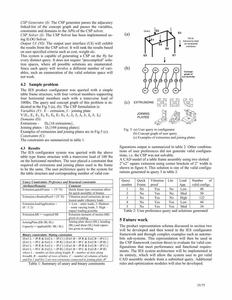
CSP Generator (I): The CSP generator parses the adjacency linked-list of the concept graph and passes the variables, constraints and domains to the APIs of the CSP solver. CSP Solver (I): The CSP Solver has been implemented us-ing ILOG Solver. Output UI (NI): The output user interface (UI) will exhibit the results from the CSP solver. It will rank the results based on user specified criteria such as cost, weight etc. This system is capable of generating a CSP on the fly for every distinct query. It does not require “precompiled” solu-tion spaces, where all possible solutions are enumerated. Since each query will involve a different number of vari-ables, such an enumeration of the valid solution space will not work.
4.2 Sample problem
The IES product configurator was queried with a simple table frame structure, with four vertical members supporting four horizontal members each with a transverse load of 100lbs. The query and concept graph of this problem is in-dicated in the Fig 5 (a), (b). The CSP formulation is: Variables (V): E – extrusion, J – joining plate V{E1, E2, E3, E4, E5, E6, E7, E8, J1, J2, J3, J4, J5, J6, J7, J8}Domains (D):Extrusions - DE{16 extrusions}, Joining plates – DJ{104 joining plates} Examples of extrusions and joining plates are in Fig.5 (c). Constraints (C):The constraints are summarized in table 1.
4.3 Results The IES configurator system was queried with the above table type frame structure with a transverse load of 100 lbs on the horizontal members. The user placed a constraint that required all extrusions and joining plates used in the frame to be the same. The user preference query to the system for the table structure and corresponding number of valid con-
Unary Constraints: Preference and Structural constraints
Attribute(Domain) Comment
Extrusion.quickFrame = (Y/ N) Quick frame type extrusions allow for quick assembly of frames
Extrusion.vibrationProof = (Y/ N) Vibration proof extrusions do not loosen under vibratory loads
Extrusion.loadApplication = (0 / 1/ 2)
1: Low – static loads, 2: Medium – some varying loads, 3: High – impact loading possible
Extrusion.MI >= required MI Extrusion moment of inertia (MI) given in catalog
JoiningPlate.(DL/BL/SL) Capacity>=applied(DL/ BL/ SL)
Joining plate direct (DL), bending (BL) and shear (SL) load capaci-ties given in catalog
Binary constraints: Mating constraints
(Ext1.L = JP.R & Ext2.L = JP.C) || (Ext1.B = JP.R & Ext2.B = JP.C) || (Ext1.L = JP.C & Ext2.L = JP.R) || (Ext1.B = JP.C & Ext2.B = JP.R) || (Ext1.L = JP.R & Ext2.L = JP.C) || (Ext1.B = JP.R & Ext2.B = JP.C) || (Ext1.L = JP.C & Ext2.L = JP.R) || (Ext1.B = JP.C & Ext2.B = JP.R) where L – number of slots along length, B – number of slots along
breadth, R – number of rows of holes, C – number of columns of holes
and Ext 1 and Ext 2 are two extrusions connected to joining plate JP
Table 1: Summary of unary and binary constraints
figurations output is summarized in table 2. Other combina-tions of user preferences did not generate valid configura-tions, i.e. the CSP was not solvable. A CAD model of a table frame assembly using two slotted 2”x2” square extrusion using corner brackets of 2” width is shown in figure 6. This solution is one of the valid configu-rations generated in query 3 in table 2.
Query number
QuickFrame
Vibration proof
Lite Load App.
Number of valid configs.
1 No Yes No Low 48 2 No Yes No Med 50 3 No Yes No High 122 4 No Yes Yes Low 44 5 No Yes Yes Med 34
Table 2: User preference query and solutions generated
5 Future work
The product representation schema discussed in section two will be developed and then tested in the IES configurator framework and through complex examples such as automo-bile sub-systems. This representation will then be used in the CSP framework (section three) to evaluate for valid con-figurations that meet performance and functional require-ments. The IES system architecture will be implemented in its entirety, which will allow the system user to get valid CAD assembly models from a submitted query. Additional rules and optimization modules will also be developed.
(a)
(b)
(c)
Fig. 5: (a) User query to configurator (b) Concept graph of user query (c) Examples of extrusions and joining plates
35/75

Acknowledgements
We would like to thank Rajasekar Karthik for his help in the implementation of the IES product configurator.
References
[Allison04] Allison, J.T., Complex System Optimization: A Review of Analytical Target Cascading, Collaborative Optimization, and Other Formulations. Master’s thesis, University of Michigan, 2004.
[Ashby99] Ashby, M. F. Materials Selection in Mechani-cal Design, Second ed., Butterworth Heinemann, Ox-ford, UK. 1999
[Dieter99] Dieter, G. E. Engineering Design: A Materials and Processing Approach, Third ed., McGraw-Hill, New York, USA. 1999.
[Felfernig01] Felfernig A., Friedrich G., Jannach D., Zanker M., Towards Distributed Configuration, Proc. 24th German/ 9th Austrian Conference on Artificial Intelli-gence, 918 – 212, 2001
[Freuder89] Freuder, E. C., Wallace, R. J. Partial Constraint Satisfaction. Proc. of the Eleventh International Joint Conference on Artificial Intelligence, IJCAI-89: 278-283, 1989.
[Freuder95] Freuder, E., Dechter, R., Selman, B., Ginsberg, M., and Tsang, E., Systematic Versus Stochastic Con-straint Satisfaction, Panel, IJCAI-95:2027-2032, 1995.
[Gelle00] Gelle, E., Faltings, B., Smith, I., Structural engi-neering design support by constraint satisfaction. Artifi-cial Intelligence in Design: 311 – 331, 2000.
[Gelle03] Gelle, E., Faltings, B., Solving mixed and condi-tional constraint satisfaction problems, Constraints,8:107 – 141, 2003
[Gelle04] Gelle, E.,, Consistency Rules for Modelling Technical Systems based on IEC 61346, Configuration Workshop at ECAI 2004, Valencia, August 2004.
[Gero90] Gero, J.S. Design prototypes: a knowledge repre-sentation schema for design. AI Magazine, 11(4): 26-48, 1990.
[Larossa98] Larossa, J. Algorithms and heuristics for total and partial constraint satisfaction, PhD dissertation, Universitat Politecnica de Catalunya, 1998
[Mailharro98] Mailharro, D., A classification and con-straint-based framework for configuration, AIEDAM, 12: 383 – 397, 1998.
[Michelena99] Michelena, N., Kim, H. M., Papalambros, P. A system partitioning and optimization approach to tar-get cascading. International Conference on Engineering Design, ICED-99, Munich, 1999
[Mittal90] Mittal, S., Falkenhainer, B., Dynamic constraint satisfaction problems, Proceedings of the 8th National Conference on Artificial Intelligence: 25-32, 1990.
[Roy97] Roy, P., Liret, A., Pachet, F., A framework for ob-ject-oriented constraint satisfaction problems, Object-Oriented Frameworks, ACM Press, Eds. Fayad, M., Schmidt, 1997.
[Saitou04] Saitou, K., Lyu, N. Decomposition-based assem-bly synthesis of space frame structures using joint li-brary, Proceedings of DETC’04, DETC-04, Salt Lake City, UT, 2004.
[Shigley01] Shigley, J. E., Mischke, C. R., Mechanical En-gineering Design, 6ed., McGraw-Hill, 2001
[Stumptner98] Stumptner, M., Friedrich, G., Haselboeck, A., Generative Constraint-Based Configuration of Large Technical Systems, Special Issue on Configuration: Arti-ficial Intelligence in Engineering, Design, Analysis and Manufacturing, 12(4), December 1998
[Soininen99] Soininen, T., Gelle, E., Niemela, I., A Fixpoint Definition of Dynamic Constraint Satisfaction, 5th Inter-national Conference on Principles and Practice of Con-straints Programming – CP99: 419-433, Alexandria, VA, 1999.
[Szykman01] Szykman, S., Fenves, S. J., Keirouz, W., Shooter, S. B. A foundation for interoperability in next-generation product development systems. CAD, 33:545 – 559, 2001
[Tsang90]Tsang, E. P. K., Warwick, T., Applying genetic algorithms to constraint satisfaction problems, Proceed-ings European Conference on AI, ECAI90: 649 – 654, 1990.
[Wong93] Wong, A., Sriram, R. D. SHARED: an informa-tion model for cooperative product development. Re-search in Engineering Design, 5(1):21 – 39, 1993
[Xue04] Xue, D., Yang, H. A concurrent engineering-oriented design database representation model. CAD, 36: 947 – 965, 2004.
[Yokoo00] Yokoo, M., Hirayama, K., Algorithms for Dis-tributed Constraint Satisfaction: A Review, Autonomous Agents and Multi-agent Systems, 3(2): 198 – 212, 2000.
Fig. 6: Table frame CAD model
36/75

Configuring Loopholes: InteractiveConsistency Maintenance of Business Rules
Markus Stumptner, Michael Schrefl�
Abstract. Business rules are the core of information sys-tems. They define under which conditions certain actionsmay, must not, or need to be taken. Business rules are oftencollected as such during analysis, but are frequently buriedduring implementation in different form of application code(within procedures, as pre- or postconditions, or as databasetriggers). Part of the conceptual design process is to makebusiness rules explicit and associate them with activities ofobject types.
Object-oriented design methods, such as UML, organiseobject types in pecialisation hierarchies. In the past, vari-ous consistency notions have been eveloped for specialisingmethods (co- and contra-variance), for specialising object-life cycles (observation- and invocation-consistency), and forspecialising active rules (database triggers) in object-typehierarchies.
This paper complements these past research results byintroducing an application-oriented perspective for the spe-cialisation of business rules. Using the notion of "decisionconsistency", we introduce a specialization model for busi-ness rules that is aligned with commonly used principles inorganizational contexts to guarantee consistency betweendecisions at a higher legislative level (e.g., European Union)and at a lower level (e.g., a member state).
1 IntroductionBusiness rules are the fundamental tool for decision mak-ing. They provide a system of rules that define conditionsunder which actions may execute. In a company, actionsare defined at several levels. As this fact does not providea comparable consideration of similar initial situations, itis necessary to find a universal/general treatment for deci-sion making.
In this paper we present a modularization of businessrules which we call ’decision consistency’ such that deci-sions made on a certain level of authority is comprehendedand understood on a higher level of authority. Moreover,this modularization guarantees that decisions made at ahigher level are still valid on a lower level. This is what wecall decision consistency. We use object/behavior diagramsto model business processes and their associated businessrules. Then a business process is an object type and busi-ness rules are defined as conditions which properties of abusiness process have to satisfy. Consider for instance theexample of a credit allowance.
Example 1 A credit institution gives credit to its customers.�
Advanced Computing Research Centre, University ofSouth Australia, 5095 Mawson Lakes (Adelaide) SA,mst � [email protected]
If a person applies for a credit, the creditworthiness of theclient has to be checked. For this reason, the case officer han-dling the credit must collect sufficient information about theclient to make a decision.
In addition, different types of credit exist, for examplehome loans and mortgages, and particular types of creditmay be granted by particular divisions in the enterprise, e.g.,private loans and mortgages2 would be handled by a differ-ent division from business loans.
The natural way of modelling business rules in databaseapplications is by expressing them as ECA (Event-Condition-Action) rules [WC96] - when particular businesssituations arise, the rules are activated and executed, possi-bly activating further events. Conceptual database modelshave long used object-oriented concepts, and object-orientedand object-relational databases associate business ruleswith particular classes describing domain entities [CCS94]that are integrated into complex business processes. Thissituation gives rise to the arrangement of rules in inheri-tance hierarchies, an issue that has been studied (mostly interms of separately modeling inheritance of events, condi-tions, and actions) for several years [CMR98, BGM00]. Thegeneral principle is that of specialisation (i.e., semanticallyconsistent inheritance) [SS02]: the actions executed in asubclass must be compatible with the actions executed ina superclass under the same event (or a supertype of thatevent). In the context of business rules, we assume thatthe specialisation hierarchy of rules follows that of businessprocesses, and the business processes follow the structure ofthe company, as does the power to make decisions. This isa principle in conceptual rule modeling: An enterprise willtypically define a set of rules that describe guidelines thatare global to the enterprise (similar to the global schema inthe classical 3-Level CODASYL database architecture), andlower level administrative units will have to to function (i.e.,define their own rules) within that framework.
This means that particular divisions or functional areasin the enterprise may define their own rules, however theserules have to satisfy two conditions which summarise thenotion of Decision Consistency:
1. More specific rules (e.g., division-specific rules) comprisethe enterprise-wide rules, i.e., both division and enter-prise specific rules must be covered
2. More specific rules may not contradict the more generalrules, i.e., the division specific rules must uphold theprinciples set up by the encompassing organisation.
�In a mortgage, some asset of the client’s is listed as a security incase the client defaults on the loan.
37/75

Example 2 In our example, the enterprise (a bank or otherfinancial institution has general rules about providing loansto customers. Particular divisions that are respnsible for pri-vate loans or mortgages will introduce separate businessrules that need to be satisfied in their special situations (cf.Figure 1).
decision rules
Loan
Private Mortgage
scope of enterprise−widedecision rules
scope of division−specific
Figure 1. Specialisation of business rules
The formal description of a business rule is as a set ofboolean conditions (constraints) over so-called object situa-tions � � � � � � � � � associated with particular activities inthe model. For a given activity � at class � we distinguishthe following conditions as definable by a rule:
� Conditions determining obligations � �� . If an obligationcondition is satisfied, action � must be executed.
� Conditions referring to forbidden actions � �� . If an obliga-tion condition is satisfied, action � must not be executed.
� Conditions referring to permissions � �� . If a permissioncondition is satisfied, action � can be executed, but neednot be.
We refer to � � � , or � as the mandate given by the rule.It is � �� that is required to enable interactive operation:
the business rules can explicitly specify openings that areleft to the case worker’s judgment concerning the choice ofparticular actions. We add the axiom that � �� and � �� aremutually contradictory, i.e., it is not acceptable that thesame action is prescribed and prohibited at the same time(this is satisfied in the rules depicted in figure 2 and 3). Notealso that � � �� � � ! " � �� � � ! does not need to hold.
In the grant example, the three actions available aregrant ( & , the case worker decides that the application suc-ceeds), reject ( ' , the application is unsuccessful), and for-ward ( ( , the case worker is not authorised to make a deci-sion because this is a borderline case that has to be forward,e.g., to a board of experts that will make the actual deci-sion). The parameters governing the three actions are theloan amount , the return payment rate ) , and the dispos-able income, * . The coordinate axes are the same for all fig-ures: as specified in the first, they correspond to and * , ) ,respectively. The second column of the table below specifiesthe different action conditions for the general loan category.Figure 2 (right) and 3 show the constraints for each actionseparately. We refer to the n-dimensional space describedby the parameters used in the rule (where . is the numberof parameters) as the rule’s decision space.
The example is a very simple process with a single step;in general earlier actions could be part of the conditions.I.e., essentially a stepwise workflow is described via a set ofrules, leading to a larger constraint network.
2 Decision Consistent SpecializationTo examine the situation of business rules specialisation,we follow the organisational view described in the previous
d/r
Or
L
Og
Fg Pf
Fr
Of
Or
L
Fr
l
Figure 2. Loan rules: all actions (left); reject (right)
Og=Pg
Ff
L
Ff
OfPf
L
Fg
Figure 3. Loan rules: forward (left); grant (right)
section. While the overall organisation has business rulesdescribing the general version of a process, subinits of theorganisation have more rules dealing with more specific ver-sions of that process, i.e., their business rules are associatedwith subunit-specific subclasses of the generic business ob-ject.
We use the example of specializing general loan requeststo private loan requests. The handling of a request for a pri-vate loan differs from a generic loan request insofar as twoadditional activities are necessary before the requester’scredit rating can be evaluated: checking with the credit rat-ing association, and identifying the amount of salary avail-able for impounding if the recipient defaults upon the loan.A mortgage differes from the standard credit rating pro-cess by the need to estimate the value of the property be-ing mortgaged, determining the ownership conditions, andidentifying the result limit of the mortgage. The correctintegration of the new activities and states into existingdiagrams depicting the lifecycle of an application objectwas described in [SS00] for Object/Behavior Diagrams andin [SS02] for UML. Likewise, the specialisation of a set ofbusiness rules that refer to a specialized object type has toobey certain conditions that are consistent with the set ofrules defined for the original object type.
In particular, the idea is that the set of rules for the sub-type should encompass the space of all decisions made bythe supertype, but on the other hand, the rules defined forthe subtype should not contradict the decisions made for thesupertype. In other words, for a given � 0 2 � 5 7 . � 8 � . * � � = �pair, the subtype’s rules decision spaces need to be consis-tent with the decision spaces of the rules in the supertype.
Example 3 In our banking example, the above informalcriteria imply that a private loan must be granted if it mustbe granted under the rules specified for general loans. In ad-dition, they must not be granted if the rules for a generalloan say that it must be rejected. Private loans have as anadditional property the impoundable income 5 .
38/75

For reasons of simplicity we use the same set of actionsfor the supertype and the subtype; the normal assumptionin rules inheritance is that the actions used in the subtypecan themselves be specialisations of the actions in the su-pertype [CMR98, BGM00]. In that case, the subtype ac-tions need to be projected back to their supertype coun-terparts to test for consistency of the subtype’s rule’s de-cision space. This notion has been explored in more detailin [KS95, BS94].
Loan Type/ Ac-tivity
Loan Private Loan
Loan refusalobligatory(must)
� �� � �
� ( � �� � �
� � or� �
� � �� and
� � � )Loan refusal for-bidden
� � � � �� ( � � �
� � or( � � � � �
� and� � � )
Passing on toboard obligatory
� � � � �� and� � � � ( � � �
� and� � � � �� or
( � � � � �� and
� � � )Passing on toboard obligatory
� � � � �� and� � � � ( � � �
� and� � � � �� or
( � � � � �� and
� � � )Passing on toboard forbidden
� � �� � �
� � or( � � � � �
� and� � � � �)
� � �� � �
� � or( � �
� � �� and
� � � ) or( � � �
� and�� � � �
� or( � � � � �
� and� � � and�
� � � �)
Loan offer oblig-atory
� � � � �� and�
� � � � ( � � �� and�
� � � �) or
( � � � � �� and
� � � and�� � � �
)Loan offer for-bidden
� �� � �
� or� � � � ( � �� � �
� ) or( � � � and
� � � ) or(
� � � � �)
The critical notion is whether the original rules leave anyroom for maneuver. This situation arises when the rules fora given object type do not apply in all possible situationsdescribed by the object type, corresponding to cases wherehuman worker or manager would be called upon to makethe actual loan decision. Inheritance means the additionof new properties and constraints; inheritance at the ruleslevel means that parts of the rule’s decision space that wereleft unspecified or in Permitted status may be in Obligatoryor Forbidden status in the subclass.
Figure 4 show the decision space for a Private Loan (PL);since we are now dealing with 3 parameters (3 dimensions)we have to use two diagrams. Note that in the case for � � ,part of the “permitted” space actually becomes forbidden togrant, but there is still an open choice as these applicationscan be either forwarded or rejected.
3 Reasoning
To reason about business rules we represent them as con-straints in the fashion described above: the condition sim-ply implies a particular assignment. E.g., the constraint
For i<r
OrOf
Og
P(r v f)F(g)
PL
Or
PL
Of
Og
For i>=r
Figure 4. Private Loan
corresponding to the first rule in the table is � �� � �
� �� � � � � � � � � � � � � � � .
Apart from “firing” it as a rule in the usual fashion (fol-lowing the implication), there are two other modes in whichwe can reason about the set of rules. Checking for consis-tency wih a given mandate and action after adding the in-compatibility axiom mentioned above, i.e., � �� � " �� , andits super/subtype versions � �� � � " �� , � �� � " �� � , where o’is the subtype of o, is a check for consistency of the inheri-tance relationship.
Conversely, when using a constraint solver that can rea-son about algebraic epxressions, we could use it and therequirement that the subtype rule does not contradict thesupertype rule to infer an appropriately restricted versionof the subtype rule from a version that is not restrictedenough. This can be used as an interactive tool to guidesubtype rule development; the constraint solver guaranteesthat the subtype’s rules will either correspond to an O or Fmandate in the supertype in the same area of the decisionspace, or make a new O or F mandate fit in the “Permitted”or unspecified part of the supertype’s rule’s decision space.
References[BGM00] Elisa Bertino, Giovanna Guerrini, and Isabella Merlo.
Trigger inheritance and overriding in an active objectdatabase system. 12(4):588–608, July 2000.
[BS94] P. Bichler and M. Schrefl. Active Object-OrientedDatabase Design Using Active Object/Behavior Dia-grams. In J. Widom and S. Chakravarthy, editors, Proc.IEEE RIDE’94, pages 163–171, Houston, 1994.
[CCS94] Christine Collet, Thierry Coupaye, and T. Svensen.NAOS - efficient and moduler reactive capabilities inan object-oriented database system. In Proceedings ofthe International Conference on Very Large Databases(VLDB), pages 132–143, 1994.
[CMR98] Nauman A. Chaudhry, James R. Moyne, and Elke A.Rundensteiner. A formal model for rule inheritance andoverriding in active object-oriented databases. In Pro-ceedings 3rd Integrated Design and Process TechnologyConference (IADT ’98), pages 128–135, 1998.
[KS95] Peter Kueng and Michael Schrefl. Spezialisierung vonGeschaeftsprozessen am Beispiel der Beantragung vonKreditantraegen. HMD, 185, 1995.
[SS00] M. Stumptner and M. Schrefl. Behavior consistent in-heritance in UML. In Proc. Intl. Entity-RelationshipConference (ER 2000), Salt Lake City, October 2000.
[SS02] M. Schrefl and M. Stumptner. Behavior consistent spe-cialization of object life cycles. ACM Transactions onSoftware Engineering and Methodology, 11(1):92–148,2002.
[WC96] Jennifer Widom and Stefano Ceri. Active Database Sys-tems: Triggers and Rules for Advanced Database Pro-cessing. Morgan Kaufmann Publishers, Inc., 1996.
39/75

Interactive Configuration and Evaluation of a Heat Treatment Operation
M. Aldanondo(a)
, E. Vareilles(a)
K. Hadj-Hamou (b)
and Paul Gaborit(a)
(a) Centre de Génie Industriel - École des Mines d'Albi-CarmauxCampus Jarlard - 81013 Albi CT Cedex 09 - France
(b) Laboratoire GILCO - ENSGI – INP Grenoble 46 Avenue Félix Viallet - 38031 Grenoble - France
{aldanondo, vareilles, gaborit}@enstimac.fr, [email protected]
- part material, characterised by parameters relevant to chemicalcomposition and mechanical/thermal/structural behaviours,
Abstract
- part geometry, characterised by parameters relevant to the shape,massiveness, symmetry of the part,
This paper presents an interactive configurationsystem that allows solution evaluation. This work is driven by an industrial case dealing with heat treatment operation. The first part presents the problem and provides the main solution ideas. Then the configuration model mixing discrete and numerical constraints is presented. The third sectionprovides filtering elements in order to permitinteractive configuration. The last one discusses thedesigned configuration/evaluation system.
- heat treatment conditions, characterised by parameters describing the heating device, the cooling system, the parts layout duringheating and quenching and various tuning (duration, temperature,flow-rate…).
All these parameters are linked by constraints. Configuring a heat treatment operation corresponds with the selection of a value for each of these parameters with respect to all the constraints.
In order to have a configured heat treatment operation that satisfies the user, it is necessary to evaluate the improvement of the mechanical properties of the part but also to evaluate if the level of relevant distortion is acceptable. If the way to select the parametersdefining the heat treatment operation in order to improve the mechanical properties is well known, distortion prediction is much more delicate. The scope of evaluation is therefore to qualitativelyquantify distortion (i) during the configuration process in order to interactively assist the user and (ii) at the end of the configuration process in order to compare different configured heat treatmentoperations.
1. Introduction
The goal of this communication is to present an interactive configuration system that simultaneously allows interactive configuration and qualitative evaluation. This problem originatesfrom a European project called VHT for “Virtual Heat Treatment”(project No G1RD-CT-2002-00835) whose purpose is to set up a Knowledge Based System able to configure and evaluate heattreatment operation.
1.1 – The industrial problem
1.2 – The proposed solutionA heat treatment operation consists in raising the temperature of asteel part until a certain temperature, remaining at this temperaturefor a while, then cooling down rapidly. The expected effect is an improvement of the mechanical properties of the part. But,simultaneously, a negative effect corresponding with part distortions occurs most of the time.
Most works related to configuration techniques concern physicalproducts. The configuration of process operations has been much less studied. [Geneste et al 2000] proposed an application dealing with a machining operation. In their work, configuration is interactive and is used in an interactive process for aiding decision. In a similar way,the proposed application deals with the interactive configuration of aheat treatment operation. Furthermore, it computes, after each inputs, the intensity of the final distortion of the configuration problem, with some numerical constraints filtering techniques.
The means to evaluate distortions is computer-simulation thanks to Finite Element Method Codes (FEM). They allow obtainingquantitative prediction of the distortion at the design stage. However these tools are costly, time consuming and very complicated to use(due to mechanical/thermal/structural behaviours and data requirements). The situation is getting even more difficult in the current context of smaller production series and the high reactivity of the market. Due to the lack of satisfying simulation-based tools, prediction of distortion relies mostly on the know-how from heat treatment experts or users. Therefore the idea of collecting the know-how about heat treatment distortion and to organize it in aKnowledge Based System is at the origin of this work. The whole system gathers a CBR module and a configuration module. This communication deals with the configuration/evaluation module.
A way to compute the evaluation of a configuration solution is to assign weights to each parameter values and to each allowedcombinations of parameter values relevant to constraints. Both thequality of the chosen values and the resulting associations of values usually influence the goodness of a solution. The evaluation of asolution is defined as the sum of the weights of all the values andpairs of values involved in the solution [Hulubei et al 2003]. The main interest of this approach lies in its simplicity and itsoptimisation possibilities. But in an interactive configuration process, this approach does not easily allow the user to input some constraints on the result and to see the consequences on the parameter values. In our case, the possibility to input a maximum value on distortion and
A heat treatment operation can be defined according to:
40/75

to configure with respect to this constraint is a necessity. Therefore, it was decided to embed the evaluation process in the configuration process. In our case, this means, that distortion and formulae thatcompute distortion are considered in the configuration model.
The resulting configuration model gathers: - two sets of variables corresponding with:
- heat treatment parameters {vp}, - distortion attributes{vd},
- constraints linking:- only vp, necessary for heat treatment configuration, - vp and vd, necessary for computation of the distortion.
Two ways of using the configuration system are therefore possible.The first one consists in interactively inputting parameter values and getting the computation of the relevant distortion. The second oneconsists in first inputting parameter values that are not negotiable (part shape for example), then inputting some threshold on the maximum value of the distortion in order to get domain restrictions on negotiable parameters (heating rate for example).
1.3 – Paper organization
The second section presents the configuration model gathering two configuration and evaluation model pieces. It will show that three kinds of constraints are necessary: discrete constraints, numericalconstraints and mixed constraints. As we target an interactive assistance, the filtering elements for each kind of constraints will bedescribed in section three with the means to gather them in a single filtering engine. Then some interest and limits of the system will be discussed in the last section.
2 The knowledge model
The goal of this section is to present an overview of the configuration model. This section is divided in two parts. The first one describes the model piece necessary for configuring the heat treatment operation. The second one deals with the evaluation ofdistortion and shows how the two model pieces fit together.For each sub-section, the model is described as a ConstraintSatisfaction Problem (CSP) [Tsang 1993] and outlines the kind of variables and the kind of constraints that are necessary. Variousmodels were designed with heat treatment experts, coming both from academia and industry, through a dozen of meetings plannedduring the past 18 months [David et al 2003]. The most advance one concerns parts that belong to a part family “axis” (one dimension much longer than the two others). Another model dealing with a part family “disc” (one dimension much smaller than the two others) is currently investigated.
2.1 – Piece of model relevant to heat treatment configuration
Around 50 parameters have been identified by the experts andcharacterize the material of the part, the geometry of the part or theheat treatment conditions. Each parameter is associated with a configuration variable upon which the user can input a domain restriction. These variables are either symbolic or numerical. Sometypical variables are shown in the table 1.
Symbolic
forming_processdelivery_structure
Part material
……
hole_existenceshoulder_existence
Part geometry
……quenching_fluid_typegravity_direction
Heat treatmentconditions
……
Numerical
carbon_percentageroughness_variation
Part material
……average_diameterthickness_variation
Part geometry
……quenching_fluid_temperatureheating_rate
Heat treatmentconditions
……
Table 1 – Configuration variables
2.1.1 - Compatibility constraints
Most of the constraints relevant to heat treatment configuration are compatibility constraints expressing restrictions on variable values. As variables are either symbolic or numerical, different kinds of constraints are present.
Constraints between the symbolic variables correspond with compatibility tables as the one shown in table 2 providing the kindof fluid behaviour with respect to the quenching fluid type.
quenching_fluid_type fluid behaviour“water” “turbulent”“water” “laminated”“gas” “turbulent”…. …..
Table 2 – Discrete constraint
Constraints between numerical variables can correspond with :(i) simple mathematical operations ( +, - , * , / ), as for example atemperature increase computation : Delta_temp = Temp_max – Temp_min(ii) compatibility tables, when heat treatment experts can providecompatibilities between intervals, as for example a compatibilitybetween a furnace load and a heating speed shown in table 3.
furnace_load heating_speed[0, 500] [15, 25]
[250, 750] [10, 15][500, 1000] [5, 10]
….. ….
Table 3 – Numerical constraint
or (iii) experimental curves or abacus, they require morecomplicated discretization techniques as Quad Trees proposed by[Sam 1995] that have been successfully investigated but will not bedetailed in this communication.
Constraints mixing symbolic and numerical variables are alwaysexpressed thanks to compatibility table as the one in table 4
41/75

showing a relation between the fluid speed and the type ofquenching fluid.
Banana
Spool / Barrel
Tightening / Spacing
Ovalization
Umbrella : right handle / left handle
Banana
Spool / Barrel
Tightening / Spacing
Ovalization
BananaBanana
Spool / BarrelSpool / Barrel
Tightening / SpacingTightening / Spacing
OvalizationOvalization
Umbrella : right handle / left handleUmbrella : right handle / left handle
Figure 2 – Five distortion types
quenching_fluid_type fluid_speed“water” [0.5, 2]
“oil” [0.5, 2]“gas” [2, 10]…. …..
Table 4 – Mixed constraint
2.1.2 - Activity constraints
In order to be able to modulate the existence of some parameters, it is necessary to be able to express some variable existence conditions. This kind of constraints, called activity constraint in the dynamic extension of CSP [Mittal and Falkenhainer 1990], have thefollowing shape, X = “x” => Y exists, meaning if variable “X”equals the value “x” then variable “Y” exists. They have been mainly used to describe geometric parameters of the part as for example:hole_existence = “yes” => Variable_hole_diameter exists. part_thickness [10 , 20] => Variable_part_area exists.
2.1.3 - Conclusions
For the model piece relevant to heat treatment configuration, we deal with (i) a set of variables vp that are symbolic or numerical, (ii) constraints that can be discrete, numerical or mixed and (iii) compatibility and activity constraints. Figure 1 (where circles arevariables and lines correspond with constraints) illustrates this simple piece of model.
{vd_pot} {vd_int} {vd_fin}
{vp}
{vd_pot} {vd_int} {vd_fin}{vd_pot} {vd_int} {vd_fin}
{vp}
Figure 3 – Three kinds of distortion attributes
2.2 – Piece of model relevant to the evaluation of distortion
As part distortion is geometrically very complicated to describe,heat treatment experts have proposed to quantify five basic distortion shapes: (i) “spool/barrel”, (ii) “banana”, (iii) “ovalization”, (iv) “spacing/tightening” and (v) “umbrella”, asshown in figure 2. It can be noted that (i) “spacing/tightening”distortion can exist, if the part has got a hole, in the left and/or right part extremities and (ii) “umbrella” distortion can exist if shoulder shapes are present.
2.2.1 – Evaluation variables
Each of these five distortion components is associated with somekind of grade. In order to calculate such a value, heat treatmentexperts propose the following approach based on three kinds ofdistortion attributes:- a first small subset of heat treatment parameters, vp, allows a firstquantification of each distortion component, named potential distortion attribute, vd_pot,- a second larger subset of heat treatment parameters, vp, permits to quantify intermediate distortion attributes, vd_int. These attributes
modulate each potential distortion component in a similar way.Around 26 intermediate distortion attributes have been identified. - the resulting grade of each distortion component, named final distortion attribute vd_fin, is computed as a product of the relevant potential distortion attribute and the set of intermediate distortion attributes.This is illustrated in figure 3 with a model gathering two distortion components (two couples (vd_pot , vd_fin)) and three intermediate distortion attributes (vd_int). The solid lines represent the possiblerelation between parameters and various distortion attributes.
{vp}{vp}
Figure 1 – Configuration model
Each distortion attribute is associated with a configuration variable. These variables are all numerical and defined within intervals. Inorder to compare solutions, heat treatment experts decided that (i) each final distortion component (vd_fin) is quantified into an interval [1, 1000], where “1” means no distortion and “1000” means maximum distortion, (ii) each potential distortion component(vd_pot) is quantified into an interval [1, 20] while (iii) eachintermediate distortion attribute (vd_intk) is quantified into intervals[1, k] such their product belongs to an interval [1, 50].
42/75

3 - Filtering techniques 2.2.2 – Evaluation constraints
As potential and intermediate distortion attributes are all numericaland parameters either symbolic or numerical, constraints linking these distortion attributes with parameters are either mixed or numerical. All these constraints have been expressed thanks to compatibility tables: (i) 5 constraints for the quantification of the 5 components of potential distortion (vp, vd_pot) and (ii) 26 constraints for the quantification of the 26 intermediate distortion attributes (vp, vd_int).
The object of this section is to present the various filtering techniques that have been necessary and show how they have been gathered in a single filtering engine.
3.1 - Discrete constraints defined with compatibility tables
A simple arc consistency technique (AC-3) has been used to propagate this kind of constraints. As some constraints have an aritylarger than two, AC-3 has been adapted. The filtering techniques work as follows:As each final distortion component is obtained with the
computation of the product of the relevant potential distortioncomponent and the set of intermediate distortion attributes, the following numerical constraint: vd_fin = vd_pot* k=1 to 26(vd_intk)must be defined for each of the five distortion components.
1-Input on variable var-x 2- Put var-x in list-var-1 3- While list-var-1 non empty:
4- Take variable var-i of list-var-1 This is illustrated in the lower part of figure 4 with the example of model of figure 3.
5- Put constraint including var-i in list-cst-1 6- While list-cst-1 non empty:
7- Take cst-j of list-cst-1 2.3 – Gathering the two model pieces in a single model 8- Filter cst-j with var-i
9- Put var, with a reduced domain, in list-var-1 The two model pieces are gathered in a singleconfiguration/evaluation model (figure 4) showing:
3.2 - Mixed constraints defined with compatibility tables - two kinds of variable associated with:
- parameters (vp): around 70 symbolic and numericalvariables,
For compatibility tables including numerical variables defined withintervals, the association of a label with each interval permits toconsider a discrete constraint [Faltings 1994]. The previous filtering means (3.1) can be used except that when the definition domain of anumerical variable is reduced, it is necessary to reconstruct the definition domain of the variable with classical set operations(union, intersection). Filtering therefore goes as follows :
- distortion attributes (vd_pot, vd_int, vd_fin): around 40numerical variables,
- three kinds of constraints between:- parameters (vp): around 40 constraints, gathering activity and
compatibility constraints, which can be symbolic, numericalor mixed constraints and mainly expressed thanks to compatibility tables, 7- Take cst-j of list-cst-1
- parameter (vp) and distortion attributes (vd_pot, vd_int): around 50 compatibility constraints which can be numericalor mixed constraints and which are described as compatibilitytables,
8- Filter cst-j with var-i 8’- Reconstruct definition domain of the reduced var 9- Put var, with a reduced domain, in list-var-1
- distortion attributes (vd_pot, vd_int, vd_fin), around 60constraints which are numerical compatibility constraints,
and defined with the “product” mathematical operation,
3.3 – Continuous constraints defined with compatibility tables
The previous labelling and domain reconstruction means are used in order to filter this kind of constraints.
{vd_pot} {vd_int} {vd_fin}
{vp}
{vd_pot} {vd_int} {vd_fin}{vd_pot} {vd_int} {vd_fin}
{vp}
Figure 4 – Global configuration/evaluation model
3.4 - Continuous constraints defined with simple formulae
When all the variables are numerical and each constraint writtenwith a mathematical formula, f(x1, x2,…xn) = 0, B-Consistency,proposed by [Lhomme 1993] and based on interval analysis [Moore 1966], proposes filtering techniques that operate fine if: (i) f(x1, x2,…xn) = 0 can be projected on any variable xi meaningthat a function fi exists as: xi = fi(x1,x2….xi-1, xi+1,…xn)(ii) any projection fi is continuous and monotonous.(iii) only one constraint expressed as a formula acts on a samevariable subset. B-Consistency is weak when more than one constraint acts on a same sub-set of variables (corresponding tosome constraint intersection). It is shown in [Lhomme and Rueher 1997] that a simple problem gathering two variables and three constraints cannot be fully filtered.(iv) each variable occurs only on time in a formula. In the oppositecase, for example: x12 - x1 - x2 = 0, it has been shown that the wayto express the mathematical expression, for example: x12 - x1 - x2 = 0 or x1*(x1 - 1) - x2 = 0, influences the quality of the filteringoperation [Lhomme, Rueher, 1997].
The object of the next section is to study how this model can beused to interactively and simultaneously allows configuration and evaluation of the heat treatment operation.
43/75

As this kind of constraints is only present in our model: (i) between configuration parameters, vp, with simple mathematical operation (+, - , * , / ) and (ii) for computing the product quantifying the final distortion attribute (vd_fin = vd_pot * 1 to 26(vd_int)), the previousrestrictions are not present and B-Consistency can be used. For asingle continuous constraint, filtering is done as follows:
4 – Interest and limits of the proposed approach
All these elements have been set up in a software mock-up that can be seen on the web at: http://iena.enstimac.fr:20000/cgi-bin/vht.pl.Two ways to use the configuration system have been identified at the end of section 1.2. The first one, consisting in interactivelyinputting restrictions only on parameter and see the computation of the relevant distortion raises an interesting point. While the other, inputting parameter restrictions (that are not negotiable) and somethreshold on the maximum value of the distortion in order to get domain restrictions (on negotiable parameters), points out a limit of the approach.
1- Input on variable var-x 2- Put var-x in list-var-1 3- While list-var-1 non empty:
4- Take variable var-i of list-var-1 5- Put all constraint projections including var-i in list-cst-1 except the one relevant to var-i 6- While list-cst-1 non empty: During the interactive configuration process, each time the user
inputs a restriction on a variable corresponding with a parameter(vp), constraints are filtered and other parameters (vp) and/or distortion attributes (vd) have their domain reduced without anyproblem. If this behaviour is normal and expected in interactive configuration for parameters (vp), it is of interest for distortionevaluation (vd).
7- Take constraint projections of list-cst-1 8- Compute the resulting domain of the projected variable 8”- Intersect resulting domain with initial domain of theprojected variable 9-If domain is reduced, put projected variable in list-var-1
3.5 – Activity constraints At the beginning of configuration process, each final distortionattribute has a definition domain equal to the interval [1, 1000]meaning that no information about distortion level is available. As filtering is launched after each user input, each final distortion domain is progressively reduced during the configuration process. The example of figure 5 shows how the intensity of the banana distortion decreases when, first, the geometry of the part isdescribed (1), then, the quenching fluid.(2), the load preparation (3),
the material (4) and finally, the metallurgical characteristics (5).
In order to deal with activity constraints, we only need to use the“Require Variable” activity constraint (var-x = “x” => var-y exists)among the four categories (Require, Require not, Always require, Always require not) proposed by [Mittal and Falkenhainer 1990]Resulting filtering goes as follows:
1- Input on variable var-x 2- Put var-x in list-var-1 3- While list-var-1 non empty: [1, 1000]
4- Take variable var-i of list-var-1
[1, 691]
[1, 427]
[1.5, 307]
[24, 173]
[34, 114]
(1) (2) (3) (4) (5)
5- Put activity constraint including var-i in its premise (left partof =>) in list-a-cst-1 6- While list-a-cst-1 non empty:
7- Take a-cst-j of list-a-cst-1 8- Evaluate the premise of a-cst-j9- If true, add triggered var-y (right part of =>) in the current problem and put this variable in list-var-1
3.6 – Gathering the filtering techniques in a single engine
The three filtering techniques have been gathered in a single engine.It was decided to first filter activity constraints, then constraint expressed with compatibility tables to finish by constraints definedby formulae. The architecture of the global filtering is therefore as follows:
Figure 5 – Example of the evaluation of banana intensity
Even if sometimes this definition interval is split in different intervals, this allows the user to see the progressive effects of hisselections on each final distortion component. This interesting behaviour is allowed by B-Consistency that operates with interval analysis. At the end of the configuration process, each final distortion attribute has a domain corresponding with a reducedinterval, as shown by the row (5) in figure 5. An average betweenthe lower and upper interval bounds can be calculated for solutioncomparison.
Input on var var in list-var-1 While list-var-1 non empty
Take variable var-i of list-var-1 Filter activity constraint (section 3.5)
Result: can add variables to the current problem and put them in list-var-1
Filter discrete, mixed, continuous constraints defined withcompatibility tables (section 3.1, 3.2 and 3.3)
Result: put variables with a reduced domain in list-var-1 The previous good point has a drawback. If the user inputsrestrictions that affect variables corresponding with parameters (vp) and final distortion attributes (vd_fin), the proposed filtering approach can lead to an inconsistent problem.
Filter Continuous constraints defined with formulae (section3.4)
Result: put variables with a reduced domain in list-var-1
Let us consider the following problem defined with:
44/75

- 3 parameters with relevant definition domain, vp_1 with D(vp_1) = {“yes”, “no”}, vp_2 with D(vp_2) = {“1”, “2”} and vp_3 with D(vp_3) = {“A”, “B”}
The resulting configuration software allows the user to input restrictions either on the parameters defining the product to configure or on the attributes that characterize the evaluation of theconfigured product.- 3 distortion attributes with relevant definition domain, vd_pot with
D(vd_pot) = [1, 4], vd_int with D(vd_int) = [1, 3] and vd_fin withD(vd_fin) = [1, 12], The model and configuration software are now in a validation step
performed by end users. In spite of the aiding decision tool, usersunderline the fact that they better understand heat treatment process. The drawback, discussed in section 4, is avoided duringconfiguration by progressively reducing final distortion attributeswith a “try and error” procedure.
- 1 discrete constraint between parameters: (vp_2, vp_3) = {(“1”,”A”), (“2”, “B”)},
- 2 mixed constraints between parameters and distortion attributes: (vp_1, vp_2, vd_pot) = {(“yes”, “1”, [3, 4] ), (“no”, “1”, [2, 3] ), (“no”, “2”, [1, 2] )} and (vp_3, vd_int) = {(“A”, [1,2]), (“B”, [2,3]) ,
- 1 numerical constraint between distortion attributes: In terms of knowledge modelling, it can be pointed out that heat treatment experts succeeded rather quickly to deal with the formalism variable/domain/constraint. This confirms, as frequentlyreported in other papers, that the natural and easy to understand concept of the CSP approach makes it a good candidate for domainknowledge representation.
vd_pot * vd_int = vd_fin and represented in figure 6.
vp_1YesNo
vp_212
vp_3AB
[1,2][2,3][3,4]
vd_pot
[2,3][1,2]
vd_int[1,12]vd_fin
vd_pot * vd_int = vd_fin
vp_1YesNo
vp_212
vp_3AB
[1,2][2,3][3,4]
vd_pot
[2,3][1,2]
vd_int[1,12]vd_fin
vd_pot * vd_int = vd_fin
For this project, the works remaining to be done deal withknowledge model validation and integration of the configuration system with the case base reasoning system.
References
[David et al 2003] Ph. David, M. Veaux, E. Vareilles and J. Maury- Virtual Heat Treatment Tool for Monitoring and Optimising Heat Treatment Process - 2nd International Conference on ThermalProcess Modelling and Computer Simulation, Nancy, 2003.
[Faltings 1994] B.Faltings - Arc consistency for continuous variables, dans Artificial Intelligence, volume 65, pages 363-376, 1994.
Figure 6 – Example leading to an inconsistency
If the user inputs the restriction vd_fin < 2 (or vd_fin = [1, 2]), the filtering of the numerical constraint provides:
[Geneste et al 2000] L. Geneste, M. Ruet and T. Monteiro - Configuration of a machining operation - ECAI Workshop on Configuration, Berlin, Germany, pp. 44-49, 2000. - vd_pot = vd_fin/vd_int = [1, 2]/[1,3] [1,4] = [1,2]
- vd_int = vd_fin/vd_pot = [1, 2]/[1,2] [1,4] = [1,2][Hulubei et al 2003].T. Hulubei, E.C. Freuder and R.J. Wallace.-The Goldilocks problem - AI EDAM, Volume 17, Number 1,January 2003 pp 3-11
- vd_pot = [1,2] => vp_1 = {“no”} and vp_2 = {“2”} - vd_int = [1,2] => vp_3 = {“A”} This problem is inconsistent because vp_2 = {“2”} and vp_3 ={“A”} does not respect the constraint between the two parameters(vp_2, vp_3). A same result would be got with the restriction vd_fin > 8. This problem comes from the arc consistence filteringtechniques that consider sequentially only one constraint at a timeand only check the consistence of pair of variables. Filtering with a stronger consistency could avoid this problem but would be toomuch time consuming.
[Lhomme 1993] O. Lhomme - Consistency techniques for numerical CSPs - IJCAI 93, Chambéry, France, 1993.
[Lhomme and Rueher 1997] O. Lhomme and M.Rueher -Application des techniques CSP au raisonnement sur lesintervalles - Revue d’intelligence artificielle, Dunod, Vol. 11,pp. 283-311, 1997.
[Mittal and Falkenhainer 1990] S. Mittal and B. Falkenhainer - Dynamic Constraint Satisfaction Problems - 9th National Conference on Artificial Intelligence AAAI, Boston, USA, 1990, pp. 25-32.
5 – Conclusions
The goal of this communication was to present an interactive configuration system that simultaneously allows interactive configuration and qualitative evaluation of heat treatmentoperations.
[Moore 1966] R.E Moore - Intervals Analysis - Prentice Hall,1966.
[Sam 1995] D. Sam - Constraint Consistency Techniques for Continuous Domains - PhD Thesis EPFL, Lausanne, Switzerland, 1995.A knowledge model gathering a configuration model piece and an
evaluation model piece was designed. The corresponding constraintsatisfaction problem uses discrete and numerical variables, discrete, mixed and numerical constraints. Classical filtering techniques, for discrete constraints (compatibility tables), have been embeddedwith B-consistence, for numerical constraints (formulae), in a singlefiltering engine.
[Tsang 1993] E. Tsang - Foundations of constraints satisfaction - Academic Press, London, 1993.
45/75

STAR-IT: a Tool to Build STAR Applications
Diego MagroDipartimento di Informatica, Universita di Torino
Corso Svizzera 185; 10149 Torino; [email protected]
AbstractIntelligent Web-based systems exploiting advancedproblem solving techniques to support the users incomplex tasks have to face three main challenges:(i) Non-expert users should not be exposed to thecomplexity of the knowledge representation andof the reasoning mechanisms used by the problemsolver. (ii) The system should not be committedto any specific approach. (iii) A tool supportingthe domain expert in the instantiation of the sys-tem on new domains and in system maintenanceis needed. We claim that this three goals requireboth a careful conceptualization of the applicationdomain and an intermediate representation layer.This layer has the role of filling the gap betweenthe implementation-oriented view of the domain,needed by the reasoning module, and the human-oriented view of the same domain, needed by thefrontend of both the instantiation tool and the fi-nal system. This intermediate layer also provides arepresentation which is independent from the spe-cific reasoning approach adopted. In the paper wediscuss this proposal by referring to a specific ex-ample, i.e. the STAR system (a Web-based systemwhich exploits a configuration engine to supportthe user in organizing a personalized tour) togetherwith STAR-IT, a tool that supports the instantiationof STAR on different domains.
1 IntroductionPeople surfing the Web require an active and intelligent sup-port, even in complex tasks (e.g., the Web should provide fi-nancial or medical advice, leasure and entertainment offers,travel plans and so on). For this reason, Web-based systemsneed to be equipped with complex reasoning mechanisms andproblem solving capabilities.
To avoid ad hoc solutions, the exploitation of existing prob-lem solvers is recommended, also to ensure a certain degreeof generality and flexibility which guarantees the possibilityto configure (in the followingwe will use the term instantiate)the system on different domains.
Many modern systems exploiting problem solving tech-niques as well as the tools provided to build these systems
(e.g., configuration systems and tools described in [Mail-harro, 1998; Fleischanderl et al., 1998; Junker and Mailharro,2003; Bergenti, 2004]) are typically designed for expert users,who know the ontology behind the problem solver. Althoughthis can be adequate in many applications, when the prob-lem solving capabilities are embedded into Web systems, theinteraction needs both of the final users and of the domainexperts that provide the contents of these systems cannot beignored.
This scenario poses three main challenges, to be facedwhen designing and developing an intelligent Web-based sys-tem that supports the user in a complex problem solving task(especially in non-technical applications):
� Non-expert users should not be exposed to the complex-ity of the knowledge representation and of the reasoningmechanisms used by the problem solver. In fact, boththe knowledge representation and the reasoning mech-anisms could be quite complex, expecially if the sys-tem exploits an existing problem solver (a configurator,a planner, or whatever), which was designed to be gen-eral with respect to the specific application domain.
� The system should not be committed to any specific ap-proach, i.e., it should be designed in order to work withdifferent problem solvers of the same type (e.g. differ-ent planners, possibly representing the domain knowl-edge in different ways), as well as with different typesof problem solvers, since a same complex task may havemore than one sound formalizations (e.g., some tasksmay be formalized both as planning problems or as ascheduling problems). In other words, the reasoning en-gine should be wrapped within an independent module,in order to support the interoperability of the systemwith other modules, implementing different reasoningapproaches.
� Another important aspect concerns the instantiation ofthe Web system on a particular domain and its mainte-nance. Such tasks are usually performed by a domainexpert who is not aware of the reasoning techniques norof the particular knowledge representation used by theproblem solver. Thus, a tool supporting the domain ex-pert in these tasks is needed.
We claim that this three goals require both a careful con-ceptualization of the application domain and an intermediate
46/75

knowledge representation layer. This layer has the role offilling the gap between the implementation-oriented view ofthe domain, needed by the reasoning module, and the human-oriented view of the same domain, needed by the frontend ofboth the instantiation tool and the final system. This interme-diate layer also provides a representation which is indepen-dent from the specific reasoning approach adopted. In otherwords, such a layer will guarantee both the tranparency of thereasoning mechanisms for the user (domain expert and finaluser) and the independency of the frontend of the system (in-tantiation tool and final system) from the specific reasoningtechniques adopted.
The design of such a layer requires a domain ontology,based on the concepts used by people to reason about thatdomain, coupled with a translation module, that providesthe mapping between these concepts and the representationneeded by the actual reasoning engine.
Similar issues have been discussed in other works, rele-vant to Web-based configuration systems (see, for instance,the CAWICOMS Workbench [Ardissono et al., 2003]).
In the following discussion we refer to a specific example,i.e. STAR (Smart Tourist Agenda Recommender), a Web-based system which exploits a configuration engine to sup-port the user in organizing a personalized tour in a given ge-ographical area. In particular, we will discuss the main func-tionality of STAR-IT, a tool that supports the instantiation ofSTAR on different domains.
In Section 2 we introduce STAR, while in Section 3 wedescribe the istantiation tool; Section 4 conludes the paper.
2 STARIn the travel and tourist domain different systems have beendeveloped to support the users to plan long trips, involvingflights scheduling and hotel reservation, or even to select aset of tourist activities (e.g. [Torrens et al., 2002; C.Knoblock,2004; Ricci et al., 2002]). However, in such systems the taskof organizing a coherent agenda is totally left to the user.
The organization of a tourist agenda is a task that peopleare quite used to deal with. However, accomplishing such atask in a satisfactory way can be complex and time consum-ing, since it requires to access different information sources(tourist guides, the Web, local newspapers, etc.), to considervarious kinds of constraints (the available time, the physicallocations in which the different activities take place, and soon), and to mentally backtrack many times (e.g. when dis-covering that an interesting museum is closed, that two his-torical buildings are too far from each other to be visited inthe same morning). Within our prototype STAR [Goy andMagro, 2004], we have tried to automate the task of organiz-ing a tourist agenda by defining it as a configuration prob-lem [Sabin and Weigel, 1998] and exploiting a configurationengine based on the FPC framework [Magro and Torasso,2003], to find a solution that fulfils user requirements.
STAR’s reasoning mechanisms are based on a declarativerepresentation of a generic agenda as a complex (i.e. config-urable) entity in which tourist items (e.g. buildings, restau-rants, etc.) are the basic components and denote the corre-sponding activities (e.g. visits to buildings, lunch in a restau-
rant, etc.). The constraints on the components are declar-atively expressed in STAR’s knowledge base by means ofFPC constraint language. Similarly, each user requirement(stated by the final user) is coded as a set of FPC (input)constraints. STAR’s reasoning engine takes as input both theknowledge base and the input constraints (representing theuser requirements) in order to configure a suitable agenda tosuggest to the tourist (i.e. the final user of the system).
3 STAR-ITSTAR-IT is a tool supporting the domain expert in instanti-ating STAR on particular domains. Two STAR applicationsmay differ w.r.t. various dimensions, which represent the de-grees of freedom of the instantiation activity. Here we focuson those dimensions that are most closely related to the prob-lem solving capability: the description of the general struc-ture of an agenda and the definition of the properties that thefinal user can impose as requirements.
We will show how the domain expert can instantiate a sys-tem like STAR without being a knowledge engineer, and ina way that is totally independent from the specific inferenceengine actually exploited by the system. The instantiationprocess is depicted in Figure 1.
Thanks to STAR-IT, the domain expert can describe thegeneral structure of an agenda and its possible content bymeans of common concepts, which include: the time slotsof the day (e.g. morning, afternoon, etc.); the tourist items(e.g. buildings, restaurants, events, etc.) that are involved inthe tourist activities (e.g. visiting buildings, eating, attendingevents, etc.); the possible durations of the activities; the dailyopening hours and the actual tourist attractions availability inparticular days; the distance between the physical locationsin which the activities take place.
STAR-IT produces an intermediate representation based onthese concepts, which expresses the user-oriented view of thedomain and is independent from the specific reasoner. Amodule, called Adapter, plays the role of a bridge betweenthe problem solver and the rest of the system. Such moduletakes as input the intermediate representation and it producesa knowledge base in the problem solver format (therefore theAdapter depends on the particular problem solver). In the cur-rent prototipe, a FPC general configurator plays the role ofthe problem solver and the Adapter translates the intermedi-ate description of the general agenda into a FPC knowledgebase. Such a knowledge base is expressed by means of theusual configuration concepts: configurable and basic compo-nents and subcomponents, partonomic relations, constraintsamong (sub)components and so on. The domain expert can beunaware both of the configuration ontology and of the waysthe configuration concepts are actually represented within theconfigurator.
In the following we show a fragment of the internal repre-sentation, based on an XML language, adopted by STAR-ITat the intermediate layer:
<DAILY_AGENDA><TIME_SLOTS>
<TIME_SLOT><TS_NAME>Morning</TS_NAME>
47/75

ADAPTER
CONFIGURATION CONCEPTS(configurable objects, components,
partonomic relations,constraints, etc.)
TOURIST DOMAIN CONCEPTS(day, time slots, tourist items,
tourist activities, durations, etc.)
STAR-IT
General Structureof the Agenda
Tourist Items
Semantics of Answers
Questions
Intermediaterepresentation
set of Constraints
Partonomic Structureof a configurable object +
Taxonomy of Basic Components +Constraints among (sub)components
Domainexpert
Figure 1: Instantiation Process
<TS_MAX_DURATION>12
</TS_MAX_DURATION><TS_PREFERRED_DURATION>10
</TS_PREFERRED_DURATION><ACTIVITIES><ACTIVITY><A_NAME>havingBreakfast</A_NAME><A_MIN_NUM>0<A_MIN_NUM><A_MAX_NUM>1</A_MAX_NUM><A_ITEM_TYPE>Bar</A_ITEM_TYPE>...
</ACTIVITY><ACTIVITY><A_NAME>visitingAttractions</A_NAME><A_MIN_NUM>0<A_MIN_NUM><A_MAX_NUM>10</A_MAX_NUM><A_ITEM_TYPE>TouristAttraction
</A_ITEM_TYPE>...
</ACTIVITY><ACTIVITY><A_NAME>havingLunch</A_NAME>...
</ACTIVITY><ACTIVITY><A_NAME>doingShopping</A_NAME>...
</ACTIVITY><ACTIVITY><A_NAME>attendingEvent</A_NAME>...
</ACTIVITY></ACTIVITIES>
</TIME_SLOT><TIME_SLOT><TS_NAME>Afternoon</TS_NAME>...
</TIME_SLOT><TIME_SLOT><TS_NAME>Evening</TS_NAME>...
</TIME_SLOT>
</TIME_SLOTS>...
</DAILY_AGENDA>
The part enclosed in the DAILY AGENDA tags describesthe general structure of a one-day agenda. This fragment,for instance, says that a day is partitioned in three time slots(Morning, Afternoon and Evening). The morning should bet-ter not exceed �� time units (the domain expert can define herown time unit; in this example, each time unit roughly cor-responds to half an hour) and it must not be longer that ��time units. The set of all the possible activities is specifiedfor each time slot of the day; e.g. in the morning a touristcan have breakfast, visit up to �� tourist attractions and soon. The tourist items that can be involved in the activitiesare described in the section enclosed between the AVAIL-ABLE TOURIST ITEMS tags and they are organized into ataxonomy, as shown in the following:
<AVAILABLE_TOURIST_ITEMS><CLASSES><CLASS><C_NAME>Bar</C_NAME><SUBCLASS_OF>FoodPlace</SUBCLASS_OF>
...</CLASS>...
</CLASSES><ELEMENTS><ELEMENT><E_NAME>HappyBar</E_NAME><IS_A>Bar</IS_A>
</ELEMENT><ELEMENTS>
<AVAILABLE_TOURIST_ITEMS>
The Adapter translates this user-oriented representationinto the representation required by the configurator. Inparticular, it builds a FPC partonomy representing theconfigurable daily agenda which, in this example, has threeconfigurable direct components corresponding to the morn-ing, the afternoon and the evening. These components havea set of partonomic roles representing the allowed activitiesand that can be filled with the tourist items, which are thebasic components of the configuration. Moreover, a set of
48/75

FPC constraints restrict the set of valid configurations; e.g.the maximum and the preferred duration of the morning iscoded by two weighted constraints (one with k � �� andw �� � and the other with k � �� and w � �), as follows:
��fhhavingBreakfast� durationi�hvisitingAttractions� durationi�hhavingLunch� durationi� hdoingShopping� durationi�hattendingEvent� durationig� � k, weight � w
STAR-IT supports the domain expert also in defining thepossible (final) user’s requirements on a tourist agenda, i.e.which properties of the agenda are influenced by user’s pref-erences and needs (e.g. having/not having breakfast, visit-ing historical museums, etc.), expressed in an initial interview(Web form) that STAR proposes to the user.
STAR-IT enables the domain expert to list the set of ques-tions that STAR will ask to the final user, along with a finiteset of possible answers. Each answer represents a user re-quirement whose meaning is specified during the instantia-tion phase.
To express the semantics of each answer, the domain experthas to identify which time slots, which activities, and whichkinds of tourist items the requirement refers to; moreover,she has to specify the actual content of the requirement. Forinstance, in the following we show the intermediate represen-tation of a requirement stating that the tourist is interested tovisit many baroque buildings either in the morning or in theafternoon.<REQUIREMENT>
<TIME_SLOTS><TIME_SLOT>Morning</TIME_SLOT><TIME_SLOT>Afternoon</TIME_SLOT>
</TIME_SLOTS><ACTIVITIES>
<ACTIVITY>visitingAttractions</ACTIVITY></ACTIVITIES><TOURIST_ITEMS>
<ITEM_TYPE><CLASS>Building</CLASS><RESTRICTIONS>
<RESTRICTION><ATTRIBUTE>Style</ATTRIBUTE><VALUE>Baroque</VALUE>
<RESTRICTION></RESTRICTIONS>
</ITEM_TYPE></TOURIST_ITEMS><CONTENT>many</CONTENT>
</REQUIREMENT>
In the current prototype, the intermediate representation ofeach requirement is translated into a set of FPC constraints.
In Figure 1, an intermediate representation is depicted forthe list of questions too. We do not describe it here, since it isused to produce the initial Web form the end user should fillin and it is not directly related to the configuration engine.
4 Discussion and ConclusionsIn this paper we have presented STAR-IT, a tool supportingthe instantiation of STAR (a Web-based system supporting
the user in organizing a personalized tourist agenda) on newdomains, and we have discussed how STAR-IT faces twochallenges: (i) it hides the technological complexity to theuser (i.e. the domain expert), who need not to be aware ofthe actual inference mechanisms underlying the system; (ii)it is not committed to a specific reasoning module, thereforemodules based on different inference techniques can be eas-ily plugged in the system. In particular, we have shown howan intermediate representation layer, representing the human-oriented view of the domain, can be exploited to achieve thesegoals.
STAR-IT and STAR applications share some objectiveswith the CAWICOMS Workbench for the development ofdistributed Web-based configuration services [Ardissono etal., 2003]. The CAWICOMS framework concerns the dis-tributed configuration of complex products and services, suchas telecommunication switching systems and IP-based Vir-tual Private Networks. The harmonization of the user’s andthe system’s points of views plays an important role also inthe CAWICOMS approach, which suggests an adaptive userinteraction mechanism in order to fill this gap. Moreover,a common configuration ontology is used to allow the dis-tributed configurators to share pieces of information. How-ever, besides the fact that STAR applications make use of acentralized problem solver, some other differences hold be-tween them and the CAWICOMS systems. While the con-figuration capability is an essential aspect of the latter sys-tems, STAR does not commit to the formalization of its taskas a configuration problem (even if this is quite a natural wayof formalizing it). An intermediate knowledge representa-tion layer based on a general configuration ontology wouldmake STAR independent of the particular configurators, butby itself it would not allow other kinds of problem solvers(e.g. planners or schedulers) to be easily plugged in. There-fore, an intermediate knowledge representation layer, inde-pendent of the specific formalization of the task, is needed.Moreover, the domain expert that defines the knowledge baseis usually not aware of the technology behind the problemsolver. Therefore, to be general w.r.t. the different validtask formalizations, while providing a simple way of rep-resenting the knowledge inserted by the domain expert, theabove-mentioned STAR’s intermediate knowledge represen-tation layer is based on the concepts commonly used by peo-ple to describe tourist agendas.
The mechanisms for eliciting the users’ requirements andpreferences and to present the solution in a suitable way arecentral in the CAWICOMS framework. Instead, as we havesaid in the paper, almost all people are familiar with the taskof drafting a tourist agenda, thus STAR applications do not re-quire complex machinery to ease the elicitation of the users’requirements and the presentation of the solution (i.e. the sug-gested agenda), since both the requirements and the solutionscan be expressed by means of the common concepts used inthe intermediate knowledge representation layer.
STAR-IT is currently under development: as soon as theimplementation is complete, we will perform an evaluationwith domain experts, aimed at testing the impact of our archi-tecture on the usability of the tool.
49/75

References[Ardissono et al., 2003] L. Ardissono, A. Goy, G. Petrone,
A. Felfernig, G. Friedrich, D. Jannach, M. Zanker, andR. Schafer. A framework for the development of person-alized, distributed web-based configuration systems. AIMagazine, 24(3):93–110, 2003.
[Bergenti, 2004] F. Bergenti. Product and servive configu-ration for the masses. In Proc. ECAI 2004 ConfigurationWS, pages 7/1–7/6, 2004.
[C.Knoblock, 2004] C.Knoblock. Building software agentsfor planning, monitoring, and optimizing travel. In Proc.of ENTER 2004, 2004.
[Fleischanderl et al., 1998] G. Fleischanderl, G. E.Friedrich, A. Haselbock, H. Schreiner, and M. Stumptner.Configuring large systems using generative constraintsatisfaction. IEEE Intelligent Systems, (July/August1998):59–68, 1998.
[Goy and Magro, 2004] A. Goy and D. Magro. Star: a smarttourist agenda recommender. In Proc. ECAI 2004 Config-uration WS, pages 8/1–8/7, 2004.
[Junker and Mailharro, 2003] U. Junker and D. Mailharro.The logic of ilog (j)configurator: Combining constraintprogramming with a description logic. In Proc. IJCAI-03Configuration WS, pages 13–20, 2003.
[Magro and Torasso, 2003] D. Magro and P. Torasso.Decomposition strategies for configuration problems.AIEDAM, Special Issue on Configuration, 17(1):51–73,2003.
[Mailharro, 1998] D. Mailharro. A classification andconstraint-based framework for configuration. AI EDAM,12(4):383–397, 1998.
[Ricci et al., 2002] F. Ricci, B. Arslan, N. Mirzadeh, andA. Venturini. Itr: a case-based travel advisory system. InProc. of ECCBR 2002, pages 613–627, 2002.
[Sabin and Weigel, 1998] D. Sabin and R. Weigel. Productconfiguration frameworks - a survey. IEEE Intelligent Sys-tems, (July/August 1998):42–49, 1998.
[Torrens et al., 2002] M. Torrens, B. Faltings, and P. Pu.SmartClients: Constraint satisfaction as a paradigm forscaleable intelligent information systems. Int. Journal ofConstraints, 7(1):49–69, 2002.
50/75

Kumbang Configurator–A Configuration Tool for Software Product Families∗
Varvana Myllarniemi and Timo Asikainen and Tomi Mannisto and Timo SoininenHelsinki University of Technology
Software Business and Engineering Institute (SoberIT)[email protected]
Abstract
This paper presents Kumbang Configurator, a pro-totype system for deriving product individuals fromconfigurable software product families. Config-urable software product families resemble config-urable products in that they have a pre-definedstructure and can be customised according to cus-tomer requirements in a routine manner. The con-ceptual basis underlying the configurator is Kum-bang, a language for modelling configurable soft-ware product families from the feature and archi-tectural points of view. Features represent the fam-ily from a requirements or functional point of view,and architecture from a technical or structural one.The configurator has been implemented in the Javaprogramming language, and validated with two ex-amples, one of which is based on an industrial case.
1 Introduction
Software product families, or software product lines, as theyare also called, have emerged as an important paradigm forsoftware reuse [Clements and Northrop, 2001; Bosch, 2000].A software product family is commonly defined to consistof a common architecture, a set of reusable assets used insystematically producing individual products, and the set ofproducts thus produced [Bosch, 2000].
The most systematic class of software product familiescan be called configurable software product families [Bosch,2002; Raatikainen et al., 2005]. A configurable softwareproduct family has the property that individuals of the fam-ily can be deployed in a systematic manner; there is noneed for coding within components, and not much need foradding glue code between them; hence, configurable soft-ware product families resemble configurable, non-softwareproducts. The deployment of individuals is called the con-figuration task. It has been noted that the configuration ofsoftware product families task can be burdensome and error-prone [Clements and Northrop, 2001]. Thus there is a needfor concrete tool support.
∗The support of National Technology Agency of Finland is ac-knowledged.
Product configurators, or configurators for short, are toolsthat support the configuration task in producing a correctproduct individual. Configurators prevent configuration er-rors and automate routine tasks. A large number of config-urators have been developed, e.g. [Tiihonen et al., 2003],mainly for the purpose of configuring non-software products.
The question whether configurators developed for non-software configurable products can be applied to softwareproduct families has been studied in [Asikainen et al., 2003;2004]. The outcome from these studies has been that the ex-isting tools cover important parts of the configuration modelsof software product families, but lack support for architec-tural connections. Hence, new tools are needed.
In this paper, we introduce Kumbang Configurator, a toolsupporting the configuration task for configurable softwareproduct families. Kumbang Configurator utilises Kumbangmodelling language. Kumbang is based on modelling a con-figurable software product family from two independent, yetmutually related points of view. Features are abstractionsfrom the requirements set on the product family. A featuremay include a number of subfeatures as its constituent ele-ments, and be characterised by a number of attributes. Thetechnical aspects of the product family are captured by itsarchitecture that is defined in terms of components. A com-ponent may have a number of other components as its parts,and be characterised by a number of attributes. Further, thepossibilities for interaction of a component are specified byits interfaces and bindings between them.
Kumbang Configurator supports the user in the configu-ration task by providing a graphical user interface throughwhich the user can enter his specific requirements for a prod-uct individual. Further, the configurator checks the configu-ration for consistency and completeness after each step, anddeduces the consequences of the selections made so far. Thenecessary inferences are implemented using smodels [Simonset al., 2002], which is a general-purpose inference tool basedthe stable model semantics of logic programs.
To the best of our knowledge, a tool supporting modellingconcepts similar to Kumbang has not been previously imple-mented. Hence, Kumbang Configurator is the main contribu-tion of this paper.
The remainder of the paper is organised as follows. Sec-tion 2 discusses Kumbang language. Section 3 presents Kum-bang Configurator. Further, Section 4 discusses how Kum-
51/75

bang Configurator has been validated with example cases.Thereafter, Section 5 compares Kumbang Configurator withrelated work. Finally, Section 6 draws conclusions and sug-gestions for future work.
2 Kumbang LanguageIn this section, we discuss the Kumbang language and itsbackground. First, we will iterate on feature modelling andForfamel, the feature modelling method in Kumbang. Sec-ond, we will give similar treatment to architecture descrip-tion and Koalish. Finally, we will discuss how Forfamel andKumbang are integrated in Kumbang.
Feature modelling has become a popular method for mod-elling requirements of software product families [Kang et al.,1990; Czarnecki and Eisenecker, 2000]. A feature has beendefined as a characteristic of a system that is visible to theend-user [Kang et al., 1990], and as a logical unit of be-haviour that is specified by a set of functional and qualityrequirements [Bosch, 2000]. Feature modelling methods arebased on organising features into feature models that typicallytake the form of a tree. Such a tree captures the variability ofthe software product family modelled in terms of its features.
Forfamel [Asikainen, 2004] is a feature modelling methodthat synthesises existing feature modelling methods with con-figuration modelling concepts stemming from the productconfiguration domain, more specifically from [Soininen et al.,1998]. The fundamental modelling element of Forfamel isfeature type; each feature type intentionally defines the prop-erties of its instances, i.e., features. A feature type may in-clude a subfeature definition that specifies the number andtypes of possible feature instances, thus defining the compo-sitional structure of features. Further, a feature type may de-fine attributes that characterise its instances. The value rangefor an attribute instance is attained by defining attribute valuetypes. Moreover, a feature type may be defined one or moresupertypes; a feature type inherits the property definitions ofits supertypes. Finally, constraints between different combi-nations of features may be stated, thus restricting the validcombinations of features.
Example. In order to clarify the concepts presented inthis paper, we provide a running example. The configura-tion model in Figure 1 depicts a small client-server systemwith varying number of clients. The model contains only onefeature type RootFeature. However, feature type RootFeaturecontains two attribute definitions. Attribute numberOfClientsis of type Int2, which means that its value can be either oneor two. Attribute isExtended is of type Boolean and thus itsvalue can be either yes or no. �
However, features as are such not sufficient for describingall the relevant aspects of software product families. In moredetail, means for describing the technical aspects of the prod-uct family are needed. Towards this end, Koalish [Asikainenet al., 2003; Asikainen, 2004] is a method for modelling soft-ware product family architectures. In other words, Koalishcan be used to describe the overall structure of the softwareproduct family in terms of its architectural elements. Koal-ish is based on Koala [van Ommering et al., 2000], a com-ponent model and an architecture description language de-
Figure 1: A sample Kumbang model that describes a smallclient-server system.
veloped and used at Philips Consumer Electronics. Koalishshares its conceptual basis with Koala, but adds several vari-ability mechanisms familiar from the product configurationdomain, see e.g. [Soininen et al., 1998]. In more detail, aKoalish model can contain component types that are instan-tiated as component instances. A component type can definethe number and types of components as parts under the cor-responding component instance. Further, a component typecan define the type and direction of interface instances con-tained in the component instance. A required interface sig-nals that the functions enlisted in its interface type must beimplemented by a provided interface with such functions. Inorder to satisfy required interfaces, interface instances canbe bound with each other. Also, similarly as in Forfamel,constraints concerning the combinations of architectural ele-ments may be stated. Finally, in a manner similar to Forfamelattribute mechanism, attributes can be used for characterisingproperties of component instances.
Example. The running example defines a two-level com-positional structure for component instances. Namely, theroot component type RootComponent defines parts server andclient. Part definition server states that a RootComponent in-stance must contain one component of type Server, while partdefinition client states that a RootComponent instance mustcontain one or two Client or ExtendedClient components.Further, due to the interface definition caller, a componentof type Client or ExtendedClient contains one required inter-face of type RemoteProtocol. In a similar manner, a Server
52/75

Figure 2: A screenshot from Kumbang Configurator user interface. This screenshot illustrates how the configuration modelpresented in our running example can be configured.
component contains a provided interface of type RemotePro-tocol. Interface type RemoteProtocol consists of two func-tions, sendData and checkStatus. �
The Kumbang language combines Forfamel and Koalishinto a single modelling language for configurable softwareproduct families. Hence, Kumbang enables modelling a soft-ware product family simultaneously from a feature and archi-tectural point of view. However, these two views are oftenrelated to each other, just like system requirements and archi-tecture are related. Therefore, Kumbang enables specifyinghow features are implemented by architectural entities. Inmore detail, feature types may include implementation con-straints that must hold for the architecture in order for theproduct individual to provide the specific feature. A modelof a configurable software product family presented in Kum-bang is a configuration model, in the sense of [Soininen et al.,1998], of the product family.
Example. The configuration model in our running exam-ple is a Kumbang model, and it exemplifies how features andcomponents can be related to each other. The implementa-tion constraints defined in feature type RootFeature relate se-lected attribute values to component configuration. The valueof attribute numberOfClients is related to the number of clientcomponents as parts under RootComponent, while value yesfor attribute isExtended is equivalent to all client componentsbeing of type ExtendedClient. �
3 Kumbang ConfiguratorThis section provides an overview of Kumbang Configurator.Subsection 3.1 presents a brief overview of the functionalityprovided by the system, while Subsection 3.2 discusses thesystem architecture. Finally Subsection 3.3 discusses howconfiguration reasoning has been implemented.
3.1 Provided Functionality
As discussed earlier, Kumbang Configurator is based onKumbang language; thus it can be used for deriving configu-rations that contain both features and components. However,the tool also supports Forfamel and Koalish models (see Sec-tion 2) as special cases. This means that the tool can be usedfor deriving configurations with features only, or configura-tions with components only.
Kumbang Configurator takes a configuration model of asoftware product family represented in Kumbang as input.The configuration model is used as the basis of the configu-ration task. The configurator offers a graphical user interface(see Figure 2) through which the user can make selectionsthat modify the configuration. In more detail, selections canadd or remove features, components, interfaces or bindingsand set attribute values.
The graphical user interface provided by Kumbang Con-figurator visualises the configuration in a way that resemblesexisting notations known in the software product family com-munity. For example, the visualisation of the component con-
53/75

figuration (right side of Figure 2) resembles the graphical no-tation of Koala [van Ommering et al., 2000]. The user in-terface has been designed to show all available selections ex-plicitly. Thus the tool can be used without additional in-depthknowledge of the configuration model.
Kumbang Configurator checks whether the configurationis consistent and complete. A consistent configuration is suchthat no rules of the configuration model have been violated.In contrast, a complete configuration is such that all neces-sary selections have been made. Further, Kumbang Config-urator deduces the direct consequences of the configurationselections made so far. This means that the tool can automat-ically add selections implied by previous selections, identifyselections conflicting with previous selections, and illustratethese selections in the user interface. Especially, selections inthe feature hierarchy may have implications on the architec-ture, as specified by the implementation constraints in featuretypes. Consequently, the configuration model may be suchthat the architecture of the individual is completely deducedfrom the selections made in the feature hierarchy. This situa-tion corresponds to the typical assumption that requirementsare used as a basis for specifying software architecture. Onthe other hand, the constraints may take the form of equiva-lence constraints, implying that selections about the architec-ture may have implications in the feature hierarchy.
Finally, when the configuration is complete, the user of thetool can request a description of the product individual. Thisdescription can be used as a basis for building the productfrom existing software assets. However, Kumbang Configu-rator does not itself build the product; a separate builder isneeded for this purpose.
Example. Figure 2 shows a screenshot from KumbangConfigurator applied to the running example. The currentfeature configuration is shown on the left as a tree, while a di-agram of the architectural configuration is shown on the right.The user of the tool has set attribute isExtended to value yesand attribute numberOfClients to 2. Based on these two selec-tions, Kumbang Configurator has automatically deduced theentire component configuration. In the component configu-ration, root component RootComponent is composed of twocomponents of type ExtendedClient and one of type Server.The interfaces of these components have been bound accord-ingly. �
3.2 System Architecture
Kumbang Configurator follows the distributed client-serverarchitectural style (see Figure 3). The communication be-tween the client and the server happens through Java RemoteMethod Invocation (RMI). In particular, the server provides aRMI interface for clients. A server may serve multiple clientssimultaneously.
The client is implemented in the Java programming lan-guage. It provides a graphical user interface and interactswith the user of the tool during the configuration task.
The server is likewise implemented in the Java program-ming language. It takes care of the configuration reasoning(see Subection 3.3). Since this reasoning utilises smodelsmodule, and since smodels has been implemented in C++, the
Figure 3: Kumbang Configurator follows the distributedclient-server architectural style.
server has to connect to smodels module through Java NativeInterface (JNI).
There are several reasons for following the client-serverstyle. Firstly, as configuration reasoning can be computation-ally expensive, the server can run on a dedicated machine.Secondly, the server provides centralised model management.The server stores configuration models in a repository that isaccessed by clients. Centralised model management enablesseparation between domain engineering and application engi-neering activities: those who perform the configuration task(for example, sales personnel) can use configuration modelsdirectly from the repository.
3.3 Configuration ReasoningThe term configuration reasoning refers to the inferences re-quired to implement the configurator. In more detail, this in-cludes checking configurations for consistency and complete-ness with respect to a configuration model and deducing theconsequences of the selections made.
To implement the reasoning, the Kumbang model is trans-lated to a form of logic programs; the translation is illustratedin the upper part of Figure 4. In more detail, the Kum-bang model is first translated into Weight Constraint Rule
Figure 4: How Kumbang Configurator uses smodels for con-figuration reasoning.
54/75

Language (WCRL) [Simons et al., 2002], a general-purposeknowledge representation language; details of this translationcan be found in [Asikainen, 2004]. The resulting WCRLprogram is further translated into a more restricted form ofweight constraint rules, namely Basic Constraint Rule Lan-guage (BCRL). This latter translation is carried out by thelparse module of the smodels system [Simons et al., 2002].It should be noted that the translation from WCRL to BCRLcan be time-consuming, but it only needs to be done after aconfiguration model is created or changed.
Example. Before the configuration task begins, KumbangConfigurator translates the running example to WCRL. Theresulting WCRL model contains 110 weight constraint rulesthat specify the configuration model. For example, a rule
1 { hasattr( X, isExtended, V ) : attrBoolean(V) } 1:- in(X), instance( X, featRootFeature ).
states that if an instance X of type RootFeature is currentlyin the configuration, it must have exactly one attribute namedisExtended, and this attribute must have a value V from therange specified by attribute value type Boolean. �
The inference steps during the configuration task are illus-trated in the lower part of Figure 4. In short, the selectionsmade by the user are translated into compute statements thatcan be combined with the BCRL representation of the config-uration model. Using this combination, the smodels [Simonset al., 2002] system can be used to compute the consequences,which are in turn fed back in the client and represented in theuser interface.
For further information on this topic, please refer to[Myllarniemi, 2005; Asikainen, 2004].
4 ValidationKumbang Configurator has been validated using two sam-ple cases. The first case represents a significant portion ofreal life case, and the second is an invented toy example thatdemonstrates additional aspects of the tool.
The first case originates from Robert Bosch GmbH [Mac-Gregor, 2004]. Robert Bosch GmbH is a company developingvarious automotive systems containing embedded software.A distinguishing characteristic of automotive industry is thelarge number of variants. The case used for validation is apart of a model for a car periphery system (CPS), and it hasbeen obtained from a presentation by John MacGregor [Mac-Gregor, 2004]. The original presentation included a demon-stration that showed how this particular system has been con-figured. The configurator tool used in the demonstration hasbeen presented in [Hotz et al., 2004].
However, the first case does not utilise interfaces or bind-ings. Since these are major contributions of Kumbang Con-figurator, another case was constructed for this purpose. Al-though the details of the case were invented for evaluationpurposes, the case was motivated by a real-life system. Thecase describes a distributed weather station network that isused for measuring various weather-related quantities at mul-tiple physical locations.
The authors modelled and configured both cases. Mod-elling included writing the cases into a Kumbang configura-tion model. As a result, the first case yielded a configura-
tion model with dozens of feature, component, and attributetypes, while the second configuration model was somewhatsmaller. The configuration task included deriving various dif-ferent configurations using Kumbang Configurator. Althoughsystematic performance tests have not yet been run, thesecases indicate that the system performance is adequate. (Forexample, checking the configuration state for the weatherstation configuration model takes approximately 60ms on a750MHz Pentium PC.) However, it is yet unknown how Kum-bang Configurator can handle very large configurations.
5 Related Work
There exists a number of configurator tools that have been de-signed to support configuration task. However, only few havebeen designed for the software domain. To some extent, itis possible to use a configurator designed for traditional me-chanical products for configuring software [Asikainen et al.,2004]. However, to our knowledge, none of the existing con-figurators currently provides the same set of functionality asKumbang Configurator.
WeCoTin [Tiihonen et al., 2003] is a configurator designedmainly for traditional, mechanical products. It employs manytechniques that are also used in Kumbang Configurator, e.g.,it uses smodels to implement the necessary reasoning. How-ever, there are several differences between WeCoTin andKumbang Configurator. First and foremost, WeCoTin doesn’trecognise connectors or interfaces, which are an essential partof Kumbang Configurator. Secondly, WeCoTin lacks the sep-aration between features and architectural elements. It can beused for modelling both of them, but not in parallel in a sameconfiguration model.
There are a few configurator tools that have been designedfor software domain. One of them is presented in [Hotz etal., 2004]; it is built on top of existing product configura-tors. When comparing the approach in [Hotz et al., 2004]with Kumbang Configurator, one can find several similarities.Both approaches support the separation between features andcomponents, and both provide many similar variability mech-anisms. However, there are also several differences. For ex-ample, Kumbang Configurator supports connectors and inter-faces, whereas [Hotz et al., 2004] does not.
Further, there are software configuration tools that do notoriginate from the field of configurable product research. Mae[Roshandel et al., 2004] is a system that combines archi-tectural description languages (ADL) with software config-uration management (SCM) principles. Due to the fact thatboth Mae and Kumbang Configurator bring variability mech-anisms to ADLs, the architecture-related modelling conceptsin these two approaches bear many similarities. However,Mae provides several capabilities, such as evolution and any-time variability, which are lacking from Kumbang Configu-rator. In contrast, Mae does not include features. Further, theconfiguration reasoning mechanisms in Mae are rather lim-ited compared to Kumbang Configurator; for example, va-lidity checking is performed only after the configuration hasbeen constructed.
55/75

6 Conclusions and Future WorkThis paper presented Kumbang Configurator, which is a pro-totype tool for configuring product individuals from con-figurable software product families. Kumbang Configura-tor is based on modelling language Kumbang, which com-bines feature-based and architecture-based modelling meth-ods. Thus Kumbang language has been designed for soft-ware product family domain. Further, Kumbang Configuratorutilises existing inference engine smodels for configurationreasoning.
However, we have identified areas that require further re-search.
In order to ease the modelling task, we need to provide agraphical modelling tool that enables easy creation of Kum-bang configuration models. We are currently working on suchmodelling tool. Further, Kumbang Configurator does not cur-rently support activities after the configuration task, that is,building the source code into an executable artifact. We areinvestigating on how to relate architecture to actual imple-mentation entities, and how to provide tool support for thebuild task.
Finally, further empirical knowledge is needed on the per-formance of Kumbang Configurator. For this purpose, sys-tematic empirical tests are needed. It would be especiallyinteresting to study how connectors affect the performance ofthe system.
References[Asikainen et al., 2003] T. Asikainen, T. Soininen, and
T. Mannisto. A Koala-based ontology for configurablesoftware product families. In IJCAI 2003 Configurationworkshop, 2003.
[Asikainen et al., 2004] Timo Asikainen, Tomi Mannisto,and Timo Soininen. Using a configurator for modellingand configuring software product lines based on featuremodels. In Proceedings of the Workshop on Software Vari-ability Management for Product Derivation, at SoftwareProduct Line Conference (SPLC3), 2004.
[Asikainen, 2004] Timo Asikainen. Modelling Methods forManaging Variability of Configurable Software ProductFamilies. Licentiate thesis, Helsinki University of Tech-nology, 2004.
[Bosch, 2000] Jan Bosch. Design and Use of Software Ar-chitectures: Adapting and Evolving a Product-Line Ap-proach. Addison-Wesley, Boston, 2000.
[Bosch, 2002] Jan Bosch. Maturity and evolution in softwareproduct lines: Approaches, artefacts and organization. InGary J. Chastek, editor, Proceedings of the Second Soft-ware Product Line Conference (SPLC2), pages 257–271,2002.
[Clements and Northrop, 2001] Paul Clements and LindaNorthrop. Software Product Lines—Practices and Pat-terns. Addison-Wesley, Boston, 2001.
[Czarnecki and Eisenecker, 2000] K. Czarnecki and U.W.Eisenecker. Generative Programming. Addison-Wesley,Boston, 2000.
[Hotz et al., 2004] Lothar Hotz, Thorsten Krebs, and Katha-rina Wolter. Combining software product lines andstructure-based configuration—methods and experiences.In Proceedings of the Workshop on Software VariabilityManagement for Product Derivation, at Software ProductLine Conference (SPLC3), 2004.
[Kang et al., 1990] K.C. Kang, S.G. Cohen, J.A. Hess, W.E.Novak, and A.S. Peterson. Feature-oriented domain analy-sis (FODA) feasibility study. Technical Report CMU/SEI-90-TR-21, ADA 235785, Software Engineering Institute,1990.
[MacGregor, 2004] John MacGregor. CONIPF—configuration in industrial product families. Presentationin Workshop on Software Variability Management forProduct Derivation, at Software Product Line Conference(SPLC3), 2004.
[Myllarniemi, 2005] Varvana Myllarniemi. KumbangConfigurator—a tool for configuring software productfamilies. Master’s thesis, Helsinki University of Technol-ogy, Department of Computer Science and Engineering,2005.
[Raatikainen et al., 2005] Mikko Raatikainen, Timo Soini-nen, Tomi Mannisto, and Antti Mattila. Characterizingconfigurable software product families and their deriva-tion. Software Process: Improvement and Practice, 10(1),2005.
[Roshandel et al., 2004] Roshanak Roshandel, Andrevan der Hoek, Marija Mikic-Rakic, and Nenad Med-vidovic. Mae—a system model and environment formanaging architectural evolution. ACM Transactions onSoftware Engineering and Methodology, 18(2):240–276,2004.
[Simons et al., 2002] Patrik Simons, Ilkka Niemela, andTimo Soininen. Extending and implementing the stablemodel semantics. Artificial Intelligence, 138:181–234,2002.
[Soininen et al., 1998] T. Soininen, J. Tiihonen, T. Mannisto,and R. Sulonen. Towards a general ontology of configura-tion. AI EDAM (Artificial Intelligence for Engineering De-sign, Analysis and Manufacturing), 12(4):357–372, 1998.
[Tiihonen et al., 2003] Juha Tiihonen, Timo Soininen, IlkkaNiemela, and Reijo Sulonen. A practical tool for mass-customising configurable products. In Proceedings ofthe 14th International Conference on Engineering Design(ICED’03), 2003.
[van Ommering et al., 2000] R. van Ommering, F. van derLinden, J. Kramer, and J. Magee. The Koala componentmodel for consumer electronics software. IEEE Computer,33(3):78–85, 2000.
56/75

Abstract
Product configurators in sales and project engineer-ing for machine and plant construction have to deal with geometric as well as logistic constraints. Using 3D product representations and multi-structuring logic enables the consistent transforma-tion between constructive BOMs for CAD systems and manufacturing BOMs for ERP systems.
1 Product Lifecycle Management
Product innovation is no longer a genius act of an autonomous developer team but more and more a simul-taneous process crossing different departments and even company borders. The role of an engineer shifts from pure creative work on technical aspects to administrative and communicative tasks because he has to take into account and is influenced by requirements from planning, produc-tion, procurement, marketing and service processes [Stark, 2005]. Product information becomes a corporate resource within a collaborative product development process. Due to shorter development cycles and global collaboration, a demanding pressure exists to share knowledge and to make product information explicit and immediately available to others by digital means.
1.1 Product Systematics
While engineering-oriented Product Data Management (PDM) deals with CAD file repositories, version control, and engineering collaboration, today the focus shifts to enterprise-wide Product Lifecycle Management (PLM) including portfolio management, product architecture (standardization, modularization, platform strategy), variant and configuration management, pricing, cost and margin calculations, etc. PLM is therefore more than engineering support. The integration of diverse aspects on product information needs a unified corporate view and a common methodology on managing product knowledge.
1.2 Visual Simulation in Product Configurators
A product knowledge base has to combine the table-based, commercial product data from the ERP system with the geometric-physical product data from CAD systems and has
to model the interdependencies of the involved entities into a dynamic simulation environment. What has been success-ful in CAD systems – using visual front-ends to manage the complexity of the digital product model – needs to be transformed into visual interaction metaphors in sales, planning and service tools. The recent development in ERP user interfaces was concentrated in web-enabling existing dialog systems based on tables and forms. The next step will be a more fundamental shift by providing visual front-ends to the ERP and PLM backbone that transform the huge amount of data into interactive simulation worlds.
Figure 1: Benefit expectations in sales tools
1.3 Sales Engineering
Inspired by the survey in [Edwards and Riis, 2004], interviews with 15 Swiss and German manufacturers were conducted in the discrete industry on benefit expectations in IT-based sales engineering tools. The survey (Fig. 1, [Dörflinger and Ackermann, 2005]) has shown a large potential on improvements in comparison to traditional CRM approaches. The main challenges in marketing of complex investment goods consists of
custom-specific product and offer configuration, technical dimensioning and layout planning, collaborative project execution, and consistent BOM and document generation.
PLM-integrated Configurators for Machine and Plant Construction
Dr. Philipp Ackermann Perspectix AG
Hardturmstrasse 169, CH-8005 Zürich [email protected]
57/75

In global competition, machine and plant manufacturers are typically forced to provide basic engineering tasks for free in the acquisition phase. Due to increasing market pressure, technical and financial risk reductions are fundamental and raise the effort needed in sales engineering. Manufacturers are therefore shifting from unprofitable design-to-order models to individually configurable product systems based on reusable modules and assemble-to-order fulfillment.
2 PLM-integrated Tools for Technical Sales
Effective sales support has to bridge technical and logistical aspects, has to integrate CAD and ERP systems. By applying rule-based reasoning and constraint solving on logical as well as geometric associations, product con-figurators can form the foundation to keep product models consistent through their lifecycle along the key processes between development, production, and sales (Fig. 2).
Figure 2: PLM integration
2.1 Spatial Composition
By reusing CAD data in the configurator, arrangements of modules can be validated on their compositional structure, on connected module interfaces (mating conditions), on dis-tance constraints, and on collision detection. The product model of the P’X5 configurator (see www.perspectix.com) provides such spatial and geometric associations [Ackermann and Eichelberg, 2004].
Figure 3: Geometric module composition of a machine
With in a catalog, the configurator provides to the user the sales and planning components, which may be composed interactively in 3D as “intelligent objects” knowing their potential positioning (Fig. 3).
2.2 Structural Aggregation
The connected components build the basis of structuring the module composition in a “middle-out” assembly approach (Fig. 4). Patterns of found component types and connected matings trigger the bottom-up generation of assemblies. In a top-down approach, single components may be resolved into their subparts. The combinatorics of the module composition and the structuring of assembly aggregations are then extended by the parametrics of property propagation and expression calculations both in their compositional and aggregational structure.
Figure 4: Structuring by a “middle-out” approach
2.3 Multi-Structering
An important aspect of PLM-integrated configurators is the ability to transform product structures between different views (Fig. 5). Not only the entities such as documents and product parts differ between views, but also the aggrega-tional structures expressed as Bill Of Material (BOM).
Figure 5: Transformation competence
58/75

By using rule-based automatism to generate different BOM structures in parallel, PLM-integrated configurators can provide BOM structures for the construction (CAD), production (PPS/ERP), logistics (SCM), and sales (CRM) and keep them all consistent. While Fig 4 represents the constructive building structure (sent to the CAD system), Fig.6 shows the commercial article list (sent to the ERP system) generated from the same module composition consisting of the same connected componenents.
Figure 6: Structuring of a commercial sales BOM
View-specific BOM structures are the basis for view-specific document generation (Fig. 6), e.g., for sales offers, assembly lists, working plans, procurement orders, layout plans, process lists, etc.
3 Conclusion
Benefits of PLM-integrated configurators will come through the increase in the and efficiency of internal and external communication, through automation of routine work and bypassing of administrative procedures, by the decrease of errors, and the possibility of reusing product information along the value-chain of the whole product lifecycle.
References
[Stark, 2005] John Stark. Product Lifecycle Management – 21st Century Paradigm for Product Realisation.Springer, London, 2005.
[Ackermann and Eichelberg, 2004] Philipp Ackermann and Dominik Eichelberg. Product Knowledge Management.PETO Conference, Technical University of Denmark, Copenhagen, 2004.
[Edwards and Riis, 2004] K. Edwards and J. Riis. Expected and Realized Costs and Benefits when Implementing Product Configuration Systems. Proceedings of the 8th International Design Conference 2004, p. 183-196, Design Society, Dubrovnik, 2004.
[Dörflinger and Ackermann, 2005] Markus Dörflinger, Philipp Ackermann. CRM im Maschinen- und Anlagenbau. SMM, Schweizer Maschinenmarkt, Zürich, 2005.
Figure 6: Configuration tasks for the basic engineering of a plant in the sales phase
59/75

Co-Configuration of Products and On-Line Service Manuals
Carsten Sinz and Wolfgang KuchlinSteinbeis Technology Transfer Center OIT
WSI for Computer Science, University of TubingenSand 13, 72076 Tubingen, Germany
http://www-sr.informatik.uni-tuebingen.de{sinz, kuechlin}@informatik.uni-tuebingen.de
Abstract
As products are growing more complex, so is theirdocumentation. With an increasing number ofproduct options, the diversity in service and main-tenance procedures grows accordingly. Differentvariants of a model line consist of different com-ponents and thus require different service proce-dures. SIEMENS Medical Solutions has thus de-cided, instead of having one common on-line ser-vice handbook for all its Magnetic Resonance To-mographs, to fragment the on-line documentationinto small (help) packages, out of which a suitablesubset is selected for each individual product in-stance. Selection of help packages is controlled byXML terms encoding Boolean choice conditions.To assure that the set of available help packages issufficient for all valid product instances, we devel-oped a tool called HelpChecker that uses SAT- andBDD-based methods to guarantee completeness ofthe on-line documentation and to support authors infinding residual gaps.
1 IntroductionComplex products require complex handbooks. Unfortu-nately, product manuals traditionally encompass not onlythose particular features the customer ordered, but all pos-sible components of the whole model line. Over the lastyears, many products (e.g. cars, computers, telecommunica-tion equipment, medical devices) have seen a tremendous in-crease in the number of available product options, the hand-books grew in size accordingly, thus making matters evenworse.
Ideally, each product instance would be equipped with itsown product manual, covering only the functionality that isin fact relevant for that product instance. However, this ap-proach is still not very common, perhaps due to the fact thatit would require a configuration of the manuals themselves inconjunction with the configuration of the product.
SIEMENS Medical Solutions recently introduced a newXML-based product configuration system for their MagneticResonance (MR) Tomographs. In the course of this introduc-tion, they decided to equip their products with individuallyconfigured on-line service manuals. Now, the material of all
handbooks is split up into smaller help packages, each cover-ing a clearly delimited topic. Each service handbook is thenautomatically generated as a suitable selection of those pack-ages. Selection of packages is controlled by Boolean logicformulae encoded as XML terms, and during configuration ofa product instance its manual is configured simultaneously.
The authors of the help packages can decide autonomouslyabout how to break down the whole help documentation intosmaller packages. So it is their own decision whether to writea whole bunch of smaller packages, one for each system con-figuration, or to integrate similar packages into one. Writingof service manuals does not follow the configuration struc-ture of each individual system but is done for similar servicesituations across all product lines. However, this approachmakes it hard to determine whether all needed help packagesalready have been written or whether there are cases that stillneed to be covered. To guarantee completeness of the manu-als for all possible, valid product instances a final cross-checkis needed. We therefore developed a tool called HelpChecker,which informs the authors of the documentation departmentwhich parts of the manual they still have to write.
In the following, we describe the method used bySIEMENS for documenting their MR products, how servicemanuals are associated with product instances, and how wecheck the set of all help packages for completeness with ouradd-on tool HelpChecker.
2 Configuring SIEMENS MR TomographsMany different formalisms have been proposed to model thestructure of complex products [Mittal and Frayman, 1989;Sabin and Weigel, 1998; Soininen et al., 1998; McGuinessand Wright, 1998; Kuchlin and Sinz, 2000]. The methodused by SIEMENS for the configuration of their MR systemswas developed in collaboration with the first author of this pa-per and resembles the approach presented by Soininen et al.[Soininen et al., 1998]. Structural information is explicitlyrepresented as a tree. This tree serves two purposes: first, itreflects the hierarchical assembly of the device, i.e. it showsthe constituent components of larger (sub-)assemblies; and,second, it collects all available, functionally equivalent con-figuration options for a certain functionality. These two dis-tinct purposes are reflected by two different kinds of nodes inthe tree, as can be seen from the example in Fig. 1: TypeNodes represent configurable entities and are employed to
60/75

Rx4 = X2
Type
Main
System
MPCU Receiver Rx4 Table SAR
300Mhz
R-2
R-4
X1
X2
Open IEC
MHW
Type Node
Item Node
Constraint Satellite
ConcertoHarmony
Figure 1: Product Structure of Magnetic Resonance Tomo-graphs (Simplified Example).
reflect the hierarchical structure of the product; Item Nodesrepresent individual configuration options. The two types ofnodes appear strictly alternatingly on each path of the tree.All of a Type Node’s children thus are Item Nodes and viceversa. Each Item Node is one configuration possibility for theparent node.
From the example tree shown in Fig. 1 we may, e.g.,conclude that there are two alternatives for choosing a Sys-tem: Harmony and Concerto. A Harmony system possessesthree configurable (direct) subcomponents, of type MPCU,Receiver, and Rx4, respectively. The receiver, in turn, maybe selected from the two alternatives R-2 and R-4. Choos-ing the latter option puts an additional restriction on the con-figurable component Rx4: this has to be selected in its formX2. Each type node possesses additional attributes MinOc-curs and MaxOccurs to bound the number of subitems of therespective type to admissible values. Assuming that for eachtype exactly one item has to be selected (i.e. MinOccurs =MaxOccurs = 1 for all type nodes), the configuration treeshown in Fig. 1 permits, e.g., the following valid configura-tion (set of assignments):
Type = Main System = Harmony
MPCU = 300MHz Receiver = R-4
Rx4 = X2
3 Configuring Service ManualsWithin the SIEMENS system, the tree describing all productconfigurations is represented as an XML term. The term cor-responding to the tree of Fig. 1 is shown in Fig. 4. All XMLterms are checked for well-formedness using XML Schemas[XMLSchema, 2001]. Part of the XML Schema describ-ing valid XML terms for product configurations is shown inFig. 5.
The on-line help pages that are presented to the user ofan MR system may depend on the configuration of the sys-tem. For example, help pages should only be offered for those
components that are in fact present in the system configura-tion. Moreover, for certain service procedures (e.g., tune up,quality assurance), the pages depend not only on the systemconfiguration at hand, but also on the (workflow) steps thatthe service personnel already has executed. Thus, the helpsystem depends both on the configuration and the state of theworkflow.
Help package
content (e.g. HTML)
Help
packages Dependencies(configurations,
workflow states)x �� ¬y, ...
<html>
...
</html>
Figure 2: Illustration of Help Packages: For each system con-figuration and workflow state a suitable help package has tobe selected (controlled by dependencies).
To avoid writing the complete on-line help from scratch foreach possible system configuration and all possible workflowstates, the whole help system is broken down into small HelpPackages (see Fig. 2). A help package contains documents(text, pictures, demonstration videos) on a specialized topic.The authors of the help packages decide autonomously abouthow they break down the whole help document into smallerpackages. So it is their own decision whether to write a wholebunch of smaller packages, one for each system configura-tion, or to integrate similar packages into one.
<Package ID="HLP_HP-1-181203-01-001" Name="HP-1-..."><Content> ... </Content><Dependencies>
<Dependency><RefType IDREF="INT_Workflow">
<RefItem IDREF="INI_Workflow_TUNEUP"/></RefType><RefType IDREF="INT_System">
<RefItem IDREF="INI_System_003"/></RefType>
</Dependency></Dependencies>
</Package>
<Context><RefType IDREF="INT_System">
<RefItem IDREF="INI_System_003"/></RefType><RefType IDREF="INT_Workflow">
<RefItem IDREF="INI_Workflow_TUNEUP"/></RefType><RefType IDREF="INT_WorkflowMode">
<RefItem IDREF="INI_WorkflowMode_General"/></RefType><RefType IDREF="INT_WorkflowSfp">
<RefItem IDREF="INI_WorkflowSfp_SfpTuncalOpen"/></RefType>
</Context>
Figure 3: Example of a Help Package (with Dependencies)and a Help Context.
Now, in order to specify the assignment of help packagesto system configurations, a list of dependencies is attached
61/75
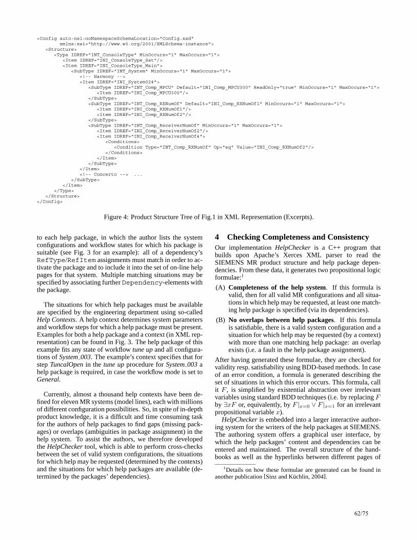
<Config auto-ns1:noNamespaceSchemaLocation="Config.xsd"xmlns:xsi="http://www.w3.org/2001/XMLSchema-instance">
<Structure><Type IDREF="INT_ConsoleType" MinOccurs="1" MaxOccurs="1">
<Item IDREF="INI_ConsoleType_Sat"/><Item IDREF="INI_ConsoleType_Main">
<SubType IDREF="INT_System" MinOccurs="1" MaxOccurs="1"><!-- Harmony --><Item IDREF="INI_System024">
<SubType IDREF="INT_Comp_MPCU" Default="INI_Comp_MPCU300" ReadOnly="true" MinOccurs="1" MaxOccurs="1"><Item IDREF="INI_Comp_MPCU300"/>
</SubType><SubType IDREF="INT_Comp_RXNumOf" Default="INI_Comp_RXNumOf1" MinOccurs="1" MaxOccurs="1">
<Item IDREF="INI_Comp_RXNumOf1"/><Item IDREF="INI_Comp_RXNumOf2"/>
</SubType><SubType IDREF="INT_Comp_ReceiverNumOf" MinOccurs="1" MaxOccurs="1">
<Item IDREF="INI_Comp_ReceiverNumOf2"/><Item IDREF="INI_Comp_ReceiverNumOf4">
<Conditions><Condition Type="INT_Comp_RXNumOf" Op="eq" Value="INI_Comp_RXNumOf2"/>
</Conditions></Item>
</SubType></Item><!-- Concerto --> ...
</SubType></Item>
</Type></Structure>
</Config>
Figure 4: Product Structure Tree of Fig.1 in XML Representation (Excerpts).
to each help package, in which the author lists the systemconfigurations and workflow states for which his package issuitable (see Fig. 3 for an example): all of a dependency’sRefType/RefItem assignments must match in order to ac-tivate the package and to include it into the set of on-line helppages for that system. Multiple matching situations may bespecified by associating further Dependency-elements withthe package.
The situations for which help packages must be availableare specified by the engineering department using so-calledHelp Contexts. A help context determines system parametersand workflow steps for which a help package must be present.Examples for both a help package and a context (in XML rep-resentation) can be found in Fig. 3. The help package of thisexample fits any state of workflow tune up and all configura-tions of System 003. The example’s context specifies that forstep TuncalOpen in the tune up procedure for System 003 ahelp package is required, in case the workflow mode is set toGeneral.
Currently, almost a thousand help contexts have been de-fined for eleven MR systems (model lines), each with millionsof different configuration possibilities. So, in spite of in-depthproduct knowledge, it is a difficult and time consuming taskfor the authors of help packages to find gaps (missing pack-ages) or overlaps (ambiguities in package assignment) in thehelp system. To assist the authors, we therefore developedthe HelpChecker tool, which is able to perform cross-checksbetween the set of valid system configurations, the situationsfor which help may be requested (determined by the contexts)and the situations for which help packages are available (de-termined by the packages’ dependencies).
4 Checking Completeness and ConsistencyOur implementation HelpChecker is a C++ program thatbuilds upon Apache’s Xerces XML parser to read theSIEMENS MR product structure and help package depen-dencies. From these data, it generates two propositional logicformulae:1
(A) Completeness of the help system. If this formula isvalid, then for all valid MR configurations and all situa-tions in which help may be requested, at least one match-ing help package is specified (via its dependencies).
(B) No overlaps between help packages. If this formulais satisfiable, there is a valid system configuration and asituation for which help may be requested (by a context)with more than one matching help package: an overlapexists (i.e. a fault in the help package assignment).
After having generated these formulae, they are checked forvalidity resp. satisfiability using BDD-based methods. In caseof an error condition, a formula is generated describing theset of situations in which this error occurs. This formula, callit F , is simplified by existential abstraction over irrelevantvariables using standard BDD techniques (i.e. by replacing Fby ∃xF or, equivalently, by F |x=0 ∨ F |x=1 for an irrelevantpropositional variable x).
HelpChecker is embedded into a larger interactive author-ing system for the writers of the help packages at SIEMENS.The authoring system offers a graphical user interface, bywhich the help packages’ content and dependencies can beentered and maintained. The overall structure of the hand-books as well as the hyperlinks between different pages of
1Details on how these formulae are generated can be found inanother publication [Sinz and Kuchlin, 2004].
62/75

Figure 5: Graphical representation of the part of the XML-Schema that deals with the product structure.
the documentation are pre-specified by the technical depart-ment and cannot be altered by the help package authors. Thisalso means that there is no intra-page hypertext navigationthat is under control of the help checker. Versioning of prod-ucts and handbooks is supported by the underlying XML database schemas. In the authoring tool editors have to select aspecial version of the data they are working on, however. Thisalso means that help packages for a follow-up version of thedocumentation may only be copied from an older version, butthere is no way to specify (by constraints) that they are alsovalid for the new edition.
Production use of the system is just starting, thus we donot have user feedback yet, and can only report on manuallycreated test cases (that were generated by SIEMENS docu-mentation experts, though). These tests contained eleven ba-sic MR systems, 964 help contexts and twelve (dummy) helppackages. The BDDs reflecting test formulae (A) and (B)contained up to 9715 nodes and 458 variables (with interme-diate BDD sizes during formula generation of over 100,000nodes).2 A complete check of our experimental XML help—including computation of error situations—took 6.96 sec-onds. The input data we used already contain the com-plete configuration structure for all of SIEMENS’ current MRmodel lines. However, the number of help packages is muchlower than what we expect during production use.
5 ConclusionIn this paper we have shown that individually configured ser-vice handbooks are feasible. By using a propositional logicencoding for both system configurations and the assignmentof handbook chapters (help packages) to product instances,we were able to employ advanced Boolean logic techniques(like BDDs). Those turned out to have enough potential tohandle the problems brought up by our completeness and con-sistency checks. Although we have demonstrated the feasi-bility of our method only for the MR systems of SIEMENS
2We have also conducted experiments using a SAT-Solver in-stead of the BDD package, and obtained very promising results.
Medical Solutions, we suppose that the presented techniquesare also usable for other complex products. More generally,we expect that a wide range of cross-checks between XMLdocuments can be computed efficiently using propositionallogic techniques.
References[Kuchlin and Sinz, 2000] W. Kuchlin and C. Sinz. Prov-
ing consistency assertions for automotive product datamanagement. J. Automated Reasoning, 24(1–2):145–163,February 2000.
[McGuiness and Wright, 1998] D.L. McGuiness and J.R.Wright. Conceptual modelling for configuration: A de-scription logic-based approach. AI EDAM, 12(4):333–344,1998.
[Mittal and Frayman, 1989] S. Mittal and F. Frayman. To-wards a generic model of configuration tasks. In Proc. ofthe 11th Intl. Joint Conf. on Artificial Intelligence, pages1395–1401, Detroit, MI, August 1989.
[Sabin and Weigel, 1998] D. Sabin and R. Weigel. Productconfiguration frameworks – a survey. IEEE Intelligent Sys-tems, 13(4):42–49, July/August 1998.
[Sinz and Kuchlin, 2004] Carsten Sinz and WolfgangKuchlin. Verifying the on-line help system of SIEMENSmagnetic resonance tomographs. In Proc. of the 6th Intl.Conf. on Formal Engineering Methods (ICFEM’2004),pages 391–402, Seattle, WA, November 2004. Springer.
[Soininen et al., 1998] T. Soininen, J. Tiihonen, T. Mannisto,and R. Sulonen. Towards a general ontology of configura-tion. AI EDAM, 12(4):357–372, 1998.
[XMLSchema, 2001] XML Schema Parts 0–2: Primer,Structures, Datatypes. W3C Recommendation, May 2001.
63/75

Reconfiguration – A Problem in Search of Solutions
Peter ManhartDaimlerChrysler AG
Research and Technology, REI/SP [email protected]
AbstractMany practical configuration problems are wellunderstood in theory and solved in practice by ex-isting product configurators. Yet, this does not ap-ply to the reconfiguration of existing complexproducts: here, there exist neither theories nor sys-tems that can deal with problems of realistic size. In this paper we describe a reconfiguration taskthat originates in the complex nature of electric, electronic, and software components of vehicles.From this, we derive research questions in search of solutions.
1 IntroductionReconfiguration is a serious challenge in industry and atleast for complex products it is so far not solved in a feasi-ble manner. This paper does not present possible solutionsbut aims at motivating for further research and develope-ment efforts by presenting the application area vehicles.Research on the product configuration domain is based onthe notion of a configurable product: a product individual ofa configurable product can be adapted to the requirementsof a particular customer order. The possibilities for adaptingthe configurable product are predefined in a configurationmodel that explicitly and declaratively describes the set oflegal product individuals. A specification of a product indi-vidual – a configuration - is produced in the configurationtask based on the configuration model and a set of customerrequirements. Efficient knowledge-based information sys-tems - product configurators - have become an importantand successful application of artificial intelligence tech-niques for companies selling products adapted to customerneeds [(Faltings, B., Freuder, E. C. 1998)(Soininen, T.,Stumptner, M., 2003)].
Reconfiguration on the other hand is an important task ofafter-sales. In reconfiguration, an existing product individ-ual is modified to meet new requirements (Männistö et. al.1999). Reconfiguration has always been a challenge, but theincreased complexity and variability of electronic controlunits (ECU), as well as the virtual nature of their softwareand parameters has turned reconfiguration into a key issuein after-sales.
ECUs and software have various advantages. Thus most ofthe innovations of present vehicles, for example, automaticbrake systems, come in conjunction with an electronic con-trol unit and software. In vehicles ECUs and embedded soft-ware are strongly interwoven with the mechanical, electric, and electronic subsystems. But not only has a comparativelysimple realization of complex add-on functionality in-creased the use of information technology in vehicles, thepossibility to shift variability from hardware to softwarealso make ECUs the solution of choice for engineers andmanufacturers.But are all of these advantages for nothing? State-of-the-artsystem development processes and system architecturesinduce a severe configuration complexity in products. Theresulting challenges can be handled maturely in develop-ment by configuration management systems and in manu-facturing by product configurators.But somewhere along the way, a vehicle comes to a dealer’sworkshop and the owner needs a modification of a historicalconfiguration that involves changes to the systems consist-ing of mechanical parts, ECUs, and software. Then the cor-responding reconfiguration tasks have to be solved for thesafety-critical system “vehicle” and, as our research hasshown, reconfiguration is more complex than configuration.
In the next sections we will introduce our business ob-ject and the underlying markets rules, describe practical reconfiguration use cases, and motivate why reconfigurationis more complex than regular configuration issues.
2 The Business of Buses In this section, we sketch the business environment of pre-mium buses and illustrate what such buses look like from anarchitectural perspective.
2.1 The Business Environment Customers buying high end buses do not buy off the shelf.Their own varying business models result in a high degreeof individualization. Additionally, bus purchasers frequentlyimpose customer-specific functionalities even in late manu-facturing phases.Especially the after-sales business is challenging. A bus owner recognizing a useful new function in a newly boughtbus will often demand an upgrade of a five-year-old model
64/75

from the dealership. Hence configurations that were never apossible production state evolve.Also, a bus can interact intensively with its environment bysending signals to its stopping places, reporting to the cen-tral public transportation computers, and controlling auto-mated fueling stations. These third-party systems are notbased on public standards but create a need for developmentof custom hardware and software interfaces.All of these issues not only increase time pressure for the development of customer-specific embedded software butalso boost variation dramatically. Additionally they have animpact on the system architecture and the software process.However, before we can address the concrete reconfigura-tion problem of buses as by these requirements, we need abasic understanding of the technical architecture of the sys-tem.
2.2 Electric Electronic (EE) Architecture of a Bus Software-based functions in buses either reside in pro-grammed controller units or are uploaded to programmablecontrollers.A modern bus contains between four and six programmablecontroller units (see FPS in Figure 1). Controllers are con-nected by a low speed vehicle CAN (controller area net-work) and offer the following functions:1. Gateway: They are communication gateways to pro-
grammed controllers at the aggregate level, e.g., to theelectronic brake control unit.
2. IO: They convert hardware signals to CAN messages.3. Bus functions: On the basis of a real-time operating
system, they compute and control bus-specific func-tionality such as control of doors, climate, or au-dio/video equipment.
Figure 1: EE Architecture of a Premium Bus Customer-specific software functionality is invariably im-plemented in the form of bus functions, in our case takingthe form of so-called function plans (FUPs) according toIEC1131-3. When a customer requests a special functional-ity, a decision is made as to whether this will be fully or partially implemented in software. In this case, the engineer-ing department has to produce one or more new functionplans within time and quality constraints.
The conditions of engineering embedded software for high-end buses differ from those in many other automotive soft-ware engineering processes:1. There is a higher degree of customer-specific function-
ality combined with greater time pressure and the ne-cessity to deliver very high quality.
2. The resulting non-standard equipment, functions, orparameter sets are implemented by integrating differentshares of third-party and OEM components.
3. Software for complex electric or electronic functionsoften runs on programmable computer controllers. Insuch a software environment, change seems easy from the customer's point of view.
4. Customers buying buses make a major investment(> 500,000 euros). They demand top quality. When newrequirements come to mind, they expect them to beconsidered.
All of these issues increase product variation and, as a re-sult, reconfiguration complexity significantly and is costlyto manage.
2 The After-Sales Retrofitting Processesand the Reconfiguration Task
In the shop, the complexity and variability sketched in the last section accumulates to severe reconfiguration problems. We have two main business cases in mind:1. Replacement of existing systems
Recall actions Spare and wear parts
2. Enhancement of existing functionalityUsing existing componentsEngineering new customer-specific functions
Thus far, changing an existing complex system is rather areengineering than a configuration task. In order to solvethis problem more systematically or to more easily automatethe retrofitting process, we have to become able to solve the reconfiguration task that can be defined informally as fol-lows:
IBIS
Onboard -Diagnosis
CAN-Bus "IES"
RET = Retarder ControlRET = Retarder Control
NR = ElektronicNiveau ControlNR = ElektronicNiveau ControlFPS = FlexibleProgrammableControlFPS = FlexibleProgrammableControlFR = Drive ControlFR = Drive ControlBS = ElektronicBreak ControlBS = ElektronicBreak ControlAM = Axle Modul (Breaks)AM = Axle Modul (Breaks)
ZHE = AdditionalHeatingZHE = AdditionalHeating
HLK = ClimateControlHLK = ClimateControl
IBIS = IntegratedBoard Information SystemIBIS = IntegratedBoard Information SystemMR = EngineControlMR = EngineControlMTS = ModularDoorControlSystemMTS = ModularDoorControlSystem
1 - 5 = Mirror Memories FPS1 - 5 = Mirror Memories FPS
BS
FR
RET
NR
AM
MR
CAN-Bus "COM"
MTSDoor1
Tür2
HLK1
HLK4
CAN-Bus „ Vehicle"
FPS1 FPS 2
IBIS
FPS 3 FPS 41 2 35
K-Line
ZHE
Diagnosis
Upload
CA
N-B
us
"DM
UX
"
Multi -media
MC-Net
HLK3HLK3
HLK2HLK2
FPS 54
ZV/EDW
ZV/EDW= Lock Control, Burglar ProtectionSystemFPS1= FlexibleProgrammableControl(Module1)FPS1= FlexibleProgrammableControl(Module1)
A reconfiguration task is solved if a starting configura-tion is transformed into a target configuration includingall reconfiguration constraints.The reconfiguration constraints include the following:
The use case, e.g., replacing a part by a successorCorrectness with respect to functional and non-functional requirements: basically, the new configu-ration should have a highest possible intersectionwith the requirements that is technically possible and affordableMinimality with respect to changing behavior and configuration items: no unnecessary part should bereplaced and a minimum of behavior should bechanged, if necessary at all
While these definitions are far from being formal defini-tions, they cover numerous practical requirements of after-sales retrofitting processes.
65/75

In the next section, we focus on the reasons why reconfigu-ration is more complex than configuration.
3 The Cause of the Problem When traditional development engineers think about chang-ing a configuration item their focus often lies on production.Here it is only necessary to model dependencies with re-spect to the currently released items. For reconfiguration inafter-sales knowledge of dependencies to all historical ver-sions of configurations items are potentially essential. Thenecessity of deriving and modeling these dependenciesmakes reconfiguration a significant more complex task thanproduction-oriented configuration.In Figure 2 the dashed line represents a dependency relation:Part 3, revision 2 needs part 1, revision 2 in order to func-tion properly. For developmentpurposes, it is not necessary to make these relations explicit as long as the new revision or variantof an existing part interworks with the other configuration items thatare currently used. Also, produc-tion does not need them as they are able to switch their productionlines at a certain point in time fromthe predecessor to the new ver-sions. Basically, rule-based con-figuration approaches and configu-rators (Sinz, Kaiser Küchlein,2003) reflect this mindset. Thusknowledge about interdependen-cies is often represented in a top-down constructive way: ifa certain logical expression over requirement predicatesholds true, then a certain set of configuration items is addedto the configuration. Transversal dependencies betweencomponents are not necessary for production-oriented con-figuration and are therefore not modeled.Figure 3 sketches the situation from the after-sales perspec-
tive. The solid bold line represents the production configura-tion that enters the workshop, for example, with a defective ECU labeled P3/0. The currently available spare part is P3/2(part 3, revision 2). The reconfiguration task includes an-
swering the following question: What is a minimal correct target configuration that contains P3/2 instead of the defectP3/0?In addition to the revision links, Figure 3 indicates thetransversal dependencies d1, d2, and d3. Clearly, these haveto be considered if the reconfiguration task is to succeedboth correctly and minimally. In this example, the minimaland correct target configuration is represented by the dashedbold line. In addition to upgrading P3/0 to P3/2, d1 calls foran upgrade of P1/0 to P1/2, and via d3 this upgrade transi-tively requires upgrading P4/0 to P4/1. Together with thou-sands of other parts of the configuration, P2/0 can remainunchanged. In order to find this solution, all the dependen-cies (and non-dependencies) have to be considered as wellas the corresponding compatibility relations. Unfortunatelythese dependencies are usually un-documented for a numberof reasons. To cite just a few,P1/2
P2/1
P3/1
P3/2
P4/3
d1
Figure 2: Developer View
they are complex to derive,they are large in size, they are not necessary to introduce product innovations.
However,they are also not covered by systematic approaches orconfigurators.
These are some of the reasons why reconfiguration of com-plex systems today is rather a reengineering than a configu-ration task. Whereas the first three issues are problem-immanent characteristics that come with complex systems,the last one can be recognized as a set of research chal-lenges:
How to enhance the production orientation by after-sales oriented thinking?What requirements engineering processes and productdevelopment processes lead to more reconfigurableproducts?What are adequate reconfiguration models?Which configurator approaches fit best for reconfigura-tion?P1/0 P1/1 P1/2
P2/0 P2/1
P3/0 P3/1 P3/2
P4/0 P4/1 P4/2 P4/3
d1
d2
d3
Figure 3: Aftersales View
These questions can be summarized to the following keyquestion:
How can we systematically derive and documentproduct transversal dependencies in practice so that re-configuration can be largely automated by product re-configurators?Here the term “in practice” means that simplifying sug-gestions such as “document all dependencies and thealgorithm will work” are not considered to be useful.Instead, the engineer needs methods and approachesthat prune the search space of configuration items to a manageable size.
Interestingly these reconfiguration challenges also exist inpure mechanical systems and are largely handled by theworkshops. For example, an instrument panel bracket mightbe “enhanced” by an additional mounting hole, which is notused when the part is initially assembled. After some time, anew, additional part is attached at the mounting position.
66/75

When an older vehicle – lacking the mounting hole - comes to the workshop and is to be enhanced by new part, it is not possible to do this as no adequate mounting position exists. Problems like this are frequently solved in the shop, so what are differences to the EE world? Basically, drilling a new hole or even re-cabeling is on the re-engineering level of a well-trained mechanic or electrician, whereas ECUs and - even worse - software and parameters within ECUs are dif-ficult or impossible to access. Here, we can link back to the introduction: in recent years, an increasing amount of the customer benefit of vehicles has been implemented in electric and electronic components. In particular, software-based functions add an ever higher amount of customer value to our vehicles. Additionally creation and management of variability was improved by introducing parameters in ECUs, at least for production. But it turned after-sales a much more engineering-oriented than workshop-oriented work field. From a reconfiguration perspective, this implies that the capability of reconfiguring complex software-based systems systematically will become more and more mandatory if we do not want to bind more and more development and after-sales capacities by reengineering complex systems.
4 Related Work As far as we know, science has so far recognized reconfigu-ration more or less as an interesting supplementary question. For example, some configuration workshop papers of the AAAI, ECAJ, and IJCAI explicitly mention the problem. But also many papers don’t even realize the challenge to change an existing system instead of configuring a new one.
One work that explicitly addresses the task is the doctoral thesis of Männistö (Männistö 2000). Here reconfiguration is modelled by reconfiguration operations. We could classify this as an “explicit upgrade package” approach in contrast to a “full reconfiguration model”. Kreuz and Roller [Kreuz and Roller, 1999] describe the use of a reconfiguration system and explicitly address the problem of long term knowledge maintenance. The doctoral thesis of Heinisch [Heinisch, 2004] describes a configuration model for vehicles that al-lows for reprogramming ECUs. Other publications do not aim at reconfiguration directly but possibly contribute to it: Is “retraction” in description logic based approaches (McGuinnes and Wright 1998) a useful full reconfiguration model? Does conceptual modeling (McGuinnes and Wright 1998) deliver a full reconfiguration model that is practically relevant? Can design-specifications and interactive configuration (Feldkamp, Heinrich, Meyer-Gramann, 1998) be also a solution for re-configuration in addition to re-use? How much and what kind of additional modelling is necessary to formally validate reconfigured configurations compared instead of validating only (Sinz, Kaiser Küchlein, 2003) production configurations? Can constraint solving heuristics (Hulubai, Freuder, Wallace, 2003) contribute to the problem of finding not only correct, but also optimal reconfigurations? The literature delivers many potential contributions to reconfiguration but no ready-to-use approach.
Yet the production oriented view seems to be engrained deeply in the mindset of all parties concerned: numerous configuration publications do not acknowledge the problem at all. The perception of engineers and manufacturing staff in practice, even those having years of experience with con-figuration, is not better. To make a long story short: up to now we find no theory, no methods, and no systems that can handle reconfiguration problems of a practical size. Hence, the goal of this paper is not to provide solutions for reconfiguration but to re-introduce the importance of the topic from practical business cases in after-sales, to provide a well founded basis for discussion, to review existing work, and to motivate for future research.
5 Bibliography (Faltings, B., Freuder, E. C. 1998): Special Issue on Con-
figuration. IEEE Intelligent Systems 14(4) 1998 29-85
(Feldkamp, Heinrich, Meyer-Gramann, 1998) SyDeR - System design for reusability, Artifical Intelligence for Engineering Design (1998), Special issue on configura-tion, Cambridge University Press.
(Heinisch 2004) Konfigurationsmodell und Architektur für eine automatisierte Software-Aktualisierung von Steuer-geräten im Automobil, PhD thesis. Eberhard-Karls-Universität zu Tübingen
(Hulubai, Freuder, Wallace, 2003) The Goldilocks problem, Artifical Intelligence for Engineering Design, Analysis and Manufacturing (2003), Special issue on configura-tion, Cambridge University Press.
(Kreuz and Roller, 1999) Kreutz, Ingo, and Dieter Roller. 1999. “Knowledge Growing Old in Reconfiguration Context”. In Configuration Papers from the AAAI Workshop, AAAI Technical Report WS99, 05. AAAI Press. p. 54–58.
(Männistö, 2000) Männistö, Tomi. 2000. A conceptual modelling approach to product families and their evolu-tion. PhD thesis. Helsinki University of Technology.
(Männistö, T. et. al., 1999) Framework and Conceptual Model for Reconfiguration. In Configuration Papers from the AAAI Workshop, pp. 59-64. AAAI Technical Report WS-99-05. AAAI Press, 1999.
(McGuinnes and Wright 1998) Conceptual modelling for configuration: A description logic-based approach, Arti-fical Intelligence for Engineering Design (1998), Special issue on configuration, Cambridge University Press.
(Sinz, Kaiser Küchlein, 2003) Formal methods for the vali-dation of automotive product configuration data, Artifi-cal Intelligence for Engineering Design, Analysis and Manufacturing (2003), Special issue on configuration, Cambridge University Press.
(Soininen, T., Stumptner, M., 2003) Introduction to Special Issue on Configuration. Artificial Intelligence for Engi-neering Design, Analysis and Manufacturing 17(1-2) (2003) 1-2
67/75

Abstract SAP provides a configurator engine as part of its business software offering already for over a dec-ade. During this time integration issues have proven overall more challenging than the issue of configurator technology itself. The “variant con-figurator” inside the SAP R3 system (one of the leading integrated business software suites world-wide) is in active use by more than 1500 SAP cus-tomers. However, the growing importance of sales channels like the internet or field sales pose new challenges in that “end customers” are more di-rectly involved in the configuration process. This leads to different expectations with regard to ease of use and cost of implementation.
1 Introduction This paper summarizes selected experiences with product configuration functionality in SAP’s business software suite from a technical, configurator oriented perspective. It is not meant as a guide to respective product offerings at SAP.
A detailed presentation of the functionality and modeling concepts at the heart of configuration in SAP is out of scope, but is partially given in [Haag, 1998]. General docu-mentation on product configuration at SAP can be found at: http://help.sap.com1.
1.1 Configurable Products2
Product business data typically consists of a product key (id) and a set of properties or attributes. For example, when ordering a box of crayons, a material number uniquely iden-tifies the product itself. A textual and pictorial description is associated with the box for depiction in a catalog. The size
1 For the variant configurator look in tab "Documentation my-SAP ERP" in area SAP ERP Central Component > Logistics > Logistics General (LO) > Variant Configuration (LO-VC). For the IPC (Internet Pricing and Configuration) look in tab "MySAP Business Suite in area SAP Customer Relationship Mgmt. > CRM Enterprise > Enterprise Sales > Quotation and Order Management > Sales Order Processing (Configure to Order)).
2 The term product also refers to an immaterial offering such as a service.
and weight of the box (as well as lot sizes) is needed to process shipment.
For configurable products additional properties describe the individual item being sold. For example, a car being manufactured to a specific customer order will often contain a combination of features that are unique to that particular order. Although its serial number is a unique identifier, it is not efficient to pre-assign a product id to each feasible com-bination of features. In the sequel, the term characteristicrefers to a property of a configurable product that describes individually configured items. (Elsewhere, the terms prop-erty, attribute, and characteristic are often used inter-changeably).
A configurable product can be complex. It can have a very large number of characteristics and it can be composed of parts that are themselves configurable products (nested configuration).
1.2 Product Configurator A product configurator is a software function that aids a business application in handling configurable products. The primary task of a product configurator is to check that a given value assignment for the characteristics of a product is consistent and complete in the context of the business appli-cation. In the case of nested configuration the consistency and completeness of the determined set of parts must also be verified. A further task is to guide an interactive user through the configuration process, i.e. inform them of the valid choices at each step.
Product configurators are often implemented in a project specific way, either from scratch or on top of an existing configurator engine. Like all software development such an endeavor often proves very costly to sustain.
1.3 Configuration in SAP Business Software As a vendor of standard business software SAP provides
integrated product configuration functionality as part of its business software offering, both inside and outside back-office applications.
Back-Office IntegrationThe SAP R3 system (an integrated suite of business applica-tions) includes the variant configurator. Its main focus is on back-office applications (business documents being main-
“Dealing” with Configurable Products in the SAP Business Suite
Albert Haag SAP AG
Research & Breakthrough Innovation Neurottstrasse 16, 69190 Walldorf, Germany
68/75

tained in-house by employees of the business). The variant configurator is integrated into the relevant business applica-tions, particularly sales and distribution.
Widespread use of the variant configurator began in 1994/1995. Currently, an estimated more than 1500 SAP customers are actively using it.
Channel Enabling SAP also provides a Java-based configurator called IPC (Internet Pricing and Configuration), primarily to enable sales channels outside the back-office. The IPC not only addresses Internet sales channels (both B2B and B2C), but also call centers, field sales, etc.
Since orders are usually ultimately fed into a back-end (R3) system, compatibility with the variant configurator must be maintained as far as possible in standard application scenarios.
An “advanced mode” that sacrifices compatibility for more configurator functionality is available for custom pro-jects where standard integration is not required. This is used in particular for configuration of complex systems and net-works.
Productive use of the IPC began in 1998/1999. It is not yet used quite as pervasively as the variant configurator. However, potentially, every variant configurator customer is also interested in channel enabling.
2 Types of Configuration Integration of product configuration in sales applications have shown that it is useful to distinguish the following three types of configuration:
High-level configuration
Manufacturing completion
Low-level configuration
High-level configuration is primarily interactive configu-ration. A user constructs a consistent and complete configu-ration as part of a business document (e.g. sales order). The set of characteristics allows pricing, but is not necessarily extensive enough for direct derivation of manufacturing/ procurement information including detailed costing and availability.
Manufacturing completion is a non-interactive process. The configurator checks a pre-defined configuration (result-ing from either high-level configuration or an external or-der-entry tool) for consistency and completeness. It also expands the configuration to a larger set of characteristics. This expansion is needed to drive the manufacturing proc-esses, as well as determine availability of parts, costing, etc. It can depend on the production plant chosen.
Low-level configuration is non-interactive, programmatic process. The (expanded) characteristics of a single compo-nent drive the selection of parts in the manufacturing proc-ess and the configuration of routings etc.
The variant configurator and the IPC deal with high-level configuration and manufacturing completion. It has proven beneficial to provide a dedicated implementation for low-level configuration.
3 Selected Aspects of Integration Most customers value end-to-end integration much more than enhanced configurator functionality. If R3 is the back-end business system, this means that any front-end configu-rator is best compatible with the variant configurator.
Externalized Configuration The result of a (high-level) configuration must be stored with the business document (sales order). This configuration is used in several ways:
Displayed/ printed as part of sales order
Re-loaded by the configurator for further changes
Read as input to low-level configuration
May be modified directly on shop floor in extreme cases (“on the fly substitution of features”)
Synchronization of Product Model with Master Data Large parts of the product model used by the configurator must be in synch with master data used by various business processes. Particularly, high-level configuration and manu-facturing completion must produce results that are intelligi-ble to low-level configuration. Also, the space of legal con-figurations should match what can be (reasonably) manufac-tured.
Forecasting may benefit by being able to introspect the product model. For example, if the model dictates that all red cars have black seats, any forecast on read cars will also apply to black seats (simplistic case).
The variant configurator directly uses the R3 master data as its product model repository. The IPC automatically ex-tracts product models from the R3 master data. However, many other configurators require product models expressed in their own modeling language. Keeping such product models in synch with the master data can be a costly exer-cise. Experience has shown that this cost is often prohibitive if the synchronization is manual.
Pricing, Costing, and Availability Pricing should be possible solely based on the master data and parameters provided by the business document (such as customer and contract data). In contrast, costing and avail-ability can entail a full simulation of the logistic processes. This requires all levels of the configuration actually to be carried out.
5 Managing the Cost of Implementing Prod-uct Configuration
Due to the many sources of additional complexity, dealing with configurable products can be costly compared to deal-ing with non-configurable products even when using an integrated environment such as provided by SAP. It is one major objective to reduce and better control this cost. Some factors that directly influence this cost:
Complexity of the product and its model Power of the maintenance and test environment
69/75

Implementation platform (performance, stability, and scalability)
5.1 Product and Product Model Complexity Experience has shown that it is useful to distinguish at least the following three levels of product complexity:
Simple products with a small number of characteristics (around 50)
Nested products. Products that involve configuring components. Nesting can go several levels deep. Al-together there can be thousands of characteristics.
Systems/ network configuration – there can be tens of thousands of items in such a solution each with many characteristics
The complexity of the product influences not only the performance of configuration and the complexity of the user interface, but also the complexity of integration with the business processes. In R3 there is fairly complete standard integration with sales and logistics processes for simple products and nested configurable products. Integration for systems configuration has been harder to standardize. This is usually done on a project basis using the “advanced mode” in the IPC.
Keeping the product model (including constraints) as simple as possible is a substantial part of controlling the cost of implementing configuration. Models for products that are essentially similar from the business point of view can differ widely in their complexity. Unwarranted complexity often ensues because the modeler is trying for perfection beyond the actual business need.
Currently good modeling is achieved by following “best practices” established by experienced modelers. An idea for further improvement is to remove sources of complexity by tailoring the modeling environment to suit the particular business need and/or product complexity. Examples of this at different levels might be:
Allow simple products only (disallow components) Disallow multiple inheritance in classifying prod-ucts Disallow constraints between components in a nested product, except for ancestor/ descendant re-lations.
5.2 Modeling and Test Environment At a certain level of abstraction product modeling can be seen as software development. Hence, a modeling environ-ment should resemble a modern software IDE (Integrated Development Environment). Some key features are:
Allow overview and navigation within the model Allow immediate simulation of the model using the configurator Support for “best practices” as discussed above.
One idea for further improvement is to provide a direct analysis of performance and integration implications based on the complexity of the constraints and estimated size of ensuing configurations. Also, support for customizing the
user interface is needed. However, this is usually done by persons distinct from the modeling, so it is best provided separately.
To support testing, the configurator should provide profil-ing, tracing and logging facilities. The IPC also foresees debugging facilities for the evaluation of constraints. How-ever, this feature seems not to have been needed to date.
5.3 Implementation Platform The variant configurator runs within the R3 system and thus benefits from the performance, stability, and scalability of the underlying SAP server technology as well as being able to use its central repository. The IPC being implemented in Java has hitherto not been able to make direct use of this platform. However, it is currently also being moved to the SAP technology stack. This move is expected to yield a substantial reduction in cost in installing, administering and running the IPC.
6 Recent Challenges and Current Work Non-professional end-users require better support during interactive configuration. Mostly this means improvements to the user interface. To some extent the core configurator functionality must be extended. Some recent improvements to the core configurator include:
Calculation of the set of valid values for a characteris-tic assuming the current value were not set
Information about how to resolve conflicts and to make excluded choices available
More rigorous handling of conflicting defaults
By chance, all of the above involve improving or making better use of the TMS (Truth Maintenance System) which is a part of the IPC. For a description of the role of defaults and of the TMS in the SAP configurators see [Haag, 1998] .
6.1 Calculating “Dynamic User Domains” One very basic function of a configurator is to calculate the set of available choices at each step in an interactive con-figuration. If a value for a characteristic has been set (by the user or as a default) the user needs to know what values would be available for that characteristic to replace the cur-rent choice. This set of is called the dynamic user domain at SAP.
A basic means (used by some customers for some time) to address this is to perform the following steps in the back-ground each time a dynamic user domain is to be displayed:
Delete the current value and reconfigure
Cache the resulting domain for the characteristic
Reset the value and reconfigure. Display the cached domain as the set of available values to the user
Ideally this procedure needs to be applied only on de-mand for one characteristic at a time. However, in web sce-narios all currently displayable characteristics need to be processed on each round trip (to avoid additional round
70/75

trips). Thus, the above approach works for simple products, but has proved to have performance problems for the other cases. The improvement is to emulate this procedure inter-nally:
Simulate retracting user and default justifications for the current value in the TMS. Do not actually delete anything from the internal configuration state
Perform some additional constraint propagation as war-ranted (only a fraction of the effort needed to recon-figure after deletion of the value)
Cache the resulting domain for the characteristic
Reinstate any justifications that were retracted in the first step (no further constraint propagation required)
Experiences so far suggest that this performs also for nested products and systems configuration3. However, it cannot take into account the effect of values that were set by procedural means because justifications are incomplete in this case. In other words a purely constraint-based model is works best.
Note that the calculation described above could be gener-alized to what-if type queries. However, handling these would require conceptual extensions to the user interface.
6.2 Guided Resolution of Inconsistencies For some time the TMS in the IPC has been extended to perform an ATMS label calculation4 on demand. The TMS calculates minimal sets of user choices and/ or defaults that support inconsistency, called nogoods.
In order to resolve inconsistency one user input/ default needs to be retracted for each nogood. The user interface can guide the user to choose one user input/ default for re-traction from a list. Each entry in the list will be in at least one nogood. Entries that are in multiple nogoods are pre-sented more prominently, as this will handle multiple nogoods in one step. The procedure must be repeated until all nogoods have been handled.
The same procedure might also be used to allow selecting choices that have been excluded by the constraints. In this case the newly chosen value would not be offered for retrac-tion. An explanation of what the choosing the excluded value entails could be obtained by calculating the ATMS label pertaining to the exclusion.
6.3 Handling of Defaults During Configuration it can happen that inconsistency is derived and is founded on one or more values originally set as defaults. Currently there is an algorithm in place that bumps defaults in such situations. However, the exact effect
3 The dynamic user domain calculation can be turned off in the event performance problems are encountered
4 For a conceptual overview of an ATMS (Assumption Based Truth Maintenance System) see [DeKleer, 1986]. The details of how the TMS in the IPC relates user choices and justifications to assumptions have not yet been published. Ideas put forth in [Haag, 1998] have since been carried further.
of this bumping in large models is not transparent to the modelers and thus hard to manage and test. Also it has proven difficult to reinstate these defaults when the cause of their having been bumped is retracted.
For this reason there is work in progress to perform this bumping in a more rigorous manner and to reinstate bumped defaults when warranted based on their membership in nogoods.
7 AcknowledgementsMany colleagues (both in development and consulting), customers, and third parties have all contributed to devel-opments and improvements of product configuration at SAP for over a decade. The following website is maintained by a group representative of this effort: http://www.configuration-workgroup.com/
References [DeKleer, 1986] J. De Kleer. An assumption based truth
maintenance system. Artificial Intelligence, 28:127--162, 1986
[Haag, 1998] Albert Haag, Sales Configuration in Business Processes. IEEE Intelligent Systems 13(4): 78-85 (1998).
71/75

Abstract
Business processes for sales and distribution were highly improved by the application of configu-rators. As more companies employ configurators, the sales process with configurators is not innova-tive any more, but becomes standardized. A com-pany may again come up with a business processinnovation if it launches radically innovativeconfigurator features.
1 Innovation and standardization
In his book [Moore, 2002] G. Moore describes the life-cyclestages of services and business processes.
• Stage 1: Invention
• Stage 2: Innovation
• Stage 3: Standardization
• Stage 4: CommoditizationIn the innovation stage, companies design a service in a
way that yields competitive advantage through differen-tiation. When a service is successful, it is often copied by competitors and its basic idea is used widely. The transition from innovation to standardization also means that the key success factor changes from differentiation (i.e. features) to productivity (i.e. efficiency and price). A service movesfrom the standardization to the commoditization stage when many suppliers offer the same service.
2 Current situation of configurators
Ten years ago the business processes with configuratorswere in the innovation stage. Only few configurator toolswere available, and few were employed in practical appli-cations. Differentiation of business processes by theapplication of a configurator was important.
Configurators are now widely accepted. Their usefulness was proven by many productive applications. Now the busi-ness processes with configurators are in the standardizationstage. The configurator tools may be innovative, but thesales processes are standardized (in a sense) as most salesprocesses employ configurators.
The components of a configurator application are relevant in different stages of the life-cycle of the sales process (D = distinguishing factor for companies that use a configurator).
Stage Inven-tion
Inno-vation
Standardi-zation
Commodi-tization
Configuratorkernel D D
Requirementsengineering
D D D
Interfaces(files, UI)
D D
If radically innovative configurator features are devel-oped and deployed, a company may again come up with an innovative business process and differentiate itself from the competitors. If the features of configurators broadly remainas they are, the business process with configurators willinevitably move from the standardization to thecommoditization stage. There only cost counts.
3 Summary and conclusions
The features of the kernel itself become less important asconfigurator applications become established. The require-ments engineering is a key success factor in all stages that are relevant for practical use. The interfaces become more important in the stages where productivity is the key driverfor competitive advantage.
Altogether configurator applications are successful if they support the customers in being more competitive. Research-ers and developers want to work on innovative features.However, the competitive advantage for the customers may require a focus on productivity, i.e. increased efficiency forthe customer’s processes.
References
[Moore, 2002] Geoffrey A. Moore. Living on the FaultLine, Revised Edition: Managing for Shareholder Value in Any Economy. HarperCollins Publishers, Inc., NewYork, 2002.
Configurators in innovative or standardized business processes
Gerhard FleischanderlSiemens AG Österreich
Program and System EngineeringErdberger Laende 26, A-1030 Vienna, Austria
72/75

MCml2
Jirı Vyskocil, Martin Trcka, Libor Denner, Petr SvabCharles University in Prague, Faculty of Mathematics and Physics
Malostranske namestı 2/25, 118 00 Praha 1, Czech [email protected]
AbstractWe decribe the MCml2 system which generates ap-plications for configuration. Typical usage of thissystem is configuration of the Linux kernel, how-ever it is not restricted to any platform, program-ming language, user interface or configuration task.
1 Introduction1.1 MotivationImagine the following situation: you have just bought a newexternal CD-Writer HP 8230e and you want to use it underLinux operating system. First you probably need to add sup-port for this drive to Linux kernel. But Linux kernel config-uration is not easy, you must not forget to enable SCSI andUSB support, input core support, ISA- and PCI-bus hardwaresupport, USB mass storage support and so on, otherwise yourCD-Writer will not work. Laic user usually has not sufficientknowledge and experience to find out, realize or even remem-ber such dependencies.
To make user’s work easier or even to make it possible to bedone we need some expert system, which can, on the basis ofknowledge acquired from Linux kernel specialist, solve thesebindings itself or with minimal assistance of user.
In the situation above, the user would need to know onlythe type of CD-Writer and the expert system would set up allconfiguration items necessary for work with this writer.
1.2 What does MCml2 do?MCml2 project generates applications, expert systems that al-low setting a configuration. A configuration is a set of con-figuration symbols that have its own type and value, that haveto conform to some rules and that have some dependencies.
MCml2 input is a file with declaration of symbols, rulesand dependencies written in CML2+ language [2]. This filerepresents knowledge base and is usually called CML2+ rule-base.
MCml2 output is an application that ”realizes” this input,i. e.
• allows setting of symbol values• checks and, in case of need, forces the validity of con-
figuration, in other words it watches over rules and de-pendencies
• automatic computes dependent values
• explains all configuration inconsistency to user
1.3 Features and Advantages of MCml2Generally, MCml2 implements CML2+ language [2] , whichis CML2 [3] with some extensions. CML2+ is a language fordescribing sets of variables (called symbols) and was devel-oped to be a tool for linux kernel configuration. It’s a descrip-tive language, not imperative. It means you only describewhat should be satisfied and some CML2+ engine reads itand performs it (all details about CML2+ can be found inCML2+ specification [2]). MCml2 will be - in a way - suchan engine. CML2+ is extended two value propositional logic.There are extensions such as arithmetic operations, tree statelogic, strings operations, etc.
The MCml2 system is not actually the final desired pro-gram that works with CML2+ description, but a generator ofall such programs. And by ’all’ we mean in all languages andall user-interfaces that we support now or in the future.
Here are some basic points concerning features and advan-tages of the MCml2 system:
• The MCml2 generator is written purely in C, so it couldbe compiled on wide range of architectures and operat-ing systems.
• MCml2 uses own extension of CML2 language that bet-ter fits needs of configuration systems than older CML1.It also supports UTF-8, so texts of configuration sym-bols are not limited to English only.
• MCml2 is able to generate code in several proceduralprogramming languages (at this time MCml2 supportsC and Java), so there is larger variety of programmersthat can extend final applications.
• Code generated by MCml2 is fast because it is optimizedjust for one purpose.
• Presentation part of final applications is strictly sepa-rated from the computing part; therefore it is not com-plicated to change the interface of applications.
• Various updates in wide range of future extensions areeasy to achieve.
The whole concept of MCml2 development has an idea ofuniversality. We don’t want CML2+ to be restricted only to
73/75

C-code and linux configuration. That’s why the result ap-plication needn’t be only in C, but in any other procedurallanguage (which is or will be supported). One of them is Javafor ensuring multiplatform usage and for possibility of web-configuring without downloading any application.
2 Project StructureThe basic project structure is clearly shown in the Projectdataflow graph.
Here you can see how the source code becomes the resultprogram of the final user. One can recognize four major steps:
• CML2+ compilation
• Metacode generation
• Meta to X compilation
• Linking with the desired User Interface
2.1 CML2+ CompilerThe raw text CML2+ data are compiled by CML2+ compiler.It is called from the generator and performs all lexical, syntaxand semantic analysis. It also generates tags to help texts andexpression strings and other data that are used by further andfinal parts.
For CML2+ debugging purposes it’s possible to make justa very fast CML2+ checker - the standalone compiler, whichis quite useful if you just want to check whether your rulebasechange is OK.
2.2 Metacode GeneratorThe data from semantic analysis are transformed to metalan-guage code. Metalanguage code [4] is high level Pascal-likeprocedural language.
This process runs separately, CML2+ formulae and datastructures are dynamically generated and the basic engine ismainly added as a static metalanguage code.
This is all performed with no Metalanguage in text form.It’s because all the Metalanguege stuff is passed in memory,and therefore it never occurs in non-parsed form.
2.3 Meta to X CompilationThe Metalanguage must be compiled into the target languageto be usable. That’s why the third part is the Meta to target-language compiler. For example only the Meta to C compila-tion is typically used for Unix kernel rulebase. Meta to Javawould be probably used mainly for web purposes.
This is a part of generator binary and it is called at the endaccording to the command-line options. After this step thewhole engine is generated in the target language.
2.4 Linking with the desired User InterfaceIn the final step comes the global makefile which links to-gether the generated engine and the prepared user interface.It could be one of the supported user interface or any otherthat communicates properly through intercode. It, of course,has to be in an appropriate language.
After this final link the standalone end-user application isbuilt and configuration may begin.
3 Applications and Similar ProjectsThe original idea of universal configuration tool is based onEric Raymond’s Linux configuration language CML2. It’sthe ancestral language of our CML2+ (which is CML2 withextensions). Gcml2 project is another challenge, but it againsolves only Linux kernel configuration problem. Compari-son of MCml2 and other projects is not simple because otherprojects have different orientation.
The presented system was tested on some versions of theLinux kernel and some other applications. It can be down-loaded from sourceforge site [1]. Many tests show that thisconfiguration tool in Linux kernel is faster for the end userthan any other existing configuration tool. Due to its versatil-ity it can be used for numerous other real world configurationtasks.
References[1] Homepage of project MCml2
http://cml2config.sourceforge.net/
[2] CML2+ language specificationhttp://cml2config.sourceforge.net/doc/doc-user-cml2plus.html
[3] Original CML2 language specification by Eric S. Raymondhttp://www.catb.org/˜esr/cml2/cml2-reference.html
[4] Meta language specificationhttp://cml2config.sourceforge.net/doc/doc-prog-meta.html
74/75

Tacton Configurator - Research Directions
Klas Orsvarn, Tactonemail: [email protected]
Tacton Configurator is based on 18 years of research andapplication in product configuration and knowledge basedsystems, starting at the Swedish Institute of Computer Sci-ence in 1987. The four key capabilities that we focus on arethe following:
1. empowering end-users to configure optimal configura-tion solutions based on customer needs
2. enabling product managers and engineers to build andmaintain product specific configuration logic withoutprogramming
3. seamless integration with related business applications,such as CRM, e-commerce, ERP, PLM, and CAD
4. ability to solve any real-life configuration problem,meeting the above three criteria
We have very wide experience of successfully applyingTacton Configurator in North America and Europe in allkinds of equipment manufacturing industries, from largescale complex electronics, through mechanical engineering inassemble-to-order and make-to-order, to life sciences equip-ment, as well as services and project configuration.
Nevertheless, the configuration task is NP-complete, sothere is always room for more research into even better so-lutions.
1. Arc consistency propagation is not enough to meet ca-pability #1, and Tacton Configurator employs completepropagation as well as optimization search.
2. For capability #2, debugging of constraint systems is animmature research area.
3. Capability #3 requires real-time application of productand customer data from other applications.
4. Capability #4 requires highly dynamic CSP that is miss-ing in many solutions, and analysis of different typesof real-life configuration problems is an area in need offurther research.
75/75