configuring the pa-fc-1g · chapter 4 configuring the pa-fc-1g configuring the interfaces default...
TRANSCRIPT

PA-FC-1G Fibre Channel PorOL-3066-02
C H A P T E R 4
Configuring the PA-FC-1GTo continue your port adapter installation, you must configure the fibre channel interface. The instructions that follow apply to all supported platforms.
This chapter contains the following sections:
• Using the EXEC Command Interpreter, page 4-1
• Configuring the Interfaces, page 4-2
• Closing or Removing a TCP Tunnel, page 4-11
• Checking the Configuration, page 4-13
• Troubleshooting, page 4-21
Using the EXEC Command Interpreter You modify the configuration of your router through the software command interpreter called the EXEC (also called enable mode). You must enter the privileged level of the EXEC command interpreter with the enable command before you can use the configure command to configure a new interface or change the existing configuration of an interface. The system prompts you for a password if one has been set.
The system prompt for the privileged level ends with a pound sign (#) instead of an angle bracket (>). At the console terminal, use the following procedure to enter the privileged level:
Step 1 At the user-level EXEC prompt, enter the enable command. The EXEC prompts you for a privileged-level password as follows:
Router> enable
Password:
Step 2 Enter the password (the password is case sensitive). For security purposes, the password is not displayed.
When you enter the correct password, the system displays the privileged-level system prompt (#):
Router#
To configure the new fibre channel interface, proceed to the “Configuring the Interfaces” section on page 4-2.
4-1t Adapter Installation and Configuration
Chapter 4 Configuring the PA-FC-1GConfiguring the Interfaces
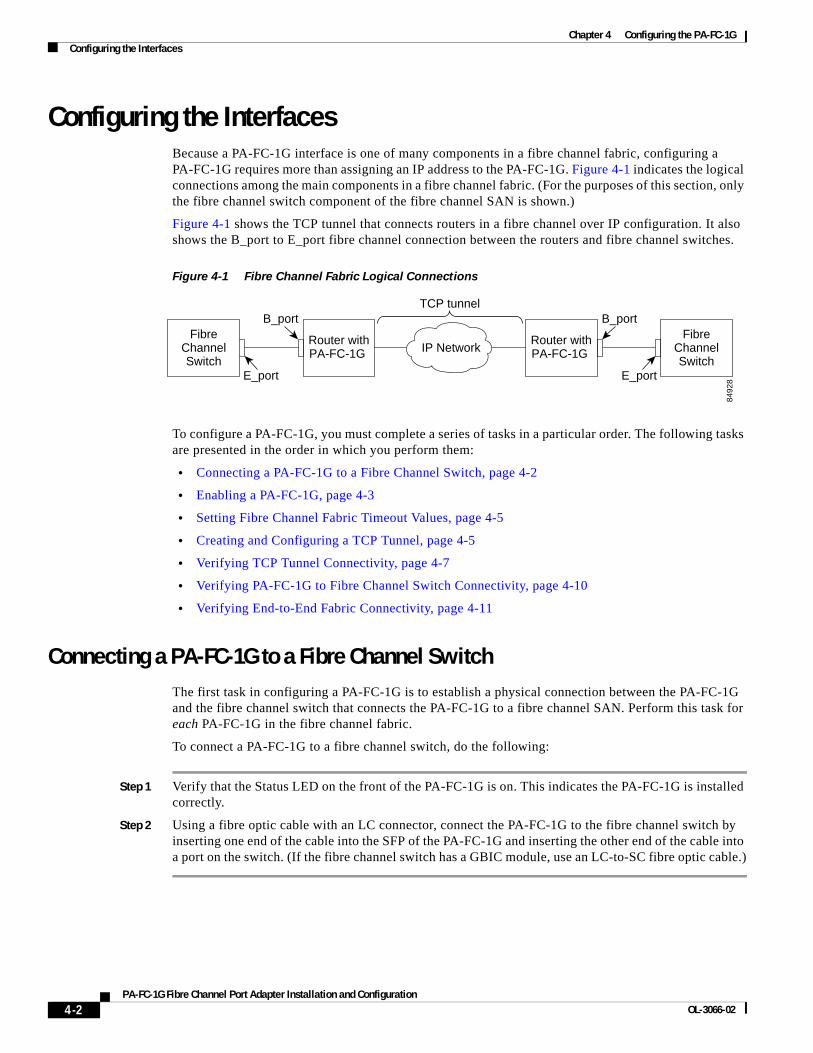
Configuring the Interfaces Because a PA-FC-1G interface is one of many components in a fibre channel fabric, configuring a PA-FC-1G requires more than assigning an IP address to the PA-FC-1G. Figure 4-1 indicates the logical connections among the main components in a fibre channel fabric. (For the purposes of this section, only the fibre channel switch component of the fibre channel SAN is shown.)
Figure 4-1 shows the TCP tunnel that connects routers in a fibre channel over IP configuration. It also shows the B_port to E_port fibre channel connection between the routers and fibre channel switches.
Figure 4-1 Fibre Channel Fabric Logical Connections
To configure a PA-FC-1G, you must complete a series of tasks in a particular order. The following tasks are presented in the order in which you perform them:
• Connecting a PA-FC-1G to a Fibre Channel Switch, page 4-2
• Enabling a PA-FC-1G, page 4-3
• Setting Fibre Channel Fabric Timeout Values, page 4-5
• Creating and Configuring a TCP Tunnel, page 4-5
• Verifying TCP Tunnel Connectivity, page 4-7
• Verifying PA-FC-1G to Fibre Channel Switch Connectivity, page 4-10
• Verifying End-to-End Fabric Connectivity, page 4-11
Connecting a PA-FC-1G to a Fibre Channel SwitchThe first task in configuring a PA-FC-1G is to establish a physical connection between the PA-FC-1G and the fibre channel switch that connects the PA-FC-1G to a fibre channel SAN. Perform this task for each PA-FC-1G in the fibre channel fabric.
To connect a PA-FC-1G to a fibre channel switch, do the following:
Step 1 Verify that the Status LED on the front of the PA-FC-1G is on. This indicates the PA-FC-1G is installed correctly.
Step 2 Using a fibre optic cable with an LC connector, connect the PA-FC-1G to the fibre channel switch by inserting one end of the cable into the SFP of the PA-FC-1G and inserting the other end of the cable into a port on the switch. (If the fibre channel switch has a GBIC module, use an LC-to-SC fibre optic cable.)
FibreChannelSwitch
E_port
FibreChannelSwitch
Router withPA-FC-1G
Router withPA-FC-1G IP Network
TCP tunnel
8492
8
B_port
E_port
B_port
4-2PA-FC-1G Fibre Channel Port Adapter Installation and Configuration
OL-3066-02

Chapter 4 Configuring the PA-FC-1GConfiguring the Interfaces
Enabling a PA-FC-1GAfter verifying a physical connection between a PA-FC-1G and a fibre channel switch, you must assign an IP address to the PA-FC-1G and then enable it. Perform this task for each PA-FC-1G in the fibre channel fabric.
To enable a PA-FC-1G, do the following:
Step 1 Enter the privileged level of the EXEC command interpreter (also called enable mode). (See the “Using the EXEC Command Interpreter” section on page 4-1 for instructions.)
Step 2 At the privileged-level prompt, enter configuration mode and specify that the console terminal is the source of the configuration commands.
Router# configure terminalEnter configuration commands, one per line. End with CNTL/Z.Router(config)#
Step 3 Specify the interface to be enabled using the interface command followed by the interface type and address. The address consists of the slot number of the router and the port number on the PA-FC-1G. (Because the PA-FC-1G has only one port, the port number is always 0.)
Router(config)# interface fcpa 2/0Router(config-if)#
Step 4 You are now in interface configuration mode. Assign an IP address and subnet mask to the PA-FC-1G using the ip address command.
Router(config-if)# ip address 10.1.1.1 255.255.255.0
Step 5 Enable the PA-FC-1G using the no shutdown command.
Router(config-if)# no shutdown
Step 6 Exit interface configuration mode and then configuration mode by pressing Ctrl-Z—hold down the Control key while you press Z—or entering end or exit to return to the EXEC command interpreter.
Router(config-if)# exitRouter(config)# exitRouter#
Step 7 Write the new configuration to NVRAM.
Router# copy running-config startup-config[OK]Router#
The system displays an OK message when the configuration has been stored in NVRAM.
Step 8 Verify that the PA-FC-1G and line protocol are up using the show interfaces command followed by the interface type and address.
Router# show interfaces fcpa 2/0Fcpa2/0 is up, line protocol is up Hardware is FC over TCP/IP
4-3PA-FC-1G Fibre Channel Port Adapter Installation and Configuration
OL-3066-02
Chapter 4 Configuring the PA-FC-1GConfiguring the Interfaces
Default Configuration Values
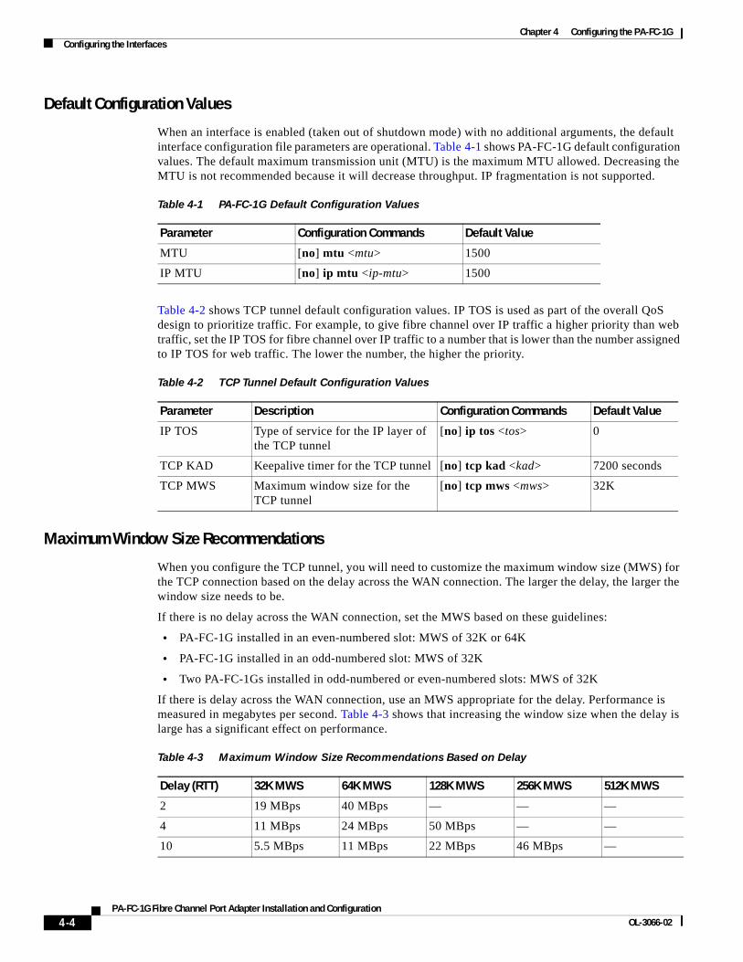
When an interface is enabled (taken out of shutdown mode) with no additional arguments, the default interface configuration file parameters are operational. Table 4-1 shows PA-FC-1G default configuration values. The default maximum transmission unit (MTU) is the maximum MTU allowed. Decreasing the MTU is not recommended because it will decrease throughput. IP fragmentation is not supported.
Table 4-2 shows TCP tunnel default configuration values. IP TOS is used as part of the overall QoS design to prioritize traffic. For example, to give fibre channel over IP traffic a higher priority than web traffic, set the IP TOS for fibre channel over IP traffic to a number that is lower than the number assigned to IP TOS for web traffic. The lower the number, the higher the priority.
Maximum Window Size Recommendations
When you configure the TCP tunnel, you will need to customize the maximum window size (MWS) for the TCP connection based on the delay across the WAN connection. The larger the delay, the larger the window size needs to be.
If there is no delay across the WAN connection, set the MWS based on these guidelines:
• PA-FC-1G installed in an even-numbered slot: MWS of 32K or 64K
• PA-FC-1G installed in an odd-numbered slot: MWS of 32K
• Two PA-FC-1Gs installed in odd-numbered or even-numbered slots: MWS of 32K
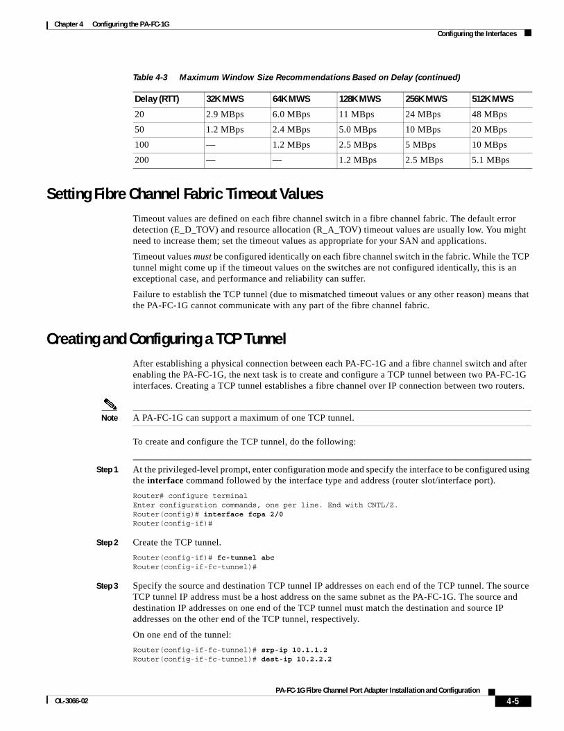
If there is delay across the WAN connection, use an MWS appropriate for the delay. Performance is measured in megabytes per second. Table 4-3 shows that increasing the window size when the delay is large has a significant effect on performance.
Table 4-1 PA-FC-1G Default Configuration Values
Parameter Configuration Commands Default Value
MTU [no] mtu <mtu> 1500
IP MTU [no] ip mtu <ip-mtu> 1500
Table 4-2 TCP Tunnel Default Configuration Values
Parameter Description Configuration Commands Default Value
IP TOS Type of service for the IP layer of the TCP tunnel
[no] ip tos <tos> 0
TCP KAD Keepalive timer for the TCP tunnel [no] tcp kad <kad> 7200 seconds
TCP MWS Maximum window size for the TCP tunnel
[no] tcp mws <mws> 32K
Table 4-3 Maximum Window Size Recommendations Based on Delay
Delay (RTT) 32K MWS 64K MWS 128K MWS 256K MWS 512K MWS
2 19 MBps 40 MBps — — —
4 11 MBps 24 MBps 50 MBps — —
10 5.5 MBps 11 MBps 22 MBps 46 MBps —
4-4PA-FC-1G Fibre Channel Port Adapter Installation and Configuration
OL-3066-02
Chapter 4 Configuring the PA-FC-1GConfiguring the Interfaces
Setting Fibre Channel Fabric Timeout ValuesTimeout values are defined on each fibre channel switch in a fibre channel fabric. The default error detection (E_D_TOV) and resource allocation (R_A_TOV) timeout values are usually low. You might need to increase them; set the timeout values as appropriate for your SAN and applications.
Timeout values must be configured identically on each fibre channel switch in the fabric. While the TCP tunnel might come up if the timeout values on the switches are not configured identically, this is an exceptional case, and performance and reliability can suffer.
Failure to establish the TCP tunnel (due to mismatched timeout values or any other reason) means that the PA-FC-1G cannot communicate with any part of the fibre channel fabric.
Creating and Configuring a TCP TunnelAfter establishing a physical connection between each PA-FC-1G and a fibre channel switch and after enabling the PA-FC-1G, the next task is to create and configure a TCP tunnel between two PA-FC-1G interfaces. Creating a TCP tunnel establishes a fibre channel over IP connection between two routers.
Note A PA-FC-1G can support a maximum of one TCP tunnel.
To create and configure the TCP tunnel, do the following:
Step 1 At the privileged-level prompt, enter configuration mode and specify the interface to be configured using the interface command followed by the interface type and address (router slot/interface port).
Router# configure terminalEnter configuration commands, one per line. End with CNTL/Z.Router(config)# interface fcpa 2/0Router(config-if)#
Step 2 Create the TCP tunnel.
Router(config-if)# fc-tunnel abcRouter(config-if-fc-tunnel)#
Step 3 Specify the source and destination TCP tunnel IP addresses on each end of the TCP tunnel. The source TCP tunnel IP address must be a host address on the same subnet as the PA-FC-1G. The source and destination IP addresses on one end of the TCP tunnel must match the destination and source IP addresses on the other end of the TCP tunnel, respectively.
On one end of the tunnel:
Router(config-if-fc-tunnel)# srp-ip 10.1.1.2Router(config-if-fc-tunnel)# dest-ip 10.2.2.2
20 2.9 MBps 6.0 MBps 11 MBps 24 MBps 48 MBps
50 1.2 MBps 2.4 MBps 5.0 MBps 10 MBps 20 MBps
100 — 1.2 MBps 2.5 MBps 5 MBps 10 MBps
200 — — 1.2 MBps 2.5 MBps 5.1 MBps
Table 4-3 Maximum Window Size Recommendations Based on Delay (continued)
Delay (RTT) 32K MWS 64K MWS 128K MWS 256K MWS 512K MWS
4-5PA-FC-1G Fibre Channel Port Adapter Installation and Configuration
OL-3066-02

Chapter 4 Configuring the PA-FC-1GConfiguring the Interfaces
On the other end of the tunnel:
Router(config-if-fc-tunnel)# srp-ip 10.2.2.2Router(config-if-fc-tunnel)# dest-ip 10.1.1.2
Step 4 Specify the source and destination TCP tunnel ports on each end of the tunnel. The source and destination ports on one end of the TCP tunnel must match the destination and source ports on the other end of the TCP tunnel, respectively.
On one end of the tunnel:
Router(config-if-fc-tunnel)# src-port 2000Router(config-if-fc-tunnel)# dest-port 3000
On the other end of the tunnel:
Router(config-if-fc-tunnel)# src-port 3000Router(config-if-fc-tunnel)# dest-port 2000
Step 5 Customize the maximum window size for the TCP tunnel based on the delay across the WAN connection using the tcp mws command. Do this on both ends of the TCP tunnel. See the “Maximum Window Size Recommendations” section on page 4-4.
Step 6 If required for your TCP tunnel, change the type of service, or keepalive timer using the ip tos and tcp kad commands, respectively. Do this on both ends of the TCP tunnel.
Step 7 Activate the TCP tunnel using the inservice command.
Router(config-if-fc-tunnel)# inservice
Step 8 Exit tunnel configuration mode, interface configuration mode, and configuration mode by pressing Ctrl-Z—hold down the Control key while you press Z—or entering end or exit to return to the EXEC command interpreter.
Router(config-if-fc-tunnel)# exitRouter(config-if)# exitRouter(config)# exitRouter#
Step 9 Write the new configuration to NVRAM as follows:
Router# copy running-config startup-config[OK]Router#
Changing the TCP Tunnel Configuration
If you need to tune or modify the TCP tunnel configuration after the TCP tunnel is established, you must first take the TCP tunnel out of service using the no inservice command. The following example shows how to change the IP TOS value from 0 to 1 for an established tunnel.
Router(config-if)# fc-tunnel abcRouter(config-if-fc-tunnel)# no inserviceRouter(config-if-fc-tunnel)# ip tos 1Router(config-if-fc-tunnel)# inservice
4-6PA-FC-1G Fibre Channel Port Adapter Installation and Configuration
OL-3066-02
Chapter 4 Configuring the PA-FC-1GConfiguring the Interfaces
Configuring for Multiple SANs
Two fibre channel SANs can be connected by establishing a TCP tunnel between two PA-FC-1G interfaces, each residing in a separate router. Additional PA-FC-1G interfaces can be installed in each router and multiple TCP tunnels can be configured, thus allowing multiple fibre channel SANs to be interconnected.
However, additional TCP tunnels must be defined using different PA-FC-1G port adapters, different IP addresses on different subnets, different source and destination TCP tunnel IP addresses, and different source and destination TCP tunnel ports.
Verifying TCP Tunnel ConnectivityVerifying TCP tunnel connectivity requires checking that the TCP tunnel is correctly configured and verifying that the TCP tunnel is working properly. To verify TCP tunnel connectivity, proceed with the following tasks:
• Checking TCP Tunnel Configuration, page 4-7
• Checking the TCP Tunnel Is Working Properly, page 4-9
Checking TCP Tunnel Configuration
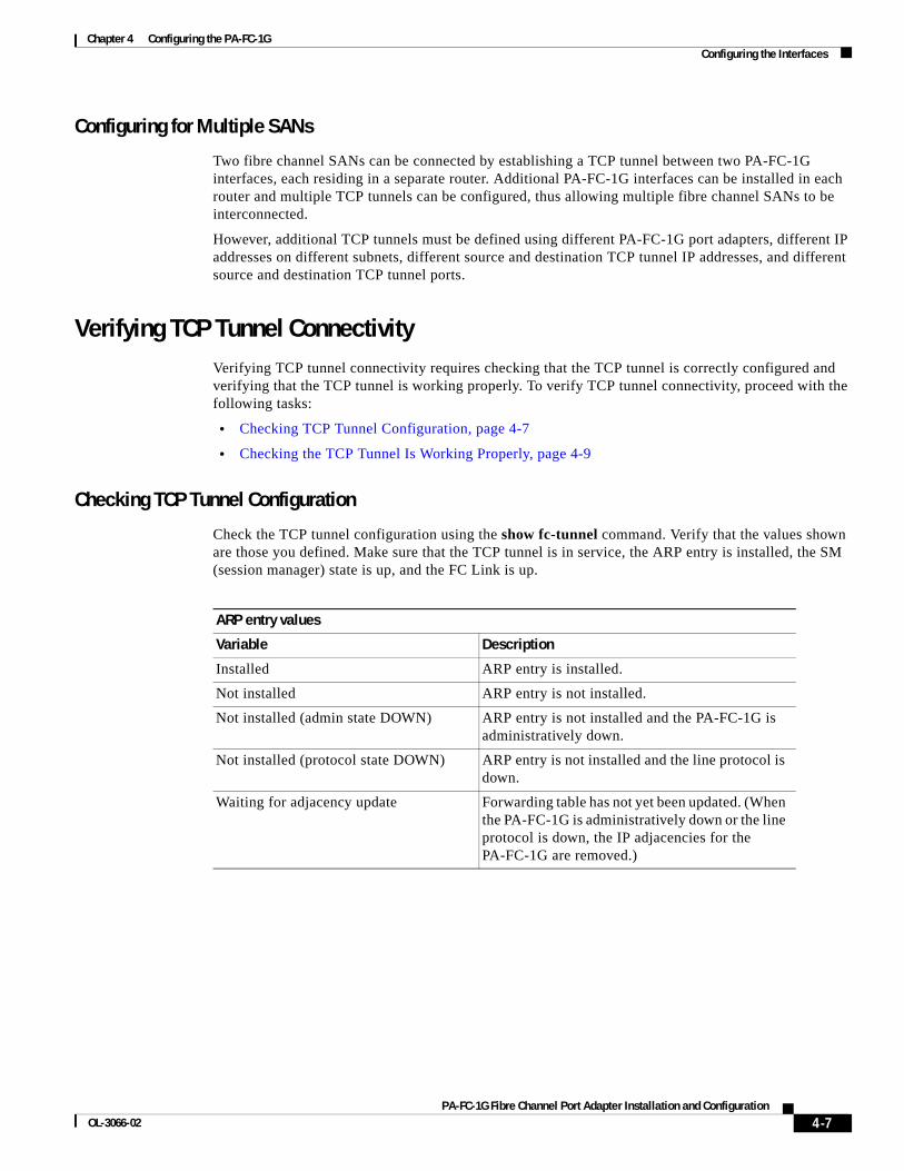
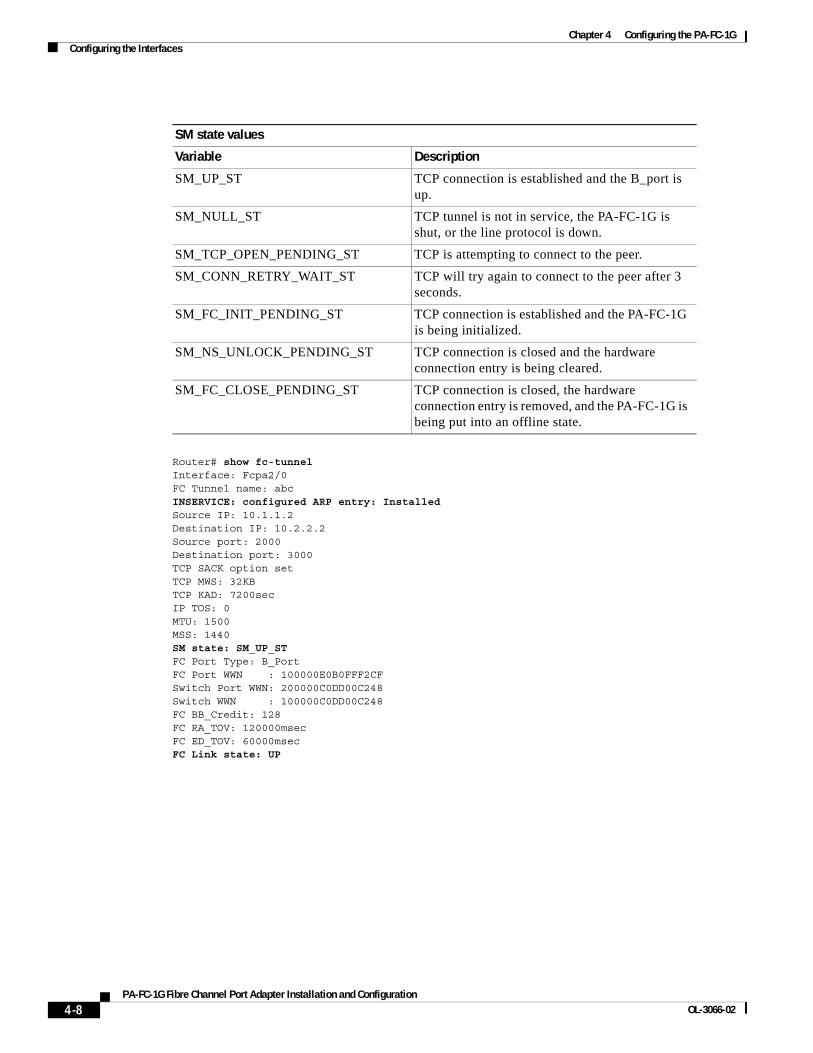
Check the TCP tunnel configuration using the show fc-tunnel command. Verify that the values shown are those you defined. Make sure that the TCP tunnel is in service, the ARP entry is installed, the SM (session manager) state is up, and the FC Link is up.
ARP entry values
Variable Description
Installed ARP entry is installed.
Not installed ARP entry is not installed.
Not installed (admin state DOWN) ARP entry is not installed and the PA-FC-1G is administratively down.
Not installed (protocol state DOWN) ARP entry is not installed and the line protocol is down.
Waiting for adjacency update Forwarding table has not yet been updated. (When the PA-FC-1G is administratively down or the line protocol is down, the IP adjacencies for the PA-FC-1G are removed.)
4-7PA-FC-1G Fibre Channel Port Adapter Installation and Configuration
OL-3066-02
Chapter 4 Configuring the PA-FC-1GConfiguring the Interfaces
Router# show fc-tunnel Interface: Fcpa2/0 FC Tunnel name: abcINSERVICE: configured ARP entry: InstalledSource IP: 10.1.1.2 Destination IP: 10.2.2.2 Source port: 2000 Destination port: 3000 TCP SACK option set TCP MWS: 32KB TCP KAD: 7200sec IP TOS: 0 MTU: 1500MSS: 1440SM state: SM_UP_STFC Port Type: B_PortFC Port WWN : 100000E0B0FFF2CFSwitch Port WWN: 200000C0DD00C248Switch WWN : 100000C0DD00C248FC BB_Credit: 128FC RA_TOV: 120000msecFC ED_TOV: 60000msecFC Link state: UP
SM state values
Variable Description
SM_UP_ST TCP connection is established and the B_port is up.
SM_NULL_ST TCP tunnel is not in service, the PA-FC-1G is shut, or the line protocol is down.
SM_TCP_OPEN_PENDING_ST TCP is attempting to connect to the peer.
SM_CONN_RETRY_WAIT_ST TCP will try again to connect to the peer after 3 seconds.
SM_FC_INIT_PENDING_ST TCP connection is established and the PA-FC-1G is being initialized.
SM_NS_UNLOCK_PENDING_ST TCP connection is closed and the hardware connection entry is being cleared.
SM_FC_CLOSE_PENDING_ST TCP connection is closed, the hardware connection entry is removed, and the PA-FC-1G is being put into an offline state.
4-8PA-FC-1G Fibre Channel Port Adapter Installation and Configuration
OL-3066-02
Chapter 4 Configuring the PA-FC-1GConfiguring the Interfaces
Checking the TCP Tunnel Is Working Properly
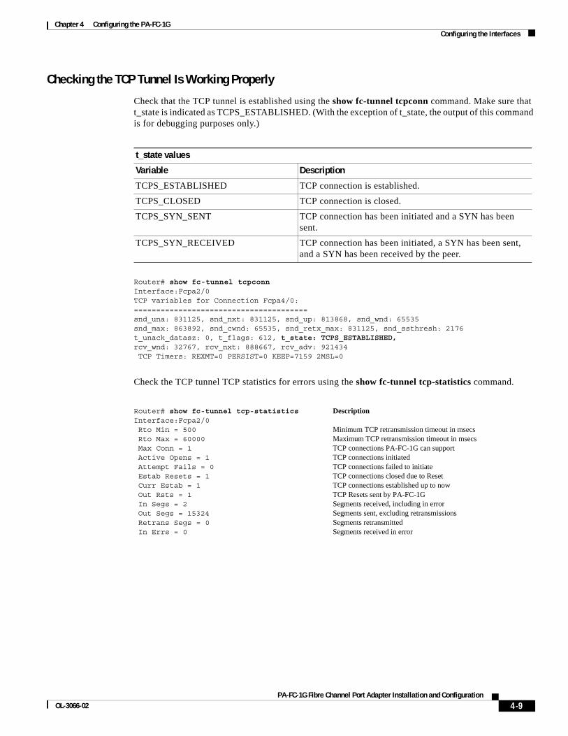
Check that the TCP tunnel is established using the show fc-tunnel tcpconn command. Make sure that t_state is indicated as TCPS_ESTABLISHED. (With the exception of t_state, the output of this command is for debugging purposes only.)
Router# show fc-tunnel tcpconn Interface:Fcpa2/0TCP variables for Connection Fcpa4/0:=======================================snd_una: 831125, snd_nxt: 831125, snd_up: 813868, snd_wnd: 65535snd_max: 863892, snd_cwnd: 65535, snd_retx_max: 831125, snd_ssthresh: 2176t_unack_datasz: 0, t_flags: 612, t_state: TCPS_ESTABLISHED,rcv_wnd: 32767, rcv_nxt: 888667, rcv_adv: 921434 TCP Timers: REXMT=0 PERSIST=0 KEEP=7159 2MSL=0
Check the TCP tunnel TCP statistics for errors using the show fc-tunnel tcp-statistics command.
t_state values
Variable Description
TCPS_ESTABLISHED TCP connection is established.
TCPS_CLOSED TCP connection is closed.
TCPS_SYN_SENT TCP connection has been initiated and a SYN has been sent.
TCPS_SYN_RECEIVED TCP connection has been initiated, a SYN has been sent, and a SYN has been received by the peer.
Router# show fc-tunnel tcp-statistics Interface:Fcpa2/0 Rto Min = 500 Rto Max = 60000 Max Conn = 1 Active Opens = 1 Attempt Fails = 0 Estab Resets = 1 Curr Estab = 1 Out Rsts = 1 In Segs = 2 Out Segs = 15324 Retrans Segs = 0 In Errs = 0
Description
Minimum TCP retransmission timeout in msecsMaximum TCP retransmission timeout in msecsTCP connections PA-FC-1G can supportTCP connections initiatedTCP connections failed to initiateTCP connections closed due to ResetTCP connections established up to nowTCP Resets sent by PA-FC-1GSegments received, including in errorSegments sent, excluding retransmissionsSegments retransmittedSegments received in error
4-9PA-FC-1G Fibre Channel Port Adapter Installation and Configuration
OL-3066-02

Chapter 4 Configuring the PA-FC-1GConfiguring the Interfaces
Check the TCP tunnel fibre channel statistics for errors using the show fc-tunnel fc-statistics command.
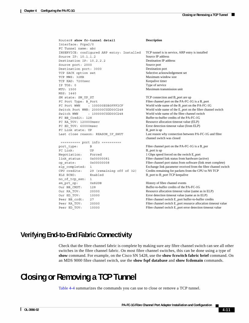
Verifying PA-FC-1G to Fibre Channel Switch ConnectivityCheck the connectivity between each PA-FC-1G and the fibre channel switch by using the show fc-tunnel detail command. Make sure that elp_completed is indicated as 1. This means that an exchange link parameter has been received by the router from the fibre channel switch and that the B_port on the router has been successfully initialized.
Note that in addition to the information shown in the show fc-tunnel command output, the show fc-tunnel detail command output indicates a reason why the connection between the PA-FC-1G and the fibre channel switch was closed (Last close reason) and port information.
Router# show fc-tunnel fc-statistics Interface:Fcpa2/0Link failure events = 0Sync loss events = 1Signal loss events = 0Pseq error events = 0Rx inv words = 2rx crc error frames = 0Delim error frames = 0Rx class2 frames = 0Rx class2 octets = 0Rx class3 frames = 0Rx class3 octets = 0Rx class2 frames = 0Rx class2 octets = 0Rx class3 frames = 0Rx class3 octets =
Description
Port link failuresWord Sync loss occurrencesSignal loss occurrencesPrimitive error sequence occurrencesInvalid transmission wordsFibre channel frames received with CRC errorsFibre channel frames received with invalid EOF/lengthFibre channel class 2 frames receivedFibre channel class 2 bytes receivedFibre channel class 3 frames receivedFibre channel class 3 bytes receivedFibre channel class 2 frames sentFibre channel class 2 bytes sentFibre channel class 3 frames sentFibre channel class 3 bytes sent
Last close reason values
Variable Description
REASON_CLI_CLOSED no inservice command was issued by the user.
REASON_CLI_RESET no fc-tunnel command was issued by the user.
REASON_PEER_CLOSED Connection was closed by the peer.
REASON_TCP_CLOSED Connection was closed by TCP because an error was detected.
REASON_ICMP_UNFRAG_CLOSED Connection was closed because an ICMP unreachable packet was received with UNFRAG code.
REASON_NS_TCP_RESET Connection was closed by hardware TCP because of multiple retransmissions.
REASON_FC_ERROR Connection was closed because of a fibre channel protocol error.
REASON_IF_SHUT Connection was closed because the PA-FC-1G was shut.
REASON_LINE_PROTOCOL_DOWN Connection was closed because the line protocol is down.
REASON_CLEAR_INTERFACE_ISSUED clear interface command issued by the user.
REASON_CARD_REMOVED PA-FC-1G was removed from the router.
4-10PA-FC-1G Fibre Channel Port Adapter Installation and Configuration
OL-3066-02
Chapter 4 Configuring the PA-FC-1GClosing or Removing a TCP Tunnel
Verifying End-to-End Fabric ConnectivityCheck that the fibre channel fabric is complete by making sure any fibre channel switch can see all other switches in the fibre channel fabric. On most fibre channel switches, this can be done using a type of show command. For example, on the Cisco SN 5428, use the show fcswitch fabric brief command. On an MDS 9000 fibre channel switch, use the show fspf database and show fcdomain commands.
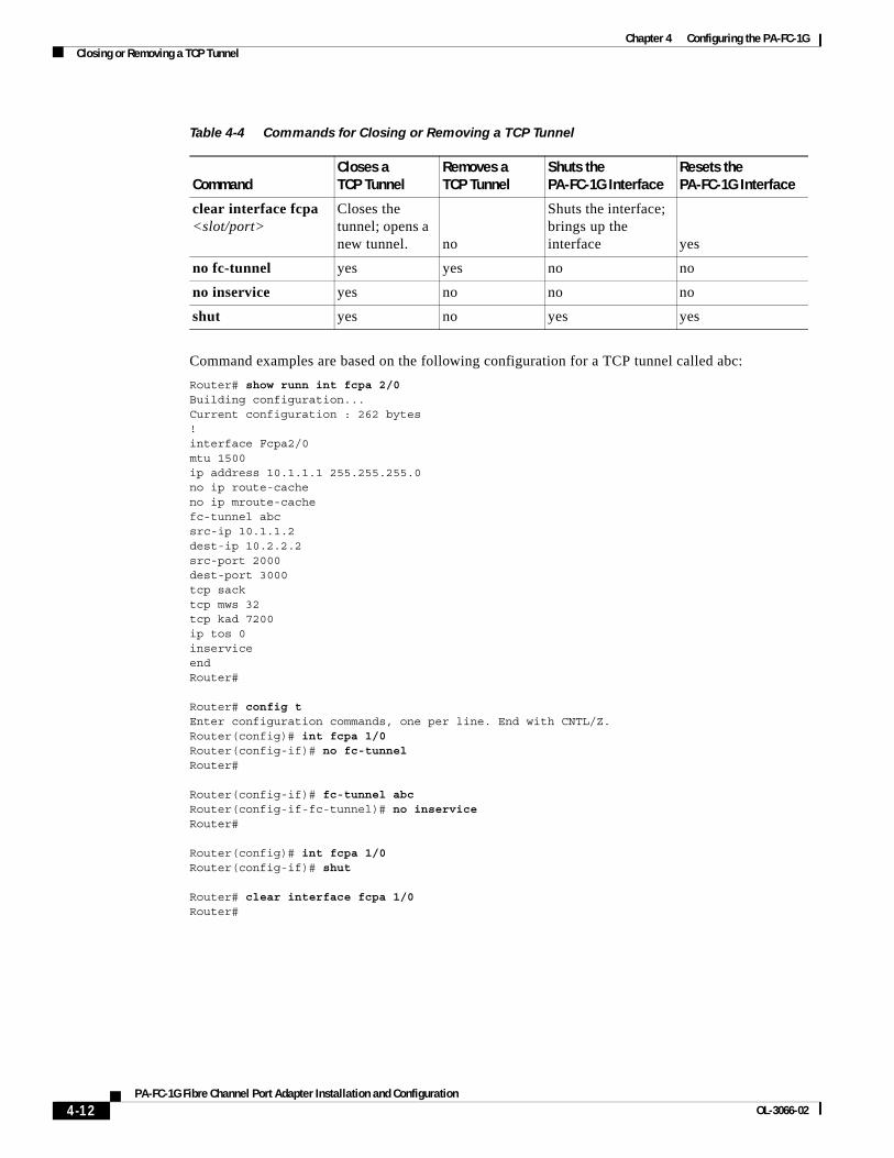
Closing or Removing a TCP TunnelTable 4-4 summarizes the commands you can use to close or remove a TCP tunnel.
Router# show fc-tunnel detailInterface: Fcpa2/0 FC Tunnel name: abcINSERVICE: configured ARP entry: InstalledSource IP: 10.1.1.2 Destination IP: 10.2.2.2 Source port: 2000 Destination port: 3000 TCP SACK option set TCP MWS: 32KB TCP KAD: 7200sec IP TOS: 0 MTU: 1500MSS: 1440SM state: SM_UP_STFC Port Type: B_PortFC Port WWN : 100000E0B0FFF2CFSwitch Port WWN: 200000C0DD00C248Switch WWN : 100000C0DD00C248FC BB_Credit: 128FC RA_TOV: 120000msecFC ED_TOV: 60000msecFC Link state: UPLast close reason: REASON_IF_SHUT
========== port info ==========port_type: BFC Link: UPNegotiation: Forcedlink_status: 0x00000081op_state: 0x00000008elp_completed: 1CPU credits: 29 (remaining off of 32)ELS ECHO: Enabledno_of_tcp_ssn: 1sm_prt_op: 0x82DBOur BB_CRDT: 128Our RA_TOV: 20000Our ED_TOV: 10000Peer BB_crdt: 27 Peer RA_TOV: 20000Peer ED_TOV: 10000
Description
TCP tunnel is in service, ARP entry is installedSource IP addressDestination IP addressSource portDestination portSelective acknowledgement setMaximum window sizeKeepalive timerType of serviceMaximum transmission unit
TCP connection and B_port are upFibre channel port on the PA-FC-1G is a B_portWorld wide name of the B_port on the PA-FC-1GWorld wide name of the E_port on the fibre channel switchWorld wide name of the fibre channel switchBuffer-to-buffer credits of the PA-FC-1GResource allocation timeout value (ELP)Error detection timeout value (from ELP)B_port is upLast reason why connection between PA-FC-1G and fibre channel switch was closed
Fibre channel port on the PA-FC-1G is a B_porB_port is up1 Gbps speed forced on the switch E_portFibre channel link status from hardware (active)Fibre channel port status from software (link reset complete)Exchange link parameter received from the fibre channel switchCredits remaining for packets from the CPU to NS TCPB_port to B_port TCP keepalive
History of fibre channel eventsBuffer-to-buffer credits of the PA-FC-1GResource allocation timeout value (same as in ELP)Error detection timeout value (same as in ELP)Fibre channel switch E_port buffer-to-buffer creditsFibre channel switch E_port resource allocation timeout valueFibre channel switch E_port error detection timeout value
4-11PA-FC-1G Fibre Channel Port Adapter Installation and Configuration
OL-3066-02
Chapter 4 Configuring the PA-FC-1GClosing or Removing a TCP Tunnel
Command examples are based on the following configuration for a TCP tunnel called abc:
Router# show runn int fcpa 2/0Building configuration... Current configuration : 262 bytes!interface Fcpa2/0mtu 1500ip address 10.1.1.1 255.255.255.0no ip route-cacheno ip mroute-cachefc-tunnel abcsrc-ip 10.1.1.2dest-ip 10.2.2.2src-port 2000dest-port 3000tcp sacktcp mws 32tcp kad 7200ip tos 0inserviceendRouter#
Router# config tEnter configuration commands, one per line. End with CNTL/Z.Router(config)# int fcpa 1/0Router(config-if)# no fc-tunnelRouter#
Router(config-if)# fc-tunnel abcRouter(config-if-fc-tunnel)# no inserviceRouter#
Router(config)# int fcpa 1/0Router(config-if)# shut
Router# clear interface fcpa 1/0Router#
Table 4-4 Commands for Closing or Removing a TCP Tunnel
CommandCloses a TCP Tunnel
Removes a TCP Tunnel
Shuts the PA-FC-1G Interface
Resets the PA-FC-1G Interface
clear interface fcpa <slot/port>
Closes the tunnel; opens a new tunnel. no
Shuts the interface; brings up the interface yes
no fc-tunnel yes yes no no
no inservice yes no no no
shut yes no yes yes
4-12PA-FC-1G Fibre Channel Port Adapter Installation and Configuration
OL-3066-02
Chapter 4 Configuring the PA-FC-1GChecking the Configuration
Checking the Configuration After configuring the new interface, use show commands to display the status of the new interface or all interfaces, and use the ping command to check connectivity. This section includes the following subsections:
• Using show Commands to Verify the New Interface Status, page 4-13
• Using the ping Command to Verify Network Connectivity, page 4-20
Using show Commands to Verify the New Interface Status This section demonstrates how you can use the show commands to verify that new interfaces are configured and operating correctly and that the port adapter appears in them correctly. Sample displays of the output of selected show commands appear in the sections that follow. For complete command descriptions and examples, refer to the publications listed in the “Related Documentation” section on page viii.
If an interface is shut down and you configured it as up, or if the displays indicate that the hardware is not functioning properly, ensure that the interface is properly connected and terminated. If you still have problems bringing up the interface, contact a service representative for assistance. This section includes the following subsections:
• Using the show controllers Commands, page 4-13
• Using the show protocols Command, page 4-15
• Using the show running-config Command, page 4-15
• Using the show startup-config Command, page 4-16
• Using the show version or show hardware Commands, page 4-18
• Using the show diag Command, page 4-19
• Using the show interfaces Command, page 4-19
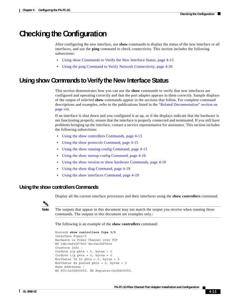
Using the show controllers Commands
Display all the current interface processors and their interfaces using the show controllers command.
Note The outputs that appear in this document may not match the output you receive when running these commands. The outputs in this document are examples only.:
The following is an example of the show controllers command:
Router# show controllers fcpa 3/0 Interface Fcpa3/0 Hardware is Fiber Channel over TCP NS idb=0x62DF785C ds=0x62DF9904 Counters Info : Cordova o/p pkts = 0, bytes = 0 Cordova i/p pkts = 0, bytes = 0 Northstar Tx fc pkts = 0, bytes = 0 Northstar Rx punted pkts = 0, bytes = 0 Base Addresses : NS PCI=0x3D800000, NS Register=0x3D800C00,
4-13PA-FC-1G Fibre Channel Port Adapter Installation and Configuration
OL-3066-02
Chapter 4 Configuring the PA-FC-1GChecking the Configuration
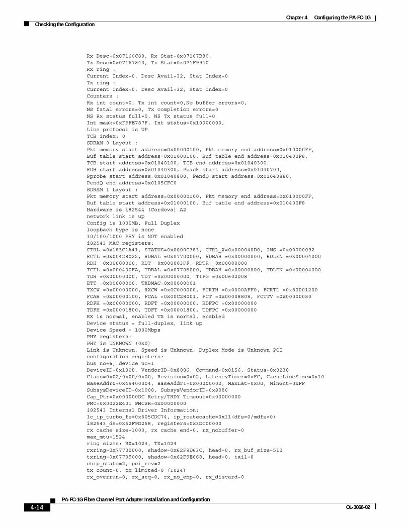
Rx Desc=0x07166C80, Rx Stat=0x07167B80, Tx Desc=0x07167840, Tx Stat=0x071F9940 Rx ring : Current Index=0, Desc Avail=32, Stat Index=0 Tx ring : Current Index=0, Desc Avail=32, Stat Index=0 Counters : Rx int count=0, Tx int count=0,No buffer errors=0, NS fatal errors=0, Tx completion errors=0 NS Rx status full=0, NS Tx status full=0 Int mask=0xFFFE787F, Int status=0x10000000, Line protocol is UP TCB index: 0 SDRAM 0 Layout : Pkt memory start address=0x00000100, Pkt memory end address=0x010000FF, Buf table start address=0x01000100, Buf table end address=0x010400F8, TCB start address=0x01040100, TCB end address=0x01040300, ROB start address=0x01040300, Pback start address=0x01040700, Pprobe start address=0x01040800, PendQ start address=0x01040880, PendQ end address=0x0105CFC0 SDRAM 1 Layout : Pkt memory start address=0x00000100, Pkt memory end address=0x010000FF, Buf table start address=0x01000100, Buf table end address=0x010400F8 Hardware is i82544 (Cordova) A2 network link is up Config is 1000MB, Full Duplex loopback type is none 10/100/1000 PHY is NOT enabled i82543 MAC registers: CTRL =0x183C1A41, STATUS=0x0000C383, CTRL_X=0x000040D0, IMS =0x00000092 RCTL =0x00428022, RDBAL =0x07700000, RDBAH =0x00000000, RDLEN =0x00004000 RDH =0x00000000, RDT =0x000003FF, RDTR =0x00000000 TCTL =0x000400FA, TDBAL =0x07705000, TDBAH =0x00000000, TDLEN =0x00004000 TDH =0x00000000, TDT =0x00000000, TIPG =0x00602008 ETT =0x00000000, TXDMAC=0x00000001 TXCW =0x00000000, RXCW =0x0C000000, FCRTH =0x0000AFF0, FCRTL =0x80001200 FCAH =0x00000100, FCAL =0x00C28001, FCT =0x00008808, FCTTV =0x00000080 RDFH =0x00000000, RDFT =0x00000000, RDFPC =0x00000000 TDFH =0x00001800, TDFT =0x00001800, TDFPC =0x00000000 RX is normal, enabled TX is normal, enabled Device status = full-duplex, link up Device Speed = 1000Mbps PHY registers: PHY is UNKNOWN (0x0) Link is Unknown, Speed is Unknown, Duplex Mode is Unknown PCI configuration registers: bus_no=6, device_no=1 DeviceID=0x1008, VendorID=0x8086, Command=0x0156, Status=0x0230 Class=0x02/0x00/0x00, Revision=0x02, LatencyTimer=0xFC, CacheLineSize=0x10 BaseAddr0=0x49400004, BaseAddr1=0x00000000, MaxLat=0x00, MinGnt=0xFF SubsysDeviceID=0x1008, SubsysVendorID=0x8086 Cap_Ptr=0x000000DC Retry/TRDY Timeout=0x00000000 PMC=0x0022E401 PMCSR=0x00000000 i82543 Internal Driver Information: lc_ip_turbo_fs=0x605CDC74, ip_routecache=0x11(dfs=0/mdfs=0) i82543_ds=0x62F9D268, registers=0x3DC00000 rx cache size=1000, rx cache end=0, rx_nobuffer=0 max_mtu=1524 ring sizes: RX=1024, TX=1024 rxring=0x77700000, shadow=0x62F9D63C, head=0, rx_buf_size=512 txring=0x07705000, shadow=0x62F9E668, head=0, tail=0 chip_state=2, pci_rev=2 tx_count=0, tx_limited=0 (1024) rx_overrun=0, rx_seq=0, rx_no_enp=0, rx_discard=0
4-14PA-FC-1G Fibre Channel Port Adapter Installation and Configuration
OL-3066-02

Chapter 4 Configuring the PA-FC-1GChecking the Configuration
throttled=0, enabled=0, disabled=0, bypassed=0 reset=2(init=1, check=0, restart=1, pci=0), auto_restart=2 link_reset=0, tx_carrier_loss=0, fatal_tx_err=0 isl_err=0, wait_for_last_tdt=0, rx_stuck=0 tx_stuck=0, rx_max_spin=1 HW addr filter: 0x62DF9E80, ISL disabled, Promiscuous mode disabled Entry= 0: Addr=000A.8B63.2C06 (All other entries are empty) i82543 Statistics CRC error 0 Symbol error 0 Missed Packets 0 Single Collision 0 Excessive Coll 0 Multiple Coll 0 Late Coll 0 Collision 0 Defer 0 Receive Length 0 Sequence Error 0 XON RX 0 XON TX 0 XOFF RX 0 XOFF TX 0 FC RX Unsupport 0 Packet RX (64) 0 Packet RX (127) 0 Packet RX (255) 0 Packet RX (511) 0 Packet RX (1023) 0 Packet RX (1522) 0 Good Packet RX 0 Broadcast RX 0 Multicast RX 0 Good Packet TX 0 Good Octets RX.H 0 Good Octets RX.L 0 Good Octets TX.H 0 Good Octets TX.L 0 RX No Buff 0 RX Undersize 0 RX Fragment 0 RX Oversize 0 RX Octets High 0 RX Octets Low 0 TX Octets High 0 TX Octets Low 0 TX Packet 0 RX Packet 0 TX Broadcast 0 TX Multicast 0 Packet TX (64) 0 Packet TX (127) 0 Packet TX (255) 0 Packet TX (511) 0 Packet TX (1023) 0 Packet TX (1522) 0 TX Underruns 0 TX No CSR 0 RX Error Count 0 RX DMA Underruns 0 RX Carrier Ext 0 TCP Segmentation 0 TCP Seg Failed 0 Router#
Using the show protocols Command
Display protocols configured for the entire system and for specific interfaces using the show protocols command.
Note The outputs that appear in this document may not match the output you receive when running these commands. The outputs in this document are examples only.
The following is an example of the show protocols command:
Router# show protocols fcpa 6/0Fcpa6/0 is up, line protocol is upInternet address is 10.1.1.1/24Router#
Using the show running-config Command
Display the running configuration file using the show running-config command.
4-15PA-FC-1G Fibre Channel Port Adapter Installation and Configuration
OL-3066-02
Chapter 4 Configuring the PA-FC-1GChecking the Configuration
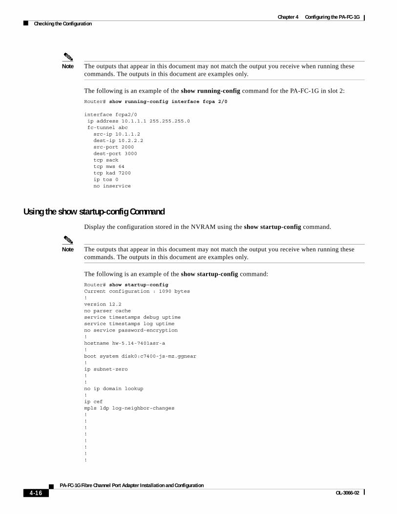
Note The outputs that appear in this document may not match the output you receive when running these commands. The outputs in this document are examples only.
The following is an example of the show running-config command for the PA-FC-1G in slot 2:
Router# show running-config interface fcpa 2/0
interface fcpa2/0 ip address 10.1.1.1 255.255.255.0 fc-tunnel abc src-ip 10.1.1.2 dest-ip 10.2.2.2 src-port 2000 dest-port 3000 tcp sack tcp mws 64 tcp kad 7200 ip tos 0 no inservice
Using the show startup-config Command
Display the configuration stored in the NVRAM using the show startup-config command.
Note The outputs that appear in this document may not match the output you receive when running these commands. The outputs in this document are examples only.
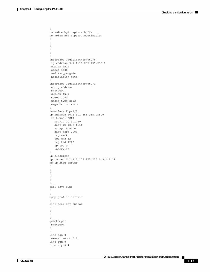
The following is an example of the show startup-config command:
Router# show startup-configCurrent configuration : 1090 bytes!version 12.2no parser cacheservice timestamps debug uptimeservice timestamps log uptimeno service password-encryption!hostname hw-5.14-7401asr-a!boot system disk0:c7400-js-mz.ggnear!ip subnet-zero!!no ip domain lookup!ip cefmpls ldp log-neighbor-changes!!!!!!!!
4-16PA-FC-1G Fibre Channel Port Adapter Installation and Configuration
OL-3066-02
Chapter 4 Configuring the PA-FC-1GChecking the Configuration
!no voice hpi capture bufferno voice hpi capture destination !!!!!!interface GigabitEthernet0/0 ip address 9.1.1.10 255.255.255.0 duplex full speed 1000 media-type gbic negotiation auto!interface GigabitEthernet0/1 no ip address shutdown duplex full speed 1000 media-type gbic negotiation auto!interface Fcpa1/0ip address 10.1.1.1 255.255.255.0 fc-tunnel GGPA src-ip 10.1.1.10 dest-ip 10.2.1.11 src-port 5200 dest-port 2000 tcp sack tcp mws 32 tcp kad 7200 ip tos 0 inservice!ip classlessip route 10.2.1.0 255.255.255.0 9.1.1.11no ip http server!!!!!!call rsvp-sync!!mgcp profile default!dial-peer cor custom!!!!gatekeeper shutdown!!line con 0 exec-timeout 0 0line aux 0line vty 0 4
4-17PA-FC-1G Fibre Channel Port Adapter Installation and Configuration
OL-3066-02

Chapter 4 Configuring the PA-FC-1GChecking the Configuration
loginline vty 5 15 login!!end
Using the show version or show hardware Commands
Display the configuration of the system hardware, the number of each interface type installed, the Cisco IOS software version, the names and sources of configuration files, and the boot images using the show version (or show hardware) command.
Note The outputs that appear in this document may not match the output you receive when running these commands. The outputs in this document are examples only.
Following is an example of the show version command from a Cisco 7401ASR router:
Router# show versionCisco Internetwork Operating System Software IOS (tm) 7400 Software (C7400-JS-M), Experimental Version 12.2(20021230:084514) [BLD-ggnear.ios-nightly 103]Copyright (c) 1986-2002 by cisco Systems, Inc.Compiled Mon 30-Dec-02 03:31 by irvrelImage text-base: 0x60008954, data-base: 0x61ED4000
ROM: System Bootstrap, Version 12.2(1r)DD1, RELEASE SOFTWARE (fc1)BOOTLDR: 7400 Software (C7400-KBOOT-M), Version 12.2(4)B4, EARLY DEPLOYMENT RELEASE SOFTWARE (fc1)
hw-5.14-7401asr-a uptime is 4 hours, 50 minutesSystem returned to ROM by power-onSystem image file is "disk0:c7400-js-mz.ggnear"
cisco 7401ASR (NSE) processor (revision A) with 491520K/32768K bytes of memory.Processor board ID 0R7000 CPU at 375Mhz, Implementation 39, Rev 3.3, 256KB L2, 2000KB L3 Cache1 slot ASR midplane, Version 2.0
Last reset from power-onBridging software.X.25 software, Version 3.0.0.SuperLAT software (copyright 1990 by Meridian Technology Corp).TN3270 Emulation software.PXF processor tmc is running.5 Gigabit Ethernet/IEEE 802.3 interface(s)1 Fiber Channel over IP interface(s)509K bytes of non-volatile configuration memory.
125440K bytes of ATA PCMCIA card at slot 0 (Sector size 512 bytes).8192K bytes of Flash internal SIMM (Sector size 256K).Configuration register is 0x2102Router#
4-18PA-FC-1G Fibre Channel Port Adapter Installation and Configuration
OL-3066-02
Chapter 4 Configuring the PA-FC-1GChecking the Configuration
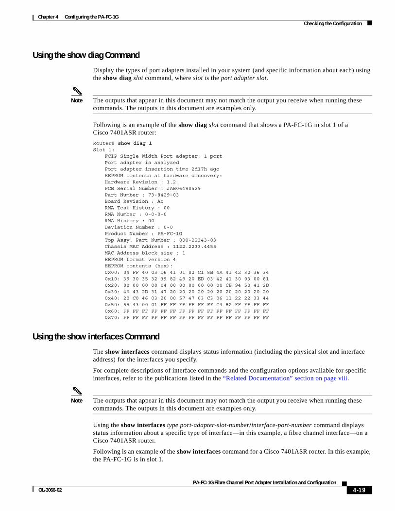
Using the show diag Command
Display the types of port adapters installed in your system (and specific information about each) using the show diag slot command, where slot is the port adapter slot.
Note The outputs that appear in this document may not match the output you receive when running these commands. The outputs in this document are examples only.
Following is an example of the show diag slot command that shows a PA-FC-1G in slot 1 of a Cisco 7401ASR router:
Router# show diag 1Slot 1:
FCIP Single Width Port adapter, 1 port Port adapter is analyzed Port adapter insertion time 2d17h ago EEPROM contents at hardware discovery: Hardware Revision : 1.2 PCB Serial Number : JAB06490529 Part Number : 73-8429-03 Board Revision : A0 RMA Test History : 00 RMA Number : 0-0-0-0 RMA History : 00 Deviation Number : 0-0 Product Number : PA-FC-1G Top Assy. Part Number : 800-22343-03 Chassis MAC Address : 1122.2233.4455 MAC Address block size : 1 EEPROM format version 4 EEPROM contents (hex): 0x00: 04 FF 40 03 D6 41 01 02 C1 8B 4A 41 42 30 36 34 0x10: 39 30 35 32 39 82 49 20 ED 03 42 41 30 03 00 81 0x20: 00 00 00 00 04 00 80 00 00 00 00 CB 94 50 41 2D 0x30: 46 43 2D 31 47 20 20 20 20 20 20 20 20 20 20 20 0x40: 20 C0 46 03 20 00 57 47 03 C3 06 11 22 22 33 44 0x50: 55 43 00 01 FF FF FF FF FF FF C4 82 FF FF FF FF 0x60: FF FF FF FF FF FF FF FF FF FF FF FF FF FF FF FF 0x70: FF FF FF FF FF FF FF FF FF FF FF FF FF FF FF FF
Using the show interfaces Command
The show interfaces command displays status information (including the physical slot and interface address) for the interfaces you specify.
For complete descriptions of interface commands and the configuration options available for specific interfaces, refer to the publications listed in the “Related Documentation” section on page viii.
Note The outputs that appear in this document may not match the output you receive when running these commands. The outputs in this document are examples only.
Using the show interfaces type port-adapter-slot-number/interface-port-number command displays status information about a specific type of interface—in this example, a fibre channel interface—on a Cisco 7401ASR router.
Following is an example of the show interfaces command for a Cisco 7401ASR router. In this example, the PA-FC-1G is in slot 1.
4-19PA-FC-1G Fibre Channel Port Adapter Installation and Configuration
OL-3066-02

Chapter 4 Configuring the PA-FC-1GChecking the Configuration
Router# show interfaces fcpa 1/0Fcpa1/0 is up, line protocol is up Hardware is FC over TCP/IP Internet address is 10.1.1.1/8 MTU 1500 bytes, BW 1000000 Kbit, DLY 10 usec, reliability 255/255, txload 195/255, rxload 17/255 Encapsulation ARPA, loopback not set Full-duplex, 1000Mb/s, media type is unknown 0 output flow-control is unsupported, input flow-control is unsupported ARP type: ARPA, ARP Timeout 04:00:00 Last input never, output 00:00:02, output hang never Last clearing of "show interface" counters never Input queue: 0/75/233/0 (size/max/drops/flushes); Total output drops: 0 Queueing strategy: fifo Output queue :0/40 (size/max) 5 minute input rate 2122360000 bits/sec, 44192148 packets/sec 5 minute output rate 18200000 bits/sec, 20181 packets/sec 0 packets input, 0 bytes, 0 no buffer Received 0 broadcasts, 0 runts, 0 giants, 0 throttles 0 input errors, 0 CRC, 0 frame, 0 overrun, 233 ignored, 0 abort 0 watchdog, 0 multicast, 0 pause input 99 packets output, 5940 bytes, 0 underruns 0 output errors, 0 collisions, 13 interface resets 0 output buffer failures, 0 output buffers swapped outRouter#
Using the ping Command to Verify Network ConnectivityUsing the ping command, you can verify that an interface port is functioning properly. This section provides a brief description of this command. Refer to the publications listed in the “Related Documentation” section on page viii for detailed command descriptions and examples.
The ping command sends echo request packets out to a remote device at an IP address that you specify. After sending an echo request, the system waits a specified time for the remote device to reply. Each echo reply is displayed as an exclamation point (!) on the console terminal; each request that is not returned before the specified timeout is displayed as a period (.). A series of exclamation points (!!!!!) indicates a good connection; a series of periods (.....) or the messages [timed out] or [failed] indicate a bad connection.
Following is an example of a successful ping command to a remote server with the address 10.0.0.10:
Router# ping 10.0.0.10 <Return>Type escape sequence to abort.Sending 5, 100-byte ICMP Echoes to 10.0.0.10, timeout is 2 seconds:!!!!!Success rate is 100 percent (5/5), round-trip min/avg/max = 1/15/64 msRouter#
If the connection fails, verify that you have the correct IP address for the destination and that the device is active (powered on), and repeat the ping command.
Pinging the PA-FC-1G
After the PA-FC-1G is enabled using the no shut command, pinging the PA-FC-1G IP address should be successful. Pinging the TCP tunnel source and destination IP addresses is successful only after the TCP tunnel has been brought into service using the inservice command.
4-20PA-FC-1G Fibre Channel Port Adapter Installation and Configuration
OL-3066-02
Chapter 4 Configuring the PA-FC-1GTroubleshooting
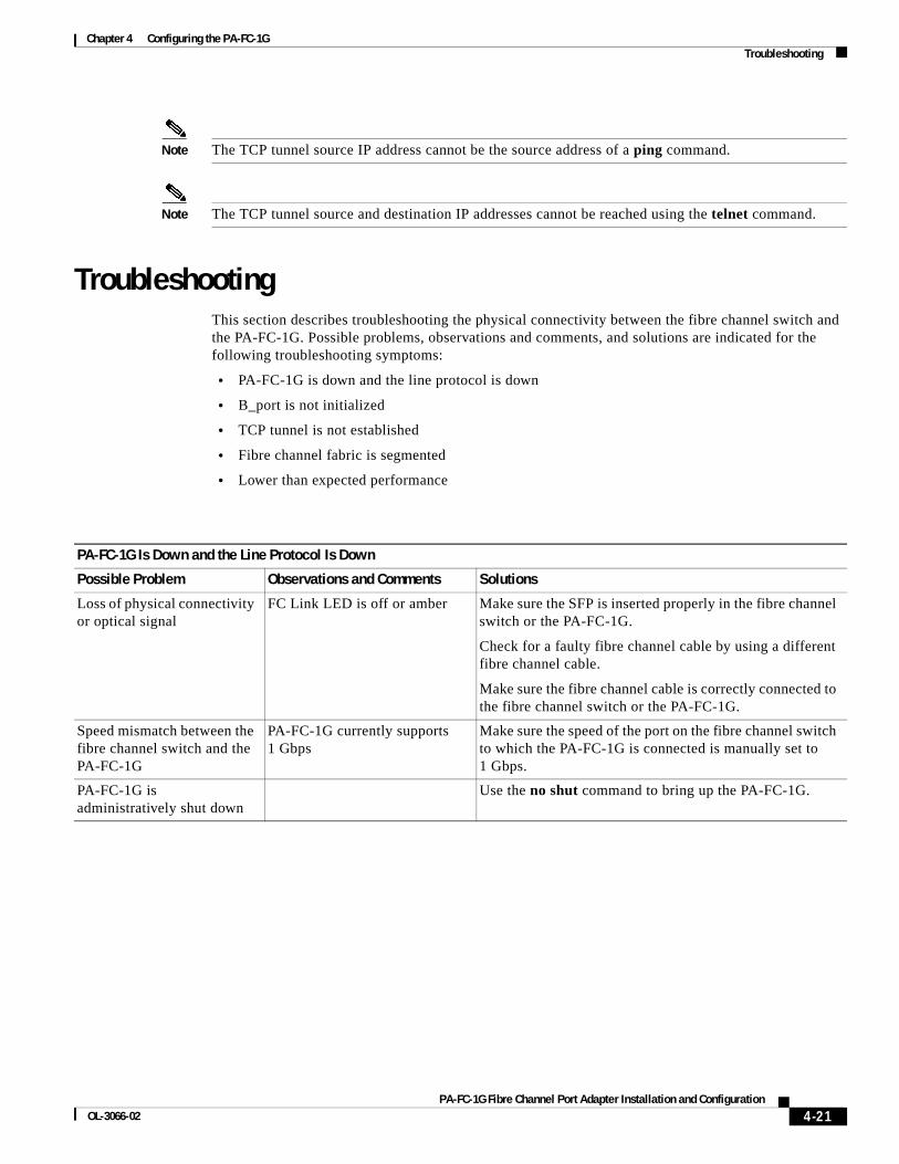
Note The TCP tunnel source IP address cannot be the source address of a ping command.
Note The TCP tunnel source and destination IP addresses cannot be reached using the telnet command.
TroubleshootingThis section describes troubleshooting the physical connectivity between the fibre channel switch and the PA-FC-1G. Possible problems, observations and comments, and solutions are indicated for the following troubleshooting symptoms:
• PA-FC-1G is down and the line protocol is down
• B_port is not initialized
• TCP tunnel is not established
• Fibre channel fabric is segmented
• Lower than expected performance
PA-FC-1G Is Down and the Line Protocol Is Down
Possible Problem Observations and Comments Solutions
Loss of physical connectivity or optical signal
FC Link LED is off or amber Make sure the SFP is inserted properly in the fibre channel switch or the PA-FC-1G.
Check for a faulty fibre channel cable by using a different fibre channel cable.
Make sure the fibre channel cable is correctly connected to the fibre channel switch or the PA-FC-1G.
Speed mismatch between the fibre channel switch and the PA-FC-1G
PA-FC-1G currently supports 1 Gbps
Make sure the speed of the port on the fibre channel switch to which the PA-FC-1G is connected is manually set to 1 Gbps.
PA-FC-1G is administratively shut down
Use the no shut command to bring up the PA-FC-1G.
4-21PA-FC-1G Fibre Channel Port Adapter Installation and Configuration
OL-3066-02
Chapter 4 Configuring the PA-FC-1GTroubleshooting
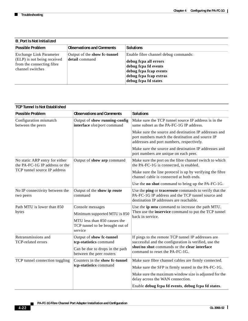
B_Port Is Not Initialized
Possible Problem Observations and Comments Solutions
Exchange Link Parameter (ELP) is not being received from the connecting fibre channel switches
Output of the show fc-tunnel detail command
Enable fibre channel debug commands:
debug fcpa all errorsdebug fcpa fd eventsdebug fcpa fcap eventsdebug fcpa fcap extrasdebug fcpa fd states
TCP Tunnel Is Not Established
Possible Problem Observations and Comments Solutions
Configuration mismatch between the peers
Output of show running-config interface slot/port command
Make sure the TCP tunnel source IP address is in the same subnet as the PA-FC-1G IP address.
Make sure the source and destination IP addresses and port numbers match the destination and source IP addresses and port numbers, respectively.
Make sure the source and destination IP addresses and port numbers are unique on each peer.
No static ARP entry for either the PA-FC-1G IP address or the TCP tunnel source IP address
Output of show arp command Make sure the port on the fibre channel switch to which the PA-FC-1G is connected, is enabled.
Make sure the line protocol is up by verifying the fibre channel cable is connected at both ends.
Use the no shut command to bring up the PA-FC-1G.
No IP connectivity between the two peers
Output of the show ip route command
Use the ping or traceroute commands to verify that the PA-FC-1G IP address and the TCP tunnel source and destination IP addresses are reachable.
Path MTU is lower than 850 bytes
Console messages
Minimum supported MTU is 850
MTU less than 850 causes the TCP tunnel to be brought out of service
Use the ip mtu command to increase the path MTU. Then use the inservice command to put the TCP tunnel back in service.
Retransmissions and TCP-related errors
Output of show fc-tunnel tcp-statistics command
Can be due to drops in the path between the peer routers
If pings to the remote TCP tunnel IP addresses are successful and the configuration is verified, use the shut/no shut commands or the clear interface command to reset the PA-FC-1G.
TCP tunnel connection toggling Counters in the show fc-tunnel tcp-statistics command
Make sure fibre channel cables are firmly connected.
Make sure the SFP is firmly seated in the PA-FC-1G.
Make sure the maximum window size is adjusted for the delay across the WAN connection.
Enable debug fcpa fd events, debug fcpa fd states.
4-22PA-FC-1G Fibre Channel Port Adapter Installation and Configuration
OL-3066-02
Chapter 4 Configuring the PA-FC-1GTroubleshooting
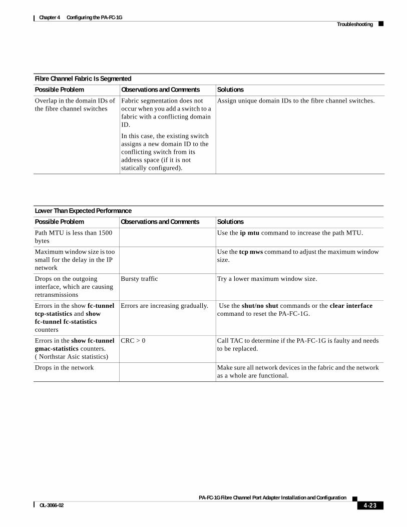
Fibre Channel Fabric Is Segmented
Possible Problem Observations and Comments Solutions
Overlap in the domain IDs of the fibre channel switches
Fabric segmentation does not occur when you add a switch to a fabric with a conflicting domain ID.
In this case, the existing switch assigns a new domain ID to the conflicting switch from its address space (if it is not statically configured).
Assign unique domain IDs to the fibre channel switches.
Lower Than Expected Performance
Possible Problem Observations and Comments Solutions
Path MTU is less than 1500 bytes
Use the ip mtu command to increase the path MTU.
Maximum window size is too small for the delay in the IP network
Use the tcp mws command to adjust the maximum window size.
Drops on the outgoing interface, which are causing retransmissions
Bursty traffic Try a lower maximum window size.
Errors in the show fc-tunnel tcp-statistics and show fc-tunnel fc-statistics counters
Errors are increasing gradually. Use the shut/no shut commands or the clear interface command to reset the PA-FC-1G.
Errors in the show fc-tunnel gmac-statistics counters. ( Northstar Asic statistics)
CRC > 0 Call TAC to determine if the PA-FC-1G is faulty and needs to be replaced.
Drops in the network Make sure all network devices in the fabric and the network as a whole are functional.
4-23PA-FC-1G Fibre Channel Port Adapter Installation and Configuration
OL-3066-02

Chapter 4 Configuring the PA-FC-1GTroubleshooting
Debug CommandsThere are many debug command options to review the status of the PA-FC-1G. The debug command has the format debug fcpa {module} {submodule}
• Module options
– all: all modules
– cli: command line interface — PA-FC-1G interface configuration commands
– cordova-driver: Gigabit Ethernet driver that interfaces with PA-FC-1G GMAC
– fcap: fibre channel application — module that maintains the B_port state machine
– fd: fibre channel frame distributor module that provides services to fcap and checks TCP connection status periodically
– northstar-driver: driver that interfaces with Northstar ASIC and provides services to fibre channel and TCP
– sm: session manager, the module responsible for TCP connection, configuration, and timer management
– tcp: TCP library
• Submodule options
– all: all submodules
– errors: errors that occurred in the selected module
– events: specific events information in the selected module
– extra: not generally required, quite verbose
– packets: packets handled by the selected module
– states: information for the fibre channel, session manager, and TCP states
Note Under heavy traffic, do not enable debug fcpa cordova-driver packets, debug fcpa northstar-driver events, or debug fcpa northstar-driver extra. These debug commands degrade performance and make the console unusable.
4-24PA-FC-1G Fibre Channel Port Adapter Installation and Configuration
OL-3066-02