conformance test specifications for wireless access in ... · pdf filevehicular environments...
TRANSCRIPT

Conformance test specifications for Wireless Access in
Vehicular Environments (WAVE) — Networking Services
Test Suite Structure and Test Purposes (TSS & TP)
Document Mnemonics: WAVENS-TSS&TP
Revision: [V1.0]
Revision Date: 3/29/2016
WAVENS-TSS&TP V1.0 (3/29/2016)
Connected Vehicle Certification Operating Council Page 2 of 53
Table of Contents
1 Scope ..................................................................................................................................................... 4
2 References ............................................................................................................................................. 4
2.1 Normative References .................................................................................................................. 4
2.2 Informative References ................................................................................................................ 4
3 Definitions and Abbreviations ................................................................................................................. 5
3.1 Definitions ..................................................................................................................................... 5
3.2 Abbreviations .......................................................................................................................................... 5
4 Prerequisites and Test Configurations ................................................................................................... 5
4.1 Test Configurations ...................................................................................................................... 5
4.1.1 Global Test Parameters .................................................................................................. 6 4.2 Feature Restriction and Behavior Description.............................................................................. 8
4.2.1 Feature Restriction .......................................................................................................... 8 4.3 Rules for the Behavior Description ............................................................................................... 8
4.3.1 Conditions for the Initial State ......................................................................................... 9
5 Test Suite Structure (TSS) ..................................................................................................................... 9
5.1 Structure for Network Services Tests ........................................................................................... 9
5.1.1 Root ................................................................................................................................. 9 5.1.2 Groups ........................................................................................................................... 10 5.1.3 Sub-Groups ................................................................................................................... 10 5.1.4 Categories ..................................................................................................................... 10
6 Test Purposes (TP) .............................................................................................................................. 10
6.1 Introduction ................................................................................................................................. 10
6.1.1 TP definition conventions .............................................................................................. 10 6.1.2 TP Identifier Naming Conventions................................................................................. 11 6.1.3 Naming Convention for Variants ................................................................................... 11 6.1.4 References .................................................................................................................... 11 6.1.5 PICS selection and mnemonics for reference ............................................................... 11 6.1.6 Sources of TP definitions .............................................................................................. 12
6.2 Test Purposes for 1609.3 ........................................................................................................... 13
6.2.1 WSM packet validation .................................................................................................. 13 6.2.2 WSM transmission parameters ..................................................................................... 14 6.2.3 Reception of WSMs ....................................................................................................... 15 6.2.4 WSM communications with continuous channel access ............................................... 17 6.2.5 WSM communications with alternating channel access ............................................... 18 6.2.6 Transmission of WSMs with payload exceeding WsmMaxLength ................................ 20

WAVENS-TSS&TP V1.0 (3/29/2016)
Connected Vehicle Certification Operating Council Page 3 of 53
6.2.7 WSA packet validation .................................................................................................. 20 6.2.8 WSA reception............................................................................................................... 26 6.2.9 WSA transmission parameters ...................................................................................... 29 6.2.10 WSA changes ................................................................................................................ 30 6.2.11 IP Configuration ............................................................................................................. 31 6.2.12 Changing IP configuration ............................................................................................. 32 6.2.13 Communication using IPv6 ............................................................................................ 33
7 Messages and Information Element Contents ..................................................................................... 35
7.1 WAVE Short Messages .............................................................................................................. 35
7.1.1 Message defaults .......................................................................................................... 35 7.1.2 Message details............................................................................................................. 35
7.2 WAVE Service Advertisement (WSA) ........................................................................................ 36
7.2.1 Message defaults .......................................................................................................... 36 7.2.2 Message details............................................................................................................. 36
Appendix A: Traceability Matrix .................................................................................................................. 45
Revision History .......................................................................................................................................... 52

WAVENS-TSS&TP V1.0 (3/29/2016)
Connected Vehicle Certification Operating Council Page 4 of 53
1 Scope
This document provides the Test Suite Structure and Test Purposes for WAVE Network Services (WNS) as defined in IEEE 1609.3 [2]. The document defines a set of Test Purposes including Test Descriptions and the structure for the Test Suite.
The ISO standard for the methodology of conformance testing (ISO/IEC 9646-1 [3] and ISO/IEC 9646-2 [4]) as well as the ETSI rules for conformance testing (ETS 300 406 [7]) are used as a basis for the test methodology.
2 References
2.1 Normative References
The following referenced documents are necessary for the application of the present document.
[1] SAE J2945/1 Draft 5.0 (December 2015): “On-board System Requirements for V2V Safety Communications”.
[2] IEEE Std 1609.3-2016 “IEEE Standard for Wireless Access in Vehicular Environments (WAVE) — Network Services”.
[3] ISO/IEC 9646-1 (1994): "Information technology -- Open Systems Interconnection -- Conformance testing methodology and framework - Part 1: General concepts".
[4] ISO/IEC 9646-2 (1994): "Information technology -- Open Systems Interconnection -- Conformance testing methodology and framework -- Part 2: Abstract Test Suite specification".
[5] IEEE Std. 1609.12-2016 “IEEE Standard for Wireless Access in Vehicular Environments – Identifier Allocations”.
[6] ISO/IEC 9646-7 (1995): "Information technology -- Open Systems Interconnection -- Conformance testing methodology and framework - Part 7: Implementation Conformance Statements".
[7] ETSI ETS 300 406 (1995): "Methods for testing and Specification (MTS); Protocol and profile conformance testing specifications; Standardization methodology".
[8] IEEE Std. 1609.2-2016: "IEEE Draft Standard for Wireless Access in Vehicular Environments - security Services for Applications and Management Messages".
[9] IETF RFC 4862, IPv6 Stateless Address Configuration.
[10] IEEE Std. 1609.4-2016 “IEEE Standard for Wireless Access in Vehicular Environments (WAVE) -- Multi-Channel Operation”.
2.2 Informative References
The following referenced documents are not necessary for the application of the present document but they assist the user with regard to a particular subject area.
[i.1] ETSI EG 202 798 (V1.1.1): "Intelligent Transport Systems (ITS); Testing; Framework for conformance and interoperability testing".

WAVENS-TSS&TP V1.0 (3/29/2016)
Connected Vehicle Certification Operating Council Page 5 of 53
3 Definitions and Abbreviations
3.1 Definitions
For the purposes of the present document, the terms and definitions given in IEEE 1609.3 [2], ISO/IEC 9646-1 [3] and in ISO/IEC 9646-7 [6] apply.
3.2 Abbreviations
For the purposes of the present document, the following abbreviations apply:
BI Behavior Invalid BSM Basic Safety Message BV Behavior Valid CH[#] Operating Channel CCH Control Channel DSRC Dedicated Short Range Communication EIRP Equivalent Isotropically Radiated Power ICMP Internet Control Message Protocol IETF Internet Engineering Task Force ITS Intelligent Transport Systems IUT Implementation Under Test PDU Protocol Data Unit PICS Protocol Implementation Conformance Statement PSID Provider Service Identifier SCH Service Channel SUT System Under Test TAI International Atomic Time TC Test Configuration TP Test Purposes TS Test System TSS Test Suite Structure WAVE Wireless Access in Vehicular Environments WME WAVE Management Entity WNS WAVE Network Services WRA WAVE Routing Advertisement WSA WAVE Service Advertisement WSM WAVE Short Message SAP Service Access Point TSF Timing Synchronization Function
4 Prerequisites and Test Configurations
4.1 Test Configurations
This clause introduces the test configurations that is used for the definition of test purposes. The test configurations cover the various scenarios of the WAVE Network Services (WNS) tests.

WAVENS-TSS&TP V1.0 (3/29/2016)
Connected Vehicle Certification Operating Council Page 6 of 53
Figure 4-1 Test Configuration 1 (TC1) – Sending/Receiving WSMs
The Test Configuration 1 as shown in Figure 4-1is applied for the test tests dealing with transmission and reception of WAVE Short Messages (WSM).
Figure 4-2 Test Configuration 2 (TC2) – IPv6 Host Communications
The Test Configuration 2 as shown in Figure 4-2 is applied for the communication test group dealing with exchange between IUT and IP host using IPv6 protocol. TC2 depicts an IP host connected to the WAVE host via a wired Ethernet link with the corresponding routing tables established to facilitate two-way packet exchanges between the IUT and the IP host.
4.1.1 Global Test Parameters
Below are listed global test parameters / conditions that are applicable to all test cases in this specification.
4.1.1.1 Channels
Select test values for Channel specified using vChannel according to the following table:
Table 4-1: Channels Parameter name Range of permitted values Setting used for
testing Reference
Channel specified as vChannel
10MHz channels: 172, 174, 178, 180, 182, 184
172 [2]
Channels specified as CH1 and CH2
Perform test sequence with the following channel sets: CH1=178, CH2 = 174 CH1=174, CH2 = 178 CH1=178, CH2 = 178 CH1=174, CH2 = 174 CH1=172, CH2 = 184
[2]

WAVENS-TSS&TP V1.0 (3/29/2016)
Connected Vehicle Certification Operating Council Page 7 of 53
For those TPs where tests must be repeated using different channels defined by vChannel, set vChannel consecutively to values 172, 178, 182, and 184.
4.1.1.2 Data Rate
Select test values for Data Rate specified using vDataRate according to the following table.
Table 4-2: Data Rates Parameter name Range of permitted values Setting used for
testing Reference
Data Rate (Mbps) 3, 4.5, 6, 9, 12, 18, 24, 27 6 [2] If test require repetition using different data rates, use the following discrete values 3, 6, 12, 27Mbps
4.1.1.3 Transmit Power
Select test values for Transmit Power specified using vTxPower according to the following table.
Table 4-3: Transmit Power Parameter name Range of permitted values Setting used for
testing1 Reference
Transmit Power (dBm) Min Transmit Power: -92 Max Transmit Power (EIRP): Class A: 23 Class B: 23 Class C: 33 Class D: 33 – non-government use 44.8 – government use
20 Default setting selected according to [1]
If test must be repeated using different values of vTxPower, the following discrete settings will be used (dBm): 10, 12, 14, 16, 18, 20. These values selected from [1] clause 6.4.1.1.
4.1.1.4 PSID
Select test values for PSID specified using vPSID according to the following table.
Table 4-4: PSID Parameter name Range of permitted values (p-encoded) Setting used for
testing Reference
PSID 1byte PSID: 0p00 to 0p7F 2byte PSID: 0p80-00 to 0pBF-FF 3byte PSID: 0pC0-00-00 to 0pDF-FF-FF 4byte PSID: 0pE0-00-00-00 to 0pEF-FF-FF-FF
0p7F 0pBF-FF 0pDF-FF-FF 0pEF-FF-FF-FF
[5]
PSID1 PSID2
0p7F 0pBF-FF
[5]
PSID for WSA WAVE Sec Mgmt BSM IP routing
0p80-07 0p23 0p20 0pEF-FF-FF-FE
[5]
4.1.1.5 WSM Max Data Length
Set the value for WsmMaxDataLength to 1400 bytes 1 Specified transmit power setting may be higher than acceptable receiver input and cause damage to the receiver. Use of an attenuator may be warranted to protect receiver input circuits.

WAVENS-TSS&TP V1.0 (3/29/2016)
Connected Vehicle Certification Operating Council Page 8 of 53
4.1.1.6 Transmission Repeat Rates
Select test values for message repeat rates according to the following table.
Table 4-5: Repeat Rate Parameter name Range of permitted
values (msg/sec) Setting used for
testing (msg/sec) Reference
Repeat Rate for WSA transmissions (vWSARepeatRate)
0 – 51 10 Recommended practice
Repeat Rate for WSM transmissions (vWSMRepeatRate)
0 – 51 10 Recommended practice
4.1.1.7 Average Repeat Rates for Received Messages
Use the following method to determine the Repeat Rate Average (RRAvg) and the Repeat Rate Standard Deviation (RRStdDev) for a sample received messages:
Record reception times for n messages as Tn, where n = 100
Calculate AvgRR = n
Tn∑∆ )( , where 1)( −−=∆ nnn TTT
Calculate RRStdDev= 1
)( 2
−−∑n
AvgRRTn
Calculate vWSMRepeatPeriod = 1 / vWSMRepeatRate
Calculate vWSARepeatPeriod = 1 / vWSARepeatRate
4.2 Feature Restriction and Behavior Description
4.2.1 Feature Restriction
In this clause all feature restrictions are listed:
• Multi-radio devices are not considered • 20MHz channels are not considered in the scope of this document • Testing for other IETF protocols except ICMPv6 is not considered • Immediate access or extended access to communication media is not considered • No testing for Channel Load • No testing for TSF messages • Only signed WSAs are considered • Multicast IPv6 is not tested • Testing for the SAP defined in [2] is not considered
4.3 Rules for the Behavior Description
The description of the TP is built according to EG 202 798 [i.1].
Test purposes use a generic "Initial State" that corresponds to a state where the IUT is ready for starting the test execution. Furthermore, the IUT shall be left in this "Initial State", when the test is completed.
Being in the "Initial State" refers to the starting point of the initial device configuration. There are no pending actions, no instantiated buffers or variables, which could disturb the execution of a test.

WAVENS-TSS&TP V1.0 (3/29/2016)
Connected Vehicle Certification Operating Council Page 9 of 53
4.3.1 Conditions for the Initial State
Overall state diagram for a test system is shown below.
Most of the TPs start from the “initial state” which is defined as follows:
• The IUT is powered up • Radio interface is initialized but does not transmit or receive messages over any DSRC channels • MAC address is assigned to the DSRC interface • The IUT is not exchanging any IP traffic • The IUT is provisioned with any required security credentials to enable transmission or reception of
messages over DSRC
Some TPs may from a different initial condition. Initial conditions required for specific test cases defined in the Initial condition section of a Test Purpose. However, the “initial state” defined above is the starting point before the different initial conditions are established.
When execution of the initial condition does not succeed, it leads to the assignment of an Inconclusive verdict.
5 Test Suite Structure (TSS)
5.1 Structure for Network Services Tests
The test suite is structured as a tree with the root defined as 16093. The tree is of rank 3 with the first rank a Group, the second a Sub-group, and the third a category. The third rank is the standard ISO conformance test categories.
5.1.1 Root
The root identifies the 1609.3 protocol given in IEEE 1609.3 [2].
State 2
IUT is in “Initial State”
State 1
IUT is powered off
State 3 Test Purpose Initial Conditions/Pre-test
Conditions
State 4 Test Execution
WAVENS-TSS&TP V1.0 (3/29/2016)
Connected Vehicle Certification Operating Council Page 10 of 53
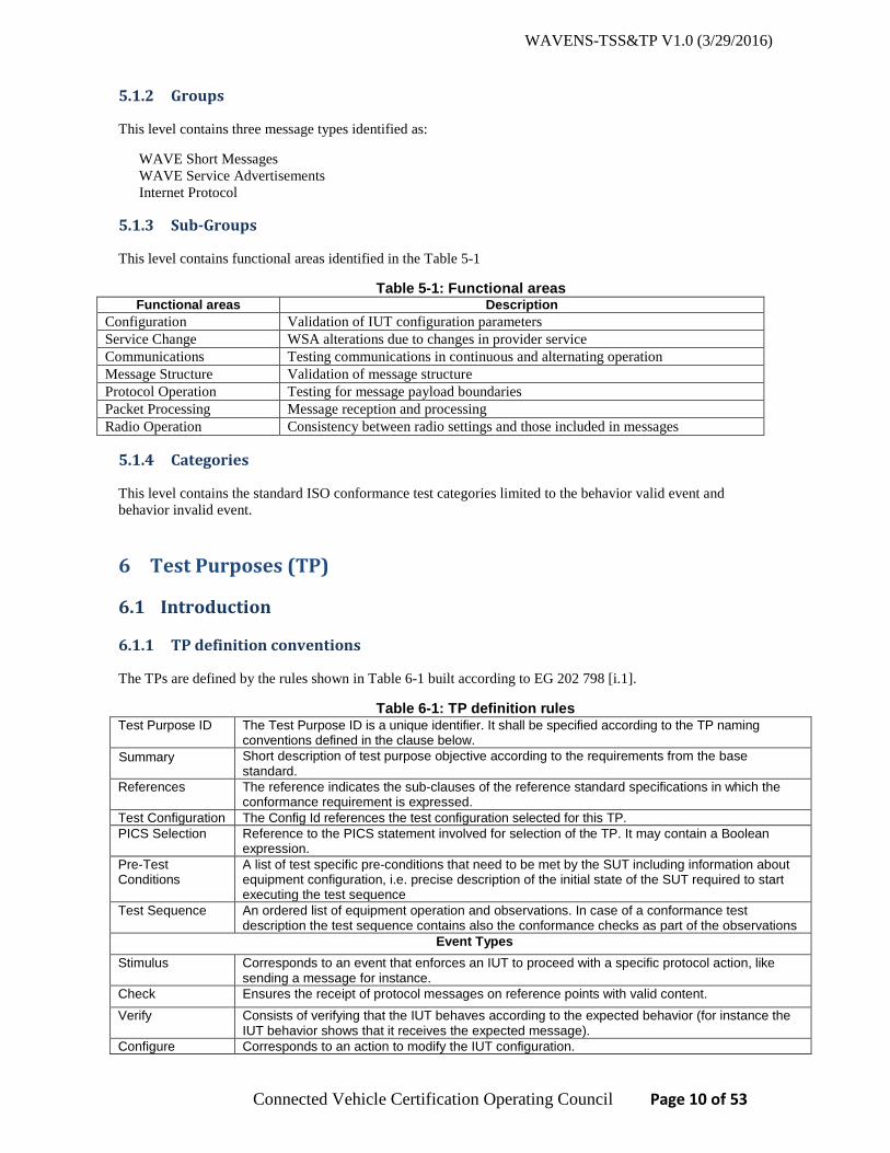
5.1.2 Groups
This level contains three message types identified as:
WAVE Short Messages WAVE Service Advertisements Internet Protocol
5.1.3 Sub-Groups
This level contains functional areas identified in the Table 5-1
Table 5-1: Functional areas Functional areas Description
Configuration Validation of IUT configuration parameters Service Change WSA alterations due to changes in provider service Communications Testing communications in continuous and alternating operation Message Structure Validation of message structure Protocol Operation Testing for message payload boundaries Packet Processing Message reception and processing Radio Operation Consistency between radio settings and those included in messages
5.1.4 Categories
This level contains the standard ISO conformance test categories limited to the behavior valid event and behavior invalid event.
6 Test Purposes (TP)
6.1 Introduction
6.1.1 TP definition conventions
The TPs are defined by the rules shown in Table 6-1 built according to EG 202 798 [i.1].
Table 6-1: TP definition rules Test Purpose ID The Test Purpose ID is a unique identifier. It shall be specified according to the TP naming
conventions defined in the clause below. Summary Short description of test purpose objective according to the requirements from the base
standard. References The reference indicates the sub-clauses of the reference standard specifications in which the
conformance requirement is expressed. Test Configuration The Config Id references the test configuration selected for this TP. PICS Selection
Reference to the PICS statement involved for selection of the TP. It may contain a Boolean expression. Pre-Test
Conditions A list of test specific pre-conditions that need to be met by the SUT including information about equipment configuration, i.e. precise description of the initial state of the SUT required to start executing the test sequence
Test Sequence An ordered list of equipment operation and observations. In case of a conformance test description the test sequence contains also the conformance checks as part of the observations
Event Types Stimulus Corresponds to an event that enforces an IUT to proceed with a specific protocol action, like
sending a message for instance. Check Ensures the receipt of protocol messages on reference points with valid content. Verify Consists of verifying that the IUT behaves according to the expected behavior (for instance the
IUT behavior shows that it receives the expected message). Configure Corresponds to an action to modify the IUT configuration.

WAVENS-TSS&TP V1.0 (3/29/2016)
Connected Vehicle Certification Operating Council Page 11 of 53
Procedure Procedural action directing the flow of TP execution.
6.1.2 TP Identifier Naming Conventions
TP identifiers are built according to Table 6-2.
Table 6-2: TP naming convention
Identifier TP-<root>-<gr>-<sgr>-<x>-<nn>
or TP-<root>-<gr>-<x>-<nn>
when no <sgr>
<root> = root 16093 <gr> = group WSM WAVE Short Messages WSA WAVE Service Advertisements IP Internet Protocol <sgr> =sub- group CFG Configuration CHG Service Change COM Communications MST Message Structure POP Protocol Operation PP Packet Processing ROP Radio Operation <x> = type of testing BV Valid Behavior tests BI Invalid Syntax or Behavior Tests <nn> = sequential number 01 to 99
6.1.3 Naming Convention for Variants
Some TPs use the concept of variants to provide more concise description. Their definition, how they are used and their naming conventions are defined in this clause.
In case where for a single parameter multiple values can be tested, then a table is appended after the TP. This table lists all the different value which need to be tested. The TP identifier is appended with –X (e.g. TP-16093-WSA-MST-BV-04-X). If there are fields for which multiple values can be tested then X is appended. The field itself is written as X_FIELD_NAME (e.g. X_WAVE_Element_ID).
Any TP which contains variants must be repeated for all values of X enabled by appropriate selection of PICS identified for an IUT in the PICS proforma.
6.1.4 References
All Test Purposes are derived from requirements defined in [2]. Traceability between TPs and sub-clauses of referenced standard specifications is established in the Table A- 1. For each PICS, a reference section from [2] is listed and an applicable test purposes are identified in the TP ID column.
6.1.5 PICS selection and mnemonics for reference
Table A- 1 includes a complete list of PICS defined in [2] with a traceability to TPs included in the TP ID column.
Table 6-3 lists mnemonic names and maps them to a subset of PICS item number. This is a partial list of PICS used in selecting of certain TPs or TPs which incorporated variances.

WAVENS-TSS&TP V1.0 (3/29/2016)
Connected Vehicle Certification Operating Council Page 12 of 53
Table 6-3: Mnemonics for PICS reference
Mnemonic
PICS item PIC_ChannelNumber
[2] Annex D, N1.3.2.4.
PIC_DataRate [2] Annex D, N1.3.2.5. PIC_TransmitPowerUser [2] Annex D, N1.3.2.6. PIC_URepeatRate [2] Annex D, N2.1.6.4.1. PIC_U2DLocation [2] Annex D, N2.1.6.4.2. PIC_U3DLocation [2] Annex D, N2.1.6.4.3. PIC_UAdvertiserId [2] Annex D, N2.1.6.4.4. PIC_UPSC [2] Annex D, N2.1.7.2.1. PIC_UIPV6Address [2] Annex D, N2.1.7.2.2. PIC_UServicePort [2] Annex D, N2.1.7.2.3. PIC_UProviderMACAddress [2] Annex D, N2.1.7.2.4. PIC_URCPIThreshold [2] Annex D, N2.1.7.2.5. PIC_UWSACountThreshold [2] Annex D, N2.1.7.2.6. PIC_UWSACountThresholdInt [2] Annex D, N2.1.7.2.6.1. PIC_UChannelAccess [2] Annex D, N2.1.8.2.2. PIC_UEDCAParamSet [2] Annex D, N2.1.8.2.1. PIC_USecondaryDNS [2] Annex D, N2.1.9.1.1. PIC_UGatewayMACAddress [2] Annex D, N2.1.9.1.2. PIC_PRepeatRate [2] Annex D, N2.2.6.1. PIC_P2DLocation [2] Annex D, N2.2.6.2. PIC_P3DLocation [2] Annex D, N2.2.6.3. PIC_PAdvertiserId [2] Annex D, N2.2.6.4. PIC_PPSC [2] Annex D, N2.2.9.1. PIC_PIPV6Address [2] Annex D, N2.2.9.2. PIC_PServicePort [2] Annex D, N2.2.9.3. PIC_PProviderMACAddress [2] Annex D, N2.2.9.4. PIC_PRCPIThreshold [2] Annex D, N2.2.9.5. PIC_PWSACountThreshold [2] Annex D, N2.2.9.6. PIC_PWSACountThresholdInt [2] Annex D, N2.2.9.6.1. PIC_PChannelAccess [2] Annex D, N2.2.12.2. PIC_PEDCAParamSet [2] Annex D, N2.2.12.1. PIC_PSecondaryDNS [2] Annex D, N2.2.13.1.1. PIC_PGatewayMACAddress [2] Annex D, N2.2.13.1.2.
6.1.6 Sources of TP definitions
All TPs are specified according to IEEE 1609.3 [2]. Traceability from PICS to TPs is included in the Appendix A.
The Appendix A includes a full list of PICs from IEEE 1609.3. SAE J2945/1 [1] uses a subset of PICS from IEEE 1609.3. Those PICS are identified with status V2V and SCMS. The remaining PICS excluded from the SAE J2945/1 are identified with the status RSE.

WAVENS-TSS&TP V1.0 (3/29/2016)
Connected Vehicle Certification Operating Council Page 13 of 53
6.2 Test Purposes for 1609.3
6.2.1 WSM packet validation
Identifier TP-16093-WSM-MST-BV-01 Summary To verify that the IUT will transmit a WSM with the correct version number and
EtherType. Test Configuration TC1 IUT IUT Reference: PICS Selection
Pre-test conditions • The IUT is in the initial state
Test Sequence Step Type Description Verdict
1 Configure The IUT is configured to transmit WSM_without_nExt in Table 7-1. 2 Stimulus The IUT transmits WSM 3 Verify The IUT transmitted WSM Pass/Fail 4 Verify WSM is included in 802.11 frame, containing Logical-Link Control
section, containing Type field indicating EtherType value 0x88DC. Pass/Fail
5 Verify WSM-N-Header/Subtype containing WSMP Version indicating ‘3’ Pass/Fail 6 Procedure Repeat steps 1-5 for WSM_nExt in Table 7-2.
Identifier TP-16093-WSM-MST-BV-02 Summary Verify that the IUT will transmit WSM containing valid WSM-T-Header, containing PSID
and WSM Data. Test Configuration TC1 IUT IUT Reference: PICS Selection
Pre-test conditions • The IUT is in the initial state
Test Sequence Step Type Description Verdict
1 Configure The IUT is configured to transmit WSM_without_nExt in Table 7-1. with ‘vPSID’ and the ‘WSM Payload’ length equal vWSM_Length
2 Stimulus The IUT transmits WSM 3 Verify The IUT transmitted WSM Pass / Fail 4 Verify WSM N-Header contains ‘TPID’ indicating ‘0’ Pass / Fail 5 Verify WSM T-Header contains ‘ProviderServiceIdentifier’ indicating
‘vPSID’ Pass / Fail
6 Verify WSM T-Header does not contain ‘WAVE Information Elements’ Pass / Fail 7 Verify WSM Payload contains ‘WSMLength’, indicating the value equal to
vWSM_Length. Pass / Fail
8 Verify WSM Payload contains ‘WSMData’. The length of WSMData is equal to vWSM_Length
Pass / Fail
9 Procedure Repeat steps 1-8 for ‘vPSID’ with sizes 1,2,3 and 4 Bytes listed in Table 4-4.

WAVENS-TSS&TP V1.0 (3/29/2016)
Connected Vehicle Certification Operating Council Page 14 of 53
6.2.2 WSM transmission parameters
Identifier TP-16093-WSM-ROP-BV-01 Summary Verify that the IUT will transmit WSM containing valid WSM-N-Header including
WAVE Info Element Extension ‘Channel Number’ and matching the actual channel used by the IUT.
Test Configuration TC1 IUT IUT Reference: PICS Selection PIC_ChannelNumber
Pre-test conditions • The IUT is in the initial state
Test Sequence Step Type Description Verdict
1 Configure The IUT is configured to transmit WSM_nExt in Table 7-2 using channel ‘vChannel’ and include WAVE Element Extension fields ‘Channel Number’.
2 Stimulus The IUT transmits WSM 3 Verify The IUT transmitted WSM Pass / Fail 4 Verify WSM N-Header contains ‘Subtype’ indicating ‘0x0B’ Pass / Fail 5 Verify WSM N-Header contains ‘Wave Info Element’ contains ’Count’
matching the number of ‘Wave Info Element’ included in the message (>= 1, cannot be ‘0’)
Pass / Fail
6 Verify WSM N-Header contains ‘WAVE Info Element’ containing ‘WAVE Element ID’ indicating ‘15’ (Channel Number)
Pass / Fail
7 Verify WSM N-Header contains ‘WAVE Elem Length’ indicating ‘1’ Pass / Fail 8 Verify WSM N-Header contains ‘WAVE Elem’ data indicating the Channel
Number value equal to ‘vChannel’ Pass / Fail
9 Procedure Repeat steps 1-8 for other values of ‘vChannel’ listed in Section 4.1.1.1.
Identifier TP-16093-WSM-ROP-BV-02 Summary Verify that the IUT will transmit WSM containing valid WSM-N-Header including
WAVE Info Element Extension ‘Data Rate’ and matching the actual data rate used by the IUT.
Test Configuration TC1 IUT IUT Reference: PICS Selection PIC_DataRate
Pre-test conditions • The IUT is in the initial state
Test Sequence Step Type Description Verdict
1 Configure The IUT is configured to transmit WSM_nExt in Table 7-2 using ‘vDataRate’ and include WAVE Element Extension fields ‘Data Rate’
2 Stimulus The IUT transmits WSM 3 Verify The IUT transmitted WSM Pass / Fail 4 Verify WSM N-Header contains ‘Subtype’ indicating ‘0x0B’ Pass / Fail 5 Verify WSM N-Header contains ‘Wave Info Element’ containing ’Count’
matching the number of ‘Wave Info Element’ included in the message (>= 1, cannot be ‘0’)
Pass / Fail
6 Verify WSM N-Header contains ‘WAVE Info Element’ containing ‘WAVE Pass / Fail

WAVENS-TSS&TP V1.0 (3/29/2016)
Connected Vehicle Certification Operating Council Page 15 of 53
Element ID’ indicating ‘16’ (Data Rate) 7 Verify WSM N-Header contains ‘WAVE Elem Length’ indicating ‘1’ Pass / Fail 8 Verify WSM N-Header contains ‘WAVE Elem’ data indicating the Data Rate
value equal to ‘vDataRate’ Pass / Fail
9 Procedure Repeat steps 1-8 for other values of ‘vDataRate’ listed in Section 4.1.1.2.
Identifier TP-16093-WSM-ROP-BV-03 Summary Verify that the IUT will transmit WSM containing valid WSM-N-Header including WAVE
Info Element Extension ‘Transmit Power Used’ and matching the actual transmit power used by the IUT.
Test Configuration TC1 IUT IUT Reference: PICS Selection PIC_TransmitPowerUsed
Pre-test conditions • The IUT is in the initial state
Test Sequence Step Type Description Verdict
1 Configure The IUT is configured to transmit WSM_nExt in Table 7-2 using ‘vTxPower’ and include WAVE Element Extension fields ‘Transmit Power Used’
2 Stimulus The IUT transmits WSM 3 Verify The IUT transmitted WSM Pass / Fail 4 Verify WSM N-Header contains ‘Subtype’ indicating ‘0x0B’ Pass / Fail 5 Verify WSM N-Header contains ‘Wave Info Element’ containing ’Count’
matching the number of ‘Wave Info Element’ included in the message (>= 1, cannot be ‘0’)
Pass / Fail
6 Verify WSM N-Header contains ‘WAVE Info Element’ containing ‘WAVE Element ID’ indicating ‘4’ (Transmit Power Used)
Pass / Fail
7 Verify WSM N-Header contains ‘WAVE Elem Length’ indicating ‘1’ Pass / Fail 8 Verify WSM N-Header contains ‘WAVE Elem’ data indicating the Transmit
Power Used value equal to ‘vTxPower’. Pass / Fail
9 Procedure Repeat steps 1-8 for other values of ‘vTxPower’ listed in the Section 4.1.1.3
6.2.3 Reception of WSMs
Identifier TP-16093-WSM-PP-BV-01 Summary Verify that the IUT registered for a PSID service will receive a WSM containing valid WSM-
N-Header, valid WSM-T-Header, WSM Data field and excluding optional WAVE Info Element extensions.
Test Configuration TC1 IUT IUT Reference: PICS Selection
Pre-test conditions • The IUT is in the initial state • The WAVE Host is transmitting on a fixed channel ‘vChannel’ in continuous mode messages
WSM_without_nExt defined in Table 7-1 with a ‘vPSID’ Test Sequence
Step Type Description Verdict

WAVENS-TSS&TP V1.0 (3/29/2016)
Connected Vehicle Certification Operating Council Page 16 of 53
1 Configure IUT configured to received WSMs with ‘vPSID’ in continuous mode on channel ‘vChannel’
2 Check WSMs is detected on channel ‘vChannel’ 3 Check WSM N-Header contains ‘Subtype/Option Indicator/WSMP Version’
indicating ‘0x03’
4 Check WSM N-Header contains ’TPID’ indicating ‘0’ 5 Check WSM T-Header contains ‘ProviderServiceIdentifier’ indicating
‘vPSID’
6 Check WSM T-Header does not contain ‘WAVE Information Elements’ 7 Check WSM T-Header contains ‘WSM Length’ 8 Check WSM contains ‘WSM Data’ field 9 Verify The IUT receives WSMs with ‘vPSID’ Pass / Fail 10 Procedure Repeat steps 1-9 for ‘vPSID’ with sizes 1,2,3 and 4 Bytes listed in
Table 4-4.
Identifier TP-16093-WSM-PP-BV-02 Summary Verify that the IUT registered for a PSID service will receive a WSM containing valid WSM-
N-Header, valid WSM-T-Header, optional WAVE Info Element extensions, and WSM Data field.
Test Configuration TC1 IUT IUT Reference: PICS Selection
Pre-test conditions • The IUT is in the initial state • The WAVE Host is transmitting on a fixed channel ‘vChannel’ in continuous mode messages WSM_nExt
defined in Table 7-2 with ‘vPSID’. Test Sequence
Step Type Description Verdict 1 Configure IUT configured to received WSMs with ‘vPSID’ in continuous mode
on channel ‘vChannel’
2 Check WSMs is detected on channel ‘vChannel’ 3 Check WSM N-Header contains ‘Subtype/Option Indicator/WSMP Version’
indicating ‘0x0B’
4 Check WSM N-Header contains ‘WAVE Info Element’ containing ’Count’ indicating ‘3’
5 Check WSM N-Header contains ‘WAVE Info Element’ containing ’WAVE Element ID’ indicating ’15’ (Channel), ‘WAVE Elem Length’ indicating ‘1’ and ‘WAVE Elem’ data indicating value matching ‘vChannel’
6 Check WSM N-Header contains ‘WAVE Info Element’ containing ’WAVE Element ID’ indicating ’16’ (Data Rate), ‘WAVE Elem Length’ indicating ‘1’ and ‘WAVE Elem’ data.
7 Check WSM N-Header contains ‘WAVE Info Element’ containing ’WAVE Element ID’ indicating ’4’ (Transmit Power Used), ‘WAVE Elem Length’ indicating ‘1’ and ‘WAVE Elem’ data
8 Check WSM N-Header contains ’TPID’ indicating ‘0’ 9 Check WSM T-Header contains ‘ProviderServiceIdentifier’ indicating
‘vPSID’
10 Check WSM T-Header does not contain ‘WAVE Information Elements’ 11 Check WSM T-Header contains ‘WSM Length’ 12 Check WSM contains ‘WSM Data’

WAVENS-TSS&TP V1.0 (3/29/2016)
Connected Vehicle Certification Operating Council Page 17 of 53
13 Verify The IUT receives WSMs with ‘vPSID’ Pass / Fail 14 Procedure Repeat steps 1-13 for ‘vPSID’ with sizes 1,2,3 and 4 Bytes listed in
Table 4-4.
6.2.4 WSM communications with continuous channel access
Identifier TP-16093-WSM-COM-BV-01 Summary Verify that the IUT will transmit WSMs in continuous operation on a selected channel Test Configuration TC1 IUT IUT Reference: PICS Selection
Pre-test conditions • The IUT is in the initial state
Test Sequence Step Type Description Verdict
1 Configure The IUT is configured to transmit WSM_nExt_ch defined in Table 7-3 in continuous operation on a fixed channel ‘vChannel’
2 Stimulus The IUT to transmits WSMs continuously with an average rate ‘vWSMRepeatRate’
3 Verify WSMs are detected on the channel ‘vChannel’ Pass / Fail 4 Verify WSMs N-Header contains ‘WAVE Info Element’ containing ’Channel
Number’ indicating ‘vChannel’ Pass / Fail
5 Verify For n sample WSMs and calculated RRStdDev per Section 4.1.1.7, the following is valid: 2*RRStdDev < ‘vWSMRepeatPeriod’*10%
Pass / Fail
6 Procedure Repeat steps 1-5 for ‘vChannel’ specified in the Section 4.1.1.1.
Identifier TP-16093-WSM-COM-BV-02 Summary Verify that the IUT will receive WSMs in continuous operation on a selected channel. Test Configuration TC1 IUT IUT Reference: PICS Selection
Pre-test conditions • The IUT is in the initial state • The WAVE Host is transmitting on a channel ‘vChannel’ in continuous mode messages WSM_nExt_ch defined
in Table 7-3 with an average rate ‘vWSMRepeatRate’ Test Sequence
Step Type Description Verdict 1 Configure The IUT is configured to receive WSMs in continuous operation on a
fixed channel ‘vChannel’ with ‘vPSID’
2 Check WSMs are transmitted continuously on channel ‘vChannel’ 3 Check WSMs N-Header contains ‘WAVE Info Element’ containing ’Channel
Number’ indicated ‘vChannel’
4 Check WSMs contains ProviderServiceIdentifier indicating ‘PSID’ 5 Check WSMs are transmitted continuously with an average rate
‘vWSMRepeatRate’
6 Verify For n sample WSMs received by the IUT and calculated RRStdDev per Section 4.1.1.7, the following is valid: 2*RRStdDev < ‘vWSMRepeatPeriod’*10%
Pass / Fail
7 Procedure Repeat steps 1-6 for ‘vChannel’ specified in the Section 4.1.1.1.

WAVENS-TSS&TP V1.0 (3/29/2016)
Connected Vehicle Certification Operating Council Page 18 of 53
6.2.5 WSM communications with alternating channel access
Identifier TP-16093-WSM-COM-BV-03 Summary Verify that the IUT will transmit WSM1 and WSM2 on the channels CH1 and CH2
respectively in alternating operation. Test Configuration TC1 IUT IUT Reference: PICS Selection
Pre-test conditions • The IUT is in the initial state
Test Sequence Step Type Description Verdict
1 Configure The IUT is configured to transmit WSM1 with ‘PSID1’ using WSM_nExt_ch defined in Table 7-3, on channel ‘CH1’ in alternating operation during time slot 1.
2 Configure The IUT is configured to transmit WSM2 with ‘PSID2’ using WSM_nExt_ch defined in Table 7-3 on channel ‘CH2’ in alternating operation during time slot 2.
3 Stimulus The IUT transmits WSM1 and WSM2 with an average rate ‘vWSMRepeatRate’ for each message.
4 Verify WSM1 is detected on the channel ‘CH1’ time slot 1. Pass / Fail 5 Verify WSM1 N-Header contains ‘WAVE Info Element’ containing ’Channel
Number’ indicating ‘CH1’. Pass / Fail
6 Verify For n sample WSM1 and calculated RRStdDev per Section 4.1.1.7, the following is valid: 2*RRStdDev < ‘vWSMRepeatPeriod’*10%
Pass / Fail
7 Verify WSM2 is detected on the channel ‘CH2’ time slot 2. Pass / Fail 8 Verify WSM2 N-Header contains ‘WAVE Info Element’ containing ’Channel
Number’ indicating ‘CH2’. Pass / Fail
9 Verify For n sample WSM2 and calculated RRStdDev per Section 4.1.1.7, the following is valid: 2*RRStdDev < ‘vWSMRepeatPeriod’*10%
Pass / Fail
10 Procedure Repeat steps 1-9 for combination of ‘CH1’ and ‘CH2’ specified in Table 4-1.
Identifier TP-16093-WSM-COM-BV-04 Summary Verify that the IUT will transmit WSM1 on the channel CH1 and receive WSM2 on the
channel CH2. Test Configuration TC1 IUT IUT Reference: PICS Selection
Pre-test conditions • The IUT is in the initial state • The WAVE Host is transmitting WSM2 with ‘PSID2’ using WSM_nExt_ch defined in Table 7-3 on channel ‘CH2’
in alternating operation during slot 2 with an average repeat rate ‘vWSMRepeatRate’ Test Sequence
Step Type Description Verdict 1 Configure The IUT is configured to transmit WSM1 with ‘PSID1’ using
WSM_nExt_ch defined in Table 7-3 on channel ‘CH1’ in alternating operation during slot 1.

WAVENS-TSS&TP V1.0 (3/29/2016)
Connected Vehicle Certification Operating Council Page 19 of 53
2 Configure The IUT is configured to receive WSM2 in alternating operation on channel ‘CH2’ during time slot 2.
3 Stimulus The IUT transmits WSM1 with an average rate ‘vWSMRepeatRate’. 4 Verify WSM1 are transmitted on channel ‘CH1’ time slot 1. Pass / Fail 5 Verify WSM1 N-Header contains ‘WAVE Info Element’ containing ’Channel
Number’ indicated ‘CH1’. Pass / Fail
6 Verify For n samples of WSM1 and calculated RRStdDev per Section 4.1.1.7, the following is valid: 2*RRStdDev < ‘vWSMRepeatPeriod’*10%
Pass / Fail
7 Check WSM2 is detected on the channel ‘CH2’ during time slot 2. 8 Check WSM2 N-Header contains ‘WAVE Info Element’ containing ’Channel
Number’ indicated ‘CH2’.
9 Verify The IUT indicates WSM messages available on ‘CH2’. Pass / Fail 10 For n samples of WSM1 received by the IUT and calculated
RRStdDev per Section 4.1.1.7, the following is valid: 2*RRStdDev < ‘vWSMRepeatPeriod’*10%
Pass / Fail
11 Procedure Repeat steps 1-10 for combination of ‘CH1’ and ‘CH2’ specified in the Table 4-1.
Identifier TP-16093-WSM-COM-BV-05 Summary Verify that the IUT will receive WSMs on channels CH1 and CH2 in alternating operation. Test Configuration TC1 IUT IUT Reference: PICS Selection
Pre-test conditions • The IUT is in the initial state • The WAVE Host is transmitting WSM1 with ‘PSID1’ using WSM_nExt_ch defined in Table 7-3 on channel ‘CH1’
in alternating operation during time slot 1 with an average rate ‘vWSMRepeatRate’ • The WAVE Host is transmitting WSM2 with ‘PSID2’ using WSM_nExt_ch defined in Table 7-3 on channel ‘CH2’
in alternating operation during time slot 2 with an average rate ‘vWSMRepeatRate’ Test Sequence
Step Type Description Verdict 1 Configure The IUT is configured to receive WSM1 and WSM2 in alternating
operation on channels ‘CH1’ and ‘CH2’ respectively.
2 Check WSM1 is detected on the channel ‘CH1’ in time slot 1. 3 Check WSM1 N-Header contains ‘WAVE Info Element’ containing ’Channel
Number’ indicated ‘CH1’.
4 Check WSM2 is detected on the channel ‘CH2’ in time slot 2. 5 Check WSM2 N-Header contains ‘WAVE Info Element’ containing ’Channel
Number’ indicated ‘CH2’.
6 Verify The IUT indicates WSM1 messages available on ‘CH1’ Pass / Fail 7 Verify For n samples of WSM1 received by the IUT and calculated
RRStdDev per Section 4.1.1.7, the following is valid: 2*RRStdDev < ‘vWSMRepeatPeriod’*10%
Pass / Fail
8 Verify The IUT indicates WSM2 messages available on ‘CH2’. Pass / Fail 9 Verify For n samples of WSM2 received by the IUT and calculated
RRStdDev per Section 4.1.1.7, the following is valid: 2*RRStdDev < ‘vWSMRepeatPeriod’*10%
Pass / Fail
10 Procedure Repeat steps 1-9 for combination of ‘CH1’ and ‘CH2’ specified in the Table 4-1.

WAVENS-TSS&TP V1.0 (3/29/2016)
Connected Vehicle Certification Operating Council Page 20 of 53
6.2.6 Transmission of WSMs with payload exceeding WsmMaxLength
Identifier TP-16093-WSM-POP-BI-01 Summary Verify that the IUT will transmit WSMs with payload not exceeding WsmMaxLength, and
will not transmit WSMs with payload exceeding WsmMaxLength. Test Configuration TC1 IUT IUT Reference: PICS Selection
Pre-test conditions • The IUT is in the initial state
Test Sequence Step Type Description Verdict
1 Configure Configure the IUT to transmit WSM_without_nExt defined in Table 7-1 where WSM-T-Header ‘WSM Length’ is equal ‘WsmMaxLength’
2 Stimulus The IUT transmits WSMs 3 Verify WSMs are detected over the air Pass / Fail 4 Configure Configure the IUT to transmit WSM_without_nExt defined in Table
7-1 where WSM-T-Header ‘WSM Length’ is greater than ‘WsmMaxLength’
5 Stimulus The IUT to transmit WSMs 6 Verify WSMs are NOT detected over the air during the 1sec after the Step
5 Stimulus. Pass / Fail
6.2.7 WSA packet validation
Identifier TP-16093-WSA-MST-BV-01 Summary Verify that the IUT will transmit a WSM with a valid WSM header required for the WSA
message. Test Configuration TC1 IUT IUT (Provider role) Reference: PICS Selection
Pre-test conditions • The IUT is in the initial state
Test Sequence Step Type Description Verdict
1 Configure The IUT is configured to transmit WSA_nExt_1 as defined in Table 7-6, Table 7-4, and Table 7-5
2 Stimulus The IUT transmits WSA 3 Verify WSA is transmitted Pass / Fail 4 Verify WSM N-Header contains ‘Subtype’ indicating ‘0x03’ (Subtype=0, Opt
Ind = 0, Version = 3) Pass / Fail
5 Verify WSM N-Header contains ‘TPID’ indicating ‘0’ Pass / Fail 6 Verify WSM T-Header contains ‘ProviderServiceIdentifier’ indicating 0p80-
07 Pass / Fail
7 Verify WSM T-Header contains WSM Length greater than ‘0’ Pass / Fail
Identifier TP-16093-WSA-MST-BV-02 Summary Verify that the IUT will transmit WSA with the correct version number and valid WSA
Header.

WAVENS-TSS&TP V1.0 (3/29/2016)
Connected Vehicle Certification Operating Council Page 21 of 53
Test Configuration TC1 IUT IUT (Provider role) Reference: PICS Selection
Pre-test conditions • The IUT is in the initial state
Test Sequence Step Type Description Verdict
1 Configure The IUT is configured to transmit WSA_nExt_1 as defined in Table 7-6, Table 7-4, and Table 7-5
2 Stimulus The IUT transmits WSA 3 Verify WSA is transmitted Pass / Fail 4 Verify WSA Header containing WSA Version indicating ‘3’ Pass / Fail 5 Verify WSA Header containing field ‘WSA Header Option Indicator’
indicating ‘0b1111’ Pass / Fail
6 Verify WSA Header containing field ‘WSA Identifier’ (4bits). Pass / Fail 7 Verify WSA Header containing field ‘Content Count’ (4bits). Pass / Fail
Identifier TP-16093-WSA-MST-BV-03 Summary Verify that the IUT will transmit WSM containing a signed WSA. Test Configuration TC1 IUT IUT Reference: PICS Selection
Pre-test conditions • The IUT is in the initial state
Test Sequence Step Type Description Verdict
1 Configure The IUT is configured to transmit WSA_nExt_1 as defined in Table 7-6, Table 7-4, and Table 7-5
2 Stimulus The IUT transmits WSA 3 Verify WSA is transmitted Pass / Fail 4 Verify WSM T-Header contains ‘ProviderServiceIdentifier’ indicating 0p80-
07 Pass / Fail
5 Verify WSM Payload contains ’Ieee1609Dot2Data’ containing ’protocolVersion’ indicating ‘3’
Pass / Fail
6 Verify Ieee1609Dot2Data contains ‘content’ indicating ‘signedData’ Pass / Fail 7 Verify Ieee1609Dot2Data contains ‘tbsData’ containing ‘payload’
containing ‘protocolVersion’ indicating ‘3’ Pass / Fail
8 Verify Ieee1609Dot2Data contains ‘tbsData’ containing ‘content’ indicating ‘unsecuredData’
Pass / Fail
9 Verify Ieee1609Dot2Data contains ‘tbsData’ containing ‘headerInfo’ containing ‘psid’ indicating ‘0p80-07’ (WSA PSID)
Pass / Fail
10 Verify Ieee1609Dot2Data contains ‘signer’ Pass / Fail 11 Verify Ieee1609Dot2Data contains ‘signature’ Pass / Fail
Identifier TP-16093-WSA-MST-BV-04-X Summary Verify that the IUT will transmit WSA containing valid WSA Header Info Element Extension
fields Test Configuration TC1 IUT IUT Reference: PICS Selection Select appropriate PICS from sub-table Variants, column PIC Selection

WAVENS-TSS&TP V1.0 (3/29/2016)
Connected Vehicle Certification Operating Council Page 22 of 53
Pre-test conditions • The IUT is in the initial state
Test Sequence Step Type Description Verdict
1 Configure The IUT is configured to transmit WSA_nExt_1 as defined in Table 7-6, Table 7-4, and Table 7-5, using WSAheader_3D in Table 7-8.
2 Stimulus The IUT transmits WSA 3 Verify The IUT transmitted WSA Pass / Fail 4 Verify WSA Header contains ’Header Option Indicator’ indicating ’WAVE
Info Element Extension field’ (Bit 3) is set. Pass / Fail
5 Verify WSA Header contains ’WSA Header Info Elem Extension field’ containing ’Count’ matching the number of Info Elements present in the message (cannot be ‘0’)
Pass / Fail
6 Verify WSA Header contains ’WSA Header Info Elem Extension field’ containing ‘Info Element’ containing ‘WAVE Element ID’ indicating ‘X_WAVE_Element_ID’ (containing X_Info_Element field)
Pass / Fail
7 Verify WSA Header contains ’WSA Header Info Elem Extension field’ containing ‘WAVE Elem Length’ indicating the value specified by ‘X_Size’
Pass / Fail
8 Verify WSA Header contains ’WSA Header Info Elem Extension field’ containing ‘WAVE Elem’ data
Pass / Fail
9 Procedure Repeat steps 6-8 for all variants X selected by ‘PIC Selection’ Variants
X X_Info_Element (X_Size) X_WAVE_Element_ID PIC Selection A Repeat Rate (1) 17 PIC_PRepeatRate B 3D Location (10) 6 PIC_P3DLocation C Advertiser Identifier (range 1-32) 7 PIC_PAdvertiserId
Identifier TP-16093-WSA-MST-BV-05-X Summary Verify that the IUT will transmit WSA containing a valid Service Info Segment Test Configuration TC1 IUT IUT Reference: PICS Selection Select appropriate PICS from sub-table Variants, column PIC Selection
Pre-test conditions • The IUT is in the initial state
Test Sequence Step Type Description Verdict
1 Configure The IUT is configured to transmit WSA_nExt_IP as defined in Table 7-7 and containing one ‘Service Info Segment’ with a service ‘vPSID’ available on ‘vChannel’ and referenced in ‘Channel Info Segment’.
2 Stimulus The IUT transmits WSA 3 Verify The IUT transmitted WSA Pass / Fail 4 Verify WSA Header contains ’Header Option Indicator’ indicating ’Service
Info Segment’ (Bit 2) is set. Pass / Fail
5 Verify WSA Service Info Segment contains ’Count’ indicating ‘1’ Pass / Fail 6 Verify WSA Service Info Segment contains ’Service Info Instance’
containing ‘vPSID’ Pass / Fail
7 Verify WSA Service Info Segment contains ’Service Info Instance’ containing ‘Channel Index’ indicating ‘1’ (i.e. pointer to channel
Pass / Fail
WAVENS-TSS&TP V1.0 (3/29/2016)
Connected Vehicle Certification Operating Council Page 23 of 53
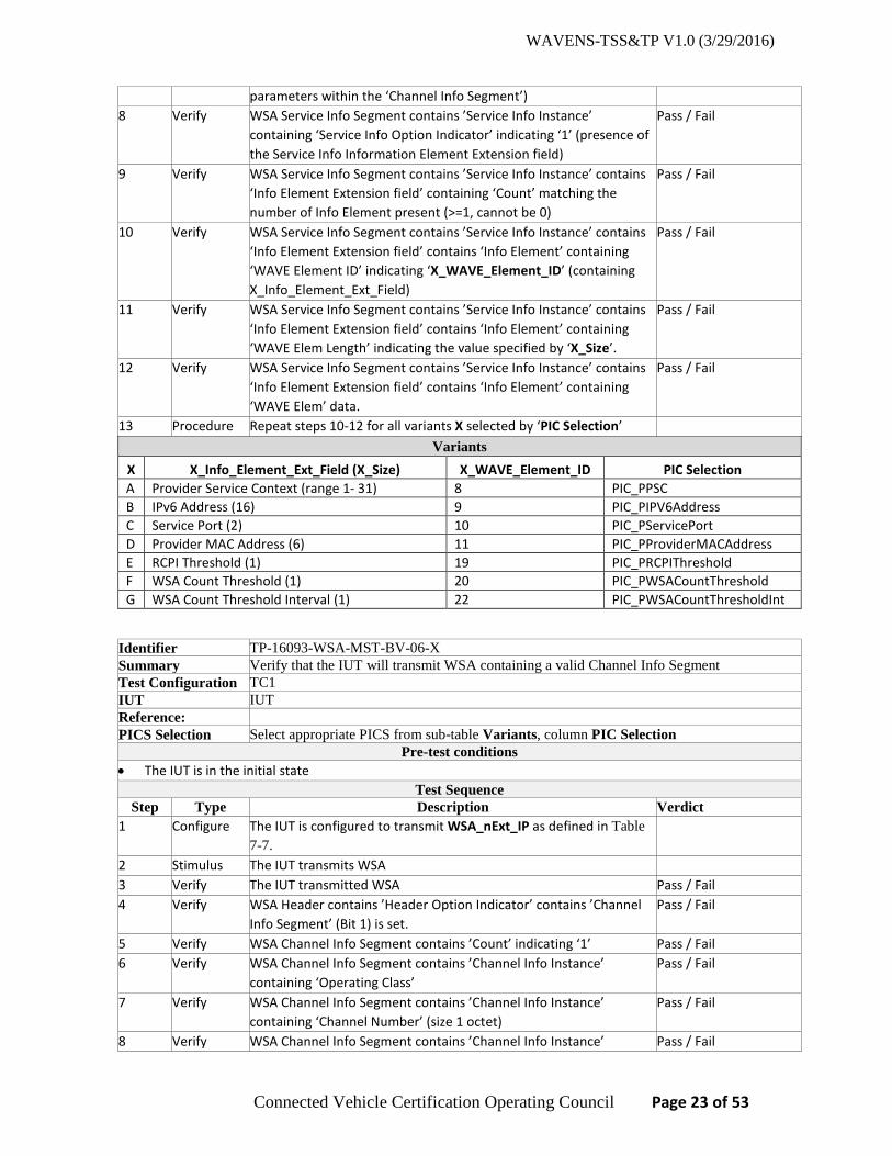
parameters within the ‘Channel Info Segment’) 8 Verify WSA Service Info Segment contains ’Service Info Instance’
containing ‘Service Info Option Indicator’ indicating ‘1’ (presence of the Service Info Information Element Extension field)
Pass / Fail
9 Verify WSA Service Info Segment contains ’Service Info Instance’ contains ‘Info Element Extension field’ containing ‘Count’ matching the number of Info Element present (>=1, cannot be 0)
Pass / Fail
10 Verify WSA Service Info Segment contains ’Service Info Instance’ contains ‘Info Element Extension field’ contains ‘Info Element’ containing ‘WAVE Element ID’ indicating ‘X_WAVE_Element_ID’ (containing X_Info_Element_Ext_Field)
Pass / Fail
11 Verify WSA Service Info Segment contains ’Service Info Instance’ contains ‘Info Element Extension field’ contains ‘Info Element’ containing ‘WAVE Elem Length’ indicating the value specified by ‘X_Size’.
Pass / Fail
12 Verify WSA Service Info Segment contains ’Service Info Instance’ contains ‘Info Element Extension field’ contains ‘Info Element’ containing ‘WAVE Elem’ data.
Pass / Fail
13 Procedure Repeat steps 10-12 for all variants X selected by ‘PIC Selection’ Variants
X X_Info_Element_Ext_Field (X_Size) X_WAVE_Element_ID PIC Selection A Provider Service Context (range 1- 31) 8 PIC_PPSC B IPv6 Address (16) 9 PIC_PIPV6Address C Service Port (2) 10 PIC_PServicePort D Provider MAC Address (6) 11 PIC_PProviderMACAddress E RCPI Threshold (1) 19 PIC_PRCPIThreshold F WSA Count Threshold (1) 20 PIC_PWSACountThreshold G WSA Count Threshold Interval (1) 22 PIC_PWSACountThresholdInt
Identifier TP-16093-WSA-MST-BV-06-X Summary Verify that the IUT will transmit WSA containing a valid Channel Info Segment Test Configuration TC1 IUT IUT Reference: PICS Selection Select appropriate PICS from sub-table Variants, column PIC Selection
Pre-test conditions • The IUT is in the initial state
Test Sequence Step Type Description Verdict
1 Configure The IUT is configured to transmit WSA_nExt_IP as defined in Table 7-7.
2 Stimulus The IUT transmits WSA 3 Verify The IUT transmitted WSA Pass / Fail 4 Verify WSA Header contains ’Header Option Indicator’ contains ’Channel
Info Segment’ (Bit 1) is set. Pass / Fail
5 Verify WSA Channel Info Segment contains ’Count’ indicating ‘1’ Pass / Fail 6 Verify WSA Channel Info Segment contains ’Channel Info Instance’
containing ‘Operating Class’ Pass / Fail
7 Verify WSA Channel Info Segment contains ’Channel Info Instance’ containing ‘Channel Number’ (size 1 octet)
Pass / Fail
8 Verify WSA Channel Info Segment contains ’Channel Info Instance’ Pass / Fail
WAVENS-TSS&TP V1.0 (3/29/2016)
Connected Vehicle Certification Operating Council Page 24 of 53
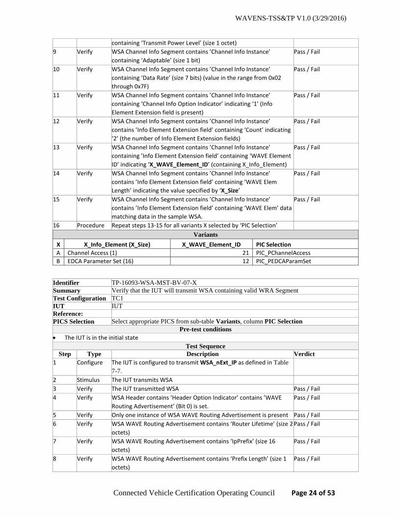
containing ‘Transmit Power Level’ (size 1 octet) 9 Verify WSA Channel Info Segment contains ’Channel Info Instance’
containing ‘Adaptable’ (size 1 bit) Pass / Fail
10 Verify WSA Channel Info Segment contains ’Channel Info Instance’ containing ‘Data Rate’ (size 7 bits) (value in the range from 0x02 through 0x7F)
Pass / Fail
11 Verify WSA Channel Info Segment contains ’Channel Info Instance’ containing ‘Channel Info Option Indicator’ indicating ‘1’ (Info Element Extension field is present)
Pass / Fail
12 Verify WSA Channel Info Segment contains ’Channel Info Instance’ contains ’Info Element Extension field’ containing ‘Count’ indicating ‘2’ (the number of Info Element Extension fields)
Pass / Fail
13 Verify WSA Channel Info Segment contains ’Channel Info Instance’ containing ’Info Element Extension field’ containing ‘WAVE Element ID’ indicating ‘X_WAVE_Element_ID’ (containing X_Info_Element)
Pass / Fail
14 Verify WSA Channel Info Segment contains ’Channel Info Instance’ contains ’Info Element Extension field’ containing ‘WAVE Elem Length’ indicating the value specified by ‘X_Size’
Pass / Fail
15 Verify WSA Channel Info Segment contains ’Channel Info Instance’ contains ’Info Element Extension field’ containing ‘WAVE Elem’ data matching data in the sample WSA.
Pass / Fail
16 Procedure Repeat steps 13-15 for all variants X selected by ‘PIC Selection’ Variants
X X_Info_Element (X_Size) X_WAVE_Element_ID PIC Selection A Channel Access (1) 21 PIC_PChannelAccess B EDCA Parameter Set (16) 12 PIC_PEDCAParamSet
Identifier TP-16093-WSA-MST-BV-07-X Summary Verify that the IUT will transmit WSA containing valid WRA Segment Test Configuration TC1 IUT IUT Reference: PICS Selection Select appropriate PICS from sub-table Variants, column PIC Selection
Pre-test conditions • The IUT is in the initial state
Test Sequence Step Type Description Verdict
1 Configure The IUT is configured to transmit WSA_nExt_IP as defined in Table 7-7.
2 Stimulus The IUT transmits WSA 3 Verify The IUT transmitted WSA Pass / Fail 4 Verify WSA Header contains ’Header Option Indicator’ contains ’WAVE
Routing Advertisement’ (Bit 0) is set. Pass / Fail
5 Verify Only one instance of WSA WAVE Routing Advertisement is present Pass / Fail 6 Verify WSA WAVE Routing Advertisement contains ‘Router Lifetime’ (size 2
octets) Pass / Fail
7 Verify WSA WAVE Routing Advertisement contains ‘IpPrefix’ (size 16 octets)
Pass / Fail
8 Verify WSA WAVE Routing Advertisement contains ‘Prefix Length’ (size 1 octets)
Pass / Fail

WAVENS-TSS&TP V1.0 (3/29/2016)
Connected Vehicle Certification Operating Council Page 25 of 53
9 Verify WSA WAVE Routing Advertisement contains ‘Default Gateway’ (size 16 octets)
Pass / Fail
10 Verify WSA WAVE Routing Advertisement contains ‘Primary DNS’ (size 16 octets)
Pass / Fail
11 Verify WSA WAVE Routing Advertisement contains ’Info Element Extension field’ containing ‘Count’ indicating the number of ‘Info Elements’
Pass / Fail
12 Verify WSA WAVE Routing Advertisement contains ’Info Element Extension field’ containing ‘WAVE Element ID’ indicating ‘X_Info_Element’
Pass / Fail
13 Verify WSA WAVE Routing Advertisement contains ’Info Element Extension field’ containing ‘WAVE Elem Length’ not exceeding ‘X_Size’
Pass / Fail
14 Verify WSA WAVE Routing Advertisement contains ’Info Element Extension field’ containing ‘WAVE Elem’ data matching data in the sample WSA.
Pass / Fail
15 Procedure Repeat steps 12-14 for all variants X selected by ‘PIC Selection’ Variants
X X_Info_Element (X_Size) X_WAVE_Element_ID PIC Selection A Secondary DNS (size 16 octets) 13 PIC_PSecondaryDNS B Gateway MAC Address (size 6 octets) 14 PIC_PGatewayMACAddress
Identifier TP-16093-WSA-MST-BV-08 Summary Verify that the IUT will transmit WSA containing valid WSA Header Info Element Extension
field 2D Location. Test Configuration TC1 IUT IUT Reference: PICS Selection PIC_P2DLocation
Pre-test conditions • The IUT is in the initial state
Test Sequence Step Type Description Verdict
1 Configure The IUT is configured to transmit WSA_nExt_1 as defined in Table 7-6, Table 7-4, and Table 7-5, using WSAheader_2D in Table 7-9.
2 Stimulus The IUT transmits WSA 3 Verify The IUT transmitted WSA Pass / Fail 4 Verify WSA Header contains ’Header Option Indicator’ indicating ’WAVE
Info Element Extension field’ (Bit 3) is set. Pass / Fail
5 Verify WSA Header contains ’WSA Header Info Elem Extension field’ containing ’Count’ matching the number of Info Elements present in the message (cannot be ‘0’)
Pass / Fail
6 Verify WSA Header contains ’WSA Header Info Elem Extension field’ containing ‘Info Element’ containing ‘WAVE Element ID’ indicating ‘5’ (containing 2D Location)
Pass / Fail
7 Verify WSA Header contains ’WSA Header Info Elem Extension field’ containing ‘WAVE Elem Length’ not exceeding ‘9 octets’
Pass / Fail
8 Verify WSA Header contains ’WSA Header Info Elem Extension field’ containing ‘WAVE Elem’ data
Pass / Fail
Note: This TP is similar to TP-16093-WSA-PP-BV-04-B except WSA Header contains 2D instead of 3D location.
WAVENS-TSS&TP V1.0 (3/29/2016)
Connected Vehicle Certification Operating Council Page 26 of 53
6.2.8 WSA reception
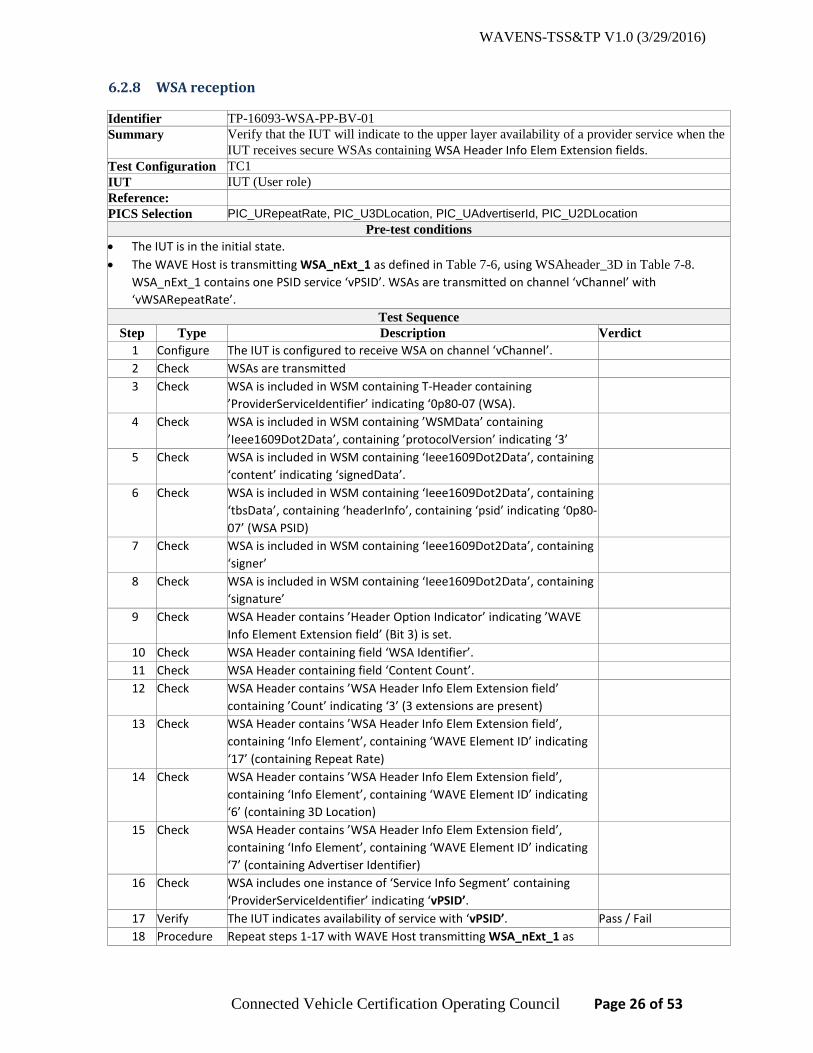
Identifier TP-16093-WSA-PP-BV-01 Summary Verify that the IUT will indicate to the upper layer availability of a provider service when the
IUT receives secure WSAs containing WSA Header Info Elem Extension fields. Test Configuration TC1 IUT IUT (User role) Reference: PICS Selection PIC_URepeatRate, PIC_U3DLocation, PIC_UAdvertiserId, PIC_U2DLocation
Pre-test conditions • The IUT is in the initial state. • The WAVE Host is transmitting WSA_nExt_1 as defined in Table 7-6, using WSAheader_3D in Table 7-8.
WSA_nExt_1 contains one PSID service ‘vPSID’. WSAs are transmitted on channel ‘vChannel’ with ‘vWSARepeatRate’.
Test Sequence Step Type Description Verdict
1 Configure The IUT is configured to receive WSA on channel ‘vChannel’. 2 Check WSAs are transmitted 3 Check WSA is included in WSM containing T-Header containing
’ProviderServiceIdentifier’ indicating ‘0p80-07 (WSA).
4 Check WSA is included in WSM containing ’WSMData’ containing ’Ieee1609Dot2Data’, containing ’protocolVersion’ indicating ‘3’
5 Check WSA is included in WSM containing ‘Ieee1609Dot2Data’, containing ‘content’ indicating ‘signedData’.
6 Check WSA is included in WSM containing ‘Ieee1609Dot2Data’, containing ‘tbsData’, containing ‘headerInfo’, containing ‘psid’ indicating ‘0p80-07’ (WSA PSID)
7 Check WSA is included in WSM containing ‘Ieee1609Dot2Data’, containing ‘signer’
8 Check WSA is included in WSM containing ‘Ieee1609Dot2Data’, containing ‘signature’
9 Check WSA Header contains ’Header Option Indicator’ indicating ’WAVE Info Element Extension field’ (Bit 3) is set.
10 Check WSA Header containing field ‘WSA Identifier’. 11 Check WSA Header containing field ‘Content Count’. 12 Check WSA Header contains ’WSA Header Info Elem Extension field’
containing ’Count’ indicating ‘3’ (3 extensions are present)
13 Check WSA Header contains ’WSA Header Info Elem Extension field’, containing ‘Info Element’, containing ‘WAVE Element ID’ indicating ‘17’ (containing Repeat Rate)
14 Check WSA Header contains ’WSA Header Info Elem Extension field’, containing ‘Info Element’, containing ‘WAVE Element ID’ indicating ‘6’ (containing 3D Location)
15 Check WSA Header contains ’WSA Header Info Elem Extension field’, containing ‘Info Element’, containing ‘WAVE Element ID’ indicating ‘7’ (containing Advertiser Identifier)
16 Check WSA includes one instance of ‘Service Info Segment’ containing ‘ProviderServiceIdentifier’ indicating ‘vPSID’.
17 Verify The IUT indicates availability of service with ‘vPSID’. Pass / Fail 18 Procedure Repeat steps 1-17 with WAVE Host transmitting WSA_nExt_1 as

WAVENS-TSS&TP V1.0 (3/29/2016)
Connected Vehicle Certification Operating Council Page 27 of 53
defined in Table 7-6, using WSAheader_2D in Table 7-9.
Identifier TP-16093-WSA-PP-BV-02 Summary Verify that the IUT will indicate to the upper layer availability of a provider service when the
IUT receives WSAs containing Service Info Segment with Info Element Extension fields. Test Configuration TC1 IUT IUT (User role) Reference:
PICS Selection PIC_UPSC, PIC_UIPV6Address, PIC_UServicePort, PIC_UProviderMACAddress, PIC_URCPIThreshold, PIC_UWSACountThreshold, PIC_UWSACountThresholdInt
Pre-test conditions • The IUT is in the initial state. • The WAVE Host transmitting WSA_nExt_IP as defined in Table 7-7. WSA_nExt_IP contains one PSID service
‘vPSID’. WSAs are transmitted on channel ‘vChannel’ with ‘vWSARepeatRate’. Test Sequence
Step Type Description Verdict 1 Configure The IUT is configured to receive WSA on channel ‘vChannel’. 2 Check WSAs are transmitted 3 Check WSA Header contains ’Header Option Indicator’ indicating ’Service
Info Segment’ (Bit 2) is set.
4 Check WSA Service Info Segment contains ’Count’ indicating ‘1’ 5 Check WSA Service Info Segment contains ’Service Info Instance’
containing ‘vPSID’
6 Check WSA Service Info Segment contains ’Service Info Instance’ containing ‘Channel Index’ indicating ‘1’ (i.e. pointer to channel parameters within the ‘Channel Info Segment’).
7 Check WSA Service Info Segment contains ’Service Info Instance’ containing ‘Service Info Option Indicator’ indicating ‘1’ (presence of the Service Info Information Element Extension field)
8 Check WSA Service Info Segment contains ’Service Info Instance’ contains ‘Info Element Extension field’ containing ‘Count’ indicating ‘7’ (7 extensions are present)
9 Check WSA Service Info Segment contains ’Service Info Instance’, containing ‘Info Element Extension field’, containing ‘Info Element’, containing ‘WAVE Element ID’ indicating ‘8’ (containing PSC)
10 Check WSA Service Info Segment contains ’Service Info Instance’, containing ‘Info Element Extension field’, containing ‘Info Element’, containing ‘WAVE Element ID’ indicating ‘9’ (containing IPv6 Address).
11 Check WSA Service Info Segment contains ’Service Info Instance’, containing ‘Info Element Extension field’, containing ‘Info Element’, containing ‘WAVE Element ID’ indicating ‘10’ (containing Service Port).
12 Check WSA Service Info Segment contains ’Service Info Instance’, containing ‘Info Element Extension field’, containing ‘Info Element’, containing ‘WAVE Element ID’ indicating ‘11’ (containing Provider MAC Address).
13 Check WSA Service Info Segment contains ’Service Info Instance’, containing ‘Info Element Extension field’, containing ‘Info Element’, containing ‘WAVE Element ID’ indicating ‘19’ (containing RCPI

WAVENS-TSS&TP V1.0 (3/29/2016)
Connected Vehicle Certification Operating Council Page 28 of 53
Threshold). 14 Check WSA Service Info Segment contains ’Service Info Instance’,
containing ‘Info Element Extension field’, containing ‘Info Element’, containing ‘WAVE Element ID’ indicating ‘20’ (containing WSA Count Threshold).
15 Check WSA Service Info Segment contains ’Service Info Instance’, containing ‘Info Element Extension field’, containing ‘Info Element’, containing ‘WAVE Element ID’ indicating ‘22’ (containing WSA Count Threshold Interval).
16 Verify The IUT indicates availability of service with ‘vPSID’. Pass / Fail
Identifier TP-16093-WSA-PP-BV-03 Summary Verify that the IUT will indicate to the upper layer availability of a provider service when the
IUT receives WSAs containing Channel Info Segment with Info Element Extension fields. Test Configuration TC1 IUT IUT (User role) Reference: PICS Selection PIC_UChannelAccess, PIC_UEDCAParamSet
Pre-test conditions • The IUT is in the initial state. • The WAVE Host transmitting WSA_nExt_IP as defined in Table 7-7. WSA_nExt_IP contains one PSID service
‘vPSID’. WSAs are transmitted on channel ‘vChannel’ with ‘vWSARepeatRate’. Test Sequence
Step Type Description Verdict 1 Configure The IUT is configured to receive WSA on channel ‘vChannel’. 2 Check WSAs are transmitted 3 Check WSA Header contains ’Header Option Indicator’ contains ’Channel
Info Segment’ (Bit 1) is set.
4 Check WSA Service Info Segment contains ’Service Info Instance’ containing ‘vPSID’
5 Check WSA Channel Info Segment contains ’Count’ indicating ‘1’ 6 Check WSA Channel Info Segment contains ’Channel Info Instance’
containing ‘Operating Class’
7 Check WSA Channel Info Segment contains ’Channel Info Instance’ containing ‘Channel Number’
8 Check WSA Channel Info Segment contains ’Channel Info Instance’ containing ‘Transmit Power Level’
9 Check WSA Channel Info Segment contains ’Channel Info Instance’ containing ‘Adaptable’
10 Check WSA Channel Info Segment contains ’Channel Info Instance’, containing ‘Data Rate’ (size 7 bits) (value in the range from 0x02 through 0x7F)
11 Check WSA Channel Info Segment contains ’Channel Info Instance’ containing ‘Channel Info Option Indicator’ indicating ‘1’ (Info Element Extension field is present)
12 Check WSA Channel Info Segment contains ’Channel Info Instance’ containing ’WAVE Info Element Extension’, containing ‘Count’ indicating ‘2’ (2 Info Element Extension fields are present)
13 Check WSA Channel Info Segment contains ’Channel Info Instance’ containing ’WAVE Info Element Extension’, containing ‘Info

WAVENS-TSS&TP V1.0 (3/29/2016)
Connected Vehicle Certification Operating Council Page 29 of 53
Element’, containing ‘WAVE Element ID’ indicating ‘21’ (containing Channel Access).
14 Check WSA Channel Info Segment contains ’Channel Info Instance’ containing ’WAVE Info Element Extension’, containing ‘Info Element’, containing ‘WAVE Element ID’ indicating ‘12’ (containing EDCA Parameter Set).
15 Verify The IUT indicates availability of service with ‘vPSID’. Pass / Fail
Identifier TP-16093-WSA-PP-BV-04 Summary Verify that the IUT will indicate to the upper layer availability of a provider service when the
IUT receives WSAs containing WAVE Router Advertisement with Info Element Extension fields.
Test Configuration TC1 IUT IUT (User role) Reference: PICS Selection PIC_USecondaryDNS, PIC_UGatewayMACAddress
Pre-test conditions • The IUT is in the initial state. • The WAVE Host transmitting WSA_nExt_IP as defined in Table 7-7. WSA_nExt_IP contains one PSID service
‘vPSID’. WSAs are transmitted on channel ‘vChannel’ with ‘vWSARepeatRate’. Test Sequence
Step Type Description Verdict 1 Configure The IUT is configured to receive WSA on channel ‘vChannel’. 2 Check WSAs are transmitted 3 Check WSA Header contains ’Header Option Indicator’ contains ’WAVE
Routing Advertisement’ (Bit 0) is set.
4 Check WSA Service Info Segment contains ’Service Info Instance’ containing ‘vPSID’
5 Check Only one instance of WSA WAVE Routing Advertisement is present 6 Check WSA WAVE Routing Advertisement contains ‘Router Lifetime’ 7 Check WSA WAVE Routing Advertisement contains ‘IpPrefix’ 8 Check WSA WAVE Routing Advertisement contains ‘Prefix Length’ 9 Check WSA WAVE Routing Advertisement contains ‘Default Gateway’ 10 Check WSA WAVE Routing Advertisement contains ‘Primary DNS’ 11 Check WSA WAVE Routing Advertisement contains ’Info Element Extension
field’ containing ‘Count’ indicating the number of ‘Info Elements’ indicating ‘2’ (2 Info Element Extension fields are present)
12 Check WSA WAVE Routing Advertisement contains ’Info Element Extension field’ containing ‘WAVE Element ID’ indicating ‘13’ (containing Secondary DNS).
13 Check WSA WAVE Routing Advertisement contains ’Info Element Extension field’ containing ‘WAVE Element ID’ indicating ‘14’ (containing Gateway MAC Address).
14 Verify The IUT indicates availability of service with ‘vPSID’. Pass / Fail
6.2.9 WSA transmission parameters
Identifier TP-16093-WSA-ROP-BV-01 Summary Verify that the IUT will transmit WSA at a specified repeat rate. Test Configuration TC1
WAVENS-TSS&TP V1.0 (3/29/2016)
Connected Vehicle Certification Operating Council Page 30 of 53
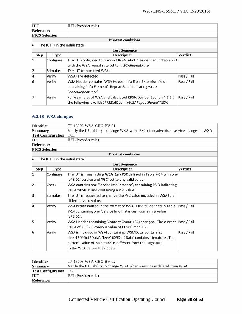
IUT IUT (Provider role) Reference: PICS Selection
Pre-test conditions • The IUT is in the initial state
Test Sequence Step Type Description Verdict
1 Configure The IUT configured to transmit WSA_nExt_1 as defined in Table 7-8, with the WSA repeat rate set to ‘vWSARepeatRate’
2 Stimulus The IUT transmitted WSAs 4 Verify WSAs are detected Pass / Fail 6 Verify WSA Header contains ’WSA Header Info Elem Extension field’
containing ‘Info Element’ ‘Repeat Rate’ indicating value ‘vWSARepeatRate’
Pass / Fail
7 Verify For n samples of WSA and calculated RRStdDev per Section 4.1.1.7, the following is valid: 2*RRStdDev < ‘vWSARepeatPeriod’*10%
Pass / Fail
6.2.10 WSA changes
Identifier TP-16093-WSA-CHG-BV-01 Summary Verify the IUT ability to change WSA when PSC of an advertised service changes in WSA. Test Configuration TC1 IUT IUT (Provider role) Reference: PICS Selection
Pre-test conditions • The IUT is in the initial state.
Test Sequence Step Type Description Verdict
1 Configure The IUT is transmitting WSA_1srvPSC defined in Table 7-14 with one ‘vPSID1’ service and ‘PSC’ set to any valid value.
2 Check WSA contains one ‘Service Info Instance’, containing PSID indicating value ‘vPSID1’ and containing a PSC value.
3 Stimulus The IUT is requested to change the PSC value included in WSA to a different valid value.
4 Verify WSA is transmitted in the format of WSA_1srvPSC defined in Table 7-14 containing one ‘Service Info Instances’, containing value ‘vPSID1’.
Pass / Fail
5 Verify WSA Header containing ‘Content Count’ (CC) changed. The current value of ‘CC’ = (‘Previous value of CC’+1) mod 16.
Pass / Fail
6 Verify WSA is included in WSM containing ’WSMData’ containing ’Ieee1609Dot2Data’. ‘Ieee1609Dot2Data’ contains ‘signature’. The current value of ‘signature’ is different from the ‘signature’ In the WSA before the update.
Pass / Fail
Identifier TP-16093-WSA-CHG-BV-02 Summary Verify the IUT ability to change WSA when a service is deleted from WSA Test Configuration TC1 IUT IUT (Provider role) Reference:
WAVENS-TSS&TP V1.0 (3/29/2016)
Connected Vehicle Certification Operating Council Page 31 of 53
PICS Selection Pre-test conditions
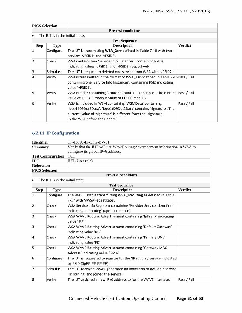
• The IUT is in the initial state. Test Sequence
Step Type Description Verdict 1 Configure The IUT is transmitting WSA_2srv defined in Table 7-16 with two
services ‘vPSID1’ and ‘vPSID2’.
2 Check WSA contains two ‘Service Info Instances’, containing PSIDs indicating values ‘vPSID1’ and ‘vPSID2’ respectively.
3 Stimulus The IUT is request to deleted one service from WSA with ‘vPSID2’. 4 Verify WSA is transmitted in the format of WSA_1srv defined in Table 7-15
containing one ‘Service Info Instances’, containing PSID indicating value ‘vPSID1’.
Pass / Fail
5 Verify WSA Header containing ‘Content Count’ (CC) changed. The current value of ‘CC’ = (‘Previous value of CC’+1) mod 16.
Pass / Fail
6 Verify WSA is included in WSM containing ’WSMData’ containing ’Ieee1609Dot2Data’. ‘Ieee1609Dot2Data’ contains ‘signature’. The current value of ‘signature’ is different from the ‘signature’ In the WSA before the update.
Pass / Fail
6.2.11 IP Configuration
Identifier TP-16093-IP-CFG-BV-01 Summary Verify that the IUT will use WaveRoutingAdvertisement information in WSA to
configure its global IPv6 address. Test Configuration TC1 IUT IUT (User role) Reference: PICS Selection
Pre-test conditions • The IUT is in the initial state
Test Sequence Step Type Description Verdict
1 Configure The WAVE Host is transmitting WSA_IProuting as defined in Table 7-17 with ‘vWSARepeatRate’.
2 Check WSA Service Info Segment containing ‘Provider Service Identifier’ indicating ‘IP routing’ (0pEF-FF-FF-FE)
3 Check WSA WAVE Routing Advertisement containing ‘IpPrefix’ indicating value ‘IPP’
3 Check WSA WAVE Routing Advertisement containing ‘Default Gateway’ indicating value ‘DG’
4 Check WSA WAVE Routing Advertisement containing ‘Primary DNS’ indicating value ‘PD’
5 Check WSA WAVE Routing Advertisement containing ‘Gateway MAC Address’ indicating value ‘GMA’
6 Configure The IUT is requested to register for the ‘IP routing’ service indicated by PSID (0pEF-FF-FF-FE)
7 Stimulus The IUT received WSAs, generated an indication of available service ‘IP routing’ and joined the service.
8 Verify The IUT assigned a new IPv6 address to for the WAVE interface. Pass / Fail
WAVENS-TSS&TP V1.0 (3/29/2016)
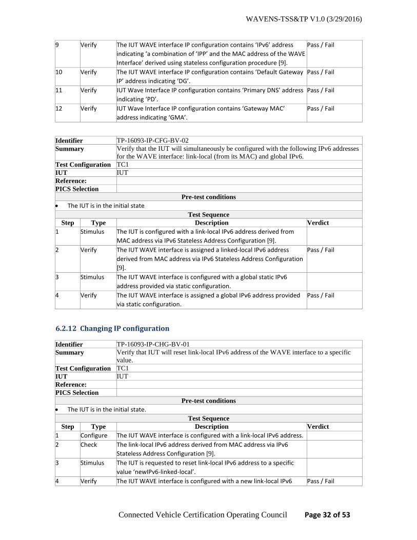
Connected Vehicle Certification Operating Council Page 32 of 53
9 Verify The IUT WAVE interface IP configuration contains ‘IPv6’ address indicating ‘a combination of ‘IPP’ and the MAC address of the WAVE Interface’ derived using stateless configuration procedure [9].
Pass / Fail
10 Verify The IUT WAVE interface IP configuration contains ‘Default Gateway IP’ address indicating ‘DG’.
Pass / Fail
11 Verify IUT Wave Interface IP configuration contains ‘Primary DNS’ address indicating ‘PD’.
Pass / Fail
12 Verify IUT Wave Interface IP configuration contains ‘Gateway MAC’ address indicating ‘GMA’.
Pass / Fail
Identifier TP-16093-IP-CFG-BV-02 Summary Verify that the IUT will simultaneously be configured with the following IPv6 addresses
for the WAVE interface: link-local (from its MAC) and global IPv6. Test Configuration TC1 IUT IUT Reference: PICS Selection
Pre-test conditions • The IUT is in the initial state
Test Sequence Step Type Description Verdict
1 Stimulus The IUT is configured with a link-local IPv6 address derived from MAC address via IPv6 Stateless Address Configuration [9].
2 Verify The IUT WAVE interface is assigned a linked-local IPv6 address derived from MAC address via IPv6 Stateless Address Configuration [9].
Pass / Fail
3 Stimulus The IUT WAVE interface is configured with a global static IPv6 address provided via static configuration.
4 Verify The IUT WAVE interface is assigned a global IPv6 address provided via static configuration.
Pass / Fail
6.2.12 Changing IP configuration
Identifier TP-16093-IP-CHG-BV-01 Summary Verify that IUT will reset link-local IPv6 address of the WAVE interface to a specific
value. Test Configuration TC1 IUT IUT Reference: PICS Selection
Pre-test conditions • The IUT is in the initial state.
Test Sequence Step Type Description Verdict
1 Configure The IUT WAVE interface is configured with a link-local IPv6 address. 2 Check The link-local IPv6 address derived from MAC address via IPv6
Stateless Address Configuration [9].
3 Stimulus The IUT is requested to reset link-local IPv6 address to a specific value ‘newIPv6-linked-local’.
4 Verify The IUT WAVE interface is configured with a new link-local IPv6 Pass / Fail

WAVENS-TSS&TP V1.0 (3/29/2016)
Connected Vehicle Certification Operating Council Page 33 of 53
address matching ‘newIPv6-link-local’.
Identifier TP-16093-IP-CHG-BV-02 Summary Verify that IUT will reset IPv6 address of the WAVE interface to a different value Test Configuration TC1 IUT IUT Reference: PICS Selection
Pre-test conditions • The IUT is in the initial state.
Test Sequence Step Type Description Verdict
1 Configure The IUT WAVE interface is configured with a link-local IPv6 address. 2 Check The link-local IPv6 address indicating value ‘IPv6-link-local’ address
derived from MAC address via IPv6 Stateless Address Configuration [9].
3 Stimulus The IUT is requested to reset link-local IPv6 address to a new undefined value.
4 Verify The IUT WAVE interface is configured with a new link-local IPv6 address different from ‘IPv6-link-local’ value.
Pass / Fail
5 Procedure Repeat steps 3-4 for 10 times and record ‘IPv6-link-local’ value for each iteration.
6 Verify ‘IPv6-link-local’ value changes to different non-repeated values Pass / Fail
6.2.13 Communication using IPv6
Identifier TP-16093-IP-COM-BV-01 Summary Verify that the IUT will initiate a 2-way communication using IPv6 protocol to a Remote
Host on a different subnet. Test Configuration TC2 IUT IUT (User role) Reference: PICS Selection
Pre-test conditions • The IUT is in the initial state.
Test Sequence Step Type Description Verdict
1 Configure The WAVE Host is transmitting WSA_IProuting defined in Table 7-17 containing ‘IP routing’ service.
2 Configure The IP Host is connected to the WAVE Host and configured with a global IPv6 address on a different subnet than the IUT’s subnet.
3 Configure The IUT received WSAs, generated an indication of the available service ‘IP routing’.
4 Check The IUT configured the WAVE interface IPv6 information using WSA’s WRA information.
5 Stimulus The IUT is sending IPv6 packets (e.g. ICMP ping6) to the IP Host global IPv6 address.
6 Verify The IUT receives responses (e.g. ICMP ping 6 echo) from the IP Host. Pass / Fail

WAVENS-TSS&TP V1.0 (3/29/2016)
Connected Vehicle Certification Operating Council Page 34 of 53
Identifier TP-16093-IP-COM-BV-02 Summary Verify that the IUT will initiate a 2-way communication using IPv6 protocol to a WAVE
Host using link-local address. Test Configuration TC2 IUT IUT (User role) Reference: PICS Selection
Pre-test conditions • The IUT is in the initial state.
Test Sequence Step Type Description Verdict
1 Configure The WAVE Host is transmitting WSA_IProuting defined in Table 7-17 containing ‘IP routing’ service.
2 Configure The IUT received WSAs, generated an indication of the available service ‘IP routing’.
3 Check The IUT configured the WAVE interface IPv6 information using WSA’s WRA information.
4 Stimulus The IUT is sending IPv6 packets (e.g. ICMP ping6) to the WAVE Host link-local IPv6 address.
5 Verify The IUT receives responses (e.g. ICMP ping 6 echo) from the WAVE Host to the IUT link-local IPv6 address.
Pass / Fail

WAVENS-TSS&TP V1.0 (3/29/2016)
Connected Vehicle Certification Operating Council Page 35 of 53
7 Messages and Information Element Contents
This section contains the default values of common messages and information elements used in TPs.
7.1 WAVE Short Messages
7.1.1 Message defaults
The following assumptions apply to all messages defined in this section.
• All WSM transmitted without IEEE 1609.2 security. • Default values for message parameters are defined in 4.1.1
7.1.2 Message details
7.1.2.1 WAVE Short Messages without optional extensions
Table 7-1 WSM_without_nExt
Information Element Value/Remark Comment WSM_without_nExt ::= SEQUENCE { controlField SEQUENCE { Subtype 0 (nullNetworking) optionIndicator 0 (not present) Version 3 } nExtensions SEQUENCE {} Not present transport bcMode (tpid = 0) PSID addressing with no WAVE
Information Element Extension field destAddress vPSID PSID values defined in Table 4-4 Body A valid WSM payload Payload is comprised of the
WSMLength and WSMData fields as specified in 8.1.3 in [2]
}
7.1.2.2 WAVE Short Messages with optional extensions
Table 7-2 WSM_nExt
Information Element Value/Remark Comment WSM_nExt ::= SEQUENCE { controlField SEQUENCE { Subtype 0 (nullNetworking) optionIndicator 1 (present) Version 3 } nExtensions SEQUENCE { { extensionId 15 (Channel Number) value Any valid value Default values defined in Table 4-1 } { extensionId 16 (Data Rate) value Any valid value Default values defined in Table 4-2 } { extensionId 4 (Tx Power Used) value Any valid value Default values defined in Table 4-3 } } transport tpid = 1 PSID addressing including WAVE
Information Element Extension field

WAVENS-TSS&TP V1.0 (3/29/2016)
Connected Vehicle Certification Operating Council Page 36 of 53
destAddress Any valid value PSID values defined in Table 4-4 body A valid WSM payload Payload is comprised of the
WSMLength and WSMData fields as specified in 8.1.3 in [2]
}
7.1.2.3 WAVE Short Messages with channel information
Table 7-3 WSM_nExt_ch
Information Element Value/Remark Comment WSM_nExt_ch ::= SEQUENCE { controlField SEQUENCE { Subtype 0 (nullNetworking) optionIndicator 1 (present) Version 3 } nExtensions SEQUENCE { { extensionId 15 (Channel Number) value Any valid value Default values defined in Table 4-1 } {} Other extensions are optional } transport bcMode (tpid = 0) PSID addressing with no WAVE
Information Element Extension field destAddress vPSID PSID values defined in Table 4-4 body A valid WSM payload Payload is comprised of the
WSMLength and WSMData fields as specified in 8.1.3 in [2]
}
7.2 WAVE Service Advertisement (WSA)
7.2.1 Message defaults
The following assumptions apply to all messages defined in this section.
• All WSA message contents are transmitted inside 1609.2 signed message data structure. • Default values for message parameters are defined in 4.1.1
7.2.2 Message details
7.2.2.1 WSM and security wrapper for WSA
Table 7-4 WSMheader_WSA
Information Element Value/Remark Comment WSMheader_WSA ::= SEQUENCE { controlField SEQUENCE { Subtype 0 (nullNetworking) optionIndicator 0 (not present) Version 3 } nExtensions SEQUENCE {} Not present transport bcMode (tpid = 0) PSID addressing with no WAVE

WAVENS-TSS&TP V1.0 (3/29/2016)
Connected Vehicle Certification Operating Council Page 37 of 53
Information Element Extension field destAddress 135 (psid=0p80-07) PSID value for WSA is 0p80-07 as
defined in [5]. body Valid WSA payload WSM payload created according to
Ieee1609Dot2Data }
Table 7-5 Ieee1609Dot2Data
Information Element Value/Remark Comment Requires WSMheader_WSA in Table 7-4
Ieee1609Dot2Data ::= SEQUENCE { protocolVersion 3 content signedData hashID sha256 tbsData SEQUENCE { payload SEQUENCE { protocolVersion 3 content unsecuredData Valid WSA payload WSA payload created according to
WSA_nExt_1, WSA_nExt_IP, or WSA_min } headerInfo SEQUENCE { psid 135 (psid=0p80-07) PSID value for WSA is 0p80-07 } } signer SEQUENCE {} Any valid value Constructed according to [8] signature SEQUENCE {} Any valid value Constructed according to [8] }
7.2.2.2 WSA with optional extension parameters
Table 7-6 WSA_nExt_1
Information Element Value/Remark Comment Requires Ieee1609Dot2Data in Table 7-5
WSA_nExt_1 ::= SEQUENCE { WSAheader SEQUENCE {} WSAheader_3D or
WSAheader_2D See definition in Table 7-8 or Table 7-9
WSAserviceInfos SEQUENCE {} WSAserviceInfos See definition in Table 7-10 WSAchannelInfos SEQUENCE {} WSAchannelInfos See definition in Table 7-12 WSAroutingAdvertisement SEQUENCE{}
Not present
}
Table 7-7 WSA_nExt_IP
Information Element Value/Remark Comment Requires Ieee1609Dot2Data in Table 7-5
WSA_nExt_IP ::= SEQUENCE { WSAheader SEQUENCE {} WSAheader_3D or
WSAheader_2D See definition in Table 7-8 or Table 7-9
WSAserviceInfos_IP SEQUENCE {} WSAserviceInfos See definition in Table 7-11 WSAchannelInfos SEQUENCE {} WSAchannelInfos See definition in Table 7-12 WSAroutingAdvertisement SEQUENCE{}
WSAroutingAdvertisement See definition in Table 7-13

WAVENS-TSS&TP V1.0 (3/29/2016)
Connected Vehicle Certification Operating Council Page 38 of 53
}
Table 7-8 WSAheader_3D
Information Element Value/Remark Comment Requires WSA_nExt_1 in Table 7-6
WSAheader_3D ::= SEQUENCE { version SEQUENCE { messageID saMessage rsvAdvPrtVersion 3 (WSA version 3) headerOptionIndicator 0b1111 } body SEQUENCE { changeCount SEQUENCE { saID Any valid value contentCount Any valid value } extensions SEQUENCE { { extensionId 17 (Repeat Rate) value Any valid value } { extensionID 6 (3D location) value SEQUENCE { latitude Any valid value longitude Any valid value elevation Any valid value } }
{ extensionID 7 (Advertiser ID) value Any valid value } } } }
Table 7-9 WSAheader_2D
Information Element Value/Remark Comment Requires WSA_nExt_1 in Table 7-6
WSAheader_3D ::= SEQUENCE { version SEQUENCE { messageID saMessage rsvAdvPrtVersion 3 (WSA version 3) headerOptionIndicator 0b1111 } body SEQUENCE { changeCount SEQUENCE { saID Any valid value contentCount Any valid value } extensions SEQUENCE { { extensionId 17 (Repeat Rate) value Any valid value } { extensionID 5 (2D location) value SEQUENCE { latitude Any valid value

WAVENS-TSS&TP V1.0 (3/29/2016)
Connected Vehicle Certification Operating Council Page 39 of 53
longitude Any valid value } }
{ extensionID 7 (Advertiser ID) value Any valid value } } } }
Table 7-10 WSAserviceInfos
Information Element Value/Remark Comment Requires WSA_nExt_1 in Table 7-6
WSAserviceInfos ::= SEQUENCE { { serviceID vPSID PSID values defined in Table 4-4 channelIndex firstEntry 1st entry in Channel Info Segment extension SEQUENCE { extensionId 8 (PSC) psc Any valid value } } }
Table 7-11 WSAserviceInfos_IP
Information Element Value/Remark Comment Requires WSA_nExt_1 in Table 7-6
WSAserviceInfos_IP ::= SEQUENCE { { serviceID vPSID PSID values defined
in 4.1.1.4 channelIndex firstEntry 1st entry in Channel
Info Segment extension SEQUENCE { { extensionId 8 (PSC) psc Any valid value } { extensionId 9 (IPv6Address) IPv6Address Any valid value } { extensionId 10 (ServicePort) ServicePort Any valid value } { extensionId 11 (ProviderMACAddress) ProviderMACAddress Any valid value } { extensionId 19 (RcpiThreshold) RcpiThreshold Any valid value } { extensionId 20 (WsaCountThreshold) WsaCountThreshold Any valid value } { extensionId 22
(WsaCountThresholdInterval)
WsaCountThresholdInterval Any valid value

WAVENS-TSS&TP V1.0 (3/29/2016)
Connected Vehicle Certification Operating Council Page 40 of 53
} } } }
Table 7-12 WSAchannelInfos
Information Element Value/Remark Comment Requires WSA_nExt_1 in Table 7-6
WSAchannelInfos ::= SEQUENCE { { operatingClass Any valid value channelNumber Any valid value powerLevel Any valid value dataRate Any valid value adaptable Any valid value extensions SEQUENCE { { extensionId 12 (EDCA) EdcaParameterSet {} Any valid value } { extensionId 21 (Channel Access) value alternatingSCH } } } }
Table 7-13 WSAroutingAdvertisement
Information Element Value/Remark Comment WSAroutingAdvertisement ::= SEQUENCE {
{ lifetime Any valid value ipPrefix Any valid value ipPrefixLength Any valid value defaultGateway Any valid value primaryDns Any valid value extensions SEQUENCE { { extensionId 14 (Gateway MAC) value Any valid value } { extensionId 13 (Secondary DNS) value Any valid value } } } }
7.2.2.3 WSA containing multiple service instances
Table 7-14 WSA_1srvPSC
Information Element Value/Remark Comment Requires Ieee1609Dot2Data in Table 7-5
WSA_1srv ::= SEQUENCE {

WAVENS-TSS&TP V1.0 (3/29/2016)
Connected Vehicle Certification Operating Council Page 41 of 53
version SEQUENCE { messageID saMessage rsvAdvPrtVersion 3 (WSA version 3) headerOptionIndicator 0b0110 } body SEQUENCE { changeCount SEQUENCE { saID Any valid value contentCount Any valid value } extensions SEQUENCE {} Not present serviceInfos SEQUENCE { serviceID vPSID PSID values defined in Table 4-4 channelIndex firstEntry 1st entry in Channel Info Segment extension SEQUENCE { extensionId 8 (PSC) psc Any valid value } } channelInfos SEQUENCE { operatingClass 17 channelNumber Any valid value Default values defined in Table 4-1 powerLevel Any valid value Default values defined in Table 4-3 dataRate Any valid value Default values defined in Table 4-2 adaptable Any valid value extensions SEQUENCE {} Not present routingAdvertisement SEQUENCE{} Not present }
Table 7-15 WSA_1srv
Information Element Value/Remark Comment Requires Ieee1609Dot2Data in Table 7-5
WSA_1srv ::= SEQUENCE { version SEQUENCE { messageID saMessage rsvAdvPrtVersion 3 (WSA version 3) headerOptionIndicator 0b0110 } body SEQUENCE { changeCount SEQUENCE { saID Any valid value contentCount Any valid value } extensions SEQUENCE {} Not present serviceInfos SEQUENCE { serviceID vPSID1 PSID values defined in Table 4-4 channelIndex firstEntry 1st entry in Channel Info Segment chOptions SEQUENCE {} Not present } channelInfos SEQUENCE { operatingClass 17 channelNumber Any valid value Default values defined in Table 4-1 powerLevel Any valid value Default values defined in Table 4-3 dataRate Any valid value Default values defined in Table 4-2 adaptable Any valid value extensions SEQUENCE {} Not present routingAdvertisement SEQUENCE{} Not present

WAVENS-TSS&TP V1.0 (3/29/2016)
Connected Vehicle Certification Operating Council Page 42 of 53
}
Table 7-16 WSA_2srv
Information Element Value/Remark Comment Requires Ieee1609Dot2Data in Table 7-5
WSA_2srv ::= SEQUENCE { version SEQUENCE { messageID saMessage rsvAdvPrtVersion 3 (WSA version 3) headerOptionIndicator 0b0110 } body SEQUENCE { changeCount SEQUENCE { saID Any valid value contentCount Any valid value } extensions SEQUENCE {} Not present serviceInfos SEQUENCE { { serviceID vPSID1 PSID values defined in Table 4-4 channelIndex firstEntry 1st entry in Channel Info Segment chOptions SEQUENCE {} Not present } { serviceID vPSID2 (different
from vPSID) PSID values defined in Table 4-4
channelIndex firstEntry 1st entry in Channel Info Segment chOptions SEQUENCE {} Not present } } channelInfos SEQUENCE { operatingClass 17 channelNumber Any valid value Default values defined in Table 4-1 powerLevel Any valid value Default values defined in Table 4-3 dataRate Any valid value Default values defined in Table 4-2 adaptable Any valid value extensions SEQUENCE {} Not present routingAdvertisement SEQUENCE{} Not present }
7.2.2.4 WSA containing IP routing service
Table 7-17 WSA_IProuting
Information Element Value/Remark Comment Requires Ieee1609Dot2Data in Table 7-5
WSA_IProuting ::= SEQUENCE { version SEQUENCE { messageID saMessage rsvAdvPrtVersion 3 (WSA version 3) headerOptionIndicator 0b0111 } body SEQUENCE {} Any valid value serviceInfos SEQUENCE { serviceID 0pEF-FF-FF-FE PSID values defined in Table 4-4 channelIndex firstEntry 1st entry in Channel Info Segment chOptions SEQUENCE {} Any valid value
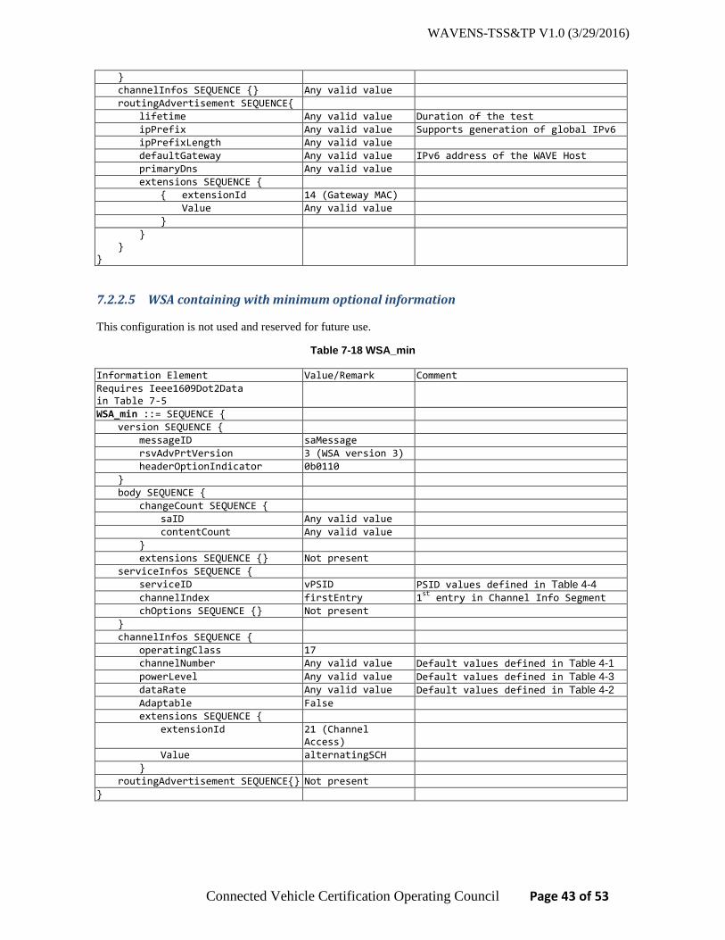
WAVENS-TSS&TP V1.0 (3/29/2016)
Connected Vehicle Certification Operating Council Page 43 of 53
} channelInfos SEQUENCE {} Any valid value routingAdvertisement SEQUENCE{ lifetime Any valid value Duration of the test ipPrefix Any valid value Supports generation of global IPv6 ipPrefixLength Any valid value defaultGateway Any valid value IPv6 address of the WAVE Host primaryDns Any valid value extensions SEQUENCE { { extensionId 14 (Gateway MAC) Value Any valid value } } } }
7.2.2.5 WSA containing with minimum optional information
This configuration is not used and reserved for future use.
Table 7-18 WSA_min
Information Element Value/Remark Comment Requires Ieee1609Dot2Data in Table 7-5
WSA_min ::= SEQUENCE { version SEQUENCE { messageID saMessage rsvAdvPrtVersion 3 (WSA version 3) headerOptionIndicator 0b0110 } body SEQUENCE { changeCount SEQUENCE { saID Any valid value contentCount Any valid value } extensions SEQUENCE {} Not present serviceInfos SEQUENCE { serviceID vPSID PSID values defined in Table 4-4 channelIndex firstEntry 1st entry in Channel Info Segment chOptions SEQUENCE {} Not present } channelInfos SEQUENCE { operatingClass 17 channelNumber Any valid value Default values defined in Table 4-1 powerLevel Any valid value Default values defined in Table 4-3 dataRate Any valid value Default values defined in Table 4-2 Adaptable False extensions SEQUENCE { extensionId 21 (Channel
Access)
Value alternatingSCH } routingAdvertisement SEQUENCE{} Not present }

WAVENS-TSS&TP V1.0 (3/29/2016)
Connected Vehicle Certification Operating Council Page 44 of 53

WAVENS-TSS&TP V1.0 (3/29/2016)
Connected Vehicle Certification Operating Council Page 45 of 53
Appendix A: Traceability Matrix
This Section shows traceability from the requirements identified by PICS from IEEE 1609.3 [2] to the Test Purposes defined in this document.
For each element in the PICS table, the Support profile is identified based on the information provided in SAE J2945/1 [1]. The following support profiles are include:
• V2V – mandatory features required for in-vehicle safety applications requiring transmission or reception of signed BSM messages.
• SCMS – Items marked SCMS are required if IPv6 communication over DSRC is supported, e.g. for communication with security service SCMS and to download security certificates from SCMS.
• RSE – mandatory feature required for roadside equipment V2V and SCMS profiles are derived from SAE J2934/1 [1]. Items left blank in the Support column are optional.
Table A- 1 IEEE 1609.3 PICS traceability to TPs
1609.3 PICS from [2]
Features in [2]
Reference section in [2]
Status (J2945-1 [1])
Support (J2945-1 [1])
TP ID TP Description
N1. DATA PLANE
N1.1. LLC 5.2 M TP-16093-WSM-MST-BV-01
To verify that the IUT will transmit a WSM with the correct version number and EtherType.
N1.1.1. LLC extensions for WSMP
7.5 N1.3:M
TP-16093-WSM-MST-BV-01
See above
N1.2. IPv6 5.3, 6.4 O1 SCMS, RSE
See TPs for N1.2.-N1.2.7.
N1.2.1. Use stateless configuration
6.4 O SCMS TP-16093-IP-CFG-BV-01
Verify that the IUT will use WaveRoutingAdvertisement information in WSA to configure its global IPv6 address.
N1.2.2. IP readdressing
6.4.2 M SCMS TP-16093-IP-CHG-BV-01
Verify that IUT will reset link-local IPv6 address of the WAVE interface to a specific value.
TP-16093-IP-CHG-BV-02
Verify that IUT will reset IPv6 address of the WAVE interface to a different value.
N1.2.3. Send IP datagrams
5.3 O2 SCMS, RSE
TP-16093-IP-COM-BV-01
Verify that the IUT will initiate a 2-way communication using IPv6 protocol to a Remote Host on a different subnet, all IP communications are carried on a Service channel.
N1.2.4. Receive IP datagrams
5.3 O2 SCMS, RSE
TP-16093-IP-COM-BV-01
See TP for N1.2.3.
N1.2.4.1. Receive by link-local address
6.4 M SCMS, RSE
TP-16093-IP-COM-BV-02
Verify that the IUT will initiate a 2-way communication using IPv6 protocol to a WAVE Host using link-local address.
N1.2.4.2. Receive by global address
6.4 M SCMS, RSE
TP-16093-IP-COM-BV-01
Verify that the IUT will initiate a 2-way communication using IPv6 protocol to a Remote Host

WAVENS-TSS&TP V1.0 (3/29/2016)
Connected Vehicle Certification Operating Council Page 46 of 53
on a different subnet, all IP communications are carried on a Service channel.
N1.2.4.3. Receive by host multicast addresses
6.4 O3 Not considered.
N1.2.4.4. Receive by router multicast addresses
6.4 O3 Not considered.
N1.2.5. UDP 5.4 O RSE TP-16093-IP-COM-BV-01
See TP for N1.2.3.
N1.2.6. TCP 5.4 O SCMS, RSE
TP-16093-IP-COM-BV-01
See TP for N1.2.3.
N1.2.7. Other IETF protocols
5.4 O Not considered
N1.3. WSMP 5.5 O1 V2V, RSE TP-16093-WSM-PP-BV-01
Verify that the IUT will receive WSM containing valid WSM-N-Header, excluding optional WAVE Info Element extensions, WSM-T-Header, and WSM Data, and matching registered PSID.
TP-16093-WSM-PP-BV-02
Verify that the IUT will receive WSM containing valid WSM-N-Header, optional WAVE Info Element extensions, WSM-T-Header, and WSM Data, and matching registered PSID.
N1.3.1. WSM reception
5.5.3 O4 V2V, RSE TP-16093-WSM-PP-BV-01 … -02
See TPs for N1.3.
TP-16093-WSM-COM-BV-02
Verify that the IUT will receive WSMs in continuous operation on a selected channel.
TP-16093-WSM-COM-BV-04
Verify that the IUT will transmit WSMs in alternating operation on a channel CH1 and receive WSMs on a channel CH2.
TP-16093-WSM-COM-BV-05
Verify that the IUT will receive WSMs in alternating operation on channels CH1 and CH2.
N1.3.1.1. Check WSMP Version number
5.5.3, 8.3.2
M V2V, RSE (Version = 3)
TP-16093-WSM-PP-BV-01 … -02
See TPs for N1.3.
N1.3.1.2. Check Subtype field
5.5.3, 8.3.2
M V2V, RSE (Subtype = 0 or 1)
TP-16093-WSM-PP-BV-01 … -02
See TPs for N1.3.
N1.3.1.3. Check TPID field
5.5.3, 8.3.2
M V2V, RSE (TPID = 0)
TP-16093-WSM-PP-
See TPs for N1.3.

WAVENS-TSS&TP V1.0 (3/29/2016)
Connected Vehicle Certification Operating Council Page 47 of 53
BV-01 … -02
N1.3.1.4. WAVE Info Elem Extension field
8.1.1 M V2V, RSE TP-16093-WSM-PP-BV-02
Verify that the IUT will receive WSM containing valid WSM-N-Header, excluding optional WAVE Info Element extensions, WSM-T-Header, and WSM Data, and matching registered PSID.
N1.3.1.5. Deliver message based on Destination Address (PSID)
5.5.3 M V2V, RSE TP-16093-WSM-PP-BV-01 … -02
See TPs for N1.3.
N1.3.2. WSM transmission
5.5.2 O4 V2V, RSE TP-16093-WSM-MST-BV-01
To verify that the IUT will transmit a WSM with the correct version number and EtherType
TP-16093-WSM-COM-BV-01
Verify that the IUT will transmit WSMs in continuous operation on a selected channel
TP-16093-WSM-COM-BV-03
Verify that the IUT will transmit WSM1 and WSM2 on channels CH1 and CH2 respectively in alternating operation.
TP-16093-WSM-COM-BV-04
Verify that the IUT will transmit WSMs in alternating operation on a channel CH1 and receive WSMs on a channel CH2.
TP-16093-WSM-POP-BI-01
Verify that the IUT will not transmit WSM with payload exceeding WsmMaxLength.
N1.3.2.1. Insert WSMP version number
8.3.2 M V2V, RSE (Version =3)
TP-16093-WSM-MST-BV-01
See above
N1.3.2.2. Insert Destination Address (PSID)
8.3.2 M V2V, RSE TP-16093-WSM-MST-BV-02
Verify that the IUT will transmit WSM containing valid WSM-T-Header, PSID and WSM Data
N1.3.2.3. Outbound message size
5.5.2 M V2V, RSE TP-16093-WSM-MST-BV-02
See above
N1.3.2.4. Transmit channel number
8.3.4.2 O RSE TP-16093-WSM-ROP-BV-01
Verify that the IUT will transmit WSM containing valid WSM-N-Header including WAVE Info Element Extension ‘Channel Number’ and matching the actual channel used by the IUT
N1.3.2.5. Transmit data rate
8.3.4.3 O RSE TP-16093-WSM-ROP-BV-02
Verify that the IUT will transmit WSM containing valid WSM-N-Header including WAVE Info Element Extension ‘Data Rate’ and matching the actual data rate used by the IUT
N1.3.2.6. Transmit Power Used
8.3.4.4 O RSE TP-16093-WSM-ROP-BV-03
Verify that the IUT will transmit WSM containing valid WSM-N-Header including WAVE Info Element Extension ‘Transmit
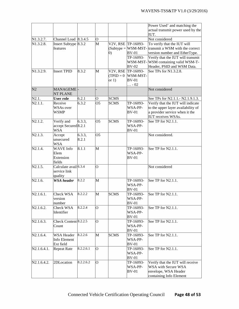
WAVENS-TSS&TP V1.0 (3/29/2016)
Connected Vehicle Certification Operating Council Page 48 of 53
Power Used’ and matching the actual transmit power used by the IUT.
N1.3.2.7. Channel Load 8.3.4.5 O Not considered N1.3.2.8. Insert Subtype
features 8.3.2 M V2V, RSE
(Subtype = 0)
TP-16093-WSM-MST-BV-01
To verify that the IUT will transmit a WSM with the correct version number and EtherType.
TP-16093-WSM-MST-BV-02
Verify that the IUT will transmit WSM containing valid WSM-T-Header, PSID and WSM Data.
N1.3.2.9. Insert TPID 8.3.2 M V2V, RSE (TPID = 0 or 1)
TP-16093-WSM-MST-BV-01 … - 02
See TPs for N1.3.2.8.
N2 MANAGEMENT PLANE
- - Not considered
N2.1. User role 6.2.1 O SCMS See TPs for N2.1.1.- N2.1.9.1.3. N2.1.1. Receive
WSAs over WSMP
6.3.2 O5 SCMS TP-16093-WSA-PP-BV-01
Verify that the IUT will indicate to the upper layer availability of a provider service when it the IUT receives WSAs.
N2.1.2. Verify and accept Secured WSA
6.3.3, 8.2.1
O5 SCMS TP-16093-WSA-PP-BV-01
See TP for N2.1.1.
N2.1.3. Accept unsecured WSA
6.3.3, 8.2.1
O5 Not considered.
N2.1.4. WAVE Info Elem Extension fields
8.1.1 M TP-16093-WSA-PP-BV-01
See TP for N2.1.1.
N2.1.5. Calculate avail service link quality
6.3.4 O Not considered
N2.1.6. WSA header 8.2.2 M TP-16093-WSA-PP-BV-01
See TP for N2.1.1.
N2.1.6.1. Check WSA version number
8.2.2.2 M SCMS TP-16093-WSA-PP-BV-01
See TP for N2.1.1.
N2.1.6.2. Check WSA Identifier
8.2.2.4 O TP-16093-WSA-PP-BV-01
See TP for N2.1.1.
N2.1.6.3. Check Content Count
8.2.2.5 O TP-16093-WSA-PP-BV-01
See TP for N2.1.1.
N2.1.6.4. WSA Header Info Element Ext field
8.2.2.6 M SCMS TP-16093-WSA-PP-BV-01
See TP for N2.1.1.
N2.1.6.4.1. Repeat Rate 8.2.2.6.1 O TP-16093-WSA-PP-BV-01
See TP for N2.1.1.
N2.1.6.4.2. 2DLocation 8.2.2.6.2 O TP-16093-WSA-PP-BV-01
Verify that the IUT will receive WSA with Secure WSA envelope, WSA Header containing Info Element

WAVENS-TSS&TP V1.0 (3/29/2016)
Connected Vehicle Certification Operating Council Page 49 of 53
Extension field 2D Location, and will indicate to the upper layer availability of a provider service included in the WSA.
N2.1.6.4.3. 3DLocation 8.2.2.6.3 O TP-16093-WSA-PP-BV-01
See TP for N2.1.1.
N2.1.6.4.4. Advertiser Identifier
8.2.2.6.4 O TP-16093-WSA-PP-BV-01
See TP for N2.1.1.
N2.1.6.4.5. Other info elements
8.2.2.6 O Not considered
N2.1.7. Service Info Segment
8.2.3 M SCMS TP-16093-WSA-PP-BV-02
Verify that the IUT will receive WSA containing Service Info Segment with Info Element Extension fields, and will indicate to the upper layer availability of a provider service included in the WSA.
N2.1.7.1. Number of Service Info Instances
8.2.3 M SCMS TP-16093-WSA-PP-BV-02
See TP for N2.1.7.
N2.1.7.2. WAVE Info Element Extension field
8.2.3.5 M SCMS TP-16093-WSA-PP-BV-02
See TP for N2.1.7.
N2.1.7.2.1. PSC 8.2.3.5.1 O SCMS TP-16093-WSA-PP-BV-02
See TP for N2.1.7.
N2.1.7.2.2. IPv6Address 8.2.3.5.2 O SCMS TP-16093-WSA-PP-BV-02
See TP for N2.1.7.
N2.1.7.2.3. Service Port 8.2.3.5.3 O SCMS TP-16093-WSA-PP-BV-02
See TP for N2.1.7.
N2.1.7.2.4. Provider MAC Address
8.2.3.5.4 O SCMS TP-16093-WSA-PP-BV-02
See TP for N2.1.7.
N2.1.7.2.5. RCPI Threshold
8.2.3.5.5 O SCMS TP-16093-WSA-PP-BV-02
See TP for N2.1.7.
N2.1.7.2.6. WSA Count Threshold
8.2.3.5.6 O SCMS TP-16093-WSA-PP-BV-02
See TP for N2.1.7.
N2.1.7.2.6.1. WSA Count Threshold Interval
8.2.3.5.7 O TP-16093-WSA-PP-BV-02
See TP for N2.1.7.
N2.1.7.2.7. Other info elements
8.2.3.5 O SCMS Not considered
N2.1.8. Channel Info Segment
8.2.4 M SCMS TP-16093-WSA-PP-BV-03
Verify that the IUT will receive WSA containing Channel Info Segment containing Info Element Extension fields, and will indicate to the upper layer availability of a provider service included in the WSA.
N.2.1.8.1. Number of 8.2.4 M SCMS TP-16093- See TP for N2.1.8.

WAVENS-TSS&TP V1.0 (3/29/2016)
Connected Vehicle Certification Operating Council Page 50 of 53
Channel Info Instances
WSA-PP-BV-03
N.2.1.8.2. WAVE Info Elem Extension field
8.2.4.8 M SCMS TP-16093-WSA-PP-BV-03
See TP for N2.1.8.
N.2.1.8.2.1. EDCA Parameter Set
8.2.4.8.1 O SCMS TP-16093-WSA-PP-BV-03
See TP for N2.1.8.
N.2.1.8.2.2. Channel Access
8.2.4.8.2 O SCMS TP-16093-WSA-PP-BV-03
See TP for N2.1.8.
N.2.1.8.2.3. Other info elements
8.2.4.8 O Not considered
N2.1.9. WAVE Router Advertisement
8.2.5.1 O SCMS TP-16093-WSA-PP-BV-04
Verify that the IUT will receive WSA containing WAVE Router Advertisement containing Info Element Extension fields, and will indicate to the upper layer availability of a provider service included in the WSA.
N2.1.9.1. WAVE Info Elem Extension field
8.2.5.7 M SCMS TP-16093-WSA-PP-BV-04
See TP for N2.1.9.
N2.1.9.1.1. Secondary DNS
8.2.5.7.1 O SCMS TP-16093-WSA-PP-BV-04
See TP for N2.1.9.
N2.1.9.1.2. Gateway MAC Address
8.2.5.7.2 O SCMS TP-16093-WSA-PP-BV-04
See TP for N2.1.9.
N2.1.9.1.3. Other info elements
8.2.5.7 O Not considered
N2.2. Provider role
6.2.1 O RSE See TPs for N2.2.- N2.2.13.1.2
N2.2.1. Send Service Advertisements over WSMP
6.2.3.3 M RSE TP-16093-WSA-MST-BV-01
Verify that the IUT will transmit a valid WSM containing WSA with valid WSM headers.
N2.2.1.1. Send secured WSA
6.2.4.2.1, 8.2.1
O6 RSE TP-16093-WSA-MST-BV-03
Verify that the IUT will transmit WSM containing a secure WSA.
N2.2.1.2. Send unsecured WSA
6.2.4.2.1, 8.2.1
O6 RSE Not considered
N2.2.2. Send repeated advertisements
6.2.4.2.1 O RSE TP-16093-WSA-ROP-BV-01
Verify that the IUT operating as provider will transmit WSA with a specific repeat rate.
N2.2.3. Change ongoing advertisements
6.2.2.2, 6.2.4.2.2
O RSE TP-16093-WSA-CHG-BV-01
Verify the IUT ability to change WSA when a new service added
N2.2.4. Delete application-service
6.2.3.6 O RSE TP-16093-WSA-CHG-BV-02
Verify the IUT ability to change WSA when a service is deleted from WSA
N2.2.5. WSA header 8.2.2 M RSE Various See TPs for N2.2.5.1-N2.2.6.5. N2.2.5.1. Set WSA
Version 8.2.2.2 M RSE TP-16093-
WSA-MST-BV-02
Verify that the IUT will transmit WSA with the correct version number and valid WSA Header.

WAVENS-TSS&TP V1.0 (3/29/2016)
Connected Vehicle Certification Operating Council Page 51 of 53
N2.2.5.2. Set WSA Identifier
8.2.2.4 M RSE TP-16093-WSA-MST-BV-02
See TP for N2.2.5.1.
N2.2.5.3. Set Content Count
8.2.2.5 M RSE TP-16093-WSA-MST-BV-02
See TP for N2.2.5.1.
N2.2.6. WSA Header Info Element Ext field
8.2.2.6 M RSE TP-16093-WSA-MST-BV-04-X
Verify that the IUT will transmit WSA containing valid WSA Header Info Element Extension fields
N2.2.6.1. Repeat Rate 8.2.2.6.1 O RSE TP-16093-WSA-MST-BV-04-A
See TP for N2.2.6.
N2.2.6.2. 2DLocation 8.2.2.6.2 O RSE TP-16093-WSA-MST-BV-08
Verify that the IUT will transmit WSA containing valid WSA Header Info Element Extension field 2D Location.
N2.2.6.3. 3DLocation 8.2.2.6.3 O RSE TP-16093-WSA-MST-BV-04-B
See TP for N2.2.6.
N2.2.6.4. AdvertiserIdentifier
8.2.2.6.4 O RSE TP-16093-WSA-MST-BV-04-C
See TP for N2.2.6.
N2.2.6.5. Other info elements
8.2.2.6 O RSE Not considered
N2.2.7. Service Info Segment
8.2.3 M RSE TP-16093-WSA-MST-BV-05-X
Verify that the IUT will transmit WSA containing a valid Service Info Segment
N2.2.8. Number of Service Info Instances
8.2.3 M RSE TP-16093-WSA-MST-BV-05-X
See TP for N2.2.7.
N2.2.9. WAVE Info Elem Extension field
8.2.3.5 O RSE TP-16093-WSA-MST-BV-05-X
See TP for N2.2.7.
N2.2.9.1. PSC 8.2.3.5.1 O RSE TP-16093-WSA-MST-BV-05-A
See TP for N2.2.7.
N2.2.9.2. IPv6Address 8.2.3.5.2 O RSE TP-16093-WSA-MST-BV-05-B
See TP for N2.2.7.
N2.2.9.3. Service Port 8.2.3.5.3 O RSE TP-16093-WSA-MST-BV-05-C
See TP for N2.2.7.
N2.2.9.4. Provider MAC Address
8.2.3.5.4 O RSE TP-16093-WSA-MST-BV-05-D
See TP for N2.2.7.
N2.2.9.5. RCPI Threshold 8.2.3.5.5 O RSE TP-16093-WSA-MST-BV-05-E
See TP for N2.2.7.
N2.2.9.6. WSA Count Threshold
8.2.3.5.6 O RSE TP-16093-WSA-MST-BV-05-F
See TP for N2.2.7.
N2.2.9.6.1. WSA Count Threshold Interval
8.2.3.5.7 O RSE TP-16093-WSA-MST-BV-05-G
See TP for N2.2.7.
N2.2.9.7. Other info elements
8.2.3.5 O RSE Not considered

WAVENS-TSS&TP V1.0 (3/29/2016)
Connected Vehicle Certification Operating Council Page 52 of 53
N2.2.10. Channel Info Segment
8.2.4 M RSE TP-16093-WSA-MST-BV-06-X
Verify that the IUT will transmit WSA containing a valid Channel Info Segment
N2.2.11. Number of Channel Info Instances
8.2.4 M RSE TP-16093-WSA-MST-BV-06-X
See TP for N2.2.10.
N2.2.12. WAVE Info Elem Extension field
8.2.4.8 O RSE TP-16093-WSA-MST-BV-06-X
See TP for N2.2.10.
N2.2.12.1. EDCA Parameter Set
8.2.4.8.1 O RSE TP-16093-WSA-MST-BV-06-B
See TP for N2.2.10.
N2.2.12.2. Channel Access 8.2.4.8.2 O RSE TP-16093-WSA-MST-BV-06-A
See TP for N2.2.10.
N2.2.12.3. Other info elements
8.2.4.8 O RSE Not considered
N2.2.13. Send WRA 8.2.5 O RSE TP-16093-WSA-MST-BV-07-X
Verify that the IUT will transmit WSA containing valid WRA Segment
N2.2.13.1. WAVE Info Elem Extension field
8.2.5.7 O RSE TP-16093-WSA-MST-BV-07-X
See TP for N2.2.13.
N2.2.13.1.1. Secondary DNS 8.2.5.7.1 O RSE TP-16093-WSA-MST-BV-07-A
See TP for N2.2.13.
N2.2.13.1.2 Gateway MAC address
8.2.5.7.2 O RSE TP-16093-WSA-MST-BV-07-B
See TP for N2.2.13.
N2.2.13.1.3. Other info elements
8.2.5.7 O Not considered
N2.3. Timing advertisement
- Not considered
N2.3.1. Timing Advertisement generation
6.2.4.3 O Not considered
N2.4. MIB maintenance
6.5 Not considered
N2.4.1. Managed WAVE device
6.5 O Not considered
N2.4.2. MIB per standard
6.5 N2.4.1:M
Not considered
N2.4.3. Other MIB 6.5 O Not considered
Revision History
V0.1.0 Sep 2015 Initial Draft
V0.2.0 Sep 17, 2015 Editorial comments

WAVENS-TSS&TP V1.0 (3/29/2016)
Connected Vehicle Certification Operating Council Page 53 of 53
V0.4.0 Nov 18, 2015 - Added message templates for WSM and WSAs. - Specified default values for WSM/WSA parameters - Removed test cases related to IPv6 multi-casting
V0.5.0 Dec 1, 2015 - Revised traceability table, updated some TPs V0.6.0 Jan 6, 2016 - Multiple changes based on peer review/comments V1.0 Mar 29, 2016 - Incorporated comments from reviewers
◙ End of Document ◙