connection technology for linear motion ... - bosch rexroth
TRANSCRIPT

1.3
Connection technologyfor Linear Motion Systems1.3
Connection technology for Linear Motion Systems

2 Connection technology for Linear Motion Systems 1.3
Bosch Rexroth AG, R310EN 2606 (2017-04)

3Connection technology for Linear Motion Systems 1.3 3
Bosch Rexroth AG, R310EN 2606 (2017-04)
The easy way to connect your linear motion systems – fast, flexible and accurate!
Minimum mounting times, maximum effi-ciency, connection kits reduce your effort significantly at the installation stage. The mechanical systems have positive-locking interfaces throughout. They can be quickly and accurately connected together without time-consuming alignment.
The result: Users can respond flexibly to different handling applications and requirements.
X Please configure linear motion systems using the product catalogs and combine them with the connection kits from this catalog.
X Connection kit dimensioning
The connection kits are designed for geometric compatibility. The connection kits need to be technically checked for load-bearing capability according to the application.
Contents
4 Combination options for X-Z linear motion systems
6 Combination options for X-Y linear motion systems
10 How to find the connection kit you need
25 Notes
27 Permissible loads of the connection kits
34 Combination options for X-Z configurations
46 Combination options for X-Y configurations
60 Combination options with profiles
70 Cable drag chains

4 Connection technology for Linear Motion Systems 1.3 | Overview of the configuration options
Bosch Rexroth AG, R310EN 2606 (2017-04)
Compact Module CKx
Compact Module CKx
x-axis z-axis
Combination options for X-Z linear motion systems
Feed Module VKK Feed Module VKK
Compact Module CKxCompact Module CKx
Feed Module VKK
Linear Module MKx
Compact Module CKxCompact Module CKxOmega Module OBB
Linear Module MKx
38
34
39
35
40
44
42 46 48

5Overview of the configuration options | Connection technology for Linear Motion Systems 1.3 5
Bosch Rexroth AG, R310EN 2606 (2017-04)
z-axis
Ball Rail Table TKKBall Rail Table TKK
58
x-axis
Feed Module VKKOmega Module OBB
43

6 Connection technology for Linear Motion Systems 1.3 | Overview of the configuration options
Bosch Rexroth AG, R310EN 2606 (2017-04)
x-axis y-axis
Combination options for X-Y linear motion systems
Compact Module CKxCompact Module CKx Compact Module CKx Compact Module CKx
Linear Module MKxCompact Module CKx (2X-Y) Linear Module MKx (2X-Y)
Ball Rail Table TKKBall Rail Table TKK
50 46 48
52 56
58

7Overview of the configuration options | Connection technology for Linear Motion Systems 1.3 7
Bosch Rexroth AG, R310EN 2606 (2017-04)

8 Connection technology for Linear Motion Systems 1.3 | Benefits
Bosch Rexroth AG, R310EN 2606 (2017-04)
Connection technology for linear motion systems – the fast and easy way to combine electromechan-ical components
c Angle bracket connection kit
c Plate connection kit
c Connection kit
The well-thought-out and standardized mechanical interface further enhances the modularity and efficiency of the linear motion system building system.The electromechanical linear motion system components fit perfectly thanks to the positive locking interface. As a result, users can put together complete systems quickly and easily to meet their own specific handling tasks. The innovative locating grid and centering ring technology ensures unrivaled precision and reproducibility when connecting various linear motion systems.In terms of design and scope, the connection element portfolio is optimally adapted to match the components and each specific connecting task, enabling a very broad spectrum of combinations and assembly options. The entire range has been designed to minimize effort every step of the way.The connection elements can also be used with further strut profile accessories to build frames and supporting structures. The linear motion system building system also includes adapters for integrating cable drag chains and guide channels.If desired, systems can also be delivered completely pre-assembled.

9Benefits | Connection technology for Linear Motion Systems 1.3 9
Bosch Rexroth AG, R310EN 2606 (2017-04)
Linear motion system – connection technology
Build powerful handling systems easily and flexibly – with connection technology from RexrothAdvantages:
X Easy and fast assembly thanks to direct connections or pre-fabricated assemblies
X Positive-locking and force-fit connections by means of centering elements
X Optimized execution and shape X Weight-optimized X Broad spectrum of combination options
Benefits:
X Reduced design and installation effort saves time and money
X High accuracy, durability, and reproducibility X Minimized space requirement and weight, yet high
stability and dynamics X Flexible thanks to component commonality

(+)
(–)(–)
(+)M
xM
z
+Fz
+Fy
–Fy
–Fz
+Fx
–Fx
(+)
(–)
My
10
Bosch Rexroth AG, R310EN 2606 (2017-04)
Connection technology for Linear Motion Systems 1.3 | How to find the connection kit you need
How to find the connection kit you need
Perfectly combined – more than just on directionDefine the linear motion system in the product catalogs and find the required connection kit for your desired combination in this catalog.
General InformationThe following examples describe how linear motion systems are connected to a linear gantry (Part I) or a 3-dimensional gantry (Part II). By combining several of these connections, complex multiaxis systems can be built with ease.
Installation position
in x-z-direction
The division into X-Y and X-Z directions in this catalog merely serves as classification criterion (e.g. for the direc-tion of force). The products can be installed in any position.
in x-y-directionx-axis y-axis
Compact Module CKxCompact Module CKx Compact Module CKx Compact Module CKx
Compact Module CKx
x-axis z-axis
Compact Module CKxCompact Module CKxOmega Module OBB
42 46 48

Short product name, length MKR-110-NN-2, ... mm
Guideway Drive
Gear ratio
Dri
ve
jour
nal
Gear unit
right/left
Gear unit
right/left
Gear unit with second journal
Carriage
Lca = 210 mm Lca = 305mm
with T-slot
with T-slot
with thread
with thread
Version
with
gea
r un
it (
MG
),
gear
red
ucer
1111
Bosch Rexroth AG, R310EN 2606 (2017-04)
How to find the connection kit you need | Connection technology for Linear Motion Systems 1.3
Selecting the linear motion axis
Combining the linear motion axes
= possible selection
At the beginning of planning a multi-axis combination, suitable individual axes are selected according to the load and application.This is done according to the product catalog of the respective linear motion system.
X Product catalog "Configuration and ordering”
X Connection technology for linear motion systems catalog
YX
Linear Module MKx – Linear Module MKx
Connection with plate 2X-Y(with clamping fixture)
Components Carriage optionx-axis MKx Carriage, with T-slot
y-axis MKx any
Scope of supplyConnection plate, anchor strips, clamping fixtures, socket head cap screws
Based on the selected individual axes (components) and the intended connection type (X-Y, X-Z, etc.), certain product features (options) may be required. These are specified here in the “Connection technology for linear motion systems” catalog with the respective connection.
The required product features (options) need to be taken into account when configuring the individual linear motion axes (components).

12
Bosch Rexroth AG, R310EN 2606 (2017-04)
Connection technology for Linear Motion Systems 1.3 | How to find the connection kit you need
YX
Linear Module MKx – Compact Module CKx
Connection via angle brackets 2X-Y linear module - carriage with T-slotFor this connection, the appropriate order options must be selected when configuring the Compact Modules and Linear Modules, see Compact Modules and Linear Modules catalogs, "Configuration and ordering” section.
Components Guideway option Carriage option
x-axis MKx any Carriage with T-sloty-axis CKx mounting-dependent any
Scope of supplyConnection bracket (material: Al), clamping fixtures (material: Al), screws, centering rings for CKx -200: Connec-tion bracket (material: Al), screws, centering rings, washers, sliding blocks
c 2X-Y connection c Angle bracket connection kit
c CKx -200 adapted with sliding blocks
Identifying the connection kitThe connection elements therefore need to be identified when selecting the product.The guideway and carriage options are pertinent as these will be connected. Depending on the characteristics of the linear motion axes, both the same options (e.g. carriage on carriage) and different options (e.g. frame on carriage) can be combined.
X Product catalog “Configuration and ordering”
X Connection technology for linear motion systems catalog
Short product name, length1) CKK-145-NN-1, ... mm
Guideway
Standard Center holes2)
with keyway
with keyway
without connection plate with connection plate
Drive Carriage
Version
With
out
atta
chm
ent
Scre
w
jour
nal Lca =
49 mmLca = 149 mm
Lca = 190 mm
Lca = variable3)
Lca = 80 mm
= selectable options

1313
Bosch Rexroth AG, R310EN 2606 (2017-04)
How to find the connection kit you need | Connection technology for Linear Motion Systems 1.3
Easily connected: the interface with centering deviceThe use of standardized centering devices makes it possible to simplify mounting and to reproduce the system mounting in the event of an exchange. For this purpose, centering rings are included in the corresponding connection groups. For the selected linear motion systems, the appropriate options must then be selected in line with the product configuration.
Depending on the linear motion system, several options are suitable for the connection and the selection is dependent on the planned mounting. This applies to connections with compact modules, for example. One of the frame options shown below can be used accordingly. Here, the design engineer has all the freedom needed to adapt the product to the intended use.The use of centering rings is optional in terms of load capacity since the technical data for the assembly are determined without them.
X Connection technology for linear motion systems catalog
X Product catalog “Guideway/carriage options”
Compact Module CKx – Compact Module CKx
Direct connection X-Y(Can also be used as an X-Z connection)For this connection, the appropriate order options must be selected when configuring the Compact Modules, see Com-pact Modules catalog, “Configuration and ordering” section.
Carriage travelsComponents Guideway option Carriage option
x-axis CKK, CKR any “41” (“09”)
y-axis CKK, CKR mounting-dependent “41” (“09”)
Frame travelsComponents Guideway option Carriage option
x-axis CKK, CKR any “41”
y-axis CKK, CKR any “41”
YX
c Frame travels
c Clamping fixture connection kit
c Carriage travels
Option 01 /standard Option 03 /with center holes Option 04 /with center holes and long hole

14
Bosch Rexroth AG, R310EN 2606 (2017-04)
Connection technology for Linear Motion Systems 1.3 | How to find the connection kit you need
X Connection technology for linear motion systems catalog
After the connection element has been selected, it needs to be checked in terms of its use using the technical data. The coordinate system of the respective version must be observed and, depending on the mounting direction, turned to the actual position in space, if necessary.
Checking the permissible loads of the connection kits
Load calculation and comparison
Specify the operating factor CB
Mx
Mx max
My
My max
Mz
Mz max
Fx
Fx max
Fy
Fy max
Fz
Fz max + + + + + ≤ CB
Specify the operating factor CB according to the following table:
Application examples Operating factor CB
low dynamics Door guides, guiding of protective enclosures 0.85
medium dynamics Mounting devices 0.65
high dynamics PCB assembly, applications with linear motor 0.50
Fx max Fy max Fz max Mx max My max Mz max
Page Part number x-axis y-axis z-axis (N) (N) (N) (Nm) (Nm) (Nm)
ZX
ZX 29 R039110251 CKx 70 CKx 70 3 300 3 300 3 500 270 150 90
R039110253 CKx 90 CKx 70 3 500 5 600 3 500 620 150 150
R039110254 CKx 90 CKx 90 2 500 5 600 2 500 460 130 180
R039110322 CKx 110 CKx 90 2 500 5 600 2 500 500 130 170
R039110257 CKx 110 CKx 110 5 600 5 600 6 100 730 400 200
R039110319 CKx 145 CKx 110 6 100 8 100 6 100 1 400 380 350
R039110259 CKx 145 CKx 145 6 100 8 100 6 100 1 500 500 420
R039110321 CKx 200 CKx 145 6 100 13 950 6 100 2 000 860 740
R039110323 CKx 200 CKx 200 6 900 13 950 6 900 3 700 1 200 940
Permitted values for connection kits

ZX
ZX
1515
Bosch Rexroth AG, R310EN 2606 (2017-04)
How to find the connection kit you need | Connection technology for Linear Motion Systems 1.3
The two CKK-145 and VKK-070 linear motion systems were selected on the basis of the application and load as per the specifications in the respective product catalogs.
Example of how to identify the right connection kit - Part ALinear gantry as an X-Z combination
X Connection technology for linear motion systems catalog
X Product catalog “configuration and ordering”
Compact Module CKx
x-axis z-axis
Compact Module CKKx-axis
Direct connection X-ZConnection kit
Feed Module VKKz-axis
Feed Module VKK Feed Module VKKFeed Module VKK
Three configuration options are available for both of the linear motion systems selected.
The following connection was selected as suitable for the example application
1 2
1
2
Step 1 – Select the system
Selected configuration option

16
Bosch Rexroth AG, R310EN 2606 (2017-04)
Connection technology for Linear Motion Systems 1.3 | How to find the connection kit you need
X Connection technology for linear motion systems catalog
The appropriate connection kit for the selected combination now needs to be identified.The coordinate system in the configuration diagram indicates which axis is meant in the table.
Step 2 – Identify the connection kit
ZX
Compact Module CKx – Feed Module VKK
Direct connection X-ZFor this connection, the appropriate order options must be selected when configuring the Compact Modules, see Com-pact Modules catalog, “Configuration and Ordering” section.
Components Carriage option
x-axis CKK, CKR "41"("09")
Scope of supplyClamping fixtures (material: Al), sliding blocks, screws, centering rings
Connection kit
Profile nominal dimension Compact Module Profile nominal dimension Feed Module Part number mx-axis x-axis z-axis z-axis (kg)
70 CKK/CKR -070 50 VKK -050 R039120238 0.18
90 CKK/CKR -090 50 VKK -050 R039120239 0.30
70 VKK -070 R039120046
110 CKK/CKR -110 50 VKK -050 R039120239
70 VKK -070 R039120046
145 CKK/CKR -145 70 VKK -070 R039120047
100 VKK -100 R039120048 0.40
= selected connection kit

1717
Bosch Rexroth AG, R310EN 2606 (2017-04)
How to find the connection kit you need | Connection technology for Linear Motion Systems 1.3
Check component z-axis / VKK-070
Check component x-axis / CKK-145
The guideway option is pertinent for the connection here. It always comes with center holes as standard.In the Connection technology catalog, there is no specification given because every standard option is suitable.
The limit conditions of the CKK “carriage” option are checked here using the Connection technology catalog. Depending on the component, more than oneoption can be selected here. Depending on the selected drive version - either carriage version “41” or “09” is absolutely necessary for the intended X-Z connection.
Part number, lengthR1462 300 00, ... mm
Version
with
BA
SA
, w
ithou
t mot
or m
ount
with
BA
SA
an
d m
otor
mou
nt
Guideway
Short product name, length1) CKK-145-NN-1, ... mm
Guideway
Standard Center holes2)
with keyway
with keyway
without connection plate with connection plate
Drive Carriage
Version
With
out
atta
chm
ent
Scre
w
jour
nal Lca =
49 mmLca = 149 mm
Lca = 190 mm
Lca = variable3)
Lca = 80 mm
X Product catalog “Configuration and ordering”
X Product catalog "Configuration and ordering”
= selectable options

18
Bosch Rexroth AG, R310EN 2606 (2017-04)
Connection technology for Linear Motion Systems 1.3 | How to find the connection kit you need
X Connection technology for linear motion systems catalog
Step 3 – Check the permissible loads of the connection kits
Fx max Fy max Fz max Mx max My max Mz max
Page Part number x-axis y-axis z-axis (N) (N) (N) (Nm) (Nm) (Nm)
ZX
29 R039120238 CKx 70 VKK 50 1 600 13 300 1 600 200 55 415
R039120239 CKx 90 VKK 50 2 800 25 600 2 800 420 95 700
R039120046 CKx 90 VKK 70 2 800 25 600 2 800 420 125 970
R039120239 CKx 110 VKK 50 2 800 25 600 2 800 490 95 700
R039120046 CKx 110 VKK 70 2 800 25 600 2 800 490 125 970
R039120047 CKx 145 VKK 70 4 000 32 700 4 000 1 000 200 1 400
R039120048 CKx 145 VKK 100 4 000 32 700 4 000 1 000 250 1 900
Load calculation and comparison
Specify the operating factor CBSpecify the operating factor CB according to the following table:
Application examples Operating factor CB
low dynamics Door guides, guiding of protective enclosures 0.85
medium dynamics Mounting devices 0.65
high dynamics Printed circuit board assembly 0.50
Permitted values for connection kits
Mx
Mx max
My
My max
Mz
Mz max
Fx
Fx max
Fy
Fy max
Fz
Fz max + + + + + ≤ CB
= required connection kit

1919
Bosch Rexroth AG, R310EN 2606 (2017-04)
How to find the connection kit you need | Connection technology for Linear Motion Systems 1.3
The following linear motion systems were selected on the basis of the application and load as per the specifications in the respective product catalogs: 2x CKK-145 and VKK-070.
Example II – How to identify the right connection kit3-dimensional gantry as a X-Y-Z combination
X Product catalog “Configuration and ordering”
1 32
Step 1 – Select the system
Feed Module VKK1)z-axis
via angle bracketConnection kit
Direct connection1)
Compact Module CKK1)
Connection kit
y-axis
Compact Module CKKx-axis
The following connection was selected from the available assemblies.
2
1
3Z
XY
ZXY
ZXY
1) These components were already selected/checked in Part A

20
Bosch Rexroth AG, R310EN 2606 (2017-04)
Connection technology for Linear Motion Systems 1.3 | How to find the connection kit you need
YX
Connection kit
Profile nominal dimension Compact Module Profile nominal dimension Compact Module Bracket orientation Part numberx-axis x-axis y-axis y-axis
70 CKK/CKR -070 70 CKK/CKR -070 Right-hand R039110280
90 CKK/CKR -090 70 CKK/CKR -070 Right-hand R039110278
90 CKK/CKR -090 Right-hand R039110174
110 CKK/CKR -110 90 CKK/CKR -090 Right-hand R039110174
110 CKK/CKR -110 Right-hand R039110175
145 CKK/CKR -145 110 CKK/CKR -110 Right-hand R039110176145 CKK/CKR -145 Right-hand R039110177
Compact Module CKx – Compact Module CKx
Connection via bracket X-Y (reinforced right-hand version) For this connection, the appropriate order options must be selected when configuring the Compact Modules, see Com-pact Modules catalog, “Configuration and Ordering” section.
Components Guideway option Carriage option
x-axis CKK, CKR any “41” (“09”)
y-axis CKK, CKR mounting-dependent any
Scope of supplyConnection bracket (material: Al), clamping fixtures (material: Al), sliding blocks, screws, centering rings
X Connection technology for linear motion systems catalog
The appropriate connection kits for the selected combinations now need to be identified.The coordinate system in the configuration diagram indicates which axes are meant in the table.The two components to be connected must always be considered separately.
Step 2 – Identify and check the connection kit
Selecting and checking the connection kitCKK-145 with CKK-145
In the connection element catalog, the specification for the guideway option is “mounting-dependent”.Basically, each of the available standard options for the CKK can be used. However, to use the centering devices, option “03” or “04” need to be selected. Here it depends on the application as to which version is appropriate for the planned combination.
= selected connection kit

2121
Bosch Rexroth AG, R310EN 2606 (2017-04)
How to find the connection kit you need | Connection technology for Linear Motion Systems 1.3
X Product catalog Connection technology for linear motion systems
Option 01 /standard Option 03 /with center holes Option 04 /with center holes and long hole
Short product name, length1) CKK-145-NN-1, ... mm
Guideway
Standard Center holes2)
with keyway
with keyway
without connection plate with connection plate
Drive Carriage
Version
With
out
atta
chm
ent
Scre
w
jour
nal Lca =
49 mmLca = 149 mm
Lca = 190 mm
Lca = variable3)
Lca = 80 mm
X Product catalog “Configuration and ordering”
= selectable options

22
Bosch Rexroth AG, R310EN 2606 (2017-04)
Connection technology for Linear Motion Systems 1.3 | How to find the connection kit you need
To conclude, the permissible load for the second connection assembly then needs to be checked
Selecting and checking the connection kit CKK-145 with VKK-070
X Connection technology for linear motion systems catalog
ZX
Compact Module CKx – Feed Module VKK
Direct connection X-ZFor this connection, the appropriate order options must be selected when configuring the Compact Modules, see Compact Modules catalog, “Configuration and Ordering” section.
Components Carriage option
x-axis CKK, CKR “41”(“09”)
Scope of supplyClamping fixtures (material: Al), sliding blocks, screws, centering rings
Connection kit
Profile nominal dimension Compact Module Profile nominal dimension Feed Module Part number mx-axis x-axis z-axis z-axis (kg)
70 CKK/CKR -070 50 VKK -050 R039120238 0.18
90 CKK/CKR -090 50 VKK -050 R039120239 0.30
70 VKK -070 R039120046
110 CKK/CKR -110 50 VKK -050 R039120239
70 VKK -070 R039120046
145 CKK/CKR -145 70 VKK -070 R039120047
100 VKK -100 R039120048 0.40
= selected connection kit
Only the version of the carriage option for the CKK-145 axis needs to be observed here: Depending on the selected drive version - either carriage version “41” or “09” is absolutely necessary for the intended connection.

2323
Bosch Rexroth AG, R310EN 2606 (2017-04)
How to find the connection kit you need | Connection technology for Linear Motion Systems 1.3
X Product catalog “Configuration and ordering”
Short product name, length1) CKK-145-NN-1, ... mm
Guideway
Standard Center holes2)
with keyway
with keyway
without connection plate with connection plate
Drive Carriage
Version
With
out
atta
chm
ent
Scre
w
jour
nal Lca =
49 mmLca = 149 mm
Lca = 190 mm
Lca = variable3)
Lca = 80 mm
Permitted values for connection kits
Fx max Fy max Fz max Mx max My max Mz max
Page Part number x-axis y-axis z-axis (N) (N) (N) (Nm) (Nm) (Nm)
YX
32R039110280 CKx 70 CKx 70 3 300 3 300 5 600 270 720 110
R039110278 CKx 90 CKx 70 5 600 5 600 5 600 250 1 100 180
R039110174 CKx 90 CKx 90 5 600 5 600 3 300 180 1 350 210
R039110174 CKx 110 CKx 90 5 600 5 600 3 300 180 1 350 210
R039110175 CKx 110 CKx 110 5 600 5 600 5 600 370 1 500 225
R039110176 CKx 145 CKx 110 8 100 8 100 8 100 625 2 500 410
R039110177 CKx 145 CKx 145 8 100 8 100 8 100 705 2 500 410
Step 3 – Check the permissible loads of the connection kits
= selectable options
With regard to the z-axis (VKK-070), no restrictions are made because all versions are permitted.
Load calculation and comparison
Specify the operating factor CBSpecify the operating factor CB according to the following table:
Application examples Operating factor CB
low dynamics Door guides, guiding of protective enclosures 0.85
medium dynamics Mounting devices 0.65
high dynamics Printed circuit board assembly 0.50
Mx
Mx max
My
My max
Mz
Mz max
Fx
Fx max
Fy
Fy max
Fz
Fz max + + + + + ≤ CB
= required connection kit

24
Bosch Rexroth AG, R310EN 2606 (2017-04)
Connection technology for Linear Motion Systems 1.3 | How to find the connection kit you need
CKK-145 with VKK-070 X Connection technology for linear motion systems catalog
Fx max Fy max Fz max Mx max My max Mz max
Page Part number x-axis y-axis z-axis (N) (N) (N) (Nm) (Nm) (Nm)
ZX
29 R039120238 CKx 70 VKK 50 1 600 13 300 1 600 200 55 415
R039120239 CKx 90 VKK 50 2 800 25 600 2 800 420 95 700
R039120046 CKx 90 VKK 70 2 800 25 600 2 800 420 125 970
R039120239 CKx 110 VKK 50 2 800 25 600 2 800 490 95 700
R039120046 CKx 110 VKK 70 2 800 25 600 2 800 490 125 970
R039120047 CKx 145 VKK 70 4 000 32 700 4 000 1 000 200 1 400
R039120048 CKx 145 VKK 100 4 000 32 700 4 000 1 000 250 1 900
Load calculation and comparison
Specify the operating factor CBSpecify the operating factor CB according to the following table:
Application examples Operating factor CB
low dynamics Door guides, guiding of protective enclosures 0.85
medium dynamics Mounting devices 0.65
high dynamics Printed circuit board assembly 0.50
Permitted values for connection kits
Mx
Mx max
My
My max
Mz
Mz max
Fx
Fx max
Fy
Fy max
Fz
Fz max + + + + + ≤ CB
= required connection kit

2525
Bosch Rexroth AG, R310EN 2606 (2017-04)
Notes | Connection technology for Linear Motion Systems 1.3
Intended Use
X Linear motion systems and the connection technology for linear motion systems are intended for positioning in space under external loads.
X The product is intended for professional use and not for private use. X Intended use includes having read and understood this documentation, the instructions for the product, the “Safety instructions
for linear motion systems” document, and especially the section “Safety instructions”. X The product is exclusively intended for incorporation into a final machine or system or for assembling with other components
to build a final machine or system.
Misuse
Use of the product in any other way than as described under “Intended Use” is considered to be misuse and is therefore not permitted. If unsuitable products are installed or used in safety-critical applications, this may lead to uncontrolled operating statuses in the application which can cause personal injury and/or damage to property. The product may only be used in safety-critical applications if this use has been expressly specified and permitted in the product documentation.Bosch Rexroth AG will not accept any liability for injury or damage caused by misuse of the product. The risks associated with any misuse of the product shall be borne by the user aloneMisuse of the product includes:
X the transport of persons
General Safety Instructions
X The safety rules and regulations of the country in which the product is used must be complied with. X All current and applicable accident prevention and environmental regulations must be adhered to. X The product may only be used when it is in technically perfect condition. X The technical data and environmental conditions stated in the product documentation must be complied with. X The product must not be put into service until it has been verified that the final product (for example a machine or system)
into which the product has been installed complies with the country-specific requirements, safety regulations and standards for the application.
X The product is never allowed to be disassembled. Excluded from this are the activities described in the product instructions. X All notices on the product itself must be complied with. X Only use accessories and spare parts approved by the manufacturer. X The special safety requirements for specific sectors (e.g. crane construction, theaters, food technology) set forth in laws,
directives and standards must be complied with. This also includes, for example, falling loads that pose a potential hazard for people.
X The following standards must be complied with: DIN 637, ISO 3408 and DIN 69051
Notes

26
Bosch Rexroth AG, R310EN 2606 (2017-04)
Connection technology for Linear Motion Systems 1.3 | Notes
Directives and Standards
Rexroth linear motion systems are suitable for use in various applications and industries. The various industries must comply with a series of standards and guidelines.These requirements can vary significantly worldwide. It is therefore essential to understand the legislation and standards that apply in each particular region.
EN ISO 12100This standard describes the safety of machinery – general principles for design, risk assessment and risk reduction. It gives a general overview and contains a guide to the major developments governing machines and their intended use.
Directive 2006/42/ECThe European Machinery Directive describes the basic safety and health requirements for the design and manufacture of machinery. The manufacturer of a machine or his authorized representative has a duty to ensure that a risk assessment has been performed in order to determine the health and safety requirements which have to be fulfilled for that machine. The machine must be designed and built taking into account the results of the risk assessment.
Directive 2001/95/ECThis directive covers general safety requirements for any product placed on the market and intended for consumers, or likely to be used by consumers under reasonably foreseeable conditions, including products that are made available to consumers in the context of service provision for use by them
Directive 85/374/EECThis directive concerns the liability for defective products and applies to industrially manufactured movable objects, irrespective of whether or not they have been incorporated into another movable or immovable object.
Directive 76/769/EECThis directive describes the restrictions on the marketing and use of certain dangerous substances and preparations. “Substances” means chemical elements and their compounds as they occur in the natural state or as produced by industry. “Preparations” means mixtures or solutions composed of two or more substances.

(+)
(–)(–)
(+)M
xM
z
+Fz
+Fy
–Fy
–Fz
+Fx
–Fx
(+)
(–)
My
2727
Bosch Rexroth AG, R310EN 2606 (2017-04)
Permissible loads of the connection kits | Connection technology for Linear Motion Systems 1.3
Permissible loads of the connection kits
The permissible loads of the individual axes must not be exceeded. This must be checked before selecting the connec-tion kits. In some attachment variations, the permissible loads for the individual axis represent the upper load capabil-ity limits. Such connection kits are not listed in the following tables.
The permissible load values of the connection elements serve as guideline values. In the case of critical applications or applications with high dynamic loads (> 50% of the permissible loads), the connection kits must be recalculated according to the application requirements. For the external loads of a linear motion axis and the connection kits, not only the process forces but the inertial forces of the products used must always be determined and taken into consideration.

28
Bosch Rexroth AG, R310EN 2606 (2017-04)
Connection technology for Linear Motion Systems 1.3 | Permissible loads of the connection kits
Load calculation and comparison
Specify the operating factor CBSpecify the operating factor CB according to the following table:
Application examples Operating factor CB
low dynamics Door guides, guiding of protective enclosures 0.85
medium dynamics Mounting devices 0.65
high dynamics PCB assembly, applications with linear motor 0.50
Define the coordinate systemThe origin of the coordinate system for the calculation of the applied forces and moments lies at the center of the connection element, on the clamping surface of the moved linear axis.
Define the forces and load momentsAll external forces and load moments must be referred to the origin of the coordinate system.These values must be specified by the customer.
Basic principlesThe permitted values shown in the tables apply under the following conditions:
X Screws have been tightened using a torque wrench as specified in the table below X Mounting screws of strength class 8.8 have been used (are included) X Screws have been lightly lubricated X Friction coefficient µ = 0.125 X Screw connections have been calculated in accordance with VDI guideline 2230
Tightening torques
Screw thread M2 M2.5 M3 M4 M5 M6 M8 M10 M12
Tightening torque (Nm) 0.4 0.7 1.3 2.7 5.5 9.5 23 46 80
µ: 0.125; strength class: 8.8
Mx
Mx max
My
My max
Mz
Mz max
Fx
Fx max
Fy
Fy max
Fz
Fz max + + + + + ≤ CB
All screws that are not coated with a threadlocking adhesive on delivery must be secured against loosening with a suitable threadlocking adhesive (e.g. Loctite 242).

2929
Bosch Rexroth AG, R310EN 2606 (2017-04)
Permissible loads of the connection kits | Connection technology for Linear Motion Systems 1.3
Fx max Fy max Fz max Mx max My max Mz max
Page Part number x-axis y-axis z-axis (N) (N) (N) (Nm) (Nm) (Nm)
ZX
ZX 34 R039120227 CKx 90 CKx 70 2 500 20 000 2 500 750 110 440
R039120198 CKx 110 CKx 90 3 300 26 000 3 300 650 180 750
R039120199 CKx 145 CKx 110 6 100 49 000 6 100 2 100 400 1 000
ZX
ZX 35 R039110251 CKx 70 CKx 70 3 300 3 300 3 500 270 150 90
R039110253 CKx 90 CKx 70 3 500 5 600 3 500 620 150 150
R039110254 CKx 90 CKx 90 2 500 5 600 2 500 460 130 180
R039110322 CKx 110 CKx 90 2 500 5 600 2 500 500 130 170
R039110257 CKx 110 CKx 110 5 600 5 600 6 100 730 400 200
R039110319 CKx 145 CKx 110 6 100 8 100 6 100 1 400 380 350
R039110259 CKx 145 CKx 145 6 100 8 100 6 100 1 500 500 420
R039110321 CKx 200 CKx 145 6 100 13 950 6 100 2 000 860 740
R039110323 CKx 200 CKx 200 6 900 13 950 6 900 3 700 1 200 940
ZX
38 R039120238 CKx 70 VKK 50 1 600 13 300 1 600 200 55 415
R039120239 CKx 90 VKK 50 2 800 25 600 2 800 420 95 700
R039120046 CKx 90 VKK 70 2 800 25 600 2 800 420 125 970
R039120239 CKx 110 VKK 50 2 800 25 600 2 800 490 95 700
R039120046 CKx 110 VKK 70 2 800 25 600 2 800 490 125 970
R039120047 CKx 145 VKK 70 4 000 32 700 4 000 1 000 200 1 400
R039120048 CKx 145 VKK 100 4 000 32 700 4 000 1 000 250 1 900
ZX
39 R039120228 CKx 70 VKK 50 390 3 100 55 600 3 300 2 500 440
R039120227 CKx 90 VKK 50 830 6 600 21 800 670 670 110
R039120206 CKx 90 VKK 70 830 6 600 21 800 670 670 110
R039120207 CKx 110 VKK 70 1 400 11 300 21 800 520 550 85
R039120208 CKx 110 VKK 100 1 400 11 300 55 600 3 300 1 900 445
R039120209 CKx 145 VKK 100 2 000 16 300 32 700 3 100 1 400 445
ZX
40 R039110251 CKx 70 VKK 50 2 200 2 200 3 500 280 310 90
R039110253 CKx 90 VKK 50 2 300 3 700 3 500 620 310 150
R039110317 CKx 90 VKK 70 1 600 3 700 2 500 465 110 180
R039110316 CKx 110 VKK 50 2 800 3 700 4 200 700 185 170
R039110318 CKx 110 VKK 70 2 800 3 700 4 200 740 190 170
R039110319 CKx 145 VKK 70 4 000 5 400 6 100 1 400 900 355
R039110320 CKx 145 VKK 100 4 000 5 400 6 100 1 400 650 355
R039110321 CKx 200 VKK 100 4 000 9 200 6 100 2 000 600 740
ZX
42 R039110298 CKx 90 OBB -055 5 600 6 100 5 600 190 165 980
R039110298 CKx 110 OBB -055 5 600 6 100 5 600 190 165 980
R039110300 CKx 145 OBB -055 6 100 6 100 6 100 190 240 980
R039110301 CKx 145 OBB -085 8 100 8 100 8 100 355 380 1 300
R039110302 CKx 200 OBB -120 8 100 13 900 8 100 785 535 4 400
Permitted values for connection kits

30
Bosch Rexroth AG, R310EN 2606 (2017-04)
Connection technology for Linear Motion Systems 1.3 | Permissible loads of the connection kits
Fx max Fy max Fz max Mx max My max Mz max
Page Part number x-axis y-axis z-axis (N) (N) (N) (Nm) (Nm) (Nm)
ZX
44 R039110060 MKx 80 MKx 65 2 100 2 100 4 000 500 360 70
R039110060 MKx 80 MKx 80 2 100 2 100 4 000 500 380 70
R039110055 MKx 110 MKx 80 3 000 3 000 4 000 1 000 380 150
R039110053 MKx 110 MKx 110 3 000 3 000 6 100 1 000 400 150
R039110052 MKx 145 MKx 110 5 200 5 200 6 100 2 400 400 330
R039110052 MKx 165 MKx 110 5 200 5 200 6 100 2 500 400 370
R039110050 MKx 165 MKx 165 5 200 5 200 8 700 2 500 420 370
ZXY Y
Z XX
45 R039110058 MKx 80 MKx 65 4 200 2 100 2 100 60 220 390
R039110059 MKx 80 MKx 80 4 200 2 100 2 100 70 220 390
R039110054 MKx 110 MKx 80 4 200 3 000 3 000 100 280 730
R039110053 MKx 110 MKx 110 6 100 2 100 5 200 200 410 1 400
R039110052 MKx 145 MKx 110 6 100 5 200 5 200 330 740 2 400
R039110052 MKx 165 MKx 110 5 100 5 200 2 100 330 250 2 400
R039110050 MKx 165 MKx 165 8 700 5 200 5 200 370 420 2 500
ZXY Y
Z XX
43 R039110283 OBB -055 VKK 50 45 000 6 400 6 400 255 1 400 1 400
R039110284 OBB -085 VKK 70 45 000 6 400 6 400 310 1 900 1 900
R039110285 OBB -120 VKK 100 65 400 9 300 9 300 560 560 3 800
YX
YX
46 R039120238 CKx 70 CKx 70 1 600 1 600 13 300 200 560 73
R039120239 CKx 90 CKx 70 2 800 2 800 22 600 420 960 125
R039120045 CKx 90 CKx 90 1 600 1 600 13 300 250 670 87
R039120239 CKx 110 CKx 70 1 600 1 600 13 300 290 560 74
R039120045 CKx 110 CKx 90 1 600 1 600 13 300 290 670 87
R039120046 CKx 110 CKx 110 2 800 2 800 22 600 490 1 400 180
R039120242 CKx 145 CKx 90 1 600 1 600 13 300 400 670 90
R039120047 CKx 145 CKx 110 4 000 4 000 32 700 1 000 2 000 270
R039120048 CKx 145 CKx 145 4 000 4 000 32 700 1 000 2 600 335
R039120049 CKx 200 CKx 145 4 000 4 000 32 700 1 330 2 600 345
R039120145 CKx 200 CKx 200 6 900 6 900 55 600 2 200 6 100 790
YX
YX
48 R039110252 CKx 70 CKx 70 3 300 3 300 3 500 150 720 110
R039110324 CKx 90 CKx 70 5 600 3 500 3 500 140 1 000 210
R039110255 CKx 90 CKx 90 5 600 4 200 4 200 220 1 400 210
R039110255 CKx 110 CKx 90 5 600 4 200 4 200 220 1 400 210
R039110325 CKx 90 CKx 110 5 600 4 200 4 200 270 1 400 210
R039110256 CKx 110 CKx 110 5 600 5 600 6 100 400 1 500 220
R039110326 CKx 145 CKx 110 8 100 6 100 6 100 400 2 400 410
R039110327 CKx 110 CKx 145 5 600 4 200 4 200 410 1 700 250
R039110258 CKx 145 CKx 145 8 100 6 100 6 100 500 2 400 410
R039110328 CKx 200 CKx 145 13 900 6 100 6 100 500 3 900 1 000
R039110329 CKx 200 CKx 200 13 900 6 900 6 900 610 4 100 1 000

3131
Bosch Rexroth AG, R310EN 2606 (2017-04)
Permissible loads of the connection kits | Connection technology for Linear Motion Systems 1.3
Fx max Fy max Fz max Mx max My max Mz max
Page Part number x-axis y-axis z-axis (N) (N) (N) (Nm) (Nm) (Nm)
ZX
44 R039110060 MKx 80 MKx 65 2 100 2 100 4 000 500 360 70
R039110060 MKx 80 MKx 80 2 100 2 100 4 000 500 380 70
R039110055 MKx 110 MKx 80 3 000 3 000 4 000 1 000 380 150
R039110053 MKx 110 MKx 110 3 000 3 000 6 100 1 000 400 150
R039110052 MKx 145 MKx 110 5 200 5 200 6 100 2 400 400 330
R039110052 MKx 165 MKx 110 5 200 5 200 6 100 2 500 400 370
R039110050 MKx 165 MKx 165 5 200 5 200 8 700 2 500 420 370
ZXY Y
Z XX
45 R039110058 MKx 80 MKx 65 4 200 2 100 2 100 60 220 390
R039110059 MKx 80 MKx 80 4 200 2 100 2 100 70 220 390
R039110054 MKx 110 MKx 80 4 200 3 000 3 000 100 280 730
R039110053 MKx 110 MKx 110 6 100 2 100 5 200 200 410 1 400
R039110052 MKx 145 MKx 110 6 100 5 200 5 200 330 740 2 400
R039110052 MKx 165 MKx 110 5 100 5 200 2 100 330 250 2 400
R039110050 MKx 165 MKx 165 8 700 5 200 5 200 370 420 2 500
ZXY Y
Z XX
43 R039110283 OBB -055 VKK 50 45 000 6 400 6 400 255 1 400 1 400
R039110284 OBB -085 VKK 70 45 000 6 400 6 400 310 1 900 1 900
R039110285 OBB -120 VKK 100 65 400 9 300 9 300 560 560 3 800
YX
YX
46 R039120238 CKx 70 CKx 70 1 600 1 600 13 300 200 560 73
R039120239 CKx 90 CKx 70 2 800 2 800 22 600 420 960 125
R039120045 CKx 90 CKx 90 1 600 1 600 13 300 250 670 87
R039120239 CKx 110 CKx 70 1 600 1 600 13 300 290 560 74
R039120045 CKx 110 CKx 90 1 600 1 600 13 300 290 670 87
R039120046 CKx 110 CKx 110 2 800 2 800 22 600 490 1 400 180
R039120242 CKx 145 CKx 90 1 600 1 600 13 300 400 670 90
R039120047 CKx 145 CKx 110 4 000 4 000 32 700 1 000 2 000 270
R039120048 CKx 145 CKx 145 4 000 4 000 32 700 1 000 2 600 335
R039120049 CKx 200 CKx 145 4 000 4 000 32 700 1 330 2 600 345
R039120145 CKx 200 CKx 200 6 900 6 900 55 600 2 200 6 100 790
YX
YX
48 R039110252 CKx 70 CKx 70 3 300 3 300 3 500 150 720 110
R039110324 CKx 90 CKx 70 5 600 3 500 3 500 140 1 000 210
R039110255 CKx 90 CKx 90 5 600 4 200 4 200 220 1 400 210
R039110255 CKx 110 CKx 90 5 600 4 200 4 200 220 1 400 210
R039110325 CKx 90 CKx 110 5 600 4 200 4 200 270 1 400 210
R039110256 CKx 110 CKx 110 5 600 5 600 6 100 400 1 500 220
R039110326 CKx 145 CKx 110 8 100 6 100 6 100 400 2 400 410
R039110327 CKx 110 CKx 145 5 600 4 200 4 200 410 1 700 250
R039110258 CKx 145 CKx 145 8 100 6 100 6 100 500 2 400 410
R039110328 CKx 200 CKx 145 13 900 6 100 6 100 500 3 900 1 000
R039110329 CKx 200 CKx 200 13 900 6 900 6 900 610 4 100 1 000
1) Carriage with threads 2) Carriage with T-slots

32
Bosch Rexroth AG, R310EN 2606 (2017-04)
Connection technology for Linear Motion Systems 1.3 | Permissible loads of the connection kits
Fx max Fy max Fz max Mx max My max Mz max
Page Part number x-axis y-axis z-axis (N) (N) (N) (Nm) (Nm) (Nm)
YX 50
R039110280 CKx 70 CKx 70 3 300 3 300 5 600 270 720 110
R039110278 CKx 90 CKx 70 5 600 5 600 5 600 250 1 100 180
R039110174 CKx 90 CKx 90 5 600 5 600 3 300 180 1 350 210
R039110174 CKx 110 CKx 90 5 600 5 600 3 300 180 1 350 210
R039110175 CKx 110 CKx 110 5 600 5 600 5 600 370 1 500 225
R039110176 CKx 145 CKx 110 8 100 8 100 8 100 625 2 500 410
R039110177 CKx 145 CKx 145 8 100 8 100 8 100 705 2 500 410
YX
51 R039110281 CKx 70 CKx 70 3 300 3 300 5 600 270 720 110
R039110279 CKx 90 CKx 70 5 600 5 600 5 600 250 1 100 180
R039110180 CKx 90 CKx 90 5 600 3 300 3 300 180 1 300 210
R039110180 CKx 110 CKx 90 5 600 3 300 3 300 180 1 300 210
R039110181 CKx 110 CKx 110 5 600 5 600 5 600 370 1 500 225
R039110182 CKx 145 CKx 110 8 100 8 100 8 100 620 2 500 410
R039110183 CKx 145 CKx 145 8 100 8 100 8 100 700 2 500 410
YX
52 R039110211 MKx 401) CKx 70 1 600 1 600 2 800 120 290 25
R039110212 MKx 401) CKx 90 1 600 1 600 1 600 89 240 25
R039110264 MKx 651) CKx 90 3 000 1 600 1 600 94 670 130
R039110266 MKx 651) CKx 110 3 000 3 000 4 000 275 880 130
R039110268 MKx 801) CKx 110 3 400 3 400 4 000 275 970 150
R039110270 MKx 801) CKx 145 3 400 3 400 4 000 340 970 150
R039110272 MKx 1101) CKx 145 5 300 4 000 4 000 340 1 700 280
R039110274 MKx 1101) CKx 200 7 900 6 900 6 900 610 2 750 470
YX
54 R039110265 MKx 652) CKx 90 3 500 1 600 1 600 94 670 129
R039110267 MKx 652) CKx 110 3 500 3 500 4 000 275 740 129
R039110269 MKx 802) CKx 110 3 500 3 500 4 000 275 810 150
R039110271 MKx 802) CKx 145 3 500 3 500 4 000 340 860 150
R039110273 MKx 1102) CKx 145 6 900 4 000 4 000 340 1 800 390
R039110275 MKx 1102) CKx 200 6 100 6 100 6 100 610 3 100 470
R039110276 MKx 1652) CKx 200 10 400 6 900 6 900 610 4 100 890
YX
56 R039120001 MKx 165 MKx 110 6 900 6 900 55 600 3 500 2 800 600
R039120004 MKx 110 MKx 80 4 000 4 000 32 700 1 700 1 400 300
R039120050 MKx 165 MKx 165 10 400 10 400 83 400 5 000 3 700 670
R039120051 MKx 165 MKx 145 10 400 10 400 73 400 5 000 3 700 670
R039120056 MKx 80 MKx 65 4 000 4 000 32 700 1 000 1 000 160
R039120056 MKx 80 MKx 80 4 000 4 000 32 700 1 000 1 000 160
R039120057 MKx 65 MKx 65 4 000 4 000 32 700 780 820 130

3333
Bosch Rexroth AG, R310EN 2606 (2017-04)
Permissible loads of the connection kits | Connection technology for Linear Motion Systems 1.3
Fx max Fy max Fz max Mx max My max Mz max
Page Part number x-axis y-axis z-axis (N) (N) (N) (Nm) (Nm) (Nm)
YX 57 R039120000 MKx 165 MKx 165 10 400 10 400 83 500 5 000 2 800 670
R039120002 MKx 165 MKx 110 6 100 6 100 49 000 4 600 2 000 670
R039120003 MKx 110 MKx 110 6 100 6 100 49 000 2 000 1 400 300
R039120055 MKx 145 MKx 110 10 400 10 400 83 500 4 800 3 600 650
YX
YX
58 R039120011 TKK 155 TKK 155 6 100 6 100 49 000 2 800 1 400 350
R039120012 TKK 155 TKK 155 4 000 4 000 32 700 2 200 1 700 350
R039120013 TKK 225 TKK 155 4 000 4 000 32 700 1 600 1 600 440
R039120014 TKK 225 TKK 155 4 000 4 000 32 700 1 600 1 600 400
R039120015 TKK 225 TKK 225 8 100 8 100 65 400 4 200 3 200 630
R039120016 TKK 225 TKK 225 6 900 6 900 55 600 4 200 3 200 630
R039120017 TKK 325 TKK 225 6 900 6 900 55 600 4 000 3 700 1 000
R039120018 TKK 325 TKK 225 6 900 6 900 55 600 4 000 3 700 1 000
R039120019 TKK 325 TKK 325 12 100 12 100 97 400 6 400 7 900 1 400
R039120020 TKK 325 TKK 325 13 900 13 900 111 300 10 100 7 600 1 400
R039120021 TKK 455 TKK 325 10 600 10 600 85 000 6 400 7 650 1 700
R039120022 TKK 455 TKK 325 10 600 10 600 85 000 9 200 7 650 2 000

ZZ–Z 1)
Z
F
D
E20
A
B
C
ZX
ZX
34
Bosch Rexroth AG, R310EN 2606 (2017-04)
Connection technology for Linear Motion Systems 1.3 | Combination options for X-Z configurations
Connection kit Profile nominal dimension
Compact Module
Profile nominal dimension
Compact Module
Part number
A B C D E F m
x-axis x-axis z-axis z-axis (mm) (mm) (mm) (mm) (mm) (mm) (kg)
90 CKK/CKR -090 70 CKK/CKR -070 R039120227 103.0 155.0 110.0 89.0 20.0 40.0 1.4
110 CKK/CKR -110 90 CKK/CKR -090 R039120198 120.0 180.0 110.0 109.0 40.0 40.0 1.6
145 CKK/CKR -145 110 CKK/CKR -110 R039120199 145.0 219.0 111.0 144.0 80.0 50.0 3.1
c Carriage travels c Frame travels
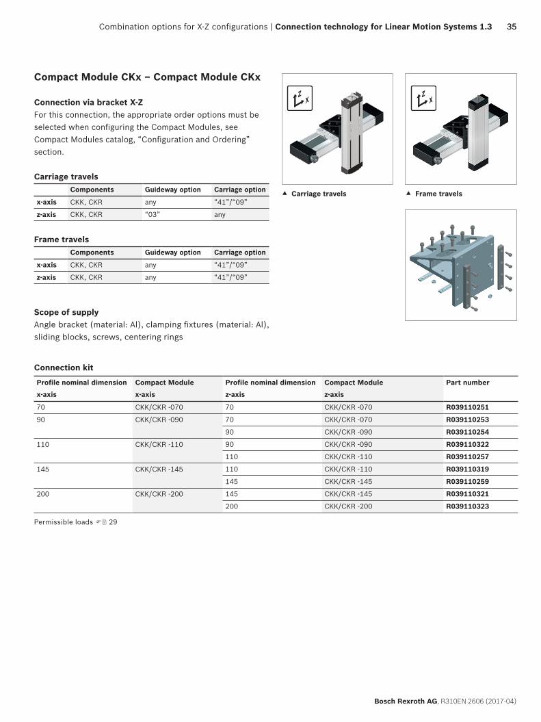
Compact Module CKx – Compact Module CKx
End-face connection X-ZFor this connection, the appropriate order options must be selected when configuring the Compact Modules, see Compact Modules catalog, “Components and Ordering” section.
Carriage travelsComponents Guideway option Carriage option
x-axis CKK, CKR “03” any
z-axis CKK, CKR “03” any
Frame travelsComponents Guideway option Carriage option
x-axis CKK, CKR “03” any
z-axis CKK, CKR any “41”/“09”
Scope of supplyConnection plate (material: Al), clamping fixtures (material: Al), screws, centering rings
1) Shown without Compact Module
Permissible loads 29
Combination options for X-Z configurations
ZX
ZX
3535
Bosch Rexroth AG, R310EN 2606 (2017-04)
Combination options for X-Z configurations | Connection technology for Linear Motion Systems 1.3
c Carriage travels c Frame travels
Connection kit
Profile nominal dimension Compact Module Profile nominal dimension Compact Module Part numberx-axis x-axis z-axis z-axis
70 CKK/CKR -070 70 CKK/CKR -070 R039110251
90 CKK/CKR -090 70 CKK/CKR -070 R039110253
90 CKK/CKR -090 R039110254
110 CKK/CKR -110 90 CKK/CKR -090 R039110322
110 CKK/CKR -110 R039110257
145 CKK/CKR -145 110 CKK/CKR -110 R039110319
145 CKK/CKR -145 R039110259
200 CKK/CKR -200 145 CKK/CKR -145 R039110321
200 CKK/CKR -200 R039110323
Compact Module CKx – Compact Module CKx
Connection via bracket X-ZFor this connection, the appropriate order options must be selected when configuring the Compact Modules, see Compact Modules catalog, “Configuration and Ordering” section.
Carriage travelsComponents Guideway option Carriage option
x-axis CKK, CKR any “41”/“09”
z-axis CKK, CKR “03” any
Frame travelsComponents Guideway option Carriage option
x-axis CKK, CKR any “41”/“09”
z-axis CKK, CKR any “41”/“09”
Scope of supplyAngle bracket (material: Al), clamping fixtures (material: Al), sliding blocks, screws, centering rings
Permissible loads 29

F
D E
A
B
D
20C
36
Bosch Rexroth AG, R310EN 2606 (2017-04)
Connection technology for Linear Motion Systems 1.3 | Combination options for X-Z configurations
Profile nominal dimension Profile nominal dimension Part number A B C D E F m x-axis z-axis (mm) (mm) (mm) (mm) (mm) (mm) (kg)
70 70 R039110251 139.5 106.5 40.0 105.0 105.0 100.0 0.6
90 70 R039110253 157.5 114.5 40.0 106.0 118.0 100.0 0.8
90 R039110254 174.0 131.0 40.0 117.5 133.5 115.0 1.1
110 90 R039110322 188.0 137.0 40.0 125.0 138.0 115.0 1.2
110 R039110257 200.0 149.0 80.0 142.0 155.0 145.0 1.6
145 110 R039110319 241.0 172.0 80.0 155.0 183.0 145.0 2.6
145 R039110259 261.5 193.5 80.0 155.0 183.0 180.0 3.2
200 145 R039110321 332.0 235.0 80.0 200.0 277.0 190.0 6.8
200 R039110323 373.5 279.0 80.0 270.0 288.5 250.0 9.8
Frame travels
D
20C
D E
A
B
F
3737
Bosch Rexroth AG, R310EN 2606 (2017-04)
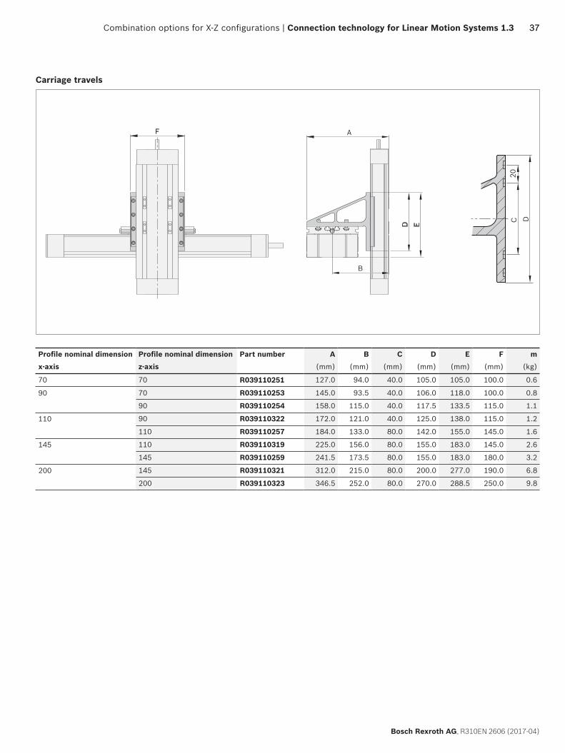
Combination options for X-Z configurations | Connection technology for Linear Motion Systems 1.3
Profile nominal dimension Profile nominal dimension Part number A B C D E F mx-axis z-axis (mm) (mm) (mm) (mm) (mm) (mm) (kg)
70 70 R039110251 127.0 94.0 40.0 105.0 105.0 100.0 0.6
90 70 R039110253 145.0 93.5 40.0 106.0 118.0 100.0 0.8
90 R039110254 158.0 115.0 40.0 117.5 133.5 115.0 1.1
110 90 R039110322 172.0 121.0 40.0 125.0 138.0 115.0 1.2
110 R039110257 184.0 133.0 80.0 142.0 155.0 145.0 1.6
145 110 R039110319 225.0 156.0 80.0 155.0 183.0 145.0 2.6
145 R039110259 241.5 173.5 80.0 155.0 183.0 180.0 3.2
200 145 R039110321 312.0 215.0 80.0 200.0 277.0 190.0 6.8
200 R039110323 346.5 252.0 80.0 270.0 288.5 250.0 9.8
Carriage travels
ZX
38
Bosch Rexroth AG, R310EN 2606 (2017-04)
Connection technology for Linear Motion Systems 1.3 | Combination options for X-Z configurations
Connection kit
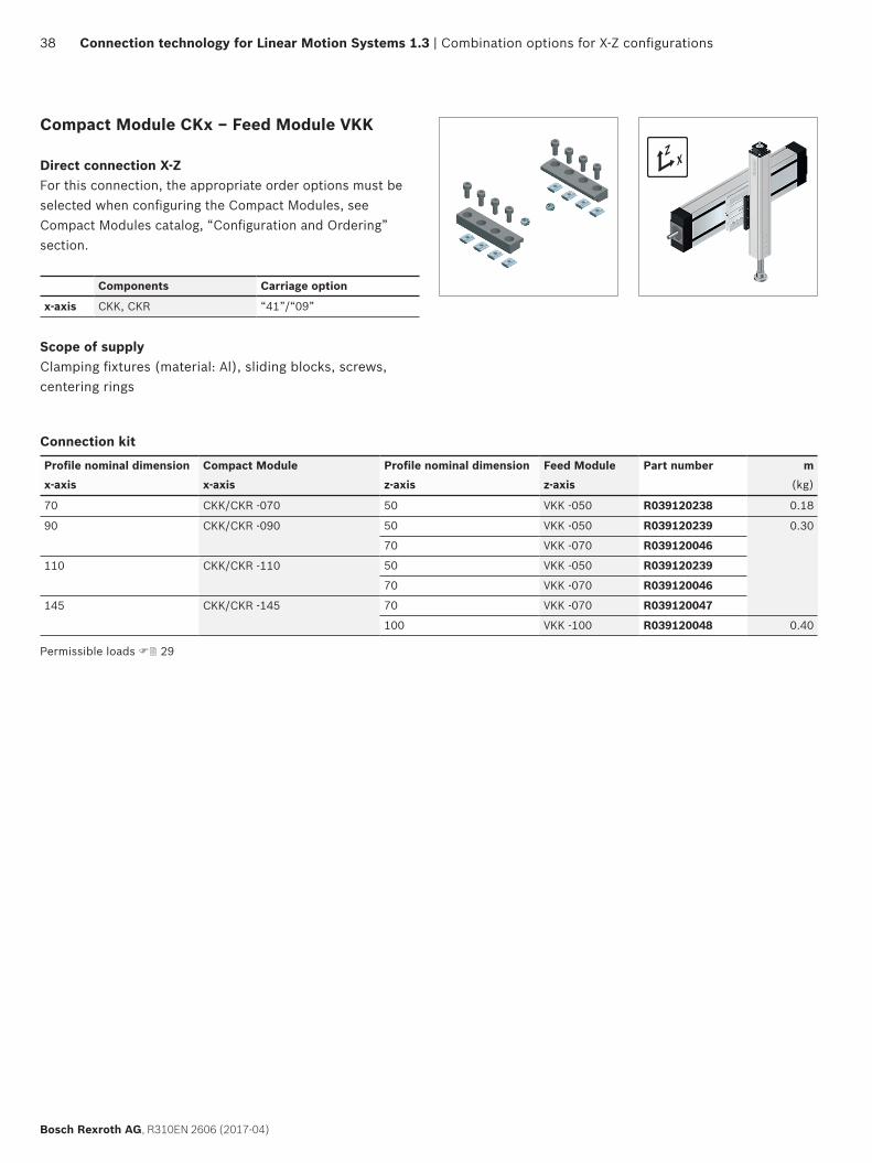
Profile nominal dimension Compact Module Profile nominal dimension Feed Module Part number mx-axis x-axis z-axis z-axis (kg)
70 CKK/CKR -070 50 VKK -050 R039120238 0.18
90 CKK/CKR -090 50 VKK -050 R039120239 0.30
70 VKK -070 R039120046
110 CKK/CKR -110 50 VKK -050 R039120239
70 VKK -070 R039120046
145 CKK/CKR -145 70 VKK -070 R039120047
100 VKK -100 R039120048 0.40
Compact Module CKx – Feed Module VKK
Direct connection X-ZFor this connection, the appropriate order options must be selected when configuring the Compact Modules, see Compact Modules catalog, “Configuration and Ordering” section.
Components Carriage option
x-axis CKK, CKR “41”/“09”
Scope of supplyClamping fixtures (material: Al), sliding blocks, screws, centering rings
Permissible loads 29

F
D
E20
Z
Z–Z 1)
Z
C
A
B
ZX
3939
Bosch Rexroth AG, R310EN 2606 (2017-04)
Combination options for X-Z configurations | Connection technology for Linear Motion Systems 1.3
1) Shown without Feed Module
Connection kit
Profile nominal dimension Compact Module Profile nominal dimension Feed Module Part numberx-axis x-axis z-axis z-axis
70 CKK/CKR -070 50 VKK -050 R039120228
90 CKK/CKR -090 50 VKK -050 R039120227
70 VKK -070 R039120206
110 CKK/CKR -110 70 VKK -070 R039120207
100 VKK -100 R039120208
145 CKK/CKR -145 100 VKK -100 R039120209
Compact Module CKx – Feed Module VKK
End-face connection X-ZFor this connection, the appropriate order options must be selected when configuring the Compact Modules, see Compact Modules catalog, “Configuration and Ordering” section.
Components Guideway option
x-axis CKK, CKR "03"
Scope of supplyConnection plate (material: Al), clamping fixtures (material: Al), screws, centering rings
Profile nominal dimension Profile nominal dimension Part number A B C D E F mx-axis z-axis (mm) (mm) (mm) (mm) (mm) (mm) (kg)
70 50 R039120228 83.0 122.0 69.0 69.5 20.0 15.0 0.7
90 50 R039120227 103.0 155.0 110.0 89.0 20.0 40.0 1.4
70 R039120206 103.0 157.0 110.0 89.0 20.0 40.0 1.4
110 70 R039120207 129.0 198.0 110.0 109.0 40.0 40.0 1.8
100 R039120208 129.0 198.0 110.0 109.0 40.0 40.0 1.8
145 100 R039120209 140.0 209.0 111.0 144.0 80.0 50.0 3.0
Permissible loads 29

ZX
40
Bosch Rexroth AG, R310EN 2606 (2017-04)
Connection technology for Linear Motion Systems 1.3 | Combination options for X-Z configurations
Connection kit
Profile nominal dimension Compact Module Profile nominal dimension Feed Module Part numberx-axis x-axis z-axis z-axis
70 CKK/CKR -070 50 VKK -050 R039110251
90 CKK/CKR -090 50 VKK -050 R039110253
70 VKK -070 R039110317
110 CKK/CKR -110 50 VKK -050 R039110316
70 VKK -070 R039110318
145 CKK/CKR -145 70 VKK -070 R039110319
100 VKK -100 R039110320
200 CKK/CKR -200 100 VKK -100 R039110321
Compact Module CKx – Feed Module VKK
Connection via bracket X-ZFor this connection, the appropriate order options must be selected when configuring the Compact Modules, see Compact Modules catalog, “Configuration and Ordering” section.
Components Carriage option
x-axis CKK, CKR “41”/“09”
Scope of supplyAngle bracket (material: Al), clamping fixtures (material: Al), sliding blocks, screws, centering rings
Permissible loads 29

D
20C
BA
ED
F
4141
Bosch Rexroth AG, R310EN 2606 (2017-04)
Combination options for X-Z configurations | Connection technology for Linear Motion Systems 1.3
Profile nominal dimension Profile nominal dimension Part number A B C D E F mx-axis z-axis (mm) (mm) (mm) (mm) (mm) (kg)
70 50 R039110251 145.0 87.0 40.0 105.0 105.0 100.0 0.6
90 50 R039110253 163.0 95.0 40.0 106.0 118.0 100.0 0.8
70 R039110317 188.0 110.0 40.0 117.5 133.5 115.0 1.1
110 50 R039110316 182.0 106.0 40.0 125.0 138.0 115.0 1.2
70 R039110318 202.0 116.0 40.0 125.0 138.0 115.0 1.2
145 70 R039110319 245.0 141.0 80.0 155.0 183.0 145.0 2.6
100 R039110320 275.0 156.0 80.0 155.0 183.0 145.0 2.6
200 100 R039110321 347.0 200.0 80.0 200.0 277.0 190.0 6.8
C
F
A
B
ZX
C
F
A
B
42
Bosch Rexroth AG, R310EN 2606 (2017-04)
Connection technology for Linear Motion Systems 1.3 | Combination options for X-Z configurations
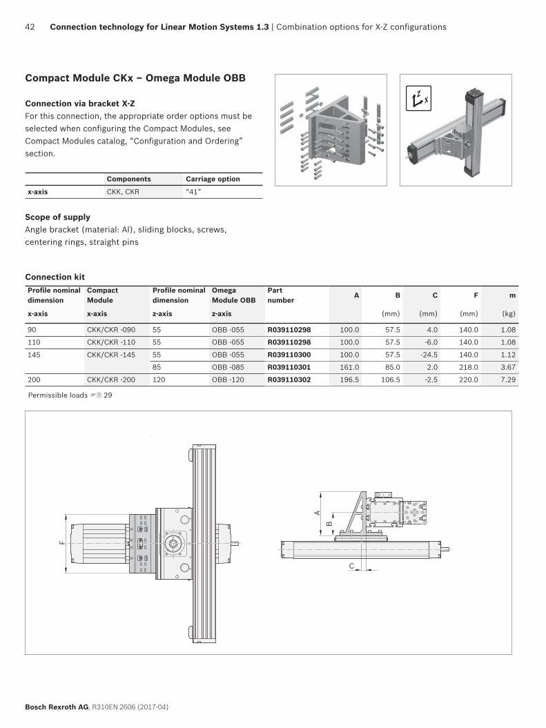
Connection kitProfile nominal dimension
Compact Module
Profile nominal dimension
Omega Module OBB
Part number
A B C F m
x-axis x-axis z-axis z-axis (mm) (mm) (mm) (kg)
90 CKK/CKR -090 55 OBB -055 R039110298 100.0 57.5 4.0 140.0 1.08
110 CKK/CKR -110 55 OBB -055 R039110298 100.0 57.5 -6.0 140.0 1.08
145 CKK/CKR -145 55 OBB -055 R039110300 100.0 57.5 -24.5 140.0 1.12
85 OBB -085 R039110301 161.0 85.0 2.0 218.0 3.67
200 CKK/CKR -200 120 OBB -120 R039110302 196.5 106.5 -2.5 220.0 7.29
Compact Module CKx – Omega Module OBB
Connection via bracket X-ZFor this connection, the appropriate order options must be selected when configuring the Compact Modules, see Compact Modules catalog, “Configuration and Ordering” section.
Components Carriage option
x-axis CKK, CKR “41”
Scope of supplyAngle bracket (material: Al), sliding blocks, screws, centering rings, straight pins
Permissible loads 29

ZXY Y
Z XX
DC
BE
A
4343
Bosch Rexroth AG, R310EN 2606 (2017-04)
Combination options for X-Z configurations | Connection technology for Linear Motion Systems 1.3
Connection kit
Profile nominal dimension Omega Module Size Feed Module Part number A B C D E mx-axis x-axis z-axis z-axis (mm) (mm) (mm) (mm) (mm) (kg)
55 OBB -055 50 VKK -050 R039110283 110.0 36.0 40.0 160.0 78.0 0.62
85 OBB -085 70 VKK -070 R039110284 161.0 50.0 76.0 218.0 105.0 2.00
120 OBB -120 100 VKK -100 R039110285 215.0 69.0 96.0 290.0 135.0 3.65
Omega Module OBB – Feed Module VKK
Connection via bracket X-Z
Scope of supplyEnd-face plate (material: Al), angle bracket (material: Al), threaded anchor strips, screws, centering rings
Permissible loads 30

BD
C
A
E
ZX
BD
C
A
E
44
Bosch Rexroth AG, R310EN 2606 (2017-04)
Connection technology for Linear Motion Systems 1.3 | Combination options for X-Z configurations
Linear Module MKx – Linear Module MKx
Connection via bracket X-ZCarriage travels
Linear Module version for x-axis: X Carriage with T-slots
Scope of supplyAngle bracket, threaded anchor strips, clamping fixtures, socket head cap screws
Connection kit
Profile nominal dimension Linear Module Profile nominal dimension Linear Module Part numberx-axis x-axis z-axis z-axis
80 MKK/MKR -080, MLR -080 65 MKK/MKR -065 R039110060
80 MKK/MKR -080, MLR -080
110 MKK/MKR -110, MLR -110 80 MKK/MKR -080, MLR -080 R039110055
110 MKK/MKR -110, MLR -110 R039110053
145 MKR -145 110 MKK/MKR -110, MLR -110 R039110052
165 MKK/MKR -165 110 MKK/MKR -110, MLR -110 R039110052
165 MKK/MKR -165 R039110050
Profile nominal dimension Profile nominal dimension Part number A B C D E mx-axis z-axis (mm) (mm) (mm) (mm) (mm) (kg)
80 65 R039110060 279.0 160.0 120.0 99.5 89.0 2.50
80
110 80 R039110055 279.0 160.0 120.0 107.5 89.0 2.50
110 R039110053
145 110 R039110052 327.5 224.0 165.0 141.0 106.0 5.80
165 110 R039110052 327.5 224.0 165.0 143.0 106.0 5.80
165 R039110050
c Carriage travels
Permissible loads 30
ZXY Y
Z XX
A
E
CB
D
4545
Bosch Rexroth AG, R310EN 2606 (2017-04)
Combination options for X-Z configurations | Connection technology for Linear Motion Systems 1.3
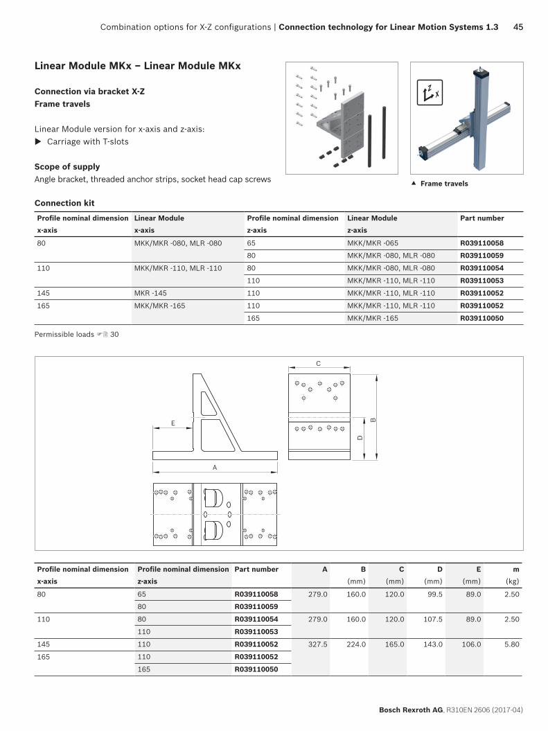
Linear Module MKx – Linear Module MKx
Connection via bracket X-ZFrame travels
Linear Module version for x-axis and z-axis: X Carriage with T-slots
Scope of supplyAngle bracket, threaded anchor strips, socket head cap screws
Connection kit
Profile nominal dimension Linear Module Profile nominal dimension Linear Module Part numberx-axis x-axis z-axis z-axis
80 MKK/MKR -080, MLR -080 65 MKK/MKR -065 R039110058
80 MKK/MKR -080, MLR -080 R039110059
110 MKK/MKR -110, MLR -110 80 MKK/MKR -080, MLR -080 R039110054
110 MKK/MKR -110, MLR -110 R039110053
145 MKR -145 110 MKK/MKR -110, MLR -110 R039110052
165 MKK/MKR -165 110 MKK/MKR -110, MLR -110 R039110052
165 MKK/MKR -165 R039110050
c Frame travels
Permissible loads 30
Profile nominal dimension Profile nominal dimension Part number A B C D E mx-axis z-axis (mm) (mm) (mm) (mm) (kg)
80 65 R039110058 279.0 160.0 120.0 99.5 89.0 2.50
80 R039110059
110 80 R039110054 279.0 160.0 120.0 107.5 89.0 2.50
110 R039110053
145 110 R039110052 327.5 224.0 165.0 143.0 106.0 5.80
165 110 R039110052
165 R039110050

YX
YX
46
Bosch Rexroth AG, R310EN 2606 (2017-04)
Connection technology for Linear Motion Systems 1.3 | Combination options for X-Y configurations
c Frame travels c Carriage travels
Connection kit
Profile nominal dimension Compact Module Profile nominal dimension Compact Module Part number
x-axis x-axis y-axis y-axis70 CKK/CKR -070 70 CKK/CKR -070 R039120238
90 CKK/CKR -090 70 CKK/CKR -070 R039120239
90 CKK/CKR -090 R039120045
110 CKK/CKR -110 70 CKK/CKR -070 R039120239
90 CKK/CKR -090 R039120045
110 CKK/CKR -110 R039120046
145 CKK/CKR -145 90 CKK/CKR -090 R039120242
110 CKK/CKR -110 R039120047
145 CKK/CKR -145 R039120048
200 CKK/CKR -200 145 CKK/CKR -145 R039120049
200 CKK/CKR -200 R039120145
Compact Module CKx – Compact Module CKx
Direct connection X-Y(Can also be used as an X-Z connection)For this connection, the appropriate order options must be selected when configuring the Compact Modules, see Compact Modules catalog, “Configuration and Ordering” section.
Carriage travelsComponents Guideway option Carriage option
x-axis CKK, CKR any “41” / “09”
y-axis CKK, CKR mounting-dependent any
Frame travelsComponents Guideway option Carriage option
x-axis CKK, CKR any “41” / “09”
y-axis CKK, CKR any “41” / “09”
Scope of supplyClamping fixtures (material: Al), sliding blocks, screws, centering rings
Permissible loads 30
Combination options for X-Y configurations

AA
4747
Bosch Rexroth AG, R310EN 2606 (2017-04)
Combination options for X-Y configurations | Connection technology for Linear Motion Systems 1.3
Profile nominal dimension Profile nominal dimension Part number A m
x-axis y-axis (mm) (kg)
70 70 R039120238 76.5 0.18
90 70 R039120239 88.0 0.20
90 R039120045 96.0 0.20
110 70 R039120239 98.0 0.30
90 R039120045 106.0 0.20
110 R039120046 116.0 0.30
145 90 R039120242 125.0 0.30
110 R039120047 135.0 0.30
145 R039120048 150.0 0.40
200 145 R039120049 192.0 0.40
200 R039120145 227.0 0.80
Profile nominal dimension Profile nominal dimension Part number A m
x-axis y-axis (mm) (kg)
70 70 R039120238 89.0 0.18
90 70 R039120239 100.5 0.20
90 R039120045 112.0 0.20
110 70 R039120239 98.0 0.30
90 R039120045 122.0 0.20
110 R039120046 132.0 0.30
145 90 R039120242 125.0 0.30
110 R039120047 151.0 0.30
145 R039120048 170.0 0.40
200 145 R039120049 212.0 0.40
200 R039120145 254.0 0.80
Carriage travels
Frame travels

YX
YX
48
Bosch Rexroth AG, R310EN 2606 (2017-04)
Connection technology for Linear Motion Systems 1.3 | Combination options for X-Y configurations
c Carriage travels
Connection kit
Profile nominal dimension Compact Module Profile nominal dimension Compact Module Part numberx-axis x-axis y-axis y-axis
70 CKK/CKR -070 70 CKK/CKR -070 R039110252
90 CKK/CKR -090 70 CKK/CKR -070 R039110324
90 CKK/CKR -090 R039110255
110 CKK/CKR -110 R039110325
110 CKK/CKR -110 90 CKK/CKR -090 R039110255
110 CKK/CKR -110 R039110256
145 CKK/CKR -145 R039110327
145 CKK/CKR -145 110 CKK/CKR -110 R039110326
145 CKK/CKR -145 R039110258
200 CKK/CKR -200 145 CKK/CKR -145 R039110328
200 CKK/CKR -200 R039110329
Compact Module CKx – Compact Module CKx
Connection via bracket X-Y(Can also be used as an X-Z connection)For this connection, the appropriate order options must be selected when configuring the Compact Modules, see Compact Modules catalog, “Configuration and Ordering” section.
Carriage travelsComponents Guideway option Carriage option
x-axis CKK, CKR any “41” / “09”
y-axis CKK, CKR mounting-dependent any
Frame travelsComponents Guideway option Carriage option
x-axis CKK, CKR any “41” / “09”
y-axis CKK, CKR any “41” / “09”
Scope of supplyConnection bracket (material: Al), clamping fixtures (material: Al), sliding blocks, screws, centering rings
c Frame travels
Permissible loads 30
A
B
C
D
X
D
X 1)
E20
F M(3x)
min
. 8 25G
A
B
C
D
X
D
X 1)
E20
F M(3x)
min
. 8 25G
4949
Bosch Rexroth AG, R310EN 2606 (2017-04)
Combination options for X-Y configurations | Connection technology for Linear Motion Systems 1.3
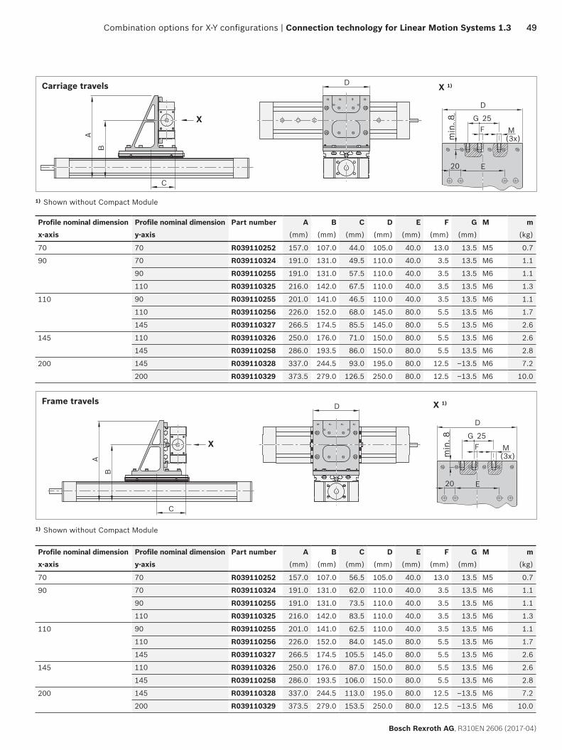
Carriage travels
Profile nominal dimension Profile nominal dimension Part number A B C D E F G M mx-axis y-axis (mm) (mm) (mm) (mm) (mm) (mm) (mm) (kg)
70 70 R039110252 157.0 107.0 44.0 105.0 40.0 13.0 13.5 M5 0.7
90 70 R039110324 191.0 131.0 49.5 110.0 40.0 3.5 13.5 M6 1.1
90 R039110255 191.0 131.0 57.5 110.0 40.0 3.5 13.5 M6 1.1
110 R039110325 216.0 142.0 67.5 110.0 40.0 3.5 13.5 M6 1.3
110 90 R039110255 201.0 141.0 46.5 110.0 40.0 3.5 13.5 M6 1.1
110 R039110256 226.0 152.0 68.0 145.0 80.0 5.5 13.5 M6 1.7
145 R039110327 266.5 174.5 85.5 145.0 80.0 5.5 13.5 M6 2.6
145 110 R039110326 250.0 176.0 71.0 150.0 80.0 5.5 13.5 M6 2.6
145 R039110258 286.0 193.5 86.0 150.0 80.0 5.5 13.5 M6 2.8
200 145 R039110328 337.0 244.5 93.0 195.0 80.0 12.5 –13.5 M6 7.2
200 R039110329 373.5 279.0 126.5 250.0 80.0 12.5 –13.5 M6 10.0
1) Shown without Compact Module
Frame travels
min
. 8m
in. 8
Profile nominal dimension Profile nominal dimension Part number A B C D E F G M mx-axis y-axis (mm) (mm) (mm) (mm) (mm) (mm) (mm) (kg)
70 70 R039110252 157.0 107.0 56.5 105.0 40.0 13.0 13.5 M5 0.7
90 70 R039110324 191.0 131.0 62.0 110.0 40.0 3.5 13.5 M6 1.1
90 R039110255 191.0 131.0 73.5 110.0 40.0 3.5 13.5 M6 1.1
110 R039110325 216.0 142.0 83.5 110.0 40.0 3.5 13.5 M6 1.3
110 90 R039110255 201.0 141.0 62.5 110.0 40.0 3.5 13.5 M6 1.1
110 R039110256 226.0 152.0 84.0 145.0 80.0 5.5 13.5 M6 1.7
145 R039110327 266.5 174.5 105.5 145.0 80.0 5.5 13.5 M6 2.6
145 110 R039110326 250.0 176.0 87.0 150.0 80.0 5.5 13.5 M6 2.6
145 R039110258 286.0 193.5 106.0 150.0 80.0 5.5 13.5 M6 2.8
200 145 R039110328 337.0 244.5 113.0 195.0 80.0 12.5 –13.5 M6 7.2
200 R039110329 373.5 279.0 153.5 250.0 80.0 12.5 –13.5 M6 10.0
1) Shown without Compact Module

C
A
B
D
20 20
M(3x)
min
. 8
25 H
G
E F
X
X1)
YX
min
. 8
50
Bosch Rexroth AG, R310EN 2606 (2017-04)
Connection technology for Linear Motion Systems 1.3 | Combination options for X-Y configurations
Connection kit
Profile nominal dimension Compact Module Profile nominal dimension Compact Module Bracket orientation Part numberx-axis x-axis y-axis y-axis
70 CKK/CKR -070 70 CKK/CKR -070 Right-hand R039110280
90 CKK/CKR -090 70 CKK/CKR -070 Right-hand R039110278
90 CKK/CKR -090 Right-hand R039110174
110 CKK/CKR -110 90 CKK/CKR -090 Right-hand R039110174
110 CKK/CKR -110 Right-hand R039110175
145 CKK/CKR -145 110 CKK/CKR -110 Right-hand R039110176
145 CKK/CKR -145 Right-hand R039110177
Compact Module CKx – Compact Module CKx
Connection via bracket X-Y (reinforced right-hand version) For this connection, the appropriate order options must be selected when configuring the Compact Modules, see Compact Modules catalog, “Configuration and Ordering” section.
Components Guideway option Carriage option
x-axis CKK, CKR any “41” / “09”
y-axis CKK, CKR mounting-dependent any
Scope of supplyConnection bracket (material: Al), clamping fixtures (material: Al), sliding blocks, screws, centering rings
Right-hand bracket
Profile nominal dimension x-axis
Profile nominal dimension y-axis
Part number A B C D E F G H M m(mm) (mm) (mm) (mm) (mm) (mm) (mm) (mm) (kg)
70 70 R039110280 159.5 109.5 43.0 162.0 4.0 96.0 9.0 13.5 M5 1.0
90 70 R039110278 171.0 121.0 43.0 162.0 14.0 86.0 –1.0 13.5 M5 1.0
90 R039110174 191.0 131.0 57.5 180.0 15.0 105.0 5.0 13.5 M6 1.5
110 90 R039110174 201.0 141.0 57.5 190.0 15.0 105.0 5.0 13.5 M6 1.5
110 R039110175 226.0 152.0 68.0 220.0 25.0 135.0 5.0 – 13.5 M6 2.0
145 110 R039110176 249.0 176.0 70.5 290.0 40.0 160.0 12.5 – 13.5 M6 4.0
145 R039110177 285.5 193.5 85.5 290.0 40.0 160.0 12.5 – 13.5 M6 4.4
1) Shown without Compact Module
Permissible loads 32

YX
20 20
M(3x) m
in. 8
25H
G
EF
X1)
C
D
A
B
X
min
. 8
5151
Bosch Rexroth AG, R310EN 2606 (2017-04)
Combination options for X-Y configurations | Connection technology for Linear Motion Systems 1.3
Compact Module CKx – Compact Module CKx
Connection via bracket X-Y(reinforced left-hand version)For this connection, the appropriate order options must be selected when configuring the Compact Modules, see Compact Modules catalog, “Configuration and Ordering” section.
Components Guideway option Carriage option
x-axis CKK, CKR any “41” / “09”
y-axis CKK, CKR mounting-dependent any
Scope of supplyConnection bracket (material: Al), clamping fixtures (material: Al), sliding blocks, screws, centering rings
Connection kit
Profile nominal dimension Compact Module Profile nominal dimension Compact Module Bracket orientation Part numberx-axis x-axis y-axis y-axis
70 CKK/CKR -070 70 CKK/CKR -070 Left-hand R039110281
90 CKK/CKR -090 70 CKK/CKR -070 Left-hand R039110279
90 CKK/CKR -090 Left-hand R039110180
110 CKK/CKR -110 90 CKK/CKR -090 Left-hand R039110180
110 CKK/CKR -110 Left-hand R039110181
145 CKK/CKR -145 110 CKK/CKR -110 Left-hand R039110182
145 CKK/CKR -145 Left-hand R039110183
Permissible loads 32
Left-hand bracket
Profile nominal dimension x-axis
Profile nominal dimension y-axis
Part number A B C D E F G H M m(mm) (mm) (mm) (mm) (mm) (mm) (mm) (mm) (kg)
70 70 R039110281 159.5 109.5 43.0 162.0 4.0 96.0 9.0 13.5 M5 1.0
90 70 R039110279 171.0 121.0 43.0 162.0 14.0 86.0 –1.0 13.5 M5 1.0
90 R039110180 191.0 131.0 57.5 180.0 15.0 105.0 5.0 13.5 M6 1.5
110 90 R039110180 201.0 141.0 57.5 190.0 15.0 105.0 5.0 13.5 M6 1.5
110 R039110181 226.0 152.0 68.0 220.0 25.0 135.0 5.0 – 13.5 M6 2.0
145 110 R039110182 249.0 176.0 70.5 290.0 40.0 160.0 12.5 – 13.5 M6 4.0
145 R039110183 285.5 193.5 85.5 290.0 40.0 160.0 12.5 – 13.5 M6 4.4
1) without Compact Module

YX
52
Bosch Rexroth AG, R310EN 2606 (2017-04)
Connection technology for Linear Motion Systems 1.3 | Combination options for X-Y configurations
Connection kit
Profile nominal dimension Linear Module Profile nominal dimension Compact Module Part number 1)
x-axis x-axis y-axis y-axis40 MKK/MKR -040 70 CKK/CKR -070 R039110211
90 CKK/CKR -090 R039110212
65 MKK -065 90 CKK/CKR -090 R039110264
110 CKK/CKR -110 R039110266
80 MKK/MKR -080 110 CKK/CKR -110 R039110268
145 CKK/CKR -145 R039110270
110 MKR -110 145 CKK/CKR -145 R039110272
200 CKK/CKR -200 R039110274
Linear Module MKx – Compact Module CKx
Connection via brackets 2X-Y Linear Module MKx carriage with threadsFor this connection, the appropriate order options must be selected when configuring the Compact Modules and Linear Modules, see Compact Modules and Linear Modules catalogs, “Configuration and Ordering” section.
Components Guideway option Carriage optionx-axis MKx any long version,
if selectable
y-axis CKx “03” / “04” any
Scope of supplyConnection bracket (material: Al), clamping fixtures (material: Al), screws, centering ringsfor CKx -200: Connection bracket (material: Al), screws, centering rings, washers, sliding blocks
1) Please order 2 units for 2X-Y connections
c 2X-Y connection
Permissible loads 32
c CKx -200 adapted with sliding blocks

A
B
C
D
X
DX2)
E
5353
Bosch Rexroth AG, R310EN 2606 (2017-04)
Combination options for X-Y configurations | Connection technology for Linear Motion Systems 1.3
Profile nominal dimension Profile nominal dimension Part number A B C D E mx-axis y-axis (mm) (mm) (mm) (mm) (mm) (kg)
40 70 R039110211 169.5 119.5 -6.0 80.0 20.0 0.60
90 R039110212 187.0 127.0 5.0 92.0 40.0 0.90
65 90 R039110264 221.5 161.0 2.0 140.0 40.0 1.25
110 R039110266 245.5 171.0 2.0 145.0 40.0 1.50
80 110 R039110268 260.5 186.0 23.0 145.0 40.0
145 R039110270 301.0 208.5 26.0 175.0 40.0 2.80
110 145 R039110272 330.0 237.5 31.0 175.0 40.0
200 R039110274 377.0 285.0 38.0 245.0 40.0 8.80
2) without Compact Module

YX
54
Bosch Rexroth AG, R310EN 2606 (2017-04)
Connection technology for Linear Motion Systems 1.3 | Combination options for X-Y configurations
Connection kit
Profile nominal dimension Linear Module Profile nominal dimension Compact Module Part number 1)
x-axis x-axis y-axis y-axis65 MKK/MKR -065 90 CKK/CKR -090 R039110265
110 CKK/CKR -110 R039110267
80 MKK/MKR -080, MLR -080 110 CKK/CKR -110 R039110269
145 CKK/CKR -145 R039110271
110 MKK/MKR -110, MLR -110 145 CKK/CKR -145 R039110273
200 CKK/CKR -200 R039110275
165 MKK/MKR -165 200 CKK/CKR -200 R039110276
Linear Module MKx – Compact Module CKx
Connection via brackets 2X-Y Linear Module MKx - carriage with T-slotsFor this connection, the appropriate order options must be selected when configuring the Compact Modules and Linear Modules, see Compact Modules and Linear Modules catalogs, “Configuration and Ordering” section.
Components Guideway option Carriage optionx-axis MKx any long version,
if selectable
y-axis CKx mounting-dependent any
Scope of supplyConnection bracket (material: Al), clamping fixtures (material: Al), screws, centering rings, washers, sliding blocks for CKx -200: Connection bracket (material: Al), screws, centering rings, washers, sliding blocks
c CKx -200 adapted with sliding blocks
c 2X-Y connection
1) Please order 2 units for 2X-Y connections
Permissible loads 32

A
B
C
D
X
DX2)
E
5555
Bosch Rexroth AG, R310EN 2606 (2017-04)
Combination options for X-Y configurations | Connection technology for Linear Motion Systems 1.3
Profile nominal dimension Profile nominal dimension Part number A B C D E mx-axis y-axis (mm) (mm) (mm) (mm) (mm) (kg)
65 90 R039110265 221.5 161.0 2.0 140.0 40.0 1.30
110 R039110267 245.5 171.0 2.0 145.0 40.0 1.60
80 110 R039110269 260.5 186.0 23.0 145.0 40.0
145 R039110271 301.0 208.5 26.0 175.0 40.0 2.90
110 145 R039110273 330.0 237.5 31.0 175.0 40.0
200 R039110275 377.0 285.0 38.0 245.0 40.0 9.00
165 200 R039110276 443.0 351.0 0.0 245.0 40.0 9.40
2) without Compact Module

YX
AA
A–A
A
C
B
56
Bosch Rexroth AG, R310EN 2606 (2017-04)
Connection technology for Linear Motion Systems 1.3 | Combination options for X-Y configurations
Linear Module MKx – Linear Module MKx
Connection with plate 2X-Y(with clamping fixture)
Components Carriage optionx-axis MKx Carriage, with T-slot
y-axis MKx any
Scope of supplyConnection plate, anchor strips, clamping fixtures, socket head cap screws
Permissible loads 32
1) Please order 2 units for 2X-Y connections
Connection kit
Profile nominal dimension
Linear Module Profile nominal dimension
Linear Module Part number1)A B C m
x-axis x-axis y-axis y-axis (mm) (mm) (mm) (kg)
65 MKK/MKR -065 65 MKK/MKR -065 R039120057 18.0 115.0 196.0 1.20
80 MKK/MKR -080,MLR -080
65 MKK/MKR -065 R039120056 18.0 138.0 210.0 1.45
80 MKK/MKR -080, MLR -080 R039120056
110MKK/MKR -110,MLR -110
80 MKK/MKR -080, MLR -080 R039120004 18.0 138.0 220.0 1.50
165 MKK/MKR -165 110 MKK/MKR -110, MLR -110 R039120001 25.0 163.0 320.0 3.50
145 MKR -145 R039120051 25.0 230.0 410.0 6.70
165 MKK/MKR -165 R039120050

YX
AA
A–A
A
C
B
5757
Bosch Rexroth AG, R310EN 2606 (2017-04)
Combination options for X-Y configurations | Connection technology for Linear Motion Systems 1.3
Linear Module MKx – Linear Module MKx
Connection with plate 2X-Y(without clamping fixture)
Components Carriage optionx-axis MKx Carriage, with T-slot
y-axis MKx any
Scope of supplyConnection plate, threaded anchor strips, socket head cap screws
Connection kit
Profile nominal dimension
Linear Module Profile nominal dimension
Linear Module Part number1)A B C m
x-axis x-axis y-axis y-axis (mm) (mm) (mm) (kg)
110 MKK/MKR -110, MLR -110 110 MKK/MKR -110, MLR -110 R039120003 18.0 138.0 220.0 1.50
145 MKR -145 110 R039120055 25.0 230.0 360.0 5.60
165 MKK/MKR -165 110 R039120002 25.0 163.0 320.0 3.50
165 MKK/MKR -165 R039120000
Permissible loads 33
1) Please order 2 units for 2X-Y connections

YX
YX
58
Bosch Rexroth AG, R310EN 2606 (2017-04)
Connection technology for Linear Motion Systems 1.3 | Combination options for X-Y configurations
c Carriage travels c Frame travels
Ball Rail Table TKK – Ball Rail Table TKK
Connection with plate X-Y(Can also be used as an X-Z connection)
For this connection the appropriate order options must be selected when configuring the Ball Rail Tables, see Ball Rail Tables catalog, “Configuration and ordering” section.
Guideway option Carriage option
Carriage travels y-axis flat version any
Frame travels y-axis any long version
Scope of supplyCross-plate, straight pins, socket head cap screws, slotted nuts
Connection kit
Profile nominal dimension Ball Rail Table Profile nominal dimension Ball Rail Table Part number Connection typex-axis x-axis y-axis y-axis
155 TKK 15-155 AL 155 TKK 15-155 AL R039120011 Carriage travels
155 TKK 15-155 AL R039120012 Frame travels
225 TKK 20-225 AL 155 TKK 15-155 AL R039120013 Carriage travels
155 TKK 15-155 AL R039120014 Frame travels
225 TKK 20-225 AL R039120015 Carriage travels
225 TKK 20-225 AL R039120016 Frame travels
325 TKK 30-325 AL 225 TKK 20-225 AL R039120017 Carriage travels
225 TKK 20-225 AL R039120018 Frame travels
325 TKK 30-325 AL R039120019 Carriage travels
325 TKK 30-325 AL R039120020 Frame travels
455 TKK 35-455 AL 325 TKK 30-325 AL R039120021 Carriage travels
325 TKK 30-325 AL R039120022 Frame travels
Permissible loads 33

AG
CE
F
B
D
C
5959
Bosch Rexroth AG, R310EN 2606 (2017-04)
Combination options for X-Y configurations | Connection technology for Linear Motion Systems 1.3
Profile nominal dimension Profile nominal dimension Part number A B C D E F G mx-axis y-axis (mm) (mm) (mm) (mm) (mm) (mm) (mm) (kg)
155 155 R039120011 18 165 11.0 77.5 76.5 220 1.8
R039120012
225 155 R039120013 18 220 32.5 77.5 110.0 220 2.4
R039120014
225 R039120015 18 240 16.0 112.5 111.5 320 3.8
R039120016
325 225 R039120017 18 320 47.5 112.5 160.0 320 5.0
R039120018
325 R039120019 25 340 16.0 162.5 161.5 450 10.5
R039120020
455 325 R039120021 25 400 37.5 162.5 200.0 450 12.5
R039120022

60
Bosch Rexroth AG, R310EN 2606 (2017-04)
EasyHandling Connection Technology 1.3 |
Combination options with profiles
Rexroth offers multiple options for fastening axis systems to a base frame.Strut profiles for constructing all kinds of frames, feet for simple fastening to the base frame
Combination options with profiles

6161Combination options with profiles | Connection technology for Linear Motion Systems 1.3
Bosch Rexroth AG, R310EN 2606 (2017-04)
Strut profile: X Space-saving and rigid
design X Positive-locking connec-
tion (centering rings) X Compatible with Basic
Mechanical Elements (MGE) from Rexroth, profile size PB 30 and PB 45
Connection kit: X Direct mounting X Positive-locking connec-
tion (centering rings) X No alignment necessary X minimized installation
effort
Foot: X Simple connection of
strut profile to base frame
X Positive-locking connec-tion (centering rings)
X Compatible with Basic Mechanical Elements (MGE) from Rexroth, profile size PB 30, PB 40 and PB 45
End-face attachment of the linear motion system Side mounting of the linear motion system

L±1
40±0
,01
40±0,01
35N
x 4
0
AA 2040
A - A
40
20
6
6
6
660
60
2,1 Ø9H7
904510
45
10
4510
2,1
9040
Ø12H7L
±1
40
±0,0
1
40±0,01
48N
x 4
0
A
A - A
A
8
1 1
2 2
1
1
1
1
62
Bosch Rexroth AG, R310EN 2606 (2017-04)
Connection technology for Linear Motion Systems 1.3 | Combination options with profiles
Strut profiles 60 x 60, 90 x 90
Aluminum profile, clear anodizedSpace-saving and rigid designStandardized modular dimensions/spacingPositive-locking connection (centering rings)Compatible with Basic Mechanical Elements (MGE) from Rexroth
Strut profile Profile nominal dimension Part number Length m Planar moment of inertia lx = lyStrut profile Lmax (mm) variable (kg) (kg/m) (cm4)
60 x 60 60 R037531036 4000 15.6 48.6R037531037 3.9
90 x 90 R037541030 4000 31.2 230.090 R037541032 7.8
c Strut profile size 60 x 60
c Strut profile size 90 x 90
1 for sliding block 10 mm 2 for sliding block 8 mm

Ø12H7
9
7,5
40
Ø12
H7
9
5084
4050
84
40
40±0,01
45
88
4045
40±0
,01
64
64
37
37
Ø9H
7
40±0,01
Ø5,
5
6
Ø9H7
40±0
.01
Ø5,5
40
4020
40
4020
6363
Bosch Rexroth AG, R310EN 2606 (2017-04)
Combination options with profiles | Connection technology for Linear Motion Systems 1.3
Foot for profile size 60 x 60
Simple connection of strut profile to base frameCompatible with Basic Mechanical Elements (MGE) from Rexroth, profile size PB 20 and PB 40
Scope of supplyFoot angle bracket (material: Al), sliding blocks, screws, centering rings
Foot for profile size 90 x 90
Simple connection of strut profile to base frameCompatible with Basic Mechanical Elements (MGE) from Rexroth, profile size PB 40 and PB 45
Scope of supplyFoot angle bracket (material: Al), sliding blocks, screws, centering rings
Part number m
(kg)
R037530013 0.21
Part number m
(kg)
R037540013 0.71

86
Ø12H7
66 14
115
40
660
152
105
10H8
35
55 759H13
50
40
41
60
Ø9 H7
4
45
38,5 51,56,6H13
30
8H8
107
7485
1051
R037540017R037530017
64
Bosch Rexroth AG, R310EN 2606 (2017-04)
Connection technology for Linear Motion Systems 1.3 | Combination options with profiles
Foot (with webs), adjustable version
Simple connection of strut profile to base frame.Adjustable in one axial direction.The base of the adjustable foot can be aligned in one axial direction. The foot has a groove milled along the centerline of its base (8H8 for profile 60 x 60 and 10H8 for profile 90 x 90). The groove has been widened at each end and provided with threads. Using the pins provided, the foot can be aligned to any required elements at the installation location, such as a key or locating pin.
Scope of supplyFoot (material: Al), sliding blocks, screws, centering rings
Foot Part number m
(kg)
For profile 60 x 60 R037530017 0.6
For profile 90 x 90 R037540017 1.6

6565
Bosch Rexroth AG, R310EN 2606 (2017-04)
Combination options with profiles | Connection technology for Linear Motion Systems 1.3
Strut Profile ‒ Linear Motion System
Direct connectionSide mounting of modulesDirect mountingPositive-locking connection (centering rings)No alignment necessaryMinimizes installation effort
For this connection, the appropriate order options must be selected when configuring the Compact Modules, see Compact Modules catalog, “Configuration and Ordering” section.
Carriage travelsComponents Guideway option Carriage option
CKK, CKR mounting-dependent any
Frame travelsComponents Guideway option Carriage option
CKK, CKR any “41” / “09”
Scope of supplyClamping fixtures (material: Al), sliding blocks, screws, centering rings
Connection kit
Profile nominal dimension, linear motion system
Linear motion system Profile nominal dimension, profile
Profile Part number
40 MKK/MKR -040 60 Strut profile 60 R039120232
50 VKK -050 60 Strut profile 60 R039120232
70 CKK/CKR -070 60 Strut profile 60 R039120232
VKK -070 90 Strut profile 90 R039120142
90 CKK/CKR -090 60 Strut profile 60 R039120233
90 Strut profile 90 R039120141
100 VKK -100 90 Strut profile 90 R039120143
110 CKK/CKR -110 90 Strut profile 90 R039120142
145 CKK/CKR -145 90 Strut profile 90 R039120143
c Feed Module VKK c Compact Module CKx – Carriage travels
c Compact Module CKx – Frame travels
c Linear Module MKx

66
Bosch Rexroth AG, R310EN 2606 (2017-04)
Connection technology for Linear Motion Systems 1.3 | Combination options with profiles
Strut Profile ‒ Linear Motion System
End-face connectionPositive-locking connection (centering rings)No alignment necessaryMinimizes installation effort
For this connection, the appropriate order options must be selected when configuring the Compact Modules, see Compact Modules catalog, “Configuration and Ordering” section.
Carriage travelsComponents Guideway option Carriage option
CKK, CKR mounting-dependent any
Frame travelsComponents Guideway option Carriage option
CKK, CKR any “41” / “09”
Scope of supplyPlate (material: Al), angle bracket, clamping fixtures (material: Al), sliding blocks, screws, centering rings
c Carriage travels c Frame travels

A
BC
D
E
6767
Bosch Rexroth AG, R310EN 2606 (2017-04)
Combination options with profiles | Connection technology for Linear Motion Systems 1.3
Connection kit
Profile nominal dimension
Linear motion system Profile nominal dimension
Strut profile Part number A B C D E m(mm) (mm) (mm) (mm) (mm) (kg)
40 MKK/MKR -040 60 60 R037520012 90 115 16 min. 7/max. 12 30.0 0.7
90 90 R037520005 145 145 20 min. 9/max. 22 42.5 1.6
50 VKK -050 60 60 R037520012 90 115 16 min. 7/max. 12 30.0 0.7
90 90 R037520005 145 145 20 min. 9/max. 22 42.5 1.6
70 CKK/CKR -070 60 60 R037520012 90 115 16 min. 7/max. 12 30.0 0.7
90 90 R037520005 145 145 20 min. 9/max. 22 42.5 1.6
VKK -070 60 60 R037540012 90 115 16 min. 7/max. 12 30.0 0.7
90 90 R037540005 145 145 20 min. 9/max. 22 20.0 1.5
90 CKK/CKR -090 60 60 R037530012 90 115 16 min. 7/max. 12 30.0 0.7
90 90 R037530005 145 145 20 min. 9/max. 22 20.0 1.5
100 VKK -100 90 90 R037550005 145 180 20 min. 9/max. 22 20.0 1.8
110 CKK/CKR -110 90 90 R037540005 145 145 20 min. 9/max. 22 20.0 1.6
145 CKK/CKR -145 90 90 R037550005 145 180 20 min. 9/max. 22 20.0 1.8

68
Bosch Rexroth AG, R310EN 2606 (2017-04)
Connection technology for Linear Motion Systems 1.3 | Combination options with profiles
MGE (Basic Mechanical Elements) – Linear Motion System
Direct connectionDesigned for aluminum profiles from the MGE range with a modular dimension of 40 and 50 mm and a 10 mm T-slot
For this connection, the appropriate order options must be selected when configuring the Compact Modules, see Compact Modules catalog, “Configuration and Ordering” section.
Carriage travelsComponents Guideway option Carriage option
CKK, CKR mounting-dependent any
Frame travelsComponents Guideway option Carriage option
CKK, CKR any “41” / “09”
Scope of supplyClamping fixtures (material: Al), screws, sliding blocks
c Carriage travels c Frame travels
Connection kit
Profile nominal dimension Linear motion system Profile nominal dimension Profile Part number
40 MKK/MKR -040 40 MGE profile 40 R039120236
50 VKK -050 40 MGE profile 40 R039120236
65 MKK/MKR -065 50 MGE profile 50 R039120086
70 VKK -070 40 MGE profile 40 R039120085
50 MGE profile 50 R039120084
CKK/CKR -070 40 MGE profile 40 R039120236
80 MKK/MKR -080 40 MGE profile 40 R039120087
MLR -080 50 MGE profile 50 R039120086
90 CKK/CKR -090 40 MGE profile 40 R039120083
50 MGE profile 50 R039120082
100 VKK -100 40 MGE profile 40 R039120085
50 MGE profile 50 R039120084
110 CKK/CKR -110 40 MGE profile 40 R039120085
50 MGE profile 50 R039120084
MKK/MKR -110 40 MGE profile 40 R039120089
MLR -110 50 MGE profile 50 R039120088
145 CKK/CKR -145 40 MGE profile 40 R039120085
50 MGE profile 50 R039120084
MKK/MKR -145 50 MGE profile 50 R039120090
165 MKK/MKR -165 50 MGE profile 50 R039120091

A
BC
6969
Bosch Rexroth AG, R310EN 2606 (2017-04)
Combination options with profiles | Connection technology for Linear Motion Systems 1.3
MGE (Basic Mechanical Elements) – Linear Motion System
Connection via plateDesigned for aluminum profiles from the MGE range with a modular dimension of 40, 45 and 50 mm and a 10 mm T-slot
For this connection, the appropriate order options must be selected when configuring the Compact Modules, see Compact Modules catalog, “Configuration and Ordering” section.
Carriage travelsComponents Guideway option Carriage option
CKK, CKR mounting-dependent any
Frame travelsComponents Guideway option Carriage option
CKK, CKR any “41” / “09”
Scope of supplyPlate (material: Al), clamping fixtures (material: Al), screws, sliding blocks, centering rings
c Carriage travels c Frame travels
Profile nominal dimension
Linear motion system Profile nominal dimension
Profile Part number A B C m(mm) (mm) (mm) (kg)
70 CKK/CKR -070, MKK/MKR -040, VKK -050 40 MGE profile 40 R039120237 90 115 16 0.5
45 MGE profile 45
50 MGE profile 50
90 CKK/CKR -090 40 MGE profile 40 R039120191 145 145 20 1.1
45 MGE profile 45
50 MGE profile 50
110 CKK/CKR -110, VKK -070 40 MGE profile 40 R039120192 145 145 20 1.2
45 MGE profile 45
50 MGE profile 50
145 CKK/CKR -145, VKK -100 40 MGE profile 40 R039120193 145 180 20 1.4
45 MGE profile 45
50 MGE profile 50

70
Bosch Rexroth AG, R310EN 2606 (2017-04)
Cable drag chains
Rexroth offers a complete system solution to cover many appli-cations areas: Cable drag chains, guide channels, and clamping profiles that can be combined at will to produce the desired configuration.
EasyHandling Connection Technology 1.3 | Cable drag chains

7171
Bosch Rexroth AG, R310EN 2606 (2017-04)
Cable drag chains | Connection technology for Linear Motion Systems 1.3
c Clamping profiles
c Guide channels for cable drag chains
Cable drag chains, System MP in ESD design X Cable drag chains in 2 types with 3 sizes each X Pre-tensioned X Suitable for self-supporting installation X Generally ESD-compatible X Different number of separators, depending on the size
c Cable drag chains
X Chain brackets complete with screws and sliding blocks X Guide channels in corrosion-resistant steel sheet
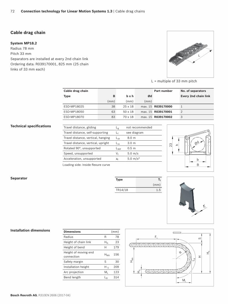
L
R
FL
ML
HS
L B
HS
HG
HM
A
b
23 h
B
Ød
TI
TI
H
H1
H2
72
Bosch Rexroth AG, R310EN 2606 (2017-04)
Connection technology for Linear Motion Systems 1.3 | Cable drag chains
Cable drag chain
System MP18.2 Radius 78 mmPitch 33 mmSeparators are installed at every 2nd chain linkOrdering data: R039170001, 825 mm (25 chain links of 33 mm each)
Cable drag chain Part number No. of separators
Type B b x h Ød Every 2nd chain link
(mm) (mm) (mm)
ESD-MP18025 38 25 x 18 max. 15 R039170000 1
ESD-MP18050 63 50 x 18 max. 15 R039170001 2
ESD-MP18070 83 70 x 18 max. 15 R039170002 3
Installation dimensions
Separator
Dimensions (mm)
Radius R 78
Height of chain link HG 23
Height of bend H 179
Height of moving end connection
HMA 156
Safety margin S 30
Installation height H S 209
Arc projection ML 123
Bend length LB 314
Travel distance, gliding Lg not recommended
Travel distance, self-supporting Lf see diagram
Travel distance, vertical, hanging Lvh 8.0 m
Travel distance, vertical, upright Lvs 3.0 m
Rotated 90°, unsupported L90f 0.5 m
Speed, unsupported Vf 5.0 m/s
Acceleration, unsupported af 5.0 m/s2
Type TI
(mm)
TR14/18 1.5
Loading side: Inside flexure curve
Technical specifications
L = multiple of 33 mm pitch

L
R
FL
ML
HS
V, H
SK
L B HS
K, S
V
HG
HM
A
TI
TI
H
H1
H2
b
36 h
B
Ød
7373
Bosch Rexroth AG, R310EN 2606 (2017-04)
Cable drag chains | Connection technology for Linear Motion Systems 1.3
Cable drag chain
System MP3000Radius 70 mmPitch 45 mmSeparators are installed at every 2nd chain link.Ordering data: R039170004, 990 mm (22 chain links of 45 mm each)
Installation dimensions
Separator
Loading side: Inside flexure curve
Technical specifications
Cable drag chain Part number No. of separators
Type B (mm) b x h (mm) Ød (mm) Every 2nd chain link
ESD-MP3002 55 37 x 26 max. 23 R039170003 1
ESD-MP3003 80 62 x 26 max. 23 R039170004 2
ESD-MP3005 119 101 x 26 max. 23 R039170005 3
Dimensions (mm)
Radius R 70
Height of chain link HG 35
Height of bend H 175
Height of moving end connection
HMA 140
Safety margin with bias SV 45
Installation height with bias HSV 220
Safety margin without bias SK 10
Installation height without bias HSK 185
Arc projection ML 133
Bend length LB 320
Travel distance, gliding Lg 60 m
Travel distance, self-supporting Lf see diagram
Travel distance, vertical, hanging Lvh 40 m
Travel distance, vertical, upright Lvs 3 m
Rotated 90°, unsupported L90f 0.7 m
Speed, gliding Vg 3 m/s
Speed, unsupported Vf 6 m/s
Acceleration, gliding ag 10 m/s2
Acceleration, unsupported af 15 m/s2
Type TI H H1 H2
(mm) (mm) (mm) (mm)
TR 3000 1.5 2.5 12.9 12.9

74
Bosch Rexroth AG, R310EN 2606 (2017-04)
Connection technology for Linear Motion Systems 1.3 | Cable drag chains
Chain bracket(included with the cable drag chain)
Scope of supply1 piece with bore, 1 piece with pivot pin screws and sliding blocks
The chain brackets must be fastened using the included screws. The cables or hoses must be fixed to the chain bracket’s integrated strain relief using cable binders.
Chain type Chain bracket A B C D E F G
(mm) (mm) (mm) (mm) (mm) (mm) (mm)
MP18025 KA/Z 18025 25.4 – 37 19 8.5 Ø 5.5 –
MP18050 KA/Z 18050 50.4 34 62 19 10.5 Ø 5.5 –
MP18070 KA/Z 18070 70.4 48 82 19 10.5 Ø 5.5 –
MP3002 KA/Z 3002 37.0 30 55 – 31.5 Ø 6.5 7.5
MP3003 KA/Z 3003 62.0 62 80 – 31.5 Ø 6.5 18.5
MP3005 KA/Z 3005 101.0 94 119 – 31.5 Ø 6.5 18.5
MP18050/18070
MP3000
MP18025

00 0,5 1,0 1,5 2,0 2,5 3,0
0,1
1
101
2
00 0,5 1,0 1,5 2,0 2,5 3,0
0,1
1
101
200 0,5 1,0 1,5 2,0 2,5 3,0
0,1
1
101
2
FLg
FLb
00 0,5 1,0 1,5 2,0 2,5 3,0
0,1
1
101
2
MP18.2
MP3000
L
RT
E
L/2 L/2
LK = + p · R + 2 · T + EL2
7575
Bosch Rexroth AG, R310EN 2606 (2017-04)
Cable drag chains | Connection technology for Linear Motion Systems 1.3
Technical data
Unsupported length
FLg:Ideal installation situation for high loads at the limit of the max. travel parameters. In this range the chain upper run is still biased, straight or has a max. sag of 10 – 50 mm depending on the type of chain.
FLb:Satisfactory installation position for many applications working in the lower to middle range of the max. travel parameters. Depending on the chain type, the sag of the chain upper run is > 10 – 50 mm but less than the max. sag.If the sag is greater than FLb, the arrangement is unsuitable and should be avoided. Please choose a more stable cable drag chain.
1 Load (kg/m)2 Self-supporting length (m)
Determining the chain lengthThe fixed point of the cable drag chain should be connected in the middle of the travel distance. This arrangement gives the shortest connection between the fixed point and the moving consumer and thus the most efficient chain length.
LK= Chain length (mm)
L = Travel distance (mm)
R = Radius (mm)
T = Pitch (mm)
E = Distance between entry point and middle of travel distance (mm)
MP18.2: ~ 1 m chain: 30 x 33 mm links
MP3000: ~ 1 m chain: 22 x 45 mm links

A
B
C
1,5
Ø10,4
90° N x 500
L (max. 4000)
DE50
1
2
500
ØF
D
EØF
76
Bosch Rexroth AG, R310EN 2606 (2017-04)
Connection technology for Linear Motion Systems 1.3 | Cable drag chains
Guide channels
For cable drag chainsThe guide channels are matched to the cable drag chains. For short travel distances they serve as a support for stack-ing the links and for long travel distances they also serves as guides. To minimize chain wear, stainless steel sheet was chosen as the material for the guide channels.The mounting holes for the chain bracket are already inte-grated in the guide channel.The guide channel has holes drilled at 500 mm intervals along the centerline for M5 countersunk screws. It comes complete with the necessary countersunk screws and sliding blocks.
Chain type Guide channel A B C D E F Part number (variable length)
(mm) (mm) (mm) (mm) (mm) (mm)
MP18025 Chain guide for MP18025 23 47 61 15 19 Ø 5.5 R039170006
MP18050 Chain guide for MP18050 23 72 86 34 34 Ø 5.5 R039170007
MP18070 Chain guide for MP18070 23 92 106 34 48 Ø 5.5 R039170008
MP3002 Chain guide for MP3002 35 70 84 12.5 25 Ø 6.6 R039170009
MP3003 Chain guide for MP3003 35 95 109 12.5 45 Ø 6.6 R039170010
MP3005 Chain guide for MP3005 35 134 148 12.5 85 Ø 6.6 R039170011
Version for chain type:1 MP180252 MP18050, MP18070, MP3002, MP3003, MP3005
L (max. 4000)

L1
8
12
40
Ø6,
6H13
619,5±0,2
25±0
,15
2
3
7777
Bosch Rexroth AG, R310EN 2606 (2017-04)
Cable drag chains | Connection technology for Linear Motion Systems 1.3
Attachment of cable drag chains
The following standardized interfaces were designed to facilitate connection of the cable drag chain or guide channel in a variety of ways. By combining these standard elements, it is possible to accommodate almost any desired connection configuration.
Cable drag chain node pointScope of supplyProfile (1x), socket head cap screws M6 (2x), sliding block M6 (2x), Screw DIN 7500 M5x25 (2x)
Profile Length Part number m(mm) (mm) Variable (kg) (kg/m)
12x40 200 R039170012 0.18
R039170013 0.90
Examples
Any standard small parts not used must be disposed of appropriately!
2 Screws M6x20, sliding blocks N8M6
3 Screws DIN7500 M5x25
1 For self-tapping screws M5
c Attachment of cable drag chains
c Attachment of cable drag chain with guide channel

21
78
Bosch Rexroth AG, R310EN 2606 (2017-04)
Connection technology for Linear Motion Systems 1.3 | Cable drag chains
Linear motion system node point
Scope of supplyClamping profile (1x), countersunk screws per DIN 7500 M5 (2x), set screws (4x)
1 Attachment to the connection plate
Linear motion system Profile nominal dimension
Part number
CKK/CKR 70 R039170014
90 R039170014
110 R039170015
145 R039170015
Examples
2 Attachment to the frame
Linear motion system Profile nominal dimension
Part number
CKK/CKR 70 R039170033
90 R039170014
110 R039170015
VKK 50 R039170033
70 R039170015
100 R039170015
MKK/MKR 40 R039170033

7979
Bosch Rexroth AG, R310EN 2606 (2017-04)
Cable drag chains | Connection technology for Linear Motion Systems 1.3
VKK node point
Scope of supplySplit clamp, screws (2x)
Examples
Part number m
(kg)
R039170019 0.12

80
Bosch Rexroth AG, R310EN 2606 (2017-04)
Connection technology for Linear Motion Systems 1.3 | Cable drag chains
Angle bracket node pointScope of supplyBracket (1x), countersunk screws M5 (2x)
Part number
R039170017
Angle node point
The threads in the end face are spaced so that the profile can be attached using the included screws without any further preparation.
Strut node point
Scope of supplyClamping profile (1x), socket head cap screws (2x), sliding blocks (2x), countersunk screws M5 per DIN 7500 (2x)
Strut profile Part number
60 R039170032
90 R039170016
Examples

8181
Bosch Rexroth AG, R310EN 2606 (2017-04)
Cable drag chains | Connection technology for Linear Motion Systems 1.3
Ordering examples
2x profiles R039170012
1x guide channel R039170010, 380 mm
1x cable drag chain R039170000,792 mm
1x profile R039170013, 250 mm1x clamping profile R0391700141x bracket R039170017
1x cable drag chain R039170004,990 mm
2x profiles R0391700122x clamping profiles R039170015
1x guide channel R039170006, 385 mm
2x profiles R0391700122x clamping profiles R039170015

82
Bosch Rexroth AG, R310EN 2606 (2017-04)
Connection technology for Linear Motion Systems 1.3 | Permissible loads
Easier to get results that fitTailor-made solutions just like that – with support all the way.
Faster route to your ideal applicationEffortless adaptation, even to future requirements – fast and flexible scalability.
More economical thanks to built-in efficiencyOptimizes processes from planning through to operation – with signifi-cant savings on resources.
Planning – up to 70% fasterEasyHandling tools help users right from the component selection stage – by proposing solutions with all the neces-sary information on parts lists, technical data and CAD drawings.
Installation – saves up to 60% on timeThanks to positive-locking interfaces, the mechanical com-ponents are perfectly aligned and accurately connected right away.
Start-up – reduces your effort by up to 90%With the smart start-up assistant EasyWizard, parameteriza-tion and configuration take no time at all. Your handling system will be ready to go in just a few clicks.
Production – more economical and more efficientRexroth enhances the system effectiveness still further with smart application tools: The drive controller software sends maintenance-related messages to the user based on operat-ing hours and travel to help schedule servicing at the right intervals. The result: longer life and reduced risk of failure.
Future developments – continuous improvementPrepare now for future market developments: One of the great features of EasyHandling systems is their openness. The flexibility of the mechanical and electrical components allows you to adapt quickly and efficiently to new produc-tion requirements.
EasyHandling –Easier. Faster. More Economical.EasyHandling –Easier. Faster. More Economical.

advanced
comfort
basic
EasyHandling
EasyHandling
EasyHandling
8383
Bosch Rexroth AG, R310EN 2606 (2017-04)
Permissible loads | Connection technology for Linear Motion Systems 1.3
EasyHandling – more than just a building systemThe modular system concept for perfect scalability
basic – made-to-measure mechanicsEasyHandling basic includes all mechatronic compo-nents for complete, custom single and multiaxis linear motion systems.All of the component interfaces are systematically stan-dardized, making it possible to combine them with ease. Practical tools and aids make selection and configura-tion even easier.
comfort – get off to a faster startEasyHandling comfort expands the basic component range by adding powerful servo drives with multiple protocol capability. The universal, smart control units are ideally suited for a variety of handling tasks. Unique: with the EasyWizard start-up assistant, linear motion systems are ready to use after entering just a few product-specific parameters.
advanced – controls for demanding requirementsWith its individually scalable, high-performance Motion Logic solution, EasyHandling advanced makes configuration and handling even easier. Predefined functions covering more than 90 percent of all handling applications eliminate the need for lengthy programming.

R310EN 2606 (2017-04)© Bosch Rexroth AG 2017Subject to change!
Bosch Rexroth AGErnst-Sachs-Straße 10097424 Schweinfurt, GermanyTel. +49 9721 937-0 Fax +49 9721 937-275www.boschrexroth.com
Find your local contact person here: www.boschrexroth.com/contact
The data specified above only serve to describe the product.Since our products undergo continuous further development, no statement regarding any particular quality or suitability for any particular use can be derived from this information. The information given does not release the user from the obligation of own judgment and verification. It must be remembered that our products are subject to a natural process of wear and aging.