connections catalog - gloenco.com · 33 2017 afglobal corporation. all rights resered. class 175...
TRANSCRIPT

CONNECTIONS CATALOG
AFGlobal’s offers premium products from trusted brands.


1 ©2017 AFGlobal Corporation. All rights reserved.
About AFGlobalAFGlobal Corporation is a privately-held Houston-based company with a global footprint across four continents. Our offerings
support the Oil and Gas, Petrochemical / Refining, General Industrial, Aerospace and Power Generation markets.
Through innovative design, specialized forging techniques, and versatility of equipment, AFGlobal is uniquely positioned
to meet our customers’ exacting requirements efficiently and economically. We offer a wide array of forged products
manufactured at several AFGlobal facilities across our global network. Our product offering ranges from commodity flanges
– both raw forgings and finished flange profiles – to highly engineered connectors and components for all major industries.
Our product brands – names like Coffer, TaperLok®, Texas Metal Works, and Forged Vessel Connections – are synonymous
with quality and reliability. We also offer everything from squared and contoured rings to large block forgings. Our forging
capabilities allow us to provide the correct solutions for your challenges.
Our testing and machining services are backed by ASME and ISO 9001 certifications, along with other industry standards as
required. We also feature advanced in-house heat treating capabilities, ensuring the highest quality standards throughout the
manufacturing process. As regulations become more stringent within our industries, customers have an escalating challenge
to satisfy these requirements. Our in-house engineering team enables AFGlobal to analyze, develop, and implement flexible
solutions to complex connection challenges.
Forging
— Open Die
— Closed Die
— Upsetting
— Hammers
— Seamless Ring Rolling
— Ring Stretching
Fabrication & Assembly
— Systems & Sub-Systems
— Components
Machining
— Rough & Finish Turning
— Rough & Finish Milling
— Drilling
Inspection
— Riser Inspection
— Compliant with EN 10204 3.1 inspection
— EN 10204 3.2 inspection available upon request
Heat Treating
— Quench and temper
— Anneal
— Normalize
— Stress Relieve
Testing
— A2LA accredited mechanical test lab, Certificate No 2162.01
— NDE (UT,LP, MP, RT)
— PMI
— Metallurgical testing
Welding
— Tubular
— Structural
— Clad Overlay & Inlay
— Electron Beam
— Brazing
Miscellaneous
— Shot Blasting
— Grinding
— Coating & Painting
Capabilities Overview

Table of Contents
About AFGlobal........................................................................................................................................1AFGlobal Flange General Information.................................................................................................4 & 5
ANSI B16.5 FLANGES
Class 150..........................................................................................................................................6 & 7Class 300..........................................................................................................................................8 & 9Class 400......................................................................................................................................10 & 11Class 600......................................................................................................................................12 & 13Class 900......................................................................................................................................14 & 15Class 1500....................................................................................................................................16 & 17Class 2500....................................................................................................................................18 & 19
API, INDUSTRY STANDARD AND AWWA FLANGES
Class 75 per API-605.....................................................................................................................20 & 21Class 75 per Industry Standard.......................................................................................................22 & 23Class 75 per Industry Standard.......................................................................................................24 & 25Class125 LW, AWWA C207 Class B&D..........................................................................................26 & 27Class 125 AWWA C207 Class E.....................................................................................................28 & 29Class 150 Welding Neck per B16.47 series A and B (MSS-SP44 and API-605)..............................30 & 31Class 150 Slip-On per MSS-SP-44.........................................................................................................32Class 175 Industry Standard..........................................................................................................33 & 34Class 250 Welding Neck, B16.1.............................................................................................................35Class 250 Slip-On, B16.1......................................................................................................................36Class 300 Welding Neck & Blind per B16.47 series A and B (MSS-SP44 and API-605)..................37& 38Class 300 Slip-On per MSS-SP-44........................................................................................................39Class 350 Welding Neck Industry Standard............................................................................................40Class 350 Slip-On Industry Standard.......................................................................................................41Class 400 B16.47 series A and B (MSS-SP-44 and API-605) .......................................................42 & 43Class 600 B16.47 series A and B (MSS-SP-44 and API-605)........................................................44 & 45Class 900 B16.47 series A and B (MSS-SP-44 and API-605)........................................................46 & 47
ORIFICE FLANGES
Class 300 Welding Neck, Slip-On & Threaded...............................................................................48 & 49Class 400 Welding Neck................................................................................................................50 & 51Class 600 Welding Neck................................................................................................................52 & 53Class 900 Welding Neck................................................................................................................54 & 55Class 1500 Welding Neck..............................................................................................................56 & 57Class 2500 Welding Neck..............................................................................................................58 & 59
2 ©2017 AFGlobal Corporation. All rights reserved.

Table of Contents
MISCELLANEOUS INFORMATION
Typical Facings for Steel Pipe Flanges – Drawings..................................................................................60Facing Dimensions for Ring Joints – Class 150 - Class 600...........................................................61 & 62Facing Dimensions for Ring Joints – Class 900 - Class 1500.........................................................63 & 64Facing Dimensions for Ring Joints – Class 2500....................................................................................65
FVC STANDARD AND VARIABLE BODY CONNECTIONS General Information........................................................................................................................66 - 68Class 150.......................................................................................................................................69 - 72Class 300.......................................................................................................................................73 - 76Class 400.......................................................................................................................................77 - 80Class 600.......................................................................................................................................81 - 84Class 900.......................................................................................................................................85 - 88Class 1500.....................................................................................................................................89 - 92Class 2500.....................................................................................................................................93 - 96General Notes for FVC Connections.......................................................................................................97
FVC STUDDING OUTLETS Class 150..............................................................................................................................................98Class 300..............................................................................................................................................99Class 600............................................................................................................................................100Class 900............................................................................................................................................101Class 1500..........................................................................................................................................102Class 2500..........................................................................................................................................103General Notes for FVC Studding Outlets.......................................................................................104-106FVC Technical Appendix..............................................................................................................107 - 127
3©2017 AFGlobal Corporation. All rights reserved.

4 ©2017 AFGlobal Corporation. All rights reserved.
Flange Types Face Types MFG. Standards
Specification Grade Symbol
Special Forgings:
Size Range:
Pressure Range:
Welding Neck
Slip-on
Blind
Threaded
Socket Weld
Lapped Joint
Expanding
Long Weld Neck
Studding Outlet
Solids & Special Bores
Specials per Drawings
ASTM A182
ASTM A182
ASTM A182
ASTM A182
ASTM A182
1 ¼% Chrome, ½% Moly
2 ¼% Chrome, 1% Moly
4-6% Chrome, ½% Moly
9% Chrome, 1% Moly
13% Chrome
F-11 Class 1, 2 & 3
F-22 Class 1 & 3
F-5 & F-5A
F-9
F-6A Class 1,2,3,& 4 (F410)
AFGlobal Flanges are available in the following alloy materials
Raised Face
Flat Face
Large Male & Female
Large Tongue & Groove
Small Tongue & Groove
Ring Joint
16-500 AARH and RMS
Specials per Drawings
ASTM
ASME
ANSI
MSS
API
AGA
AWWA
— Discs or Flat Rounds
— Blocks and Rectangles
— Round Bars
— Custom Shape Forgings
— Wyes, Laterals, Tees
Any Size Required
75 lb. through 2,500 lb.
Chromes

5 ©2017 AFGlobal Corporation. All rights reserved.
Stainless Steels
Carbon Steels
Other Types
Specification Grade Symbol
ASTM A182
ASTM A182
ASTM A182
ASTM A182
ASTM A182
ASTM A182
ASTM A182
ASTM A182
ASTM A182
ASTM A182
ASTM A182
ASTM A182
ASTM A182
ASTM A182
ASTM A182
ASTM A182
Stainless Steel
Stainless Steel
Stainless Steel
Stainless Steel
Stainless Steel
Stainless Steel
Stainless Steel
Stainless Steel
Stainless Steel
Stainless Steel
Stainless Steel
Stainless Steel
Stainless Steel
Stainless Steel
Stainless Steel
Stainless Steel
F-304
F-304H
F-304L
F-316
F-316H
F-316L
F-321
F-321H
F-347
F-347H
F-310
317
317-L
Duplex F-51 (2205)
F-44 (254-SMO)
F53 Super Duplex
ASTM A105N
ASTM A350
A694
A694
A694
A694
A694
Carbon
Low Temp
High-Yield Carbon
High-Yield Carbon
High-Yield Carbon
High-Yield Carbon
High-Yield Carbon
A105N
LF-2
F42
F52
F60
F65
F70
ASTM B564, B408
ASTM B425
ASTM B160
ASTM B160
ASTM B564, B446
ASTM B564, B166
ASTM B564, B164
ASTM B462, CB3
ASTM B691
ASTM B649
ASTM A564
C276
Nickel Alloy
Nickel Alloy
Nickel Alloy
Nickel Alloy
Nickel Alloy
Nickel Alloy
Nickel Alloy
Nickel Alloy
UNS-N08367
UNS-N08904
UNS-S17400
Hastelloy
Incoloy 800, H & HT
Incoloy 825
Nickel 200
Nickel 201
Inconel 625
Inconel 600
Monel 400
A-20, C-20
AL-6XN
904L
Grade 630 (17-4-PH)
INCO 25-6 MO
UNSN10276

6 ©2017 AFGlobal Corporation. All rights reserved.
NominalSize
3 1⁄2 3 7⁄8 4 1⁄4 4 5⁄8 5 6 7 7 1⁄2 8 1⁄2 9 10 11 13 1⁄2 16 19 21 23 1⁄2 25 27 1⁄2 29 1⁄2 32
OutsideDia.O
1 3⁄8 1 11⁄16
2 2 1⁄2 2 7⁄8 3 5⁄8 4 1⁄8 5 5 1⁄2 6 3⁄16
7 5⁄16
8 1⁄2 10 5⁄8 12 3⁄4 15 16 1⁄4 18 1⁄2 21 23 25 1⁄4 27 1⁄4
Thk.C
RaisedFaceDia.R
1⁄8 1⁄8 1⁄8
3⁄16
1⁄4 5⁄16
5⁄16
3⁄8 3⁄8 7⁄16
7⁄16
1⁄2 1⁄2 1⁄2 1⁄2 1⁄2 1⁄2 1⁄2 1⁄2 1⁄2 1⁄2
0.881.091.361.701.952.442.943.574.074.575.666.728.72
10.8812.8814.1416.1618.1820.2022.2224.25
WeldingNeck
SocketB1
Common Dimensions Bore
1⁄2 3⁄4 1 1 1⁄4 1 1⁄2 2 2 1⁄2 3 3 1⁄2 4 5 6 8 10 12 14 16 18 20 22 24
Length Thru Hub
FilletRadius
r
7⁄16
1⁄2 9⁄16
5⁄8
11⁄16
3⁄4 7⁄8 15⁄16
15⁄16
15⁄16
15⁄16
1 1 1⁄8 1 3⁄16
1 1⁄4 1 3⁄8 1 7⁄16
1 9⁄16
1 11⁄16
1 13⁄16
1 7⁄8
To b
e sp
ecifi
ed b
y pu
rcha
ser.
Slip-onB2
LapJoint
B3
.901.111.381.721.972.462.973.604.104.605.696.758.75
10.9212.9214.1816.1918.2020.2522.2524.25
WeldingNeck
Y1
1 7⁄8 2 1⁄16
2 3⁄16
2 1⁄4 2 7⁄16
2 1⁄2 2 3⁄4 2 3⁄4 2 13⁄16
3 3 1⁄2 3 1⁄2 4 4 4 1⁄2 5 5 5 1⁄2 5 11⁄16
5 7⁄8 6
Slip-onSocket
Y2
LapJoint
Y3
5⁄8 5⁄8 11⁄16
13⁄16
7⁄8 1 1 1⁄8 1 3⁄16
1 1⁄4 1 5⁄16
1 7⁄16
1 9⁄16
1 3⁄4 1 15⁄16
2 3⁄16
2 1⁄4 2 1⁄2 2 11⁄16
2 7⁄8 3 1⁄8 3 1⁄4
5⁄8 5⁄8 11⁄16
13⁄16
7⁄8 1 1 1⁄8 1 3⁄16
1 1⁄4 1 5⁄16
1 7⁄16
1 9⁄16
1 3⁄4 1 15⁄16
2 3⁄16
3 1⁄8 3 7⁄16
3 13⁄16
4 1⁄16
4 1⁄4 4 3⁄8
Class 150
ANSI B16.5
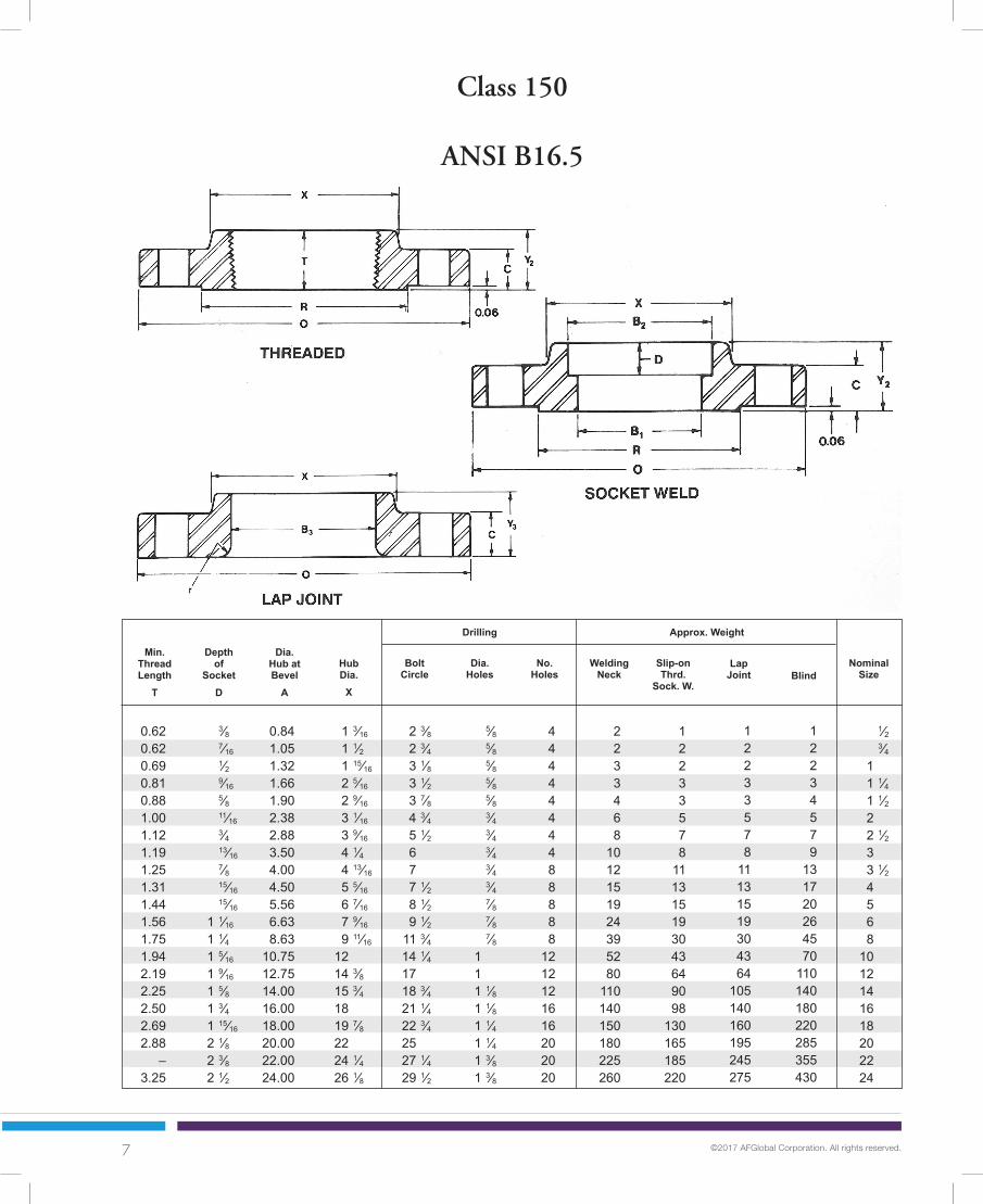
7 ©2017 AFGlobal Corporation. All rights reserved.
Min.
ThreadLength
T
0.620.620.690.810.881.001.121.191.251.311.441.561.751.942.192.252.502.692.88
–3.25
3⁄8 7⁄16 1⁄2 9⁄16 5⁄8 11⁄16 3⁄4 13⁄16 7⁄8 15⁄16
15⁄16
1 1⁄16
1 1⁄4 1 5⁄16
1 9⁄16
1 5⁄8 1 3⁄4 1 15⁄16
2 1⁄8 2 3⁄8 2 1⁄2
Depthof
SocketD
0.841.051.321.661.902.382.883.504.004.505.566.638.63
10.7512.7514.0016.0018.0020.0022.0024.00
1 3⁄16
1 1⁄2 1 15⁄16
2 5⁄16
2 9⁄16
3 1⁄16
3 9⁄16
4 1⁄4 4 13⁄16
5 5⁄16
6 7⁄16
7 9⁄16
9 11⁄16
12 14 3⁄8 15 3⁄4 18 19 7⁄8 22 24 1⁄4 26 1⁄8
Dia.Hub atBevel
A
HubDia.
X
2 3⁄8 2 3⁄4 3 1⁄8 3 1⁄2 3 7⁄8 4 3⁄4 5 1⁄2 6 7 7 1⁄2 8 1⁄2 9 1⁄2 11 3⁄4 14 1⁄4 17 18 3⁄4 21 1⁄4 22 3⁄4 25 27 1⁄4 29 1⁄2
5⁄8 5⁄8 5⁄8 5⁄8
5⁄8 3⁄4 3⁄4 3⁄4 3⁄4 3⁄4 7⁄8 7⁄8 7⁄8 1 1 1 1⁄8 1 1⁄8 1 1⁄4 1 1⁄4 1 3⁄8 1 3⁄8
4444444488888
1212121616202020
2233468
1012151924395280
110140150180225260
12233578
111315193043649098
130165185220
12233578
11131519304364
105140160195245275
12234579
131720264570
110140180220285355430
1⁄2 3⁄4 1 1 1⁄4 1 1⁄2 2 2 1⁄2 3 3 1⁄2 4 5 6 8 10 12 14 16 18 20 22 24
BoltCircle
Dia.Holes
No.Holes
WeldingNeck
Slip-onThrd.
Sock. W.
LapJoint Blind
NominalSize
Drilling Approx. Weight
Class 150
ANSI B16.5

8 ©2017 AFGlobal Corporation. All rights reserved.
NominalSize
3 3⁄4 4 5⁄8 4 7⁄8 5 1⁄4 6 1⁄8 6 1⁄2 7 1⁄2 8 1⁄4 9 10 11 12 1⁄2 15 17 1⁄2 20 1⁄2 23 25 1⁄2 28 30 1⁄2 33 36
OutsideDia.O
1 3⁄8 1 11⁄16
2 2 1⁄2 2 7⁄8 3 5⁄8 4 1⁄8 5 5 1⁄2 6 3⁄16
7 5⁄16
8 1⁄2 10 5⁄8 12 3⁄4 15 16 1⁄4 18 1⁄2 21 23 25 1⁄4 27 1⁄4
Thk.C
RaisedFaceDia.R
1⁄8 1⁄8 1⁄8
3⁄16
1⁄4 5⁄16
5⁄16
3⁄8 3⁄8 7⁄16
7⁄16
1⁄2 1⁄2 1⁄2 1⁄2 1⁄2 1⁄2 1⁄2 1⁄2 1⁄2 1⁄2
0.881.091.361.701.952.442.943.574.074.575.666.728.72
10.8812.8814.1416.1618.1820.2022.2224.25
WeldingNeck
SocketB1
Common Dimensions Bore
1⁄2 3⁄4 1 1 1⁄4 1 1⁄2 2 2 1⁄2 3 3 1⁄2 4 5 6 8 10 12 14 16 18 20 22 24
Length Thru Hub
FilletRadius
r
9⁄16
5⁄8 11⁄16
3⁄4
13⁄16
7⁄8 1 1 1⁄8 1 3⁄16
1 1⁄4 1 3⁄8 1 7⁄16
1 5⁄8 1 7⁄8 2 2 1⁄8 2 1⁄4 2 3⁄8 2 1⁄2 2 5⁄8 2 3⁄4
To b
e sp
ecifi
ed b
y pu
rcha
ser.
Slip-onB2
LapJoint
B3
.901.111.381.721.972.462.973.604.104.605.696.758.75
10.9212.9214.1816.1918.2020.2522.2524.25
WeldingNeck
Y1
2 1⁄16
2 1⁄4 2 7⁄16
2 9⁄16
2 11⁄16
2 3⁄4 3 3 1⁄8 3 3⁄16
3 3⁄8 3 7⁄8 3 7⁄8 4 3⁄8 4 5⁄8 5 1⁄8 5 5⁄4 5 3⁄4 6 1⁄4 6 3⁄8 6 1⁄8 6 5⁄8
Slip-onSocket
Y2
LapJoint
Y3
7⁄8 1 1 1⁄16
1 1⁄16
1 3⁄16
1 5⁄16
1 1⁄2 1 11⁄16
1 3⁄4 1 7⁄8 2 2 1⁄16
2 7⁄16
2 5⁄8 2 7⁄8 3 3 1⁄4 3 1⁄2 3 3⁄4 4 4 3⁄16
7⁄8 1 1 1⁄16
1 1⁄16
1 3⁄16
1 5⁄16
1 1⁄2 1 11⁄16
1 3⁄4 1 7⁄8 2 2 1⁄16
2 7⁄16
3 3⁄4 4 4 3⁄8 4 3⁄4 5 1⁄8 5 1⁄2 5 3⁄4 6
Class 300
ANSI B16.5

9 ©2017 AFGlobal Corporation. All rights reserved.
Min.
ThreadLength
T
Depthof
SocketD
Dia.Hub atBevel
A
HubDia.
X
2 5⁄8 3 1⁄4 3 1⁄2 3 7⁄8 4 1⁄2 5 5 7⁄8 6 5⁄8 7 1⁄4 7 7⁄8 9 1⁄4 10 5⁄8 13 15 1⁄4 17 3⁄4 20 1⁄4 22 1⁄2 24 3⁄4 27 29 1⁄4 32
5⁄8 3⁄4 3⁄4 3⁄4 7⁄8 3⁄4 7⁄8 7⁄8 7⁄8 7⁄8 7⁄8 7⁄8 1 1 1⁄8 1 1⁄4 1 1⁄4 1 3⁄8 1 3⁄8 1 3⁄8 1 5⁄8 1 5⁄8
44444888888
12121616202024242424
234579
1215182532426791
140180250320400465580
233467
1013172228395881
115165190250315370475
233467
1013172228395891
140190250295370435550
233468
12162127355081
124185250295395505640790
1⁄2 3⁄4 1 1 1⁄4 1 1⁄2 2 2 1⁄2 3 3 1⁄2 4 5 6 8 10 12 14 16 18 20 22 24
BoltCircle
Dia.Holes
No.Holes
WeldingNeck
Slip-onThrd.
Sock. W.
LapJoint Blind
NominalSize
Drilling Approx. Weight
0.630.630.690.810.881.131.251.251.441.441.691.812.002.192.382.502.692.752.883.133.25
0.841.051.321.661.902.382.883.504.004.505.566.638.63
10.7512.7514.0016.0018.0020.0022.0024.00
1 1⁄2 1 7⁄8 2 1⁄8 2 1⁄2 2 3⁄4 3 5⁄16
3 15⁄16
4 5⁄8 5 1⁄4 5 3⁄4 7 8 1⁄8 10 1⁄4 12 5⁄8 14 3⁄4 16 3⁄4 19 21 23 1⁄8 25 1⁄4 27 5⁄8
Class 300
ANSI B16.5
.38
.44
.50
.56
.63
.69
.75
.81
.88
.94———————————

10 ©2017 AFGlobal Corporation. All rights reserved.
NominalSize
10 11 12 1⁄2 15 17 1⁄2 20 1⁄2 23 25 1⁄2 28 30 1⁄2 33 36
OutsideDia.O
6 3⁄16
7 5⁄16
8 1⁄2 10 5⁄8 12 3⁄4 15 16 1⁄4 18 1⁄2 21 23 25 1⁄4 27 1⁄4
Thk.C
RaisedFaceDia.R
7⁄16
7⁄16
1⁄2 1⁄2 1⁄2 1⁄2 1⁄2 1⁄2 1⁄2 1⁄2 1⁄2 1⁄2
4.575.666.728.72
10.8812.8814.1416.1618.1820.2022.2224.25
WeldingNeck
SocketB1
Common Dimensions Bore
4 5 6 8 10 12 14 16 18 20 22 24
Length Thru Hub
FilletRadius
r
1 3⁄8 1 1⁄2 1 5⁄8 1 7⁄8 2 1⁄8 2 1⁄4 2 3⁄8 2 1⁄2 2 5⁄8 2 3⁄4 2 7⁄8 3
To b
e sp
ecifi
ed b
y pu
rcha
ser.
Slip-onB2
LapJoint
B3
4.605.696.758.75
10.9212.9214.1816.1918.2020.2522.2524.25
WeldingNeck
Y1
3 1⁄2 4 4 1⁄16
4 5⁄8 4 7⁄8 5 3⁄8 5 7⁄8 6 6 1⁄2 6 5⁄8 6 3⁄4 6 7⁄8
Slip-onSocket
Y2
LapJoint
Y3
2 2 1⁄8 2 1⁄4 2 11⁄16
2 7⁄8 3 1⁄8 3 5⁄16
3 11⁄16
3 7⁄8 4 4 1⁄4 4 1⁄2
2 2 1⁄8 2 1⁄4 2 11⁄16
4 4 1⁄4 4 5⁄8 5 5 3⁄8 5 3⁄4 6 6 1⁄4
SIZES 1⁄2" THRU 3 1⁄2"
Thickness and length do not include 1⁄4" raised face.
Class 400
ANSI B16.5

11 ©2017 AFGlobal Corporation. All rights reserved.
Min.
ThreadLength
T
Dia.Hub atBevel
A
HubDia.
X
7 7⁄8 9 1⁄4 10 5⁄8 13 15 1⁄4 17 3⁄4 20 1⁄4 22 1⁄2 24 3⁄4 27 29 1⁄4 32
1 1 1 1 1⁄8 1 1⁄4 1 3⁄8 1 3⁄8 1 1⁄2 1 1⁄2 1 5⁄8 1 3⁄4 1 7⁄8
88
12121616202024242424
35435789
125175230295350425505620
2631446791
130180235285345405510
25294264
110150205260315385455570
334461
100155225290370455587720890
4 5 6 8 10 12 14 16 18 20 22 24
BoltCircle
Dia.Holes
No.Holes
WeldingNeck
Slip-onThrd.
Sock. W.
LapJoint Blind
NominalSize
Drilling Approx. Weight
1.441.691.812.002.192.382.502.692.752.88
—3.25
4.505.566.638.63
10.7512.7514.0016.0018.0020.0022.0024.00
5 3⁄4 7 8 1⁄8 10 1⁄4 12 5⁄8 14 3⁄4 16 3⁄4 19 21 23 1⁄8 25 1⁄4 27 5⁄8
ARE IDENTICAL WITH CLASS 600
See 300 Class dimensions for dimensions “Q” and “D”.
Class 400
ANSI B16.5
12 ©2017 AFGlobal Corporation. All rights reserved.
NominalSize
3 3⁄4 4 5⁄8 4 7⁄8 5 1⁄4 6 1⁄8 6 1⁄2 7 1⁄2 8 1⁄4 9 10 3⁄4 13 14 16 1⁄2 20 22 23 3⁄4 27 29 1⁄4 32 34 1⁄4 37
OutsideDia.O
1 3⁄8 1 11⁄16
2 2 1⁄2 2 7⁄8 3 5⁄8 4 1⁄8 5 5 1⁄2 6 3⁄16
7 5⁄16
8 1⁄2 10 5⁄8 12 3⁄4 15 16 1⁄4 18 1⁄2 21 23 25 1⁄4 27 1⁄4
Thk.C
RaisedFaceDia.R
1⁄8 1⁄8 1⁄8
3⁄16
1⁄4 5⁄16
5⁄16
3⁄8 3⁄8 7⁄16
7⁄16
1⁄2 1⁄2 1⁄2 1⁄2 1⁄2 1⁄2 1⁄2 1⁄2 1⁄2 1⁄2
0.881.091.361.701.952.442.943.574.074.575.666.728.72
10.8812.8814.1416.1618.1820.2022.2224.25
WeldingNeck
SocketB1
Common Dimensions Bore
1⁄2 3⁄4 1 1 1⁄4 1 1⁄2 2 2 1⁄2 3 3 1⁄2 4 5 6 8 10 12 14 16 18 20 22 24
Length Thru Hub
FilletRadius
r
9⁄16
5⁄8 11⁄16
13⁄16
7⁄8 1 1 1⁄8 1 1⁄4 1 3⁄8 1 1⁄2 1 3⁄4 1 7⁄8 2 3⁄16
2 1⁄2 2 5⁄8 2 3⁄4 3 3 1⁄4 3 1⁄2 3 3⁄4 4
To b
e sp
ecifi
ed b
y pu
rcha
ser.
Slip-onB2
LapJoint
B3
.901.111.381.721.972.462.973.604.104.605.696.758.75
10.9212.9214.1816.1918.2020.2522.2524.25
WeldingNeck
Y1
2 1⁄16
2 1⁄4 2 7⁄16
2 5⁄8 2 3⁄4 2 7⁄8 3 1⁄8 3 1⁄4 3 3⁄8 4 4 1⁄2 4 5⁄8 5 1⁄4 6 6 1⁄8 6 1⁄2 7 7 1⁄4 7 1⁄2 7 3⁄4 8
Slip-onSocket
Y2
LapJoint
Y3
7⁄8 1 1 1⁄16
1 1⁄8 1 1⁄14
1 7⁄16
1 5⁄8 1 13⁄16
1 15⁄16
2 1⁄8 2 3⁄8 2 5⁄8 3 3 3⁄8 3 5⁄8 3 11⁄16
4 3⁄16
4 5⁄8 5 5 1⁄4 5 1⁄2
7⁄8 1 1 1⁄16
1 1⁄8 1 1⁄4 1 7⁄16
1 5⁄8 1 13⁄16
1 15⁄16
2 1⁄8 2 3⁄8 2 5⁄8 3 4 3⁄8 4 5⁄8 5 5 1⁄2 6 6 1⁄2 6 7⁄8 7 1⁄4
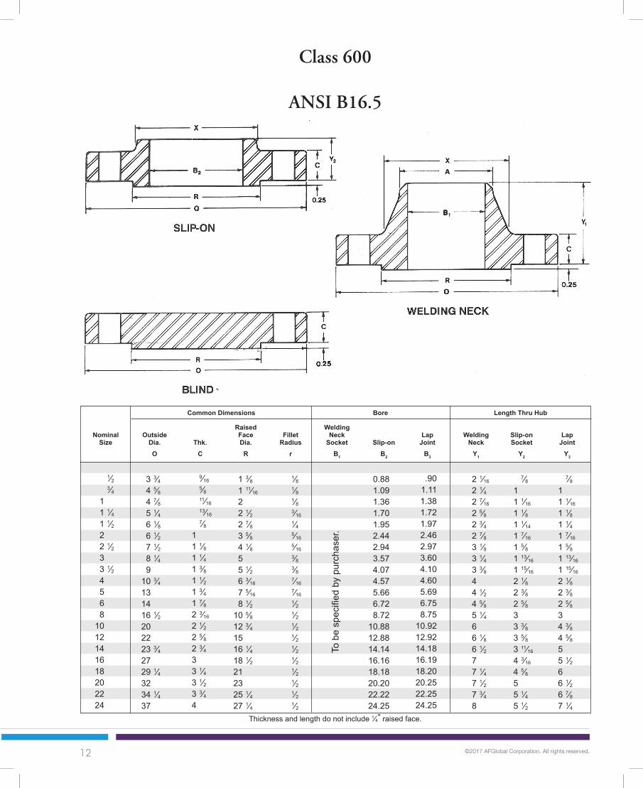
Class 600
ANSI B16.5
Thickness and length do not include 1⁄4" raised face.

13 ©2017 AFGlobal Corporation. All rights reserved.
Min.
ThreadLength
T
Depthof
SocketD
Dia.Hub atBevel
A
HubDia.
X
2 5⁄8 3 1⁄4 3 1⁄2 3 7⁄8 4 1⁄2 5 5 7⁄8 6 5⁄8 7 1⁄4 8 1⁄2 10 1⁄2 11 1⁄2 13 3⁄4 17 19 1⁄4 20 3⁄4 23 3⁄4 25 3⁄4 28 1⁄2 30 5⁄8 33
5⁄8 3⁄4 3⁄4 3⁄4 7⁄8 3⁄4 7⁄8 7⁄8 1 1 1 1⁄8 1 1⁄8 1 1⁄4 1 3⁄8 1 3⁄8 1 1⁄2 1 5⁄8 1 3⁄4 1 3⁄4 1 7⁄8 2
44444888888
12121620202020242424
24468
12182326426881
120190225280390475590720830
234579
131621376380
115170200230330400510590730
234579
121520366178
110170200250365435570670810
23458
10152029416886
140230295355495630810
10001250
1⁄2 3⁄4 1 1 1⁄4 1 1⁄2 2 2 1⁄2 3 3 1⁄2 4 5 6 8 10 12 14 16 18 20 22 24
BoltCircle
Dia.Holes
No.Holes
WeldingNeck
Slip-onThrd.
Sock. W.
LapJoint Blind
NominalSize
Drilling Approx. Weight
0.630.630.690.810.881.131.251.381.561.631.882.002.252.562.752.883.063.133.25
—3.63
0.841.051.321.661.902.382.883.504.004.505.566.638.63
10.7512.7514.0016.0018.0020.0022.0024.00
1 1⁄2 1 7⁄8 2 1⁄8 2 1⁄2 2 3⁄4 3 5⁄16
3 15⁄16
4 5⁄8 5 1⁄4 6 7 7⁄16
8 3⁄4 10 3⁄4 13 1⁄2 15 3⁄4 17 19 1⁄2 21 1⁄2 24 26 1⁄4 28 1⁄4
3⁄8 7⁄16 1⁄2 9⁄16 5⁄8 11⁄16 3⁄4 13⁄16 7⁄8 15⁄16
15⁄16
1 1⁄16
1 1⁄4 1 5⁄16
1 9⁄16
1 5⁄8 1 3⁄4 1 15⁄16
2 1⁄8 2 3⁄8 2 1⁄2
Class 600
ANSI B16.5
See 300 Class dimensions for dimensions “Q” and “D”.

14 ©2017 AFGlobal Corporation. All rights reserved.
NominalSize
9 1⁄2 11 1⁄2 13 3⁄4 15 18 1⁄2 21 1⁄2 24 25 1⁄4 27 3⁄4 31 33 3⁄4 41
OutsideDia.O
5 6 3⁄16
7 5⁄16
8 1⁄2 10 5⁄8 12 3⁄4 15 16 1⁄4 18 1⁄2 21 23 27 1⁄4
Thk.C
RaisedFaceDia.R
3⁄8 7⁄16
7⁄16
1⁄2 1⁄2 1⁄2 1⁄2 1⁄2 1⁄2 1⁄2 1⁄2 1⁄2
3.574.575.666.728.72
10.8812.8814.1416.1618.1820.2024.25
WeldingNeck
SocketB1
Common Dimensions Bore
3 4 5 6 8 10 12 14 16 18 20 24
Length Thru Hub
FilletRadius
r
1 1⁄2 1 3⁄4 2 2 3⁄16
2 1⁄2 2 3⁄4 3 1⁄8 3 3⁄8 3 1⁄2 4 4 1⁄4 5 1⁄2
To b
e sp
ecifi
ed b
y pu
rcha
ser.
Slip-onB2
LapJoint
B3
3.604.605.696.758.75
10.9212.9214.1816.1918.2020.2524.25
WeldingNeck
Y1
4 4 1⁄2 5 5 1⁄2 6 3⁄8 7 1⁄4 7 7⁄8 8 3⁄8 8 1⁄2 9 9 3⁄4 11 1⁄2
Slip-onSocket
Y2
LapJoint
Y3
2 1⁄8 2 3⁄4 3 1⁄8 3 3⁄8 4 4 1⁄4 4 5⁄8 5 1⁄8 5 1⁄4 6 6 1⁄4 8
SIZES 1⁄2" THRU 2 1⁄2" ARE
Thickness and length do not include 1⁄4" raised face.
2 1⁄8 2 3⁄4 3 1⁄8 3 3⁄8 4 1⁄2 5 5 5⁄8 6 1⁄8 6 1⁄2 7 1⁄2 8 1⁄4 10 1⁄2
Class 900
ANSI B16.5

15 ©2017 AFGlobal Corporation. All rights reserved.
Min.ThreadLength
T
Dia.Hub atBevel
A
HubDia.
X
7 1⁄2 9 1⁄4 11 12 1⁄2 15 1⁄2 18 1⁄2 21 22 24 1⁄4 27 29 1⁄2 35 1⁄2
1 1 1⁄4 1 3⁄8 1 1⁄4 1 1⁄2 1 1⁄2 1 1⁄2 1 5⁄8 1 3⁄4 2 2 1⁄8 2 5⁄8
888
121216202020202020
315386
110175260325400495680830
1500
265383
110170245325400425600730
1400
255181
105190275370415465650810
1550
295487
115200290415520600850
10752025
3 4 5 6 8 10 12 14 16 18 20 24
BoltCircle
Dia.Holes
No.Holes
WeldingNeck
Slip-onThrd.
Sock. W.
LapJoint Blind
NominalSize
Drilling Approx. Weight
1.631.882.132.252.502.813.003.253.383.503.634.00
3.504.505.566.638.63
10.7512.7514.0016.0018.0020.0024.00
5 6 1⁄4 7 1⁄2 9 1⁄4 11 3⁄4 14 1⁄2 16 1⁄2 17 20 22 1⁄4 24 1⁄2 29 1⁄2
ARE IDENTICAL WITH CLASS 1500
See 300 Class dimensions for dimensions “Q” and “D”.
Class 900
ANSI B16.5
16 ©2017 AFGlobal Corporation. All rights reserved.
NominalSize
4 3⁄4 5 1⁄8 5 7⁄8 6 1⁄4 7 8 1⁄2 9 5⁄8 10 1⁄2 12 1⁄4 14 3⁄4 15 1⁄2 19 23 26 1⁄2 29 1⁄2 32 1⁄2 36 38 3⁄4 46
OutsideDia.O
1 3⁄8 1 11⁄16
2 2 1⁄2 2 7⁄8 3 5⁄8 4 1⁄8 5 6 3⁄16
7 5⁄16
8 1⁄2 10 5⁄8 12 3⁄4 15 16 1⁄4 18 1⁄2 21 23 27 1⁄4
Thk.C
RaisedFaceDia.R
1⁄8 1⁄8 1⁄8
3⁄16
1⁄4 5⁄16
5⁄16
3⁄8 7⁄16
7⁄16
1⁄2 1⁄2 1⁄2 1⁄2 1⁄2 1⁄2 1⁄2 1⁄2 1⁄2
0.881.091.361.701.952.442.943.574.575.666.728.72
10.8812.8814.1416.1618.1820.2024.25
WeldingNeck
SocketB1
Common Dimensions Bore
1⁄2 3⁄4 1 1 1⁄4 1 1⁄2 2 2 1⁄2 3 4 5 6 8 10 12 14 16 18 20 24
Length Thru Hub
FilletRadius
r
7⁄8 1 1 1⁄8 1 1⁄8 1 1⁄4 1 1⁄2 1 5⁄8 1 7⁄8 2 1⁄8 2 7⁄8 3 1⁄4 3 5⁄8 4 1⁄4 4 7⁄8 5 1⁄4 5 3⁄4 6 3⁄8 7 8
To b
e sp
ecifi
ed b
y pu
rcha
ser.
Slip-onB2
LapJoint
B3
.901.111.381.721.972.462.973.604.605.696.758.75
10.9212.9214.1816.1918.2020.2524.25
WeldingNeck
Y1
2 3⁄8 2 3⁄4 2 7⁄8 2 7⁄8 3 1⁄4 4 4 1⁄8 4 5⁄8 4 7⁄8 6 1⁄8 6 3⁄4 8 3⁄8 10 11 1⁄8 11 3⁄4 12 1⁄4 12 7⁄8 14 16
Slip-onSocket
Y2
LapJoint
Y3
1 1⁄4 1 3⁄8 1 5⁄8 1 5⁄8 1 3⁄4 2 1⁄4 2 1⁄2 2 7⁄8 3 9⁄16
4 1⁄8 4 11⁄16
5 5⁄8 6 1⁄4 7 1⁄8 — — — — —
1 1⁄4 1 3⁄8 1 5⁄8 1 5⁄8 1 3⁄4 2 1⁄4 2 1⁄2 2 7⁄8 3 9⁄16
4 1⁄8 4 11⁄16
5 5⁄8 7 8 5⁄8 9 1⁄2 10 1⁄4 10 7⁄8 11 1⁄2 13
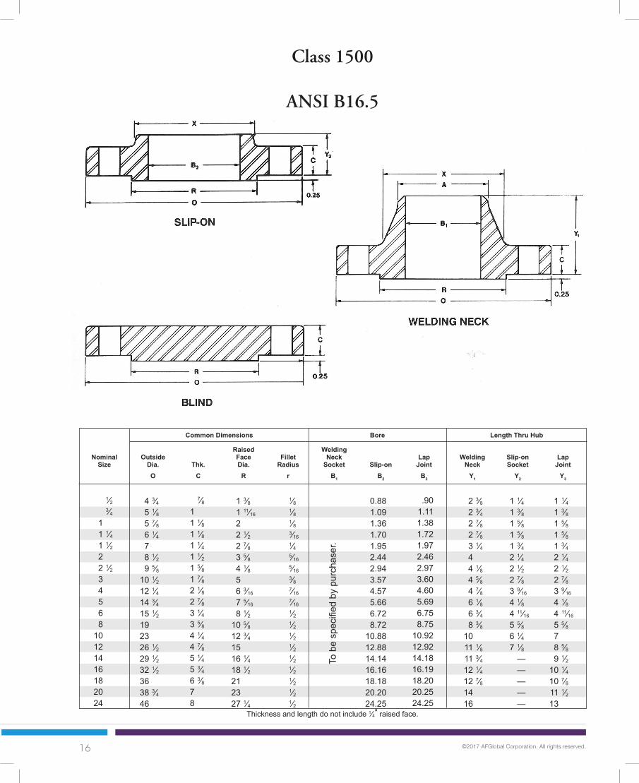
Class 1500
ANSI B16.5
Thickness and length do not include 1⁄4" raised face.

17 ©2017 AFGlobal Corporation. All rights reserved.
Min.
ThreadLength
T
Depthof
SocketD
Dia.Hub atBevel
A
HubDia.
X
3 1⁄4 3 1⁄2 4 4 3⁄8 4 7⁄8 6 1⁄2 7 1⁄2 8 9 1⁄2 11 1⁄2 12 1⁄2 15 1⁄2 19 22 1⁄2 25 27 3⁄4 30 1⁄2 32 3⁄4 39
7⁄8 7⁄8 1 1 1 1⁄8 1 1 1⁄8 1 1⁄4 1 3⁄8 1 5⁄8 1 1⁄2 1 3⁄4 2 2 1⁄8 2 3⁄8 2 5⁄8 2 7⁄8 3 1⁄8 3 5⁄8
4444488888
121212161616161616
569
101325364873
130165275455690940
1250162520503325
4589
1225364873
130165260435580
—————
4589
1225354775
140170285485630890
1150147517752825
4689
1325354873
140160300510690975
1300175022253625
1⁄2 3⁄4 1 1 1⁄4 1 1⁄2 2 2 1⁄2 3 4 5 6 8 10 12 14 16 18 20 24
BoltCircle
Dia.Holes
No.Holes
WeldingNeck
Slip-onThreaded
LapJoint Blind
NominalSize
Drilling Approx. Weight
0.881.001.131.191.251.501.882.002.252.502.753.003.313.36
—————
0.841.051.321.661.902.382.883.504.505.566.638.63
10.7512.7514.0016.0018.0020.0024.00
1 1⁄2 1 3⁄4 2 1⁄16
2 1⁄2 2 3⁄4 4 1⁄8 4 7⁄8 5 1⁄4 6 3⁄8 7 3⁄4 9 11 1⁄2 14 1⁄2 17 3⁄4 19 1⁄2 21 3⁄4 23 1⁄2 25 1⁄4 30
3⁄8 7⁄16 1⁄2 9⁄16 5⁄8 11⁄16 3⁄4 13⁄16 15⁄16
15⁄16
1 1⁄16
1 1⁄4 1 5⁄16
1 9⁄16
1 5⁄8 1 3⁄4 1 15⁄16
2 1⁄8 2 1⁄2
See 300 Class dimensions for dimensions “Q” and “D”.
Class 1500
ANSI B16.5

18 ©2017 AFGlobal Corporation. All rights reserved.
NominalSize
5 1⁄4 5 1⁄2 6 1⁄4 7 1⁄4 8 9 1⁄4 10 1⁄2 12 14 16 1⁄2 19 21 3⁄4 26 1⁄2 30
OutsideDia.O
1 3⁄8 1 11⁄16
2 2 1⁄2 2 7⁄8 3 5⁄8 4 1⁄8 5 6 3⁄16
7 5⁄16
8 1⁄2 10 5⁄8 12 3⁄4 15
Thk.C
RaisedFaceDia.R
1⁄8 1⁄8 1⁄8
3⁄16
1⁄4 5⁄16
5⁄16
3⁄8 7⁄16
7⁄16
1⁄2 1⁄2 1⁄2 1⁄2
0.881.091.361.701.952.442.943.574.575.666.728.72
10.8812.88
WeldingNeck
SocketB1
Common Dimensions Bore
1⁄2 3⁄4 1 1 1⁄4 1 1⁄2 2 2 1⁄2 3 4 5 6 8 10 12
Length Thru Hub
FilletRadius
r
1 3⁄16
1 1⁄4 1 3⁄8 1 1⁄2 1 3⁄4 2 2 1⁄4 2 5⁄8 3 3 5⁄8 4 1⁄4 5 6 1⁄2 7 1⁄4
To b
e sp
ecifi
ed b
y pu
rcha
ser.
Slip-onB2
LapJoint
B3
.901.111.381.721.972.462.973.604.605.696.758.75
10.9212.92
WeldingNeck
Y1
2 7⁄8 3 1⁄8 3 1⁄2 3 3⁄4 4 3⁄8 5 5 5⁄8 6 5⁄8 7 1⁄2 9 10 3⁄4 12 1⁄2 16 1⁄2 18 1⁄4
Slip-onY2
LapJoint
Y3
1 9⁄16
1 11⁄16
1 7⁄8 2 1⁄16
2 3⁄8 2 3⁄4 3 1⁄8 3 5⁄8 4 1⁄4 5 1⁄8 6 7 9 10
1 9⁄16
1 11⁄16
1 7⁄8 2 1⁄16
2 3⁄8 2 3⁄4 3 1⁄8 3 5⁄8 4 1⁄4 5 1⁄8 6 7 9 10
Class 2500 Slip-Ons are not included in ANSI B16.5 specifications.Thickness and length do not include 1⁄4” raised face.
Class 2500
ANSI B16.5

19 ©2017 AFGlobal Corporation. All rights reserved.
Min.
ThreadLength
T
Dia.Hub atBevel
A
HubDia.
X
3 1⁄2 3 3⁄4 4 1⁄4 5 1⁄8 5 3⁄4 6 3⁄4 7 3⁄4 9 10 3⁄4 12 3⁄4 14 1⁄2 17 1⁄4 21 1⁄4 24 3⁄8
7⁄8 7⁄8 1 1 1⁄8 1 1⁄4 1 1⁄8 1 1⁄4 1 3⁄8 1 5⁄8 1 7⁄8 2 1⁄8 2 1⁄8 2 5⁄8 2 7⁄8
44444888888
121212
78
121725425294
145245380580
10751525
78
111622385583
125210325485930
1100
78
111723395686
135225345530
10251300
1⁄2 3⁄4 1 1 1⁄4 1 1⁄2 2 2 1⁄2 3 4 5 6 8 10 12
BoltCircle
Dia.Holes
No.Holes
WeldingNeck
Slip-onThreaded
LapJoint Blind
NominalSize
Drilling Approx. Weight
1.131.251.381.501.752.002.252.502.753.003.253.754.254.75
0.841.051.321.661.902.382.883.504.505.566.638.63
10.7512.75
1 11⁄16
2 2 1⁄4 2 7⁄8 3 1⁄8 3 3⁄4 4 1⁄2 5 1⁄4 6 1⁄2 8 9 1⁄4 12 14 3⁄4 17 3⁄8
See 300 Class dimensions for dimensions “Q” and “D”.
78
111622375380
120205315470900
1100
Class 2500
ANSI B16.5

20 ©2017 AFGlobal Corporation. All rights reserved.
NominalSize
30 32 34 36 38 40 11⁄16
42 11⁄16
44 11⁄16
46 11⁄16
49 1⁄4 51 1⁄4 53 1⁄4 55 1⁄4 57 3⁄8 59 3⁄8 62 64 66
OutsideDia.O
1 5⁄16
1 5⁄16
1 3⁄8 1 31⁄64
1 1⁄2 1 5⁄8 1 11⁄16
1 3⁄4 1 7⁄8 2 2 1⁄16
2 1⁄8 2 1⁄4 2 5⁄16
2 3⁄8 2 1⁄2 2 9⁄16
2 5⁄8
WeldingNeck Blind
3⁄8 3⁄8 3⁄8 3⁄8 1⁄2 1⁄2 1⁄2 1⁄2 1⁄2 1⁄2 1⁄2 1⁄2 1⁄2 1⁄2 5⁄8 5⁄8 5⁄8 5⁄8
ThicknessC
FilletRadius
r
1 5⁄16
1 5⁄16
1 5⁄16
1 3⁄8 1 3⁄8 1 7⁄16
1 1⁄2 1 1⁄2 1 9⁄16
1 11⁄16
1 3⁄4 1 13⁄16
1 7⁄8 1 7⁄8 1 15⁄16
2 2 1⁄16
2 3⁄16
To b
e sp
ecifi
ed b
y pu
rcha
ser.
BoreB
LengthThruHub
Y
Dia.Hub atBevel
A
HubDia.
X
26 5⁄8 28 5⁄8 30 5⁄8 32 5⁄8 34 5⁄8 36 13⁄16
38 13⁄16
40 13⁄16
42 13⁄16
44 7⁄8 46 7⁄8 48 7⁄8 50 15⁄16
52 15⁄16
55 57 1⁄8 59 1⁄8 61 1⁄8
27 3⁄4 29 3⁄4 31 3⁄4 33 3⁄4 35 3⁄4 38 40 42 44 46 1⁄2 48 1⁄4 50 1⁄4 52 1⁄4 54 1⁄4 56 1⁄4 58 1⁄2 60 1⁄2 62 1⁄2
RaisedFaceDia.R
262830323436384042444648505254565860
2 5⁄16
2 7⁄16
2 9⁄16
2 3⁄4 2 7⁄8 3 3⁄8 3 1⁄2 3 5⁄8 3 3⁄4 4 1⁄8 4 1⁄4 4 3⁄8 4 9⁄16
4 3⁄4 4 15⁄16
5 5⁄16
5 7⁄16
5 11⁄16
26.0628.0630.0632.0634.0636.0638.0640.0642.0644.0646.0648.0650.0652.0654.0656.0658.0660.06
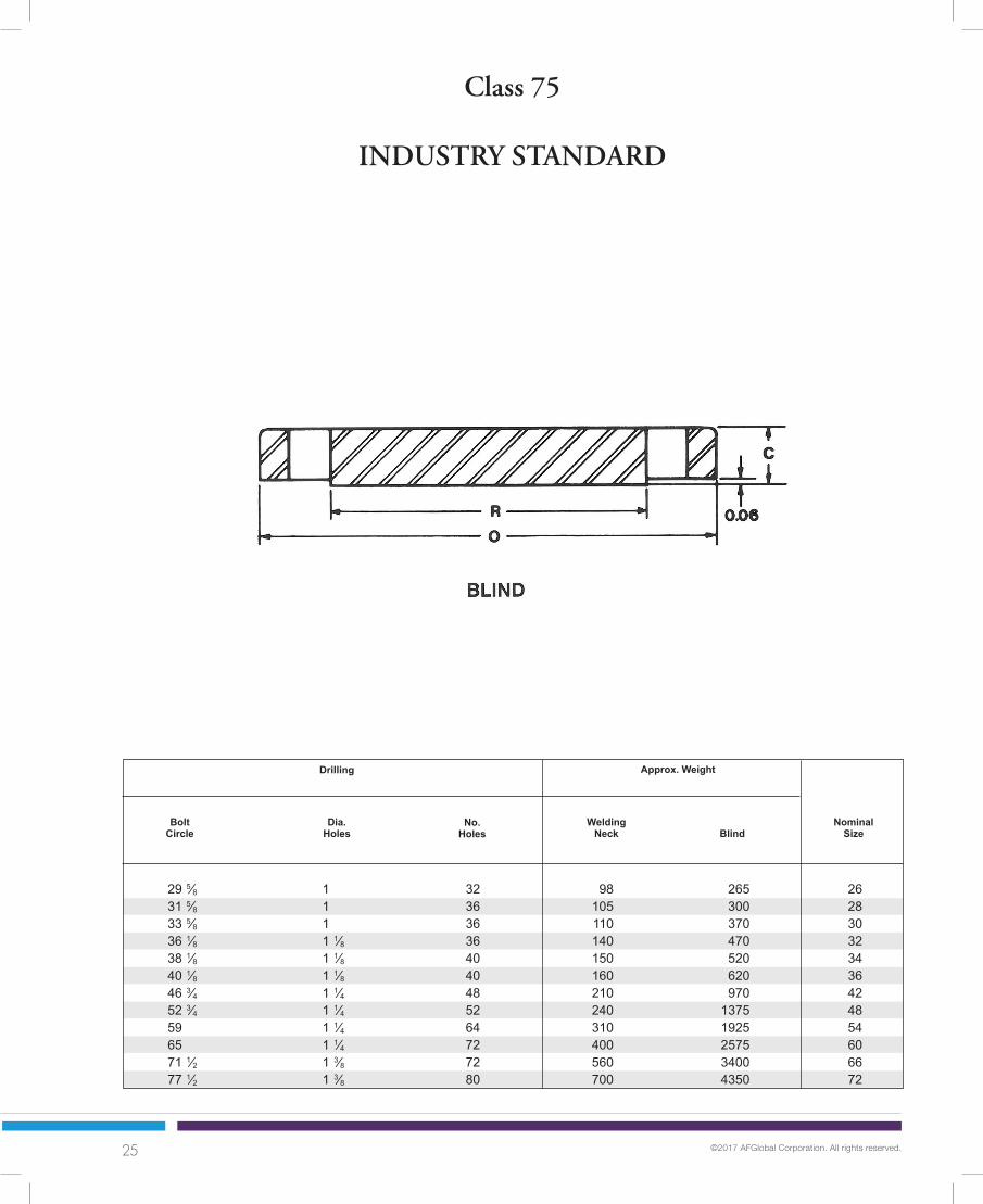
Class 75
API 605
WELDING NECK

21 ©2017 AFGlobal Corporation. All rights reserved.
BoltCircle
28 1⁄2 30 1⁄2 32 1⁄2 34 1⁄2 36 1⁄2 39 1⁄16
41 1⁄16
43 1⁄16
45 1⁄16
47 3⁄8 49 3⁄8 51 3⁄8 53 3⁄8 55 1⁄2 57 1⁄2 59 1⁄2 61 7⁄8 63 7⁄8
3⁄4 3⁄4 3⁄4 3⁄4 3⁄4 7⁄8 7⁄8 7⁄8 7⁄8 1 1 1 1 1 1 1 1⁄8 1 1⁄8 1 1⁄8
WeldingNeck Blind
Drilling
NominalSize
No.Holes
255290330390430518595760895
106511851315150516651840211023002500
262830323436384042444648505254565860
808590
105110145160170185230245270290310340400430475
Approx. Weight
Dia.Holes
Class 75
API 605
364044485240404448364044444848404444

22 ©2017 AFGlobal Corporation. All rights reserved.
NominalSize
33 35 37 39 1⁄2 41 1⁄2 43 1⁄2 50 56 62 1⁄2 68 1⁄2 75 1⁄2 81 1⁄2
OutsideDia.O
1 1⁄4 1 3⁄8 1 3⁄8 1 1⁄2 1 5⁄8 1 5⁄8 1 7⁄8 2 1⁄8 2 3⁄8 2 5⁄8 2 7⁄8 3 1⁄8
Slip-On Blind
ThicknessC
Dia.at Baseof Hub
X
1 1⁄4 1 1⁄4 1 1⁄4 1 1⁄4 1 1⁄4 1 1⁄4 1 1⁄4 1 1⁄4 1 3⁄8 1 5⁄8 1 3⁄4 2
BoreB
LengthThruHub
Y
30 32 34 36 1⁄4 38 1⁄4 40 1⁄4 46 1⁄2 52 1⁄2 59 65 71 5⁄8 77 5⁄8
O.D.RaisedFace
R
262830323436424854606672
2 1⁄4 2 1⁄4 2 1⁄4 2 1⁄2 2 1⁄2 2 1⁄2 2 3⁄4 2 7⁄8 3 1⁄8 3 5⁄8 4 4 1⁄2
Class 75
INDUSTRY STANDARD
26.2528.2530.2532.2534.2536.2542.2548.2554.2560.2566.2572.25
28 1⁄2 30 1⁄2 32 1⁄2 34 5⁄8 36 5⁄8 38 5⁄8 44 3⁄4 50 3⁄4 57 1⁄4 63 1⁄4 69 1⁄2 75 1⁄2
SLIP-ON

23 ©2017 AFGlobal Corporation. All rights reserved.
BoltCircle
31 33 35 37 3⁄8 39 3⁄8 41 3⁄8 47 3⁄4 53 3⁄4 60 1⁄4 66 1⁄4 73 79
1 1 1 1 1⁄8 1 1⁄8 1 1⁄8 1 1⁄4 1 1⁄4 1 1⁄4 1 1⁄4 1 3⁄8 1 3⁄8
Slip-On Blind
Drilling
NominalSize
No.Holes
290360405500600660
100014502000267535504500
262830323436424854606672
120140150170180190235270335450590730
Approx. Weight
Dia.Holes
Class 75
INDUSTRY STANDARD
323636404044485668727280

24 ©2017 AFGlobal Corporation. All rights reserved.
NominalSize
31 1⁄2 33 1⁄2 35 1⁄2 38 1⁄2 40 1⁄2 42 1⁄2 49 55 61 1⁄4 67 1⁄4 74 80
OutsideDia.O
1 1⁄4 1 1⁄4 1 3⁄8 1 1⁄2 1 1⁄2 1 5⁄8 1 7⁄8 2 1⁄8 2 3⁄8 2 5⁄8 2 7⁄8 3 1⁄8
WeldingNeck Blind
ThicknessC
Dia.at Baseof Hub
X
1 1⁄64
1 1⁄4 1 1⁄4 1 1⁄4 1 1⁄4 1 1⁄4 1 1⁄4 1 1⁄4 1 3⁄8 1 5⁄8 1 7⁄8 2 1⁄4
BoreB
LengthThruHub
Y
28 5⁄8 30 5⁄8 32 5⁄8 35 37 39 45 1⁄2 51 1⁄2 57 3⁄4 63 3⁄4 70 1⁄8 76 1⁄8
O.D.RaisedFace
R
262830323436424854606672
3 3 3 3 1⁄4 3 1⁄4 3 1⁄4 3 1⁄2 3 3⁄4 4 4 3⁄8 4 7⁄8 5 1⁄4
Class 75
INDUSTRY STANDARD
27 1⁄8 19 1⁄8 31 1⁄8 33 3⁄8 35 3⁄8 37 3⁄8 43 3⁄4 49 3⁄4 56 62 68 74
Dia.Hub atBevel
Y
To b
e sp
ecifi
ed b
y pu
rcha
ser.
To b
e sp
ecifi
ed b
y pu
rcha
ser.
WELDING NECK
25 ©2017 AFGlobal Corporation. All rights reserved.
BoltCircle
29 5⁄8 31 5⁄8 33 5⁄8 36 1⁄8 38 1⁄8 40 1⁄8 46 3⁄4 52 3⁄4 59 65 71 1⁄2 77 1⁄2
1 1 1 1 1⁄8 1 1⁄8 1 1⁄8 1 1⁄4 1 1⁄4 1 1⁄4 1 1⁄4 1 3⁄8 1 3⁄8
WeldingNeck Blind
Drilling
NominalSize
No.Holes
265300370470520620970
13751925257534004350
262830323436424854606672
98105110140150160210240310400560700
Approx. Weight
Dia.Holes
Class 75
INDUSTRY STANDARD
323636364040485264727280

26 ©2017 AFGlobal Corporation. All rights reserved.
NominalSize
11 13 1⁄2 16 19 21 23 1⁄2 25 27 1⁄2 29 1⁄2 32 34 1⁄4 36 1⁄2 38 3⁄4 41 3⁄4 43 3⁄4 46 48 3⁄4 50 3⁄4 53 55 1⁄4 57 1⁄4 59 1⁄2 61 3⁄4 64 66 1⁄4 73 80 86 1⁄2 99 3⁄4 113 1⁄4
OutsideDia.O
Slip-On125 LW,
B, D
Ring
ThicknessC
X
9⁄16
9⁄16
11⁄16
11⁄16
3⁄4 3⁄4 3⁄4 3⁄4 1 1 1 1 1 1 1⁄8 1 1⁄8 1 1⁄8 1 1⁄8 1 1⁄8 1 1⁄4 1 1⁄4 1 1⁄4 1 3⁄8 1 3⁄8 1 3⁄8 1 3⁄8 1 1⁄2 1 1⁄2 1 1⁄2 1 3⁄4 2
Bore Length Thru Hub
D
68
10121416182022242628303234363840424446485052546066728496
Class125 LW, AWWA C207 CLASSES B, D
6.728.72
10.8812.8814.1416.1618.1820.2022.2224.2526.2528.2530.2532.2534.2536.2538.2540.2542.2544.2546.2548.2550.2552.2554.2560.2566.2572.2584.2596.25
SLIP-ON
B
Hub Dia.X
11⁄16
11⁄16
11⁄16
11⁄16
11⁄16
11⁄16
11⁄16
11⁄16
3⁄4 3⁄4 13⁄16
7⁄8 7⁄8 15⁄16
15⁄16
1 1 1 1 1⁄8 1 1⁄8 1 1⁄8 1 1⁄4 1 1⁄4 1 1⁄4 1 11⁄32
1 1⁄2 1 5⁄8 1 3⁄4 2 2 1⁄4
11⁄16
11⁄16
11⁄16
13⁄16
15⁄16
1 1 1⁄16
1 1⁄8 1 3⁄16
1 1⁄4 1 5⁄16
1 5⁄16
1 3⁄8 1 1⁄2 1 1⁄2 1 5⁄8 1 5⁄8 1 5⁄8 1 3⁄4 1 3⁄4 1 3⁄4 1 3⁄4 2 2 2 1⁄8 2 1⁄4 2 1⁄2 2 5⁄8 2 3⁄4 3
7 9⁄16
9 11⁄16
12 14 3⁄8 15 3⁄4 18 19 7⁄8 22 24 1⁄4 26 1⁄8 28 1⁄2 30 1⁄2 32 1⁄2 34 3⁄4 36 3⁄4 38 3⁄4 40 3⁄4 43 45 47 49 51 53 55 57 63 69 75 87 1⁄2 100
1 1⁄4 1 1⁄4 1 1⁄4 1 1⁄4 1 1⁄4 1 1⁄4 1 1⁄4 1 1⁄4 1 3⁄4 1 3⁄4 1 3⁄4 1 3⁄4 1 3⁄4 1 3⁄4 1 3⁄4 1 3⁄4 1 3⁄4 1 3⁄4 1 3⁄4 2 1⁄4 2 1⁄4 2 1⁄2 2 1⁄2 2 1⁄2 2 1⁄2 2 3⁄4 2 3⁄4 2 3⁄4 3 3 1⁄4
Note: Blind Flanges will be furnished to thicknesses listed above, unless otherwise specified.

27 ©2017 AFGlobal Corporation. All rights reserved.
BoltCircle
3⁄4 3⁄4 3⁄4 3⁄4 7⁄8 7⁄8 7⁄8 7⁄8 7⁄8 7⁄8 7⁄8 7⁄8 1 1 1 1 1 1 1 1⁄8 1 1⁄8 1 1⁄8 1 1⁄8 1 1⁄4 1 1⁄4 1 3⁄8 1 3⁄8 1 3⁄8 1 3⁄8 1 5⁄8 1 7⁄8
Slip-On
125 LW, B & D D
Drilling
NominalSize
No.Holes
121520335060658090
110130145165210220265300315365385400430500540615760
1025120015752125
131826424458596976
115125140150205215235265280330350365425450475500640750850
12251725
Approx. Weight
Dia.Holes
B
88
12121216162020202428282832323236364040444444445252606468
Class125 LW, AWWA C207 CLASSES B, D
125 LWD
Size B
1114203036434550607085
100110145150175200205250265275325340360420535799840
12001665
7⁄8 7⁄8 1 1 1 1⁄8 1 1⁄8 1 1⁄4 1 1⁄4 1 3⁄8 1 3⁄8 1 3⁄8 1 3⁄8 1 3⁄8 1 5⁄8 1 5⁄8 1 5⁄8 1 5⁄8 1 5⁄8 1 5⁄8 1 5⁄8 1 5⁄8 1 5⁄8 1 7⁄8 1 7⁄8 1 7⁄8 1 7⁄8 1 7⁄8 1 7⁄8 2 1⁄8 2 3⁄8
9 1⁄2 11 3⁄4 14 1⁄4 17 18 3⁄4 21 1⁄4 22 3⁄4 25 27 1⁄4 29 1⁄2 31 3⁄4 34 36 38 1⁄2 40 1⁄2 42 3⁄4 45 1⁄4 47 1⁄4 49 1⁄2 51 3⁄4 53 3⁄4 56 58 1⁄4 60 1⁄2 62 3⁄4 69 1⁄4 76 82 1⁄2 95 1⁄2 108 1⁄2
Bolt Hole Dia. Ring
68
10121416182022242628303234363840424446485052546066728496

28 ©2017 AFGlobal Corporation. All rights reserved.
NominalSize
11 13 1⁄2 16 19 21 23 1⁄2 25 27 1⁄2 29 1⁄2 32 34 1⁄4 36 1⁄2 38 3⁄4 41 3⁄4 43 3⁄4 46 48 3⁄4 50 3⁄4 53 55 1⁄4 57 1⁄4 59 1⁄2 61 3⁄4 64 66 1⁄4 73 80 86 1⁄2 99 3⁄4 113 1⁄4
OutsideDia.O
ThicknessC
1 1 1⁄8 1 3⁄16
1 1⁄4 1 3⁄8 1 7⁄16
1 9⁄16
1 11⁄16
1 13⁄16
1 7⁄8 2 2 1⁄16
2 1⁄8 2 1⁄4 2 5⁄16
2 3⁄8 2 3⁄8 2 1⁄2 2 5⁄8 2 5⁄8 2 11⁄16
2 3⁄4 2 3⁄4 2 7⁄8 3 3 1⁄8 3 3⁄8 3 1⁄2 3 7⁄8 4 1⁄4
Bore Length Thru Hub
68
10121416182022242628303234363840424446485052546066728496
Class125 & AWWA C207 CLASS E
6.728.72
10.8812.8814.1416.1618.1820.2022.2224.2526.2528.2530.2532.2534.2536.2538.2540.2542.2544.2546.2548.2550.2552.2554.2560.2566.2572.2584.2596.25
WELDING NECK
X
Hub Dia.X
7 9⁄16
9 11⁄16
12 14 3⁄8 15 3⁄4 18 19 7⁄8 22 24 1⁄4 26 1⁄8 28 1⁄2 30 3⁄4 32 3⁄4 35 37 39 1⁄4 41 3⁄4 43 3⁄4 46 48 50 52 1⁄4 54 1⁄4 56 1⁄2 58 3⁄4 65 1⁄4 71 1⁄2 78 1⁄2 90 1⁄2 102 3⁄4
3 1⁄2 4 4 4 1⁄2 5 5 5 1⁄2 5 11⁄16
5 7⁄8 6 5 5 1⁄16
5 1⁄8 5 1⁄4 5 5⁄16
5 3⁄8 5 3⁄8 5 1⁄2 5 5⁄8 5 5⁄8 5 11⁄16
5 3⁄4 5 3⁄4 5 7⁄8 6 6 1⁄8 6 3⁄8 6 1⁄2 6 7⁄8 7 1⁄4
Note: Blind Flanges will be furnished to thicknesses listed above, unless otherwise specified.
C
WeldingNeck
B1
Slip-OnB2
Slip-OnY2
WeldingNeck
Y1To
be
spec
ified
by
purc
hase
r.
1 9⁄16
1 3⁄4 1 15⁄16
2 3⁄16
2 1⁄4 2 1⁄2 2 11⁄16
2 7⁄8 3 1⁄8 3 1⁄4 3 3⁄8 3 7⁄16
3 1⁄2 3 5⁄8 3 11⁄16
3 3⁄4 3 3⁄4 3 7⁄8 4 4 4 1⁄16
4 1⁄8 4 1⁄8 4 1⁄4 4 3⁄8 4 1⁄2 4 7⁄8 5 5 3⁄8 5 3⁄4

29 ©2017 AFGlobal Corporation. All rights reserved.
BoltCircle
Slip-On
Drilling
NominalSize
No.Holes
193043648593
120155175210235270305375400450530570650690730800830920
102512501625192526003275
Approx. Weight
Dia.Holes
88
12121216162020202428282832323236364040444444445252606468
Class 125 & AWWA C207 CLASS E
WeldingNeck
24395280
110140150180225255265295340410440495570620710750800870900
1000110013501775210028253800
7⁄8 7⁄8 1 1 1 1⁄8 1 1⁄8 1 1⁄4 1 1⁄4 1 3⁄8 1 3⁄8 1 3⁄8 1 3⁄8 1 3⁄8 1 5⁄8 1 5⁄8 1 5⁄8 1 5⁄8 1 5⁄8 1 5⁄8 1 5⁄8 1 5⁄8 1 5⁄8 1 7⁄8 1 7⁄8 1 7⁄8 1 7⁄8 1 7⁄8 1 7⁄8 2 1⁄8 2 3⁄8
68
10121416182022242628303234363840424446485052546066728496
6.638.63
10.7512.7514.0016.0018.0020.0022.0024.0026.0028.0030.0032.0034.0036.0038.0040.0042.0044.0046.0048.0050.0052.0054.0060.0066.0072.0084.0096.00
Dia.Hub atBevel
A
9 1⁄2 11 3⁄4 14 1⁄4 17 18 3⁄4 21 1⁄4 22 3⁄4 25 27 1⁄4 29 1⁄2 31 3⁄4 34 36 38 1⁄2 40 1⁄2 42 3⁄4 45 1⁄4 47 1⁄4 49 1⁄2 51 3⁄4 53 3⁄4 56 58 1⁄4 60 1⁄2 62 3⁄4 69 1⁄4 76 82 1⁄2 95 1⁄2 108 1⁄2

30 ©2017 AFGlobal Corporation. All rights reserved.
NominalSize
34 1⁄4 36 1⁄2 38 3⁄4 41 3⁄4 43 3⁄4 46 48 3⁄4 50 3⁄4 53 55 1⁄4 57 1⁄4 59 1⁄2 61 3⁄4 64 66 1⁄4 68 3⁄4 71 73
OutsideDia.O
3⁄8 7⁄16
7⁄16
7⁄16
1⁄2 1⁄2 1⁄2 1⁄2 1⁄2 1⁄2 1⁄2 1⁄2 1⁄2 1⁄2 1⁄2 1⁄2 1⁄2 1⁄2
Drilling
FilletRadius
r
2 11⁄16
2 13⁄16
2 15⁄16
3 3⁄16
3 1⁄4 3 9⁄16
3 7⁄16
3 9⁄16
3 13⁄16
4 4 1⁄16
4 1⁄4 4 3⁄8 4 9⁄16
4 3⁄4 4 7⁄8 5 1⁄16
5 3⁄16
To b
e sp
ecifi
ed b
y pu
rcha
ser.
BoreB
Dia.Holes
No.Holes
Approx.Wt.
WNF
26 5⁄8 28 5⁄8 30 5⁄8 32 5⁄8 34 5⁄8 36 13⁄16
38 13⁄16
40 13⁄16
42 13⁄16
44 7⁄8 46 7⁄8 48 7⁄8 50 15⁄16
52 15⁄16
55 57 1⁄8 59 1⁄8 61 1⁄8
4 3⁄4 4 15⁄16
5 3⁄8 5 11⁄16
5 7⁄8 6 3⁄16
6 3⁄16
6 7⁄16
6 3⁄4 7 7 15⁄16
7 9⁄16
8 8 1⁄4 8 1⁄2 9 9 1⁄4 9 7⁄16
Dia.Hub atBevel
A
262830323436384042444648505254565860
31 3⁄4 34 36 38 1⁄2 40 1⁄2 42 3⁄4 45 1⁄4 47 1⁄4 49 1⁄2 51 3⁄4 53 3⁄4 56 58 1⁄4 60 1⁄2 62 3⁄4 65 67 1⁄4 69 1⁄4
242828283232323636404044444444484852
Class 150
MSS-SP-44
WELDING NECK
LengthThruHub
Y
BoltCircle
HubDia.
X
Thickness(Min.)
C
RaisedFaceDia.R
To b
e sp
ecifi
ed b
y pu
rcha
ser.
29 1⁄2 31 1⁄2 33 3⁄4 36 38 40 1⁄4 42 1⁄4 44 1⁄4 47 49 51 53 1⁄2 55 1⁄2 57 1⁄2 59 1⁄2 62 64 66
1 3⁄8 1 3⁄8 1 3⁄8 1 5⁄8 1 5⁄8 1 5⁄8 1 5⁄8 1 5⁄8 1 5⁄8 1 5⁄8 1 5⁄8 1 5⁄8 1 7⁄8 1 7⁄8 1 7⁄8 1 7⁄8 1 7⁄8 1 7⁄8
300345400505540640720775890990
10601185127014101585176019152045

31 ©2017 AFGlobal Corporation. All rights reserved.
Class 150
API 605
NominalSize
30 15⁄16
32 15⁄16
34 15⁄16
37 1⁄16
39 9⁄16
41 5⁄8 44 1⁄4 46 1⁄4 48 1⁄4 50 1⁄4 52 13⁄16
54 13⁄16
56 13⁄16
58 13⁄16
61 63 65 15⁄16
67 15⁄16
OutsideDia.O
Drilling
FilletRadius
r
To b
e sp
ecifi
ed b
y pu
rcha
ser.
BoreB
Dia.Holes
No.Holes
Approx.Wt.
WNF
26 15⁄8 28 15⁄16
31 33 1⁄16
35 1⁄8 37 3⁄16
39 1⁄4 41 5⁄16
43 3⁄8 45 3⁄8 47 1⁄16
49 1⁄2 51 1⁄2 53 9⁄16
55 5⁄8 57 11⁄16
59 11⁄16
61 13⁄16
3 1⁄2 3 3⁄4 3 15⁄16
4 1⁄4 4 11⁄32
4 5⁄8 4 7⁄8 5 1⁄16
5 1⁄4 5 3⁄8 5 11⁄16
5 7⁄8 6 1⁄16
6 3⁄16
6 3⁄8 6 9⁄16
6 7⁄8 7 1⁄16
Dia.Hub atBevel
A
262830323436384042444648505254565860
LengthThruHub
Y
BoltCircle
HubDia.
X
Thickness(Min.)
C
RaisedFaceDia.R
To b
e sp
ecifi
ed b
y pu
rcha
ser.
28 30 32 34 36 1⁄4 38 1⁄4 40 1⁄4 42 1⁄2 44 1⁄2 46 1⁄2 48 5⁄8 50 3⁄4 52 3⁄4 54 3⁄4 56 3⁄4 58 3⁄8 60 3⁄4 63
120140150170210240290310345370435480520550620650780850
1 5⁄8 1 3⁄4 1 3⁄4 1 13⁄16
1 15⁄16
1 13⁄16
2 1⁄16
2 1⁄8 2 3⁄16
2 5⁄16
2 7⁄16
2 9⁄16
2 11⁄16
2 3⁄4 2 13⁄16
2 7⁄8 2 15⁄16
3
3⁄8 3⁄8 3⁄8 3⁄8 3⁄8 3⁄8 3⁄8 3⁄8 7⁄16
7⁄16
7⁄16
7⁄16
7⁄16
7⁄16
7⁄16
9⁄16
9⁄16
9⁄16
29 3⁄8 31 5⁄16
33 5⁄16
35 7⁄16
37 11⁄16
39 3⁄4 42 1⁄8 44 1⁄8 46 1⁄8 48 1⁄8 50 9⁄16
52 9⁄16
54 9⁄16
56 9⁄16
58 3⁄4 60 3⁄4 63 7⁄16
65 7⁄16
364044484044404448524044485256604852
7⁄8 7⁄8 7⁄8 7⁄8 1 1 1 1⁄8 1 1⁄8 1 1⁄8 1 1⁄8 1 1⁄4 1 1⁄4 1 1⁄4 1 1⁄4 1 1⁄4 1 1⁄4 1 3⁄8 1 3⁄8

32 ©2017 AFGlobal Corporation. All rights reserved.
Nominal
Size
34 1⁄4 36 1⁄2 38 3⁄4 41 3⁄4 43 3⁄4 46 48 3⁄4 50 3⁄4 53 55 57 1⁄4 59 1⁄2
FlangeO.D.
O
3⁄8 7⁄16
7⁄16
7⁄16
1⁄2 1⁄2 1⁄2 1⁄2 1⁄2 1⁄2 1⁄2 1⁄2
FilletRadius
r
2 11⁄16
3 1⁄16
3 5⁄16
3 27⁄64
3 11⁄16
3 31⁄32
4 1⁄16
4 3⁄16
4 7⁄16
4 11⁄16
4 55⁄64
5 1⁄16
Flange Bore
B2
Dia.Holes
No.Holes
28 1⁄4 30 1⁄2 32 1⁄2 34 1⁄2 36 1⁄2 38 3⁄4 41 1⁄4 43 1⁄4 45 1⁄2 47 3⁄4 49 3⁄4 52
3 11⁄16
3 13⁄16
3 15⁄16
4 3⁄16
4 1⁄4 4 9⁄16
4 9⁄16
4 13⁄16
5 1⁄16
5 3⁄16
5 5⁄16
5 9⁄16
262830323436384042444648
31 3⁄4 34 36 38 1⁄2 40 1⁄2 42 3⁄4 45 1⁄4 47 1⁄4 49 1⁄2 51 3⁄4 53 3⁄4 56
242828283232323636404044
Class 150
MSS-SP-44
LengthThruHubY2
BoltCircle
HubDia.
X
FlangeThickness
C
RaisedFaceDia.R
29 1⁄2 31 1⁄2 33 3⁄4 36 38 40 1⁄4 42 1⁄4 44 1⁄4 47 49 51 53 1⁄2
1 3⁄8 1 3⁄8 1 3⁄8 1 5⁄8 1 5⁄8 1 5⁄8 1 5⁄8 1 5⁄8 1 5⁄8 1 5⁄8 1 5⁄8 1 5⁄8
26.2528.2530.2532.2534.2536.2538.2540.2542.2544.2546.2548.25
FACING AND DRILLING MATCHES MSS-SP-44 CLASS 150 FLANGES

33 ©2017 AFGlobal Corporation. All rights reserved.
Class 175
INDUSTRY STANDARD
NominalSize
31 1⁄2 33 1⁄2 35 3⁄4 37 3⁄4 40 1⁄4 42 1⁄4 44 1⁄4 46 1⁄4 49 51 53 55 57 59 1⁄2 61 1⁄2 67 1⁄2 73 1⁄2 80
OutsideDia.O
Length Thru HubY
B2
RaisedFaceDia.R
Slip-On
Dia.Hub at Bevel
A
29 31 33 1⁄4 35 1⁄4 37 3⁄8 39 3⁄8 41 3⁄8 43 3⁄8 45 3⁄4 47 3⁄4 49 3⁄4 51 3⁄4 53 3⁄4 56 58 64 70 76 1⁄2
B1
262830323436384042444648505254606672
HubDia.
X
WeldingNeckBlind
WeldingNeck
Slip-On
To b
e sp
ecifi
ed b
y pu
rcha
ser.
1 3⁄8 1 3⁄8 1 3⁄8 1 3⁄8 1 1⁄2 1 1⁄2 1 3⁄4 1 3⁄4 2 2 2 2 1⁄4 2 1⁄4 2 5⁄8 2 5⁄8 2 3⁄4 3 1⁄8 3 5⁄8
WELDING NECK
ThicknessC
Bore
2 3⁄4 2 3⁄4 2 3⁄4 2 3⁄4 3 3⁄8 3 3⁄8 3 3⁄4 4 4 3⁄8 4 3⁄8 4 5⁄8 4 7⁄8 4 7⁄8 5 3⁄8 5 3⁄8 5 7⁄8 6 7⁄8 8
27 5⁄8 29 5⁄8 31 7⁄8 33 7⁄8 35 7⁄8 37 7⁄8 39 7⁄8 41 7⁄8 44 1⁄8 46 1⁄8 48 1⁄8 50 1⁄8 52 1⁄8 54 1⁄4 56 1⁄4 62 1⁄4 68 1⁄2 74 1⁄2
1 3⁄8 1 3⁄8 1 3⁄8 1 3⁄8 1 3⁄4 1 3⁄4 2 2 2 3⁄8 2 3⁄8 2 3⁄8 2 5⁄8 2 5⁄8 3 3 3 1⁄8 4 5
1 7⁄8 2 2 1⁄8 2 1⁄4 2 3⁄8 2 1⁄2 2 5⁄8 2 3⁄4 2 7⁄8 3 3 1⁄8 3 3⁄8 3 3⁄8 3 5⁄8 3 5⁄8 4 4 3⁄8 4 3⁄4
26.2528.2530.2532.2534.2536.2538.2540.2542.2544.2546.2548.2550.2552.2554.2560.2566.2572.25
3 3⁄8 3 3⁄8 3 5⁄8 3 5⁄8 3 3⁄4 3 3⁄4 4 1⁄8 4 1⁄8 4 1⁄2 4 1⁄2 4 1⁄2 4 7⁄8 4 7⁄8 5 3⁄8 5 3⁄8 5 3⁄4 6 1⁄8 6 5⁄8
To b
e sp
ecifi
ed b
y pu
rcha
ser.

34 ©2017 AFGlobal Corporation. All rights reserved.
BoltCircleDia.
29 7⁄8 31 7⁄8 34 1⁄8 36 1⁄8 38 3⁄8 40 3⁄8 42 3⁄8 44 3⁄8 46 7⁄8 48 7⁄8 50 7⁄8 52 7⁄8 54 7⁄8 57 1⁄4 59 1⁄4 65 1⁄4 71 1⁄4 77 3⁄4
7⁄8 7⁄8 7⁄8 7⁄8 1 1 1 1 1 1⁄8 1 1⁄8 1 1⁄8 1 1⁄8 1 1⁄8 1 1⁄4 1 1⁄4 1 1⁄4 1 1⁄4 1 1⁄4
WeldingNeck
Slip-On
Drilling
NominalSize
No.Holes
105115130140200210250270365380410460480600620730
10001400
262830323436384042444648505254606672
120130150160195205245255340360375430450560580680830
1075
Approx. Weight
Dia.Holes
Class 175
INDUSTRY STANDARD
282836363636364040404044444444485664
Blind
405490590700840970
112513001500170019252225240028003000400051756650

35 ©2017 AFGlobal Corporation. All rights reserved.
Nominal
Size
38 1⁄4 40 3⁄4 43 45 1⁄4 47 2⁄3 50 53 2⁄4 54 1⁄2 57 59 1⁄4 61 1⁄4 65
Dia.of
FlangeO
Dia. of Std. Raised
Face PerANSI B16.1
2 13⁄16
2 15⁄16
3 3 1⁄8 3 1⁄4 3 3⁄8 3 7⁄16
3 9⁄16
3 11⁄16
3 3⁄4 3 7⁄8 4
Approx.Weight
PerFlange
No.Bolt
Holes
LengthThruHub
Y
30 1⁄2 33 35 1⁄4 37 1⁄2 39 1⁄2 41 1⁄2 43 1⁄2 45 3⁄4 47 3⁄4 49 3⁄4 51 3⁄4 55
262830323436384042444648
32 7⁄16
34 15⁄16
37 3⁄16
39 7⁄16
41 7⁄16
43 11⁄16
45 11⁄16
47 15⁄16
50 7⁄16
52 11⁄16
54 1⁄4 58 7⁄16
Class 250 Welding Neck
B 16.1
Dia.of
BoreB
Dia.Bolt
Holes
Thick.of
FlangeC
LargeDia. ofHub
X
BoltCircleDia.
34 1⁄2 37 39 1⁄4 41 1⁄2 43 1⁄2 46 48 50 1⁄4 52 3⁄4 55 57 1⁄4 60 3⁄4
1 7⁄8 1 7⁄8 1 7⁄8 1 7⁄8 1 7⁄8 2 1⁄8 2 1⁄8 2 1⁄8 2 1⁄8 2 1⁄8 2 1⁄8 2 1⁄8
534629702793882969
105711581318142315361824To
be
spec
ified
by
purc
hase
r. 5 13⁄16
5 15⁄16
6 6 1⁄8 6 1⁄4 6 3⁄8 6 7⁄16
6 9⁄16
6 15⁄16
7 7 1⁄8 7 1⁄4
282828282832323636364040
Dia. of Std. Raised
Face PerANSI B16.1
29 1⁄2 31 1⁄2 33 3⁄4 36 38 40 1⁄4 42 1⁄4 44 1⁄4 47 49 51 53 1⁄2

36 ©2017 AFGlobal Corporation. All rights reserved.
Nominal
Size
38 1⁄4 40 3⁄4 43 45 2⁄4 47 2⁄3 50 53 2⁄4 54 1⁄2 57 59 1⁄4 61 1⁄4 65
Dia.of
FlangeO
Dia. of Std. Raised
Face PerANSI B16.1
2 13⁄16
2 15⁄16
3 3 1⁄8 3 1⁄4 3 3⁄8 3 7⁄16
3 9⁄16
3 11⁄16
3 3⁄4 3 7⁄8 4
Approx.Weight
PerFlange
No.Bolt
Holes
LengthThruHub
Y
30 1⁄2 33 35 1⁄4 37 1⁄2 39 1⁄2 41 1⁄2 43 1⁄2 45 3⁄4 47 3⁄4 49 3⁄4 51 3⁄4 55
262830323436384042444648
32 7⁄16
34 15⁄16
37 3⁄16
39 7⁄16
41 7⁄16
43 11⁄16
45 11⁄16
47 15⁄16
50 7⁄16
52 11⁄16
54 1⁄4 58 7⁄16
Class 250 Slip-On
B 16.1
Dia.of
BoreB
Dia.Bolt
Holes
Thick.of
FlanceC
LargeDia. ofHub
X
BoltCircleDia.
34 1⁄2 37 39 1⁄4 41 1⁄2 43 1⁄2 46 48 50 1⁄4 52 3⁄4 55 57 1⁄4 60 3⁄4
1 7⁄8 1 7⁄8 1 7⁄8 1 7⁄8 1 7⁄8 2 1⁄8 2 1⁄8 2 1⁄8 2 1⁄8 2 1⁄8 2 1⁄8 2 1⁄8
531637707810889970
106211721288139715101797
4 3⁄4 5 5 5 1⁄8 5 1⁄4 5 3⁄8 5 1⁄2 5 1⁄2 5 5⁄8 5 3⁄4 5 7⁄8 6
282828282832323636364040
Dia. of Std. Raised
Face PerANSI B16.1
29 1⁄2 31 1⁄2 33 3⁄4 36 38 40 1⁄4 42 1⁄4 44 1⁄4 47 49 51 53 1⁄2
26 1⁄4 28 1⁄4 30 1⁄4 32 1⁄4 34 1⁄4 36 1⁄4 38 1⁄4 40 1⁄4 42 1⁄4 44 1⁄4 46 1⁄4 48 1⁄4
Blinds available upon request.
37 ©2017 AFGlobal Corporation. All rights reserved.
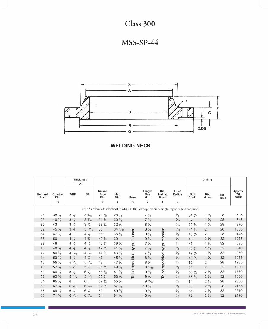
Class 300
MSS-SP-44
NominalSize
38 1⁄4 40 3⁄4 43 45 1⁄4 47 1⁄2 50 46 48 3⁄4 50 3⁄4 53 1⁄4 55 1⁄4 57 3⁄4 60 1⁄4 62 1⁄4 65 1⁄4 67 1⁄4 69 1⁄4 71 1⁄4
OutsideDia.O
FilletRadius
r
RaisedFaceDia.R
Dia. Holes
Approx.Wt.
WNF
29 1⁄2 31 1⁄4 33 3⁄4 36 38 40 1⁄8 40 1⁄2 42 3⁄4 44 3⁄4 47 49 51 1⁄4 53 1⁄2 55 1⁄2 57 3⁄4 59 3⁄4 62 64
BoreB
262830323436384042444648505254565860
HubDia.
X
BoltCircle
WNF BF
To b
e sp
ecifi
ed b
y pu
rcha
ser.
3 1⁄8 3 3⁄8 3 5⁄8 3 7⁄8 4 4 1⁄8 4 1⁄4 4 1⁄2 4 11⁄16
4 7⁄8 5 1⁄16
5 1⁄4 5 1⁄2 5 11⁄16
6 6 1⁄16
6 1⁄4 6 7⁄16
WELDING NECK
ThicknessC
28 3⁄8 30 1⁄2 32 9⁄16
34 11⁄16
36 7⁄8 39 39 1⁄8 41 1⁄4 43 1⁄4 45 1⁄4 47 3⁄8 49 3⁄8 51 3⁄8 53 3⁄8 55 1⁄2 57 5⁄8 59 5⁄8 61 5⁄8
1 3⁄4 1 3⁄4 1 7⁄8 2 2 2 1⁄8 1 5⁄8 1 3⁄4 1 3⁄4 1 7⁄8 2 2 2 1⁄8 2 1⁄8 2 3⁄8 2 3⁄8 2 3⁄8 2 3⁄8
LengthThruHub
Y
Dia.Hub atBevel
A
No.Holes
To b
e sp
ecifi
ed b
y pu
rcha
ser.
7 1⁄4 7 3⁄4 8 1⁄4 8 3⁄4 9 1⁄8 9 1⁄2 7 1⁄8 7 5⁄8 7 7⁄8 8 1⁄8 8 1⁄2 8 13⁄16
9 1⁄8 9 3⁄8 9 15⁄16
10 1⁄4 10 1⁄2 10 3⁄4
3⁄8 7⁄16
7⁄16
7⁄16
1⁄2 1⁄2 1⁄2 1⁄2 1⁄2 1⁄2 1⁄2 1⁄2 1⁄2 1⁄2 1⁄2 1⁄2 1⁄2 1⁄2
605745870
100511451275
695840950
105512351380153016602050215522702470
282828282832323232322832323228283232
34 1⁄2 37 39 1⁄4 41 1⁄2 43 1⁄2 46 43 45 1⁄2 47 1⁄2 49 3⁄4 52 54 56 1⁄4 58 1⁄4 61 63 65 67
Drilling
3 5⁄16
3 9⁄16
3 3⁄4 3 15⁄16
4 1⁄8 4 3⁄8 4 1⁄4 4 1⁄2 4 11⁄16
4 7⁄8 5 1⁄16
5 1⁄4 5 1⁄2 5 11⁄16
6 6 1⁄16
6 1⁄4 6 7⁄16
Sizes 12” thru 24” identical to ANSI B16.5 except when a single taper hub is required.

38 ©2017 AFGlobal Corporation. All rights reserved.
NominalSize
34 1⁄8 36 1⁄4 39 41 1⁄2 43 5⁄8 46 1⁄8 48 1⁄8 50 1⁄8 52 1⁄2 54 1⁄2 57 1⁄2 59 1⁄2 61 1⁄2 63 1⁄2 65 7⁄8 69 1⁄2 71 15⁄16
73 15⁄16
OutsideDia.O
9⁄16
9⁄16
9⁄16
5⁄8 5⁄8 5⁄8 5⁄8 5⁄8 5⁄8 5⁄8 5⁄8 5⁄8 5⁄8 5⁄8 5⁄8 11⁄16
11⁄16
11⁄16
Drilling
FilletRadius
r
3 1⁄2 3 1⁄2 3 11⁄16
4 1⁄16
4 1⁄16
4 1⁄16
4 3⁄8 4 9⁄16
4 11⁄16
5 5 1⁄16
5 1⁄16
5 7⁄16
5 5⁄8 5 3⁄8 6 1⁄16
6 1⁄16
5 15⁄16
To b
e sp
ecifi
ed b
y pu
rcha
ser.
BoreB
Dia.Holes
No.Holes
Approx.Wt.
WNF
27 5⁄8 29 3⁄4 32 34 36 1⁄8 38 40 42 44 46 3⁄16
48 3⁄8 50 5⁄16
52 3⁄8 54 7⁄16
56 1⁄2 58 1⁄2 60 15⁄16
62 15⁄16
5 11⁄16
5 7⁄8 6 15⁄64
6 5⁄8 6 13⁄16
7 1⁄8 7 9⁄16
7 13⁄16
8 1⁄16
8 7⁄16
8 3⁄4 8 13⁄16
9 1⁄4 9 9⁄16
9 7⁄16
10 9⁄16
10 13⁄16
10 11⁄16
Dia.Hub atBevel
A
262830323436384042444648505254565860
31 5⁄8 33 3⁄4 36 1⁄4 38 1⁄2 40 5⁄8 42 7⁄8 44 7⁄8 46 7⁄8 49 51 53 3⁄4 55 3⁄4 57 3⁄4 59 3⁄4 62 1⁄8 65 67 7⁄16
69 7⁄16
323636323632364036403640444848364040
Class 300
API 605
LengthThruHub
Y
BoltCircle
HubDia.
X
Thickness(Min.)
C
RaisedFaceDia.R
To b
e sp
ecifi
ed b
y pu
rcha
ser.
29 31 33 1⁄4 35 1⁄2 37 1⁄2 39 3⁄4 41 3⁄4 43 7⁄8 46 48 50 52 1⁄4 54 1⁄4 56 1⁄4 58 1⁄4 60 1⁄2 62 3⁄4 65
1 3⁄8 1 3⁄8 1 1⁄2 1 5⁄8 1 5⁄8 1 3⁄4 1 3⁄4 1 3⁄4 1 7⁄8 1 7⁄8 2 2 2 2 2 2 3⁄8 2 3⁄8 2 3⁄8
400450550685750840915990
1135123514701575171018401980259527702870

39 ©2017 AFGlobal Corporation. All rights reserved.
PipeSize
38 1⁄4 40 3⁄4 43 45 1⁄4 47 1⁄2 50 46 48 3⁄4 50 3⁄4 53 1⁄4 55 3⁄4 57 3⁄4
FlangeO.D.
O
3 1⁄8 3 3⁄8 3 5⁄8 3 7⁄8 4 4 1⁄8 5 5⁄16
5 9⁄16
5 13⁄16
6 1⁄16
6 5⁄16
6 9⁄16
FlangeBore
B2
No.Bolt
Holes
FlangeLength
Y2
30 1⁄4 32 3⁄4 34 3⁄4 36 3⁄4 38 3⁄4 41 39 41 1⁄4 43 1⁄4 45 1⁄4 47 1⁄4 49 1⁄4
262830323436384042444648
Class 300
MSS-SP-44
Dia.Bolt
Holes
FlangeThickness
C
HubDia.
X
Dia.Bolt
Circle
34 1⁄2 37 39 1⁄4 41 1⁄2 43 1⁄2 46 43 45 1⁄2 47 1⁄2 49 3⁄4 52 54
1 3⁄4 1 3⁄4 1 7⁄8 2 2 2 1⁄8 1 5⁄8 1 3⁄4 1 3⁄4 1 7⁄8 2 2
26.2528.2530.2532.2534.2536.2538.2540.2542.2544.2546.2548.25
5 3⁄8 5 11⁄16
6 1⁄8 6 9⁄16
6 13⁄16
7 1⁄16
6 1⁄16
6 9⁄16
6 13⁄16
6 7⁄8 7 1⁄16
7 3⁄16
282828282832323232322832
29 1⁄2 31 1⁄2 33 3⁄4 36 38 40 1⁄4 42 1⁄4 44 1⁄4 47 49 51 53 1⁄2
Dia.Face
R
3⁄8 7⁄16
7⁄16
7⁄16
1⁄2 1⁄2 1⁄2 1⁄2 1⁄2 1⁄2 1⁄2 1⁄2
FilletRad. Min.
40 ©2017 AFGlobal Corporation. All rights reserved.
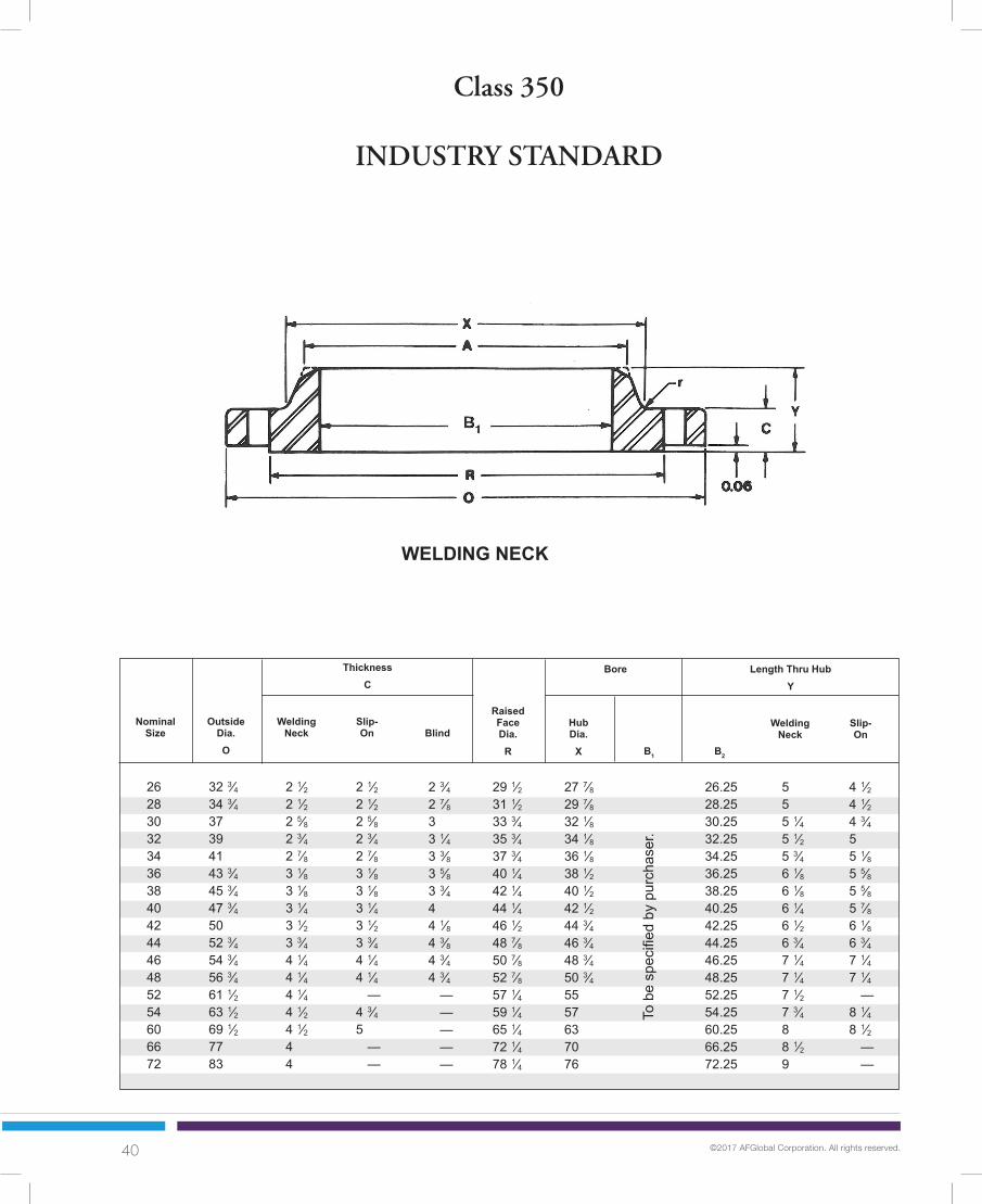
Class 350
INDUSTRY STANDARD
NominalSize
32 3⁄4 34 3⁄4 37 39 41 43 3⁄4 45 3⁄4 47 3⁄4 50 52 3⁄4 54 3⁄4 56 3⁄4 61 1⁄2 63 1⁄2 69 1⁄2 77 83
OutsideDia.O
Length Thru HubY
B2
RaisedFaceDia.R
Slip-On
29 1⁄2 31 1⁄2 33 3⁄4 35 3⁄4 37 3⁄4 40 1⁄4 42 1⁄4 44 1⁄4 46 1⁄2 48 7⁄8 50 7⁄8 52 7⁄8 57 1⁄4 59 1⁄4 65 1⁄4 72 1⁄4 78 1⁄4
B1
2628303234363840424446485254606672
HubDia.
X
WeldingNeckBlind
WeldingNeck
Slip-On
To b
e sp
ecifi
ed b
y pu
rcha
ser.
2 1⁄2 2 1⁄2 2 5⁄8 2 3⁄4 2 7⁄8 3 1⁄8 3 1⁄8 3 1⁄4 3 1⁄2 3 3⁄4 4 1⁄4 4 1⁄4 4 1⁄4 4 1⁄2 4 1⁄2 4 4
WELDING NECK
ThicknessC
Bore
4 1⁄2 4 1⁄2 4 3⁄4 5 5 1⁄8 5 5⁄8 5 5⁄8 5 7⁄8 6 1⁄8 6 3⁄4 7 1⁄4 7 1⁄4 — 8 1⁄4 8 1⁄2 — —
27 7⁄8 29 7⁄8 32 1⁄8 34 1⁄8 36 1⁄8 38 1⁄2 40 1⁄2 42 1⁄2 44 3⁄4 46 3⁄4 48 3⁄4 50 3⁄4 55 57 63 70 76
2 3⁄4 2 7⁄8 3 3 1⁄4 3 3⁄8 3 5⁄8 3 3⁄4 4 4 1⁄8 4 3⁄8 4 3⁄4 4 3⁄4 — — — — —
26.2528.2530.2532.2534.2536.2538.2540.2542.2544.2546.2548.2552.2554.2560.2566.2572.25
5 5 5 1⁄4 5 1⁄2 5 3⁄4 6 1⁄8 6 1⁄8 6 1⁄4 6 1⁄2 6 3⁄4 7 1⁄4 7 1⁄4 7 1⁄2 7 3⁄4 8 8 1⁄2 9
2 1⁄2 2 1⁄2 2 5⁄8 2 3⁄4 2 7⁄8 3 1⁄8 3 1⁄8 3 1⁄4 3 1⁄2 3 3⁄4 4 1⁄4 4 1⁄4 — 4 3⁄4 5 — —

41 ©2017 AFGlobal Corporation. All rights reserved.
BoltCircleDia.
30 5⁄8 32 5⁄8 34 7⁄8 36 7⁄8 38 7⁄8 41 1⁄2 43 1⁄2 45 1⁄2 47 3⁄4 50 1⁄4 52 1⁄4 54 1⁄4 58 3⁄4 60 3⁄4 66 3⁄4 74 80
1 1⁄8 1 1⁄8 1 1⁄8 1 1⁄8 1 1⁄8 1 1⁄4 1 1⁄4 1 1⁄4 1 1⁄4 1 3⁄8 1 3⁄8 1 3⁄8 1 1⁄2 1 1⁄2 1 1⁄2 1 5⁄8 1 5⁄8
WeldingNeck
Slip-On
Drilling
NominalSize
No.Holes
225250295325355465490530620760880920
—11501450
——
2628303234363840424446485254606672
245260305340375480510540640760880920
10751200132516751850
Approx. Weight
Dia.Holes
Class 350
INDUSTRY STANDARD
2828323640404044484448485252606072
Blind
580750890
105012251500170019752225262529503300
—————

42 ©2017 AFGlobal Corporation. All rights reserved.
Class 400
NominalSize
38 1⁄4 40 3⁄4 43 45 1⁄4 47 1⁄2 50
33 1⁄2 36 38 1⁄4 40 3⁄4 42 3⁄4 45 1⁄2
OutsideDia.O
FilletRadius
r
RaisedFaceDia.R
Dia. Holes
Approx.Wt.
WNF
29 1⁄2 31 1⁄4 33 3⁄4 36 38 40 1⁄8
28 30 32 1⁄4 34 3⁄8 36 1⁄2 38 5⁄8
BoreB
262830323436
262830323436
HubDia.
X
BoltCircle
WNF BF
To b
e sp
ecifi
ed b
y pu
rcha
ser.
3 1⁄2 3 3⁄4 4 4 1⁄4 4 3⁄8 4 1⁄2
3 1⁄2 3 3⁄4 4 4 1⁄4 4 3⁄8 4 11⁄16
WELDING NECK
ThicknessC
28 5⁄8 30 13⁄16
32 15⁄16
35 37 3⁄16
39 3⁄8
27 1⁄8 29 1⁄8 31 1⁄4 33 1⁄4 35 3⁄8 37 1⁄2
1 7⁄8 2 2 1⁄8 2 1⁄8 2 1⁄8 2 1⁄8
1 1⁄2 1 5⁄8 1 5⁄8 1 3⁄4 1 3⁄4 1 7⁄8
LengthThruHub
Y
Dia.Hub atBevel
A
No.Holes
To b
e sp
ecifi
ed b
y pu
rcha
ser.
7 5⁄8 8 1⁄8 8 5⁄8 9 1⁄8 9 1⁄2 9 7⁄8
5 7⁄8 6 1⁄4 6 11⁄16
7 11⁄16
7 3⁄8 7 7⁄8
7⁄16
1⁄2 1⁄2 1⁄2 9⁄16
9⁄16
7⁄16
1⁄2 1⁄2 1⁄2 9⁄16
9⁄16
650785905
106512001340
360450530635690855
282828282832
282428283228
34 1⁄2 37 39 1⁄4 41 1⁄2 43 1⁄2 46
30 3⁄4 33 35 1⁄4 37 1⁄2 39 1⁄2 42
Drilling
3 7⁄8 4 1⁄8 4 3⁄8 4 9⁄16
4 13⁄16
5 1⁄16
— — — — — —
MSS-SP-44 Sizes 12” thru 24” identical to ANSI B16.5 except when a single taper hub is required.
API 605*
Length thru Hub does not include 1⁄2" Raised Face.*Blind Flanges available upon request.

43 ©2017 AFGlobal Corporation. All rights reserved.
Class 400
NominalSize
47 1⁄2 50 52 54 1⁄2 56 3⁄4 59 1⁄2 61 3⁄4 63 3⁄4 67 69 71 74 1⁄4
OutsideDia.O
FilletRadius
r
RaisedFaceDia.R
Dia. Holes
Approx.Wt.
WNF
40 7⁄8 43 45 47 1⁄4 49 1⁄2 51 1⁄2 53 5⁄8 55 5⁄8 57 7⁄8 60 1⁄8 62 1⁄8 64 1⁄8
BoreB
384042444648505254565860
HubDia.
X
BoltCircle
WNF BF
To b
e sp
ecifi
ed b
y pu
rcha
ser. 4 7⁄8
5 1⁄8 5 1⁄4 5 1⁄2 5 3⁄4 6 6 3⁄16
6 3⁄8 6 11⁄16
6 7⁄8 7 7 5⁄16
ThicknessC
39 1⁄2 41 1⁄2 43 5⁄8 45 5⁄8 47 3⁄4 49 7⁄8 52 54 56 1⁄8 58 1⁄4 60 1⁄4 62 3⁄8
1 7⁄8 2 2 2 1⁄8 2 1⁄8 2 3⁄8 2 3⁄8 2 3⁄8 2 5⁄8 2 5⁄8 2 5⁄8 2 5⁄8
LengthThruHub
Y
Dia.Hub atBevel
A
No.Holes
To b
e sp
ecifi
ed b
y pu
rcha
ser. 8 1⁄8
8 1⁄2 8 13⁄16
9 3⁄16
9 5⁄8 10 1⁄8 10 9⁄16
10 7⁄8 11 3⁄8 11 3⁄4 12 1⁄16
12 9⁄16
9⁄16
9⁄16
9⁄16
9⁄16
9⁄16
9⁄16
9⁄16
9⁄16
9⁄16
9⁄16
9⁄16
9⁄16
93510901190137515251790195021252565271032303820
323232323628323228323232
44 46 1⁄4 48 1⁄4 50 1⁄2 52 3⁄4 55 1⁄4 57 1⁄2 59 1⁄2 62 1⁄4 64 1⁄4 66 1⁄4 69
Drilling
4 7⁄8 5 1⁄8 5 1⁄4 5 1⁄2 5 3⁄4 6 6 1⁄4 6 7⁄16
6 3⁄4 6 15⁄16
7 1⁄8 7 7⁄16
MSS-SP-44 and API 605 identical in sizes 38” thru 60”.
Length thru Hub does not include 1⁄2" Raised Face.

44 ©2017 AFGlobal Corporation. All rights reserved.
Class 600
NominalSize
40 1⁄4 42 1⁄4 44 1⁄2 47 49 51 3⁄4
35 37 1⁄2 40 1⁄4 42 3⁄4 45 3⁄4 47 3⁄4
OutsideDia.O
FilletRadius
r
RaisedFaceDia.R
Dia. Holes
Approx.Wt.
WNF
29 1⁄2 31 1⁄2 33 3⁄4 36 38 40 1⁄4
28 5⁄8 30 7⁄8 33 1⁄8 35 1⁄4 37 1⁄2 39 3⁄4
BoreB
262830323436
262830323436
HubDia.
X
BoltCircle
WNF BF
To b
e sp
ecifi
ed b
y pu
rcha
ser.
4 1⁄4 4 3⁄8 4 1⁄2 4 5⁄8 4 3⁄4 4 7⁄8
4 3⁄8 4 9⁄16
4 15⁄16
5 3⁄8 5 9⁄16
5 3⁄4
WELDING NECK
ThicknessC
29 7⁄16
31 5⁄8 33 15⁄16
36 1⁄8 38 3⁄16
40 5⁄8
27 1⁄2 29 5⁄8 31 3⁄4 33 7⁄8 36 38 1⁄8
2 2 1⁄8 2 1⁄8 2 3⁄8 2 3⁄8 2 5⁄8
1 3⁄4 1 7⁄8 2 2 1⁄8 2 3⁄8 2 3⁄8
LengthThruHub
Y
Dia.Hub atBevel
A
No.Holes
To b
e sp
ecifi
ed b
y pu
rcha
ser.
8 3⁄4 9 1⁄4 9 3⁄4 10 1⁄4 10 5⁄8 11 1⁄8
7 1⁄8 7 1⁄2 8 1⁄16
8 1⁄2 9 3⁄16
9 9⁄16
1⁄2 1⁄2 1⁄2 1⁄2 9⁄16
9⁄16
1⁄2 1⁄2 1⁄2 1⁄2 9⁄16
9⁄16
94010601210137515401705
550650810950
12051340
282828282828
282828282428
36 38 40 1⁄4 42 1⁄2 44 1⁄2 47
31 3⁄4 34 36 1⁄2 38 3⁄4 41 1⁄2 43 1⁄2
Drilling
4 15⁄16
5 3⁄16
5 1⁄2 5 13⁄16
6 1⁄16
6 3⁄8
— — — — — —
MSS-SP-44 Sizes 12” thru 24” identical to ANSI B16.5 except when a single taper hub is required.
API 605*
Length thru Hub does not include 1⁄2" Raised Face.*Blind Flanges available upon request.
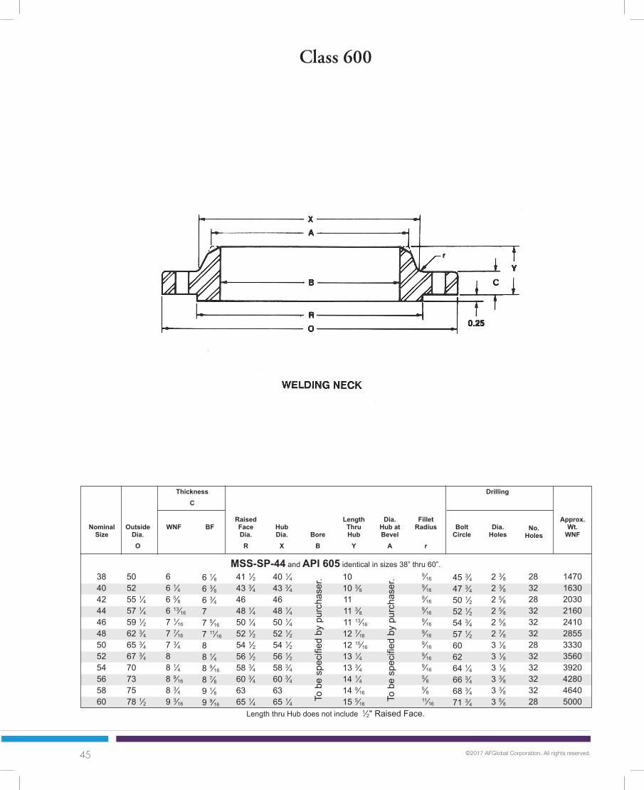
45 ©2017 AFGlobal Corporation. All rights reserved.
Class 600
NominalSize
50 52 55 1⁄4 57 1⁄4 59 1⁄2 62 3⁄4 65 3⁄4 67 3⁄4 70 73 75 78 1⁄2
OutsideDia.O
FilletRadius
r
RaisedFaceDia.R
Dia. Holes
Approx.Wt.
WNF
41 1⁄2 43 3⁄4 46 48 1⁄4 50 1⁄4 52 1⁄2 54 1⁄2 56 1⁄2 58 3⁄4 60 3⁄4 63 65 1⁄4
BoreB
384042444648505254565860
HubDia.
X
BoltCircle
WNF BF
To b
e sp
ecifi
ed b
y pu
rcha
ser. 6
6 1⁄4 6 5⁄8 6 13⁄16
7 1⁄16
7 7⁄16
7 3⁄4 8 8 1⁄4 8 9⁄16
8 3⁄4 9 3⁄16
ThicknessC
40 1⁄4 43 3⁄4 46 48 1⁄4 50 1⁄4 52 1⁄2 54 1⁄2 56 1⁄2 58 3⁄4 60 3⁄4 63 65 1⁄4
2 3⁄8 2 3⁄8 2 5⁄8 2 5⁄8 2 5⁄8 2 7⁄8 3 1⁄8 3 1⁄8 3 1⁄8 3 3⁄8 3 3⁄8 3 5⁄8
LengthThruHub
Y
Dia.Hub atBevel
A
No.Holes
To b
e sp
ecifi
ed b
y pu
rcha
ser. 10
10 3⁄8 11 11 3⁄8 11 13⁄16
12 7⁄16
12 15⁄16
13 1⁄4 13 3⁄4 14 1⁄4 14 9⁄16
15 5⁄16
9⁄16
9⁄16
9⁄16
9⁄16
9⁄16
9⁄16
9⁄16
9⁄16
9⁄16
5⁄8 5⁄8 11⁄16
147016302030216024102855333035603920428046405000
283228323232283232323228
45 3⁄4 47 3⁄4 50 1⁄2 52 1⁄2 54 3⁄4 57 1⁄2 60 62 64 1⁄4 66 3⁄4 68 3⁄4 71 3⁄4
Drilling
MSS-SP-44 and API 605 identical in sizes 38” thru 60”.
Length thru Hub does not include 1⁄2" Raised Face.
6 1⁄8 6 3⁄8 6 3⁄4 7 7 5⁄16
7 11⁄16
8 8 1⁄4 8 9⁄16
8 7⁄8 9 1⁄8 9 9⁄16

46 ©2017 AFGlobal Corporation. All rights reserved.
Class 900
NominalSize
42 3⁄4 46 48 1⁄2 51 3⁄4 55 57 1⁄2
40 1⁄4 43 1⁄2 46 1⁄2 48 3⁄4 51 3⁄4 53
OutsideDia.O
FilletRadius
r
RaisedFaceDia.R
Dia. Holes
Approx.Wt.
WNF
29 1⁄2 31 1⁄2 33 3⁄4 36 38 40 1⁄4
30 32 1⁄4 34 1⁄2 36 1⁄2 39 40 1⁄2
BoreB
262830323436
262830323436
HubDia.
X
BoltCircle
WNF BF
To b
e sp
ecifi
ed b
y pu
rcha
ser.
WELDING NECK
ThicknessC
30 1⁄2 32 3⁄4 35 37 1⁄4 39 5⁄8 41 7⁄8
29 1⁄4 31 3⁄8 33 1⁄2 35 3⁄4 37 7⁄8 40
2 7⁄8 3 1⁄8 3 1⁄8 3 3⁄8 3 5⁄8 3 5⁄8
2 5⁄8 2 7⁄8 3 1⁄8 3 1⁄8 3 3⁄8 3 1⁄8
LengthThruHub
Y
Dia.Hub atBevel
A
No.Holes
To b
e sp
ecifi
ed b
y pu
rcha
ser.
11 1⁄4 11 3⁄4 12 1⁄4 13 13 3⁄4 14 1⁄4
10 3⁄16
10 7⁄8 11 3⁄8 11 15⁄16
12 9⁄16
12 13⁄16
7⁄8 1⁄2 1⁄2 1⁄2 9⁄16
9⁄16
7⁄16
1⁄2 1⁄2 1⁄2 9⁄16
9⁄16
152518102120254529703395
105015201820206524502520
202020202020
202020202024
37 1⁄2 40 1⁄4 42 3⁄4 45 1⁄2 48 1⁄4 50 3⁄4
35 1⁄2 38 1⁄2 40 3⁄4 43 3⁄4 45 1⁄2 47 1⁄4
Drilling
5 1⁄2 5 5⁄8 5 7⁄8 6 1⁄4 6 1⁄2 6 3⁄4
5 5⁄16
5 13⁄16
6 1⁄8 6 5⁄16
6 3⁄4 6 13⁄16
MSS-SP-44 Sizes 12” thru 24” identical to ANSI B16.5 except when a single taper hub is required.
API 605*
Length thru Hub does not include 1⁄2" Raised Face.*Blind Flanges available upon request.
6 5⁄16
6 3⁄4 7 3⁄16
7 5⁄8 8 1⁄16
8 7⁄16
— — — — — —

47 ©2017 AFGlobal Corporation. All rights reserved.
Class 900
NominalSize
57 1⁄2 59 1⁄2 61 1⁄2 64 7⁄8 68 1⁄4 70 1⁄4
OutsideDia.O
FilletRadius
r
RaisedFaceDia.R
Dia. Holes
Approx.Wt.
WNF
43 1⁄4 45 3⁄4 47 3⁄4 50 52 1⁄2 54 1⁄2
BoreB
384042444648
HubDia.
X
BoltCircle
WNF BF
7 1⁄2 7 3⁄4 8 1⁄8 8 7⁄16
8 7⁄8 9 3⁄16
ThicknessC
42 1⁄4 44 3⁄8 46 5⁄16
48 5⁄8 50 7⁄8 52 7⁄8
3 5⁄8 3 5⁄8 3 5⁄8 3 7⁄8 4 1⁄8 4 1⁄8
LengthThruHub
Y
Dia.Hub atBevel
A
No.Holes
To b
e sp
ecifi
ed
by p
urch
aser
. 13 7⁄8 14 5⁄16
14 5⁄8 15 3⁄8 16 3⁄16
16 1⁄2
3⁄4 13⁄16
13⁄16
7⁄8 7⁄8 15⁄16
338536203960430046404980
202424242424
50 3⁄4 52 3⁄4 54 3⁄4 57 5⁄8 60 1⁄2 62 1⁄2
Drilling
MSS-SP-44 and API 605 identical in sizes 38” thru 48”.
Length thru Hub does not include 1⁄2" Raised Face.
8 1⁄2 8 13⁄16
9 1⁄8 9 9⁄16
10 1⁄16
10 3⁄8 To b
e sp
ecifi
ed
by p
urch
aser
.

48 ©2017 AFGlobal Corporation. All rights reserved.
Class 300, Welding Neck, Slip-On and Threaded
ANSI B16.36 Orifice Flanges
GENERAL NOTE: Dimensions are in inches.
NOTES:(1) Other NPT sizes may be furnished if required.(2) For slip-on and thread flanges, verify that TT drilling extends to inside diameter of pipe after assembly and is free from burrs.Weld neck flanges NPS 3 and smaller are identical to Class 600 flanges and may be so marked.All other dimensions are in accordance with ASME/ANSI B16.5.
NominalPipeSize
OutsideDia. ofFlange
O
Length Thru Hub
BackQB
WeldNeck
Y1
FaceQF
Hub Dia.Beginningof Chamfer
(W.N.)B1
Dia.of
Hub
Slip-Onand
ThreadedY2
Thicknessof
Flange Min.C
1 1⁄2 1 1⁄2 1 1⁄2 1 1⁄2 1 1⁄2 1 1⁄2 1 1⁄2 1 5⁄8 1 7⁄8 2 2 1⁄8 2 1⁄4 2 3⁄8 2 1⁄2 2 3⁄4
1 7⁄8 1 7⁄8 1 15⁄16
2 2 1⁄16
2 1⁄8 2 1⁄8 2 7⁄16
2 5⁄8 2 7⁄8 3 3 1⁄4 3 1⁄2 3 3⁄4 4 3⁄16
1.411.992.503.003.634.636.758.75
2 2 7⁄8 3 5⁄8 4 1⁄8 5 6 3⁄16
8 1⁄2 10 5⁄8 12 3⁄4 15 16 1⁄4 18 1⁄2 21 23 27 1⁄4
1.301.892.362.843.464.456.578.55
1.321.902.382.883.504.506.638.63
10.7512.7514.0016.0018.0020.0024.00
2 1⁄8 2 3⁄4 3 5⁄16
3 15⁄16
4 5⁄8 5 3⁄4 8 1⁄8 10 1⁄4 12 5⁄8 14 3⁄4 16 3⁄4 19 21 23 1⁄8 27 5⁄8
1 1 1⁄2 2 2 1⁄2 3 4 6 8 10 12 14 16 18 20 24
4 7⁄8 6 1⁄8 6 1⁄2 7 1⁄2 8 1⁄2 10 12 1⁄2 15 17 1⁄2 20 1⁄2 23 25 1⁄2 28 30 1⁄2 36
3 1⁄4 3 3⁄8 3 3⁄8 3 1⁄2 3 1⁄2 3 5⁄8 3 15⁄16
4 3⁄8 4 5⁄8 5 1⁄8 5 5⁄8 5 3⁄4 6 1⁄4 6 3⁄8 6 5⁄8
OutsideDia. of
Raised FaceR
Dia. ofCounterbore
See Note (8).

49 ©2017 AFGlobal Corporation. All rights reserved.
Class 300, Welding Neck, Slip-On and Threaded
ANSI B16.36 Orifice Flanges
NOTES:(5) Bolt lengths include allowance for orifice and gasket thickness of 0.25 in. for NPS 1-12 and 0.38 in. for NPS 14-24.(6) In conformance with ASME/ANSI B16.5, stud bolt lengths do not include point heights.(7) Bore diameter of weld neck flanges is to be specified by the purchaser.(8) Threaded flanges are furnished in NPS 1-8 only.
F G
Drilling Template
MachineBolts
BoltCircle
StudBolts
Dia. ofBolts
Dia. ofHoles
Dia. ofPressure
ConnectionTT
Slip-OnB2
1⁄4 1⁄4 1⁄4 1⁄4 3⁄8 1⁄2 1⁄2 1⁄2 1⁄2 1⁄2 1⁄2 1⁄2 1⁄2 1⁄2 1⁄2
11⁄16
13⁄16
11⁄16
13⁄16
13⁄16
13⁄16
7⁄8 1 1 1⁄8 1 1⁄4 1 1⁄4 1 3⁄8 1 3⁄8 1 3⁄8 1 5⁄8
3 1⁄2 4 1⁄2 5 5 7⁄8 6 5⁄8 7 7⁄8 10 5⁄8 13 15 1⁄4 17 3⁄4 20 1⁄4 22 1⁄2 24 3⁄4 27 32
Weld NeckB1
Bolt Length[(5), (6)]
No. ofHoles
1.441.471.501.751.811.881.882.19
Counterbore Depth(From Face)
Bore
0.750.720.690.560.560.560.310.44
See Note (8).
1.361.952.442.943.574.576.728.72
10.8812.8814.1416.1618.1820.2024.25
See
Not
e (7
).
448888
121216162020242424
5⁄8 3⁄4 5⁄8 3⁄4 3⁄4 3⁄4 3⁄4 7⁄8 1 1 1⁄8 1 1⁄8 1 1⁄4 1 1⁄4 1 1⁄4 1 1⁄2
4 1⁄2 4 3⁄4 4 1⁄2 4 3⁄4 4 3⁄4 4 3⁄4 4 3⁄4 5 5 3⁄4 6 1⁄4 6 1⁄2 7 7 1⁄4 7 1⁄2 8 1⁄4
5 5 1⁄4 5 5 1⁄4 5 1⁄4 5 1⁄4 5 1⁄4 5 3⁄4 6 1⁄2 7 7 1⁄4 7 3⁄4 8 8 1⁄2 9 1⁄2

50 ©2017 AFGlobal Corporation. All rights reserved.
Class 400, Welding Neck2
ANSI B16.36 Orifice Flanges
GENERAL NOTE: Dimensions are in inches.
NOTES:(1) Other NPT sizes may be furnished if required.(2) All other dimensions are in accordance with ASME/ANSI B16.5.(3) In conformance with ASME/ANSI B16.5, stud bolt lengths do not include point heights.
NominalPipeSize
OutsideDia. ofFlange
O
Radiusat Bottom
rmax
GrooveNumber
SpecialOval Ring
HeightW
GrooveWidth
F
LengthThruHub
Y
Thicknessof
Flange Min.C
1 1⁄2 1 5⁄8 1 7⁄8 2 1⁄8 2 1⁄4 2 25⁄64
2 1⁄2 2 5⁄8 2 3⁄4 3
3 1⁄2 4 1⁄16
4 5⁄8 4 7⁄8 5 3⁄8 5 7⁄8 6 6 1⁄2 6 5⁄8 6 7⁄8
0.030.030.030.030.030.030.030.030.06
6 3⁄16
8 1⁄2 10 5⁄8 12 3⁄4 15 16 1⁄4 18 1⁄2 21 23 27 1⁄4
1.061.061.061.061.061.061.191.191.25
0.4690.4690.4690.4690.4690.4690.4690.4690.531
1 1 1⁄2 2 2 1⁄2 3 4 6 8 10 12 14 16 18 20 24
10 12 1⁄2 15 17 1⁄2 20 1⁄2 23 25 1⁄2 28 30 1⁄2 36
OutsideDia. of
Raised FaceR
Ring Type Joint
See Note (6).
PitchDia.
P
GrooveDepth
E
R37R45R49R53R57R61R65R69R73
5.8758.312
10.62512.75015.00016.50018.50021.00023.000
0.3120.3120.3120.3120.3120.3120.3120.3120.312
For NPS 3 and smaller, use Class 600.

51 ©2017 AFGlobal Corporation. All rights reserved.
Class 400, Welding Neck2
ANSI B16.36 Orifice Flanges
(4) Bolt lengths for raised face flanges include allowance for orifice and gasket thickness of 0.25 in. for NPS 4-12 and 0.38 in. for NPS 14-24. Bolt lengths for ring type joint flanges include allowance of 0.62 in. for NPS -10, 0.75 for NPS 12-18, and 0.88 in. for NPS 20.(5) Bore is to be specified by purchaser.(6) Ring joint flange is not shown in NPS 24 due to insufficient metal between groove and pressure tap hole.(7) All Texas Metal Works RTJ orifice flanges are 0.94 pressure tap center.
Dia.of
HubX
Hub Dia.Beginningof Chamfer
A
Drilling Template
RaisedFace
No.of
HolesRingJoint
Dia.of
Bolts
Dia.of
Holes
Dia.of
BoltCircle
BoreB
7 7⁄8 10 5⁄8 13 15 1⁄4 17 3⁄4 20 1⁄4 22 1⁄2 24 3⁄4 27 32
1⁄21⁄21⁄21⁄21⁄21⁄21⁄21⁄21⁄21⁄2
1 1 1 1⁄8 1 1⁄4 1 3⁄8 1 3⁄8 1 1⁄2 1 1⁄2 1 5⁄8 1 57⁄64
Dia. ofPressure
ConnectionTT
Length of Stud Bolts[(3), (4)]
5 3⁄4 8 1⁄8 10 1⁄4 12 5⁄8 14 3⁄4 16 3⁄4 19 21 23 1⁄8 23 5⁄8
4.506.638.63
10.7512.7514.0016.0018.0020.0024.00
See
Not
e (5
).
8121216162020242424
7⁄8 7⁄8 1 1 1⁄8 1 1⁄4 1 1⁄4 1 3⁄8 1 1⁄2 1 1⁄2 1 3⁄4
5 1⁄2 6 1⁄4 6 3⁄4 7 1⁄2 8 8 1⁄4 8 3⁄4 9 1⁄4 9 3⁄4 11
6 6 1⁄2 7 1⁄4 8 8 1⁄2 9 9 1⁄4 9 1⁄2 10 1⁄4 —
For NPS 3 and smaller, use Class 600.

52 ©2017 AFGlobal Corporation. All rights reserved.
Class 600, Welding Neck 2, 3
ANSI B16.36 Orifice Flanges
GENERAL NOTE: Dimensions are in inches.
NOTES:(1) Other NPT sizes may be furnished if required.(2) Weldneck flanges NPS 3 and smaller are identical to Class 300 flanges except for bolting and may be used for such service.(3) All other dimensions are in accordance with ASME/ANSI B16.5.(4) 0.06 in. height of raised face in NPS 1-3 is included in dimensions C and Y.
NominalPipeSize
OutsideDia. ofFlange
O
Radiusat Bottom
rmax
GrooveNumber
SpecialOval Ring
HeightW
GrooveWidth
F
LengthThruHub
Y
Thicknessof Flange (4)
Min.C
1 1⁄2 1 1⁄2 1 1⁄2 1 1⁄2 1 1⁄2 1 1⁄2 1 7⁄8 2 3⁄16 2 1⁄2 2 5⁄8 2 3⁄4 3 3 1⁄4 3 1⁄2 4
3 1⁄4 3 3⁄8 3 3⁄8 3 1⁄2 3 1⁄2 4 4 5⁄8 5 1⁄4 6 6 1⁄8 6 1⁄2 7 7 1⁄4 7 1⁄2 8
0.030.030.030.030.030.030.030.030.030.030.030.030.030.06
2 2 7⁄8 3 5⁄8 4 1⁄8 5 6 3⁄16
8 1⁄2 10 5⁄8 12 3⁄4 15 16 1⁄4 18 1⁄2 21 23 27 1⁄4
1.001.001.061.061.061.061.061.061.061.061.061.191.191.25
0.2500.2500.3120.3120.3120.3120.3120.3120.3120.3120.3120.3120.3120.375
1 1 1⁄2 2 2 1⁄2 3 4 6 8 10 12 14 16 18 20 24
4 7⁄8 6 1⁄8 6 1⁄2 7 1⁄2 8 1⁄4 10 3⁄4 14 16 1⁄2 20 22 23 3⁄4 27 29 1⁄4 32 37
OutsideDia. of
Raised FaceR
Ring Type Joint
See Note (8).
PitchDia.
P
GrooveDepth
E
0.060.060.060.060.060.250.250.250.250.250.250.250.250.250.25
R16R20R23R26R31R37R45R49R53R57R61R65R69R73
2.0002.6883.2504.0004.8755.8758.312
10.62512.75015.00016.50018.50021.00023.000
Height ofRaisedFace
H
0.3440.3440.4690.4690.4690.4690.4690.4690.4690.4690.4690.4690.4690.531

53 ©2017 AFGlobal Corporation. All rights reserved.
Class 600, Welding Neck 2, 3
ANSI B16.36 Orifice Flanges
(5) Bolt lengths for raised face flanges include allowance for orifice and gasket thickness of 0.25 in. for NPS 1-12 and 0.38 in. for NPS 14-24. Bolt lengths for ring type joint flanges include allowance of 0.62 in. for NPS 1-10, 0.75 for NPS 12-18, and 0.88 in. for NPS 20.(6) In conformance with ASME/ANSI B16.5, stud bolt lengths do not include point heights.(7) Bore is to be specified by purchaser.(8) Ring joint flange is not shown in NPS 24 due to insufficient metal between groove and pressure tap hole.(9) All Texas Metal Works RTJ orifice flanges are 0.94 pressure tap center.
Dia.of
HubX
Hub Dia.Beginningof Chamfer
A
Drilling Template
RaisedFace
No.of
HolesRingJoint
Dia.of
Bolts
Dia. of HolesDia.of
BoltCircle
BoreB
3 1⁄2 4 1⁄2 5 5 7⁄8 6 5⁄8 8 1⁄2 11 1⁄2 13 3⁄4 17 19 1⁄4 20 3⁄4 23 3⁄4 25 3⁄4 28 1⁄2 33
1⁄41⁄41⁄41⁄43⁄81⁄21⁄21⁄21⁄21⁄21⁄21⁄21⁄21⁄21⁄2
11⁄16 13⁄16 11⁄16 13⁄16 13⁄16
1 1 1⁄8 1 1⁄4 1 3⁄8 1 3⁄8 1 1⁄2 1 5⁄8 1 3⁄4 1 3⁄4 2
Dia. ofPressure
ConnectionTT
Length of Stud Bolts[(5), (6)]
2 1⁄8 2 3⁄4 3 5⁄16
3 15⁄16
4 5⁄8 6 8 3⁄4 10 3⁄4 13 1⁄2 15 3⁄4 17 19 1⁄2 21 1⁄2 24 28 1⁄4
1.321.902.382.883.504.506.638.63
10.7512.7514.0016.0018.0020.0024.00
See
Not
e (7
).
448888
121216162020242424
5⁄8 3⁄4 5⁄8 3⁄4 3⁄4 7⁄8 1 1 1⁄8 1 1⁄4 1 1⁄4 1 3⁄8 1 1⁄2 1 5⁄8 1 5⁄8 1 7⁄8
5 5 1⁄4 5 5 1⁄4 5 1⁄4 6 7 7 3⁄4 8 3⁄4 9 9 1⁄2 10 1⁄4 11 11 3⁄4 13 1⁄4
1 1 1⁄2 2 2 1⁄2 3 4 6 8 10 12 14 16 18 20 24
RaisedFace
RingJoint
NominalPipeSize
3⁄4 7⁄8 3⁄4 7⁄8 7⁄8 1 1 1⁄8 1 1⁄4 1 3⁄8 1 3⁄8 1 1⁄2 1 5⁄8 1 3⁄4 1 3⁄4 2
5 1⁄2 5 1⁄2 5 1⁄2 5 3⁄4 5 1⁄4 6 1⁄2 7 1⁄2 8 1⁄4 9 1⁄4 9 1⁄2 10 10 3⁄4 11 1⁄2 12 1⁄2 —
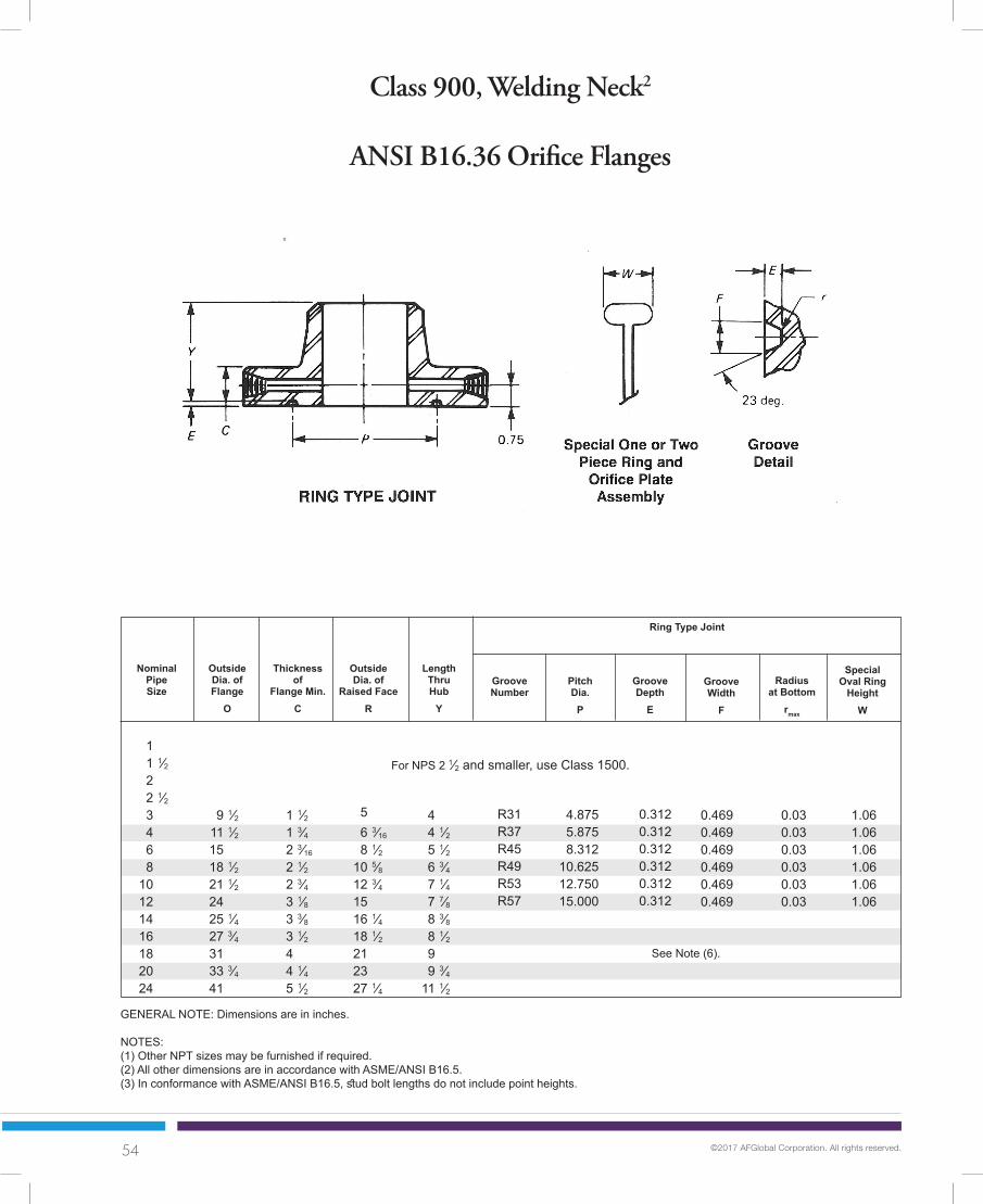
54 ©2017 AFGlobal Corporation. All rights reserved.
Class 900, Welding Neck2
ANSI B16.36 Orifice Flanges
GENERAL NOTE: Dimensions are in inches.
NOTES:(1) Other NPT sizes may be furnished if required.(2) All other dimensions are in accordance with ASME/ANSI B16.5.(3) In conformance with ASME/ANSI B16.5, stud bolt lengths do not include point heights.
NominalPipeSize
OutsideDia. ofFlange
O
Radiusat Bottom
rmax
GrooveNumber
SpecialOval Ring
HeightW
GrooveWidth
F
LengthThruHub
Y
Thicknessof
Flange Min.C
1 1⁄2 1 3⁄4 2 3⁄16
2 1⁄2 2 3⁄4 3 1⁄8 3 3⁄8 3 1⁄2 4 4 1⁄4 5 1⁄2
4 4 1⁄2 5 1⁄2 6 3⁄4 7 1⁄4 7 7⁄8 8 3⁄8 8 1⁄2 9 9 3⁄4 11 1⁄2
0.030.030.030.030.030.03
5 6 3⁄16
8 1⁄2 10 5⁄8 12 3⁄4 15 16 1⁄4 18 1⁄2 21 23 27 1⁄4
1.061.061.061.061.061.06
0.4690.4690.4690.4690.4690.469
1 1 1⁄2 2 2 1⁄2 3 4 6 8 10 12 14 16 18 20 24
9 1⁄2 11 1⁄2 15 18 1⁄2 21 1⁄2 24 25 1⁄4 27 3⁄4 31 33 3⁄4 41
OutsideDia. of
Raised FaceR
Ring Type Joint
See Note (6).
PitchDia.
P
GrooveDepth
E
R31R37R45R49R53R57
4.8755.8758.312
10.62512.75015.000
0.3120.3120.3120.3120.3120.312
For NPS 2 1⁄2 and smaller, use Class 1500.

55 ©2017 AFGlobal Corporation. All rights reserved.
Class 900, Welding Neck2
ANSI B16.36 Orifice Flanges
(4) Bolt lengths for raised face flanges include allowance for orifice and gasket thickness of 0.25 in. for NPS 3-12 and 0.38 in. for NPS 14-24. Bolt lengths for ring type joint flanges include allowance of 0.62 in. for NPS 3-10, 0.75 for NPS 12-18, and 0.75 in. for NPS 12.(5) Bore is to be specified by purchaser.(6) Ring joint flanges larger than 12 are not shown due to insufficient metal between groove and pressure tap hole.(7) All Texas Metal Works RTJ orifice flanges are 0.94 pressure tap center.
Dia.of
HubX
Hub Dia.Beginningof Chamfer
A
Drilling Template
RaisedFace
No.of
HolesRingJoint
Dia.of
Bolts
Dia.of
Holes
Dia.of
BoltCircle
BoreB
7 1⁄2 9 1⁄4 12 1⁄2 15 1⁄2 18 1⁄2 21 22 24 1⁄4 27 29 1⁄2 35 1⁄2
3⁄81⁄21⁄21⁄21⁄21⁄21⁄21⁄21⁄21⁄21⁄2
1 1 1⁄4 1 1⁄4 1 1⁄2 1 1⁄2 1 1⁄2 1 5⁄8 1 3⁄4 2 2 1⁄8 2 5⁄8
Dia. ofPressure
ConnectionTT
Length of Stud Bolts[(3), (4)]
5 6 1⁄4 9 1⁄4 11 3⁄4 14 1⁄2 16 1⁄2 17 3⁄4 20 22 1⁄4 24 1⁄2 29 1⁄2
3.504.506.638.63
10.7512.7514.0016.0018.0020.0024.00
See
Not
e (5
).
88
121216202020202020
7⁄8 1 1⁄8 1 1⁄8 1 3⁄8 1 3⁄8 1 3⁄8 1 1⁄2 1 5⁄8 1 7⁄8 2 2 1⁄2
6 7 7 3⁄4 9 9 1⁄2 10 1⁄4 11 11 1⁄2 13 14 17 1⁄2
6 1⁄2 7 1⁄2 8 1⁄4 8 1⁄2 10 10 3⁄4 — — — — —
For NPS 2 1⁄2 and smaller, use Class 1500.

56 ©2017 AFGlobal Corporation. All rights reserved.
Class 1500, Welding Neck2
ANSI B16.36 Orifice Flanges
GENERAL NOTE: Dimensions are in inches.
NOTES:(1) Other NPT sizes may be furnished if required.(2) All other dimensions are in accordance with ASME/ANSI B16.5.(3) In conformance with ASME/ANSI B16.5, stud bolt lengths do not include point heights.
NominalPipeSize
OutsideDia. ofFlange
O
Radiusat Bottom
rmax
GrooveNumber
SpecialOval Ring
HeightW
GrooveWidth
F
LengthThruHub
Y
Thicknessof
Flange Min.C
1 1⁄2 1 1⁄2 1 1⁄2 1 5⁄8 1 7⁄8 2 1⁄8 3 1⁄4 3 5⁄8 4 1⁄4 4 7⁄8 5 1⁄4 5 3⁄4 6 3⁄8 7 8
3 1⁄4 3 1⁄2 4 4 1⁄8 4 5⁄8 4 7⁄8 6 3⁄4 8 3⁄8 10 11 1⁄8 11 3⁄4 12 1⁄4 12 7⁄8 14 16
0.030.030.030.030.030.030.06
2 2 7⁄8 3 5⁄8 4 1⁄8 5 6 3⁄16
8 1⁄2 10 5⁄8 12 3⁄4 15 16 1⁄4 18 1⁄2 21 23 27 1⁄4
1.001.001.061.061.061.061.12
0.3440.3440.4690.4690.4690.4690.531
1 1 1⁄2 2 2 1⁄2 3 4 6 8 10 12 14 16 18 20 24
5 7⁄8 7 8 1⁄2 9 5⁄8 11 1⁄2 12 1⁄4 15 1⁄2 19 23 26 1⁄2 29 1⁄2 32 1⁄2 36 38 3⁄4 46
OutsideDia. of
Raised FaceR
Ring Type Joint
See Note (6).
PitchDia.
P
GrooveDepth
E
R16R20R24R27R35R39R46
2.0002.6883.7504.2505.3756.3758.312
0.2500.2500.3120.3120.3120.3120.375

57 ©2017 AFGlobal Corporation. All rights reserved.
Class 1500, Welding Neck2
ANSI B16.36 Orifice Flanges
(4) Bolt lengths for raised face flanges include allowance for orifice and gasket thickness of 0.25 in. for NPS 1-12 and 0.38 in. for NPS 14-24. Bolt lengths for ring type joint flanges include allowance of 0.62 in. for NPS 1-6.(5) Bore is to be specified by purchaser.(6) Ring joint flanges larger than NPS 6 are not shown due to insufficient metal between groove and pressure tap hole.(7) All Texas Metal Works RTJ orifice flanges are 0.94 pressure tap center.
Dia.of
HubX
Hub Dia.Beginningof Chamfer
A
Drilling Template
RaisedFace
No.of
HolesRingJoint
Dia.of
Bolts
Dia.of
Holes
Dia.of
BoltCircle
BoreB
4 4 7⁄8 6 1⁄2 7 1⁄2 8 9 1⁄2 12 1⁄2 15 1⁄2 19 22 1⁄2 25 27 3⁄4 30 1⁄2 32 3⁄4 39
1⁄41⁄41⁄41⁄43⁄81⁄21⁄21⁄21⁄21⁄21⁄21⁄21⁄21⁄21⁄2
1 1 1⁄8 1 1 1⁄8 1 1⁄4 1 3⁄8 1 1⁄2 1 3⁄4 2 2 1⁄8 2 3⁄8 2 5⁄8 2 7⁄8 3 1⁄8 3 5⁄8
Dia. ofPressure
ConnectionTT
Length of Stud Bolts[(3), (4)]
2 1⁄16
2 3⁄4 4 1⁄8 4 7⁄8 5 1⁄4 6 3⁄8 9 11 1⁄2 14 1⁄2 17 3⁄4 19 1⁄2 21 3⁄4 23 1⁄2 25 1⁄5 30
1.321.902.382.883.504.506.638.63
10.7512.7514.0016.0018.0020.0024.00
See
Not
e (5
).
448888
121212161616161616
7⁄8 1 7⁄8 1 1 1⁄8 1 1⁄4 1 3⁄8 1 5⁄8 1 7⁄8 2 2 1⁄4 2 1⁄2 2 3⁄4 3 3 1⁄2
6 6 1⁄4 6 6 1⁄2 7 1⁄4 8 10 1⁄2 11 3⁄4 13 1⁄2 15 16 1⁄4 17 3⁄4 19 3⁄4 21 1⁄2 24 1⁄2
6 1⁄4 6 1⁄2 6 1⁄2 7 7 1⁄4 8 1⁄2 11 — — — — — — — —

58 ©2017 AFGlobal Corporation. All rights reserved.
Class 2500, Welding Neck2
ANSI B16.36 Orifice Flanges
GENERAL NOTE: Dimensions are in inches.
NOTES:(1) Other NPT sizes may be furnished if required.(2) All other dimensions are in accordance with ASME/ANSI B16.5.(3) In conformance with ASME/ANSI B16.5, stud bolt lengths do not include point heights.
NominalPipeSize
OutsideDia. ofFlange
O
Radiusat Bottom
rmax
GrooveNumber
SpecialOval Ring
HeightW
GrooveWidth
F
LengthThruHub
Y
Thicknessof
Flange Min.C
1 1⁄2 1 3⁄4 2 2 1⁄4 2 5⁄8 3 4 1⁄4 5 6 1⁄2 7 1⁄4
3 5⁄8 4 3⁄8 5 5 5⁄8 6 5⁄8 7 1⁄2 10 3⁄4 12 1⁄2 16 1⁄2 18 1⁄4
0.030.030.030.060.06
2 2 7⁄8 3 5⁄8 4 1⁄8 5 6 3⁄16
8 1⁄2 10 5⁄8 12 3⁄4 15
1.001.061.061.191.19
0.3440.4690.4690.5310.531
1 1 1⁄2 2 2 1⁄2 3 4 6 8 10 12
6 1⁄4 8 9 1⁄4 10 1⁄2 12 14 19 21 3⁄4 26 1⁄2 30
OutsideDia. of
Raised FaceR
Ring Type Joint
See Note (6).
PitchDia.
P
GrooveDepth
E
R18R23R26R28R32
2.3753.2504.0004.3755.000
0.2500.3120.3120.3750.375

59 ©2017 AFGlobal Corporation. All rights reserved.
Class 2500, Welding Neck2
ANSI B16.36 Orifice Flanges
(4) Bolt lengths for raised face flanges include allowance for orifice and gasket thickness of 0.25 in. for NPS 1-12. Bolt lengths for ring type joint flanges include allowance of 0.62 in. for NPS 1-3.(5) Bore is to be specified by purchaser.(6) Ring joint flanges larger than NPS 3 are not shown due to insufficient metal between groove and pressure tap hole.(7) All Texas Metal Works RTJ orifice flanges are 0.94 pressure tap center.
Dia.of
HubX
Hub Dia.Beginningof Chamfer
A
Drilling Template
RaisedFace
No.of
HolesRingJoint
Dia.of
Bolts
Dia.of
Holes
Dia.of
BoltCircle
BoreB
4 1⁄4 5 3⁄4 6 3⁄4 7 3⁄4 9 10 3⁄4 14 1⁄2 17 1⁄4 21 1⁄4 24 3⁄8
1⁄41⁄41⁄41⁄43⁄81⁄21⁄21⁄21⁄21⁄2
1 1 1⁄4 1 1⁄8 1 1⁄4 1 3⁄8 1 5⁄8 2 1⁄8 2 1⁄8 2 5⁄8 2 7⁄8
Dia. ofPressure
ConnectionTT
Length of Stud Bolts[(3), (4)]
2 1⁄4 3 1⁄8 3 3⁄4 4 1⁄2 5 1⁄4 6 1⁄2 9 1⁄4 12 14 3⁄4 17 3⁄8
1.321.902.382.883.504.506.638.63
10.7512.75
See
Not
e (5
).
4488888
121212
7⁄8 1 1⁄8 1 1 1⁄8 1 1⁄4 1 1⁄2 2 2 2 1⁄2 2 3⁄4
6 7 7 1⁄4 8 9 10 1⁄4 13 3⁄4 15 1⁄4 19 1⁄4 21 1⁄4
6 1⁄4 7 1⁄2 7 3⁄4 8 1⁄2 9 1⁄2 — — — — —

60 ©2017 AFGlobal Corporation. All rights reserved.
Typical Facings
For Steel Pipe Flanges
See Dimensions and Notes

61 ©2017 AFGlobal Corporation. All rights reserved.
Facing Dimensions For Ring Joints
ANSI B16.5
DIMENSIONS are shown in inches, and conform to ASA Specification B 16.5, and API 5-G3.
RING JOINT flanges will be furnished in accordance with these details, unless otherwise specified by the purchaser. Lap joint stubs will also conform to these dimensions, except where designed for use with 3”,
300, 400 & 600 lb. flances (such lap joint stubs will be made for Ring No. R30: pitch diameter 4 5⁄8").
DEPTH of groove is added to flange thickness except that on sizes marked (*), the groove will cut 1⁄32" into the minimum flange thickness.
NominalPipeSize
Pitch Dia.of Ring
and GrooveP
Groove
Height ofOval Ring
BDepth
L
Approx. Distance Between Flanges
When Joint is Compressed
WidthA
RingNo.Width
D
Dia. ofRaisedFace
K
*1⁄4*1⁄4*1⁄41⁄41⁄41⁄41⁄41⁄41⁄41⁄41⁄41⁄41⁄41⁄41⁄41⁄41⁄41⁄4
1 1 1⁄4 1 1⁄2 2 2 1⁄2 3 3 1⁄2 4 5 6 8 10 12 14 16 18 20 24
R15R17R19R22R25R29R33R36R40R43R48R52R56R59R64R68R72R76
Ring
For 150 LB. Flanges
1 7⁄8 2 1⁄4 2 9⁄16
3 1⁄4 4 4 1⁄2 5 3⁄16
5 7⁄8 6 3⁄4 7 5⁄8 9 3⁄4 12 15 15 5⁄8 17 7⁄8 20 3⁄8 22 26 1⁄2
11⁄3211⁄3211⁄3211⁄3211⁄3211⁄3211⁄3211⁄3211⁄3211⁄3211⁄3211⁄3211⁄3211⁄3211⁄3211⁄3211⁄3211⁄32
2 1⁄2 2 7⁄8 3 1⁄4 4 4 3⁄4 5 1⁄4 6 1⁄16
6 3⁄4 7 5⁄8 8 5⁄8 10 3⁄4 13 16 16 3⁄4 19 21 1⁄2 23 1⁄2 28
5⁄165⁄165⁄165⁄165⁄165⁄165⁄165⁄165⁄165⁄165⁄165⁄165⁄165⁄165⁄165⁄165⁄165⁄16
9⁄169⁄169⁄169⁄169⁄169⁄169⁄169⁄169⁄169⁄169⁄169⁄169⁄169⁄169⁄169⁄169⁄169⁄16
5⁄325⁄325⁄325⁄325⁄325⁄325⁄325⁄325⁄325⁄325⁄325⁄325⁄321⁄81⁄81⁄81⁄81⁄8

62 ©2017 AFGlobal Corporation. All rights reserved.
Facing Dimensions For Ring Joints
ANSI B16.5
DIMENSIONS are shown in inches, and conform to ASA Specification B 16.5, and API 5-G3.
RING JOINT flanges will be furnished in accordance with these details, unless otherwise specified by the purchaser. Lap joint stubs will also conform to these dimensions, except where designed for use with 3”,
300, 400 & 600 lb. flances (such lap joint stubs will be made for Ring No. R30: pitch diameter 4 5⁄8").
DEPTH of groove is added to flange thickness except that on sizes marked (*), the groove will cut 1⁄32" into the minimum flange thickness.
NominalPipeSize
Pitch Dia.of Ring
and GrooveP
Groove
OvalB
DepthL
Approx. Distance Between Flanges
When Joint is Compressed
300 lb. 400 lb. 600 lbWidth
A
RingNumberWidth
D
Dia. ofRaisedFace
K
*7⁄32*1⁄4*1⁄4*1⁄4*1⁄45⁄165⁄165⁄165⁄165⁄165⁄165⁄165⁄165⁄165⁄165⁄165⁄165⁄16
3⁄87⁄16
1 11⁄32
1 11⁄16
2 2 3⁄8 2 11⁄16
3 1⁄4 4 4 7⁄8 5 3⁄16
5 7⁄8 7 1⁄8 8 5⁄16
10 5⁄8 12 3⁄4 15 16 1⁄2 18 1⁄2 21 23 27 1⁄4
R11R13R16R18R20R23R26R31R34R37R41R45R49R53R57R61R65R69R73R77
Ring
For 300, 400 and 600 LB. Flanges
9⁄3211⁄3211⁄3211⁄3211⁄3215⁄3215⁄3215⁄3215⁄3215⁄3215⁄3215⁄3215⁄3215⁄3215⁄3215⁄3215⁄3215⁄3217⁄3221⁄32
2 2 1⁄2 2 3⁄4 3 1⁄8 3 9⁄16
4 1⁄4 5 5 3⁄4 6 1⁄4 6 7⁄8 8 1⁄4 9 1⁄2 11 7⁄8 14 16 1⁄4 18 20 22 5⁄8 25 29 1⁄2
1⁄45⁄165⁄165⁄165⁄167⁄167⁄167⁄167⁄167⁄167⁄167⁄167⁄167⁄167⁄167⁄167⁄167⁄161⁄25⁄8
7⁄169⁄169⁄169⁄169⁄16
11⁄1611⁄1611⁄1611⁄1611⁄1611⁄1611⁄1611⁄1611⁄1611⁄1611⁄1611⁄1611⁄16
3⁄47⁄8
1⁄85⁄325⁄325⁄325⁄327⁄327⁄327⁄327⁄327⁄327⁄327⁄327⁄327⁄327⁄327⁄327⁄327⁄327⁄321⁄4
Octag.H
Height ofFlat on
Oct. RingC
3⁄81⁄21⁄21⁄21⁄25⁄85⁄85⁄85⁄85⁄85⁄85⁄85⁄85⁄85⁄85⁄85⁄85⁄8
11⁄1613⁄16
5⁄165⁄16
1⁄2 3⁄4 1 1 1⁄4 1 1⁄2 2 2 1⁄2 3 3 1⁄2 4 5 6 8 10 12 14 16 18 20 24
1⁄85⁄325⁄325⁄325⁄323⁄163⁄163⁄163⁄167⁄327⁄327⁄327⁄327⁄327⁄327⁄327⁄327⁄327⁄321⁄4
1⁄85⁄325⁄325⁄325⁄323⁄163⁄163⁄163⁄163⁄163⁄163⁄163⁄163⁄163⁄163⁄163⁄163⁄163⁄167⁄32
Height

63 ©2017 AFGlobal Corporation. All rights reserved.
Facing Dimensions For Ring Joints
ANSI B16.5
CORNER RADIUS “r” is 1⁄32" for ring width 7⁄16" and smaller; 1⁄16" for ring widths 1⁄2" to 7⁄8" inclusive and 3⁄32" for ring widths 1” and larger.
FLAT-BOTTOMED GROOVE, as shown in detail above, will be furnished unless otherwise specified.
TOLERANCES: P ± .005" B ± 1⁄64" H ± 1⁄64"" A ± .008" D ± 1⁄64" L ± 1⁄64”"
NominalPipeSize
Pitch Dia.of Ring
and GrooveP
Groove
OvalB
DepthL
WidthA
RingNumberWidth
D
Dia. ofRaisedFace
K
*7⁄32*1⁄4*1⁄4*1⁄4*1⁄45⁄165⁄165⁄165⁄165⁄165⁄165⁄165⁄165⁄167⁄167⁄16
1⁄21⁄25⁄8
1 9⁄16
1 3⁄4 2 2 3⁄8 2 11⁄16
3 3⁄4 4 1⁄4 4 7⁄8 5 7⁄8 7 1⁄8 8 5⁄16
10 5⁄8 12 3⁄4 15 16 1⁄2 18 1⁄2 21 23 27 1⁄4
R12R14R16R18R20R24R27R31R37R41R45R49R53R57R62R66R70R74R78
Ring
For 900 LB. Flanges
11⁄3211⁄3211⁄3211⁄3211⁄3215⁄3215⁄3215⁄3215⁄3215⁄3215⁄3215⁄3215⁄3215⁄3221⁄3221⁄3225⁄3225⁄32
1 1⁄6
2 3⁄8 2 5⁄8 2 13⁄16
3 3⁄16
3 5⁄8 4 7⁄8 5 3⁄8 6 1⁄8 7 1⁄8 8 1⁄2 9 1⁄2 12 1⁄8 14 1⁄4 16 1⁄2 18 3⁄8 20 5⁄8 23 3⁄8 25 1⁄2 30 3⁄8
5⁄16 5⁄16 5⁄16 5⁄16 5⁄16 7⁄16 7⁄16 7⁄16 7⁄16 7⁄16 7⁄16 7⁄16 7⁄16 7⁄16 5⁄8 5⁄8 3⁄4 3⁄4 1
9⁄16 9⁄16 9⁄16 9⁄16 9⁄16 11⁄16 11⁄16 11⁄16 11⁄16 11⁄16 11⁄16 11⁄16 11⁄16 11⁄16 7⁄8 7⁄8 1
1 1 5⁄16
Octag.H
Height ofFlat on
Oct. RingC
5⁄8 5⁄8 5⁄8 5⁄8 5⁄8 5⁄8 5⁄8 13⁄16 13⁄16 15⁄16 15⁄16
1 5⁄16
5⁄165⁄165⁄165⁄161⁄2
1⁄2 3⁄4 1 1 1⁄4 1 1⁄2 2 2 1⁄2 3 4 5 6 8 10 12 14 16 18 20 24
5⁄325⁄325⁄325⁄325⁄321⁄81⁄85⁄325⁄325⁄325⁄325⁄325⁄325⁄325⁄325⁄323⁄163⁄167⁄32
Approx. Distance Between Flanges
When Joint is Compressed
Height
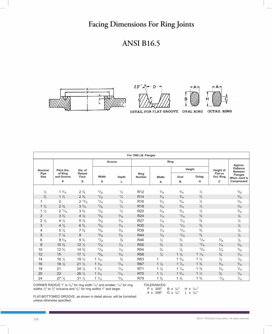
64 ©2017 AFGlobal Corporation. All rights reserved.
Facing Dimensions For Ring Joints
ANSI B16.5
NominalPipeSize
Pitch Dia.of Ring
and GrooveP
Groove
OvalB
DepthL
WidthA
RingNumberWidth
D
Dia. ofRaisedFace
K
*1⁄4*1⁄4*1⁄4*1⁄4*1⁄45⁄165⁄165⁄165⁄165⁄16
3⁄87⁄167⁄169⁄16
5⁄811⁄1611⁄1611⁄1613⁄16
1 9⁄16
1 3⁄4 2 2 3⁄8 2 11⁄16
3 3⁄4 4 1⁄4 4 7⁄8 5 7⁄8 7 1⁄8 8 5⁄16
10 5⁄8 12 3⁄4 15 16 1⁄2 18 1⁄2 21 23 27 1⁄4
R12R14R16R18R20R24R27R35R39R44R46R50R54R58R63R67R71R75R79
Ring
For 1500 LB. Flanges
11⁄32 11⁄32 11⁄32 11⁄32 11⁄32 15⁄32 15⁄32 15⁄32 15⁄32 15⁄32 17⁄32 21⁄32 21⁄32 29⁄32
1 1⁄16
1 3⁄16
1 3⁄16
1 5⁄16
1 7⁄16
2 3⁄8 2 5⁄8 2 13⁄16
3 3⁄16
3 5⁄8 4 7⁄8 5 3⁄8 6 5⁄8 7 5⁄8 9 9 3⁄4 12 1⁄2 14 5⁄8 17 1⁄4 19 1⁄4 21 1⁄2 24 1⁄8 26 1⁄2 31 1⁄4
5⁄16 5⁄16 5⁄16 5⁄16 5⁄16 7⁄16 7⁄16 7⁄16 7⁄16 7⁄16 1⁄2 5⁄8 5⁄8 7⁄8 1 1 1⁄8
1 1⁄8
1 1⁄4 1 3⁄8
9⁄16 9⁄16 9⁄16 9⁄16 9⁄16 11⁄16 11⁄16 11⁄16 11⁄16 11⁄16 3⁄4 7⁄8 7⁄8 1 1⁄8 1 5⁄16
1 7⁄10
1 7⁄16
1 9⁄16
1 3⁄4
Octag.H
Height ofFlat on
Oct. RingC
5⁄16 5⁄16 5⁄16 3⁄8 1⁄2 9⁄16 9⁄16 5⁄8 11⁄16
1⁄2 3⁄4 1 1 1⁄4 1 1⁄2 2 2 1⁄2 3 4 5 6 8 10 12 14 16 18 20 24
5⁄325⁄325⁄325⁄325⁄321⁄81⁄81⁄81⁄81⁄81⁄85⁄325⁄323⁄167⁄325⁄165⁄163⁄167⁄16
Approx. Distance Between Flanges
When Joint is Compressed
Height
CORNER RADIUS “r” is 1⁄32" for ring width 7⁄16" and smaller; 1⁄16" for ring widths 1⁄2" to 7⁄8" inclusive and 3⁄32" for ring widths 1” and larger.
FLAT-BOTTOMED GROOVE, as shown in detail above, will be furnished unless otherwise specified.
TOLERANCES: P ± .005" B ± 1⁄64" H ± 1⁄64"" A ± .008" D ± 1⁄64" L ± 1⁄64”"
1⁄2 1⁄2 1⁄2 1⁄2 1⁄2 5⁄8 5⁄8 5⁄8 5⁄8 5⁄8 11⁄16 13⁄16 13⁄16
1 1⁄16
1 1⁄4 1 3⁄8 1 3⁄8 1 1⁄2 1 5⁄8

65 ©2017 AFGlobal Corporation. All rights reserved.
Facing Dimensions For Ring Joints
ANSI B16.5
DIMENSIONS are shown in inches, and conform to ASA Specification B 16.5, and API 5-G3.
RING JOINT flanges will be furnished in accordance with these details, unless otherwise specified by the purchaser. Lap joint stubs will also conform to these dimensions.
DEPTH of groove is added to flange thickness except that on sizes marked (*), the groove will cut 1⁄32" into the minimum flange thickness.
CORNER RADIUS “r” is 1⁄32" for ring width 7⁄16" and smaller; 1⁄16" for ring widths 1⁄2" to 7⁄8" inclusive and 3⁄32" for ring widths 1” and larger.
FLAT-BOTTOMED GROOVE, as shown in detail above, will be furnished unless otherwise specified.
TOLERANCES: P ± .005" B ± 1⁄64" H ± 1⁄64"" A ± .008" D ± 1⁄64" L ± 1⁄64”"
NominalPipeSize
Pitch Dia.of Ring
and GrooveP
Groove
OvalB
DepthL
WidthA
RingNumberWidth
D
Dia. ofRaisedFace
K
*1⁄4*1⁄4*1⁄45⁄165⁄165⁄16
3⁄83⁄8
7⁄161⁄21⁄2
9⁄1611⁄1611⁄16
1 1⁄16
2 2 3⁄8 2 27⁄32
3 1⁄4 4 4 3⁄8 5 6 3⁄16
7 1⁄2 9 11 13 1⁄2 16
R13R16R18R21R23R26R28R32R38R42R47R51R55R60
Ring
For 2500 LB. Flanges
11⁄3211⁄3211⁄3215⁄3215⁄3215⁄3217⁄3217⁄3221⁄3225⁄3225⁄3229⁄32
1 3⁄16
1 5⁄16
2 9⁄16
2 7⁄8 2 27⁄32
3 1⁄4 4 4 3⁄8 5 6 3⁄16
7 1⁄2 9 11 13 1⁄2 16 3⁄4 19 1⁄2
5⁄16 5⁄16 5⁄16 7⁄16 7⁄16 7⁄16 1⁄2 1⁄2 5⁄8 3⁄4 3⁄4 7⁄8 1 1⁄8 1 1⁄4
9⁄16 9⁄16 9⁄16 11⁄16 11⁄16 11⁄16 3⁄4 3⁄4 7⁄8 1
1 1 1⁄8 1 7⁄16
1 9⁄16
Octag.H
Height ofFlat on
Oct. RingC
5⁄16 5⁄16 5⁄16 5⁄16 3⁄8 9⁄16 5⁄8
1⁄2 3⁄4 1 1 1⁄4 1 1⁄2 2 2 1⁄2 3 4 5 6 8 10 12
5⁄325⁄325⁄321⁄81⁄81⁄81⁄81⁄85⁄325⁄325⁄323⁄161⁄45⁄16
Approx. Distance Between Flanges
When Joint is Compressed
Height
11⁄16 11⁄16 13⁄16 15⁄16
1 1⁄16
1 3⁄8 1 1⁄2
BEVELING STANDARDSFor wall thicknesses through 7⁄8", a straight 37 1⁄2º bevel with a 1⁄16" land is provided for fittings and flanges. For wall thicknesses greater than 7⁄8", a compound bevel is furnished. Also, for wall thicknesses above 3⁄4" a U-bevel can be furnished if specified. U-bevels, while not included in B16.9, are often used when welding is done by the Tungsten-Inert Gas Method. Fittings with compound bevels can be satisfactorily welded to the pipe and fittings with U-bevels.
Compound bevel for thicknesses greater than 7⁄8"
20º U-bevel for wall thickness above 3⁄4"371⁄2 º bevel for wall thickness through 7⁄8"
Note: All nominal Pipe Sizes in materials covered by ANSI B16.9 are beveled as shown. Other bevels available upon request.
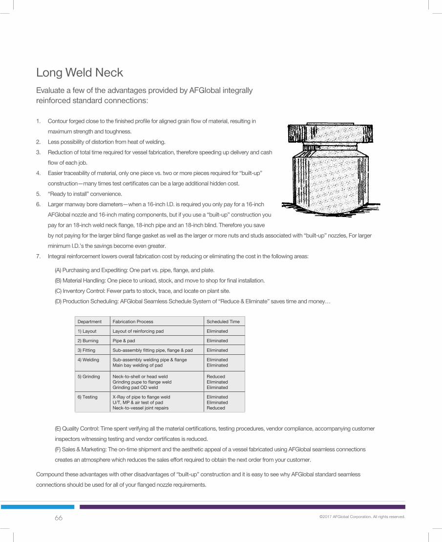
66 ©2017 AFGlobal Corporation. All rights reserved.
Evaluate a few of the advantages provided by AFGlobal integrally reinforced standard connections:
1. Contourforgedclosetothefinishedprofileforalignedgrainflowofmaterial,resultingin
maximumstrengthandtoughness.
2. Lesspossibilityofdistortionfromheatofwelding.
3. Reductionoftotaltimerequiredforvesselfabrication,thereforespeedingupdeliveryandcash
flowofeachjob.
4. Easiertraceabilityofmaterial,onlyonepiecevs.twoormorepiecesrequiredfor“built-up”
construction—manytimestestcertificatescanbealargeadditionalhiddencost.
5. “Readytoinstall”convenience.
6. Largermanwayborediameters—whena16-inchI.D.isrequiredyouonlypayfora16-inch
AFGlobalnozzleand16-inchmatingcomponents,butifyouusea“built-up”constructionyou
payforan18-inchweldneckflange,18-inchpipeandan18-inchblind.Thereforeyousave
bynotpayingforthelargerblindflangegasketaswellasthelargerormorenutsandstudsassociatedwith“built-up”nozzles,Forlarger
minimumI.D.’sthesavingsbecomeevengreater.
7. Integralreinforcementlowersoverallfabricationcostbyreducingoreliminatingthecostinthefollowingareas:
Compoundtheseadvantageswithotherdisadvantagesof“built-up”constructionanditiseasytoseewhyAFGlobalstandardseamless
connectionsshouldbeusedforallofyourflangednozzlerequirements.
(A)PurchasingandExpediting:Onepartvs.pipe,flange,andplate.
(B)MaterialHandling:Onepiecetounload,stock,andmovetoshopforfinalinstallation.
(C)InventoryControl:Fewerpartstostock,trace,andlocateonplantsite.
(D)ProductionScheduling:AFGlobalSeamlessScheduleSystemof“Reduce&Eliminate”savestimeandmoney…
(E)QualityControl:Timespentverifyingallthematerialcertifications,testingprocedures,vendorcompliance,accompanyingcustomer
inspectorswitnessingtestingandvendorcertificatesisreduced.
(F)Sales&Marketing:Theon-timeshipmentandtheaestheticappealofavesselfabricatedusingAFGlobalseamlessconnections
createsanatmospherewhichreducesthesaleseffortrequiredtoobtainthenextorderfromyourcustomer.
Department FabricationProcess ScheduledTime
1)Layout Layoutofreinforcingpad Eliminated
2)Burning Pipe&pad Eliminated
3)Fitting Sub-assemblyfittingpipe,flange&pad Eliminated
4)Welding Sub-assemblyweldingpipe&flangeMainbayweldingofpad
EliminatedEliminated
5)Grinding Neck-to-shellorheadweldGrindingpupetoflangeweldGrindingpadODweld
ReducedEliminatedEliminated
6)Testing X-RayofpipetoflangeweldU/T,MP&airtestofpadNeck-to-vesseljointrepairs
EliminatedEliminatedReduced
Long Weld Neck
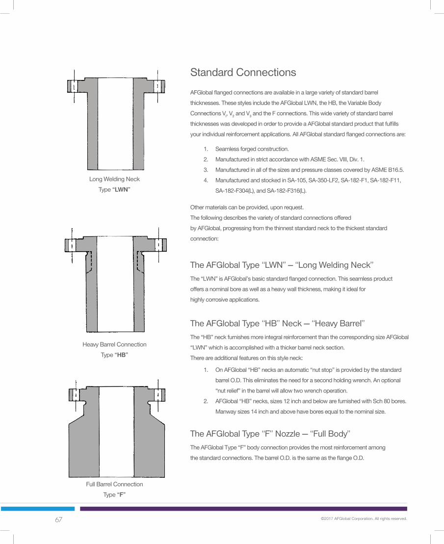
67 ©2017 AFGlobal Corporation. All rights reserved.
Standard Connections
The AFGlobal Type “LWN” -- “Long Welding Neck”
The AFGlobal Type “HB” Neck — “Heavy Barrel”
The AFGlobal Type “F” Nozzle — “Full Body”
AFGlobalflangedconnectionsareavailableinalargevarietyofstandardbarrel
thicknesses.ThesestylesincludetheAFGlobalLWN,theHB,theVariableBody
ConnectionsVl,V2andV3andtheFconnections.Thiswidevarietyofstandardbarrel
thicknesseswasdevelopedinordertoprovideaAFGlobalstandardproductthatfulfills
yourindividualreinforcementapplications.AllAFGlobalstandardflangedconnectionsare:
Othermaterialscanbeprovided,uponrequest.
Thefollowingdescribesthevarietyofstandardconnectionsoffered
byAFGlobal,progressingfromthethinneststandardnecktothethickeststandard
connection:
The“LWN”isAFGlobal’sbasicstandardflangedconnection.Thisseamlessproduct
offersanominalboreaswellasaheavywallthickness,makingitidealfor
highlycorrosiveapplications.
The“HB”neckfurnishesmoreintegralreinforcementthanthecorrespondingsizeAFGlobal
“LWN”whichisaccomplishedwithathickerbarrelnecksection.
Thereareadditionalfeaturesonthisstyleneck:
TheAFGlobalType“F”bodyconnectionprovidesthemostreinforcementamong
thestandardconnections.ThebarrelO.D.isthesameastheflangeO.D.
1. Seamlessforgedconstruction.
2. ManufacturedinstrictaccordancewithASMESec.VIII,Div.1.
3. ManufacturedinallofthesizesandpressureclassescoveredbyASMEB16.5.
4. ManufacturedandstockedinSA-105,SA-350-LF2,SA-182-F1,SA-182-F11,
SA-182-F304(L),andSA-182-F316(L).
1. OnAFGlobal“HB”necksanautomatic“nutstop”isprovidedbythestandard
barrelO.D.Thiseliminatestheneedforasecondholdingwrench.Anoptional
“nutrelief”inthebarrelwillallowtwowrenchoperation.
2. AFGlobal“HB”necks,sizes12inchandbelowarefurnishedwithSch80bores.
Manwaysizes14inchandabovehaveboresequaltothenominalsize.
Long Welding Neck
Type “LWN”
Heavy Barrel Connection
Type “HB”
Full Barrel Connection
Type “F”

68 ©2017 AFGlobal Corporation. All rights reserved.
Variable Body Connections
The AFGlobal Type “V” Nozzle -- “Variable Body”
Don’t Compromise
Optional Features
Neverbeforehasamanufacturerofferedsomanystandardbarrelthicknesses
inseamlessconnections.ThisvarietyenablesAFGlobaltoprovideasufficient
amountofintegralreinforcementrequiredwhilekeepingnozzleweightand
costdowntoaminimum.Don’tcompromisewithanexpensive“custom”
forgingwhenyoucanfindtherequiredbarreldiameterinthestandardAFGlobal
“VariableBody”chartsonthefollowingpages.TheAFGlobal“VariableBody”
connectionsprovidemoreintegralreinforcementthanan“HB”neck,without
theaddedcostofacustomforgingortheaddedcostandweightofan“F”
connection.
IfyourreinforcementrequirementscannotbemetwiththesestandardAFGlobal
products,pleasecalloursalesdepartmentat713-393-4200orvisitusonthewebat
www.afglobalcorp.com
AllAFGlobalconnectionsareavailablewiththefollowingoptionalfeatures:
1. contouredbottoms:“cylindrical”,“spherical,”or“hillside”.
2. speciallengths,longerorshorterthanthestandardlengthslistedinthepricelistareno
problemforAFGlobal.
3. insertlips,contourforgedorcontourmachined.
4. additionalfacings,standardB16.5orcustomdesigns.
5. “nutstop”barrel,(exceptonLWN’S).
6. optionalBarrelO.D.andI.D.
7. AFGlobalcanalsomakeLWNs,HBs,VariableBodyNozzles,andFNozzlestoASME
B16.47SeriesAandSeriesB.
Type “V1”
Type “V2”
Type “V3”

69 ©2017 AFGlobal Corporation. All rights reserved.
Class 150
FVC Standard Connections
12
CLASS
150 FVC Standard Connections
Material: FVC forged connections are made from SA-105 in compliance with ASME Section II. FVC connections are available in othermaterial compositions upon request. See “Technical Section” on page 59 for stocked materials.
Length: The length of all connections includes the barrel, flange and facing. See the current FVC price sheet for standard lengths.Intermediate lengths and longer are available upon request.
Facing: The FVC flange thickness “T” includes 0.06 inch raised face per ASME B16.5. This differs on Class 400 and above. FVC cansupply any special facing as needed upon request.
Notes continued on following page.
Bore Barrel O.D.Flange Flange RF Bolt Hole Bolt
Size O.D. Thick. O.D. Holes Size Circle LWN/F HB LWN HB F
O T R - - C B B D D D
½ 3.50 0.44 1.38 4 0.62 2.38 0.50 0.55 1.25 1.50 3.50¾ 3.88 0.50 1.69 4 0.62 2.75 0.75 0.74 1.62 1.88 3.881 4.25 0.56 2.00 4 0.62 3.12 1.00 0.96 2.00 2.25 4.25
1¼ 4.62 0.62 2.50 4 0.62 3.50 1.25 1.28 2.38 2.62 4.631½ 5.00 0.69 2.88 4 0.62 3.88 1.50 1.50 2.62 3.00 5.002 6.00 0.75 3.62 4 0.75 4.75 2.00 1.94 3.06 3.69 6.00
2½ 7.00 0.88 4.12 4 0.75 5.50 2.50 2.32 3.75 4.44 7.003 7.50 0.94 5.00 4 0.75 6.00 3.00 2.90 4.25 4.94 7.50
3½ 8.50 0.94 5.50 8 0.75 7.00 3.50 3.36 4.88 5.94 8.504 9.00 0.94 6.19 8 0.75 7.50 4.00 3.83 5.50 6.44 9.005 10.00 0.94 7.31 8 0.88 8.50 5.00 4.81 6.50 7.25 10.006 11.00 1.00 8.50 8 0.88 9.50 6.00 5.76 7.75 8.25 11.008 13.50 1.12 10.62 8 0.88 11.75 8.00 7.62 9.75 10.50 13.50
10 16.00 1.19 12.75 12 1.00 14.25 10.00 9.56 12.00 12.81 16.0012 19.00 1.25 15.00 12 1.00 17.00 12.00 11.38 14.38 15.56 19.0014 21.00 1.38 16.25 12 1.12 18.75 14.00 14.00 16.00 17.12 21.0016 23.50 1.44 18.50 16 1.12 21.25 16.00 16.00 18.00 19.62 23.5018 25.00 1.56 21.00 16 1.25 22.75 18.00 18.00 20.00 20.94 25.0020 27.50 1.69 23.00 20 1.25 25.00 20.00 20.00 22.00 23.19 27.5024 32.00 1.88 27.25 20 1.38 29.50 24.00 24.00 26.25 27.50 32.00

70 ©2017 AFGlobal Corporation. All rights reserved.
Class 150
FVC Standard Connections
13
Nut Nut NutStop Relief ReliefDia. Dia. Lngth.
BaseWt.
Lngth.Base Wt.Wt. 1”
Base Wt.Wt. 1”
Base Wt.Wt. 1”
LWN HB F
Bolting and Tolerances: FVC flanges are furnished to ASME B16.5 specifications unless otherwise specified.
Nut Relief: All FVC connections except standard LWN’s will be supplied with a “nut stop O.D.” unless a “nut relief O.D.” is specified.
Bore: Bore sizes shown above are standard, other sizes can be furnished upon request.
Curving: All FVC connections can be furnished contoured to fit any shell, head or cone at a minimal cost.
See page 40 for complete general notes.
FVC Standard Connections
CLASS
150DON’T COMPROMISE!
If your reinforcementrequirements are inbetween the “HB”and “F” connectionssee the followingpage for Class 150FVC Variable BodyConnections
Neck Thickness Weights
Size LWN HB F
NS NR NL N N N
½ 1.50 1.25 0.75 0.38 0.48 1.50 3 0.3 5 0.4 21 2.7 9¾ 1.88 1.62 0.75 0.44 0.57 1.56 5 0.5 7 0.7 27 3.2 91 2.25 2.00 0.75 0.50 0.65 1.62 7 0.7 10 0.9 30 3.8 9
1¼ 2.62 2.38 0.75 0.56 0.67 1.69 10 0.9 12 1.2 36 4.4 91½ 3.00 2.62 0.75 0.56 0.75 1.75 12 1.0 16 1.5 41 5.1 92 3.69 3.06 0.88 0.53 0.88 2.00 15 1.2 23 2.2 57 7.1 9
2½ 4.44 3.75 0.88 0.62 1.06 2.25 22 1.7 34 3.2 79 10 93 4.94 4.25 0.88 0.62 1.02 2.25 25 2.0 38 3.6 86 11 9
3½ 5.94 4.88 0.88 0.69 1.29 2.50 32 2.6 55 5.3 110 13 94 6.44 5.50 0.88 0.75 1.31 2.50 47 3.2 78 6.0 164 14 125 7.25 6.50 1.00 0.75 1.22 2.50 57 3.8 87 6.5 189 17 126 8.25 7.75 1.00 0.88 1.25 2.50 75 5.4 103 7.8 216 19 128 10.50 9.75 1.00 0.88 1.44 2.75 102 6.9 157 11 292 26 1210 12.81 12.00 1.12 1.00 1.63 3.00 143 9.8 214 16 382 35 1212 15.56 14.38 1.12 1.19 2.09 3.50 205 14 329 25 535 48 1214 17.12 16.00 1.25 1.00 1.56 3.50 211 13 296 22 585 55 1216 19.62 18.00 1.25 1.00 1.81 3.75 246 15 388 29 714 66 1218 20.94 20.00 1.38 1.00 1.47 3.50 270 17 362 25 711 67 1220 23.19 22.00 1.38 1.00 1.60 3.75 311 19 434 31 840 79 1224 27.50 26.25 1.50 1.12 1.75 4.00 423 25 574 40 1046 100 12
See page 97 for complete general notes.

71 ©2017 AFGlobal Corporation. All rights reserved.
Class 150
FVC Variable Body Connections
14
CLASS
150 FVC Variable Body Connections
Material: FVC forged connections are made from SA-105 in compliance with ASME Section II. FVC connections are available in othermaterial compositions upon request. See “Technical Section” on page 59 for stocked materials.
Length: The length of all connections includes the barrel, flange and facing. See the current FVC price sheet for standard lengths.Intermediate lengths and longer are available upon request.
Facing: The FVC flange thickness “T” includes 0.06 inch raised face per ASME B16.5. This differs on Class 400 and above. FVC cansupply any special facing as needed upon request.
Notes continued on following page.
Barrel O.D.Flange Flange RF Bolt Hole Bolt
Size O.D. Thick. O.D. Holes Size Circle Bore V1 V2 V3
O T R - - C B DV1 DV2 DV3
1 4.25 0.56 2.00 4 0.62 3.12 0.96 2.75 3.25 4.001½ 5.00 0.69 2.88 4 0.62 3.88 1.50 3.25 4.00 4.622 6.00 0.75 3.62 4 0.75 4.75 1.94 4.00 4.62 5.50
2½ 7.00 0.88 4.12 4 0.75 5.50 2.32 4.62 5.75 6.003 7.50 0.94 5.00 4 0.75 6.00 2.90 5.75 6.00 6.38
3½ 8.50 0.94 5.50 8 0.75 7.00 3.36 6.38 7.00 7.754 9.00 0.94 6.19 8 0.75 7.50 3.83 7.00 7.75 8.255 10.00 0.94 7.31 8 0.88 8.50 4.81 7.75 8.25 8.886 11.00 1.00 8.50 8 0.88 9.50 5.76 8.88 9.88 10.388 13.50 1.12 10.62 8 0.88 11.75 7.62 11.00 11.50 12.12
10 16.00 1.19 12.75 12 1.00 14.25 9.56 13.50 14.25 15.1212 19.00 1.25 15.00 12 1.00 17.00 11.38 16.25 17.38 18.2514 21.00 1.38 16.25 12 1.12 18.75 14.00 18.25 19.38 20.1216 23.50 1.44 18.50 16 1.12 21.25 16.00 20.12 21.00 22.2518 25.00 1.56 21.00 16 1.25 22.75 18.00 22.25 23.25 24.1220 27.50 1.69 23.00 20 1.25 25.00 20.00 24.12 25.00 26.2524 32.00 1.88 27.25 20 1.38 29.50 24.00 27.75 29.25 30.75

72 ©2017 AFGlobal Corporation. All rights reserved.
15
Neck Thickness Weights
Size V1 V2 V3
NS NR NL N N N
1 2.25 2.00 0.75 0.90 1.15 1.52 19 1.5 26 2.2 38 3.4 121½ 3.00 2.62 0.75 0.88 1.25 1.56 25 1.9 37 3.1 49 4.3 122 3.69 3.06 0.88 1.03 1.34 1.78 35 2.7 48 3.9 67 5.9 12
2½ 4.44 3.75 0.88 1.15 1.72 1.84 48 3.5 73 6 81 7 123 4.94 4.25 0.88 1.43 1.55 1.74 69 5.5 75 6 85 7 12
3½ 5.94 4.88 0.88 1.51 1.82 2.20 83 7 102 8 126 11 124 6.44 5.50 0.88 1.59 1.96 2.21 95 8 119 10 137 12 125 7.25 6.50 1.00 1.47 1.72 2.04 104 8 121 10 144 12 126 8.25 7.75 1.00 1.56 2.06 2.31 126 10 167 14 188 17 128 10.50 9.75 1.00 1.69 1.94 2.25 180 14 205 17 236 20 1210 12.81 12.00 1.12 1.97 2.35 2.78 337 20 399 25 474 31 1612 15.56 14.38 1.12 2.44 3.00 3.44 494 30 606 38 696 45 1614 17.12 16.00 1.25 2.13 2.69 3.06 501 31 622 40 705 47 1616 19.62 18.00 1.25 2.06 2.50 3.13 562 33 666 41 820 53 1618 20.94 20.00 1.38 2.13 2.63 3.06 624 38 751 48 864 57 1620 23.19 22.00 1.38 2.06 2.50 3.13 684 41 804 50 978 64 1624 27.50 26.25 1.50 1.88 2.63 3.38 772 43 1007 62 1246 82 16
Nut Nut NutStop Relief ReliefDia. Dia. Lngth.
BaseWt.
Lngth.Base Wt.Wt. 1”
Base Wt.Wt. 1”
Base Wt.Wt. 1”
V1 V2 V3
FVC Variable Body Connections
CLASS
150
Bolting and Tolerances: FVC flanges are furnished to ASME B16.5 specifications unless otherwise specified.
Nut Relief: All FVC connections except standard LWN’s will be supplied with a “nut stop O.D.” unless a “nut relief O.D.” is specified.
Bore: Bore sizes shown above are standard, other sizes can be furnished upon request.
Curving: All FVC connections can be furnished contoured to fit any shell, head or cone at a minimal cost.
See page 40 for complete general notes.
DON’T COMPROMISE!
If your reinforcementrequirements havenot been met withthese standard FVCconnections, pleasesee “CustomProducts”, pages54 to 56.
Class 150
Variable Body Connections
See page 97 for complete general notes.

73 ©2017 AFGlobal Corporation. All rights reserved.
Class 300
FVC Standard Connections
16
Bore Barrel O.D.Flange Flange RF Bolt Hole Bolt
Size O.D. Thick. O.D. Holes Size Circle LWN/F HB LWN HB F
O T R - - C B B D D D
½ 3.75 0.56 1.38 4 0.62 2.62 0.50 0.55 1.50 1.75 3.75¾ 4.62 0.62 1.69 4 0.75 3.25 0.75 0.74 1.88 2.19 4.621 4.88 0.69 2.00 4 0.75 3.50 1.00 0.96 2.12 2.44 4.88
1¼ 5.25 0.75 2.50 4 0.75 3.88 1.25 1.28 2.50 2.81 5.251½ 6.12 0.81 2.88 4 0.88 4.50 1.50 1.50 2.75 3.25 6.122 6.50 0.88 3.62 8 0.75 5.00 2.00 1.94 3.31 3.94 6.50
2½ 7.50 1.00 4.12 8 0.88 5.88 2.50 2.32 3.94 4.62 7.503 8.25 1.12 5.00 8 0.88 6.62 3.00 2.90 4.62 5.38 8.25
3½ 9.00 1.19 5.50 8 0.88 7.25 3.50 3.36 5.25 6.00 9.004 10.00 1.25 6.19 8 0.88 7.88 4.00 3.83 5.75 6.62 10.005 11.00 1.38 7.31 8 0.88 9.25 5.00 4.81 7.00 8.00 11.006 12.50 1.44 8.50 12 0.88 10.62 6.00 5.76 8.12 9.38 12.508 15.00 1.62 10.62 12 1.00 13.00 8.00 7.62 10.25 11.56 15.00
10 17.50 1.88 12.75 16 1.12 15.25 10.00 9.56 12.62 13.62 17.5012 20.50 2.00 15.00 16 1.25 17.75 12.00 11.38 14.75 15.94 20.5014 23.00 2.12 16.25 20 1.25 20.25 14.00 14.00 16.75 18.44 23.0016 25.50 2.25 18.50 20 1.38 22.50 16.00 16.00 19.00 20.50 25.5018 28.00 2.38 21.00 24 1.38 24.75 18.00 18.00 21.00 22.75 28.0020 30.50 2.50 23.00 24 1.38 27.00 20.00 20.00 23.12 25.00 30.5024 36.00 2.75 27.25 24 1.62 32.00 24.00 24.00 27.62 29.62 36.00
CLASS
300 FVC Standard Connections
Material: FVC forged connections are made from SA-105 in compliance with ASME Section II. FVC connections are available in othermaterial compositions upon request. See “Technical Section” on page 59 for stocked materials.
Length: The length of all connections includes the barrel, flange and facing. See the current FVC price sheet for standard lengths.Intermediate lengths and longer are available upon request.
Facing: The FVC flange thickness “T” includes 0.06 inch raised face per ASME B16.5. This differs on Class 400 and above. FVC cansupply any special facing as needed upon request.
Notes continued on following page.

74 ©2017 AFGlobal Corporation. All rights reserved.
Class 300
FVC Standard Connections
17
Neck Thickness Weights
Size LWN HB F
NS NR NL N N N
½ 1.75 1.50 0.75 0.50 0.60 1.63 5 0.4 7 0.6 24 3.1 9¾ 2.19 1.88 0.88 0.57 0.73 1.94 9 0.7 11 0.9 37 4.6 91 2.44 2.12 0.88 0.56 0.74 1.94 9 0.8 12 1.1 40 5.1 9
1¼ 2.81 2.50 0.88 0.63 0.77 2.00 13 1.0 15 1.4 45 5.8 91½ 3.25 2.75 1.00 0.63 0.88 2.31 15 1.2 21 1.9 61 7.8 92 3.94 3.31 0.88 0.66 1.00 2.25 20 1.5 28 2.6 68 8.5 9
2½ 4.62 3.94 1.00 0.72 1.15 2.50 25 2.1 38 3.6 89 11 93 5.38 4.62 1.00 0.81 1.24 2.63 35 2.7 49 4.6 106 13 9
3½ 6.00 5.25 1.00 0.88 1.32 2.75 42 3.4 59 5.5 122 15 94 6.62 5.75 1.00 0.88 1.40 3.00 62 3.8 91 6.5 207 19 125 8.00 7.00 1.00 1.00 1.60 3.00 84 5.3 124 9.1 241 21 126 9.38 8.12 1.00 1.06 1.81 3.25 105 6.7 165 12 303 27 128 11.56 10.25 1.12 1.13 1.97 3.50 148 9.1 228 17 405 36 1210 13.62 12.62 1.25 1.31 2.03 3.75 210 13 291 21 499 46 1212 15.94 14.75 1.38 1.38 2.28 4.25 275 16 392 28 651 61 1214 18.44 16.75 1.38 1.38 2.22 4.50 324 19 456 32 785 74 1216 20.50 19.00 1.50 1.50 2.25 4.75 404 23 529 37 914 88 1218 22.75 21.00 1.50 1.50 2.38 5.00 465 26 630 43 1066 102 1220 25.00 23.12 1.50 1.56 2.50 5.25 549 30 741 50 1228 118 1224 29.62 27.62 1.75 1.81 2.81 6.00 778 42 1016 67 1627 160 12
Nut Nut NutStop Relief ReliefDia. Dia. Lngth.
BaseWt.
Lngth.Base Wt.Wt. 1”
Base Wt.Wt. 1”
Base Wt.Wt. 1”
LWN HB F
Bolting and Tolerances: FVC flanges are furnished to ASME B16.5 specifications unless otherwise specified.
Nut Relief: All FVC connections except standard LWN’s will be supplied with a “nut stop O.D.” unless a “nut relief O.D.” is specified.
Bore: Bore sizes shown above are standard, other sizes can be furnished upon request.
Curving: All FVC connections can be furnished contoured to fit any shell, head or cone at a minimal cost.
See page 40 for complete general notes.
FVC Standard Connections
CLASS
300DON’T COMPROMISE!
If your reinforcementrequirements are inbetween the “HB”and “F” connectionssee the followingpage for Class 300FVC Variable BodyConnections
See page 97 for complete general notes.

75 ©2017 AFGlobal Corporation. All rights reserved.
Class 300
FVC Variable Body Connections
18
Barrel O.D.Flange Flange RF Bolt Hole Bolt
Size O.D. Thick. O.D. Holes Size Circle Bore V1 V2 V3
O T R - - C B DV1 DV2 DV3
1 4.88 0.69 2.00 4 0.75 3.50 0.96 2.75 3.75 4.001½ 6.12 0.81 2.88 4 0.88 4.50 1.50 4.00 4.62 5.502 6.50 0.88 3.62 8 0.75 5.00 1.94 4.62 5.50 6.00
2½ 7.50 1.00 4.12 8 0.88 5.88 2.32 5.75 6.00 6.383 8.25 1.12 5.00 8 0.88 6.62 2.90 6.00 6.38 7.00
3½ 9.00 1.19 5.50 8 0.88 7.25 3.36 7.00 7.75 8.254 10.00 1.25 6.19 8 0.88 7.88 3.83 7.00 7.75 8.885 11.00 1.38 7.31 8 0.88 9.25 4.81 8.25 8.88 9.886 12.50 1.44 8.50 12 0.88 10.62 5.76 9.88 10.38 11.008 15.00 1.62 10.62 12 1.00 13.00 7.62 12.12 13.50 14.25
10 17.50 1.88 12.75 16 1.12 15.25 9.56 14.25 15.12 16.2512 20.50 2.00 15.00 16 1.25 17.75 11.38 16.25 17.38 18.2514 23.00 2.12 16.25 20 1.25 20.25 14.00 19.38 20.12 22.2516 25.50 2.25 18.50 20 1.38 22.50 16.00 22.25 23.25 24.1218 28.00 2.38 21.00 24 1.38 24.75 18.00 24.12 25.12 26.7520 30.50 2.50 23.00 24 1.38 27.00 20.00 26.75 27.75 29.2524 36.00 2.75 27.25 24 1.62 32.00 24.00 30.75 32.00 33.62
CLASS
300 FVC Variable Body Connections
Material: FVC forged connections are made from SA-105 in compliance with ASME Section II. FVC connections are available in othermaterial compositions upon request. See “Technical Section” on page 59 for stocked materials.
Length: The length of all connections includes the barrel, flange and facing. See the current FVC price sheet for standard lengths.Intermediate lengths and longer are available upon request.
Facing: The FVC flange thickness “T” includes 0.06 inch raised face per ASME B16.5. This differs on Class 400 and above. FVC cansupply any special facing as needed upon request.
Notes continued on following page.

76 ©2017 AFGlobal Corporation. All rights reserved.
Class 300
FVC Variable Body Connections
19
Neck Thickness Weights
Size V1 V2 V3
NS NR NL N N N
1 2.44 2.12 0.88 0.90 1.40 1.52 20 1.5 34 2.9 39 3.4 121½ 3.25 2.75 1.00 1.25 1.56 2.00 39 3.1 51 4.3 70 6.2 122 3.94 3.31 0.88 1.34 1.78 2.03 49 3.9 69 5.9 81 7.2 12
2½ 4.62 3.94 1.00 1.72 1.84 2.03 72 6.2 80 6.8 90 7.8 123 5.38 4.62 1.00 1.55 1.74 2.05 78 6.1 88 7.2 106 9 12
3½ 6.00 5.25 1.00 1.82 2.20 2.45 104 8.4 127 11 144 13 124 6.62 5.75 1.00 1.59 1.96 2.52 102 7.6 125 10 164 14 125 8.00 7.00 1.00 1.72 2.04 2.54 133 10 155 12 194 17 126 9.38 8.12 1.00 2.06 2.31 2.62 185 14 206 17 233 20 128 11.56 10.25 1.12 2.25 2.94 3.32 255 20 324 28 364 32 1210 13.62 12.62 1.25 2.35 2.78 3.35 425 25 498 31 591 38 1612 15.94 14.75 1.38 2.44 3.00 3.44 532 30 636 38 720 45 1614 18.44 16.75 1.38 2.69 3.06 4.13 681 40 761 47 996 67 1616 20.50 19.00 1.50 3.13 3.63 4.06 877 53 988 63 1099 73 1618 22.75 21.00 1.50 3.06 3.56 4.38 982 57 1102 68 1314 87 1620 25.00 23.12 1.50 3.38 3.88 4.63 1176 70 1316 82 1525 101 1624 29.62 27.62 1.75 3.38 4.00 4.81 1455 82 1647 100 1899 123 16
Nut Nut NutStop Relief ReliefDia. Dia. Lngth.
BaseWt.
Lngth.Base Wt.Wt. 1”
Base Wt.Wt. 1”
Base Wt.Wt. 1”
V1 V2 V3
FVC Variable Body Connections
CLASS
300
Bolting and Tolerances: FVC flanges are furnished to ASME B16.5 specifications unless otherwise specified.
Nut Relief: All FVC connections except standard LWN’s will be supplied with a “nut stop O.D.” unless a “nut relief O.D.” is specified.
Bore: Bore sizes shown above are standard, other sizes can be furnished upon request.
Curving: All FVC connections can be furnished contoured to fit any shell, head or cone at a minimal cost.
See page 40 for complete general notes.
DON’T COMPROMISE!
If your reinforcementrequirements havenot been met withthese standard FVCconnections, pleasesee “CustomProducts”, pages54 to 56.
See page 97 for complete general notes.
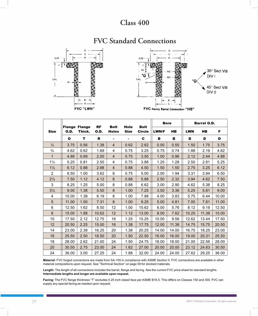
77 ©2017 AFGlobal Corporation. All rights reserved.
Class 400
FVC Standard Connections
20
Bore Barrel O.D.Flange Flange RF Bolt Hole Bolt
Size O.D. Thick. O.D. Holes Size Circle LWN/F HB LWN HB F
O T R - - C B B D D D
½ 3.75 0.56 1.38 4 0.62 2.62 0.50 0.55 1.50 1.75 3.75¾ 4.62 0.62 1.69 4 0.75 3.25 0.75 0.74 1.88 2.19 4.621 4.88 0.69 2.00 4 0.75 3.50 1.00 0.96 2.12 2.44 4.88
1¼ 5.25 0.81 2.50 4 0.75 3.88 1.25 1.28 2.50 2.81 5.251½ 6.12 0.88 2.88 4 0.88 4.50 1.50 1.50 2.75 3.25 6.122 6.50 1.00 3.62 8 0.75 5.00 2.00 1.94 3.31 3.94 6.50
2½ 7.50 1.12 4.12 8 0.88 5.88 2.50 2.32 3.94 4.62 7.503 8.25 1.25 5.00 8 0.88 6.62 3.00 2.90 4.62 5.38 8.25
3½ 9.00 1.38 5.50 8 1.00 7.25 3.50 3.36 5.25 5.81 9.004 10.00 1.38 6.19 8 1.00 7.88 4.00 3.83 5.75 6.44 10.005 11.00 1.50 7.31 8 1.00 9.25 5.00 4.81 7.00 7.81 11.006 12.50 1.62 8.50 12 1.00 10.62 6.00 5.76 8.12 9.19 12.508 15.00 1.88 10.62 12 1.12 13.00 8.00 7.62 10.25 11.38 15.00
10 17.50 2.12 12.75 16 1.25 15.25 10.00 9.56 12.62 13.44 17.5012 20.50 2.25 15.00 16 1.38 17.75 12.00 11.38 14.75 15.75 20.5014 23.00 2.38 16.25 20 1.38 20.25 14.00 14.00 16.75 18.25 23.0016 25.50 2.50 18.50 20 1.50 22.50 16.00 16.00 19.00 20.31 25.5018 28.00 2.62 21.00 24 1.50 24.75 18.00 18.00 21.00 22.56 28.0020 30.50 2.75 23.00 24 1.62 27.00 20.00 20.00 23.12 24.63 30.5024 36.00 3.00 27.25 24 1.88 32.00 24.00 24.00 27.62 29.25 36.00
CLASS
400 FVC Standard Connections
Material: FVC forged connections are made from SA-105 in compliance with ASME Section II. FVC connections are available in othermaterial compositions upon request. See “Technical Section” on page 59 for stocked materials.
Length: The length of all connections includes the barrel, flange and facing. See the current FVC price sheet for standard lengths.Intermediate lengths and longer are available upon request.
Facing: The FVC flange thickness “T” excludes 0.25 inch raised face per ASME B16.5. This differs on Classes 150 and 300. FVC cansupply any special facing as needed upon request.
Notes continued on following page.

78 ©2017 AFGlobal Corporation. All rights reserved.
Class 400
FVC Standard Connections
21
Neck Thickness Weights
Size LWN HB F
NS NR NL N N N
½ 1.75 1.50 0.75 0.50 0.60 1.63 5 0.4 7 0.6 24 3.1 9¾ 2.19 1.88 0.88 0.57 0.73 1.94 8 0.7 11 0.9 37 4.6 91 2.44 2.12 0.88 0.56 0.74 1.94 9 0.8 12 1.1 40 5.1 9
1¼ 2.81 2.50 0.88 0.63 0.77 2.00 13 1.0 15 1.4 45 5.8 91½ 3.25 2.75 1.00 0.63 0.88 2.31 16 1.2 21 1.9 61 7.8 92 3.94 3.31 0.88 0.66 1.00 2.25 20 1.5 29 2.6 68 8.5 9
2½ 4.62 3.94 1.00 0.72 1.15 2.50 27 2.1 39 3.6 88 11 93 5.38 4.62 1.00 0.81 1.24 2.63 36 2.7 50 4.6 104 13 9
3½ 5.81 5.25 1.12 0.88 1.23 2.75 45 3.4 61 5.5 116 15 94 6.44 5.75 1.12 0.88 1.31 3.00 65 3.8 93 6.5 197 19 125 7.81 7.00 1.12 1.00 1.50 3.00 88 5.3 127 9.1 229 22 126 9.19 8.12 1.12 1.06 1.72 3.25 110 6.7 169 12 286 27 128 11.38 10.25 1.25 1.13 1.88 3.50 154 9.1 233 17 379 36 1210 13.44 12.62 1.38 1.31 1.94 3.75 218 13 298 21 475 46 1212 15.75 14.75 1.50 1.38 2.19 4.25 285 16 401 28 627 62 1214 18.25 16.75 1.50 1.38 2.13 4.50 336 19 467 32 758 74 1216 20.31 19.00 1.62 1.50 2.16 4.75 418 23 542 37 884 88 1218 22.56 21.00 1.62 1.50 2.28 5.00 482 26 645 43 1033 102 1220 24.63 23.12 1.75 1.56 2.32 5.25 568 30 759 50 1165 118 1224 29.25 27.62 2.00 1.81 2.63 6.00 804 42 1040 67 1540 160 12
Nut Nut NutStop Relief ReliefDia. Dia. Lngth.
BaseWt.
Lngth.Base Wt.Wt. 1”
Base Wt.Wt. 1”
Base Wt.Wt. 1”
LWN HB F
Bolting and Tolerances: FVC flanges are furnished to ASME B16.5 specifications unless otherwise specified.
Nut Relief: All FVC connections except standard LWN’s will be supplied with a “nut stop O.D.” unless a “nut relief O.D.” is specified.
Bore: Bore sizes shown above are standard, other sizes can be furnished upon request.
Curving: All FVC connections can be furnished contoured to fit any shell, head or cone at a minimal cost.
See page 40 for complete general notes.
FVC Standard Connections
CLASS
400DON’T COMPROMISE!
If your reinforcementrequirements are inbetween the “HB”and “F” connectionssee the followingpage for Class 400FVC Variable BodyConnections
See page 97 for complete general notes.

79 ©2017 AFGlobal Corporation. All rights reserved.
Class 400
FVC Variable Body Connections
22
Barrel O.D.Flange Flange RF Bolt Hole Bolt
Size O.D. Thick. O.D. Holes Size Circle Bore V1 V2 V3
O T R - - C B DV1 DV2 DV3
1 4.88 0.69 2.00 4 0.75 3.50 0.96 2.75 3.25 4.001½ 6.12 0.88 2.88 4 0.88 4.50 1.50 4.00 4.62 5.502 6.50 1.00 3.62 8 0.75 5.00 1.94 4.62 5.50 6.00
2½ 7.50 1.13 4.12 8 0.88 5.88 2.32 5.75 6.00 6.383 8.25 1.25 5.00 8 0.88 6.62 2.90 6.00 6.38 7.00
3½ 9.00 1.38 5.50 8 1.00 7.25 3.36 7.00 7.75 8.254 10.00 1.38 6.19 8 1.00 7.88 3.83 7.00 7.75 8.885 11.00 1.50 7.31 8 1.00 9.25 4.81 8.25 8.88 9.886 12.50 1.62 8.50 12 1.00 10.62 5.76 9.88 10.38 11.008 15.00 1.88 10.62 12 1.12 13.00 7.62 12.12 13.50 14.25
10 17.50 2.12 12.75 16 1.25 15.25 9.56 14.25 15.12 16.2512 20.50 2.25 15.00 16 1.38 17.75 11.38 16.25 17.38 18.2514 23.00 2.38 16.25 20 1.38 20.25 14.00 19.38 20.12 22.2516 25.50 2.50 18.50 20 1.50 22.50 16.00 22.25 23.25 24.1218 28.00 2.62 21.00 24 1.50 24.75 18.00 24.12 25.12 26.7520 30.50 2.75 23.00 24 1.62 27.00 20.00 26.75 27.75 29.2524 36.00 3.00 27.25 24 1.88 32.00 24.00 30.75 32.00 33.62
CLASS
400 FVC Variable Body Connections
Material: FVC forged connections are made from SA-105 in compliance with ASME Section II. FVC connections are available in othermaterial compositions upon request. See “Technical Section” on page 59 for stocked materials.
Length: The length of all connections includes the barrel, flange and facing. See the current FVC price sheet for standard lengths.Intermediate lengths and longer are available upon request.
Facing: The FVC flange thickness “T” excludes 0.25 inch raised face per ASME B16.5. This differs on Classes 150 and 300. FVC cansupply any special facing as needed upon request.
Notes continued on following page.

80 ©2017 AFGlobal Corporation. All rights reserved.
Class 400
FVC Variable Body Connections
23
Neck Thickness Weights
Size V1 V2 V3
NS NR NL N N N
1 2.44 2.12 0.88 0.90 1.15 1.52 20 1.5 27 2.2 39 3.4 121½ 3.25 2.75 1.00 1.25 1.56 2.00 39 3.1 51 4.3 69 6.2 122 3.94 3.31 0.88 1.34 1.78 2.03 49 3.9 69 5.9 95 8.9 12
2½ 4.62 3.94 1.00 1.72 1.84 2.03 73 6.2 81 6.8 90 7.8 123 5.38 4.62 1.00 1.55 1.74 2.05 79 6.1 89 7.2 106 9 12
3½ 5.81 5.25 1.12 1.82 2.20 2.45 106 8.4 128 11 145 13 124 6.44 5.75 1.12 1.59 1.96 2.53 104 7.6 126 10 165 14 125 7.81 7.00 1.12 1.72 2.04 2.54 135 10 157 12 195 17 126 9.19 8.12 1.12 2.06 2.31 2.62 188 14 208 17 235 20 128 11.38 10.25 1.25 2.25 2.94 3.31 259 20 327 28 366 32 1210 13.44 12.62 1.38 2.35 2.78 3.35 431 25 502 31 594 38 1612 15.75 14.75 1.50 2.44 3.00 3.44 539 30 641 38 724 45 1614 18.25 16.75 1.50 2.69 3.06 4.13 690 40 768 47 974 67 1616 20.31 19.00 1.62 3.12 3.63 4.06 887 53 980 63 1078 73 1618 22.56 21.00 1.62 3.06 3.56 4.38 982 57 1102 68 1284 87 1620 24.63 23.12 1.75 3.38 3.88 4.63 1176 70 1283 82 1476 101 1624 29.25 27.62 2.00 3.38 4.00 4.81 1437 82 1614 100 1844 123 16
Nut Nut NutStop Relief ReliefDia. Dia. Lngth.
BaseWt.
Lngth.Base Wt.Wt. 1”
Base Wt.Wt. 1”
Base Wt.Wt. 1”
V1 V2 V3
FVC Variable Body Connections
CLASS
400
Bolting and Tolerances: FVC flanges are furnished to ASME B16.5 specifications unless otherwise specified.
Nut Relief: All FVC connections except standard LWN’s will be supplied with a “nut stop O.D.” unless a “nut relief O.D.” is specified.
Bore: Bore sizes shown above are standard, other sizes can be furnished upon request.
Curving: All FVC connections can be furnished contoured to fit any shell, head or cone at a minimal cost.
See page 40 for complete general notes.
DON’T COMPROMISE!
If your reinforcementrequirements havenot been met withthese standard FVCconnections, pleasesee “CustomProducts”, pages54 to 56.
DON’T COMPROMISE!
If your reinforcementrequirements havenot been met withthese standard FVCconnections, pleasesee “CustomProducts”, pages54 to 56.
See page 97 for complete general notes.

81 ©2017 AFGlobal Corporation. All rights reserved.
Class 600
FVC Standard Connections
24
Bore Barrel O.D.Flange Flange RF Bolt Hole Bolt
Size O.D. Thick. O.D. Holes Size Circle LWN/F HB LWN HB F
O T R - - C B B D D D
½ 3.75 0.56 1.38 4 0.62 2.62 0.50 0.55 1.50 1.75 3.75¾ 4.62 0.62 1.69 4 0.75 3.25 0.75 0.74 1.88 2.19 4.621 4.88 0.69 2.00 4 0.75 3.50 1.00 0.96 2.12 2.44 4.88
1¼ 5.25 0.81 2.50 4 0.75 3.88 1.25 1.28 2.50 2.81 5.251½ 6.12 0.88 2.88 4 0.88 4.50 1.50 1.50 2.75 3.25 6.122 6.50 1.00 3.62 8 0.75 5.00 2.00 1.94 3.31 3.94 6.50
2½ 7.50 1.12 4.12 8 0.88 5.88 2.50 2.32 3.94 4.62 7.503 8.25 1.25 5.00 8 0.88 6.62 3.00 2.90 4.62 5.38 8.25
3½ 9.00 1.38 5.50 8 1.00 7.25 3.50 3.36 5.25 5.81 9.004 10.75 1.50 6.19 8 1.00 8.50 4.00 3.83 6.00 7.06 10.755 13.00 1.75 7.31 8 1.12 10.50 5.00 4.81 7.50 8.88 13.006 14.00 1.88 8.50 12 1.12 11.50 6.00 5.76 8.75 9.88 14.008 16.50 2.19 10.62 12 1.25 13.75 8.00 7.62 10.75 11.94 16.50
10 20.00 2.50 12.75 16 1.38 17.00 10.00 9.56 13.50 15.00 20.0012 22.00 2.62 15.00 20 1.38 19.25 12.00 11.38 15.75 17.25 22.0014 23.75 2.75 16.25 20 1.50 20.75 14.00 14.00 17.00 18.56 23.7516 27.00 3.00 18.50 20 1.62 23.75 16.00 16.00 19.50 21.38 27.0018 29.25 3.25 21.00 20 1.75 25.75 18.00 18.00 21.50 23.19 29.2520 32.00 3.50 23.00 24 1.75 28.50 20.00 20.00 24.00 25.94 32.0024 37.00 4.00 27.25 24 2.00 33.00 24.00 24.00 28.25 30.06 37.00
CLASS
600 FVC Standard Connections
Material: FVC forged connections are made from SA-105 in compliance with ASME Section II. FVC connections are available in othermaterial compositions upon request. See “Technical Section” on page 59 for stocked materials.
Length: The length of all connections includes the barrel, flange and facing. See the current FVC price sheet for standard lengths.Intermediate lengths and longer are available upon request.
Facing: The FVC flange thickness “T” excludes 0.25 inch raised face per ASME B16.5. This differs on Classes 150 and 300. FVC cansupply any special facing as needed upon request.
Notes continued on following page.

82 ©2017 AFGlobal Corporation. All rights reserved.
Class 600
FVC Standard Connections
25
Neck Thickness Weights
Size LWN HB F
NS NR NL N N N
½ 1.75 1.50 0.75 0.50 0.60 1.63 5 0.4 7 0.6 24 3.1 9¾ 2.19 1.88 0.88 0.57 0.73 1.94 8 0.7 11 0.9 36 4.6 91 2.44 2.12 0.88 0.56 0.74 1.94 9 0.8 12 1.1 39 5.1 9
1¼ 2.81 2.50 0.88 0.63 0.77 2.00 13 1.0 15 1.4 44 5.8 91½ 3.25 2.75 1.00 0.63 0.88 2.31 16 1.2 21 1.9 59 7.8 92 3.94 3.31 0.88 0.66 1.00 2.25 20 1.5 29 2.6 67 8.5 9
2½ 4.62 3.94 1.00 0.72 1.15 2.50 27 2.1 39 3.6 85 11 93 5.38 4.62 1.00 0.81 1.24 2.63 36 2.7 50 4.6 104 13 9
3½ 5.81 5.25 1.12 0.88 1.23 2.75 45 3.4 57 5 116 15 94 7.06 6.00 1.13 1.00 1.62 3.38 77 4.5 113 7.8 238 22 125 8.88 7.50 1.25 1.25 2.04 4.00 123 7 180 12 336 32 126 9.88 8.75 1.25 1.38 2.06 4.00 152 9 207 14 373 36 128 11.94 10.75 1.38 1.38 2.16 4.25 207 11 277 19 478 46 1210 15.00 13.50 1.50 1.75 2.72 5.00 324 18 433 30 683 67 1212 17.25 15.75 1.50 1.88 2.94 5.00 393 23 533 37 779 76 1214 18.56 17.00 1.62 1.50 2.28 4.88 471 21 631 33 1149 82 1616 21.38 19.50 1.75 1.75 2.69 5.50 638 28 856 45 1471 105 1618 23.19 21.50 1.88 1.75 2.60 5.63 731 31 941 48 1628 118 1620 25.94 24.00 1.88 2.00 2.97 6.00 916 39 1180 61 1920 139 1624 30.06 28.25 2.12 2.13 3.03 6.50 1210 49 1486 73 2376 176 16
Nut Nut NutStop Relief ReliefDia. Dia. Lngth.
BaseWt.
Lngth.Base Wt.Wt. 1”
Base Wt.Wt. 1”
Base Wt.Wt. 1”
LWN HB F
Bolting and Tolerances: FVC flanges are furnished to ASME B16.5 specifications unless otherwise specified.
Nut Relief: All FVC connections except standard LWN’s will be supplied with a “nut stop O.D.” unless a “nut relief O.D.” is specified.
Bore: Bore sizes shown above are standard, other sizes can be furnished upon request.
Curving: All FVC connections can be furnished contoured to fit any shell, head or cone at a minimal cost.
See page 40 for complete general notes.
FVC Standard Connections
CLASS
600DON’T COMPROMISE!
If your reinforcementrequirements are inbetween the “HB”and “F” connectionssee the followingpage for Class 600FVC Variable BodyConnections
See page 97 for complete general notes.

83 ©2017 AFGlobal Corporation. All rights reserved.
Class 600
FVC Variable Body Connections
26
Barrel O.D.Flange Flange RF Bolt Hole Bolt
Size O.D. Thick. O.D. Holes Size Circle Bore V1 V2 V3
O T R - - C B DV1 DV2 DV3
1 4.88 0.69 2.00 4 0.75 3.50 0.96 3.25 4.00 4.631½ 6.12 0.88 2.88 4 0.88 4.50 1.50 4.00 4.62 5.502 6.50 1.00 3.62 8 0.75 5.00 1.94 4.62 5.50 6.00
2½ 7.50 1.12 4.12 8 0.88 5.88 2.32 5.75 6.38 7.003 8.25 1.25 5.00 8 0.88 6.62 2.90 6.38 7.00 7.75
3½ 9.00 1.38 5.50 8 1.00 7.25 3.36 7.00 7.75 8.254 10.75 1.50 6.19 8 1.00 8.50 3.83 7.75 8.88 9.885 13.00 1.75 7.31 8 1.12 10.50 4.81 9.88 11.00 12.126 14.00 1.88 8.50 12 1.12 11.50 5.76 11.00 12.12 13.258 16.50 2.19 10.62 12 1.25 13.75 7.62 13.25 15.12 16.00
10 20.00 2.50 12.75 16 1.38 17.00 9.56 16.25 17.38 18.2512 22.00 2.62 15.00 20 1.38 19.25 11.38 18.25 19.38 20.1214 23.75 2.75 16.25 20 1.50 20.75 14.00 19.38 20.12 22.2516 27.00 3.00 18.50 20 1.62 23.75 16.00 23.25 24.12 25.0018 29.25 3.25 21.00 20 1.75 25.75 18.00 24.12 26.25 27.7520 32.00 3.50 23.00 24 1.75 28.50 20.00 27.75 29.25 30.7524 37.00 4.00 27.25 24 2.00 33.00 24.00 30.75 32.00 33.62
CLASS
600 FVC Variable Body Connections
Material: FVC forged connections are made from SA-105 in compliance with ASME Section II. FVC connections are available in othermaterial compositions upon request. See “Technical Section” on page 59 for stocked materials.
Length: The length of all connections includes the barrel, flange and facing. See the current FVC price sheet for standard lengths.Intermediate lengths and longer are available upon request.
Facing: The FVC flange thickness “T” excludes 0.25 inch raised face per ASME B16.5. This differs on Classes 150 and 300. FVC cansupply any special facing as needed upon request.
Notes continued on following page.

84 ©2017 AFGlobal Corporation. All rights reserved.
Class 600
FVC Variable Body Connections
27
Neck Thickness Weights
Size V1 V2 V3
NS NR NL N N N
1 2.44 2.12 0.88 1.15 1.52 1.83 26 2.2 38 3.4 50 4.6 121½ 3.25 2.75 1.00 1.25 1.56 2.00 39 3.1 50 4.3 69 6.2 122 3.94 3.31 0.88 1.34 1.78 2.03 50 3.9 69 5.9 81 7.2 12
2½ 4.62 3.94 1.00 1.72 2.03 2.34 83 6.2 98 7.9 105 9.7 93 5.38 4.62 1.00 1.74 2.05 2.43 88 7.2 105 9.0 127 11.5 12
3½ 5.81 5.25 1.12 1.82 2.20 2.45 103 8.4 124 10.9 140 12.6 124 7.06 6.00 1.12 1.96 2.53 3.03 132 10.1 169 14.2 205 18.4 125 8.88 7.50 1.25 2.54 3.10 3.66 216 16.5 259 21.8 305 27.5 126 9.88 8.75 1.25 2.62 3.18 3.75 235 20 300 25 350 32 128 11.94 10.75 1.38 2.82 3.75 4.19 335 26 427 38 478 44 1210 15.00 13.50 1.50 3.35 3.91 4.35 650 38 747 47 824 54 1612 17.25 15.75 1.50 3.44 4.00 4.37 771 45 877 55 949 61 1614 18.56 17.00 1.62 2.69 3.06 4.13 708 40 781 47 994 67 1616 21.38 19.50 1.75 3.63 4.06 4.50 1055 63 1151 73 1248 82 1618 23.19 21.50 1.88 3.06 4.13 4.88 1044 57 1283 81 1456 99 1620 25.94 24.00 1.88 3.88 4.63 5.38 1398 82 1582 101 1767 121 1624 30.06 28.25 2.12 3.38 4.00 4.81 1574 82 1736 100 1946 123 16
Nut Nut NutStop Relief ReliefDia. Dia. Lngth.
BaseWt.
Lngth.Base Wt.Wt. 1”
Base Wt.Wt. 1”
Base Wt.Wt. 1”
V1 V2 V3
FVC Variable Body Connections
CLASS
600
Bolting and Tolerances: FVC flanges are furnished to ASME B16.5 specifications unless otherwise specified.
Nut Relief: All FVC connections except standard LWN’s will be supplied with a “nut stop O.D.” unless a “nut relief O.D.” is specified.
Bore: Bore sizes shown above are standard, other sizes can be furnished upon request.
Curving: All FVC connections can be furnished contoured to fit any shell, head or cone at a minimal cost.
See page 40 for complete general notes.
DON’T COMPROMISE!
If your reinforcementrequirements havenot been met withthese standard FVCconnections, pleasesee “CustomProducts”, pages54 to 56.
DON’T COMPROMISE!
If your reinforcementrequirements havenot been met withthese standard FVCconnections, pleasesee “CustomProducts”, pages54 to 56.
See page 97 for complete general notes.

85 ©2017 AFGlobal Corporation. All rights reserved.
Class 900
FVC Standard Connections
28
Bore Barrel O.D.Flange Flange RF Bolt Hole Bolt
Size O.D. Thick. O.D. Holes Size Circle LWN/F HB LWN HB F
O T R - - C B B D D D
½ 4.75 0.88 1.38 4 0.88 3.25 0.50 0.55 1.56 2.00 4.75¾ 5.12 1.00 1.69 4 0.88 3.50 0.75 0.74 1.81 2.25 5.121 5.88 1.12 2.00 4 1.00 4.00 1.00 0.96 2.12 2.56 5.88
1¼ 6.25 1.12 2.50 4 1.00 4.38 1.25 1.28 2.50 2.94 6.251½ 7.00 1.25 2.88 4 1.12 4.88 1.50 1.50 2.75 3.25 7.002 8.50 1.50 3.62 8 1.00 6.50 2.00 1.94 4.12 5.06 8.50
2½ 9.62 1.62 4.12 8 1.12 7.50 2.50 2.32 4.88 5.88 9.623 9.50 1.50 5.00 8 1.00 7.50 3.00 2.90 5.00 6.06 9.504 11.50 1.75 6.19 8 1.25 9.25 4.00 3.83 6.25 7.44 11.505 13.75 2.00 7.31 8 1.38 11.00 5.00 4.81 7.50 9.00 13.756 15.00 2.19 8.50 12 1.25 12.50 6.00 5.76 9.25 10.69 15.008 18.50 2.50 10.62 12 1.50 15.50 8.00 7.63 11.75 13.31 18.50
10 21.50 2.75 12.75 16 1.50 18.50 10.00 9.56 14.50 16.31 21.5012 24.00 3.12 15.00 20 1.50 21.00 12.00 11.38 16.50 18.81 24.0014 25.25 3.38 16.25 20 1.62 22.00 14.00 14.00 17.75 19.62 25.2516 27.75 3.50 18.50 20 1.75 24.25 16.00 16.00 20.00 21.69 27.7518 31.00 4.00 21.00 20 2.00 27.00 18.00 18.00 22.25 24.06 31.0020 33.75 4.25 23.00 20 2.12 29.50 20.00 20.00 24.50 26.38 33.7524 41.00 5.50 27.25 20 2.62 35.50 24.00 24.00 29.50 31.62 41.00
CLASS
900 FVC Standard Connections
Material: FVC forged connections are made from SA-105 in compliance with ASME Section II. FVC connections are available in othermaterial compositions upon request. See “Technical Section” on page 59 for stocked materials.
Length: The length of all connections includes the barrel, flange and facing. See the current FVC price sheet for standard lengths.Intermediate lengths and longer are available upon request.
Facing: The FVC flange thickness “T” excludes 0.25 inch raised face per ASME B16.5. This differs on Classes 150 and 300. FVC cansupply any special facing as needed upon request.
Notes continued on following page.

86 ©2017 AFGlobal Corporation. All rights reserved.
Class 900
FVC Standard Connections
29
Neck Thickness Weights
Size LWN HB F
NS NR NL N N N
½ 2.00 1.56 1.00 0.53 0.73 2.13 8 0.5 10 0.8 37 5.0 9¾ 2.25 1.81 1.00 0.53 0.76 2.19 10 0.6 13 1.0 42 5.7 91 2.56 2.12 1.12 0.56 0.80 2.44 13 0.8 17 1.3 54 7.5 9
1¼ 2.94 2.50 1.12 0.63 0.83 2.50 17 1.0 20 1.6 61 8.3 91½ 3.25 2.75 1.25 0.63 0.88 2.75 21 1.2 26 1.9 77 10 92 5.06 4.12 1.12 1.06 1.56 3.25 42 2.9 56 4.9 115 15 9
2½ 5.88 4.88 1.25 1.19 1.78 3.56 56 3.9 75 6.5 144 19 93 6.06 5.00 1.12 1.00 1.58 3.25 51 3.6 71 6.3 139 18 94 7.44 6.25 1.38 1.13 1.81 3.75 93 5.1 133 9.1 270 26 125 9.00 7.50 1.50 1.25 2.10 4.38 135 7 194 13 376 37 126 10.69 9.25 1.38 1.63 2.47 4.50 191 11 259 18 436 42 128 13.31 11.75 1.62 1.88 2.85 5.25 297 16 389 27 626 62 1210 16.31 14.50 1.62 2.25 3.38 5.75 422 25 558 39 824 81 1212 18.81 16.50 1.62 2.25 3.72 6.00 518 29 715 50 984 96 1214 19.62 17.75 1.75 1.88 2.81 5.63 624 26 817 42 1368 98 1616 21.69 20.00 1.88 2.00 2.85 5.88 750 32 942 48 1573 114 1618 24.06 22.25 2.12 2.13 3.03 6.50 950 38 1169 57 1898 142 1620 26.38 24.50 2.25 2.25 3.19 6.88 1121 43 1378 66 2182 164 1624 31.62 29.50 2.75 2.75 3.81 8.50 1865 65 2160 94 3084 246 16
Nut Nut NutStop Relief ReliefDia. Dia. Lngth.
BaseWt.
Lngth.Base Wt.Wt. 1”
Base Wt.Wt. 1”
Base Wt.Wt. 1”
LWN HB F
Bolting and Tolerances: FVC flanges are furnished to ASME B16.5 specifications unless otherwise specified.
Nut Relief: All FVC connections except standard LWN’s will be supplied with a “nut stop O.D.” unless a “nut relief O.D.” is specified.
Bore: Bore sizes shown above are standard, other sizes can be furnished upon request.
Curving: All FVC connections can be furnished contoured to fit any shell, head or cone at a minimal cost.
See page 40 for complete general notes.
FVC Standard Connections
CLASS
900DON’T COMPROMISE!
If your reinforcementrequirements are inbetween the “HB”and “F” connectionssee the followingpage for Class 900FVC Variable BodyConnections
See page 97 for complete general notes.

87 ©2017 AFGlobal Corporation. All rights reserved.
Class 900
FVC Variable Body Connections
30
Barrel O.D.Flange Flange RF Bolt Hole Bolt
Size O.D. Thick. O.D. Holes Size Circle Bore V1 V2 V3
O T R - - C B DV1 DV2 DV3
1 5.88 1.12 2.00 4 1.00 4.00 0.96 3.25 4.00 4.621 ½ 7.00 1.25 2.88 4 1.12 4.88 1.50 4.00 5.50 6.00
2 8.50 1.50 3.62 8 1.00 6.50 1.94 5.50 6.00 7.002 ½ 9.62 1.62 4.12 8 1.12 7.50 2.32 6.38 7.00 8.25
3 9.50 1.50 5.00 8 1.00 7.50 2.90 7.00 7.75 8.254 11.50 1.75 6.19 8 1.25 9.25 3.83 8.88 9.88 10.385 13.75 2.00 7.31 8 1.38 11.00 4.81 10.38 11.00 12.126 15.00 2.19 8.50 12 1.25 12.50 5.76 11.00 12.12 13.508 18.50 2.50 10.62 12 1.50 15.50 7.62 15.12 16.25 17.38
10 21.50 2.75 12.75 16 1.50 18.50 9.56 17.38 18.25 20.1212 24.00 3.12 15.00 20 1.50 21.00 11.38 20.12 22.25 23.2514 25.25 3.38 16.25 20 1.62 22.00 14.00 22.25 23.25 24.1216 27.75 3.50 18.50 20 1.75 24.25 16.00 23.25 25.00 26.5018 31.00 4.00 21.00 20 2.00 27.00 18.00 26.00 27.75 29.2520 33.75 4.25 23.00 20 2.12 29.50 20.00 27.75 30.75 32.0024 41.00 5.50 27.25 20 2.62 35.50 24.00 33.62 35.00 36.00
CLASS
900 FVC Variable Body Connections
Material: FVC forged connections are made from SA-105 in compliance with ASME Section II. FVC connections are available in othermaterial compositions upon request. See “Technical Section” on page 59 for stocked materials.
Length: The length of all connections includes the barrel, flange and facing. See the current FVC price sheet for standard lengths.Intermediate lengths and longer are available upon request.
Facing: The FVC flange thickness “T” excludes 0.25 inch raised face per ASME B16.5. This differs on Classes 150 and 300. FVC cansupply any special facing as needed upon request.
Notes continued on following page.

88 ©2017 AFGlobal Corporation. All rights reserved.
Class 900
FVC Variable Body Connections
31
Neck Thickness Weights
Size V1 V2 V3
NS NR NL N N N
1 2.56 2.12 1.12 1.15 1.52 1.83 29 2.2 41 3.4 51 4.6 121½ 3.25 2.75 1.25 1.25 2.00 2.25 43 3.1 71 6.2 82 7.5 122 5.06 4.12 1.12 1.78 2.03 2.53 80 5.9 92 7.2 117 10.1 12
2½ 5.88 4.88 1.25 2.03 2.34 2.97 107 8 123 10 158 14 123 6.06 5.00 1.12 2.05 2.43 2.68 114 9 136 12 151 13 124 7.44 6.25 1.38 2.53 3.03 3.28 177 14 211 18 228 21 125 9.00 7.50 1.50 2.79 3.10 3.66 242 19 265 22 309 28 126 10.69 9.25 1.38 2.62 3.18 3.87 271 20 317 25 377 33 128 13.31 11.75 1.62 3.75 4.32 4.88 474 38 528 46 584 54 1210 16.31 14.50 1.62 3.91 4.35 5.28 804 47 880 54 1049 70 1612 18.81 16.50 1.62 4.37 5.44 5.94 1038 61 1245 81 1345 92 1614 19.62 17.75 1.75 4.13 4.63 5.06 1068 67 1166 77 1254 86 1616 21.69 20.00 1.88 3.63 4.50 5.25 1100 63 1282 82 1451 99 1618 24.06 22.25 2.12 4.00 4.88 5.62 1365 78 1555 99 1715 118 1620 26.38 24.50 2.25 3.88 5.38 6.00 1525 82 1857 121 1994 139 1624 31.62 29.50 2.75 4.81 5.50 6.00 2360 123 2515 144 2625 160 16
Nut Nut NutStop Relief ReliefDia. Dia. Lngth.
BaseWt.
Lngth.Base Wt.Wt. 1”
Base Wt.Wt. 1”
Base Wt.Wt. 1”
V1 V2 V3
FVC Variable Body Connections
CLASS
900
Bolting and Tolerances: FVC flanges are furnished to ASME B16.5 specifications unless otherwise specified.
Nut Relief: All FVC connections except standard LWN’s will be supplied with a “nut stop O.D.” unless a “nut relief O.D.” is specified.
Bore: Bore sizes shown above are standard, other sizes can be furnished upon request.
Curving: All FVC connections can be furnished contoured to fit any shell, head or cone at a minimal cost.
See page 40 for complete general notes.
DON’T COMPROMISE!
If your reinforcementrequirements havenot been met withthese standard FVCconnections, pleasesee “CustomProducts”, pages54 to 56.
DON’T COMPROMISE!
If your reinforcementrequirements havenot been met withthese standard FVCconnections, pleasesee “CustomProducts”, pages54 to 56.
See page 97 for complete general notes.

89 ©2017 AFGlobal Corporation. All rights reserved.
Class 1500
FVC Standard Connections
32
Bore Barrel O.D.Flange Flange RF Bolt Hole Bolt
Size O.D. Thick. O.D. Holes Size Circle LWN/F HB LWN HB F
O T R - - C B B D D D
½ 4.75 0.88 1.38 4 0.88 3.25 0.50 0.55 1.56 2.00 4.75¾ 5.12 1.00 1.69 4 0.88 3.50 0.75 0.74 1.81 2.25 5.121 5.88 1.12 2.00 4 1.00 4.00 1.00 0.96 2.12 2.56 5.88
1¼ 6.25 1.12 2.50 4 1.00 4.38 1.25 1.28 2.50 2.94 6.251½ 7.00 1.25 2.88 4 1.12 4.88 1.50 1.50 2.75 3.25 7.002 8.50 1.50 3.62 8 1.00 6.50 2.00 1.94 4.12 5.06 8.50
2½ 9.62 1.62 4.12 8 1.12 7.50 2.50 2.32 4.88 5.88 9.623 10.50 1.88 5.00 8 1.25 8.00 3.00 2.90 5.25 6.19 10.504 12.25 2.12 6.19 8 1.38 9.50 4.00 3.83 6.38 7.50 12.255 14.75 2.88 7.31 8 1.62 11.50 5.00 4.81 7.75 9.12 14.756 15.50 3.25 8.50 12 1.50 12.50 6.00 5.76 9.00 10.31 15.508 19.00 3.62 10.62 12 1.75 15.50 8.00 7.62 11.50 12.94 19.00
10 23.00 4.25 12.75 12 2.00 19.00 10.00 9.56 14.50 16.06 23.0012 26.50 4.88 15.00 16 2.12 22.50 12.00 11.38 17.75 19.38 26.5014 29.50 5.25 16.25 16 2.38 25.00 14.00 14.00 19.50 21.50 29.5016 32.50 5.75 18.50 16 2.62 27.75 16.00 16.00 21.75 23.88 32.5018 36.00 6.38 21.00 16 2.88 30.50 18.00 18.00 23.50 26.25 36.0020 38.75 7.00 23.00 16 3.12 32.75 20.00 20.00 25.25 28.12 38.7524 46.00 8.00 27.25 16 3.62 39.00 24.00 24.00 30.00 33.62 46.00
CLASS
1500 FVC Standard Connections
Material: FVC forged connections are made from SA-105 in compliance with ASME Section II. FVC connections are available in othermaterial compositions upon request. See “Technical Section” on page 59 for stocked materials.
Length: The length of all connections includes the barrel, flange and facing. See the current FVC price sheet for standard lengths.Intermediate lengths and longer are available upon request.
Facing: The FVC flange thickness “T” excludes 0.25 inch raised face per ASME B16.5. This differs on Classes 150 and 300. FVC cansupply any special facing as needed upon request.
Notes continued on following page.

90 ©2017 AFGlobal Corporation. All rights reserved.
Class 1500
FVC Standard Connections
33
Neck Thickness Weights
Size LWN HB F
NS NR NL N N N
½ 2.00 1.56 1.00 0.53 0.73 2.13 8 0.5 10 0.8 37 5.0 9¾ 2.25 1.81 1.00 0.53 0.76 2.19 10 0.6 13 1.0 42 5.7 91 2.56 2.12 1.12 0.56 0.80 2.44 13 0.8 17 1.3 54 7.5 9
1¼ 2.94 2.50 1.12 0.63 0.83 2.50 17 1.0 20 1.6 61 8.3 91½ 3.25 2.75 1.25 0.63 0.88 2.75 21 1.2 26 1.9 77 10 92 5.06 4.12 1.12 1.06 1.56 3.25 42 2.9 56 4.9 115 15 9
2½ 5.88 4.88 1.25 1.19 1.78 3.56 56 3.9 75 6.5 144 19 93 6.19 5.25 1.38 1.13 1.65 3.75 67 4.1 84 6.7 161 23 94 7.50 6.38 1.50 1.19 1.84 4.13 110 5.5 147 9.3 302 30 125 9.12 7.75 1.75 1.38 2.16 4.88 181 7.8 233 13 414 43 126 10.31 9.00 1.62 1.50 2.28 4.75 215 10 272 16 445 46 128 12.94 11.50 1.88 1.75 2.66 5.50 337 15 417 24 629 67 1210 16.06 14.50 2.12 2.25 3.25 6.50 546 25 651 37 888 97 1212 19.38 17.75 2.25 2.88 4.00 7.25 946 38 1148 55 1683 127 1614 21.50 19.50 2.50 2.75 3.75 7.75 1116 41 1308 59 1929 150 1616 23.88 21.75 2.75 2.88 3.94 8.25 1371 48 1588 70 2238 178 1618 26.25 23.50 3.00 2.75 4.13 9.00 1674 51 1959 81 2629 216 1620 28.12 25.25 3.25 2.63 4.06 9.38 1943 53 2241 87 2868 245 1624 33.62 30.00 3.75 3.00 4.81 11.00 2936 72 3334 123 3819 343 16
Nut Nut NutStop Relief ReliefDia. Dia. Lngth.
BaseWt.
Lngth.Base Wt.Wt. 1”
Base Wt.Wt. 1”
Base Wt.Wt. 1”
LWN HB F
FVC Standard Connections
CLASS
1500
Bolting and Tolerances: FVC flanges are furnished to ASME B16.5 specifications unless otherwise specified.
Nut Relief: All FVC connections except standard LWN’s will be supplied with a “nut stop O.D.” unless a “nut relief O.D.” is specified.
Bore: Bore sizes shown above are standard, other sizes can be furnished upon request.
Curving: All FVC connections can be furnished contoured to fit any shell, head or cone at a minimal cost.
See page 40 for complete general notes.
DON’T COMPROMISE!
If your reinforcementrequirements are inbetween the “HB”and “F” connectionssee the followingpage for Class 1500FVC Variable BodyConnections
See page 97 for complete general notes.

91 ©2017 AFGlobal Corporation. All rights reserved.
Class 1500
FVC Variable Body Connections
34
Barrel O.D.Flange Flange RF Bolt Hole Bolt
Size O.D. Thick. O.D. Holes Size Circle Bore V1 V2 V3
O T R - - C B DV1 DV2 DV3
1 5.88 1.12 2.00 4 1.00 4.00 0.96 3.25 4.00 4.621½ 7.00 1.25 2.88 4 1.12 4.88 1.50 4.62 5.50 6.002 8.50 1.50 3.62 8 1.00 6.50 1.94 5.50 6.00 7.00
2½ 9.62 1.62 4.12 8 1.12 7.50 2.32 6.38 7.00 8.253 10.50 1.88 5.00 8 1.25 8.00 2.90 7.00 7.75 8.884 12.25 2.12 6.19 8 1.38 9.50 3.83 8.88 9.88 11.005 14.75 2.88 7.31 8 1.62 11.50 4.81 10.38 12.12 13.506 15.50 3.25 8.50 12 1.50 12.50 5.76 12.12 13.50 14.258 19.00 3.62 10.62 12 1.75 15.50 7.62 15.12 16.25 17.38
10 23.00 4.25 12.75 12 2.00 19.00 9.56 17.38 20.12 22.2512 26.50 4.88 15.00 16 2.12 22.50 11.38 22.25 23.25 24.1214 29.50 5.25 16.25 16 2.38 25.00 14.00 23.25 25.00 27.7516 32.50 5.75 18.50 16 2.62 27.75 16.00 26.25 29.25 30.7518 36.00 6.38 21.00 16 2.88 30.50 18.00 27.75 30.75 33.6220 38.75 7.00 23.00 16 3.12 32.75 20.00 30.75 33.00 36.0024 46.00 8.00 27.25 16 3.62 39.00 24.00 36.00 37.50 40.50
CLASS
1500 FVC Variable Body Connections
Material: FVC forged connections are made from SA-105 in compliance with ASME Section II. FVC connections are available in othermaterial compositions upon request. See “Technical Section” on page 59 for stocked materials.
Length: The length of all connections includes the barrel, flange and facing. See the current FVC price sheet for standard lengths.Intermediate lengths and longer are available upon request.
Facing: The FVC flange thickness “T” excludes 0.25 inch raised face per ASME B16.5. This differs on Classes 150 and 300. FVC cansupply any special facing as needed upon request.
Notes continued on following page.

92 ©2017 AFGlobal Corporation. All rights reserved.
Class 1500
FVC Variable Body Connections
35
Neck Thickness Weights
Size V1 V2 V3
NS NR NL N N N
1 2.56 2.12 1.12 1.15 1.52 1.83 29 2.2 41 3.4 51 4.6 121½ 3.25 2.75 1.25 1.56 2.00 2.25 54 4.3 71 6.2 82 7.5 122 5.06 4.12 1.12 1.78 2.03 2.53 80 5.9 92 7.2 117 10.1 12
2½ 5.88 4.88 1.25 2.03 2.34 2.97 107 8 123 10 158 14 123 6.19 5.25 1.38 2.05 2.43 2.99 124 9 144 12 177 16 124 7.50 6.38 1.50 2.53 3.03 3.59 187 14 218 18 257 24 125 9.12 7.75 1.75 2.79 3.66 4.34 271 19 328 28 376 35 126 10.31 9.00 1.62 3.18 3.87 4.25 332 25 380 33 408 38 128 12.94 11.50 1.88 3.75 4.32 4.88 498 38 541 46 585 54 1210 16.06 14.50 2.12 3.91 5.28 6.35 889 47 1088 70 1243 90 1612 19.38 17.75 2.25 5.44 5.94 6.37 1348 81 1426 92 1495 101 1614 21.50 19.50 2.50 4.63 5.50 6.88 1443 77 1579 95 1794 128 1616 23.88 21.75 2.75 5.13 6.63 7.38 1771 96 1999 133 2111 153 1618 26.25 23.50 3.00 4.88 6.38 7.81 2070 99 2285 138 2481 180 1620 28.12 25.25 3.25 5.38 6.50 8.00 2417 121 2558 153 2727 200 1624 33.62 30.00 3.75 6.00 6.75 8.25 3470 160 3545 185 3675 237 16
Nut Nut NutStop Relief ReliefDia. Dia. Lngth.
BaseWt.
Lngth.Base Wt.Wt. 1”
Base Wt.Wt. 1”
Base Wt.Wt. 1”
V1 V2 V3
FVC Variable Body Connections
CLASS
1500
Bolting and Tolerances: FVC flanges are furnished to ASME B16.5 specifications unless otherwise specified.
Nut Relief: All FVC connections except standard LWN’s will be supplied with a “nut stop O.D.” unless a “nut relief O.D.” is specified.
Bore: Bore sizes shown above are standard, other sizes can be furnished upon request.
Curving: All FVC connections can be furnished contoured to fit any shell, head or cone at a minimal cost.
See page 40 for complete general notes.
DON’T COMPROMISE!
If your reinforcementrequirements havenot been met withthese standard FVCconnections, pleasesee “CustomProducts”, pages54 to 56.
See page 97 for complete general notes.

93 ©2017 AFGlobal Corporation. All rights reserved.
Class 2500
FVC Standard Connections
36
Bore Barrel O.D.Flange Flange RF Bolt Hole Bolt
Size O.D. Thick. O.D. Holes Size Circle LWN/F HB LWN HB F
O T R - - C B B D D D
½ 5.25 1.19 1.38 4 0.88 3.50 0.50 0.55 1.81 2.25 5.25¾ 5.50 1.25 1.69 4 0.88 3.75 0.75 0.74 2.06 2.50 5.501 6.25 1.38 2.00 4 1.00 4.25 1.00 0.96 2.25 2.81 6.25
1¼ 7.25 1.50 2.50 4 1.12 5.12 1.25 1.28 2.88 3.50 7.251½ 8.00 1.75 2.88 4 1.25 5.75 1.50 1.50 3.12 3.94 8.002 9.25 2.00 3.62 8 1.12 6.75 2.00 1.94 3.75 5.12 9.25
2½ 10.50 2.25 4.12 8 1.25 7.75 2.50 2.32 4.50 5.94 10.503 12.00 2.62 5.00 8 1.38 9.00 3.00 2.90 5.25 7.00 12.004 14.00 3.00 6.19 8 1.62 10.75 4.00 3.83 6.50 8.38 14.005 16.50 3.62 7.31 8 1.88 12.75 5.00 4.81 8.00 10.00 16.506 19.00 4.25 8.50 8 2.12 14.50 6.00 5.76 9.25 11.38 19.008 21.75 5.00 10.62 12 2.12 17.25 8.00 7.63 12.00 14.12 21.75
10 26.50 6.50 12.75 12 2.62 21.25 10.00 9.56 14.75 17.38 26.5012 30.00 7.25 15.00 12 2.88 24.38 12.00 11.38 17.38 20.12 30.00
CLASS
2500 FVC Standard Connections
Material: FVC forged connections are made from SA-105 in compliance with ASME Section II. FVC connections are available in othermaterial compositions upon request. See “Technical Section” on page 59 for stocked materials.
Length: The length of all connections includes the barrel, flange and facing. See the current FVC price sheet for standard lengths.Intermediate lengths and longer are available upon request.
Facing: The FVC flange thickness “T” excludes 0.25 inch raised face per ASME B16.5. This differs on Classes 150 and 300. FVC cansupply any special facing as needed upon request.
Notes continued on following page.

94 ©2017 AFGlobal Corporation. All rights reserved.
Class 2500
FVC Standard Connections
37
Neck Thickness Weights
Size LWN HB F
NS NR NL N N N
½ 2.25 1.81 1.00 0.66 0.85 2.38 11 0.7 14 1.1 45 6.1 9¾ 2.50 2.06 1.00 0.66 0.88 2.38 13 0.8 17 1.3 49 6.6 91 2.81 2.25 1.12 0.63 0.93 2.63 18 0.9 22 1.6 62 8.5 9
1¼ 3.50 2.88 1.25 0.82 1.11 3.00 27 1.5 32 2.4 84 11 91½ 3.94 3.12 1.38 0.81 1.22 3.25 33 1.7 42 3 94 14 92 5.12 3.75 1.25 0.88 1.59 3.63 48 2.2 66 5 131 18 9
2½ 5.94 4.50 1.38 1.00 1.81 4.00 66 3.1 90 6.7 165 23 93 7.00 5.25 1.50 1.13 2.05 4.50 97 4.1 127 9 210 30 94 8.38 6.50 1.75 1.25 2.28 5.00 159 5.8 218 12 391 40 125 10.00 8.00 2.00 1.50 2.60 5.75 248 8.7 319 17 518 55 126 11.38 9.25 2.25 1.63 2.81 6.50 358 11 441 21 641 73 128 14.12 12.00 2.25 2.00 3.25 6.88 589 18 743 31 1167 92 1610 17.38 14.75 2.75 2.38 3.91 8.25 997 26 1202 47 1625 134 1612 20.12 17.38 3.00 2.69 4.37 9.00 1363 35 1609 61 1995 168 16
Nut Nut NutStop Relief ReliefDia. Dia. Lngth.
BaseWt.
Lngth.Base Wt.Wt. 1”
Base Wt.Wt. 1”
Base Wt.Wt. 1”
LWN HB F
FVC Standard Connections
CLASS
2500
Bolting and Tolerances: FVC flanges are furnished to ASME B16.5 specifications unless otherwise specified.
Nut Relief: All FVC connections except standard LWN’s will be supplied with a “nut stop O.D.” unless a “nut relief O.D.” is specified.
Bore: Bore sizes shown above are standard, other sizes can be furnished upon request.
Curving: All FVC connections can be furnished contoured to fit any shell, head or cone at a minimal cost.
See page 40 for complete general notes.
DON’T COMPROMISE!
If your reinforcementrequirements are inbetween the “HB”and “F” connectionssee the followingpage for Class 2500FVC Variable BodyConnections
See page 97 for complete general notes.

95 ©2017 AFGlobal Corporation. All rights reserved.
Class 2500
FVC Variable Body Connections
38
Barrel O.D.Flange Flange RF Bolt Hole Bolt
Size O.D. Thick. O.D. Holes Size Circle Bore V1 V2 V3
O T R - - C B DV1 DV2 DV3
1 6.25 1.38 2.00 4 1.00 4.25 0.96 4.00 4.62 5.501½ 8.00 1.75 2.88 4 1.25 5.75 1.50 5.50 6.00 7.002 9.25 2.00 3.62 8 1.12 6.75 1.94 6.00 7.00 8.00
2½ 10.50 2.25 4.12 8 1.25 7.75 2.32 7.00 7.75 8.883 12.00 2.62 5.00 8 1.38 9.00 2.90 8.25 9.88 11.004 14.00 3.00 6.19 8 1.62 10.75 3.83 9.88 11.00 12.125 16.50 3.62 7.31 8 1.88 12.75 4.81 11.00 13.50 15.256 19.00 4.25 8.50 8 2.12 14.50 5.76 13.50 15.12 17.388 21.75 5.00 10.62 12 2.12 17.25 7.62 15.12 18.25 20.12
10 26.50 6.50 12.75 12 2.62 21.25 9.56 20.12 22.25 24.1212 30.00 7.25 15.00 12 2.88 24.38 11.38 22.25 25.00 27.75
CLASS
2500 FVC Variable Body Connections
Material: FVC forged connections are made from SA-105 in compliance with ASME Section II. FVC connections are available in othermaterial compositions upon request. See “Technical Section” on page 59 for stocked materials.
Length: The length of all connections includes the barrel, flange and facing. See the current FVC price sheet for standard lengths.Intermediate lengths and longer are available upon request.
Facing: The FVC flange thickness “T” excludes 0.25 inch raised face per ASME B16.5. This differs on Classes 150 and 300. FVC cansupply any special facing as needed upon request.
Notes continued on following page.

96 ©2017 AFGlobal Corporation. All rights reserved.
Class 2500
FVC Variable Body Connections
39
Neck Thickness Weights
Size V1 V2 V3
NS NR NL N N N
1 2.81 2.25 1.12 1.52 1.83 2.27 43 3.4 54 4.6 71 6.5 121½ 3.94 3.12 1.38 2.00 2.25 2.75 79 6.2 89 7.5 112 10.4 122 5.12 3.75 1.25 2.03 2.53 3.03 99 7.2 123 10 149 13.4 12
2½ 5.94 4.50 1.38 2.34 2.72 3.28 135 10 153 12 184 16 123 7.00 5.25 1.50 2.68 3.49 4.05 186 13 232 20 267 25 124 8.38 6.50 1.75 3.03 3.59 4.15 259 18 293 24 328 29 125 10.00 8.00 2.00 3.10 4.35 5.22 347 22 422 35 477 47 126 11.38 9.25 2.25 3.87 4.68 5.81 499 33 545 44 609 60 128 14.12 12.00 2.25 3.75 5.32 6.25 647 38 735 61 785 77 1210 17.38 14.75 2.75 5.28 6.35 7.28 1342 70 1451 90 1545 109 1612 20.12 17.38 3.00 5.44 6.81 8.19 1713 81 1844 110 1966 143 16
Nut Nut NutStop Relief ReliefDia. Dia. Lngth.
BaseWt.
Lngth.Base Wt.Wt. 1”
Base Wt.Wt. 1”
Base Wt.Wt. 1”
V1 V2 V3
FVC Variable Body Connections
CLASS
2500
Bolting and Tolerances: FVC flanges are furnished to ASME B16.5 specifications unless otherwise specified.
Nut Relief: All FVC connections except standard LWN’s will be supplied with a “nut stop O.D.” unless a “nut relief O.D.” is specified.
Bore: Bore sizes shown above are standard, other sizes can be furnished upon request.
Curving: All FVC connections can be furnished contoured to fit any shell, head or cone at a minimal cost.
See page 40 for complete general notes.
DON’T COMPROMISE!
If your reinforcementrequirements havenot been met withthese standard FVCconnections, pleasesee “CustomProducts”, pages54 to 56.
See page 97 for complete general notes.

97 ©2017 AFGlobal Corporation. All rights reserved.
Notes for FVC Standard and Variable Body Connections
40
Material and manufacturing practices for FVC connections are in compliancewith ASME Section II, Section VIII Division 1, ASME B16.5, ASME B31.3,and ASME B31.4. Other requirements can be met when specified.
FVC forged connections are made from SA-105 in compliance with ASMESection II. FVC connections are available in other material compositions uponrequest. See the “Technical Section” on page 59 for materials stocked by FVC.
The length of all connections includes the barrel, flange and facing. See thecurrent FVC price sheet for standard lengths. Intermediate lengths and lengthslonger than standard are available upon request.
All FVC flanges are furnished with a raised face per ASME B16.5. A 0.06-inch raised face is provided on CLASS 150 and 300 flanges and it is includedin the “T” dimension. A 0.25-inch raised face is provided on CLASS 400 andabove flanges and it is excluded from the “T” dimension. See the “TechnicalSection,” pages 62 through 65, for other types of facings available on FVCflanges. Gaskets are not furnished by FVC.
FVC flanges are furnished to ASME B16.5 specifications unless otherwisespecified. See the “Technical Section,” pages 60 and 61, for complete FVCtolerances. Bolting is not furnished by FVC.
All FVC connections, except standard LWN’s, will be supplied with a “nutstop O.D.” unless a “nut relief O.D.” is specified.
All FVC “HB”, “V1”, “V2”, “V3” and “F” style connections are furnished with“nut stop O.D.” (not available on “LWN” barrels). This barrel O.D. acts as anautomatic nut stop, preventing the nut from turning, thus only requiring onewrench to loosen or tighten bolting on the connecting pipe side.
Standard bores on all FVC connections are to the nominal flange size exceptfor 12" and smaller “HB” and “Variable Body” connections which are boredto match schedule 80 pipe. Larger or smaller bores can be provided on allFVC connections upon request.
All FVC connections can be furnished contoured to fit any shell, head or coneat a minimal cost. Unless otherwise specified, all connections will be fur-nished with flat bottom.
All flanges are drilled unless otherwise specified. Bolt holes are drilled 1/8”larger than bolts. Bolt holes will straddle natural centerlines, unless otherwisespecified. Bolts, nuts, studs, inserts and gaskets are not furnished by FVC.
All FVC flanges are furnished to conform to ASME B16.5 pressure-tempera-ture ratings. See the “Technical Section,” pages 68 through 72, for ratingcharts and notes regarding allowable design pressures and hydrotest pressures.
All standard FVC connections over CLASS 300 rating and CLASS 300 “HB”,“V1”, “V2”, “V3” and “F” connections are supplied in the normalized condi-tion. Additional heat treating requirements can be furnished upon request.
Notes for FVC Standard andVariable Body Connections
Codes:
Materials:
Lengths:
Facings:
Bolting andTolerances:
Nut Relief:
Nut Stop:
Bore:
UndersideCurvatures:
Flanges and Drilling:
Press-Temp Ratings:
Heat Treatment:

98 ©2017 AFGlobal Corporation. All rights reserved.
Class 150
FVC Studding Outlets
44
Outside R.F. Stud Hole Hole Stud Tap Tap Wall Approx.Size Dia. Thick. O.D. Holes Size Depth Circle Size T.P.I. Depth Thick. Weight
B O T R - - U C - - V - -
½ 3.50 1.25 1.38 4 27/64 0.88 2.38 1/2 13 0.56 1.50 3.05¾ 3.88 1.25 1.69 4 27/64 0.88 2.75 1/2 13 0.56 1.56 3.711 4.25 1.25 2.00 4 27/64 0.88 3.12 1/2 13 0.56 1.62 4.41
1¼ 4.62 1.25 2.50 4 27/64 0.88 3.50 1/2 13 0.56 1.69 5.161½ 5.00 1.25 2.88 4 27/64 0.88 3.88 1/2 13 0.56 1.75 5.962 6.00 1.50 3.62 4 17/32 1.12 4.75 5/8 11 0.75 2.00 10.08
2½ 7.00 1.50 4.12 4 17/32 1.12 5.50 5/8 11 0.75 2.25 13.543 7.50 1.50 5.00 4 17/32 1.12 6.00 5/8 11 0.75 2.25 15.05
3½ 8.50 1.50 5.50 8 17/32 1.12 7.00 5/8 11 0.75 2.50 18.884 9.00 1.50 6.19 8 17/32 1.12 7.50 5/8 11 0.75 2.50 20.545 10.00 1.75 7.31 8 21/32 1.31 8.50 3/4 10 0.88 2.50 27.556 11.00 1.75 8.50 8 21/32 1.31 9.50 3/4 10 0.88 2.50 31.418 13.50 1.75 10.62 8 21/32 1.31 11.75 3/4 10 0.88 2.75 44.07
10 16.00 1.81 12.75 12 49/64 1.44 14.25 7/8 9 1.00 3.00 59.2712 19.00 1.81 15.00 12 49/64 1.44 17.00 7/8 9 1.00 3.50 83.2514 21.00 2.00 16.25 12 7/8 1.56 18.75 1 8 1.12 3.50 103.3816 23.50 2.00 18.50 16 7/8 1.56 21.25 1 8 1.12 3.75 124.6618 25.00 2.25 21.00 16 1 1.81 22.75 1 1/8 8 1.25 3.50 141.6920 27.50 2.25 23.00 20 1 1.81 25.00 1 1/8 8 1.25 3.75 167.1324 32.00 2.50 27.25 20 1 1/8 2.12 29.50 1 1/4 8 1.44 4.00 245.14
CLASS
150 FVC Studding Outlets
Material: FVC forged studding outlets are made from SA-105 in compliance with ASME Section II. FVC studding outlets are available inother material compositions upon request. See “Technical Section” on page 59 for stocked materials.
Thickness: The standard thickness shown in charts for all FVC studding outlets is the minimum required per ASME Section VIIIDivision 1 Paragraph UG-43(d) for thread engagement and an l.D. mount (Fig. A, page 50). It is important to note that each individualapplication should be analyzed for proper thickness. See general notes for more details.
Facing: The FVC studding outlet minimum thickness “T” includes proper raised face per ASME B16.5. FVC can supply any specialfacing as needed upon request.
Notes continued on following page.

99 ©2017 AFGlobal Corporation. All rights reserved.
Class 300
FVC Studding Outlets
45
Outside R.F. Stud Hole Hole Stud Tap Tap Wall Approx.Size Dia. Thick. O.D. Holes Size Depth Circle Size T.P.I. Depth Thick. Weight
B O T R - - U C - - V - -
½ 3.75 1.25 1.38 4 27/64 0.88 2.62 1/2 13 0.56 1.62 3.53¾ 4.62 1.50 1.69 4 17/32 1.12 3.25 5/8 11 0.75 1.94 6.411 4.88 1.50 2.00 4 17/32 1.12 3.50 5/8 11 0.75 1.94 7.04
1¼ 5.25 1.50 2.50 4 17/32 1.12 3.88 5/8 11 0.75 2.00 8.101½ 6.12 1.75 2.88 4 21/32 1.31 4.50 3/4 10 0.88 2.31 12.822 6.50 1.50 3.62 8 17/32 1.12 5.00 5/8 11 0.75 2.25 11.80
2½ 7.50 1.75 4.12 8 21/32 1.31 5.88 3/4 10 0.88 2.50 17.923 8.25 1.75 5.00 8 21/32 1.31 6.62 3/4 10 0.88 2.62 21.39
3½ 9.00 1.75 5.50 8 21/32 1.31 7.25 3/4 10 0.88 2.75 25.064 10.00 1.75 6.19 8 21/32 1.31 7.88 3/4 10 0.88 3.00 30.855 11.00 1.75 7.31 8 21/32 1.31 9.25 3/4 10 0.88 3.00 35.446 12.50 1.75 8.50 12 21/32 1.31 10.62 3/4 10 0.88 3.25 44.158 15.00 1.88 10.62 12 49/64 1.44 13.00 7/8 9 1.00 3.50 63.53
10 17.50 2.12 12.75 16 7/8 1.56 15.25 1 8 1.12 3.75 91.0412 20.50 2.25 15.00 16 1 1.81 17.75 1 1/8 8 1.25 4.25 129.1414 23.00 2.25 16.25 20 1 1.81 20.25 1 1/8 8 1.25 4.50 154.9716 25.50 2.50 18.50 20 1 1/8 2.12 22.50 1 1/4 8 1.44 4.75 214.8718 28.00 2.50 21.00 24 1 1/8 2.12 24.75 1 1/4 8 1.44 5.00 250.9320 30.50 2.50 23.00 24 1 1/8 2.12 27.00 1 1/4 8 1.44 5.25 289.1924 36.00 2.88 27.25 24 1 3/8 2.38 32.00 1 1/2 8 1.69 6.00 453.48
FVC Studding Outlets
CLASS
300
Drilling and Tapping: FVC studding outlets are furnished to ASME B16.5 specifications unless otherwise specified. Thread depth is inaccordance with ASME Section VIII Division 1 Para. UG-43(g) for a design temperature not to exceed 650°F, a base metal stress of17,500 psi, and a stud stress of 25,000 psi. All other materials exceeding these stresses should be checked for UG-43 compliance.
Bore: Bore sizes shown above are standard, other sizes can be furnished upon request.
Curving: All FVC connections can be furnished contoured to fit any shell, head or cone at a minimal cost.
See pages 50 to 52 for complete general notes.See page 104-106 for complete general notes.

100 ©2017 AFGlobal Corporation. All rights reserved.
Class 600
FVC Studding Outlets
46
Outside R.F. Stud Hole Hole Stud Tap Tap Wall Approx.Size Dia. Thick. O.D. Holes Size Depth Circle Size T.P.I. Depth Thick. Weight
B O T R - - U C - - V - -
½ 3.75 1.50 1.38 4 27/64 0.88 2.62 1/2 13 0.56 1.62 3.79¾ 4.62 1.75 1.69 4 17/32 1.12 3.25 5/8 11 0.75 1.94 6.801 4.88 1.75 2.00 4 17/32 1.12 3.50 5/8 11 0.75 1.94 7.48
1¼ 5.25 1.75 2.50 4 17/32 1.12 3.88 5/8 11 0.75 2.00 8.661½ 6.12 1.94 2.88 4 21/32 1.31 4.50 3/4 10 0.88 2.31 13.092 6.50 1.75 3.62 8 17/32 1.12 5.00 5/8 11 0.75 2.25 12.71
2½ 7.50 2.00 4.12 8 21/32 1.31 5.88 3/4 10 0.88 2.50 19.063 8.25 2.00 5.00 8 21/32 1.31 6.62 3/4 10 0.88 2.62 22.88
3½ 9.00 2.12 5.50 8 49/64 1.44 7.25 7/8 9 1.00 2.75 28.104 10.75 2.12 6.19 8 49/64 1.44 8.50 7/8 9 1.00 3.38 41.165 13.00 2.25 7.31 8 7/8 1.56 10.50 1 8 1.12 4.00 63.546 14.00 2.25 8.50 12 7/8 1.56 11.50 1 8 1.12 4.00 70.038 16.50 2.50 10.62 12 1 1.81 13.75 1 1/8 8 1.25 4.25 102.14
10 20.00 2.75 12.75 16 1 1/8 2.12 17.00 1 1/4 8 1.44 5.00 170.2412 22.00 2.75 15.00 20 1 1/8 2.12 19.25 1 1/4 8 1.44 5.00 193.4814 23.75 2.88 16.25 20 1 1/4 2.25 20.75 1 3/8 8 1.56 4.88 218.5416 27.00 3.00 18.50 20 1 3/8 2.38 23.75 1 1/2 8 1.69 5.50 294.0518 29.25 3.25 21.00 20 1 1/2 2.56 25.75 1 5/8 8 1.88 5.62 358.4820 32.00 3.25 23.00 24 1 1/2 2.56 28.50 1 5/8 8 1.88 6.00 420.2824 37.00 3.75 27.25 24 1 3/4 3.00 33.00 1 7/8 8 2.12 6.50 625.81
CLASS
600 FVC Studding Outlets
Material: FVC forged studding outlets are made from SA-105 in compliance with ASME Section II. FVC studding outlets are available inother material compositions upon request. See “Technical Section” on page 59 for stocked materials.
Thickness: The standard thickness shown in charts for all FVC studding outlets is the minimum required per ASME Section VIIIDivision 1 Paragraph UG-43(d) for thread engagement and an l.D. mount (Fig. A, page 50). It is important to note that each individualapplication should be analyzed for proper thickness. See general notes for more details.
Facing: The FVC studding outlet minimum thickness “T” includes proper raised face per ASME B16.5. FVC can supply any specialfacing as needed upon request.
Notes continued on following page.

101 ©2017 AFGlobal Corporation. All rights reserved.
Class 900
FVC Studding Outlets
47
Outside R.F. Stud Hole Hole Stud Tap Tap Wall Approx.Size Dia. Thick. O.D. Holes Size Depth Circle Size T.P.I. Depth Thick. Weight
B O T R - - U C - - V - -
½ 4.75 2.00 1.38 4 21/32 1.31 3.25 3/4 10 0.88 2.12 8.28¾ 5.12 2.00 1.69 4 21/32 1.31 3.50 3/4 10 0.88 2.19 9.631 5.88 2.12 2.00 4 49/64 1.44 4.00 7/8 9 1.00 2.44 13.36
1¼ 6.25 2.12 2.50 4 49/64 1.44 4.38 7/8 9 1.00 2.50 15.111½ 7.00 2.25 2.88 4 7/8 1.56 4.88 1 8 1.12 2.75 20.082 8.50 2.12 3.62 8 49/64 1.44 6.50 7/8 9 1.00 3.25 27.40
2½ 9.62 2.25 4.12 8 7/8 1.56 7.50 1 8 1.12 3.56 36.913 9.50 2.12 5.00 8 49/64 1.44 7.50 7/8 9 1.00 3.25 33.194 11.50 2.50 6.19 8 1 1.81 9.25 1 1/8 8 1.25 3.75 56.225 13.75 2.75 7.31 8 1 1/8 2.12 11.00 1 1/4 8 1.44 4.38 92.786 15.00 2.50 8.50 12 1 1.81 12.50 1 1/8 8 1.25 4.50 91.88 18.50 3.00 10.62 12 1 1/4 2.25 15.50 1 3/8 8 1.56 5.25 172.59
10 21.50 3.00 12.75 16 1 1/4 2.25 18.50 1 3/8 8 1.56 5.75 224.6312 24.00 3.00 15.00 20 1 1/4 2.25 21.00 1 3/8 8 1.56 6.00 268.2114 25.25 3.25 16.25 20 1 3/8 2.38 22.00 1 1/2 8 1.69 5.62 298.3616 27.75 3.50 18.50 20 1 1/2 2.56 24.25 1 5/8 8 1.88 5.88 373.6818 31.00 3.88 21.00 20 1 3/4 3.00 27.00 1 7/8 8 2.12 6.50 520.1620 33.75 4.25 23.00 20 1 7/8 3.31 29.50 2 8 2.25 6.88 664.7124 41.00 5.12 27.25 20 2 3/8 4.00 35.50 2 1/2 8 2.81 8.50 1205.50
FVC Studding Outlets
CLASS
900
Drilling and Tapping: FVC studding outlets are furnished to ASME B16.5 specifications unless otherwise specified. Thread depth is inaccordance with ASME Section VIII Division 1 Para. UG-43(g) for a design temperature not to exceed 650°F, a base metal stress of17,500 psi, and a stud stress of 25,000 psi. All other materials exceeding these stresses should be checked for UG-43 compliance.
Bore: Bore sizes shown above are standard, other sizes can be furnished upon request.
Curving: All FVC connections can be furnished contoured to fit any shell, head or cone at a minimal cost.
See pages 50 to 52 for complete general notes.See page 104-106 for complete general notes.

102 ©2017 AFGlobal Corporation. All rights reserved.
Class 1500
FVC Studding Outlets
48
Outside R.F. Stud Hole Hole Stud Tap Tap Wall Approx.Size Dia. Thick. O.D. Holes Size Depth Circle Size T.P.I. Depth Thick. Weight
B O T R - - U C - - V - -
½ 4.75 2.00 1.38 4 21/32 1.31 3.25 3/4 10 0.88 2.13 8.28¾ 5.13 2.00 1.69 4 21/32 1.31 3.50 3/4 10 0.88 2.19 9.631 5.88 2.12 2.00 4 49/64 1.44 4.00 7/8 9 1.00 2.44 13.36
1¼ 6.25 2.12 2.50 4 49/64 1.44 4.38 7/8 9 1.00 2.50 15.111½ 7.00 2.25 2.88 4 7/8 1.56 4.88 1 8 1.12 2.75 20.082 8.50 2.12 3.62 8 49/64 1.44 6.50 7/8 9 1.00 3.25 27.40
2½ 9.63 2.25 4.12 8 7/8 1.56 7.50 1 8 1.12 3.56 36.913 10.50 2.50 5.00 8 1 1.81 8.00 1 1/8 8 1.25 3.75 48.364 12.25 2.75 6.19 8 1 1/8 2.12 9.50 1 1/4 8 1.44 4.13 75.755 14.75 3.12 7.31 8 1 3/8 2.38 11.50 1 1/2 8 1.69 4.88 124.486 15.50 3.00 8.50 12 1 1/4 2.25 12.50 1 3/8 8 1.56 4.75 126.628 19.00 3.50 10.62 12 1 1/2 2.56 15.50 1 5/8 8 1.88 5.50 215.77
10 23.00 3.88 12.75 12 1 3/4 3.00 19.00 1 7/8 8 2.12 6.50 349.4712 26.50 4.12 15.00 16 1 7/8 3.31 22.50 2 8 2.25 7.25 485.0214 29.50 4.25 16.25 16 2 1/8 3.56 25.00 2 1/4 8 2.56 7.75 603.0816 32.50 5.00 18.50 16 2 3/8 4.00 27.75 2 1/2 8 2.81 8.25 849.6718 36.00 5.50 21.00 16 2 5/8 4.38 30.50 2 3/4 8 3.12 9.00 1140.9520 38.75 5.88 23.00 16 2 7/8 4.62 32.75 3 8 3.44 9.38 1386.0524 46.00 6.75 27.25 16 3 3/8 5.38 39.00 3 1/2 8 4.00 11.00 2233.80
CLASS
1500 FVC Studding Outlets
Material: FVC forged studding outlets are made from SA-105 in compliance with ASME Section II. FVC studding outlets are available inother material compositions upon request. See “Technical Section” on page 59 for stocked materials.
Thickness: The standard thickness shown in charts for all FVC studding outlets is the minimum required per ASME Section VIIIDivision 1 Paragraph UG-43(d) for thread engagement and an l.D. mount (Fig. A, page 50). It is important to note that each individualapplication should be analyzed for proper thickness. See general notes for more details.
Facing: The FVC studding outlet minimum thickness “T” includes proper raised face per ASME B16.5. FVC can supply any specialfacing as needed upon request.
Notes continued on following page.

103 ©2017 AFGlobal Corporation. All rights reserved.
Class 2500
FVC Studding Outlets
49
Outside R.F. Stud Hole Hole Stud Tap Tap Wall Approx.Size Dia. Thick. O.D. Holes Size Depth Circle Size T.P.I. Depth Thick. Weight
B O T R - - U C - - V - -
½ 5.25 2.00 1.38 4 21/32 1.31 3.50 3/4 10 0.88 2.38 10.22¾ 5.50 2.00 1.69 4 21/32 1.31 3.75 3/4 10 0.88 2.38 11.191 6.25 2.12 2.00 4 49/64 1.44 4.25 7/8 9 1.00 2.63 15.25
1¼ 7.25 2.25 2.50 4 7/8 1.56 5.12 1 8 1.12 3.00 21.891½ 8.00 2.50 2.88 4 1 1.81 5.75 1 1/8 8 1.25 3.25 29.642 9.25 2.25 3.62 8 7/8 1.56 6.75 1 8 1.12 3.63 34.68
2½ 10.50 2.50 4.12 8 1 1.81 7.75 1 1/8 8 1.25 4.00 49.443 12.00 2.75 5.00 8 1 1/8 2.12 9.00 1 1/4 8 1.44 4.50 75.924 14.00 3.25 6.19 8 1 3/8 2.38 10.75 1 1/2 8 1.69 5.00 121.335 16.50 3.75 7.31 8 1 5/8 2.81 12.75 1 3/4 8 2.00 5.75 194.056 19.00 4.12 8.50 8 1 7/8 3.31 14.50 2 8 2.25 6.50 281.778 21.75 4.38 10.62 12 1 7/8 3.31 17.25 2 8 2.25 6.88 378.47
10 26.50 5.12 12.75 12 2 3/8 4.00 21.25 2 1/2 8 2.81 8.25 655.4012 30.00 5.50 15.00 12 2 5/8 4.38 24.38 2 3/4 8 3.12 9.00 886.88
FVC Studding Outlets
CLASS
2500
Drilling and Tapping: FVC studding outlets are furnished to ASME B16.5 specifications unless otherwise specified. Thread depth is inaccordance with ASME Section VIII Division 1 Para. UG-43(g) for a design temperature not to exceed 650°F, a base metal stress of17,500 psi, and a stud stress of 25,000 psi. All other materials exceeding these stresses should be checked for UG-43 compliance.
Bore: Bore sizes shown above are standard, other sizes can be furnished upon request.
Curving: All FVC connections can be furnished contoured to fit any shell, head or cone at a minimal cost.
See pages 50 to 52 for complete general notes.See page 104-106 for complete general notes.

104 ©2017 AFGlobal Corporation. All rights reserved.
General Notes for FVC Standard Studding Outlets
50
General Notes for FVCStandard Studding Outlets
Codes:Material and manufacturing practices for FVC studding outlets are in compli-ance with ASME Section II, Section VIII Division 1, and B16.5. Other re-quirements can be met when specified.
Materials:FVC forged studding outlets are made from SA-105 in compliance withASME Section II. FVC studding outlets are available in other material compo-sitions upon request. See “Technical Section” on page 59 for materialsstocked by FVC.
Thickness:The standard thickness shown in charts for all FVC studding outlets is theminimum required for ASME Section VIII Division 1 for thread engagementand thickness required for mounting the studding outlet to the I.D. as shown inFIG. A. It is important to note that for studding outlets which are set through avessel (FIG. A), the thickness of the studding outlet may need to be increasedto comply with ASME Code, Section VIII Division 1, paragraph UG-43(d)requirements. For studding outlets mounted to the O.D. as shown in FIG. B, areduction of thickness is possible. If the required minimum thickness is greaterthan FVC standard due to the ASME reinforcing requirements, FVC willincrease the studding outlet thickness as necessary at the buyer’s request orwhen design data is supplied with an order. The minimum thickness is mea-sured at the points in FIG. C and FIG. D.
Facings:All FVC studding outlets are furnished with a raised face per ASME B16.5. A0.06-inch raised face is provided on CLASS 150 and 300 flanges. A 0.25-inchraised face is provided on CLASS 400 and above flanges. These facing thick-nesses are included in the “T” dimension. See the “Technical Section” onpages 62 through 65 for other types of facings available on FVC flanges.Gaskets are not furnished by FVC.
Bolting and Tolerances:FVC flanges are furnished to ASME B16.5 specifications unless otherwisespecified. See the “Technical Section” on pages 60 and 61 for complete FVCtolerances.
Bore:Standard bores on all FVC studding outlets are to the nominal flange size.Larger or smaller bores can be provided on all FVC studding outlets uponrequest.
Notes continued on the following page.
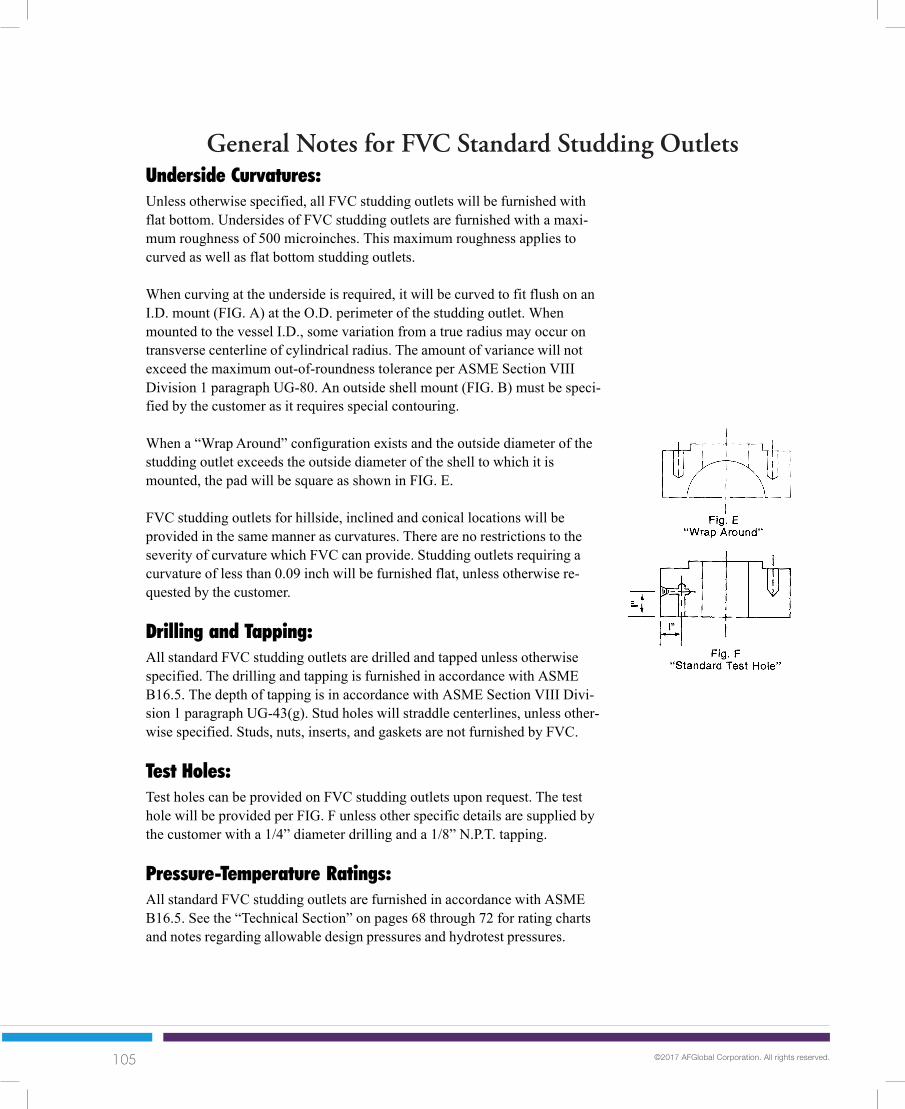
105 ©2017 AFGlobal Corporation. All rights reserved.
General Notes for FVC Standard Studding Outlets
51
Underside Curvatures:Unless otherwise specified, all FVC studding outlets will be furnished withflat bottom. Undersides of FVC studding outlets are furnished with a maxi-mum roughness of 500 microinches. This maximum roughness applies tocurved as well as flat bottom studding outlets.
When curving at the underside is required, it will be curved to fit flush on anI.D. mount (FIG. A) at the O.D. perimeter of the studding outlet. Whenmounted to the vessel I.D., some variation from a true radius may occur ontransverse centerline of cylindrical radius. The amount of variance will notexceed the maximum out-of-roundness tolerance per ASME Section VIIIDivision 1 paragraph UG-80. An outside shell mount (FIG. B) must be speci-fied by the customer as it requires special contouring.
When a “Wrap Around” configuration exists and the outside diameter of thestudding outlet exceeds the outside diameter of the shell to which it ismounted, the pad will be square as shown in FIG. E.
FVC studding outlets for hillside, inclined and conical locations will beprovided in the same manner as curvatures. There are no restrictions to theseverity of curvature which FVC can provide. Studding outlets requiring acurvature of less than 0.09 inch will be furnished flat, unless otherwise re-quested by the customer.
Drilling and Tapping:All standard FVC studding outlets are drilled and tapped unless otherwisespecified. The drilling and tapping is furnished in accordance with ASMEB16.5. The depth of tapping is in accordance with ASME Section VIII Divi-sion 1 paragraph UG-43(g). Stud holes will straddle centerlines, unless other-wise specified. Studs, nuts, inserts, and gaskets are not furnished by FVC.
Test Holes:Test holes can be provided on FVC studding outlets upon request. The testhole will be provided per FIG. F unless other specific details are supplied bythe customer with a 1/4” diameter drilling and a 1/8” N.P.T. tapping.
Pressure-Temperature Ratings:All standard FVC studding outlets are furnished in accordance with ASMEB16.5. See the “Technical Section” on pages 68 through 72 for rating chartsand notes regarding allowable design pressures and hydrotest pressures.
Notes continued on the following page.
General Notes for FVCStandard Studding Outlets

106 ©2017 AFGlobal Corporation. All rights reserved.
General Notes for FVC Standard Studding Outlets
52
Heat Treatment:All standard FVC connections CLASS 400 and above are supplied in thenormalized condition in accordance with the requirements of ASME SectionII. Additional heat treatment requirements can be furnished upon request.
Reinforcement:Particular attention must be paid to the area required for reinforcing an open-ing using a studding outlet because of the voids created by the tapped holes.Paragraph UG-37 of ASME Section VIII Division 1 addresses the planes ofreinforcement and the “F” factor. This reduction of available reinforcementmust not be overlooked. See the following table for area of various tappedholes. The area lost from the tapped holes can be provided by increasing the“T” dimension or the O.D. when required.
LOSS OF REINFORCEMENT DUE TO TAPPED HOLESTap Size (inches) Depth of Hole (inches) Area (sq. inches)
1/2 0.88 0.815/8 1.12 1.283/4 1.31 1.807/8 1.44 2.291 1.56 2.82
1 1/8 1.81 3.691 1/4 2.12 4.831 3/8 2.25 5.621 1/2 2.38 6.471 5/8 2.56 7.53 1 3/4 2.81 8.921 7/8 3.00 10.19
2 3.31 12.042 1/4 3.56 14.502 1/2 4.00 16.132 3/4 4.38 21.82
3 4.62 25.023 1/2 5.38 33.99
General Notes for FVCStandard Studding Outlets

107 ©2017 AFGlobal Corporation. All rights reserved.
Technical
59
SA-105* ** 0.35 (Max) 0.6-1.05 0.04 0.05 0.35 (Max) - - - - - -
SA-182-F1 0.28 (Max) 0.6-0.9 0.045 0.045 0.15-0.35 - - 0.44-0.65 - - -SA-182-F5 0.15 (Max) 0.3-0.6 0.03 0.03 0.5 (Max) 0.5 (Max) 4.0-6.0 0.44-0.65 - - -SA-182-F11 0.1-0.2 0.3-0.8 0.04 0.04 0.5-1.0 - 1.0-1.5 0.44-0.65 - - -SA-182-F12 0.1-0.2 0.3-0.8 0.04 0.04 0.1-0.6 - 0.8-1.25 0.44-0.65 - - -SA-182-F22 0.15 (Max) 0.3-0.6 0.04 0.04 0.5 (Max) - 2.0-2.5 0.87-1.13 - - -
SA-182-F304 0.08 (Max) 2.0 (Max) 0.04 0.03 1.0 (Max) 8.0-11.0 18.0-20.0 - - - -SA-182-F304L 0.035 (Max) 2.0 (Max) 0.04 0.03 1.0 (Max) 8.0-13.0 18.0-20.0 - - - -SA-182-F316 0.08 (Max) 2.0 (Max) 0.04 0.03 1.0 (Max) 10.0-14.0 16.0-18.0 2.0-3.0 - - -SA-182-F316L 0.035 (Max) 2.0 (Max) 0.04 0.03 1.0 (Max) 10.0-15.0 16.0-18.0 2.0-3.0 - - -SA-182-F321 0.08 (Max) 2.0 (Max) 0.04 0.03 1.0 (Max) 9.0-12.0 17.0 (Min) - - - -
SA-350-LF1 * 0.3 (Max) 1.35 (Max) 0.035 0.04 0.15-0.3 - - - - - -SA-350-LF2 * 0.3 (Max) 1.35 (Max) 0.035 0.04 0.15-0.3 - - - - - -SA-350-LF3 * 0.2 (Max) 0.9 (Max) 0.035 0.04 0.2-0.35 3.25-3.75 - - - - -
SA-508 GR2 0.27 (Max) 0.50-1.00 0.025 0.025 0.15-0.40 0.50-1.00 0.25-0.45 0.55-0.70 0.05 - -SA-508 GR3 0.25 (Max) 1.20-1.50 0.025 0.025 0.15-0.40 0.40-1.00 0.25 (Max) 0.45-0.60 0.05 - -
SA-765 GR2 0.30 (Max) 0.60-1.05 0.020 0.020 0.15-0.35 0.50 (Max) 0.40 (Max) 0.25 (Max) 0.05 0.05 0.35
SAE-4130 0.28-0.33 0.4-0.6 0.04 0.04 0.2-0.35 - 0.8-1.10 0.15-0.25 - - -
Material Specifications For FVC ProductsChemical Composition (%)
Specification C Mn P S Si Ni Cr Mo V Al Cu(Max) (Max) (Max)(Max) (Max)
Technical
* FVC stocks chemistries which comply with “Sour Service” requirements (NACE).** For each reduction of 0.01% below the specified carbon maximum (0.35%), an increase of 0.06% manganese above the specified
maximum (1.05%) will be permitted up to a maximum of 1.35%.Notes:1. The materials listed above are typical of FVC inventory and are subject to availability.2. Other materials can be provided based on special orders which may be subject to prior sale and quantity minimums.
ASME Material CompatibilityForging Spec. P.V.Q. Plate Spec. Pipe Spec. Fitting Spec.
SA-105 SA-285, SA-515 SA-53, SA-106 SA-234WPBSA-350-LF1 SA-515, SA-516 SA-333-GR 6 SA-420WPL6SA-350-LF2 SA-516 SA-333-GR 6 SA-420WPL6SA-350-LF3 SA-203-GR D SA-333-GR 3 SA-420WPL3
SA-182-F1 SA-204 SA-335-P1 SA-234-WP1SA-182-F5 SA-387-GR 5 SA-335-P5 SA-234-WP5SA-182-F11 SA-387-GR 11 SA-335-P11 SA-234-WP11SA-182-F12 SA-387-GR 12 SA-335-P12 SA-234-WP12SA-182-F22 SA-387-GR 22 SA-335-P22 SA-234-WP22
SA-182-F304 SA-240-304 SA-312-TP304 SA-403-WP304SA-182-F304L SA-240-304L SA-312-TP304L SA-403-WP304LSA-182-F316 SA-240-316 SA-312-TP316 SA-403-WP316SA-182-F316L SA-240-316L SA-312-TP316L SA-403-WP316LSA-182-F321 SA-240-321 SA-312-TP321 SA-403-WP321

108 ©2017 AFGlobal Corporation. All rights reserved.
Technical
60
Technical
General Notes: 1) All dimensions are in inches.
2) FVC connections are manufactured in accordance with the tolerances setforth by ASME B16.5.
3) Tolerances may be modified to meet customer requirements when specified.
DIA > 24 ± 0.12DIA < 24 ± 0.06
B.C. ± 0.06
0.25 R.F. ± 0.020.06 R.F. ± 0.03
SEEDETAIL “A”
SEEDETAIL “A”
SEEDETAIL “A”
NUT RELIEF + .0625- 0
NUT STOP + 0- .0625
BORE:SIZES 10” AND SMALLER
± 0.03SIZES 12” THROUGH 18”
± 0.06SIZES 20” AND LARGER
+ 0.12 - 0.06
BARREL O.D.:FOR ALL “HB” NECKS:
+0 -.0625FOR ALL OTHER STYLES: SIZES 4” AND SMALLER
+.09375 -.03125SIZES 5” AND LARGER
+.15625 -.03125
NL + 0.125- 0.03
± 2.5°
OA
L:FO
R S
TD L
EN
GTH
S±
.125
FOR
NO
N-S
TD+
.125
-0
FVC Connection Tolerances

109 ©2017 AFGlobal Corporation. All rights reserved.
Technical
61
Technical
FVC Connection Tolerances
Bevel dimension and tolerances are based on ASME B16.5. The above details will be providedunless otherwise specified. Other bevels are available upon request.
Note: Undercut dimensions and tolerances comply with ASME Section VIII Division1, Fig 2-4
FVC Welding Bevel Details
0.06 R.F. ± .0156250.25 R.F. ± 0.3125RTJ ± .03125
SIZES 18” AND SMALLER+ 0.12 - ZERO
SIZES 20” AND LARGER+ 0.19 - ZERO
SIZES 18” AND SMALLER0.25 RADIUS TOOL
SIZES 20” AND LARGER0.375 RADIUS TOOL
SIZES 18” AND SMALLER0.19 ± 0.03
SIZES 20” AND LARGER0.31 ± 0.03
DETAIL “A”

110 ©2017 AFGlobal Corporation. All rights reserved.
Technical
62
General Notes For FVC Flange Facings
FVC connections are available with numerous standard and special facings.The more popular standard facings are described on the following pages.Customers are requested to furnish details for any special facings desired.
The facing height and outside diameter are specified in the standard productdimensional tables. The serrations are spiral and are in accordance with therequirements of the latest issue of ASME B16.5 and MSS-SP6.
All pressure class flanges may be ordered flat faced. On 150# and 300# ratedflanges, the raised face normally furnished will be removed by machining. Theresulting minimum flange thickness will be 0.06 inch less than that specifiedas dimension “T” in the standard product dimensional tables. On flanges rated400# and above, the raised face normally furnished will also be removed bymachining. However, the resulting flange thickness will not be less than thespecified dimension “T”.
As an alternate, all flat face flanges may be ordered as “full-face”-”flat face”.In this case, 150# and 300# rated flanges will have a resulting minimumflange thickness of no less than that specified as dimension “T”. Any 400# andhigher rated flanges will be provided with a minimum flange thickness of thatspecified as dimension “T” plus 0.25 inch.
In all cases, the entire flange surface will be finished to a roughness not ex-ceeding 250 AARH, unless otherwise specified by the customer.
All options mentioned above are per ASME B16.5 Standards.
Except as otherwise specified, no finish machining will be performed onrough forgings. No holes will be drilled. A minimum of 0.12 inch will beprovided on all surfaces for customer machining. Facing heights exceedingthose of a standard raised face must be indicated.
The table on pages 64 and 65 gives the dimensions applicable to ring typejoint facings. The side walls of the gasket groove are finished to a surfaceroughness not exceeding 63 microinches.
The dimensional details of other standard facings are presented in thetable on the following page.
TechnicalTechnical
Raised Face:
Flat Face:
Rough Face:
RTJ:
Other StandardFacings:

111 ©2017 AFGlobal Corporation. All rights reserved.
Technical
63
FLGSize R S T U W X Y Z K L
½ 1.38 0.72 1.38 1.00 1.44 0.78 1.44 0.94 1.75 1.81¾ 1.69 0.94 1.69 1.31 1.75 1.00 1.75 1.25 2.06 2.121 2.00 1.19 1.88 1.50 2.06 1.25 1.94 1.44 2.25 2.44
1¼ 2.50 1.50 2.25 1.88 2.56 1.56 2.31 1.81 2.62 2.941½ 2.88 1.75 2.50 2.12 2.94 1.81 2.56 2.06 2.88 3.312 3.62 2.25 3.25 2.88 3.69 2.31 3.31 2.81 3.62 4.06
2½ 4.12 2.69 3.75 3.38 4.19 2.75 3.81 3.31 4.12 4.563 5.00 3.31 4.62 4.25 5.06 3.38 4.69 4.19 5.00 5.44
3½ 5.50 3.81 5.12 4.75 5.56 3.88 5.19 4.69 5.50 5.944 6.19 4.31 5.69 5.19 6.25 4.38 5.75 5.12 6.19 6.625 7.31 5.38 6.81 6.31 7.38 5.44 6.88 6.25 7.31 7.756 8.50 6.38 8.00 7.50 8.56 6.44 8.06 7.44 8.50 8.948 10.62 8.38 10.00 9.38 10.69 8.44 10.06 9.31 10.62 11.06
10 12.75 10.50 12.00 11.25 12.81 10.56 12.06 11.19 12.75 13.1912 15.00 12.50 14.25 13.50 15.06 12.56 14.31 13.44 15.00 15.4414 16.25 13.75 15.50 14.75 16.31 13.81 15.56 14.69 16.25 16.6916 18.50 15.75 17.62 16.75 18.56 15.81 17.69 16.69 18.50 18.9418 21.00 17.75 20.12 19.25 21.06 17.81 20.19 19.19 21.00 21.4420 23.00 19.75 22.00 21.00 23.06 19.81 22.06 20.94 23.00 23.4424 27.25 23.75 26.25 25.25 27.31 23.81 26.31 25.19 27.25 27.69
Notes:1. These dimensions apply to all ASME pressure classes except that the large facings are not available on Class 150 flanges.2. Facing heights and groove depths must be added to basic “T” dimensions but they are included in overall length “OAL”.
TechnicalTechnical
THIS TABLE LISTS THE DIMENSIONS FOR STANDARD MALE, FEMALE, TONGUE AND GROOVE FACINGSAVAILABLE ON ALL FVC CONNECTIONS.

112 ©2017 AFGlobal Corporation. All rights reserved.
Technical
64
Technical
Ring Type Joint FacingsR K
0.03 2.000.03 2.380.03 2.560.03 2.500.03 2.620.03 2.880.03 2.500.03 2.750.03 2.810.03 3.250.03 2.880.03 3.120.03 3.190.03 4.000.03 3.250.03 3.560.03 3.620.03 4.500.03 4.000.03 4.250.03 4.880.03 5.250.03 4.750.03 5.000.03 5.380.06 5.880.03 5.250.03 5.750.03 6.120.03 6.620.06 6.62
SIZE CLASS
300-600½ 900-1500
2500300-600
¾ 900-15002500150
1 300-600900-1500
2500150
300-6001¼ 900-1500
2500150
1½ 300-600900-1500
2500150
300-6002 900-1500
2500150
2½ 300-600900-1500
2500150
300-6003 900
15002500
P
R 11 1.344R 12 1.562R 13 1.688R 13 1.688R 14 1.750R 16 2.000R 15 1.875R 16 2.000R 16 2.000R 18 2.375R 17 2.250R 18 2.375R 18 2.375R 21 2.844R 19 2.562R 20 2.688R 20 2.688R 23 3.250R 22 3.250R 23 3.250R 24 3.750R 26 4.000R 25 4.000R 26 4.000R 27 4.250R 28 4.375R 29 4.500R 31 4.875R 31 4.875R 35 5.375R 32 5.000
E F
0.219 0.2810.250 0.3440.250 0.3440.250 0.3440.250 0.3440.250 0.3440.250 0.3440.250 0.3440.250 0.3440.250 0.3440.250 0.3440.250 0.3440.250 0.3440.312 0.4690.250 0.3440.250 0.3440.250 0.3440.312 0.4690.250 0.3440.312 0.4690.312 0.4690.312 0.4690.250 0.3440.312 0.4690.312 0.4690.375 0.5310.250 0.3440.312 0.4690.312 0.4690.312 0.4690.375 0.531
GROOVENUMBER
See notes on next page.
Ring Type Jointfacings are available onall FVC connections perASME B16.5
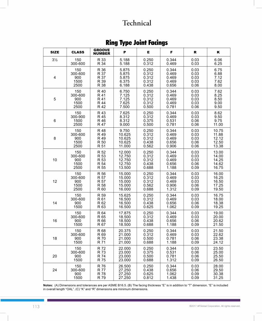
113 ©2017 AFGlobal Corporation. All rights reserved.
Technical
65
Technical
R K
0.03 6.060.03 6.250.03 6.750.03 6.880.03 7.120.03 7.620.06 8.000.03 7.620.03 8.250.03 8.500.03 9.000.06 9.500.03 8.620.03 9.500.06 9.750.06 11.000.03 10.750.03 11.880.03 12.120.06 12.500.06 13.380.03 13.000.03 14.000.03 14.250.06 14.620.09 16.750.03 16.000.03 16.250.03 16.500.06 17.250.09 19.500.03 16.750.03 18.000.06 18.380.09 19.250.03 19.000.03 20.000.06 20.620.09 21.500.03 21.500.03 22.620.06 23.380.09 24.120.03 23.500.06 25.000.06 25.500.09 26.500.03 28.000.06 29.500.09 30.380.09 31.25
SIZE CLASS
3½ 150300-600
150300-600
4 90015002500150
300-6005 900
15002500150
300-9006 1500
2500150
300-6008 900
15002500150
300-60010 900
15002500150
300-60012 900
15002500150
300-60014 900
1500150
300-60016 900
1500150
300-60018 900
1500150
300-60020 900
1500150
24 300-600900
1500
P
R 33 5.188R 34 5.188R 36 5.875R 37 5.875R 37 5.875R 39 6.375R 38 6.188R 40 6.750R 41 7.125R 41 7.125R 44 7.625R 42 7.500R 43 7.625R 45 8.312R 46 8.312R 47 9.000R 48 9.750R 49 10.625R 49 10.625R 50 10.625R 51 11.000R 52 12.000R 53 12.750R 53 12.750R 54 12.750R 55 13.500R 56 15.000R 57 15.000R 57 15.000R 58 15.000R 60 16.000R 59 15.625R 61 16.500R 62 16.500R 63 16.500R 64 17.875R 65 18.500R 66 18.500R 67 18.500R 68 20.375R 69 21.000R 70 21.000R 71 21.000R 72 22.000R 73 23.000R 74 23.000R 75 23.000R 76 26.500R 77 27.250R 78 27.250R 79 27.250
E F
0.250 0.3440.312 0.4690.250 0.3440.312 0.4690.312 0.4690.312 0.4690.438 0.6560.250 0.3440.312 0.4690.312 0.4690.312 0.4690.500 0.7810.250 0.3440.312 0.4690.375 0.5310.500 0.7810.250 0.3440.312 0.4690.312 0.4690.438 0.6560.562 0.9060.250 0.3440.312 0.4690.312 0.4690.438 0.6560.688 1.1880.250 0.3440.312 0.4690.312 0.4690.562 0.9060.688 1.3120.250 0.3440.312 0.4690.438 0.6560.625 1.0620.250 0.3440.312 0.4690.438 0.6560.688 1.1880.250 0.3440.312 0.4690.500 0.7810.688 1.1880.250 0.3440.375 0.5310.500 0.7810.688 1.3120.250 0.3440.438 0.6560.625 1.0620.812 1.438
GROOVENUMBER
Ring Type Joint Facings
Notes: (A) Dimensions and tolerances are per ASME B16.5. (B) The facing thickness “E” is in addition to “T” dimension. “E” is includedin overall length “OAL”. (C) “K” and “R” dimensions are minimum dimensions.

114 ©2017 AFGlobal Corporation. All rights reserved.
Technical
66
Technical
Nominal WeightPipe O.D. Pipe Wall I.D. perSize Sched. Thk. Foot
1/8 0.405
1/4 0.540
3/8 0.675
1/2 0.840
3/4 1.050
1 1.315
1¼ 1.660
1½ 1.900
2 2.375
2½ 2.875
Nominal WeightPipe O.D. Pipe Wall I.D. perSize Sched. Thk. Foot
3 3.500
3½ 4.000
4 4.500
5 5.563
6 6.625
8 8.625
10S 0.049 0.307 0.186*40 0.068 0.269 0.244
**80 0.095 0.215 0.31410S 0.065 0.410 0.330
*40 0.088 0.364 0.424**80 0.119 0.302 0.535
10S 0.065 0.545 0.423*40 0.091 0.493 0.567
**80 0.126 0.423 0.7385S 0.065 0.710 0.538
10S 0.083 0.674 0.671*40 0.109 0.622 0.850
**80 0.147 0.546 1.087160 0.188 0.464 1.310
XX-STG 0.294 0.252 1.7145S 0.065 0.920 0.684
10S 0.083 0.884 0.857*40 0.113 0.824 1.130
**80 0.154 0.742 1.473160 0.219 0.612 1.940
XX-STG 0.308 0.434 2.4405S 0.065 1.185 0.868
10S 0.109 1.097 1.404*40 0.133 1.049 1.678
* *80 0.179 0.957 2.171160 0.250 0.815 2.850
XX-STG 0.358 0.599 3.6595S 0.065 1.530 1.107
10S 0.109 1.442 1.806*40 0.140 1.380 2.272
**80 0.191 1.278 2.996160 0.250 1.160 3.764
XX-STG 0.382 0.896 5.2145S 0.065 1.770 1.274
10S 0.109 1.682 2.085*40 0.145 1.610 2.717
**80 0.200 1.500 3.631160 0.281 1.338 4.862
XX-STG 0.400 1.100 6.4085S 0.065 2.245 1.604
10S 0.109 2.157 2.638*40 0.154 2.067 3.652
**80 0.218 1.939 5.022160 0.344 1.687 7.450
XX-STG 0.436 1.503 9.0295S 0.083 2.709 2.48
10S 0.120 2.635 3.53*40 0.203 2.469 5.79
**80 0.276 2.323 7.66160 0.375 2.125 10.01
XX-STG 0.552 1.771 13.69
Properties of Pipe
5S 0.083 3.334 3.0310S 0.120 3.260 4.33
*40 0.216 3.068 7.57**80 0.300 2.900 10.25160 0.438 2.624 14.32
XX-STG 0.600 2.300 18.585S 0.083 3.834 3.47
10S 0.120 3.760 4.97*40 0.226 3.548 9.11
**80 0.318 3.364 12.515S 0.083 4.334 3.92
10S 0.120 4.260 5.61*40 0.237 4.026 10.79
**80 0.337 3.826 14.98120 0.438 3.624 19.00160 0.531 3.438 22.60
XX-STG 0.674 3.152 27.545S 0.109 5.345 6.35
10S 0.134 5.295 7.77*40 0.258 5.047 14.62
**80 0.375 4.813 20.78120 0.500 4.563 27.10160 0.625 4.313 32.96
XX-STG 0.750 4.063 38.555S 0.109 6.407 7.59
10S 0.134 6.357 9.29*40 0.280 6.065 18.97
**80 0.432 5.761 28.57120 0.562 5.501 36.40160 0.719 5.187 45.30
XX-STG 0.864 4.897 53.165S 0.109 8.407 10
10S 0.148 8.329 1320 0.250 8.125 2230 0.277 8.071 25
*40 0.322 7.981 2960 0.406 7.813 36
**80 0.500 7.625 43100 0.594 7.437 51120 0.719 7.187 61140 0.812 7.001 68160 0.906 6.813 75
XX-STG 0.875 6.875 72
* SCH 40, SCH 40S, and STD. WT. are the same 1/8” N.P.S.thru 10” N.P.S. inclusive
** SCH 80, SCH 80S, and X-STG are the same 1/8” N.P.S. thru8” N.P.S. inclusive
s Includes STD. WT.t Includes X-STG

115 ©2017 AFGlobal Corporation. All rights reserved.
Technical
67
Technical
Nominal WeightPipe O.D. Pipe Wall I.D. perSize Sched. Thk. Foot
10 10.750
12 12.750
14 14.000
16 16.000
Nominal WeightPipe O.D. Pipe Wall I.D. perSize Sched. Thk. Foot
18 18.000
20 20.000
24 24.000
Properties of Pipe
5S 0.165 17.670 3110S 0.188 17.624 3610 0.250 17.500 4720 0.312 17.375 5930 0.438 17.124 82
STD.WT. 0.375 17.250 7140 0.562 16.876 10560 0.750 16.500 138
X-STG 0.500 17.000 9380 0.938 16.124 171
100 1.156 15.688 208120 1.375 15.250 244140 1.562 14.876 275160 1.781 14.438 309
5S 0.188 19.624 4010S 0.218 19.564 4610 0.250 19.500 5320 0.375 19.250 7930 0.500 19.000 105
STD.WT. 0.375 19.250 7940 0.594 18.812 12360 0.812 18.376 167
X-STG 0.500 19.000 10580 1.031 17.938 209
100 1.281 17.438 256120 1.500 17.000 297140 1.750 16.500 342160 1.969 16.062 379
5S 0.218 23.564 5510S 0.250 23.500 6310 0.250 23.500 6320 0.375 23.250 9530 0.562 22.876 141
STD.WT. 0.375 23.250 9540 0.688 22.624 17160 0.969 22.062 238
X-STG 0.500 23.000 12580 1.219 21.562 297
100 1.531 20.938 367120 1.812 20.376 429140 2.062 19.876 484160 2.344 19.312 542
5S 0.134 10.482 1510S 0.165 10.420 1920 0.250 10.250 2830 0.307 10.136 34
*40 0.365 10.020 4060 0.500 9.750 5580S 0.500 9.750 5580 0.594 9.562 64
100 0.719 9.312 77120 0.844 9.062 89140 1.000 8.750 104160 1.125 8.500 116
XX-STG 1.000 8.750 1045S 0.156 12.438 21
10S 0.180 12.390 2420 0.250 12.250 3330 0.330 12.090 4440S 0.375 12.000 5040 0.406 11.938 5460 0.562 11.626 7380S 0.500 11.750 6580 0.688 11.374 89
100 0.844 11.062 108120 1.000 10.750 126140 1.125 10.500 140160 1.312 10.126 161
XX-STG 1.000 10.750 1265S 0.156 13.688 23
10S 0.188 13.624 2810 0.250 13.500 3720 0.312 13.376 4630 0.375 13.250 55
STD.WT. 0.375 13.250 5540 0.438 13.124 6360 0.594 12.812 85
X-STG 0.500 13.000 7280 0.750 12.500 107
100 0.938 12.124 131120 1.094 11.812 151140 1.250 11.500 171160 1.406 11.188 190
5S 0.165 15.670 2810S 0.188 15.624 3210 0.250 15.500 4220 0.312 15.375 5230 0.375 15.250 63
STD.WT. 0.375 15.250 6340 0.500 15.000 8360 0.656 14.688 108
X-STG 0.500 15.000 8380 0.844 14.312 137
100 1.031 13.938 165120 1.219 13.562 193140 1.438 13.124 224160 1.594 12.812 245
Notes:A) All dimensions are in inches.B) All weights are in pounds.C) Dimensions for STD WT., X-STG, XX-STG, SCH 10, 20, 30,
40, 60, 80, 100, 120, 140 and 160 are in conformance withANSI B36.10.
D) Dimensions for SCH 5S, 10S, 40S and 80S are in conform-ance with ANSI B36.19.
s
t
t

116 ©2017 AFGlobal Corporation. All rights reserved.
Technical
68
Material SeeGroup Material Notes
A-105 a,h,j1.1 A-515-70 a,h
A-516-70 a,gA-350-LF2,A-537 C1.1 d
1.2 A-203-B, A-203-E a,hA-350-LF3 dA-515-60 a,h
1.4 A-516-60 a,gA-350-LF1 d
1.5 A-182-F1, A-204-A, A-204-B b,h1.7 A-204-C g
A-182-F2 h1.9 A-182-F11 C1.2, A-182-F12 c,k
A-387-11 C1.2 c1.10 A-182-F22 C1.3, A-387-22 C1.2 c1.13 A-182-F5A, A-182-F5 -1.14 A-182-F9 -
Technical
Pressure-Temperature RatingsTHE FOLLOWING TABLE AND NOTES DETAIL THE MATERIALS FOR THE ASME B16.5
PRESSURE-TEMPERATURE CHARTS:
General Note:Plate materials are listed only for use as blind flanges. For more details see ASME B16.5.
Notes:a. Permissible but not recommended for prolonged use above about 800°F (425°C).b. Permissible but not recommended for prolonged use above about 850°F (455°C).c. Permissible but not recommended for prolonged use above about 1100°F (593°C).d. Not to be used over 650°F (343°C).f. Not to be used over 800°F (425°C).g. Not to be used over 850°F (455°C).h. Not to be used over 1000°F (540°C).i. For service temperature 1050°F (566°C) and above, assurance must be provided that grain size is not finer than ASTM No. 6.j. Only killed steel may be used above 850°F (455°C).k. Use normalized and tempered material only.l. At temperatures over 1000°F (540°C), use only when the carbon content is 0.04 percent or higher.m. For temperatures over 1000°F (540°C), use only if the material is heat treated by heating it to a temperature of at least 1900°F
(1040°C) and quenching in water or rapidly cooling by other means.n. For service temperatures of 1050°F (566°C) and above, assurance must be provided that grain size is not finer than ASTM No. 6.o. To be used only for Class 150 and Class 300 flanges.
Material SeeGroup Material Notes
A-182-F304 l2.1 A-182-F304H -
A-240-304, A-240-304H l,mA-182-F316 l
2.2 A-182-F316H -A-240-316, A-240-316H, A-240-317 l,m
2.3 A-182-F304L, A-240-304L fA-182-F316L, A-240-316L gA-182-F321 h,l
2.4 A-240-321 h,l,mA-182-F321H -A-240-321H mA-182-F347 h,iA-240-347 h,l,m
2.5 A-182-F347H -A-240-347H mA-182-F348 h,lA-240-348 h,l,mA-182-F348H -A-240-348H m
2.6 A-240-309S, A-240-309H l,m2.7 A-182-F310, A-240-310S, A-240-310H i,l,n

117 ©2017 AFGlobal Corporation. All rights reserved.
Technical
69
s
Technical
MaterialGroup 1.1* 1.2 1.4 1.5 1.7 1.9 1.10 1.13 1.14 2.1 2.2 2.3 2.4 2.5 2.6 2.7
-20° to 100° 285 290 235 265 290 290 290 290 290 275 275 230 275 275 260 260 100°200° 260 260 215 260 260 260 260 260 260 235 240 195 235 245 230 230 200°300° 230 230 210 230 230 230 230 230 230 205 215 175 210 225 220 220 300°400° 200 200 200 200 200 200 200 200 200 180 195 160 190 200 200 200 400°500° 170 170 170 170 170 170 170 170 170 170 170 145 170 170 1.70 170 500°600° 140 140 140 140 140 140 140 140 140 140 140 140 140 140 140 140 600°650° 125 125 125 125 125 125 125 125 125 125 125 125 125 125 125 125 650°700° 110 110 110 110 110 110 110 110 110 110 110 110 110 110 110 110 700°750° 95 95 95 95 95 95 95 95 95 95 95 95 95 95 95 95 750°800° 80 80 80 80 80 80 50 80 80 80 80 80 80 80 80 80 800°850° 65 65 65 65 65 65 65 65 65 65 65 65 65 65 65 65 850°900° 50 50 50 50 50 50 50 50 50 50 50 - 50 50 50 50 900°950° 35 35 35 35 35 35 35 35 35 35 35 - 35 35 35 35 950°1000° 20 20 20 20 20 20 20 20 20 20 20 - 20 20 20 20 1000°
Notes: 1. See temperature notes for all materials (page 68).2. Pressures are in pounds per square inch, gage (psig)t 316L ONLY* material Group 1.1 includes: SA-105, SA-515-70, SA-516-70, SA-350-LF2, SA-537 C1.1
MaterialGroup 1.1 1.2 1.4 1.5 1.7 1.9 1.10 1.13 1.14 2.1 2.2 2.3 2.4 2.5 2.6 2.7
-20° to 100° 740 750 620 695 750 750 750 750 750 720 720 600 720 720 670 670 100°200° 675 750 560 680 750 710 715 750 750 600 620 505 610 635 605 605 200°300° 655 730 550 655 730 675 675 730 730 530 560 455 545 590 570 570 300°400° 635 705 530 640 705 660 650 705 705 470 515 415 495 555 535 535 400°500° 600 665 500 620 665 640 640 665 665 435 480 380 460 520 505 505 500°600° 550 605 455 605 605 605 605 605 605 415 450 360 435 490 480 480 600°650° 535 590 450 590 590 590 590 590 590 410 445 350 430 480 465 465 650°700° 535 570 450 570 570 570 570 570 570 405 430 345 420 470 455 455 700°750° 505 505 445 530 530 530 530 530 530 400 425 335 415 460 445 445 750°800° 410 410 370 510 510 510 510 500 510 395 415 330 415 455 435 435 800°850° 270 270 270 485 485 485 485 440 485 390 405 320 410 445 425 425 850°900° 170 170 170 450 450 450 450 355 450 385 395 - 405 430 415 415 900°950° 105 105 105 280 345 380 380 260 370 375 385 - 385 385 385 385 950°1000° 50 50 50 165 215 225 270 190 290 325 365 - 355 365 335 350 1000°1050° 190 140 200 140 190 310 360 - 345 360 290 335 1050°1100° 95 115 105 115 260 325 - 300 325 225 290 1100°1150° 50 105. 70 75 195 275 - 235 275 170 245 1150°1200° 35 55 45 50 155 205 - 180 170 130 205 1200°1250° 110 180 - 140 125 100 160 1250°1300° 85 140 - 105 95 80 120 1300°1350° 60 105 - 80 70 60 80 1350°1400° 50 75 - 60 50 45 55 1400°1450° 35 60 - 50 40 30 40 1450°1500° 25 40 - 40 35 25 25 1500°
t 316L ONLYs Material Group 1.1includes: SA-105,SA-515-70, SA-516-70,SA-350-LF2, SA-537 C1.1
Notes:1. See temperature notes for all materials (page 68)2. Pressures are in pounds per square inch, gage (psig)
Pressure-Temperature Ratings Class 300
Tem
pera
ture
(Fa
hren
heit
) Temperature (Fahrenheit)
t
Pressure-Temperature Ratings Class 150Te
mpe
ratu
re (
Fahr
enhe
it) Tem
perature (Fahrenheit)
t

118 ©2017 AFGlobal Corporation. All rights reserved.
Technical
70
Technical
t 316L ONLYs Material Group 1.1includes: SA-105,SA-515-70, SA-516-70,SA-350-LF2, SA-537 C1.1
Notes:1. See temperature notes for all materials (page 68)2. Pressures are in pounds per square inch, gage (psig)
Pressure-Temperature Ratings Class 400
Tem
pera
ture
(Fa
hren
heit
) Temperature (Fahrenheit)
t
Pressure-Temperature Ratings Class 600
Tem
pera
ture
(Fa
hren
heit
) Temperature (Fahrenheit)
t
s
s
t 316L ONLYs Material Group 1.1includes: SA-105,SA-515-70, SA-516-70,SA-350-LF2, SA-537 C1.1
Notes:1. See temperature notes for all materials (page 68)2. Pressures are in pounds per square inch, gage (psig)
MaterialGroup 1.1 1.2 1.4 1.5 1.7 1.9 1.10 1.13 1.14 2.1 2.2 2.3 2.4 2.5 2.6 2.7
-20° to 100° 990 1000 825 925 1000 1000 1000 1000 1000 960 960 800 960 960 895 895 100°200° 900 1000 750 905 1000 950 955 1000 1000 800 825 675 815 850 805 805 200°300° 875 970 730 870 970 895 905 970 970 705 745 605 725 785 760 760 300°400° 845 940 705 855 940 880 865 940 940 630 685 550 660 740 710 710 400°500° 800 885 665 830 885 855 855 885 885 585 635 510 610 690 670 670 500°600° 730 805 610 805 805 805 805 805 805 555 600 480 585 655 635 635 600°650° 715 785 600 785 785 785 785 785 785 545 590 470 570 640 620 620 650°700° 710 755 600 755 755 755 755 755 755 540 575 460 560 625 610 610 700°750° 670 670 590 710 710 710 710 710 710 530 565 450 555 615 595 595 750°800° 550 550 495 675 675 675 675 665 675 525 555 440 550 610 580 580 800°850° 355 355 355 650 650 650 650 585 650 520 540 430 545 590 565 565 850°900° 230 230 230 600 600 600 600 470 600 510 525 - 540 575 555 555 900°950° 140 140 140 375 460 505 505 350 495 500 515 - 515 515 515 515 950°
1000° 70 70 70 220 285 300 355 255 390 430 485 - 475 485 450 465 1000°1050° 250 185 265 190 250 410 480 - 460 480 390 445 1050°1100° 130 150 140 150 345 430 - 400 430 300 390 1100°1150° 70 140 90 100 260 365 - 315 365 230 330 1150°1200° 45 75 60 70 205 275 - 240 230 175 275 1200°1250° 145 245 - 185 165 135 215 1250°1300° 110 185 - 140 125 105 160 1300°1350° 85 140 - 110 90 80 105 1350°1400° 65 100 - 80 70 60 75 1400°1450° 45 80 - 65 55 40 50 1450°1500° 30 55 - 50 45 30 30 1500°
MaterialGroup 1.1 1.2 1.4 1.5 1.7 1.9 1.10 1.13 1.14 2.1 2.2 2.3 2.4 2.5 2.6 2.7
-20° to 100° 1480 1500 1235 1390 1500 1500 1500 1500 1500 1440 1440 1200 1440 1440 1345 1345 100°200° 1350 1500 1125 1360 1500 1425 1430 1500 1500 1200 1240 1015 1220 1270 1210 1210 200°300° 1315 1455 1095 1305 1455 1345 1355 1455 1455 1055 1120 910 1090 1175 1140 1140 300°400° 1270 1410 1060 1280 1410 1315 1295 1410 1410 940 1030 825 990 1110 1065 1065 400°500° 1200 1330 995 1245 1330 1285 1280 1330 1330 875 955 765 915 1035 1010 1010 500°600° 1095 1210 915 1210 1210 1210 1210 1210 1210 830 905 720 875 985 955 955 600°650° 1075 1175 895 1175 1175 1175 1175 1175 1175 815 890 700 855 960 930 930 650°700° 1065 1135 895 1135 1135 1135 1135 1135 1135 805 865 685 840 935 910 910 700°750° 1010 1010 885 1065 1065 1065 1065 1065 1065 795 845 670 830 920 895 895 750°800° 825 825 740 1015 1015 1015 1015 995 1015 790 830 660 825 910 870 870 800°850° 535 5.35 535 975 975 975 975 880 975 780 810 645 815 860 850 850 850°900° 345 345 345 900 900 900 900 705 900 770 790 - 810 865 830 830 900°950° 205 205 205 560 685 755 755 520 740 750 775 - 775 775 775 775 950°
1000° 105 105 105 330 425 445 535 385 585 645 725 - 715 725 670 700 1000°1050° 380 275 400 280 380 620 720 - 695 720 585 665 1050°1100° 190 225 205 225 515 645 - 605 645 445 585 1100°1150° 105 205 140 150 390 550 - 475 550 345 495 1150°1200° 70 110 90 105 310 410 - 365 345 260 410 1200°1250° 220 365 - 280 245 200 325 1250°1300° 165 275 - 210 185 160 240 1300°1350° 125 205 - 165 135 115 160 1350°1400° 90 150 - 125 105 90 110 1400°1450° 70 115 - 95 80 60 75 1450°1500° 50 85 - 75 70 50 50 1500°

119 ©2017 AFGlobal Corporation. All rights reserved.
Technical
71
Technical
t 316L ONLYs Material Group 1.1includes: SA-105,SA-515-70, SA-516-70,SA-350-LF2, SA-537 C1.1
Notes:1. See temperature notes for all materials (page 68)2. Pressures are in pounds per square inch, gage (psig)
Pressure-Temperature Ratings Class 900Te
mpe
ratu
re (
Fahr
enhe
it) Tem
perature (Fahrenheit)
t
Pressure-Temperature Ratings Class 1500
Tem
pera
ture
(Fa
hren
heit
) Temperature (Fahrenheit)
t
s
s
t 316L ONLYs Material Group 1.1includes: SA-105,SA-515-70, SA-516-70,SA-350-LF2, SA-537 C1.1
Notes:1. See temperature notes for all materials (page 68)2. Pressures are in pounds per square inch, gage (psig)
MaterialGroup 1.1 1.2 1.4 1.5 1.7 1.9 1.10 1.13 1.14 2.1 2.2 2.3 2.4 2.5 2.6 2.7
-20° to 100° 2220 2250 1850 2085 2250 2250 2250 2250 2250 2160 2160 1800 2160 2160 2015 2015 100°200° 2025 2250 1685 2035 2250 2135 2150 2250 2250 1800 1860 1520 1830 1910 1815 1815 200°300° 1970 2185 1640 1955 2185 2020 2030 2185 2185 1585 1680 1360 1635 1765 1705 1705 300°400° 1900 2115 1585 1920 2115 1975 1945 2115 2115 1410 1540 1240 1485 1665 1600 1600 400°500° 1795 1995 1495 1865 1995 1925 1920 1995 1995 1310 1435 1145 1375 1555 1510 1510 500°600° 1640 1815 1370 1815 1815 1815 1815 1815 1815 1245 1355 1080 1310 1475 1435 1435 600°650° 1610 1765 1345 1765 1765 1765 1765 1765 1765 1225 1330 1050 1280 1440 1395 1395 650°700° 1600 1705 1345 1705 1705 1705 1705 1705 1705 1210 1295 1030 1260 1405 1370 1370 700°750° 1510 1510 1325 1595 1595 1595 1595 1595 1595 1195 1270 1010 1245 1385 1340 1340 750°800° 1235 1235 1110 1525 1525 1525 1525 1490 1525 1180 1245 985 1240 1370 1305 1305 800°850° 805 805 805 1460 1460 1460 1460 1315 1460 1165 1215 965 1225 1330 1275 1275 850°900° 515 515 515 1350 1350 1350 1350 1060 1350 1150 1180 - 1215 1295 1245 1245 900°950° 310 310 310 845 1030 1130 1130 780 1110 1125 1160 - 1160 1160 1160 1160 950°
1000° 155 155 155 495 640 670 805 575 875 965 1090 - 1070 1090 1010 1050 1000°1050° 565 410 595 420 565 925 1080 - 1040 1080 875 1000 1050°1100° 290 340 310 340 770 965 - 905 965 670 875 1100°1150° 155 310 205 225 585 825 - 710 825 515 740 1150°1200° 105 165 135 155 465 620 - 545 515 390 620 1200°1250° 330 545 - 420 370 300 485 1250°1300° 245 410 - 320 280 235 360 1300°1350° 185 310 - 245 205 175 235 1350°1400° 145 225 - 185 155 135 165 1400°1450°’ 105 175 - 145 125 95 115 1450°1500° 70 125 - 115 105 70 70 1500°
MaterialGroup 1.1 1.2 1.4 1.5 1.7 1.9 1.10 1.13 1.14 2.1 2.2 2.3 2.4 2.5 2.6 2.7
-20° to 100° 3705 3750 3085 3470 3750 3750 3750 3750 3750 3600 3600 3000 3600 3600 3360 3360 100°200° 3375 3750 2810 3395 3750 3560 3580 3750 3750 3000 3095 2530 3050 3180 3025 3025 200°300° 3280 3640 2735 3260 3640 3365 3385 3640 3640 2640 2795 2270 2725 2940 2845 2845 300°400° 3170 3530 2645 3200 3530 3290 3240 3530 3530 2350 2570 2065 2470 2770 2665 2665 400°500° 2995 3325 2490 3105 3325 3210 3200 3325 3325 2185 2390 1910 2290 2590 2520 2520 500°600° 2735 3025 2285 3025 3025 3025 3025 3025 3025 2075 2255 1800 2185 2460 2390 2390 600°650° 2685 2940 2245 2940 2940 2940 2940 2940 2940 2040 2220 1750 2135 2400 2330 2330 650°700° 2665 2840 2245 2840 2840 2840 2840 2840 2840 2015 2160 1715 2100 2340 2280 2280 700°750° 2520 2520 2210 2660 2660 2660 2660 2660 2660 1990 2110 1680 2075 2305 2230 2230 750°800° 2060 2060 1850 2540 2540 2540 2540 2485 2540 1970 2075 1645 2065 2280 2170 2170 800°850° 1340 1340 1340 2435 2435 2435 2435 2195 2435 1945 2030 1610 2040 2220 2125 2125 850°900° 860 860 860 2245 2245 2245 2245 1765 2245 1920 1970 - 2030 2160 2075 2075 900°950° 515 515 515 1405 1715 1885 1885 1305 1850 1870 1930 - 1930 1930 1930 1930 950°
1000° 260 260 260 825 1065 1115 1340 960 1460 1610 1820 - 1785 1820 1680 1750 1000°1050° 945 685 995 705 945 1545 1800 - 1730 1800 1460 1665 1050°1100° 480 565 515 565 1285 1610 - 1510 1610 1115 1460 1100°1150° 260 515 345 380 980 1370 - 1185 1370 860 1235 1150°1200° 170 275 225 260 770 1030 - 910 855 650 1030 1200°1250° 550 910 - 705 615 495 805 1250°1300° 410 685 - 530 465 395 600 1300°1350° 310 515 - 410 345 290 395 1350°1400° 240 380 - 310 255 225 275 1400°1450° 170 290 - 240 205 155 190 1450°1500° 120 205 - 190 170 120 120 1500°
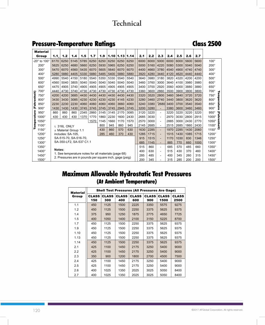
120 ©2017 AFGlobal Corporation. All rights reserved.
Technical
72
Technical
t 316L ONLYs Material Group 1.1includes: SA-105,SA-515-70, SA-516-70,SA-350-LF2, SA-537 C1.1
Notes:1. See temperature notes for all materials (page 68)2. Pressures are in pounds per square inch, gage (psig)
Pressure-Temperature Ratings Class 2500Te
mpe
ratu
re (
Fahr
enhe
it) Tem
perature (Fahrenheit)
t
s
MaterialShell Test Pressures (All Pressures Are Gage)
Group CLASS CLASS CLASS CLASS CLASS CLASS CLASS150 300 400 600 900 1500 2500
1.1 450 1125 1500 2225 3350 5575 92751.2 450 1125 1500 2250 3375 5625 93751.4 375 950 1250 1875 2775 4650 77251.5 400 1050 1400 2100 3150 5225 87001.7 450 1125 1500 2250 3375 5625 93751.9 450 1125 1500 2250 3375 5625 93751.10 450 1125 1500 2250 3375 5625 93751.13 450 1125 1500 2250 3375 5625 93751.14 450 1125 1500 2250 3375 5625 93752.1 425 1100 1450 2175 3250 5400 90002.2 425 1100 1450 2175 3250 5400 90002.3 350 900 1200 1800 2700 4500 75002.4 425 1100 1450 2175 3250 5400 90002.5 425 1100 1450 2175 3250 5400 90002.6 400 1025 1350 2025 3025 5050 84002.7 400 1025 1350 2025 3025 5050 8400
Maximum Allowable Hydrostatic Test Pressures(At Ambient Temperature)
MaterialGroup 1.1 1.2 1.4 1.5 1.7 1.9 1.10 1.13 1.14 2.1 2.2 2.3 2.4 2.5 2.6 2.7
-20° to 100° 6170 6250 5145 5785 6250 6250 6250 6250 6250 6000 6000 5000 6000 6000 5600 5600 100°200° 5625 6250 4680 5660 6250 5930 5965 6250 6250 5000 5160 4220 5080 5300 5040 5040 200°300° 5470 6070 4560 5435 6070 5605 5640 6070 6070 4400 4660 3780 4540 4900 4740 4740 300°400° 5280 5880 4405 5330 5880 5485 5400 5880 5880 3920 4280 3440 4120 4620 4440 4440 400°500° 4990 5540 4150 5180 5540 5350 5330 5540 5540 3640 3980 3180 3820 4320 4200 4200 500°600° 4560 5040 3805 5040 5040 5040 5040 5040 5040 3460 3760 3000 3640 4100 3980 3980 600°650° 4475 4905 3740 4905 4905 4905 4905 4905 4905 3400 3700 2920 3560 4000 3880 3880 650°700° 4440 4730 3740 4730 4730 4730 4730 4730 4730 3360 3600 2860 3500 3900 3800 3800 700°750° 4200 4200 3685 4430 4430 4430 4430 4430 4430 3320 3520 2800 3460 3840 3720 3720 750°800° 3430 3430 3085 4230 4230 4230 4230 4145 4230 3280 3460 2740 3440 3800 3620 3620 800°850° 2230 2230 2230 4060 4060 4060 4060 3660 4060 3240 3380 2680 3400 3700 3540 3540 850°900° 1430 1430 1430 3745 3745 3745 3745 2945 3745 3200 3280 - 3380 3600 3460 3460 900°950° 860 860 860 2345 2860 3145 3145 2170 3085 3120 3220 - 3220 3220 3220 3220 950°
1000° 430 430 430 1370 1770 1860 2230 1600 2430 2685 3030 - 2970 3030 2800 2915 1000°1050° 1570 1145 1660 1170 1570 2570 3000 - 2885 3000 2430 2770 1050°1100° 800 945 860 945 2145 2685 - 2515 2685 1860 2430 1100°1150° 430 860 570 630 1630 2285 - 1970 2285 1430 2060 1150°1200° 285 460 370 430 1285 1715 - 1515 1430 1085 1715 1200°1250° 915 1515 - 1170 1030 830 1346 1250°1300° 685 1145 - 885 770 660 1000 1300°1350° 515 860 - 685 570 485 660 1350°1400° 400 630 - 515 430 370 460 1400°1450° 285 485 - 400 345 260 315 1450°1500° 200 345 - 315 285 200 200 1500°

121 ©2017 AFGlobal Corporation. All rights reserved.
Technical
73
Technical
½ 13 0.126 0.875 0.969 0.484 0.8755/8 11 0.202 1.063 1.175 0.609 1.063¾ 10 0.302 1.250 1.383 0.734 1.2507/8 9 0.419 1.438 1.589 0.859 1.4381 8 0.551 1.625 1.796 0.984 1.625
1 1/8 8 0.728 1.813 2.002 1.109 1.8131¼ 8 0.929 2.000 2.209 1.219 2.000
1 3/8 8 1.155 2.188 2.416 1.344 2.1881½ 8 1.405 2.375 2.622 1.469 2.375
1 5/8 8 1.680 2.563 2.828 1.594 2.5631¾ 8 1.980 2.750 3.035 1.719 2.750
1 7/8 8 2.300 2.938 3.242 1.844 2.9382 8 2.650 3.125 3.449 1.969 3.125
2¼ 8 3.420 3.500 3.862 2.203 3.5002½ 8 4.290 3.875 4.275 2.453 3.8752¾ 8 5.260 4.250 4.688 2.703 4.2503 8 6.320 4.625 5.102 2.953 4.625
3¼ 8 7.490 5.000 5.515 3.188 5.0003½ 8 8.750 5.375 5.928 3.438 5.3753¾ 8 10.110 5.750 6.341 3.688 5.7504 8 11.570 6.125 6.755 3.938 6.125
Bolting MaterialsNominal Specification Grade ApplicationComposition Number
Carbon and Low Alloy SteelsC SA-307 B StructuralC SA-325 Type 1, 2, 3 StructuralC SA-354 BC, BD High Strength Service
(650°F max.)Cr-Mo SA-193 65 High Strength Service
(1200°F max.)Cr-Mo SA-193 B7 High Strength Service
(1000°F max.)Cr-Mo-V SA-193 B16 High Strength Service
(1100°F max.)Cr-Mo SA-320 L7 Low Temperature Service
High Alloy SteelsCr-Ni SA-193 B8, B8M Stainless Steel FlangesCr-Ni SA-320 B8, B8M Structural
Cr-Ni-Mo SA-453 660 High Strength Stainless Steel
Flange Bolting InformationDimensions of Bolts with Heavy Hex Heads and Nuts (ASME B18.2)
FVC NutNom. Stop Dia. =
Bolt Threads Root Across Across Nut Flange BoltSize Per Inch Area Flats Corners Thick. Circle Less:
Thread Dimensions Nut Dimensions

122 ©2017 AFGlobal Corporation. All rights reserved.
Technical
74
Technical
atmospheres .................. ft of water (at 4° C) ........ 33.90atmospheres .................. in of mercury (at 0° C) ... 29.92atmospheres .................. kgs/sq cm ....................... 1.0333atmospheres .................. pounds/sq in ................... 14.70
bars ................................ atmospheres .................. 0.9869btu .................................. foot-lbs ........................... 778.3btu .................................. joules .............................. 1,054.8btu .................................. kilowatt-hrs ..................... 2.928 x 10⁻⁴
calories, gram (mean) ... btu (mean) ...................... 3.9685 x 10⁻³
centigrade ...................... fahrenheit ....................... (C°x9/5) + 32centimeters .................... feet ................................. 3.281 x 10⁻²
centimeters .................... inches ............................. 0.3937centimeters .................... kilometers ....................... 10-5
centimeters .................... meters ............................ 0.01centimeters .................... millimeters ...................... 10.0cubic centimeters ........... cu feet ............................ 3.531 x 10⁻⁵
cubic centimeters ........... cu inches ........................ 0.06102cubic centimeters ........... cu meters ....................... 10-6
cubic centimeters ........... gallons (U.S. liq) ............. 2.642 x 10⁻⁴
cubic centimeters ........... liters ................................ 0.001cubic feet ....................... cu inches ........................ 1,728.0cubic feet ....................... cu meters ....................... 0.02832cubic feet ....................... gallons (U.S. liq) ............. 7.48052cubic feet ....................... liters ................................ 28.32cubic inches ................... cu cms ............................ 16.39cubic inches ................... cu feet ............................ 5.787 x 10⁻⁴
cubic inches ................... cu meters ....................... 1.639 x 10⁻⁵
cubic inches ................... gallons ............................ 4.329 x 10⁻³
cubic meters .................. cu cms ............................ 106
cubic meters .................. cu feet ............................ 35.31cubic meters .................. cu inches ........................ 61,023.0cubic meters .................. gallons (u.s. liq) .............. 264.2cubic meters .................. liters ................................ 1,000.0
dynes .............................. joules/cm ........................ 10-7
dynes .............................. joules/meter (newtons) .. 10-5
dynes .............................. kilograms ........................ 1.020 x 10⁻⁶
dynes .............................. poundals ......................... 7.233 x 10⁻⁵
dynes .............................. pounds ........................... 2.248 x 10⁻⁶
ergs ................................ BTU ................................ 9.480 x 10⁻¹¹
ergs ................................ foot-pounds .................... 7.367 x 10⁻⁸
ergs ................................ joules .............................. 10-7
ergs/sec ......................... horsepower .................... 1.341 x 10⁻¹⁰
feet ................................. centimeters .................... 30.48feet ................................. meters ............................ 0.3048feet ................................. millimeters ...................... 304.8feet ................................. inches ............................. 12.0feet of water ................... atmospheres .................. 0.02950feet of water ................... in of mercury .................. 0.8826feet of water ................... pounds/sq ft ................... 62.43feet of water ................... poundsisq in ................... 0.4335fahrenheit ....................... centigrade ...................... (°F- 32) x 5/9foot-pounds .................... BTU ................................ 1.286 x 10⁻³
foot-pounds .................... ergs ................................ 1.356 x 10⁷
foot-pounds .................... joules .............................. 1.356foot-pounds .................... kilowatt-hrs ..................... 3.766 x 10⁻⁷
gallons ............................ cu cms ............................ 3,785.0gallons ............................ cu feet ............................ 0.1337gallons ............................ cu inches ........................ 231.0gallons ............................ cu meters ....................... 3.785 x 10⁻³
gallons ............................ liters ................................ 3.785gallons (liq Br. Imp.) ...... gallons (U.S. liq) ............. 1.20095gallons (U.S.) ................. gallons (Imp.) ................. 0.83267gallons of water ............. pounds of water ............. 8.3453grams ............................. dynes .............................. 980.7grams ............................. kilograms ........................ 0.001grams ............................. milligrams ....................... 1,000.0grams ............................. ounces(avdp) ................. 0.03527grams ............................. ounces (troy) .................. 0.03215grams ............................. poundals ......................... 0.07093grams ............................. pounds ........................... 2.205 x 10⁻³
grams/cu cm .................. pounds/cu ft ................... 62.43grams/cu cm .................. pounds/cu in ................... 0.03613grams/sq cm .................. pounds/sq ft ................... 2.0481
horsepower .................... BTU/min ......................... 42.44horsepower .................... foot-lbs/min .................... 33,000.0horsepower .................... foot-lbs/sec .................... 550.0horsepower .................... kilowatts ......................... 0.7457horsepower .................... watts ............................... 745.7
inches ............................. centimeters .................... 2.540inches ............................. meters ............................ 2.540 x 10⁻²
inches ............................. millimeters ...................... 25.40inches ............................. mils ................................. 1,000.0inches ............................. feet ................................. 0.0833inches of mercury .......... atmospheres .................. 0.03342inches of mercury .......... inches of water ............... 13.6inches of mercury .......... feet of water ................... 1.1333inches of mercury .......... kgs/sq cm ....................... 0.03453inches of mercury .......... kgs/sq meter .................. 345.3inches of mercury .......... pounds/sq ft ................... 70.73inches of mercury .......... pounds/sq in ................... 0.4912inches of water (at 4°C) . atmospheres .................. 2.458 x 10⁻³
inches of water (at 4°C) . inches of mercury .......... 0.07355inches of water (at 4°C) . kgs/sq cm ....................... 2.540 x 10⁻³
inches of water (at 4°C) . Ounces/sq in .................. 0.5781inches of water (at 4°C) . pounds/sq ft ................... 5.204inches of water (at 4°C) . pounds/sq In ................... 0.03613
joules .............................. BTU ................................ 9.480 x 10⁻⁴
joules .............................. ergs ................................ 107
joules .............................. foot-pounds .................... 0.7376joules .............................. watt-hrs .......................... 2.778 X 10⁻⁴
joules/cm ........................ grams ............................. 1.020 x 10⁴
joules/cm ........................ dynes .............................. 107
joules/cm ........................ joules/meters (newtons) . 100.0joules/cm ........................ poundals ......................... 723.3joules/cm ........................ pounds ........................... 22.48
kilograms ....................... dynes .............................. 980,665.0kilograms ....................... grams ............................. 1,000.0kilograms ....................... joules/cm ........................ 0.09807kilograms ....................... joules/meter (newtons) .. 9.807kilograms ....................... poundals ......................... 70.93kilograms ....................... pounds ........................... 2.205kilograms ....................... tons (long) ...................... 9.842 x 10⁻⁴
kilograms ....................... tons (short) ..................... 1.102 x 10⁻³
kilograms/cu meter ........ grams/cu cm .................. 0.001
ConversionsChange To Multiply by Change To Multiply by

123 ©2017 AFGlobal Corporation. All rights reserved.
Technical
75
Technical
kilograms/cu meter ........ pounds/cu ft ................... 0.06243kilograms/cu meter ........ pounds/cu in ................... 3.613 x 10⁻⁵
kilograms/cu meter ........ pounds/mil-foot .............. 3.405 x 10⁻¹⁰
kilograms/meter ............. pounds/ft ........................ 0.6720kilograms/sq cm ............. dynes .............................. 980,665.0kilograms/sq cm ............. atmospheres .................. 0.9678kilograms/sq cm ............. feet of water ................... 32.81kilograms/sq cm ............. Inches of mercury .......... 28.96kilograms/sq cm ............. pounds/sq ft ................... 2,048.0kilograms/sq cm ............. pounds/sq in ................... 14.22kilograms/sq meter ........ atmospheres .................. 9.678 x 10⁻⁵
kilograms/sq meter ........ bars ................................ 98.07 x 10⁻⁶
kilograms/sq meter ........ feet of water ................... 3.281 x 10⁻³
kilograms/sq meter ........ Inches of mercury .......... 2.896 x 10⁻³
kilograms/sq meter ........ pounds/sq ft ................... 0.2048kilograms/sq meter ........ pounds/sq in ................... 1.422 x 10⁻³
kilograms/sq mm ........... kgs/sq meter .................. 10-6
kilowatts ......................... BTU/min ......................... 56.92kilowatts ......................... foot-lbs/min .................... 4.426 x 10⁴
kilowatts ......................... foot-lbs/sec .................... 737.6kilowatts ......................... horsepower .................... 1.341kilowatts ......................... watts ............................... 1,000.0kilowatt-hrs ..................... BTU ................................ 3,413.0kilowatt-hrs ..................... ergs ................................ 3.600 x 10¹³
kilowatt-hrs ..................... foot-lbs ........................... 2.655 x 10⁶
kilowatt-hrs ..................... joules .............................. 3.6 x 10⁶
liters ............................... cu cm ............................. 1,000.0liters ............................... cu feet ............................ 0.03531liters ............................... cu inches ........................ 61.02liters ............................... cu meters ....................... 0.001liters ............................... gallons (U.S. liq) ............. 0.2642long tons ........................ pounds ........................... 2,240.0
meters ............................ centimeters .................... 100.0meters ............................ feet ................................. 3.281meters ............................ inches ............................. 39.37meters ............................ millimeters ...................... 1,000.0miles (statute) ................ feet ................................. 5,280.0miles (statute) ................ meters ............................ 1,609.0millimeters ...................... centimeters .................... 0.1millimeters ...................... feet ................................. 3.281 x 10⁻³
millimeters ...................... inches ............................. 0.03937mils ................................. inches ............................. 0.001
newtons .......................... dynes .............................. 105
ounces ........................... grams ............................. 28.349527ounces ........................... pounds ........................... 0.0625ounces ........................... ounces (troy) .................. 0.9115
Poise .............................. gram/cm sec .................. 1.0pounds (avoirdupois) ..... ounces (troy) .................. 14.5833poundals ......................... dynes .............................. 13,826.0poundals ......................... joules/cm ........................ 1.383 x 10⁻³
poundals ......................... joules/meter (newtons) .. 0.1383poundals ......................... kilograms ........................ 0.01410poundals ......................... pounds ........................... 0.03108pounds ........................... dynes .............................. 44.4823 x 10⁴
pounds ........................... grams ............................. 453.5924pounds ........................... joules/cm ........................ 0.04448pounds ........................... joules/meter (newtons) .. 4.448pounds ........................... kilograms ........................ 0.4536
pounds ........................... ounces ............................ 16.0pounds ........................... ounces (troy) .................. 14.5833pounds ........................... poundals ......................... 32.17pounds ........................... pounds (troy) .................. 1.21528pounds ........................... tons (short) ..................... 0.0005pounds of water ............. cu feet ............................ 0.01602pounds of water ............. cuinches ......................... 27.68pounds of water ............. gallons ............................ 0.1198pounds-feet .................... cm-dynes ....................... 1.356 x 10⁷
pounds-feet .................... cm-grams ....................... 13,825.0pounds-feet .................... meter-kgs ....................... 0.1383pounds/ft ........................ kgs/meter ....................... 1,488pounds/in ........................ gms/cm .......................... 178.6pounds/sq ft ................... atmospheres .................. 4.725 x 10⁻⁴
pounds/sq ft ................... feet of water ................... 0.01602pounds/sq ft ................... inches of mercury .......... 0.01414pounds/sq ft ................... kgs/sq meter .................. 4,882pounds/sq ft ................... pounds/sq in ................... 6.944 x 10⁻³
Pounds/sq in .................. atmospheres .................. 0.06804Pounds/sq in .................. inches of water ............... 27.68Pounds/sq in .................. feet of water ................... 2.307Pounds/sq in .................. inches of mercury .......... 2.036Pounds/sq in .................. kgs/sq meter .................. 703.1Pounds/sq in .................. pounds/sq ft ................... 144.0
short tons ....................... pounds ........................... 2,000.0short tons ....................... long tons ......................... 0.89285slug ................................. kilogram ......................... 14.59slug ................................. pounds ........................... 32.17square centimeters ........ sq feet ............................ 1.076 x 10⁻³
square centimeters ........ sq inches ........................ 0.1550square centimeters ........ sq meters ....................... 0.0001square centimeters ........ sq millimeters ................. 100.0square feet ..................... sq cms ............................ 929.0square feet ..................... sq inches ........................ 144.0square feet ..................... sq meters ....................... 0.09290square feet ..................... sq millimeters ................. 9.290 x 10⁴
square inches ................. sq cms ............................ 6.452square inches ................. sq feet ............................ 6.944 x 10⁻³
square inches ................. sq millimeters ................. 645.2square kilometers .......... sq cms ............................ 1010
square kilometers .......... sq ft ................................ 10.76 x 10⁶
square kilometers .......... sq inches ........................ 1.550 x 10⁹
square kilometers .......... sq meters ....................... 106
square meters ................ sq cms ............................ 104
square meters ................ sq feet ............................ 10.76square meters ................ sq inches ........................ 1,550.0square meters ................ sq millimeters ................. 106
square millimeters .......... sq cms ............................ 0.01square millimeters .......... sq feet ............................ 1.076 x 10⁻⁵
square millimeters .......... sq inches ........................ 1.550 x 10⁻³
tons (long) ...................... kilograms ........................ 1,016.0tons (long) ...................... pounds ........................... 2,240.0tons (long) ...................... tons (short) ..................... 1,120tons (metric) ................... kilograms ........................ 1,000.0tons (metric) ................... pounds ........................... 2,205.0
watts ............................... BTU/hr ............................ 3.4129watts ............................... BTU/min ......................... 0.05688watts ............................... ergs/sec ......................... 107
watts ............................... horsepower .................... 1.341 x 10⁻³
watts ............................... kilowatts ......................... 0.001
ConversionsChange To Multiply by Change To Multiply by

124 ©2017 AFGlobal Corporation. All rights reserved.
Technical
76
Technical
“Sweep Loss” ChartThe charts below will assist in developing the “drop” at the intersection ofconnections and shells or heads.
“Sweep Loss” calculation is based
on R — R2-r2
Where: R = Vessel Radiusand r = Connection Radius
Example #1Finding the length of an 18" — 150# LWN set thru a 60" ID Shell
From chart find column with shell radius (30") and then move downto connection radius (10") to find “Sweep Loss” (1.72").
Nozzle Length = Proj. - Shell Rad. + “Sweep Loss” + Internal Proj.
= 40" - 30" + 1.72" + 0 = 11.72"
SHELL RADIUS OR HEAD CROWN RADIUS
-- -- - -- - - -- - - - -- - - - - -- - - - - -- - - - - - -- - - - - - -- - - - - - -- - - - - - - -- - - - - - - -- - - - - - - -- - - - - - - - -- - - - - - - - -- - - - - - - - -
5.375 6.375 7 8 9 10 1.2 15 18 21 24 272 0.39 0.32 0.29 0.25 0.23 0.20 0.17 0.13 0.11 0.10 0.08 0.073 0.92 0.75 0.68 0.58 0.51 0.46 0.38 0.30 0.25 0.22 0.19 0.174 1.78 1.41 1.26 1.07 0.94 0.83 0.69 0.54 0.45 0.38 0.34 0.305 3.40 2.42 2.10 1.76 1.52 1.34 1.09 0.86 0.71 0.60 0.53 0.476 4.22 3.39 2.71 2.29 2.00 1.61 1.25 1.03 0.88 0.76 0.687 7.00 4.13 3.34 2.86 2.25 1.73 1.42 1.20 1.04 0.928 8.00 4.88 4.00 3.06 2.31 1.88 1.58 1.37 1.219 9.00 5.64 4.06 3.00 2.41 2.03 1.75 1.54
10 10.00 5.37 3.82 3.03 2.53 2.18 1.9211 7.20 4.80 3.75 3.11 2.67 2.3412 12.00 6.00 4.58 3.77 3.22 2.8113 7.52 5.55 4.51 3.83 3.3414 9.61 6.69 5.35 4.51 3.9115 15.00 8.05 6.30 5.27 4.5516 9.75 7.40 6.11 5.2517 12.08 8.67 7.06 6.0218 18.00 10.18 8.13 6.8819 12.06 9.34 7.8220 14.60 10.73 8.8621 21.00 12.38 10.03
CO
NN
EC
TIO
N R
AD
IUS

125 ©2017 AFGlobal Corporation. All rights reserved.
Technical
77
Technical
Example #2Finding the total thickness of an 18" — 300# studding outlet set thru a 48" ODASME F&D head with 42" DISH Radius. Maintaining minimum thickness ispriority. Minimum thickness for this example will be established as 3.25 inches.
30 33 36 39 42 45 48 54 60 66 72 78 842 0.07 0.06 0.06 0.05 0.05 0.04 0.04 0.04 0.03 0.03 0.03 0.03 0.023 0.15 0.14 0.13 0.12 0.11 0.10 0.09 0.08 0.08 0.07 0.06 0.06 0.054 0.27 0.24 0.22 0.21 0.19 0.18 0.17 0.15 0.13 0.12 0.11 0.10 0.105 0.42 0.38 0.35 0.32 0.30 0.28 0.26 0.23 0.21 0.19 0.17 0.16 0.156 0.61 0.55 0.50 0.46 0.43 0.40 0.38 0.33 0.30 0.27 0.25 0.23 0.217 0.83 0.75 0.69 0.63 0.59 0.55 0.51 0.46 0.41 0.37 0.34 0.31 0.298 1.09 0.98 0.90 0.83 0.77 0.72 0.67 0.60 0.54 0.49 0.45 0.41 0.389 1.38 1.25 1.14 1.05 0.98 0.91 0.85 0.76 0.68 0.62 0.56 0.52 0.48
10 1.72 1.55 1.42 1.30 1.21 1.13 1.05 0.93 0.84 0.76 0.70 0.64 0.6011 2.09 1.89 1.72 1.58 1.47 1.37 1.28 1.13 1.02 0.92 0.85 0.78 0.7212 2.50 2.26 2.06 1.89 1.75 1.63 1.52 1.35 1.21 1.10 1.01 0.93 0.8613 2.96 2.67 2.43 2.23 2.06 1.92 1.79 1.59 1.43 1.29 1.18 1.09 1.0114 3.47 3.12 2.83 2.60 2.40 2.23 2.09 1.85 1.66 1.50 1.37 1.27 1.1715 4.02 3.61 3.27 3.00 2.77 2.57 2.40 2.13 1.91 1.73 1.58 1.46 1.3516 4.62 4.14 3.75 3.43 3.17 2.94 2.75 2.42 2.17 1.97 1.80 1.66 1.5417 5.28 4.72 4.27 3.90 3.59 3.33 3.11 2.75 2.46 2.23 2.04 1.88 1.7418 6.00 5.34 4.82 4.40 4.05 3.76 3.50 3.09 2.76 2.50 2.29 2.11 1.9519 6.78 6.02 5.42 4.94 4.54 4.21 3.92 3.45 3.09 2.79 2.55 2.35 2.1820 7.64 6.75 6.07 5.52 5.07 4.69 4.37 3.84 3.43 3.10 2.83 2.61 2.4221 8.58 7.54 6.76 6.14 5.63 5.20 4.84 4.25 3.80 3.43 3.13 2.88 2.67
From chart find column with head crown radius (42") and move downto bore radius (9") to find “Sweep Loss” #1 (0.98"). Then move downto connection radius (14") to find “Sweep Loss” #2 (2.40").
Thickness = Min. Req’d Thk + “Sweep Loss” #2 - “Sweep Loss” #1
= 3.25" + 2.40" - 0.98" = 4.67"
Example #3Finding the total thickness of an 18" — 300# studding outlet setthrough a 48" OD ASME F&D head. Projection is priority.
From chart find column with head crown radius (42") and movedown to connection radius (14") to find “Sweep Loss” (2.40").
Thickness = Proj. - Inside Depth of Head + “Sweep Loss”
= 12" - 8" + 2.40" = 6.40"
SHELL RADIUS OR HEAD CROWN RADIUS
CO
NN
EC
TIO
N R
AD
IUS

126 ©2017 AFGlobal Corporation. All rights reserved.
Technical
78
Technical
1/64 0.0156 0.3971/32 0.0313 0.794
0.0394 1.0003/64 0.0469 1.1911/16 0.0625 1.5885/64 0.0781 1.984
0.0787 2.0003/32 0.0938 2.3817/64 0.1094 2.778
0.1181 3.0001/8 0.1250 3.175
9/64 0.1406 3.5725/32 0.1563 3.969
0.1575 4.00011/64 0.1719 4.3663/16 0.1875 4.763
0.1969 5.00013/64 0.2031 5.1597/32 0.2188 5.55615/64 0.2344 5.953
0.2362 6.0001/4 0.2500 6.350
17/64 0.2656 6.7470.2756 7.000
9/32 0.2813 7.14419/64 0.2969 7.5415/16 0.3125 7.938
0.3150 8.00021/64 0.3281 8.33411/32 0.3438 8.731
0.3543 9.00023/64 0.3594 9.128
3/8 0.3750 9.52525/64 0.3906 9.922
0.3937 10.00013/32 0.4063 10.31927/64 0.4219 10.716
0.4331 11.0007/16 0.4375 11.11329/64 0.4531 11.50915/32 0.4688 11.906
0.4724 12.00031/64 0.4844 12.303
1/2 0.5000 12.700
0.5118 13.00033/64 0.5156 13.09717/32 0.5313 13.49435/64 0.5469 13.891
0.5512 14.0009/16 0.5625 14.28837/64 0.5781 14.684
0.5906 15.00019/32 0.5938 15.08139/64 0.6094 15.478
5/8 0.6250 15.8750.6299 16.000
41/64 0.6406 16.27221/32 0.6563 16.669
0.6693 17.00043/64 0.6719 17.06611/16 0.6875 17.46345/64 0.7031 17.859
0.7087 18.00023/32 0.7188 18.25647/64 0.7344 18.653
0.7480 19.0003/4 0.7500 19.050
49/64 0.7656 19.44725/32 0.7813 19.844
0.7874 20.00051/64 0.7969 20.24113/16 0.8125 20.638
0.8268 21.00053/64 0.8281 21.03427/32 0.8438 21.43155/64 0.8594 21.828
0.8661 22.0007/8 0.8750 22.225
57/64 0.8906 22.6220.9055 23.000
29/32 0.9063 23.01959/64 0.9219 23.41615/16 0.9375 23.813
0.9449 24.00061/64 0.9531 24.20931/32 0.9688 24.606
0.9843 25.0001 1.0000 25.400
Conversion TableInch Fractions to Decimals and Millimeters
InchesMM
Fraction Decimal
InchesMM
Fraction Decimal
InchesMM
Fraction Decimal

127 ©2017 AFGlobal Corporation. All rights reserved.
Technical
79
Technical
Weight Weight Weight Weight Weight Weight WeightDia. per Inch Dia. per Inch Dia. per Inch Dia. per Inch Dia. per Inch Dia. per Inch Dia. per Inch
Inches Thickness Inches Thickness Inches Thickness Inches Thickness Inches Thickness Inches Thickness Inches Thickness
Weight of Circular Steel Plates per 1” of Thickness
1 0.22 9 18.02 17 64.30 25 139.07 33 242.31 41 374.04 49 534.291 1/8 0.28 9 1/8 18.53 17 1/8 65.25 25 1/8 140.46 33 1/8 244.15 41 1/8 376.32 49 1/8 537.021 1/4 0.35 9 1/4 19.04 17 1/4 66.21 25 1/4 141.86 33 1/4 246.00 41 1/4 378.61 49 1/4 539.761 3/8 0.42 9 3/8 19.56 17 3/8 67.17 25 3/8 143.27 33 3/8 247.85 41 3/8 380.91 49 3/8 542.501 1/2 0.50 9 1/2 20.08 17 1/2 68.14 25 1/2 144.69 33 1/2 249.71 41 1/2 383.22 49 1/2 545.251 5/8 0.59 9 5/8 20.61 17 5/8 69.12 25 5/8 146.11 33 5/8 251.58 41 5/8 385.53 49 5/8 548.011 3/4 0.68 9 3/4 21.15 17 3/4 70.10 25 3/4 147.54 33 3/4 253.45 41 3/4 387.85 49 3/4 550.781 7/8 0.78 9 7/8 21.70 17 7/8 71.09 25 7/8 148.97 33 7/8 255.33 41 7/8 390.17 49 7/8 553.55
2 0.89 10 22.25 18 72.09 26 150.42 34 257.22 42 392.51 50 556.332 1/8 1.00 10 1/8 22.81 18 1/8 73.09 26 1/8 151.87 34 1/8 259.12 42 1/8 394.85 50 1/8 559.112 1/4 1.13 10 1/4 23.38 18 1/4 74.11 26 1/4 153.32 34 1/4 261.02 42 1/4 397.19 50 1/4 561.902 3/8 1.26 10 3/8 23.95 18 3/8 75.13 26 3/8 154.79 34 3/8 262.93 42 3/8 399.55 50 3/8 564.702 1/2 1.39 10 1/2 24.53 18 1/2 76.15 26 1/2 156.26 34 1/2 264.84 42 1/2 401.91 50 1/2 567.512 5/8 1.53 10 5/8 25.12 18 5/8 77.18 26 5/8 157.74 34 5/8 266.77 42 5/8 404.28 50 5/8 570.322 3/4 1.68 10 3/4 25.71 18 3/4 78.22 26 3/4 159.22 34 3/4 268.69 42 3/4 406.65 50 3/4 573.142 7/8 1.84 10 7/8 26.31 18 7/8 79.27 26 7/8 160.71 34 7/8 270.63 42 7/8 409.03 50 7/8 575.97
3 2.00 11 26.92 19 80.32 27 162.21 35 272.57 43 411.42 51 578.803 1/8 2.17 11 1/8 27.54 19 1/8 81.38 27 1/8 163.72 35 1/8 274.53 43 1/8 413.82 51 1/8 581.643 1/4 2.36 11 1/4 28.16 19 1/4 82.45 27 1/4 165.23 35 1/4 276.48 43 1/4 416.22 51 1/4 584.493 3/8 2.54 11 3/8 28.79 19 3/8 83.52 27 3/8 166.75 35 3/8 278.45 43 3/8 418.63 51 3/8 587.343 1/2 2.73 11 1/2 29.43 19 1/2 84.61 27 1/2 168.27 35 1/2 280.42 43 1/2 421.04 51 1/2 590.213 5/8 2.93 11 5/8 30.07 19 5/8 85.69 27 5/8 169.81 35 5/8 282.40 43 5/8 423.47 51 5/8 593.073 3/4 3.14 11 3/4 30.72 19 3/4 86.79 27 3/4 171.35 35 3/4 284.38 43 3/4 425.90 51 3/4 595.953 7/8 3.35 11 7/8 31.38 19 7/8 87.89 27 7/8 172.89 35 7/8 286.37 43 7/8 428.34 51 7/8 598.83
4 3.56 12 32.04 20 89.00 28 174.45 36 288.37 44 430.78 52 601.724 1/8 3.79 12 1/8 32.71 20 1/8 90.12 28 1/8 176.01 36 1/8 290.38 44 1/8 433.23 52 1/8 604.624 1/4 4.02 12 1/4 33.39 20 1/4 91.24 28 1/4 177.58 36 1/4 292.39 44 1/4 435.69 52 1/4 607.524 3/8 4.26 12 3/8 34.07 20 3/8 92.37 28 3/8 179.15 36 3/8 294.41 44 3/8 438.15 52 3/8 610.434 1/2 4.51 12 1/2 34.77 20 1/2 93.51 28 1/2 180.73 36 1/2 296.44 44 1/2 440.63 52 1/2 613.354 5/8 4.76 12 5/8 35.46 20 5/8 94.65 28 5/8 182.32 36 5/8 298.47 44 5/8 443.10 52 5/8 616.274 3/4 5.02 12 3/4 36.17 20 3/4 95.80 28 3/4 183.92 36 3/4 300.51 44 3/4 445.59 52 3/4 619.204 7/8 5.29 12 7/8 36.88 20 7/8 96.96 28 7/8 185.52 36 7/8 302.56 44 7/8 448.08 52 7/8 622.14
5 5.56 13 37.60 21 98.12 29 187.13 37 304.62 45 450.58 53 625.095 1/8 5.84 13 1/8 38.33 21 1/8 99.29 29 1/8 188.75 37 1/8 306.68 45 1/8 453.09 53 1/8 628.045 1/4 6.13 13 1/4 39.06 21 1/4 100.47 29 1/4 190.37 37 1/4 308.75 45 1/4 455.60 53 1/4 631.005 3/8 6.43 13 3/8 39.80 21 3/8 101.66 29 3/8 192.00 37 3/8 310.82 45 3/8 458.12 53 3/8 633.965 1/2 6.73 13 1/2 40.55 21 1/2 102.85 29 1/2 193.64 37 1/2 312.90 45 1/2 460.65 53 1/2 636.945 5/8 7.04 13 5/8 41.31 21 5/8 104.05 29 5/8 195.28 37 5/8 314.99 45 5/8 463.19 53 5/8 639.925 3/4 7.36 13 3/4 42.07 21 3/4 105.26 29 3/4 196.94 37 3/4 317.09 45 3/4 465.73 53 3/4 642.905 7/8 7.68 13 7/8 42.83 21 7/8 106.47 29 7/8 198.59 37 7/8 319.19 45 7/8 468.28 53 7/8 645.90
6 8.01 14 43.61 22 107.69 30 200.26 38 321.30 46 470.83 54 648.906 1/8 8.35 14 1/8 44.39 22 1/8 108.92 30 1/8 201.93 38 1/8 323.42 46 1/8 473.39 54 1/8 651.916 1/4 8.69 14 1/4 45.18 22 1/4 110.15 30 1/4 203.61 38 1/4 325.55 46 1/4 475.96 54 1/4 654.926 3/8 9.04 14 3/8 45.98 22 3/8 111.39 30 3/8 205.30 38 3/8 327.68 46 3/8 478.54 54 3/8 657.946 1/2 9.40 14 1/2 46.78 22 1/2 112.64 30 1/2 206.99 38 1/2 329.82 46 1/2 481.12 54 1/2 660.976 5/8 9.77 14 5/8 47.59 22 5/8 113.90 30 5/8 208.69 38 5/8 331.96 46 5/8 483.71 54 5/8 664.016 3/4 10.14 14 3/4 48.41 22 3/4 115.16 30 3/4 210.40 38 3/4 334.11 46 3/4 486.31 54 3/4 667.056 7/8 10.52 14 7/8 49.23 22 7/8 116.43 30 7/8 212.11 38 7/8 336.27 46 7/8 488.91 54 7/8 670.10
7 10.90 15 50.06 23 117.70 31 213.83 39 338.44 47 491.52 55 673.157 1/8 11.30 15 1/8 50.90 23 1/8 118.99 31 1/8 215.56 39 1/8 340.61 47 1/8 494.14 55 1/8 676.227 1/4 11.70 15 1/4 51.75 23 1/4 120.28 31 1/4 217.29 39 1/4 342.79 47 1/4 496.77 55 1/4 679.297 3/8 12.10 15 3/8 52.60 23 3/8 121.57 31 3/8 219.04 39 3/8 344.98 47 3/8 499.40 55 3/8 682.367 1/2 12.52 15 1/2 53.46 23 1/2 122.88 31 1/2 220.79 39 1/2 347.17 47 1/2 502.04 55 1/2 685.457 5/8 12.94 15 5/8 54.32 23 5/8 124.19 31 5/8 222.54 39 5/8 349.37 47 5/8 504.68 55 5/8 688.547 3/4 13.36 15 3/4 55.19 23 3/4 125.50 31 3/4 224.30 39 3/4 351.58 47 3/4 507.34 55 3/4 691.647 7/8 13.80 15 7/8 56.07 23 7/8 126.83 31 7/8 226.07 39 7/8 353.79 47 7/8 510.00 55 7/8 694.74
8 14.24 16 56.96 24 128.16 32 227.85 40 356.02 48 512.66 56 697.858 1/8 14.69 16 1/8 57.85 24 1/8 129.50 32 1/8 229.63 40 1/8 358.24 48 1/8 515.34 56 1/8 700.978 1/4 15.14 16 1/4 58.75 24 1/4 130.84 32 1/4 231.42 40 1/4 360.48 48 1/4 518.02 56 1/4 704.108 3/8 15.61 16 3/8 59.66 24 3/8 132.20 32 3/8 233.22 40 3/8 362.72 48 3/8 520.70 56 3/8 707.238 1/2 16.08 16 1/2 60.58 24 1/2 133.56 32 1/2 235.03 40 1/2 364.97 48 1/2 523.40 56 1/2 710.378 5/8 16.55 16 5/8 61.50 24 5/8 134.92 32 5/8 236.84 40 5/8 367.23 48 5/8 526.10 56 5/8 713.528 3/4 17.04 16 3/4 62.43 24 3/4 136.30 32 3/4 238.66 40 3/4 369.49 48 3/4 528.81 56 3/4 716.678 7/8 17.53 16 7/8 63.36 24 7/8 137.68 32 7/8 240.48 40 7/8 371.76 48 7/8 531.52 56 7/8 719.83

afglobalcorp.com
©2017 AFGlobal Corporation. All rights reserved. AFG-1003 Rev 1
945 Bunker Hill, Suite 500 | Houston, Texas 77024 USA | 713-393-4200 [email protected]