construction guide for tanks and silos
TRANSCRIPT

Doc Ref: P132 Rev 12 08/12/2017 Page 1 of 131
P
CONSTRUCTION GUIDE for
TANKS AND SILOS
Permastore Limited
Eye, Suffolk
IP23 7HS
England
Tel : +44 1379 870723
Fax : +44 1379 870530
E-mail : [email protected]
These are guidance notes that cover the mechanics of the various tasks detailed.
They only refer to issues directly connected with the execution of the works. Only
authorised persons/contractors adequately supervised, correctly equipped and
trained in all aspects of the risks involved and the equipment to be used should be
employed to carry out this work. They must also be familiar with the safety data
sheets of all products used.
It is the responsibility of the person/contractor undertaking these works to consider
each particular installation, its environment and the specific risks involved.
Whilst every care has been taken to ensure the accuracy of this guide through 8
December 2017, Permastore shall have no liability for any loss or damage (direct,
indirect, special or consequential) arising out of or in connection with this guide.
This guide is subject to supplementation or change at any time without notice at
Permastore's sole discretion. This guide does not constitute a representation or
warranty of any kind in favour of the customer, and the customer's sole warranty is
that which is provided in its sales contract with the Distributor. This guide does not
amend or change such sales contract in any way.


Permastore Construction Guide
Doc Ref: P132 Rev 12 08/12/2017 Page 2 of 131
LIST OF CONTENTS
PART SECTION TITLE PAGE
FOREWORD 3-6
One 1 General System Description 7-9
One 2 Tools and Equipment 10-13
One 3 Planning 14-16
One 4 General Construction Information 17-23
One 5 Sheet Identification 24-26
One 6 Standard Sealants, Cleaners and Primers 27-29
One 7 Tank and Silo Fixing Details 30-33
One 8 Structure Dimensions 34-35
Two 1 Foundation Design and Sealing Options 36-41
Two 2 Clamping and Levelling Systems 42-44
Three 1 Assembly of Tanks & Silos from the Base up 45-53
Four 1 Assembly of Tanks & Silos using Jacks 54-62
Four 2 Assembly of Tanks & Silos using Jacks and Starter Ring 63-64
Four 3 Assembly of Double Skin Tank Sheets 65-68
Five 1 Annular Tanks 69-70
Five 2 Backfilled Tanks 71-75
Six 1 Roof Construction Introduction 76-77
Six 2 Trough Deck Roof Construction 78-80
Six 3 External Tapered Beam Roof Construction 81-84
Six 4 External Parallel Beam Roof Construction 85-87
Six 5 GRP Roof Construction 88-89
Six 6 Pressure Testing of Roofs 90-91
Seven 1 Glass-Fused-to-Steel Floors 92-97
Eight 1 Construction of Structures with Conical Bases 98-102
Nine 1 Construction of Ancillary Products 103-118
Ten 1 Low Voltage Continuity Testing on Site 119-120
Ten 2 Guidelines for Filling 121-123
Ten 3 Checklist Following Construction 124-125
Eleven 1 Troubleshooting 126-127
Appendix A Pictures from Tools List in Part One Section 2 128-131


Permastore Construction Guide
Doc Ref: P132 Rev 12 08/12/2017 Page 3 of 131
FOREWORD
This Construction Guide is provided by Permastore Limited for its Distributors/Contractors. Distributors/Contractors are advised to study this guide thoroughly and ensure that their building crews are properly trained to use the information provided. Distributors/Contractors are
contractually responsible to their Customers for the quality construction of the as built structure.

Permastore Construction Guide Foreword
Doc Ref: P132 Rev 12 08/12/2017 Page 4 of 131
This Construction Guide is intended as a quick reference manual for experienced crews trained by Permastore. It
is not intended as a do-it-yourself manual by end users, as it does not included step-by-step instructions for
assembly, installation or commissioning. In the event that inspection and maintenance is required to
PERMASTORE® tanks and silos, the operations must be carried out in a controlled manner, using skilled
personnel, best industry practices and with an appropriate Risk Assessment and Method Statement in place.
The Guide is correct at the time of going to press. In the event of any doubt concerning any technical point,
please contact Permastore.
Health and Safety Requirements
All work must be carried out in accordance with all relevant local health and safety regulations. It is the
responsibility of the Contractor undertaking these works to consider each particular installation, its
environment and the specific risks therein prior to commencement of work. The Contractor shall
determine the protective equipment required by personnel and to plan the safe system of work that should
be adopted in order for the tasks to be carried out safely.
Irrespective of legal requirements, always observe the following health and safety rules:-
1. The Safe Handling of Chemical Products
The chemical products (sealants, primers, cleaners, etc.) needed for the construction of PERMASTORE®
tanks and silos must be handled only by experienced personnel, who should be adequately supervised by
their employer to ensure that all work is carried out in a safe and correct manner. Always observe the
following points:-
a) Read the manufacturer's instructions on the container or accompanying safety data sheet before starting
to use the product.
b) Chemical products must never be allowed to come into contact with eyes or skin. Always wear
appropriate protective clothing and eye protectors. Use a barrier cream on your hands and generally
observe good industrial hygiene practices. Remove splashes with an industrial hand cleanser, never
use cleaners or solvents to remove splashes from skin. Persons vary in their sensitivity to different
chemicals. Some persons react to trace chemicals from splashes on outer clothing; ensure that clothing
is properly laundered. In the event of irritation, burns or other symptoms, refer to safety data sheets
and seek medical assistance.
c) Do not swallow chemicals and do not use them in areas where food is consumed. If any chemicals are
ingested, refer to safety data sheets and seek medical assistance immediately. Make sure that chemical
products are kept and used out of the reach of children and animals.
d) Do not smoke in areas where chemical products are used, as many of them are flammable.
e) Do not inhale chemical vapours or dust. Use a suitable mask and ensure that the workplace is
adequately ventilated. Vapours from solvent-based products may have a cumulative effect over time;
they also tend to build up in enclosed spaces. In the event of any symptoms, leave the work area
immediately and move into fresh air. If the symptoms persist refer to safety data sheets and seek
medical assistance.
f) Ensure that there are adequate facilities for washing and cleansing the skin and that appropriate
cleansers and barrier creams are available.
g) Store chemicals in sealed containers in well ventilated areas and out of the reach of children. Do not
transfer chemicals from one container into another unless such action is called for by the process.
h) Clean up all spillages immediately.
i) Except for transport in closed packages or sealed containers, chemical products should be handled only
by authorised personnel.
j) Ensure that the correct equipment is available for handling the chemical products provided.

Permastore Construction Guide Foreword
Doc Ref: P132 Rev 12 08/12/2017 Page 5 of 131
k) If any person handling the chemical products on the site shows symptoms which may be caused by
exposure to the products, remove the person from the site, refer to safety data sheets and seek medical
advice.
2. Fire and Explosion Risk
Some of the products used on site are flammable. Vapours given off by some products, when mixed with
air, may be explosive. Therefore:-
a) Never use naked flames in the work area.
b) Do not smoke in the work area.
c) Avoid the use of spark-producing equipment (electric switchgear, grinders, etc.) in the work area.
d) CO2 extinguishers or dry powder extinguishers would usually be the preferred option, however foam or
water may be used if appropriate.
e) Ensure good ventilation in the work area and keep chemical product containers sealed when not in use.
f) Store all flammable materials in accordance with the relevant safety regulations.
3. Handling Hints
a) Chemical products used on site may have a limited shelf life, which is dependent on storage
temperature. Do not order these products prematurely, to avoid deterioration. They should be stored in
areas which are cool, dry, well ventilated and secure. Refer to the manufacturer's instructions or
accompanying safety data sheet.
b) Sealants can burn if subjected to intense heat or direct flames. To extinguish burning sealant, use
CO2/foam or dry powder extinguisher.
c) Remove splashes of sealant on skin immediately with an industrial hand cleanser. Sealants normally
present no inhalation problems given good ventilation. Scrape up spilled sealant or drips from
excessive application, then wash the area affected with a strong industrial detergent in hot water.
d) Primers and Cleaners contain solvents and are flammable. Use them only in well ventilated areas.
e) Do not smoke when using primers and/or cleaners and keep them away from all naked flames, intense
heat or sparking equipment. To extinguish a fire use CO2/foam or dry powder extinguisher or, in an
emergency, dry sand or earth.
f) Remove splashes on the skin with an industrial hand cleanser. Dry the skin with disposable paper
towels, not with a cloth towel.
g) Solvent vapours, even under conditions of low rates of evaporation, can quickly build up in enclosed
areas lacking adequate ventilation. Wear a suitable air mask. If you feel drowsy, nauseous or if you
experience breathing difficulties, move into fresh air.
h) Never dispose of surplus sealants or cleaners into the drains; ensure their safe removal in accordance
with regulations for the safe disposal of industrial waste. If primer or cleaner are spilled, soak up the
spillage with dry sand, scoop the sand into strong polythene bags and dispose of them in accordance
with regulations for the safe disposal of industrial waste.

Permastore Construction Guide Foreword
Doc Ref: P132 Rev 12 08/12/2017 Page 6 of 131
4. Site Safety
All relevant site safety regulations must be observed. In general, these would include the following
requirements:-
a) Wear appropriate safety clothing, including helmets, masks, goggles, ear protectors, coveralls, gloves
and safety boots.
b) For work above ground level, and/or on roofs, follow appropriate local working at height procedures.
c) Secure all ladders at the top. In some cases it may also need to be restrained by an assistant. If a ladder
is not secured and not in use, it must be laid down.
d) Scaffolding must be erected in the approved manner and secured during use. When not in use,
scaffolding must be left secure and with all means of access removed.
e) All hand held electric tools and equipment should be of 110V type.
f) All plant and electric equipment must be inspected in accordance with local regulations and faults must
be repaired before further use.
g) Every installation crew must be provided with a first-aid kit as standard equipment.
h) Personnel working on sewage treatment plants must be protected against leptospiral jaundice.
Infection is usually via broken skin or cuts, which must therefore be properly protected.
i) Special precautions, such as the provision of forced ventilation, must be taken to safeguard personnel
working within a structure which has been classified as a 'confined space'.
5. Safety Awareness Signage
All Safety Awareness signage provided within the tank construction kit must be installed at low level in
close proximity to entry/access equipment (eg Access Hatch, Ladder, Staircase, Walkway etc.) ensuring that
those who need to enter or access the structure for inspection or maintenance purposes are made aware of
any potential dangers.
About This Guide
This Guide is intended primarily for the proper construction of PERMASTORE® tanks and silos. These general
safety and health requirements, are provided in the interests of best practice. Any person in control of a
construction project or responsible for site safety in any other capacity must comply fully with all national and
local safety laws and regulations; any such person not fully conversant with these requirements must contact his
local Health and Safety Advisory Board for assistance. While every care has been taken to ensure the accuracy
of this guide up to the date of publication, Permastore shall have no liability for any loss or damage (direct,
indirect, special or consequential) arising out of or in connection with this guide. This guide is subject to
additions, deletions or changes at any time without prior notice at the sole discretion of Permastore.
This guide does not constitute a representation of warranty of any kind in favour of the Purchaser. The
Purchaser's sole warranty is that which is provided in the Purchaser's sales contract with the Distributor of
Permastore products. This guide does not amend, change or supersede such sales contract in any way.
Registered Trade Names and Copyright
PERMASTORE®, PERMADOME®, FUSION®, ISOFUSION®, TRIFUSION®, ECOFUSION®, BIOTANQ® are
the Registered Trade Names of Permastore Limited of the United Kingdom.
Permastore Limited reserves all copyright in this guide. Neither the complete guide nor any part of it may be
used without prior permission for any purpose other than the purpose for which it is issued by Permastore.

Permastore Construction Guide
Doc Ref: P132 Rev 12 08/12/2017 Page 7 of 131
PART ONE – Section 1
General System Description

Permastore Construction Guide
Doc Ref: P132 Rev 12 08/12/2017 Page 8 of 131
The PERMASTORE® products are bolted modular systems for the construction of tanks, silos and similar steel
structures of essentially regular cylindrical form of diameters typically from 3.41m to 85.38m (11ft-280ft) and
heights typically from 1.4m to 29.4m (5ft-96ft) dependent upon the diameter. Capacities range typically from
13m3 to 50,000m3 (3,000 USG – 13,000,000 USG).
The system comprises essentially of high-grade structural or stainless steel sheets, silo bolts, stainless steel,
galvanised steel, roof beams and panels, stiffening and fixing members, as well as a wide range of ancillaries
(manways, flanges, launders, ladders, platforms, etc). The steel sheets, which are rolled to the radius appropriate
for the given application, are punched with rows of holes, through which they are bolted together on site.
The structural steel sheets are coated on both sides using either silica rich vitreous enamel coatings or Fusion
Bonded Epoxy coatings.
The vitreous enamel coatings produce inert, inorganic, UV stable Glass-Fused-to-Steel finishes. The Glass-
Fused-to-Steel trade names ECOFUSION, ISOFUSION® and TRIFUSION® are produced by Permastore and
are used for the cost effective storage and treatment of drinking water, wastewater, process water, agricultural
effluents, and aggressive applications of industrial effluent, municipal waste and leachates.
The glass coatings are fused to the steel at temperatures ranging from 760°C to 860°C, producing a strong
chemical bond with the steel. Sheets are tested to confirm continuity of the Glass-Fused-to-Steel coating. For
protection during transport and storage the edges are coated with an anti corrosive system.
High performance powder coated sheets are coated on both sides with AkzoNobel Fusion Bonded Epoxy
Resicoat® R4-ES and on the exterior with Interpon D2525, a super-durable polyester topcoat to ensure UV
resistance so as to maintain colour and gloss durability.
The FUSION® V1100 Fusion Bonded Epoxy coatings are cured to the steel at temperatures ranging from 160°C
to 200°C. Sheets are tested to confirm continuity of the Fusion Bonded Epoxy coating. The Fusion Bonded
Epoxy coating process wraps around the edges so that no bare metal is exposed. Care must be taken when
handling FBE coated sheets so as not to damage the surfaces.
Stainless steel sheets are not coated. Care must be taken when handling stainless steel sheets so as not to damage
them or contaminate the surface with carbon steel.
The overlap between sheets (both horizontal and vertical) must be coated with sufficient sealant for enough to be
squeezed out when the bolts are tightened to ensure that the bolted joints are sealed. Sheets must be clean and
dry and may require pre-treatment. See Part One – Section 6. For coated sheets, a fillet of sealant must be
applied which covers the edge of the sheet and extends several millimetres onto the exposed side of the sheet.
For all sheets, bolts and holes must have sufficient sealant to protect the bore and the shank, and to squeeze out to
ensure a seal around the bolt head and nut is achieved. A bead of sealant must also be used to seal the nut when
plastic nut covers are utilised.
Tightening of bolts to the correct torque and the proper application of sealant is absolutely essential for making
the tank leakproof. See Part One – Section 4. Strict supervision of the sealing operation will avoid leaks and
associated remedial works.
Although tanks are nominally straight-sided, each ring (horizontal course of sheets) is slightly tapered inward, so
that the outer face of one ring can fit against the inner face of the ring below it. The slight taper is achieved by
the appropriate location of the holes. Since each hole is slightly larger than the bolt to facilitate assembly, all
bolts must be in bearing with the sheets when they are tightened. Special attention must therefore be exercised in
the proper expansion of vertical sheet joints and ensuring the correct bolt shank length is used. See Part One –
Section 7.
Where tanks or silos are provided with PERMASTORE® coated steel floors, strict supervision is called for during
construction of the floor and any further work. The floor should be temporarily protected from damage which
may be caused by footwear and careless handling of tools.
Following completion of construction, coated structures should be swab tested to confirm the continuity of the
internal Glass-Fused-to-Steel coating or Fusion Bonded Epoxy coating. See Part 10 – Section 1 of this guide.

Permastore Construction Guide
Doc Ref: P132 Rev 12 08/12/2017 Page 9 of 131
All tanks, silos and similar storage and process vessels are subject to containment and environmental stresses.
Each unit is carefully designed to give reliable performance. You must therefore ensure that the methods of
construction as detailed in this guide are carefully followed.
In case of doubt, don’t guess; ask your employer for clarification.


Permastore Construction Guide
Doc Ref: P132 Rev 12 08/12/2017 Page 10 of 131
PART ONE – Section 2
Tools and Equipment

Permastore Construction Guide Tools and Equipment
Doc Ref: P132 Rev 12 08/12/2017 Page 11 of 131
SMALL TOOLS AND EQUIPMENT FOR ERECTION AND TESTING
The following schedule of small tools are recommended for a single construction crew:-
1. Levelling instrument accurate to within 1.5mm (1/16 inch) – for the relevant diameter of tank (Dumpy or
laser level). See Appendix A Picture No. 1.
2. Large tape measure capable of measuring radius of tank.
3. Ratchet spanner.
4. 19mm (¾ inch) A/F impact sockets x 4 (heavy duty).
5. Tapered podgers to align holes in sheet, 3mm (1/8 inch) tapered up to 14mm (9/16 inch) (Britool pry bars No.
219 x 4 or similar). See Appendix A Picture No. 2.
6. Wet sponge continuity detector – Elcometer model 270 or similar. See Appendix A Picture No. 16.
7. Pointing tool x 8. See Appendix A Picture Nos. 22 & 23.
8. Spanner set (open end and ring).
9. Screwdriver set.
10. Hacksaw and blades.
11. 1m (3ft) spirit level. See Appendix A Picture No. 3.
12. Lifting hooks for carrying shell sheets. See Appendix A Picture No. 4.
13. Sheet plate carrier.
14. Centre punch.
15. Crowbar 3ft long.
16. Hammer – ball peen.
17. Torque wrench to cover range from 14Nm (10ft-lb) to 70Nm (50ft-lb). See Appendix A Picture No. 5.
18. Plastic bucket x 6.
19. Marker pens and chalk.
20. Mole grips. See Appendix A Picture No. 6.
21. Tin snips.
22. Pliers.
23. Broom.
24. Shovels x 2.
25. Plastic floats x 2. See Appendix A Picture No. 7.
26. Bolt croppers.
27. Small tape measure – 5m (15ft).
28. Polyester slings for moving skids and lifting sheets.
29. 12.5mm (½ inch) bridge reamer. See Appendix A Picture No. 8.
30. 300mm (12 inch) adjustable spanner.

Permastore Construction Guide Tools and Equipment
Doc Ref: P132 Rev 12 08/12/2017 Page 12 of 131
31. Stilsons. See Appendix A Picture No. 9.
32. 220mm (9 inch) cutting discs x 4.
33. Safety glasses. See Appendix A Picture No. 12.
34. Ear protectors. See Appendix A Picture No. 10.
35. Safety helmets. See Appendix A Picture No. 11.
36. Safety harness. See Appendix A Picture No. 13.
37. Gloves – good supply. See Appendix A Picture No. 14.
38. Wheelbarrow x 2.
39. Large special socket ½ inch drive for anchor bolts.
40. Cleaning cloths.
41. Selection of drill bits 3mm (⅛ inch) to 13mm (½ inch).
42. Cold Chisel Aluminium mobile scaffold tower.
43. Sealant trowels x 2.
44. One set of Allen keys.
45. String line.
46. Lock-up tool chest to be kept on site.
47. 2 x 10mm (⅜ inch) shackles.
ELECTRICAL EQUIPMENT (ALL 110 VOLTS)
1. Impact gun ½ inch drive – Bosch, Makita, Dewalt or similar. See Appendix A Picture No. 15
2. Extension lead – length suitable for site.
3. Power drill. See Appendix A Picture No. 17.
4. 220mm (9 inch) disc grinder.
5. Electrical hoist for lifting sheets.
6. Jig-saw –variable speed (if holes are to be cut in tank plates) with a selection of blades to suit above, Bosch
type T118B or similar. See Appendix A Picture No. 18.
7. Mobile generator, if mains power is not available, for 110v electric tools. See Appendix A Picture No. 21.
8. HILTI Hammer SDS Drill plus SDS drill bits to install anchor bolts. The anchor bolts are tank specific, refer
to appropriate parts lists to obtain size information.
9. Single phase 110V transformer if local electricity supply is to be used and is not 110V.
Permastore Construction Guide Tools and Equipment
Doc Ref: P132 Rev 12 08/12/2017 Page 13 of 131
LARGE EQUIPMENT FOR SPECIFIC APPLICATIONS
1. Pneumatic or electric concrete vibrator for agitating rebate concrete. See Appendix A Pictures No. 19 & 20.
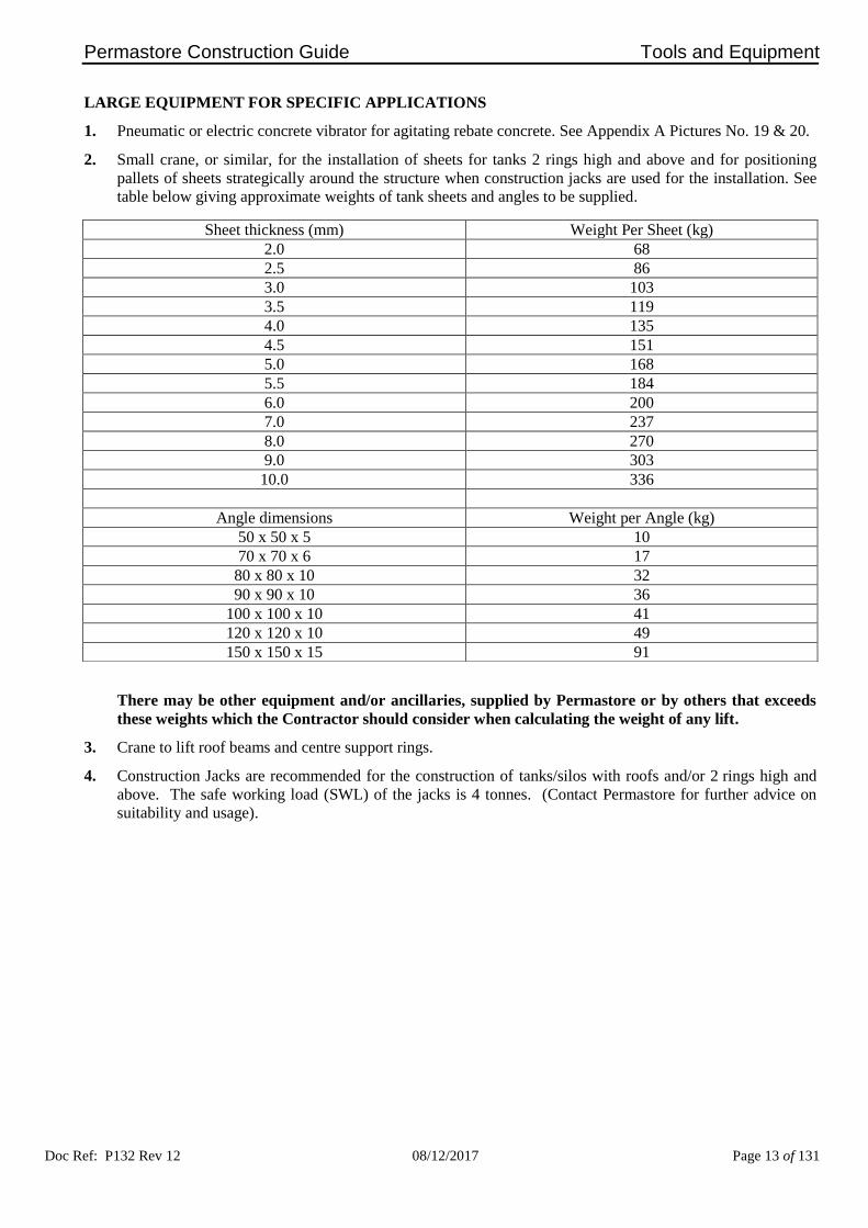
2. Small crane, or similar, for the installation of sheets for tanks 2 rings high and above and for positioning
pallets of sheets strategically around the structure when construction jacks are used for the installation. See
table below giving approximate weights of tank sheets and angles to be supplied.
There may be other equipment and/or ancillaries, supplied by Permastore or by others that exceeds
these weights which the Contractor should consider when calculating the weight of any lift.
3. Crane to lift roof beams and centre support rings.
4. Construction Jacks are recommended for the construction of tanks/silos with roofs and/or 2 rings high and
above. The safe working load (SWL) of the jacks is 4 tonnes. (Contact Permastore for further advice on
suitability and usage).
Sheet thickness (mm) Weight Per Sheet (kg)
2.0 68
2.5 86
3.0 103
3.5 119
4.0 135
4.5 151
5.0 168
5.5 184
6.0 200
7.0 237
8.0 270
9.0 303
10.0 336
Angle dimensions Weight per Angle (kg)
50 x 50 x 5 10
70 x 70 x 6 17
80 x 80 x 10 32
90 x 90 x 10 36
100 x 100 x 10 41
120 x 120 x 10 49
150 x 150 x 15 91

Permastore Construction Guide
Doc Ref: P132 Rev 12 08/12/2017 Page 14 of 131
PART ONE – Section 3
Planning

Permastore Construction Guide Planning
Doc Ref: P132 Rev 12 08/12/2017 Page 15 of 131
PLANNING
All work must be carried out in accordance with all relevant local health and safety regulations. It is the
responsibility of the Contractor undertaking these works to consider each particular installation, its
environment and the specific risks therein prior to commencement of work. The Contractor shall
determine the protective equipment required by personnel and plan the safe system of work that should be
adopted in order for the tasks to be carried out safely.
1. Site Practice
To ensure that all work is carried out to the required standard of quality, observe the following rules:-
a) Tank and silo kits are packed appropriately prior to shipment. It is recommended that they are held in
secure storage prior to delivery to site.
b) Store tank and silo kits off the ground and clear of any surface water. Avoid storing tank and silo kits in
busy areas where they may suffer damage.
c) All sheets are palletised for transportation. Whenever possible, transport the sheets to site on their
original pallets. Use care when lifting sheets off the stack.
d) Store sealants in accordance with the manufacturer’s recommendations.
2. The Distributor/Contractor should ensure the availability of the tools and equipment list in Section 2 of this
guide.
3. The Distributor/Contractor should appoint a suitably qualified construction team and also ensure that all
plant and materials required will be on site when required.
4. Usually a member of the construction team is appointed crew leader who has defined responsibilities
relating to safety, planning, construction and other site specific requirements. The crew leader should:-
a) Liaise with the Distributor/Contractor to ensure the arrival of plant and materials;
b) Liaise with the Customer to discuss the site plan and safe site working with respect to other sub-
Contractors and normal site operations;
c) Be responsible and set a good example to the other members of the crew.
d) The crew leader must also be capable of reading site plans and drawings, and be conversant with all
aspects of erection work.
e) The crew leader should maintain a clean and tidy site, with clear space for people to work in.
ON ARRIVAL AT SITE
1. The Crew Leader Should:-
a) Make contact with the Customer and jointly inspect the site location to ensure that there are no obvious
safety hazards (eg overhead power cables etc.) and that clear access is available for delivery vehicles
and construction equipment. Ensure that facilities are available as appropriate, toilets, washing facility
and rest room. Familiarise and comply with all site regulations.
b) Check the base against the relevant drawings to ensure that it is fit for purpose prior to the
commencement of any construction.
c) If there is any doubt as to the suitability of the site for the PERMASTORE® structure, work must not
commence until the site has been accepted.
d) Ensure that the Distributor/Contractor has provided all the necessary materials. Remember that
materials are not always available at short notice.

Permastore Construction Guide Planning
Doc Ref: P132 Rev 12 08/12/2017 Page 16 of 131
2. The Remaining Crew Members Should:-
a) Make a thorough check of the parts box and sheet pallets against the packing list provided and report
any shortages immediately to the crew leader. The Distributor/Contractor should immediately report
any shortages so as to prevent delays at a later stage of the construction.
b) Do sub-assembly work on ladders and platforms.
3. During Construction
Supervision checks should be made:-
a) Where construction of the tank or silo is on a previously prepared concrete foundation by others, the
centre point and orientation data must be marked by the Customer or his representative.
b) After the base ring is complete and before pouring concrete, the base ring should conform to the
specified levels, concentricity (fit top angle temporarily) and be clamped securely.
c) Following or during construction the internal Glass-Fused-to-Steel or Fusion Bonded Epoxy coating
should be checked using an Elcometer swab tester or similar in the presence of the Customer's
representative to ensure continuity. Part Ten – Section 1 of this guide refers.
4. After Structure Completion
The structure must be inspected by the Distributor/Contractor or his delegated competent representative in
accordance with the specifications detailed herein, ensuring the appropriate serial / identification is firmly
attached to a tank or silo bolt. Make reference to the Permastore Inspection and Maintenance Manual
Document Reference P110, as well as Part Eleven of this guide.


Permastore Construction Guide
Doc Ref: P132 Rev 12 08/12/2017 Page 17 of 131
PART ONE – Section 4
General Construction Information

Permastore Construction Guide General Construction Information
Doc Ref: P132 Rev 12 08/12/2017 Page 18 of 131
GENERAL CONSTRUCTION INFORMATION
1. Care must be taken not to damage coated sheet edges. Sheets must not be placed directly on concrete or other
abrasive surfaces but placed on wooden blocks or similar.
2. The tank/silo sheet surfaces must be clean and dry when primer/sealant is being applied. See item 1 b) under
'Standard Sealants and Primers, Part One – Section 6.
Sealant must always be spread to cover the total area of the overlap to ensure correct sealing. Cleaners,
aktivators and/or primers shall be applied, as required, in accordance with the sealant manufacturer’s
recommendations, observing minimum and maximum flash off times.
3. All sheets are supplied rolled to a nominal diameter. Tank or silo sheets are rolled to a diameter that depends
on the sheet thickness and the structure diameter. Thinner sheets will flex to the required diameter but special
care should be taken when handling. Thicker sheets will flex much less and, subject to normal tolerances
being taken into account and tank radius, may have been rolled to the exact structure diameter.

Permastore Construction Guide General Construction Information
Doc Ref: P132 Rev 12 08/12/2017 Page 19 of 131
Take care that objects are not dropped onto any Glass-Fused-to-Steel or Epoxy coated sheets.
4. Structures are assembled using 12mm or ½ inch bolts within 13.8mm (0.543 inch) holes. It is important that
all vertical joints are fully expanded during construction to prevent movement under full hydraulic load, failure
to do this can cause leaks and deformed vertical seams. See Assembly of Tanks and Silos from the Base Ring
upwards, Part Three – Section 1 for clarification
5. For tanks incorporating double skins, vertical joints must be fully expanded using a tank sheet hydraulic joint
expander assembly. A sheet joint expander kit is available from Permastore.
6. When building structures from the base up it is recommended that assembly of rings of sheets is carried out
clockwise so that each new sheet is assembled inside the previous sheet.
7. Bolts should be tightened to a torque of 65Nm (46ft-lb) except through tapered inserts, which should be
tightened to a torque of 32Nm (23ft-lb).
Failure to conform to this standard may cause damage to the coating of the tank or silo sheets or leaks
in the built structure.
8. It is essential that the correct length bolts are used in the correct place during construction.
Always check fixings charts for the bolt sizes to be used. Please refer to Tank and Silo Fixing Details,
Part One – Section 7.
9. Before inserting the structure bolts, ensure sealant has been applied into and around each bolt hole as a
safeguard against leaks.

Permastore Construction Guide General Construction Information
Doc Ref: P132 Rev 12 08/12/2017 Page 20 of 131
10. It is essential to apply a fillet of sealant around all coated sheet edges, vertical and horizontal, both inside and
outside the structure.
11. At all points where an angle overlaps a vertical joint, rubber tapered inserts (part number 558344, 558345 or
558346) must be used.
12. All ancillary items bolted to tank or silo sheets such as angles and brackets must be fully coated with sealant
on contact surfaces to prevent leakage. Ancillary item surfaces must be clean and dry and, where appropriate,
aktivators or primers should be used.

Permastore Construction Guide General Construction Information
Doc Ref: P132 Rev 12 08/12/2017 Page 21 of 131
13. All levels must always be maintained at ±1.5mm (1/16 inch) over the circumference of the tank.
Wherever possible levels should be checked from within the structure.
14. The circularity on all structures must be to the following standards:-
Diameter Circularity
Up to 13.7m (45ft) ± 6mm (¼ inch)
From 14.5m to 26.5m
(48ft to 87ft) ± 12.5mm (½ inch)
27.3m (90ft) and
above ± 25mm (1 inch)
Refer to Part One – Section 8 for structure diameters.

Permastore Construction Guide General Construction Information
Doc Ref: P132 Rev 12 08/12/2017 Page 22 of 131
15. The vertical joint and corner assembly arrangements for each vertical Series 1400 sheet joint interchanges are
shown below, the individual drawings show the sheet relationship and the general view shows an 'as-built'
typical example when viewed from the exterior of the structure.

Permastore Construction Guide General Construction Information
Doc Ref: P132 Rev 12 08/12/2017 Page 23 of 131
16. Sheet inspection and identification labels, which are placed near a vertical seam overlap joint, should be
removed before applying the primer / sealant.
17. Trade Mark labels shall not be removed.
18. The length of Permastore store-bolts can be determined by the colour of the capped bolt heads:-
The capped bolt head is always placed on the inside of the structure.
Standard Bolts:-
Colour Length
(mm)
Length
(inches)
Black 25 1
Grey 32 1¼
Blue 38 1½
White 44 1¾
Red 51 2
Green 64 2½
Special Bolts:-
Colour Length
(mm)
Length
(inches)
Brown 51 2
Mauve 64 2½
Yellow 76 3
19. If tank or silo sheets require cutting on site the operation must always be carried out using a jig-saw type
cutter. See Appendix A, Picture No. 18.
20. Do not attempt to cut PERMASTORE® sheets with gas cutting equipment or use on other parts in the locality
of the tank or silo sheets, where sparks may contact and adhere to the surface.
21. Do not attempt to cut PERMASTORE® tank or silo sheets with a mechanical grinder. Grinders should not be
used in the locality of PERMASTORE® structures. Sparks may make contact and adhere to the Glass-Fused-
to-Steel or Fusion Bonded Epoxy surface. Protect the sheets with plywood secured to the sheets if other works
using grinders are being carried out in close proximity to the tank or silo being constructed.
Permastore cannot accept any responsibility for any modifications to the structure, including loads, cut-
outs or fitments without prior consultation and advice.


Permastore Construction Guide
Doc Ref: P132 Rev 12 08/12/2017 Page 24 of 131
PART ONE – Section 5
Sheet Identification

Permastore Construction Guide Sheet Identification
Doc Ref: P132 Rev 12 08/12/2017 Page 25 of 131
SHEET IDENTIFICATION
The sheet identification system (ID holes) is visible externally after construction and the ID piercing provides a
clear indication of sheet thickness, steel grade and sheet taper.
1. Material Identification
Three different hole shapes indicate the grade of steel:-
2. Material Thickness Identification
To indicate the sheet thickness the standard horizontal bolt holes are used as datum points.
"Whole numbers" i.e. 2.0mm, 3.0mm, 4.0mm etc. are positioned 40mm to the right of the datum point and the
"half numbers" i.e. 2.5mm, 3.5mm etc. are positioned 40mm to the left of the next datum point. For double
horizontally pierced sheets, (DH, 63.85mm hole spacing) the same cut-out locations are used, irrespective of the
additional store bolt holes.
3. Material Identification Examples
6.0mm sheets and above are all HSLA5 and the material is therefore identified by a 19 x 11 obround as detailed
in item 1.

Permastore Construction Guide Sheet Identification
Doc Ref: P132 Rev 12 08/12/2017 Page 26 of 131
Taper Identification
In order to ensure trouble free sheet to sheet assembly, Series 1400 sheet bolt hole patterns are produced with a
taper to accommodate the horizontal overlap. Dependent on the sheet thickness and tank diameter one of the
following options will be provided. The absence of any notch would signify a straight sheet with no taper.
Notch 1 = Taper Reference 14t
Notch 1 & 2 = Taper Reference 38t
Notch 1, 2 & 3 = Taper Reference 62t
Notch 1, 2, 3 & 4 = Taper Reference 86t


Permastore Construction Guide
Doc Ref: P132 Rev 12 08/12/2017 Page 27 of 131
PART ONE – Section 6
Standard Sealants, Cleaners and Primers

Permastore Construction Guide Sealants and Primers
Doc Ref: P132 Rev 12 08/12/2017 Page 28 of 131
STANDARD SEALANTS, CLEANERS AND PRIMERS
1. Introduction
a) Sealants and Primers may vary in accordance with the process designer’s criteria.
b) Pallets are wrapped after manufacture to ensure that the sheets are clean and dry at the time of
construction. It is essential that sheet surfaces are clean and dry prior to the application of the sealant.
c) When it is necessary to clean Glass-Fused-to-Steel use a product recommended by the sealant
manufacturer as detailed in paragraph 6 or alternatively, Methylethylketone (MEK) or Isopropylalcohol
(IPA).
d) When it is necessary to clean the epoxy and polyester surfaces of FUSION® V1100, use Isopropyl
alcohol (IPA) or a product specific cleaner/activator. FUSION® V1100 should be treated with an
appropriate product recommended by the sealant manufacturer prior to sealant application.
e) Stainless Steel may be cleaned with IPA or a product specific cleaner/activator. Stainless Steel should be
treated with a product recommended by the sealant manufacturer prior to sealant application.
Do not use any solvents or cleaners that might leave a residue or contain turpentine, white spirits,
phenols, organic acids, surfactants or silicones.
Ensure that flash off times are observed.
If in doubt consult sealant manufacturer’s Product Data Sheet.
Always follow the sealant manufacturer's advice on Health and Safety and guidelines for application
and curing times.
Safety Data Sheets are available upon request.
2. Sealants
See Figure 1 for sealant application.
a) Sikaflex® TS Plus is the preferred sealant for sheet joints, edge protection, painted and galvanised
surfaces in direct contact with Glass-Fused-to-Steel panels, Fusion Bonded Epoxy panels, Stainless Steel
panels, perimeter base fillet type seals and minor internal repairs. It is a polyurethane based sealant with
a skin time of approximately 5 hours (at 23°C, 50% RH) which facilitates tank construction. Due to its
high performance specification, Sikaflex® TS plus is usually used for applications with contents in the pH
range 4-11 and temperatures up to a maximum of 55°C. It is not suitable for use with organic solvents.
b) SABA Ecoseal Bio HM is suitable for applications with contents in the pH range 5-14 and temperatures
up to a maximum of 70°C, depending upon contents. It has some organic solvent resistance. It is an MS
polymer based sealant with a skin time of approximately 15 minutes (at 23°C, 50% RH.)
c) SABA Ecoseal AC is suitable for applications with contents in the pH range 1-9 and temperatures up to a
maximum of 70°C, depending upon contents. It has some organic solvent resistance. It is an MS
polymer based sealant with a skin time of approximately 15 minutes (at 23°C, 50% RH.)
d) SABA MB-T is suitable for applications with organic solvents and contents up to a maximum
temperature of 120°C. It is a 2 component polysulphide based sealant with a pot life of 2 hours (at 23°C,
50% RH.)
e) MANUS-BOND 75 AM is suitable for applications with contents in the pH range 4-11 and temperatures
up to a maximum of 70°C, depending upon contents. It has some organic solvent resistance. It is a
polyether based sealant with a maximum skin time of 30 minutes (at 25°C, 50% RH.)
f) PPG PRC Rapidseal® 652 is suitable for use with petrochemical products and contents up to a maximum
temperature of 120°C. It is a 2 component polysulphide based sealant with an application time of 60
minutes (at 23°C.)
3. Hydrophilic base seal.
a) Sikaswell® S2
4. Perimeter bond breaker
a) Sikalastomer® 710 is used in conjunction with base sealant for tanks above 33.2m diameter and 11.2m in
height.

Permastore Construction Guide Sealants and Primers
Doc Ref: P132 Rev 12 08/12/2017 Page 29 of 131
5. Primers
a) Sika® Primer-3N is a concrete primer for use with Sikaflex® TS Plus on perimeter base seals.
b) Sika® Primer-210 is the preferred primer for use with Sikaflex® TS Plus on galvanised surfaces.
c) Sika Primer-206 G+P may be used to give improved adhesion on substrates such as Fusion Bonded
Epoxy or Polyester.
d) SABA Primer 9002 is the preferred primer for use with SABA Ecoseal Bio HM and SABA Ecoseal AC.
e) SABA Primer H17 is the preferred primer for use with SABA MB-T. It is a two component material.
f) PPG PR-148 is the preferred adhesion promoter for use with PPG PRC Rapidseal® 652.
6. Cleaners/activators.
a) Sika® Aktivator-205 is a general cleaner/activator for Sikaflex® TS Plus for use on non-porous surfaces.
7. Permastore Repair Kit Corroless EP
a) Minor repairs to panel surfaces and sheet edges.
Figure 1 Sealant Application


Permastore Construction Guide
Doc Ref: P132 Rev 12 08/12/2017 Page 30 of 131
PART ONE – Section 7
Tank and Silo Fixing Details

Permastore Construction Guide Tank and Silo Fixing Details
Doc Ref: P132 Rev 12 08/12/2017 Page 31 of 131

Permastore Construction Guide Tank and Silo Fixing Details
Doc Ref: P132 Rev 12 08/12/2017 Page 32 of 123
SILO BOLT FIXINGS CHART - STRAIGHT SEAM SHEETS (1400 SERIES) WITH STANDARD BASE
TOP STIFFENER ANGLE TO: (ASSUMING 6mm THICK TSA)
2.0 2.5 3.0 3.5 4.0 4.5 5.0 5.5 6.0 7.0 8.0 9.0 10.0 1 SPLICE TO TSA SPR X 4 ALL SHEETS 1½ 1½ 1½ 1½ 1½ 1½ 1½ 1¾ 1¾ 1¾ 1¾ 2 2 2 SHEET OVERLAP TO TSA SPR X 2 SHSV/SHDV 1¼ 1¼ 1½ 1½ 1½ 1½ 1½ 1¾ 1¾ 1¾ 1¾ 2 2 3 SHEET TO TSA SPR X 17 SHSV/SHDV 1¼ 1¼ 1¼ 1¼ 1¼ 1¼ 1¼ 1½ 1½ 1½ 1½ 1½ 1¾ 4 SPLICE TO TSA SPR X 4 TRV 1½ 1½ 1½ 1½ 1½ 1½ 1½ 1¾ 1¾ 1¾ 1¾ 2 2 5 SHEET OVERLAP TO TSA SPR X 4 TRV 1¼ 1¼ 1½ 1½ 1½ 1½ 1½ 1¾ 1¾ 1¾ 1¾ 2 2 6 SHEET TO TSA SPR X 15 TRV 1¼ 1¼ 1¼ 1¼ 1¼ 1¼ 1¼ 1½ 1½ 1½ 1½ 1½ 1¾ 7 SPLICE TO TSA SPR X 4 QRV 1½ 1½ 1½ 1½ 1½ 1½ 1½ 1¾ 1¾ 1¾ 1¾ 2 2 8 SHEET OVERLAP TO TSA SPR X 5 QRV 1¼ 1¼ 1½ 1½ 1½ 1½ 1½ 1¾ 1¾ 1¾ 1¾ 2 2 9 SHEET TO TSA SPR X 14 QRV 1¼ 1¼ 1¼ 1¼ 1¼ 1¼ 1¼ 1½ 1½ 1½ 1½ 1½ 1¾
VERTICAL SEAM OVERLAP
2.0 to 2.0
2.0 to 2.5
2.5 to 2.5
2.5 to 3.0
3.0 to 3.0
3.0 to 3.5
3.5 to 3.5
3.5 to 4.0
4.0 to 4.0
4.0 to 4.5
4.5 to 4.5
4.5 to 5.0
5.0 to 5.0
5.0 to 5.5
5.5 to 5.5
5.5 to 6.0
6.0 to 6.0
6.0 to 7.0
7.0 to 7.0
7.0 to 8.0
8.0 to 8.0
8.0 to 9.0
9.0 to 9.0
9.0 to
10.0
10.0 to
10.0 14 FULL SHEET SPR X 17 SV 1 1 1 1 1 1 1¼ 1¼ 1¼ 1¼ 1¼ 1¼ 1¼ 1¼ 1½ 1½ 1½ 1½ 1½ 1½ 1¾ 1¾ 1¾ 1¾ 2 15 FULL SHEET SPR X 34 DV 1 1 1 1 1 1 1¼ 1¼ 1¼ 1¼ 1¼ 1¼ 1¼ 1¼ 1½ 1½ 1½ 1½ 1½ 1½ 1¾ 1¾ 1¾ 1¾ 2 16 FULL SHEET SPR X 44 TRV 1 1 1 1 1 1 1¼ 1¼ 1¼ 1¼ 1¼ 1¼ 1¼ 1¼ 1½ 1½ 1½ 1½ 1½ 1½ 1¾ 1¾ 1¾ 1¾ 2 17 FULL SHEET SPR X 68 QRV 1 1 1 1 1 1 1¼ 1¼ 1¼ 1¼ 1¼ 1¼ 1¼ 1¼ 1½ 1½ 1½ 1½ 1½ 1½ 1¾ 1¾ 1¾ 1¾ 2 18 HALF SHEET SPR X 8 SV 1 1 1 1 1 1 1¼ 1¼ 1¼ 1¼ 1¼ 1¼ 1¼ 1¼ 1½ 1½ 1½ 1½ 1½ 1½ 1¾ 1¾ 1¾ 1¾ 2 19 HALF SHEET SPR X 15 DV 1 1 1 1 1 1 1¼ 1¼ 1¼ 1¼ 1¼ 1¼ 1¼ 1¼ 1½ 1½ 1½ 1½ 1½ 1½ 1¾ 1¾ 1¾ 1¾ 2 20 HALF SHEET SPR X 19 TRV 1 1 1 1 1 1 1¼ 1¼ 1¼ 1¼ 1¼ 1¼ 1¼ 1¼ 1½ 1½ 1½ 1½ 1½ 1½ 1¾ 1¾ 1¾ 1¾ 2 21 HALF SHEET SPR X 30 QRV 1 1 1 1 1 1 1¼ 1¼ 1¼ 1¼ 1¼ 1¼ 1¼ 1¼ 1½ 1½ 1½ 1½ 1½ 1½ 1¾ 1¾ 1¾ 1¾ 2 22 STARTER SHEET SPR X 5 TRV 1 1 1 1 1 1 1¼ 1¼ 1¼ 1¼ 1¼ 1¼ 1¼ 1¼ 1½ 1½ 1½ 1½ 1½ 1½ 1¾ 1¾ 1¾ 1¾ 2 23 STARTER SHEET SPR X 7 QRV 1 1 1 1 1 1 1¼ 1¼ 1¼ 1¼ 1¼ 1¼ 1¼ 1¼ 1½ 1½ 1½ 1½ 1½ 1½ 1¾ 1¾ 1¾ 1¾ 2
UPPER SHEET CONFIGURATION
HORIZONTAL OVERLAP
2* = 522500-108 LONG SHANK BOLTS MUST BE USED AT THESE LOCATIONS
26 SV/DV = 1 : TRV = 3 : QRV = 4 X SPR 1 1 1¼ 1¼ 1¼ 1¼ 1½ 1½ 1½ 1½ 1½ 1½ 1½ 1½ 1¾ 1¾ 1¾ 1¾ 2 2 2 2 2* 2* 2* 27 SV/DV = 22 : TRV = 20 : QRV = 19 X SPR 1 1 1 1 1 1 1¼ 1¼ 1¼ 1¼ 1¼ 1¼ 1¼ 1¼ 1½ 1½ 1½ 1½ 1½ 1½ 1¾ 1¾ 1¾ 1¾ 2
UPPER SHEET CONFIGURATION
HORIZONTAL OVERLAP C/W WSA
2* = 522500-108 LONG SHANK BOLTS MUST BE USED AT THESE LOCATIONS
29 SV/DV = 8 : TRV = 10 : QRV = 11 X SPR 1¼ 1¼ 1¼ 1¼ 1¼ 1¼ 1½ 1½ 1½ 1½ 1½ 1½ 1½ 1½ 1¾ 1¾ 1¾ 1¾ 2 2 2 2 2 2 2* 30 SV/DV = 15 : TRV = 13 : QRV = 12 X SPR 1 1 1 1 1 1 1¼ 1¼ 1¼ 1¼ 1¼ 1¼ 1¼ 1¼ 1½ 1½ 1½ 1½ 1½ 1½ 1¾ 1¾ 1¾ 1¾ 2
FOUNDATION ANGLES TO : (ASSUMING 6mm THICK FSA) NOTES: 1. 522400-*** ST.ST CAPPED BOLTS ARE SUPPLIED FOR AREAS WHERE
PERIMITER SEAL IS NORMALLY USED. i.e. BASE LEVEL USE 2 X SPR FOR SRV AND DRV, 4 X SPR FOR TRV AND 6 X SPR FOR QRV.
2. ALL BOLTS HAVE 1 X 511425 NUT AND 1 X 510440 WASHER 3. BOLT DIMENSIONS ARE IMPERIAL, SHEET THICKNESSES ARE METRIC 4. SPR = SHEETS PER RING
STANDARD BASE BOLT FIXINGS
2.0 2.5 3.0 3.5 4.0 4.5 5.0 5.5 6.0 7.0 8.0 9.0 10.0
33
SPR X 1 SHSV/SHDV 1¼ 1¼ 1½ 1½ 1½ 1½ 1½ 1¾ 1¾ 1¾ 1¾ 2 2
34
SPR X 13 SHSV/SHDV 1¼ 1¼ 1¼ 1¼ 1¼ 1¼ 1¼ 1½ 1½ 1½ 1½ 1½ 1¾
35
SPR X 4 TRV 1¼ 1¼ 1½ 1½ 1½ 1½ 1½ 1¾ 1¾ 1¾ 1¾ 2 2
36
SPR X 10 TRV 1¼ 1¼ 1¼ 1¼ 1¼ 1¼ 1¼ 1½ 1½ 1½ 1½ 1½ 1¾
37
SPR X 5 QRV 1¼ 1¼ 1½ 1½ 1½ 1½ 1½ 1¾ 1¾ 1¾ 1¾ 2 2
38
SPR X 9 QRV 1¼ 1¼ 1¼ 1¼ 1¼ 1¼ 1¼ 1½ 1½ 1½ 1½ 1½ 1¾

Permastore Construction Guide Tank and Silo Fixing Details
Doc Ref: P132 Rev 12 08/12/2017 Page 33 of 123
METRIC BOLT FIXINGS CHART - STRAIGHT SEAM SHEETS (1400 SERIES) WITH STANDARD BASE
TOP STIFFENER ANGLE TO: (ASSUMING 6mm THICK TSA)
2.0 2.5 3.0 3.5 4.0 4.5 5.0 5.5 6.0 7.0 8.0 9.0 10.0 1 SPLICE TO TSA SPR X 4 ALL SHEETS 40 40 40 40 40 40 40 40 40 40 40 40 40 2 SHEET OVERLAP TO TSA SPR X 2 SHSV/SHDV 30 30 30 40 40 40 40 40 40 40 40 50 50 3 SHEET TO TSA SPR X 17 SHSV/SHDV 30 30 30 30 30 30 30 30 30 40 40 40 40 4 SPLICE TO TSA SPR X 4 TRV 40 40 40 40 40 40 40 40 40 40 40 40 40 5 SHEET OVERLAP TO TSA SPR X 4 TRV 30 30 30 40 40 40 40 40 40 40 40 50 50 6 SHEET TO TSA SPR X 15 TRV 30 30 30 30 30 30 30 30 30 40 40 40 40 7 SPLICE TO TSA SPR X 4 QRV 40 40 40 40 40 40 40 40 40 40 40 40 40 8 SHEET OVERLAP TO TSA SPR X 5 QRV 30 30 30 40 40 40 40 40 40 40 40 50 50 9 SHEET TO TSA SPR X 14 QRV 30 30 30 30 30 30 30 30 30 40 40 40 40
VERTICAL SEAM OVERLAP
2.0 to 2.0
2.0 to 2.5
2.5 to 2.5
2.5 to 3.0
3.0 to 3.0
3.0 to 3.5
3.5 to 3.5
3.5 to 4.0
4.0 to 4.0
4.0 to 4.5
4.5 to 4.5
4.5 to 5.0
5.0 to 5.0
5.0 to 5.5
5.5 to 5.5
5.5 to 6.0
6.0 to 6.0
6.0 to 7.0
7.0 to 7.0
7.0 to 8.0
8.0 to 8.0
8.0 to 9.0
9.0 to 9.0
9.0 to
10.0
10.0 to
10.0 14 FULL SHEET SPR X 17 SV 30 30 30 30 30 30 30 30 30 30 30 30 30 30 30 30 30 40 40 40 40 40 40 40 40 15 FULL SHEET SPR X 34 DV 30 30 30 30 30 30 30 30 30 30 30 30 30 30 30 30 30 40 40 40 40 40 40 40 40 16 FULL SHEET SPR X 44 TRV 30 30 30 30 30 30 30 30 30 30 30 30 30 30 30 30 30 40 40 40 40 40 40 40 40 17 FULL SHEET SPR X 68 QRV 30 30 30 30 30 30 30 30 30 30 30 30 30 30 30 30 30 40 40 40 40 40 40 40 40 18 HALF SHEET SPR X 8 SV 30 30 30 30 30 30 30 30 30 30 30 30 30 30 30 30 30 40 40 40 40 40 40 40 40 19 HALF SHEET SPR X 15 DV 30 30 30 30 30 30 30 30 30 30 30 30 30 30 30 30 30 40 40 40 40 40 40 40 40 20 HALF SHEET SPR X 19 TRV 30 30 30 30 30 30 30 30 30 30 30 30 30 30 30 30 30 40 40 40 40 40 40 40 40 21 HALF SHEET SPR X 30 QRV 30 30 30 30 30 30 30 30 30 30 30 30 30 30 30 30 30 40 40 40 40 40 40 40 40 22 STARTER SHEET SPR X 5 TRV 30 30 30 30 30 30 30 30 30 30 30 30 30 30 30 30 30 40 40 40 40 40 40 40 40 23 STARTER SHEET SPR X 7 QRV 30 30 30 30 30 30 30 30 30 30 30 30 30 30 30 30 30 40 40 40 40 40 40 40 40
UPPER SHEET CONFIGURATION
HORIZONTAL OVERLAP
2* = 522500-108 LONG SHANK BOLTS MUST BE USED AT THESE LOCATIONS
26 SV/DV = 1 : TRV = 3 : QRV = 4 X SPR 30 30 30 30 30 30 30 30 30 40 40 40 40 40 40 40 40 40 40 40 50 50 50 50 50 27 SV/DV = 22 : TRV = 20 : QRV = 19 X SPR 30 30 30 30 30 30 30 30 30 30 30 30 30 30 30 30 30 40 40 40 40 40 40 40 40
UPPER SHEET CONFIGURATION
HORIZONTAL OVERLAP C/W WSA
2* = 522500-108 LONG SHANK BOLTS MUST BE USED AT THESE LOCATIONS
29 SV/DV = 8 : TRV = 10 : QRV = 11 X SPR 30 30 30 30 30 30 30 30 30 40 40 40 40 40 40 40 40 40 40 40 50 50 50 50 50 30 SV/DV = 15 : TRV = 13 : QRV = 12 X SPR 30 30 30 30 30 30 30 30 30 30 30 30 30 30 30 30 30 40 40 40 40 40 40 40 40
FOUNDATION ANGLES TO : (ASSUMING 6mm THICK FSA) NOTES: 1. STAINLESS STEEL SET SCREWS ARE SUPPLIED AS PER THIS TABLE. 2. ALL BOLTS HAVE 1 X M12 NUT AND 2 X FORM A WASHER 3. BOLT DIMENSIONS AND SHEET THICKNESSES ARE METRIC 4. SPR = SHEETS PER RING
STANDARD BASE BOLT FIXINGS
2.0 2.5 3.0 3.5 4.0 4.5 5.0 5.5 6.0 7.0 8.0 9.0 10.0
33
SPR X 1 SHSV/SHDV 30 30 30 30 30 30 30 30 30 40 40 40 40 34
SPR X 13 SHSV/SHDV 30 30 30 30 30 30 30 30 30 40 40 40 40
35
SPR X 4 TRV 30 30 30 30 30 30 30 30 30 40 40 40 40 36
SPR X 10 TRV 30 30 30 30 30 30 30 30 30 40 40 40 40
37
SPR X 5 QRV 30 30 30 30 30 30 30 30 30 40 40 40 40 38
SPR X 9 QRV 30 30 30 30 30 30 30 30 30 40 40 40 40

Permastore Construction Guide Structure Dimensions
Doc Ref: P132 Rev 12 08/12/2017 Page 34 of 131
PART ONE – Section 8
Structure Dimensions

Permastore Construction Guide Structure Dimensions
Doc Ref: P132 Rev 12 08/12/2017 Page 35 of 131
NOMINAL DIMENSION OF STRUCTURES
Nominal Radius Nominal Radius
Model
Diameter
Reference
Sheets
Per
Ring
Metres Feet and
Inches
Model
Diameter
Reference
Sheets
Per
Ring
Metres Feet and
Inches
11 4 1.708 5' 7¼" 146 52 22.200 72' 10"
14 5 2.135 7' 148 53 22.627 74' 2⅞"
17 6 2.562 8' 4⅞" 151 54 23.054 75' 7⅝"
20 7 2.988 9' 9¾" 154 55 23.481 77' ½"
22 8 3.415 11' 2½" 157 56 23.908 78' 5¼"
25 9 3.842 12' 7¼" 160 57 24.335 79' 10⅛"
28 10 4.269 14' ⅛" 162 58 24.762 81' 2⅞"
31 11 4.696 15' 4⅞" 165 59 25.189 82' 7⅝"
34 12 5.123 16' 9¾" 168 60 25.616 84' ½"
36 13 5.550 18' 2½" 171 61 26.042 85' 5¼"
39 14 5.977 19' 7⅜" 174 62 26.470 86' 10⅛"
42 15 6.404 21' ⅛" 176 63 26.896 88' 3"
45 16 6.831 22' 4⅞" 179 64 27.323 89' 7¾"
48 17 7.258 23' 9¾" 182 65 27.750 91' ½"
50 18 7.685 25' 2½" 185 66 28.177 92' 5⅜"
53 19 8.112 26' 7⅜" 188 67 28.604 93' 10⅛"
56 20 8.359 28' ⅛" 190 68 29.031 95' 3"
59 21 8.965 29' 5" 193 69 29.458 96' 7¾"
62 22 9.392 30' 9¾" 196 70 29.885 98' ⅝"
64 23 9.819 32' 2⅝" 199 71 30.311 99' 5⅜"
67 24 10.246 33' 7⅜" 202 72 30.738 100' 10¼"
70 25 10.673 35' ¼" 204 73 31.166 102' 3"
73 26 11.100 36' 5" 207 74 31.593 103' 7¾"
76 27 11.527 37' 9⅞" 210 75 32.020 105' ⅝"
78 28 11.954 39' 2⅝" 213 76 32.447 106' 5⅜"
81 29 12.380 40' 7⅜" 216 77 32.873 107' 10¼"
84 30 12.808 42' ¼" 219 78 33.300 109' 3"
87 31 13.235 43' 5" 221 79 33.727 110' 7⅞"
90 32 13.662 44' 9⅞" 224 80 34.154 112' ⅝"
92 33 14.089 46' 2⅝" 227 81 34.581 113' 5½"
95 34 14.516 47' 7½" 230 82 35.008 113' 10¼"
98 35 14.942 49' ¼" 233 83 35.436 116' 3¼"
101 36 15.369 50' 5⅛" 236 84 35.863 117' 8"
104 37 15.796 51' 9⅞" 239 85 36.290 119' ¾"
106 38 16.223 53' 2¾" 242 86 36.717 120' 5⅝"
109 39 16.650 54' 7½" 245 87 37.144 121' 10½"
112 40 17.077 56' ⅜" 248 88 37.571 123' 3¼"
115 41 17.504 57' 5⅛" 251 89 37.998 124' 8"
118 42 17.931 58' 10" 254 90 38.425 126' ⅞"
120 43 18.358 60' 2¾" 257 91 38.851 127' 5¾
123 44 18.785 61' 7½ 260 92 39.278 128' 10½"
126 45 19.211 63' ⅜" 262 93 39.705 130' 3¼"
129 46 19.638 64' 5⅛" 265 94 40.132 131' 8"
132 47 20.065 65' 10" 268 95 40.559 133' ⅞"
134 48 20.492 67' 2¾" 271 96 40.986 134' 5¾"
137 49 20.919 68' 7⅝" 274 97 41.413 135' 10½"
140 50 21.346 70' ⅞" 277 98 41.840 137' 3¼"
143 51 21.773 71' 5¼" 280 99 42.267 138' 8⅛"

Permastore Construction Guide
Doc Ref: P132 Rev 12 08/12/2017 Page 36 of 131
PART TWO – Section 1
Typical Foundation Design and Sealing Options

Permastore Construction Guide Foundation Design and Sealing Options
Doc Ref: P132 Rev 12 08/12/2017 Page 37 of 131
TYPICAL FOUNDATION DESIGN AND SEALING OPTIONS
The typical designs shown within this guide are for information only, the selection of the most appropriate
application will be determined in consultation with Permastore in the scope of supply of the tank or silo.
Additional foundation design information is available upon request.
1. Ring Beam and Infill Design
Generally considered to be the least complex design and favoured where the installation team has
responsibility for the base and tank construction.
The ring beam can be installed prior to arrival of the tank kit on site and the foundation bolts positioned whilst
the concrete is still wet, if required. It is important to ensure the ring beam concrete surface is level to within
±10mm over the tank circumference.
The base slab (infill) is generally poured following construction of the starter or base ring. Alternatively it is
poured following completion of the tank shell if the structure is being built using construction jacks.
STRUCTURES UP TO AND INCLUDING 8 RINGS HIGH
STRUCTURES ABOVE 8 RINGS HIGH.

Permastore Construction Guide Foundation Design and Sealing Options
Doc Ref: P132 Rev 12 08/12/2017 Page 38 of 131
2. Rebate Base Design
Utilised mainly where the base design and construction is by a third party. The base of the rebate should be
level within ±5mm across the diameter of the base area.
STRUCTURES UP TO AND INCLUDING 8 RINGS HIGH
STRUCTURES ABOVE 8 RINGS HIGH

Permastore Construction Guide Foundation Design and Sealing Options
Doc Ref: P132 Rev 12 08/12/2017 Page 39 of 131
3. Flat Base Design
Generally as shown below, but requires a very high standard of base concrete construction to achieve an
acceptable level and flatness. The minimum standard is a 200mm wide band of the circumference of the tank
base diameter within ±5mm of the specified level and should not vary more than ±3mm in any 3m length.
It is essential that these levels of workmanship are attained to enable the tank to be correctly constructed and
sealed.
4. Agricultural Slurry Tank Base Design
Identical to Ring Beam and Infill design with the exception that cast-in anchor bolts, supplied by Permastore,
are used in the construction.
TANKS UP TO AND INCLUDING 6 RINGS HIGH

Permastore Construction Guide Foundation Design and Sealing Options
Doc Ref: P132 Rev 12 08/12/2017 Page 40 of 131
BASE PERIMETER SEAL OPTIONS
5. Perimeter Fillet Seal for structures up to and including 32.5m diameter and 11.0m in height.
a) Pour the correct specified concrete to the level indicated on the drawing or level with existing
foundations. Ensure that the concrete completely fills the gap between the ring beam or floor slab and
the base angle.
It is important that a concrete vibrator poker is used to ensure that the concrete fully flows beneath
and around the base angle.
Ensure that the sheets are cleaned of any residual concrete, before the concrete dries on the surface.
b) When the concrete has cured sweep clean the perimeter of the foundations inside the structure to remove
any surface debris.
c) Ensure that the sheet surface immediately above the concrete level inside the structure is clean to ensure
good adhesion for the sealant fillet. See item 1 b) under 'Standard Sealants and Primers' Part 1 – Section
6.
d) Apply appropriate Primer (See Part One – Section 6) to the concrete base only extending approximately
50-60mm (2 inches) inwards from the tank or silo wall.
e) Review the specification on the relevant drawings for placing of the perimeter sealant required and then
apply the sealant.
f) Allow sealant to cure in accordance with manufacturer's guidelines.
Serious damage will result to the tank or silo sheets, if a flame torch is used to dry out the base
concrete prior to installing the perimeter base sealant seal.

Permastore Construction Guide Foundation Design and Sealing Options
Doc Ref: P132 Rev 12 08/12/2017 Page 41 of 131
6. Perimeter Fillet Seal with Bond Breaker for structures above 33.2m diameter and 11.2m in height.
a) Pour the concrete to the level indicated on the drawing or level with existing foundations. Ensure that the
concrete completely fills the gap between the ring beam or floor slab and the base angle.
It is important that a concrete vibrator poker is used to ensure that the concrete fully flows beneath
and around the base angle.
Ensure that the sheets are cleaned of any residual concrete, before the concrete dries on the tank or
silo sheets.
b) When the concrete has cured sweep clean the perimeter of the foundations inside the structure to remove
any surface debris.
c) Clean the tank or silo sheet surface immediately above the concrete level inside the structure to ensure
good adhesion for the sealant fillet. See item 1 b) under 'Standard Sealants and Primers' Part 1 – Section 6.
d) Apply appropriate Primer (See Part One – Section 6) to the concrete base only extending approximately
50-60mm (2 inches) inwards from the tank or silo wall.
e) Apply the perimeter bond breaker as detailed in the relevant drawing and ensure it is touch dry.
f) Review the specification on the relevant drawings for placing of the perimeter sealant required and then
apply the sealant.
g) Allow sealant to cure as manufacturer’s instructions. Site conditions, temperature and humidity can affect
the curing times specified.
Serious damage will result to the tank or silo sheets, if a flame torch is used to dry out the base
concrete prior to installing the perimeter base sealant seal.

Permastore Construction Guide
Doc Ref: P132 Rev 12 08/12/2017 Page 42 of 131
PART TWO – Section 2
Tank and Silo to Base Clamping and Levelling Systems

Permastore Construction Guide Clamp and Levelling Systems
Doc Ref: P132 Rev 12 08/12/2017 Page 43 of 131
CLAMP AND SHIMS
1. Brush clean the top surface of the ring wall. Mark out the tank radius on the concrete surface.
2. Place shims in line with each anchor bolt at the correct radius from the centre point of the tank.
Check the levels of the shims to within 1.5mm (1/16 inch).
3. There must be a minimum gap of 25mm (1 inch) between the foundation angles and foundation concrete
Please note the maximum allowance of shims is 50mm around the circumference of the tank foundation
angles.
4. It is essential that anchor clamps are located directly above a shim pack.
LEVELLING SYSTEM
1. Using a Dumpy level or laser level, check that all the levelling plates are installed to within 1.5mm (1/16
inch), whilst always maintaining a minimum of 25mm (1 inch) gap between the foundation concrete and the
underside of the base angles. Tighten the levelling plates.
Always maintain an even adjustment of the levelling plates.
2. From the centre stake, mark out the foundation angle radius on to the levelling plates. Place the foundation
angles around the tank or silo circumference, on top of the levelling plates. Ensure that when sheets are

Permastore Construction Guide Clamp and Levelling Systems
Doc Ref: P132 Rev 12 08/12/2017 Page 44 of 131
fitted vertical seam joints are adjacent to a levelling plate, with another levelling plate situated mid sheet and
they are all equally spaced.
3. Fit the hold down clamps onto the outer anchor bolt and foundation angle and loosely tighten, whilst
checking that the correct radius is maintained.
THROUGH ANGLE FIXING (EMBEDDED AND FLAT BASE STRUCTURES)
1. The base angle will be supplied pre-punched to identify the location of the anchor bolts. Position of bolt
holes to be used is shown on relevant drawing.
2. For applications where the tank or silo is constructed from the base ring upwards (stack building) the
foundation bolts are installed following completion of the base ring. For applications where the tanks are
constructed using jacks the foundation bolts are installed following completion of the final ring of sheets
(base ring).
3. It is essential that shim packs are located in close proximity to the foundation bolts and PVC isolation
washers are fitted.
ANCHOR
BOLT
SHIMS


Permastore Construction Guide
Doc Ref: P132 Rev 12 08/12/2017 Page 45 of 131
PART THREE – Section 1
Assembly of Tanks and Silos from the Base Ring Upwards –
Stack Building

Permastore Construction Guide Assembly Methods
Doc Ref: P132 Rev 12 08/12/2017 Page 46 of 131
ASSEMBLY OF TANKS AND SILOS FROM THE BASE RING UPWARDS (STACK BUILDING)
THE BASE RING OF SHEETS
1. Refer to Part One – Section 7 for bolt charts and to relevant drawings indicating correct bolt placement and
quantities required.
2. Apply sealant to the inside face of the foundation angles and proceed to fit the foundation sheets ensuring
that angles are fitted with an equal overlap from each vertical joint and tapered inserts are fitted at the
vertical joint positions of the foundation angles. See item 2 under 'Standard Sealants and Primers' Part 1 –
Section 6.
3. Working in a clockwise direction around the circumference, apply sealant to the inside face of the vertical
overlapping sheet seam ensuring all bolt holes are covered.
4. Insert a minimum of 3 bolts, equispaced, into each of the vertical and horizontal seams, checking that
sealant has been applied over each bolt hole before inserting the bolts.
It is essential that top angles are fitted temporarily to maintain the tank shape. Bolt the angles to the
top of the ring of sheets under construction each time a new ring is fitted, without sealant, using 6
bolts equally spaced and tightened to 25Nm (18ft-lb).

Permastore Construction Guide Assembly Methods
Doc Ref: P132 Rev 12 08/12/2017 Page 47 of 131
5. Ensure that the vertical seam is fully expanded by inserting tapered podgers into 2 bolt holes. Whilst the
podgers are held in place, expanding the seam, tighten the inserted bolts to hold the seam in place.
6. Insert the remaining bolts, checking that sealant has been applied over each bolt hole.
7. For tank sheets above 10.0mm thick, fully expand vertical joints using a tank sheet hydraulic joint expander
assembly. A sheet joint expander kit is available to purchase from Permastore.
8. Fit all remaining base sheets.
It is ESSENTIAL that levels and circularity are accurately maintained to avoid problems as the
installation progresses. This is particularly relevant to the fitting of the Top Stiffener Angle.
Diameter Circularity
Up to 13.7m (45ft) ± 6mm (¼ inch)
From 14.5m to 26.5m
(48ft to 87ft) ± 12.5mm (½ inch)
27.5m (90ft) and
above ± 25mm (1 inch)
9. Bolt the angles to the top of the ring of sheets under construction each time a new ring is fitted, without
sealant, using 6 bolts equally spaced and tightened to 25Nm (18ft-lb).

Permastore Construction Guide Assembly Methods
Doc Ref: P132 Rev 12 08/12/2017 Page 48 of 131
10. After the vertical joints are fully expanded fit the two bolts left out for this operation and tighten to correct
torque.
Check the circularity of the structure is within the required tolerances.
11. Tighten all bolts to 65Nm (46ft-lb) torque with the exception of bolts through tapered inserts, which should
be tightened to 32Nm (23ft-lb) only.
12. Remove the temporarily fitted top stiffener angles.
Using a pointing tool, point off creating a fillet on the vertical seam sealant. See diagram, below left, for
details of fillet sizes.
Note that overpointing is not required for stainless steel tanks. The excess sealant, on sheet edges
only, should be tooled as shown in the diagram, below right.

Permastore Construction Guide Assembly Methods
Doc Ref: P132 Rev 12 08/12/2017 Page 49 of 131
INTERMEDIATE RINGS
1. Refer to Part One – Section 7 for bolt charts and to relevant drawings indicating correct bolt placement and
quantities required.
2. Build the second ring of sheets using suitable lifting equipment. Refer to tank sheet weight chart in Part 1 –
Section 2.
3. Refer to relevant drawing to see whether wind stiffeners are specified. Mark all structure holes for the wind
stiffener clip angles or web truss stiffener sections with chalk before assembling the ring of sheets. As the
sheets are constructed fit the clip angles or web truss stiffener sections at the same time as the structure bolts
are installed.
It is ESSENTIAL that top angles are fitted temporarily to maintain the tank shape. Bolt the angles to
the top of the ring of sheets under construction each time a new ring is fitted, without sealant, using 6
bolts equally spaced and tightened to 25Nm (18ft-lb).
4. Fully expand vertical joints and check circularity.
5. For tank sheets above 10.0mm thick, fully expand vertical joints using a tank sheet hydraulic joint expander
assembly. A sheet joint expander kit is available to Purchase from Permastore.
6. Tighten from the centre of each sheet to either corner on the horizontal seams; tighten the vertical seam from
the corner joint to the top ensuring that the seam is expanded.
If possible, do not start a new ring of sheets late in the day if only a small number of sheets will be
completed. Where it is not possible to complete a full ring of sheets by the end of the day, secure each
end of the unfinished ring with ropes to prevent any possible overnight wind damage.
7. Before tightening a partially completed ring, ensure the end sheets are truly vertical and supported/braced
until the build resumes as damage may result to tank sheets or coating if not supported.
8. Apply sealant fillets to cover sheet edges on vertical and horizontal joints, both inside and outside the tank.
Note that overpointing is not required for stainless steel tanks.
9. Remove the temporarily fitted top stiffener angle.

Permastore Construction Guide Assembly Methods
Doc Ref: P132 Rev 12 08/12/2017 Page 50 of 131
10. All bolt heads are to have a sealant squeeze out and the 4 corner joints should be completely covered with
sealant.
11. Using a pointing tool, fillet off the vertical and horizontal seam sealant as shown below.

Permastore Construction Guide Assembly Methods
Doc Ref: P132 Rev 12 08/12/2017 Page 51 of 131
Note that overpointing is not required for stainless steel tanks. The excess sealant, on sheet edges only,
should be tooled as shown below.
FINAL TOP RING AND TOP ANGLE ARRANGEMENT
1. Top stiffener angles are generally required on all tanks and silos. Some roof designs do not require the
fitment of top angles. See relevant drawings for reference.
2. When building the final ring of sheets of an open topped tank, the top stiffener angles must be fitted
internally and the top angle splice angle (joiner) fitted externally.
3. For tanks that are to be fitted with a roof, the top angle stiffener angles are mounted externally.
4. The top stiffener angles should be fitted so that the joint occurs symmetrically in the middle of a sheet.
5. Ensure that tapered inserts are used at each vertical joint between the tank sheet and the top stiffener angle.
Please note that, where tapered inserts are used, the fixings should only be torqued to 32Nm (23ft-lb)
maximum.
6. Apply sealant fillets to cover sheet edges on vertical and horizontal joints, both inside and outside the tank,
as detailed previously for intermediate rings.
Permastore Construction Guide Assembly Methods
Doc Ref: P132 Rev 12 08/12/2017 Page 52 of 131
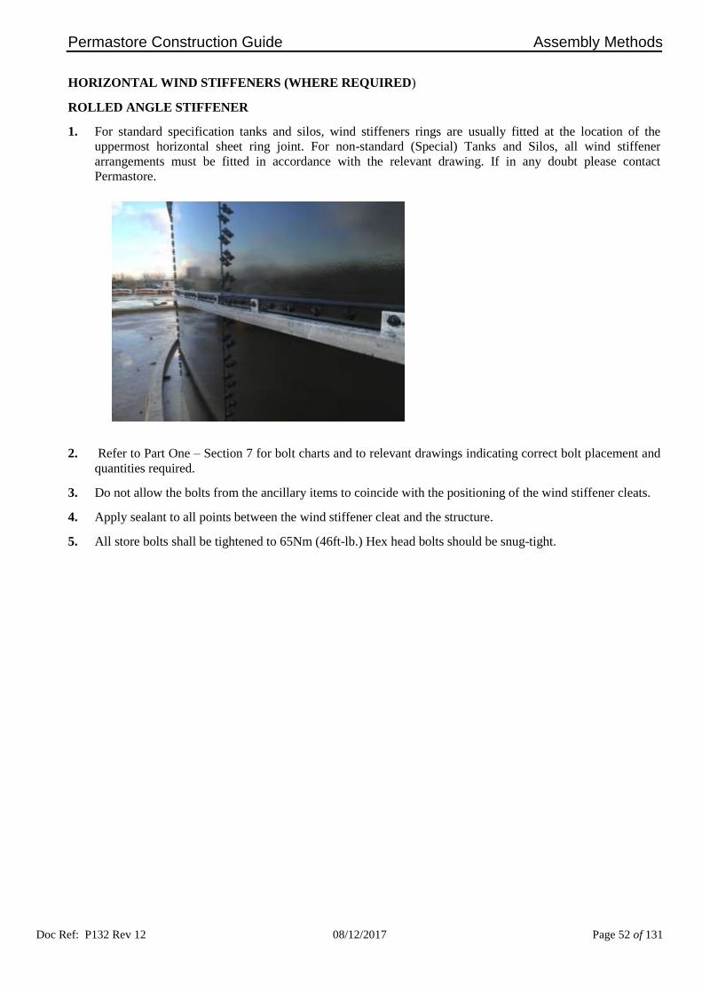
HORIZONTAL WIND STIFFENERS (WHERE REQUIRED)
ROLLED ANGLE STIFFENER
1. For standard specification tanks and silos, wind stiffeners rings are usually fitted at the location of the
uppermost horizontal sheet ring joint. For non-standard (Special) Tanks and Silos, all wind stiffener
arrangements must be fitted in accordance with the relevant drawing. If in any doubt please contact
Permastore.
2. Refer to Part One – Section 7 for bolt charts and to relevant drawings indicating correct bolt placement and
quantities required.
3. Do not allow the bolts from the ancillary items to coincide with the positioning of the wind stiffener cleats.
4. Apply sealant to all points between the wind stiffener cleat and the structure.
5. All store bolts shall be tightened to 65Nm (46ft-lb.) Hex head bolts should be snug-tight.

Permastore Construction Guide Assembly Methods
Doc Ref: P132 Rev 12 08/12/2017 Page 53 of 131
WEB TRUSS STIFFENER
1. For standard specification tanks using a web truss stiffener, the web truss stiffener arrangement is usually
fitted at the location of the uppermost horizontal tank sheet joint. For non-standard (special) tanks and silos,
all web truss stiffener arrangements must be fitted in accordance with the relevant drawing.
2. Refer to Part One – Section 7 for bolt charts and to relevant drawings indicating correct bolt placement and
quantities required.
3. Apply sealant to all points between the web truss stiffener and the structure.
4. Assemble the full diameter of web stiffeners before tightening the fixings. All store bolts shall be tightened
to 65Nm (46ft-lb.) Hex head bolts should be snug-tight.


Permastore Construction Guide
Doc Ref: P132 Rev 12 08/12/2017 Page 54 of 131
PART FOUR – Section 1
Assembly of Tanks and Silos using Construction Jacks

Permastore Construction Guide Assembly Methods
Doc Ref: P132 Rev 12 08/12/2017 Page 55 of 131
ASSEMBLY OF TANKS AND SILOS USING CONSTRUCTION JACKS
1. Important Information
a) Permastore construction jacks are intended only for building PERMASTORE® structures.
b) The construction jacks must only be operated by trained and competent personnel.
c) The jacks must not be used when wind speeds exceed 25mph (40km/hr, force 6 Beaufort). If the wind
speed approaches this figure the structure should be lowered and anchored down to the base. Special care
is needed when gusting winds can exceed this figure.
d) It is considered good practice to lower and anchor the structure any time the structure is left unattended
and every evening in case of overnight winds.
Ensure that anchors are removed prior to jacking.
e) An electrically driven motor assembly drives the jack units via proprietary Power Take-Off (PTO) drive
shafts.
f) Standard operation is for one jack per vertical seam of the structure. For certain applications slave
gearboxes are available to reduce the requirement for standard construction jacks (see “Jack System
Usage Chart” on page 61). Additional motor assemblies are required for special or large structures. (See
“Additional Jack Motor Usage Chart” on page 62)
g) It is recommended that jacks be used on both seams adjacent to platforms, heavy ancillaries or other
point loads such as geodesic dome roof feet.
h) Before setting up the jacks it is essential to ensure that they stand on a firm, level foundation. The jack
bases must be level to prevent overloading of individual jacks and to ensure that the structural load is
evenly distributed across all of the jacks.
i) The jacks must be positioned vertically, fixed to the concrete base using the foundation bolts provided or
clamped to the bottom sheet/angle and supported by centre and side stays. Centre and side stays must be
utilised on every installation. Special length top stays are provided for use with Slave Gearboxes.
j) The jack spacer plate must be used between the carriage and structure sheet.

Permastore Construction Guide Assembly Methods
Doc Ref: P132 Rev 12 08/12/2017 Page 56 of 131
k) Ensure that electricity supply cables cannot be accidentally damaged or cut. Where appropriate, they
should be covered. The use of armoured cable is recommended.
l) Jacks are generally used to construct tanks and silos which are 3 rings high or more. They are also
regularly used to construct structures with roofs or starter rings.
m) Construction jacks must be regularly maintained and load tested.
CONSTRUCTION JACK MAINTENANCE
1. Before Commencement of Work
a) Check splines on gearbox and PTO shafts for wear or damage and ensure that locking pins are free and
oiled. Grease splines on both and ensure PTO shaft guards are fitted correctly.
b) Examine motor couplings and drive shaft splines for wear and check motor/gearbox alignment.
c) Check all turnbuckle threads are free and oiled and stays are in good condition.
d) Examine pin bar carrier assembly for damage or wear and oil jack drive screw.
e) Report any damage of jacks to the Distributor/Contractor.
2. Daily Checks
a) Check pin bar carrier assemblies for damage and security.
b) Check jack retaining clamp for tightness.
c) Examine jack support stays and pins and check jacks are vertical with a level.
d) Make sure that pin bar bolts and nuts are always in good condition. Any replacement bolts must be to the
correct grade (minimum – Grade 8.8) and shank length.
3. Weekly Checks
a) Grease rollers on rear of jack carrier assembly.
b) Grease PTO shaft universal joints.
c) Oil jack drive screws.
Ensure that all jacking equipment is kept clean and in a serviceable condition during the construction
period.
Check that the jacks have not exceeded their maximum travel.
After construction is complete, fully examine all parts for wear and lubricate before packing away.
Report any issues with jacks to Distributor/Contractor/jack owner.

Permastore Construction Guide Assembly Methods
Doc Ref: P132 Rev 12 08/12/2017 Page 57 of 131
EQUIPMENT DESCRIPTION
1. Jacks
a) The jacks have the gearbox and transmission shafts located at the bottom of the jack body and the drive
motor is an independent unit which is floor mounted between two jacks. The jacks are tested for a safe
working load of 4000 kg (8,800 lbs).
b) Storm tags, which are supplied with every jack, shall be utilised to secure the pin bar.
2. Slave Gearboxes
a) A feature of the Permastore jack system is the opportunity to utilise 'slave gearboxes' for a specified
range of applications. Slave gearboxes are low cost units that allow safe construction utilising a reduced
number of jack legs.
b) Special length top stays are provided for use with slave gearboxes to ensure positive location of the
assembled equipment. Centre stays and top stays MUST be utilised on EVERY installation.
c) A recommended usage chart for slave gearboxes and jacks is included for reference (see page 61).

Permastore Construction Guide Assembly Methods
Doc Ref: P132 Rev 12 08/12/2017 Page 58 of 131
SETTING UP FOR JACK CONSTRUCTION
1. Preparation
a) When the centre of the tank has been established, the internal diameter of the tank should be marked out
on the base.
b) Set up base angle, level and check concentricity.
c) Identify the starting point around the circumference. (0°)
d) Place jacks onto the inside of the circumference line. The jack base must be offset by 103mm at each
intended seam position. Note that the jack column will be 140mm from the intended sheet position.
e) Set the pin bar carrier approximately 500mm above the concrete base. Level all the pin bars to within
1mm using a dumpy level or similar. Place the measuring staff into the slot of each pin bar carrier and
drive the jack up or down to achieve the correct level.
f) Use shims if necessary to ensure that the jacks are set plumb vertical to prevent stress during lifting and
possible gearbox damage due to over-run.
g) Fit support struts, use shims to ensure that jacks are vertical and clamp down with foundation bolts
through the base plates or use clamps.
h) Re-check concentricity and clamp down base angles.
i) Assemble top row of sheets onto base angle. Apply sealant to vertical seams only; locate sheet onto base
angle with 4 bolts per sheet. The bolts being fitted in the sheets and bottom angles are only whilst the
jacks are being aligned and must be removed before the jacks are operated. Expand sheets and tighten
vertical bolts to 65Nm (46ft-lb).
j) Assemble the top stiffener angle onto the top row of sheets ensuring tapered inserts are fitted at the
vertical joint positions and splice angles are symmetrically located.

Permastore Construction Guide Assembly Methods
Doc Ref: P132 Rev 12 08/12/2017 Page 59 of 131
k) Install the jack motor(s) and connect the power take off drive shafts and cover guard.
l) Fit PTO shaft guards over the universal joint connections.

Permastore Construction Guide Assembly Methods
Doc Ref: P132 Rev 12 08/12/2017 Page 60 of 131
OPERATION OF JACKS
a) Jack bolts must be of the correct size and strength.
b) Ensure that the jacks are in the low position before connecting to the sheets and ensure that a spacer is
located between the pin bar and the sheet.
c) In all cases a jack bolt (Part No. 540342) must be fitted to every accessible hole in the pin bar. A
minimum of 3 jack bolts must always be utilised.
d) Loosely tighten the jack bolts and raise the structure until weight is being taken on the jacks. Ensure that
the jack bolts are located in the pin bar and tighten.
e) Ensure that the 4 temporarily fitted bolts in the bottom angle / sheet have been removed. Raise the top
ring of sheets to the correct height for installation of the next row of sheets or roof.
Isolate drive motor and remove drive shafts before commencement of placing the second and each
subsequent ring of tank or silo sheets.
When raising the jacks they must not be run up to the end stops. The pin bar carrier must not
travel beyond the safe working area. This will result in damage to the unit and could result in
failure of the equipment.
f) Apply sealant and hang the second row of sheets in an anti-clockwise direction. Leave out the bolts at
the position the jacks will locate on the next lift.
g) Complete a full ring of sheets and fully expand the vertical seams before tightening.
h) Fit wind stiffener assemblies where applicable as full rings are completed.
i) Loosely pull in any gaps in sheet faces, tighten from centre to both corners on the horizontal seam and
tighten the vertical seam from the corner down to the bottom ensuring that the joint is fully expanded.
j) When the ring of sheets is complete lower the structure onto supports until the weight is taken off the
jacks. Remove the jack bolts and spacer bars and lower the jacks to locate on the next sheet. Check that
pin bar carriers do not jam whilst lowering.
When lowering the jacks they must not be run up to the end stops. The pin bar carrier must not
travel beyond the safe working area. This will result in damage to the unit and if persistently
abused this could result in failure of the equipment.
k) Repeat the procedure until the structure is complete.

Permastore Construction Guide Assembly Methods
Doc Ref: P132 Rev 12 08/12/2017 Page 61 of 131
JACK SLAVE SYSTEM USAGE CHART (For guidance only)
Each jack leg has a Safe Working Load (SWL) of 4000 kg (8,800 lbs). For small diameter standard structures
use a jack leg on every vertical seam. For other standard structures up to and including 5 rings high use a
combination of jack legs and slave gearboxes as recommended within the usage chart. Slave gearboxes are
suitable only for structure diameters included within the chart.
For structure diameters outside the scope of this chart including structures with roofs and any structure in excess
of 5 rings high the use of slaves must be assessed on a case by case basis.
Sheets Per Ring
(SPR)
Model Diameter
(ft)
Jack Legs
(No of units)
Slave Gearbox
(No of units)
6 17 6 0 7 20 7 0 8 22 8 0 9 25 9 0
10 28 10 0 11 31 11 0 12 34 9 3 13 36 9 4 14 39 10 4 15 42 10 5 16 45 10 6 17 48 10 7 18 50 10 8 19 53 10 9 20 56 11 9 21 59 11 10 22 62 12 10 23 64 12 11 24 67 13 11 25 70 13 12 26 73 14 12 27 76 14 13 28 78 15 13 29 81 15 14 30 84 16 14 31 87 16 15 32 90 17 15 33 92 17 16 34 95 18 16 35 98 18 17 36 101 19 17 37 104 19 18 38 106 20 18 39 109 20 19 40 112 21 19 41 115 21 20 42 118 22 20 43 120 22 21 44 123 23 21 45 126 23 22 46 129 24 22 47 132 24 23 48 134 25 23 49 137 25 24 50 140 26 24 51 143 26 25 52 146 27 25

Permastore Construction Guide Assembly Methods
Doc Ref: P132 Rev 12 08/12/2017 Page 62 of 131
ADDITIONAL JACK MOTOR USAGE CHART

Permastore Construction Guide
Doc Ref: P132 Rev 12 08/12/2017 Page 63 of 131
PART FOUR – Section 2
Assembly of Tanks and Silos Using Construction Jacks and a Starter Ring

Permastore Construction Guide Assembly Methods
Doc Ref: P132 Rev 12 08/12/2017 Page 64 of 131
SETTING UP FOR TANK OR SILO CONSTRUCTION USING JACKS AND A STARTER RING
Standard base structures may incorporate a starter ring located onto the base angle. Starter rings are generally
used where a tank or silo may be extended at some future date. They are also used to progress installation of the
base foundation and can be supplied in advance of the main tank or silo kit.
1. Locate jack support pin bar at starter ring vertical seam. Space out with washers to allow for thickness of
base sheet.
2. Set up construction jacks as standard procedure.
3. Secure jacks by drilling and rawl bolting through jack base plate into concrete or use clamps.
4. Fit structure support brackets (Part No. 523355) to starter ring.
5. Hang top row of sheets onto jack carriage plates using sealant. Fit all bolts, fully expand seams, check
circularity and tighten bolts to 65Nm (46ft-lb) torque.
6. Continue installation as described in Part Four – Section 1.

Permastore Construction Guide
Doc Ref: P132 Rev 12 08/12/2017 Page 65 of 131
PART FOUR – Section 3
Assembly of Double Skin Tank Sheets

Permastore Construction Guide Assembly Methods
Doc Ref: P132 Rev 12 08/12/2017 Page 66 of 131
ASSEMBLY OF DOUBLE SKIN TANK SHEETS
1. The installation of double skin sheets is a complex procedure. Seek advice from a skilled installation
Engineer for the first installation..
2. Refer to Construction Guide Part Three – Section 1 for general tank construction guidance.
3. Refer to relevant drawings for bolt charts for the particular structure, indicating correct bolt placement,
quantities required and assembly.
4. Note that transition sheets, with single row horizontal seams at the top and double row horizontal seams at
the bottom are required to connect to the double skin assemblies. See diagram on page 68.
5. Ensure double skin sheet assembly rig is available and ready prior to construction. Drawings for the
construction of the assembly jig (540350) can be provided, or one can be purchased from Permastore.
6. Lift the inner double skin sheet onto the assembly rig ensuring the sheet is positioned as shown below.
7. Apply sealant to the vertical and horizontal bolt seams and to the outer surface of the inner sheet.

Permastore Construction Guide Assembly Methods
Doc Ref: P132 Rev 12 08/12/2017 Page 67 of 131
8. Lift the double skin outer sheet onto the inner sheet ensuring the holes are aligned as shown in the view
below. Bolt the inner and outer sheet together using the 8-off bolt holes in the centre of the sheet.
9. Lift the assembled sheets into position for the tank shell construction and apply sealant to the vertical and
horizontal bolt seams of the outer double skin sheet.
DRAWING OF ASSEMBLED INNER AND OUTER DOUBLE SKINNED SHEETS ON ASSEMBLY RIG.
Outer double skin tank sheet
Inner double skin tank sheet
Assembly rig

Permastore Construction Guide Assembly Methods
Doc Ref: P132 Rev 12 08/12/2017 Page 68 of 131
9. Fully expand vertical joints using the double skin tank sheet hydraulic joint expander assembly. A sheet
joint expander kit is available to purchase from Permastore.
10. The vertical joint and corner assembly arrangements for double skin and quad row vertical series 1400 sheet
joint interchanges are shown below as viewed from the exterior of the structure.

Permastore Construction Guide
Doc Ref: P132 Rev 12 08/12/2017 Page 69 of 131
PART FIVE – Section 1
Annular Tanks

Permastore Construction Guide Annular Tank Construction
Doc Ref: P132 Rev 12 08/12/2017 Page 70 of 131
ANNULAR TANKS
All work must be carried out in accordance with all relevant local health and safety regulations. It is the
responsibility of the Contractor undertaking these works to consider each particular installation, its
environment and the specific risks therein prior to commencement of work. The Contractor shall
determine the protective equipment required by personnel and to plan the safe system of work that should
be adopted in order for the tasks to be carried out safely.
Annular tank systems are generally used for continuous process applications. They provide a cost-effective
solution where floor space is at a premium. The basic concept is two circular tanks, usually of equal height, one
inside the other.
1. When constructing an annular tank system, first mark out on the foundation both the inner and outer tank
internal diameters. Also mark a line from the centre which crosses the internal and external marked
diameters for each of the baffle walls.
Before commencing construction work check all the relevant drawings for layout configurations of
tanks, especially if they incorporate launders, baffle walls or revolving bridges. It is important to
ensure the correct orientation and fitment of all constituent parts.
2. Refer to Part Two – Section 2 for details of clamping and levelling systems.
3. Construct the inner tank in accordance with the instructions specified in Part Three and/or Part Four of this
guide. Ensure the baffle wall fixing holes are in line with the marked positions. Fit external stiffener
angles.
4. All exposed store bolts and nuts on the exterior of the inner tank must be protected using the screw on
plastic nut caps provided.
5. Construct the outer tank around the inner tank taking care to ensure that the baffle wall fixing positions are
in alignment and the datum levels are consistent with the inner tank.

Permastore Construction Guide
Doc Ref: P132 Rev 12 08/12/2017 Page 71 of 131
PART FIVE – Section 2
Backfilled Tanks

Permastore Construction Guide Backfilled Tank Construction
Doc Ref: P132 Rev 12 08/12/2017 Page 72 of 131
BACKFILLED TANKS
All work must be carried out in accordance with all relevant local health and safety regulations. It is the
responsibility of the Contractor undertaking these works to consider each particular installation, its
environment and the specific risks therein prior to commencement of work. The Contractor shall determine
the protective equipment required by personnel and to plan the safe system of work that should be adopted
in order for the tasks to be carried out safely.
Every year people are killed or seriously injured by collapses and falling materials while working in
excavations. They are at risk from excavations collapsing and burying or injuring people working in them;
material falling from the sides into any excavation; and people or plant falling into excavations.
Before digging any trench pit, tunnel, or other excavations, decide what temporary support will be required
and plan the precautions to be taken. In granular soils, the angle of slope should be less than the natural
angle of repose of the material being excavated. In wet ground a considerably flatter slope will be required.
A competent person who fully understands the dangers and necessary precautions should inspect the
excavation at the start of each shift. Excavations should also be inspected after any event that may have
affected their strength or stability, or after a fall of rock or earth.
Backfilled tanks are designed to be constructed either wholly or partially below ground level.
1. Check all relevant drawings for layout configurations. It is important to ensure the correct orientation and
fitment of all constituent parts.
2. The tank should be constructed in accordance with the instructions specified in Part Three and/or Part Four of
this guide.
3. During construction it is essential that all the stiffener bands are positioned as shown on the relevant drawing
and all exposed store bolts and nuts on the exterior of the tank must be protected using the plastic screw on
nut caps provided.
4. Before the backfill material is laid the tank must be successfully hydrostatically tested to ensure complete
expansion is achieved and as a check on all joints. The water level inside the tank must be maintained during
backfilling to prevent possible load damage.
5. The backfill should be placed in layers 300mm (12 inches) deep. Each layer must be fully circumferential.
Take care if excavated earth is being re-used to backfill the tank, this may contain larger stones or boulders
which may damage the tank. Sand or pea gravel are the preferred backfill materials but if local earth is to be
used, then hardboard sheets should be used to prevent damage to the tank surface.
6. If the backfill material is to be compacted the density of the compacted material should not be greater than the
surrounding conditions. Ensure that machinery used for compaction does not damage the tank walls.
7. Unless the tank is specifically designed for such loads all heavy vehicles or equipment should not be allowed
close to the tank wall. The limit for heavy traffic is defined by a cone drawn at angle of 45° from the tank
base. Where it is essential that heavy traffic passes close to the tank or parks close to the tank for process
purposes, the tank should be backfilled locally with concrete.
8. Where tanks are designed to be backfilled with a fully drained material a positive drainage system should be
provided.

Permastore Construction Guide Backfilled Tank Construction
Doc Ref: P132 Rev 12 08/12/2017 Page 73 of 131
RECEPTION PITS
All work must be carried out in accordance with all relevant local health and safety regulations. It is the
responsibility of the Contractor undertaking these works to consider each particular installation, its
environment and the specific risks therein prior to commencement of work. The Contractor shall determine
the protective equipment required by personnel and to plan the safe system of work that should be adopted
in order for the tasks to be carried out safely.
Every year people are killed or seriously injured by collapses and falling materials while working in
excavations. They are at risk from excavations collapsing and burying or injuring people working in them;
material falling from the sides into any excavation; and people or plant falling into excavations.
Before digging any trench pit, tunnel, or other excavations, decide what temporary support will be required
and plan the precautions to be taken. In granular soils, the angle of slope should be less than the natural
angle of repose of the material being excavated. In wet ground a considerably flatter slope will be required.
A competent person who fully understands the dangers and necessary precautions should inspect the
excavation at the start of each shift. Excavations should also be inspected after any event that may have
affected their strength or stability, or after a fall of rock or earth.
Reception pits are available in a range of sizes up to a maximum 6m (20ft) diameter, usually 1½ rings deep. They
are mainly utilised in agricultural applications as gravity fed collection tanks.
For excavation dimensions refer to the approved reception pit drawings (supplied separately).
1. Excavate the Pit Area
a) Mark out the perimeter.
b) Determine the total depth and diameter of the pit excavation required and proceed with the excavation,
allowing an additional 600mm (24 inches) on the diameter. Should there be any risk of soil collapse the
excavation area may have to be increased accordingly.
DANGER Under no circumstances should anyone get into the excavation at this stage.
2. Assemble the Pit
a) The pit should be assembled, above ground, on a suitable level and firm foundation, i.e. on an area of
concrete adjacent to the excavated site.
b) Apply sealant to one vertical and one horizontal seam only, ensuring the bolt holes are covered.
c) Start by bolting just the top full ring of sheets together working in a clockwise direction.

Permastore Construction Guide Backfilled Tank Construction
Doc Ref: P132 Rev 12 08/12/2017 Page 74 of 131
d) Fit the top stiffener angles to the ring of sheets using tapered inserts (see Part Three – Section 1) at sheet
overlap points.
e) Fit anchor rods at regular spacing as shown on the approved pit drawing.
f) Temporarily fit the foundation angles to the pit without sealant. Use 4 equally spaced bolts per angle and
tighten to 32Nm (23ft-lb).
g) Tighten all sheet bolts to 65Nm (46ft-lb).
h) The assembled top ring can now be lifted using suitable lifting equipment fixed at 4 equally spaced points
around the pit top. While the pit is suspended, remove the foundation angles and fit the lower ring of
sheets. Fit the foundation angles with sealant, using tapered inserts at the sheet overlap points.
i) Tighten all bolts to the correct torque.
j) Fillet all sheet edges both inside the pit and outside.
An appropriate risk assessment should be carried out prior to any personnel entering a pit and a method
statement prepared. Only suitably trained and skilled crew members should undertake such works.
k) The assembled pit can now be lowered into the excavation and should be suspended clear of the base.
l) Concrete blocks should be placed in position under the foundation angle ensuring they are on a level and
firm footing.
m) Check that the pipe opening is set to the centre line of the main tank and lower the pit onto the concrete
blocks.
n) Check levels and shim until the pit is level to ±1.5mm (1/16 inch) with the shims provided and the top of
the pit is to the required finished height (allowance for pit top or grid to be included).

Permastore Construction Guide Backfilled Tank Construction
Doc Ref: P132 Rev 12 08/12/2017 Page 75 of 131
o) Place the reinforcing mesh in the base area, with reference to relevant drawings, ensuring correct concrete
cover by supporting the mesh with chairs/stools and then pour the concrete into the pit centre. Ensure that
the concrete flows out underneath the foundation angles by using a concrete vibrator. Ensure that levels
inside and outside the pit are correct by referring to the client’s approved pit drawing.
p) Compacted granular fill may be used in the pit excavation to within 100mm (4 inches) of the foundation
angles, unless the distance between the edge of the reception pit and the main tank is less than 2.5m (8ft
3in)., If the distance between the edge of the reception pit and the main tank is more than 2.5m (8ft 3in) it
is advisable to backfill with concrete that half of the pit excavation which is nearest to the main tank.
Determine the amount of compacted granular fill required, taking into account that all inlet pipes and
anchor rods around the top of the pit are to be encased in mass concrete. Refer to the client’s approved
reception pit drawings.
q) When the concrete has cured sufficiently, after a minimum of 3 days, apply a surface primer to the concrete
base only and wait for it to become tack free, then seal inside the pit with a fillet of sealant between the
concrete and tank sheet.
Serious damage will result to the tank sheets if a flame torch is used to dry out base concrete to install
the sealant seal.


Permastore Construction Guide
Doc Ref: P132 Rev 12 08/12/2017 Page 76 of 131
PART SIX – Section 1
Roof Construction Introduction

Permastore Construction Guide Roof Construction
Doc Ref: P132 Rev 12 08/12/2017 Page 77 of 131
INTRODUCTION
All work must be carried out in accordance with all relevant local health and safety regulations. It is the
responsibility of the Contractor undertaking these works to consider each particular installation, its
environment and the specific risks therein prior to commencement of work. The Contractor shall determine
the protective equipment required by personnel and to plan the safe system of work that should be adopted
in order for the tasks to be carried out safely.
Work at height is the biggest single cause of fatal and serious injury in the construction industry. Avoid
work at height where it reasonably practicable to do so, e.g. by assembly at low level. Only authorised
persons/contractors adequately supervised, correctly equipped and trained in all aspects of the risks
involved and the equipment to be used should be employed to carry out this work. An appropriate risk
assessment and method statement must be in place prior to commencement of works, which should include
consideration of fragile roofs and/or roof lights.
1. As a general rule all roofs should be constructed at low level.
2. However, dependent upon the type of roof being installed, site and environmental conditions and other
project-specific factors, roofs may be constructed at other stages of the installation process.

Permastore Construction Guide
Doc Ref: P132 Rev 12 08/12/2017 Page 78 of 131
PART SIX – Section 2
Trough Deck Roof Construction

Permastore Construction Guide Roof Construction
Doc Ref: P132 Rev 12 08/12/2017 Page 79 of 131
TROUGH DECK ROOF CONSTRUCTION
All work must be carried out in accordance with all relevant local health and safety regulations. It is the
responsibility of the Contractor undertaking these works to consider each particular installation, its
environment and the specific risks therein prior to commencement of work. The Contractor shall
determine the protective equipment required by personnel and to plan the safe system of work that should
be adopted in order for the tasks to be carried out safely.
Work at height is the biggest single cause of fatal and serious injury in the construction industry. Avoid
work at height where it reasonably practicable to do so, e.g. by assembly at low level. Only authorised
persons/contractors adequately supervised, correctly equipped and trained in all aspects of the risks
involved and the equipment to be used should be employed to carry out this work. An appropriate risk
assessment and method statement must be in place prior to commencement of works, which should include
consideration of fragile roofs and/or roof lights.
Roofs up to and including 8.53m (28ft) diameter are constructed at low level before the tank is jacked to full
height. Roofs greater than 8.53m (28ft) diameter are generally built following completion of the tank.
1. Refer to relevant drawings for layout of support brackets, beam configuration, upright supports etc.
2. Pre-assemble beams if required.
3. Fix support brackets to top angle at positions indicated. The fixings should not be fully tightened at this
stage.
4. Fit primary beams and uprights (where required) ensuring correct location to provide a shallow fall across
the roof.

Permastore Construction Guide Roof Construction
Doc Ref: P132 Rev 12 08/12/2017 Page 80 of 131
5. Fit secondary beams and tie rods if required, as detailed on the relevant drawings.
6. Anchor vertical supports to the base using anchor bolts supplied.
7. All fixings to be torqued correctly.
8. Position the centre row of decking panels across the trough deck steel work. With the self-drilling screws
supplied, secure decking panels to roof purlins as indicated on the relevant drawings. Fit the remaining
decking panels working from centre row outwards. Refer to relevant drawing for special panel layouts and
overlaps. If access is required onto any area of the roof that has already been clad then spreader/crawler
boards must be utilised and safety rails fitted along any exposed edges. Alternatively safety netting can be
suspended underneath the roof.
9. Once all decking panels are secured, trim off excess material around the edge of top stiffener angle using a
suitable portable nibbler or hand saw.
10. A seal between top stiffener angle and cladding is required, using aerosol canned foam.
11. Fit perimeter flashing around the tank using the self-tapping screws provided.
12. Check all coated parts for damage and repair if necessary.


Permastore Construction Guide
Doc Ref: P132 Rev 12 08/12/2017 Page 81 of 131
PART SIX – Section 3
External Tapered Beam Roof Construction

Permastore Construction Guide Roof Construction
Doc Ref: P132 Rev 12 08/12/2017 Page 82 of 131
EXTERNAL TAPERED BEAM STEEL PANEL ROOF CONSTRUCTION
All work must be carried out in accordance with all relevant local health and safety regulations. It is the
responsibility of the Contractor undertaking these works to consider each particular installation, its
environment and the specific risks therein prior to commencement of work. The Contractor shall
determine the protective equipment required by personnel and to plan the safe system of work that should
be adopted in order for the tasks to be carried out safely.
Work at height is the biggest single cause of fatal and serious injury in the construction industry. Avoid
work at height where it reasonably practicable to do so, e.g. by assembly at low level. Only authorised
persons/contractors adequately supervised, correctly equipped and trained in all aspects of the risks
involved and the equipment to be used should be employed to carry out this work. An appropriate risk
assessment and method statement must be in place prior to commencement of works, which should include
consideration of fragile roofs and/or roof lights
1. Tapered Beam roofs are constructed at ground level.
2. Assemble top ring of sheets including the top angle, as detailed in Part Four – Section 1.
3. Commence roof build by setting up suitable load bearing scaffold to the diameter of the centre ring assembly
in the centre of the tank or silo at the correct height, refer to relevant drawing to support the roof during
building.
4. Refer to relevant drawings for positions of inserts, sealer plates, bolt lengths etc. Roof top stiffener angle
galvanised parts to be primed with an appropriate Primer along joint face and allowed appropriate flash off
time before applying sealant.

Permastore Construction Guide Roof Construction
Doc Ref: P132 Rev 12 08/12/2017 Page 83 of 131
5. To assist when hanging very large steel panels, a hole is punched for attachment of a special lifting bracket.
After fitting the panel apply sealant around the hole, insert a store bolt and tighten to 65Nm (46ft-lb).
6. When assembling steel roof panels the bolt torque setting should be 65Nm (46ft-lb) and 32Nm (23ft-lb)
where tapered inserts are fitted.
7. Check that centre support ring assembly is level and set to the correct height above the top stiffener angles.
Refer to relevant drawing.
8. Check roof layout for upstand/flange positions and walkways, proceed to install the first 4 roof beams to the
centre ring assembly and the top angle of the tank or silo placing them as near as practicable to 90° intervals.
9. Assemble the next 4 beams in the centre of the 4 beams already installed. Proceed to assemble the rest of
the beams using the same technique.
10. When all beams are in position the roof panels can be installed.
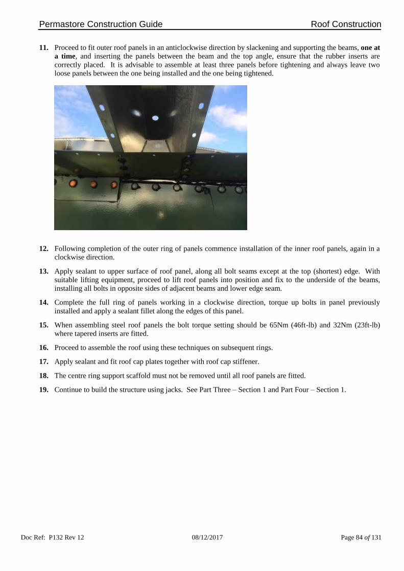
Permastore Construction Guide Roof Construction
Doc Ref: P132 Rev 12 08/12/2017 Page 84 of 131
11. Proceed to fit outer roof panels in an anticlockwise direction by slackening and supporting the beams, one at
a time, and inserting the panels between the beam and the top angle, ensure that the rubber inserts are
correctly placed. It is advisable to assemble at least three panels before tightening and always leave two
loose panels between the one being installed and the one being tightened.
12. Following completion of the outer ring of panels commence installation of the inner roof panels, again in a
clockwise direction.
13. Apply sealant to upper surface of roof panel, along all bolt seams except at the top (shortest) edge. With
suitable lifting equipment, proceed to lift roof panels into position and fix to the underside of the beams,
installing all bolts in opposite sides of adjacent beams and lower edge seam.
14. Complete the full ring of panels working in a clockwise direction, torque up bolts in panel previously
installed and apply a sealant fillet along the edges of this panel.
15. When assembling steel roof panels the bolt torque setting should be 65Nm (46ft-lb) and 32Nm (23ft-lb)
where tapered inserts are fitted.
16. Proceed to assemble the roof using these techniques on subsequent rings.
17. Apply sealant and fit roof cap plates together with roof cap stiffener.
18. The centre ring support scaffold must not be removed until all roof panels are fitted.
19. Continue to build the structure using jacks. See Part Three – Section 1 and Part Four – Section 1.

Permastore Construction Guide
Doc Ref: P132 Rev 12 08/12/2017 Page 85 of 131
PART SIX – Section 4
External Parallel Beam Roof Construction

Permastore Construction Guide Roof Construction
Doc Ref: P132 Rev 12 08/12/2017 Page 86 of 131
EXTERNAL PARALLEL BEAM STEEL PANEL ROOF CONSTRUCTION
All work must be carried out in accordance with all relevant local health and safety regulations. It is the
responsibility of the Contractor undertaking these works to consider each particular installation, its
environment and the specific risks therein prior to commencement of work. The Contractor shall
determine the protective equipment required by personnel and to plan the safe system of work that should
be adopted in order for the tasks to be carried out safely.
Work at height is the biggest single cause of fatal and serious injury in the construction industry. Avoid
work at height where it reasonably practicable to do so, e.g. by assembly at low level. Only authorised
persons/contractors adequately supervised, correctly equipped and trained in all aspects of the risks
involved and the equipment to be used should be employed to carry out this work. An appropriate risk
assessment and method statement must be in place prior to commencement of works, which should include
consideration of fragile roofs and/or roof lights.
1. External Parallel Beam roofs are constructed at ground level.
2. Assemble top ring of tank sheets including the top angle as detailed within Part Four – Section 1.
3. Commence roof build by setting up suitable load bearing scaffold to the diameter of the centre ring assembly
in the center of the tank at the correct height, refer to relevant drawing to support the roof during building.
4. Refer to relevant drawing for positions of inserts, sealer plates, bolt lengths etc. Roof top stiffener angle
galvanised parts to be primed with an appropriate Primer along joint face and allowed appropriate flash off
time before applying sealant.

Permastore Construction Guide Roof Construction
Doc Ref: P132 Rev 12 08/12/2017 Page 87 of 131
5. To assist when hanging very large steel panels, a hole is punched for attachment of a special lifting bracket.
After fitting the panel apply sealant around the hole, insert a store bolt and tighten to 65Nm (46ft-lb).
6. When assembling steel roof panels the bolt torque setting should be 65Nm (46ft-lb) and 32Nm (23ft-lb)
where tapered inserts are fitted.
7. Check that centre support ring assembly is level and set to the correct height above the top stiffener angle.
Refer to relevant drawing.
8. Check roof layout for start datum and install starter roof panels. Ensure that rubber inserts are correctly
positioned.
9. Install first 4 roof beams, placing them as near as practicable to 90° intervals. Refer to sketch for details of
beam end attachment.
10. Assemble the next 4 beams central to the 4 beams already installed. Proceed to install the rest of the beams
following the same procedure until all beams are in position.
11. Following completion of the outer ring of panels commence installation of the inner roof panels, again in a
clockwise direction.
12. Apply sealant to upper surface of roof panel, i.e. along the bolt seams except at the top (shortest) edge. With
suitable lifting equipment proceed to lift roof panel into position and fix to the underside of the beams
installing all bolts in opposite sides of adjacent beams and lower edges seam.
13. Complete the full ring of panels working in a clockwise direction, torque up bolts in panel previously
installed and apply a sealant fillet along the edges of this panel.
14. Proceed to assemble the roof using these techniques on subsequent rings.
15. Apply sealant and fit roof cap plates together with roof cap stiffener.
16. The centre ring support scaffold must not be removed until all roof panels are fitted.
17. Continue to build the structure using jacks. See Part Three – Section 1 and Part Four – Section 1.


Permastore Construction Guide
Doc Ref: P132 Rev 12 08/12/2017 Page 88 of 131
PART SIX – Section 5
Glass Reinforced Plastic (GRP) Roof Construction

Permastore Construction Guide Roof Construction
Doc Ref: P132 Rev 12 08/12/2017 Page 89 of 131
GRP ROOF CONSTRUCTION
All work must be carried out in accordance with all relevant local health and safety regulations. It is the
responsibility of the Contractor undertaking these works to consider each particular installation, its
environment and the specific risks therein prior to commencement of work. The Contractor shall determine
the protective equipment required by personnel and to plan the safe system of work that should be adopted
in order for the tasks to be carried out safely.
Work at height is the biggest single cause of fatal and serious injury in the construction industry. Avoid
work at height where it reasonably practicable to do so, e.g. by assembly at low level. Only authorised
persons/contractors adequately supervised, correctly equipped and trained in all aspects of the risks
involved and the equipment to be used should be employed to carry out this work. An appropriate risk
assessment and method statement must be in place prior to commencement of works, which should include
consideration of fragile roofs and/or roof lights.
1. GRP roofs are constructed at ground level.
2. The design and shape of GRP roofs vary considerably and for these reasons, generic guidelines will not be
provided.
3. Refer to roof manufacturer for product specific installation guidelines.

Permastore Construction Guide
Doc Ref: P132 Rev 12 08/12/2017 Page 90 of 131
PART SIX – Section 6
Pressure Testing of Roofs

Permastore Construction Guide Roof Construction
Doc Ref: P132 Rev 12 08/12/2017 Page 91 of 131
PRESSURE TESTING OF ROOFS
All work must be carried out in accordance with all relevant local health and safety regulations. It is the
responsibility of the Contractor undertaking these works to consider each particular installation, its
environment and the specific risks therein prior to commencement of work. The Contractor shall determine
the protective equipment required by personnel and to plan the safe system of work that should be adopted
in order for the tasks to be carried out safely.
Work at height is the biggest single cause of fatal and serious injury in the construction industry. Avoid
work at height where it reasonably practicable to do so, e.g. by assembly at low level. Only authorised
persons/contractors adequately supervised, correctly equipped and trained in all aspects of the risks
involved and the equipment to be used should be employed to carry out this work. An appropriate risk
assessment and method statement must be in place prior to commencement of works, which should include
consideration of fragile roofs and/or roof lights.
1. Where the project specification dictates a pressurised roof design is required the roof is designed to withstand
the internal pressures and/or vacuums specified in the relevant quotation document. Following construction
and hydrostatic testing it is important to test the roof to ensure that it is effectively sealed and meets the
specified test/operational/contractual conditions.
2. Equipment needed:-
a) Electric blower capable of achieving test pressure.
b) Electric extension cables to reach the top of the structure.
c) Manometer ('U' tube water gauge).
d) Pipe connection kit.
e) Appropriate personal safety equipment.
f) Knapsack sprayer.
3. Seal all tank outlet pipe flanges and access hatches.
4. Fill tank with water to operational level.
5. Install blower connection kit and pressurise roof to test pressure.
6. Use a water and detergent mixture to test all roof seams and flange connections.
7. Pressure must be maintained during the period of test, generally one hour maximum.
8. Mark any leaks that need to be repaired.
9. Release pressure from structure and repair any leaks. If leaks were repaired, re-pressurise and check they are
sealed.
10. It is advised that tests are carried out on a calm and cloudy day. Variations in temperature due to sun, rain or
wind can greatly affect internal pressure. These changes will cause pressures to fluctuate and will need to be
compensated for during the test.
11. Extreme fluctuations may cause a serious over/under pressurisation of roof resulting in damage if venting is
not adequate.
12. Ensure the roof is vented before draining internal water to prevent implosion.
13. When pressure testing to specific test/operational/contractual conditions it is advisable to ensure the
Customer's representative witnesses the test.
WHEN FILLING AND/OR DRAINING A TANK IN PREPARATION FOR OR FOLLOWING ROOF
PRESSURE TESTING IT IS IMPORTANT TO ENSURE THAT ROOF INSPECTION HATCHES,
VENTS, APERTURES ETC. ARE LEFT OPEN TO PREVENT AN OVER-PRESSURE OR VACUUM
SITUATION OCCURING WHICH MAY RESULT IN PERMANENT DAMAGE TO THE TANK
STRUCTURE.

Permastore Construction Guide
Doc Ref: P132 Rev 12 08/12/2017 Page 92 of 131
PART SEVEN – Section 1
Construction of Coated Steel Floors

Permastore Construction Guide Coated Steel Floor Construction
Doc Ref: P132 Rev 12 08/12/2017 Page 93 of 131
COATED STEEL FLOOR CONSTRUCTION
1. Prior to proceeding with the installation ensure you have read and understood the relevant drawings for the
type and size of floor to be assembled.
2. From the centre point of the prepared foundation mark a circle equivalent to the nominal tank diameter plus
150mm (6 inches).
3. Mark out the 0°-180° and the 90°-270° centre lines ensuring they are clearly identifiable outside of the
circle.
4. Lay base angles to confirm location of shim packs and install shim packs to the correct radius and level.
5. Lay the bitumen sand (8:1:1 sand:bitumen:cement) within the tank circle as detailed on the relevant drawing
and level with the shim packs.
6. Care must be taken to ensure the surface is level. A slight rise to the centre is desirable.
7. Lay polythene sheet and cover bitumen sand before installing floor.
8. Alternatively, Expanded Polystyrene (EPS) with characteristics in accordance with the following table may
be used in place of the bitumen sand and polythene sheet.
Tank Height Expanded Polystyrene Compressive Strength
30’ 150 kN/m2
45’ 200 kN/m2
60’ 250 kN/m2
90’ 300 kN/m2
9. Special care must be taken to protect the floor panels during construction of the floor and tank.
10. Before each sheet is laid, place a bead of sealant around the bolt shank, insert the bolts in readiness for
fitting the adjoining sheets, secure the bolts with the 'push on' retaining washer (Part Number 208059091).
11. Apply sealant ensuring a liberal covering around the protruding bolts.
12. For coated steel floors up to and including 21.347m (70ft) diameter, the perimeter holes for fixing the floor
to the foundation angles are pre-drilled.
13. For coated steel floors above 22.2m (73ft) diameter and above, the perimeter holes need to be drilled on site.
14. Lay the first panels (row 'A, B, C') and ensure that the first row of floor sheets is in a straight line before
tightening.

Permastore Construction Guide Coated Steel Floor Construction
Doc Ref: P132 Rev 12 08/12/2017 Page 94 of 131
FLOOR LAYOUT
15. Lay subsequent panels in sequential order as specified on relevant drawing.
16. Fit tapered inserts at the sheet overlap areas between the floor sheets and the base angles.
17. Fit full rows of sheets before tightening bolts using the standard torque settings to assist with alignment.
18. Fillet all sheet edges.
19. As there is no expansion pressure on a flat surface it is not necessary to use a joint expander during
construction.
20. Providing the procedures have been carefully followed there should not be any cause for leakage, however,
it is advisable for the crew leader to carefully inspect all areas of the sealing joints and fillets.

Permastore Construction Guide Coated Steel Floor Construction
Doc Ref: P132 Rev 12 08/12/2017 Page 95 of 131
This is a good opportunity to ensure a seal.
21. Dependent on the method of construction for the tank cylinder, protective nut caps should be fitted now if
jacks are not being using. Where jacks are being used to construct the tank the nut caps should not be fitted
until after the tank is constructed and all jack equipment removed.
22. Floor fixings should be treated with an appropriate Primer, allowed appropriate flash off and coated with the
appropriate sealant prior to fitting nut caps. See items 2, 5 and 6 under 'Standard Sealants and Primers'
Part 1 – Section 6.
23. Install the foundation angles and where they join fit the joint sealer angles as shown. Floor foundation
angle joint faces should be primed with an appropriate Primer, allowed appropriate flash off time before
applying appropriate sealant. See items 2 and 6 under 'Standard Sealants and Primers' Part 1 – Section 6.
Construct the first ring of tank cylinder sheets using the guidelines provided earlier.
24. Continue building the tank structure referring to ‘Assembly of Tanks and Silos from the Base Ring Upwards’
Part 3 Section 1.
25. When the structure is complete drill and fit the foundation bolts and PVC isolation washers and install the
internal perimeter sealant fillet.
26. Fillet the outside of the structure with concrete if specified/required.
27. Fit plastic nut caps to the floor area if not already installed.
PART NUMBER: 559299

Permastore Construction Guide Coated Steel Floor Construction
Doc Ref: P132 Rev 12 08/12/2017 Page 96 of 131
FLOOR PLATE – BASE ANGLE CONNECTION – BITUMINOUS SAND
SECTION THROUGH FOUNDATION BOLT – BITUMINOUS SAND

Permastore Construction Guide Coated Steel Floor Construction
Doc Ref: P132 Rev 12 08/12/2017 Page 97 of 131
FLOOR PLATE – BASE ANGLE CONNECTION – EXPANDED POLYSTYRENE
SECTION THROUGH FOUNDATION BOLT – EXPANDED POLYSTYRENE
28. The finished floor assembly MUST be wet swab tested at this stage (Part Ten – Section 1) and any repair
work undertaken. For details of suitable repair procedures refer to Permastore’s Inspection and Maintenance
Manual (Doc Ref: P110).

Permastore Construction Guide
Doc Ref: P132 Rev 12 08/12/2017 Page 98 of 131
PART EIGHT – Section 1
Construction of Structures with Conical Bases

Permastore Construction Guide Cone Construction
Doc Ref: P132 Rev 12 08/12/2017 Page 99 of 131
CONSTRUCTION OF STRUCTURES WITH CONICAL BASES
All work must be carried out in accordance with all relevant local health and safety regulations. It is the
responsibility of the Contractor undertaking these works to consider each particular installation, its
environment and the specific risks therein prior to commencement of work. The Contractor shall determine
the protective equipment required by personnel and to plan the safe system of work that should be adopted
in order for the tasks to be carried out safely.
1. Introduction
a) Cones and structures are designed to conform to the product being stored and customer requirements. The
connection and design techniques will remain similar.
b) Except for skirt mounted structures, a crane will be required to lift the structure and cone onto the supporting
steelwork.
c) Construction layout and techniques are the same as standard tank design, i.e. joint overlap and bolt torque.
d) A tapered insert is used at angle and sheet transition overlap areas.
e) Cone structures are designed to be supported by Glass-Fused-to-Steel or Fusion Bonded Epoxy sheets (skirt
mounted) or sectional steel (steel-frame mounted). The actual design being determined during the enquiry
stage when the operational and storage details are clear.
f) Skirt mounted cone structures can, in most cases, be assembled using the conventional installation equipment
traditionally used to construct PERMASTORE® tank and silos.
g) Steel frame mounted cone structures generally require specialist lifting equipment to ensure a quality and safe
construction.

Permastore Construction Guide Cone Construction
Doc Ref: P132 Rev 12 08/12/2017 Page 100 of 131
2. Skirt Mounted Structures
a) Ensure that for the final lift before the hip-joint is constructed, the jacks are taken down to their lowest
position. This will ensure the extra height required to install the hip-joint. Lift jacks to their highest
position and check that clearance is sufficient to assemble hip-joint and first row of skirt sheets.
b) Assemble the hip-joint leaving out cone sections at jack positions. Ensure that correct length bolts are used.
Do not fit bolts where the stiffener ring is to be connected. Leave bolts finger tight.
c) Assemble first row of sheets leaving out any bolts where stiffener ring is to be fitted.
d) Lower structure onto support and disconnect jack bolts.
e) Lower jacks and connect for next lift, raise structure sufficiently to allow completion of hip-joint and fitting
first row of cone sheets. After tightening cone sheets, assemble and fit external stiffener. Raise structure
again to assemble second row of skirt sheets.
f) Continue to build structure adding cone sheet rings and internal stiffener brackets as required. Fit internal
stiffener on completion of skirt sheets.
g) Fit cone outlet adapter to final row of cone sheets before they are tightened.

Permastore Construction Guide Cone Construction
Doc Ref: P132 Rev 12 08/12/2017 Page 101 of 131
3. Steel Frame Mounted Cone Structures
a) These structures are supported below the cone hip-joints directly onto a steel superstructure and will require
a crane on site, construction time will be dependent on method of build.
b) In most cases the top row of cone sheets would be assembled on a firm, level area of ground. Attach the
cone support ring and cylinder base angle.
c) Check that the ring of sheets are level, expand the vertical seams and tighten. Do not tighten the bolts from
the cone support ring to base angle at this stage.
d) Lift cone ring with crane using either internal bracing or a spreader frame to prevent distortion of the ring.
Further rows of cone sheets can be added at this stage depending on the size of crane employed.
e) Lift the cone onto the platform and bolt down. Tighten all bolts in base angle and channel.
f) Build the main structure on a firm level ground area using construction jacks. Ensure that the jacks are
securely anchored down. Fit a suitable lifting bracket to each vertical seam on the top row of sheets.
g) Using a spreader bar lift structure onto top of cone and couple up. Ensure that an appropriate sealant fillet
is applied inside to fully cover the hip-joint area.
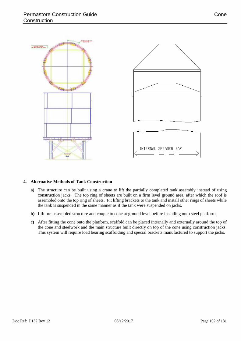
Permastore Construction Guide Cone Construction
Doc Ref: P132 Rev 12 08/12/2017 Page 102 of 131
4. Alternative Methods of Tank Construction
a) The structure can be built using a crane to lift the partially completed tank assembly instead of using
construction jacks. The top ring of sheets are built on a firm level ground area, after which the roof is
assembled onto the top ring of sheets. Fit lifting brackets to the tank and install other rings of sheets while
the tank is suspended in the same manner as if the tank were suspended on jacks.
b) Lift pre-assembled structure and couple to cone at ground level before installing onto steel platform.
c) After fitting the cone onto the platform, scaffold can be placed internally and externally around the top of
the cone and steelwork and the main structure built directly on top of the cone using construction jacks.
This system will require load bearing scaffolding and special brackets manufactured to support the jacks.


Permastore Construction Guide
Doc Ref: P132 Rev 12 08/12/2017 Page 103 of 131
PART NINE – Section 1
Assembly of Ancillary Products
Permastore Construction Guide Ancillary Products
Doc Ref: P132 Rev 12 08/12/2017 Page 104 of 131
GENERAL GUIDANCE NOTES
All work must be carried out in accordance with all relevant local health and safety regulations. It is the
responsibility of the Contractor undertaking these works to consider each particular installation, its
environment and the specific risks therein prior to commencement of work. The Contractor shall
determine the protective equipment required by personnel and to plan the safe system of work that should
be adopted in order for the tasks to be carried out safely.
Work at height is the biggest single cause of fatal and serious injury in the construction industry. Avoid
work at height where it reasonably practicable to do so, e.g. by assembly at low level. Only authorised
persons/contractors adequately supervised, correctly equipped and trained in all aspects of the risks
involved and the equipment to be used should be employed to carry out this work. An appropriate risk
assessment and method statement must be in place prior to commencement of works, which should include
consideration of fragile roofs and/or roof lights.
1. The ancillary products contained within this part of the Construction Guide have all been designed by
Permastore or have been technically assessed for suitability with our tank and silo products.
2. Although Permastore offer a comprehensive range of ancillary products, there are situations where
Distributors/Contractors manufacture their own ancillary products or where unique process requirements
dictate the use of special equipment, fixtures and fittings.
3. It is extremely important to ensure the technical suitability of any ancillary equipment that is not supplied by
Permastore and is to be mounted or fixed to one of our structures. The unnecessary introduction of dissimilar
metals, for example, can induce an electrolytic cell within the as-built tank.
4. Permastore cannot accept any responsibility for problems associated with the attachment/fitment of ancillary
equipment by others unless those products have been approved for use, in writing, by Permastore prior to
installation.
IF IN DOUBT, ASK.

Permastore Construction Guide Ancillary Products
Doc Ref: P132 Rev 12 08/12/2017 Page 105 of 131
ANCILLARY COMPONENTS
1. Protective Nut Covers
a) Plastic nut covers are supplied as standard with Glass-Fused-to-Steel floors, backfilled tanks and inner
annular tanks. They are provided to protect the exposed fixings only where there is a risk of contents or
environmental corrosion.
b) They can also be purchased separately for aesthetic purposes if required.
c) Check the relevant drawings for the position of the protective nut covers (eg backfilled tanks have nut
caps fitted in the area of backfill only, unless otherwise specified).
d) Once the nut has been tightened to the final torque, ensure that there is plenty of sealant squeeze-out
around the nut and washer, then push the protective nut cover onto the nut and washer.
e) Nut caps should be fixed when bolts have been torqued and sealant is still “wet.”

Permastore Construction Guide Ancillary Products
Doc Ref: P132 Rev 12 08/12/2017 Page 106 of 131
2. Flange Connectors
a) Flange connectors are available in a range of options, the standards being single, double or spigotted.
b) Refer to the relevant drawings for the correct orientation/position.
c) When installing flange connectors, apply sealant around the sheet aperture where the connector is in
contact with the tank or silo sheet. Position the connector and backing flange and fit the fixing bolts.
Tighten fixings to 65Nm (46ft-lb).
d) Fillet the internal edges of the connector assembly ensuring that the bore is not restricted by sealant.

Permastore Construction Guide Ancillary Products
Doc Ref: P132 Rev 12 08/12/2017 Page 107 of 131
3. Drilling and Cutting Holes in Tank or Silo Sheets
No cut-outs or fitments should be applied to the tank without prior consultation and advice.
a) Do not use disc grinders or flame-cutting equipment to cut holes in tank or silo sheets. Always use a drill
and jig-saw.
b) Always use eye protection when cutting or drilling sheets.
c) If the structure has been in use there may be potential hazards from toxic gases or substances.
d) Please refer to the Health and Safety information included within the .General Guidance Notes on page
98.
e) Mark the position of the hole to be drilled and dot punch the centre. Start with a small pilot drill and
gradually increase the drill size to the required size to the required hole diameter.
f) Apply masking tape over the areas of the openings to be cut. Mark out the opening and dot punch the
inside edge. Drill out to 10mm (13/32 inch) and using a jig-saw cut around the marking opening. After
cutting or drilling remove all traces of swarf and burred edges.
g) Ensure that all exposed edges of the Glass-Fused-to-Steel or Fusion Bonded Epoxy sheets have been
covered with sealant on completion of work.
4. Vents and Roof Hatches
a) Pre-assemble vent or hatch if required.
b) Apply sealant around roof aperture where the vent or hatch is in contact with the tank or silo sheet. Fit
and tighten fixing bolts to 50Nm (36ft-lb).
c) Glass reinforced plastic or aluminium fittings should only be tightened to 32Nm (23ft-lb).
d) Steel fitments should be tightened to 65Nm (46ft-lbs).

Permastore Construction Guide Ancillary Products
Doc Ref: P132 Rev 12 08/12/2017 Page 108 of 131
e) Fillet all internal and external edges with sealant.
Affix warning signs in accordance with ISO 3864. Graphical symbols. Safety colours and safety
signs. Design principles for safety signs and safety markings
5. Access Manways
a) Access manways are supplied as a complete assembly including a pre-cut aperture sheet and are designed
to complement the particular application required. Refer to relevant drawings for assembly detail and the
correct placing of all fasteners. The standard manway is 800mm diameter with a hinged cover to facilitate
safe and easy access.
b) Dependent upon the specification supplied, it may be necessary to use a mobile lifting rig to position the
manway frame.
c) Apply sealant around the sheet aperture inside and outside the structure, ensuring sufficient coverage to
effectively seal the flange plates.

Permastore Construction Guide Ancillary Products
Doc Ref: P132 Rev 12 08/12/2017 Page 109 of 131
d) Position the backing plate inside the structure as per the relevant drawings and insert a small quantity of
fixings.
e) Ensure that the correct bolts are utilised in all locations by referring to relevant drawings.
f) Position the external frame and fit nuts and washers to the locating fixings.
g) Insert the remaining fixings and tighten to 65Nm (46 ft-lbs.)
h) Fillet the internal and external edges of the frame assembly ensuring effective edge protection.
i) Position and fix the access door, using hex head bolts supplied, ensuring ease of operation and effective
closure. Tighten to 65Nm (46 ft-lbs.)
6. Ladders and Platforms
a) Ladders and platforms are supplied in various configurations according to the height, diameter, local
requirements and client specification. It is therefore very important to refer to the relevant drawing prior
to construction to ensure the correct layout details.
b) Pre-assemble the ladder platform sections and mark the position on the tank or silo of the ladder and
platform support brackets.
c) Ensure the correct length store bolts have been placed during tank or silo construction, refer to the
relevant drawing for details.
d) Apply sealant to the tank or silo wall and support brackets before installing the fixings.
e) The ladder sections and platform assembly can then be fitted to the support brackets at low level as the
tank or silo is being built.
f) Base ladders should be fitted to confirm suitability but removed before leaving site and handed to the
client for safe storage. Base ladders should only be fitted to accommodate controlled access.
g) Install the platform base onto the relevant support brackets and then complete the assembly by fitting the
upright support and handrails.
h) Several variations of the standard ladder and platform options are shown for reference.

Permastore Construction Guide Ancillary Products
Doc Ref: P132 Rev 12 08/12/2017 Page 110 of 131
SECTIONAL VIEW OF LADDER ASSEMBLY.

Permastore Construction Guide Ancillary Products
Doc Ref: P132 Rev 12 08/12/2017 Page 111 of 131
INDUSTRIAL LADDER AND PLATFORM OPTIONS

Permastore Construction Guide Ancillary Products
Doc Ref: P132 Rev 12 08/12/2017 Page 112 of 131
AGRICULTURAL LADDER AND PLATFORM OPTIONS
OPEN TOPPED AGRICULTURAL TANK LADDER ASSEMBLY WITH OPTIONAL
2M x 1M (6ft x 3ft) PLATFORM WITH CENTRE FLOOR HATCH
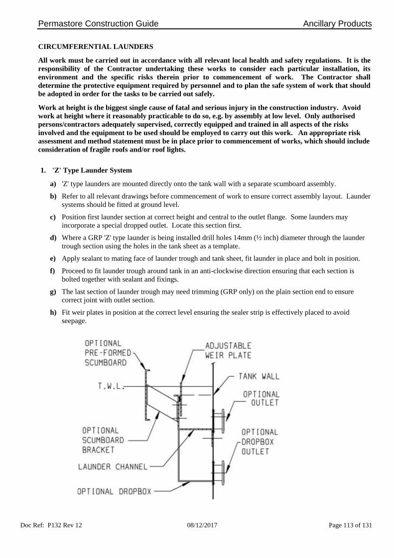
Permastore Construction Guide Ancillary Products
Doc Ref: P132 Rev 12 08/12/2017 Page 113 of 131
CIRCUMFERENTIAL LAUNDERS
All work must be carried out in accordance with all relevant local health and safety regulations. It is the
responsibility of the Contractor undertaking these works to consider each particular installation, its
environment and the specific risks therein prior to commencement of work. The Contractor shall
determine the protective equipment required by personnel and to plan the safe system of work that should
be adopted in order for the tasks to be carried out safely.
Work at height is the biggest single cause of fatal and serious injury in the construction industry. Avoid
work at height where it reasonably practicable to do so, e.g. by assembly at low level. Only authorised
persons/contractors adequately supervised, correctly equipped and trained in all aspects of the risks
involved and the equipment to be used should be employed to carry out this work. An appropriate risk
assessment and method statement must be in place prior to commencement of works, which should include
consideration of fragile roofs and/or roof lights.
1. 'Z' Type Launder System
a) 'Z' type launders are mounted directly onto the tank wall with a separate scumboard assembly.
b) Refer to all relevant drawings before commencement of work to ensure correct assembly layout. Launder
systems should be fitted at ground level.
c) Position first launder section at correct height and central to the outlet flange. Some launders may
incorporate a special dropped outlet. Locate this section first.
d) Where a GRP 'Z' type launder is being installed drill holes 14mm (½ inch) diameter through the launder
trough section using the holes in the tank sheet as a template.
e) Apply sealant to mating face of launder trough and tank sheet, fit launder in place and bolt in position.
f) Proceed to fit launder trough around tank in an anti-clockwise direction ensuring that each section is
bolted together with sealant and fixings.
g) The last section of launder trough may need trimming (GRP only) on the plain section end to ensure
correct joint with outlet section.
h) Fit weir plates in position at the correct level ensuring the sealer strip is effectively placed to avoid
seepage.

Permastore Construction Guide Ancillary Products
Doc Ref: P132 Rev 12 08/12/2017 Page 114 of 131
2. 'U' Type Launder System
a) 'U' type launders are mounted on brackets with an internal scum board.
b) Refer to all relevant drawings before commencement of work to ensure the correct assembly layout.
Launder systems should be fitted at ground level.
c) Install mounting brackets as detailed around the perimeter of the tank.
d) Position the first launder section central to the outlet flange. Some launders may incorporate a special
drop box. Locate this section first.
e) Proceed to mount launder trough on the support brackets around the tank in an anti-clockwise direction,
ensuring that each section is bolted together with sealant and fixings supplied.
f) Fix launder trough to mounting brackets using pre-punched holes, ensuring good sealant application
around fixings.
g) Fit weir plates in position at the correct level ensuring the sealer strip is effectively positioned to avoid
seepage.

Permastore Construction Guide Ancillary Products
Doc Ref: P132 Rev 12 08/12/2017 Page 115 of 131
BAFFLES AND BAFFLE WALLS
All work must be carried out in accordance with all relevant local health and safety regulations. It is the
responsibility of the Contractor undertaking these works to consider each particular installation, its
environment and the specific risks therein prior to commencement of work. The Contractor shall
determine the protective equipment required by personnel and to plan the safe system of work that should
be adopted in order for the tasks to be carried out safely.
Work at height is the biggest single cause of fatal and serious injury in the construction industry. Avoid
work at height where it reasonably practicable to do so, e.g. by assembly at low level. Only authorised
persons/contractors adequately supervised, correctly equipped and trained in all aspects of the risks
involved and the equipment to be used should be employed to carry out this work. An appropriate risk
assessment and method statement must be in place prior to commencement of works, which should include
consideration of fragile roofs and/or roof lights.
1. Internal Baffles
a) Internal baffle assemblies are utilised to provide a homogenous mixture of contents in process tanks.
b) Directly dependent on the height of the tank, the baffle assembly may be designed as a single piece
structure or a modular concept.
c) Refer to all relevant drawings before commencement of work to ensure correct assembly layout. Baffle
assemblies and baffle walls should be installed at ground level.
d) Apply sealant to the contact surfaces and fit vertical support angle frames to the tank wall.
e) Fit baffle plates to the angle frame.

Permastore Construction Guide Ancillary Products
Doc Ref: P132 Rev 12 08/12/2017 Page 116 of 131
2. Baffle Wall
a) Baffle walls are utilised to separate different sections or processes within a tank.
b) Apply sealant to contact faces and fit vertical support angles to inner and outer tank.
c) Fit baffle wall to support angles.
d) Fit top angle to baffle wall using splice plates to join to inner tank.
e) After fitting floor angles drill out concrete and fit expanding anchor bolts.
f) After completion of baffle walls install concrete haunch over floor angles if specified.
g) Apply sealant to contact faces and fit weir weld assembly to inner tank.
h) Fit splice plates to weir weld assembly to join to top stiffener angles.

Permastore Construction Guide Ancillary Products
Doc Ref: P132 Rev 12 08/12/2017 Page 117 of 131
AGRICULTURAL VALVE KIT
Persons working in and around tanks, silos, digesters and waste system receiving pits are at risk of
being overcome by hazardous gases including hydrogen sulphide and methane, among others, with
potentially fatal consequences. Any internal inspection or maintenance work must be carried out by
operatives who are suitably trained and equipped for working in confined spaces.
All work must be carried out in accordance with all relevant local health and safety regulations. It is the
responsibility of the Contractor undertaking these works to consider each particular installation, its
environment and the specific risks therein prior to commencement of work. The Contractor shall
determine the protective equipment required by personnel and to plan the safe system of work that should
be adopted in order for the tasks to be carried out safely.
1. Sluice gate
a) Refer to approved valve assembly drawings.
b) When installing the valves and trunking or pipework, ensure any PVC joints are glued correctly.
c) Support the pipe or trunking and valves in the trench, to allow a minimum of 150mm (6 inches) concrete
cover over the pipework.
d) Valves must be installed with flow direction arrow facing the reception pit to ensure that the valve plate
is under flow pressure against the seal.
e) Wrap the entire length of PVC pipework in polythene sheeting.
f) Care should be taken when pouring the concrete to ensure the pipework or trunking is not disturbed or
damaged.
g) Concrete clearance must be maintained at the top of the valve to allow for top plate removal.
h) Refer to item 3 Drilling and Cutting Holes in Tank or Silo Sheets if required.

Permastore Construction Guide Ancillary Products
Doc Ref: P132 Rev 12 08/12/2017 Page 118 of 131
SACRIFICIAL ANODE CATHODIC PROTECTION SYSTEM
1. There are some applications in which the process requirements or commercial factors dictate that future
access for routine inspection and maintenance is impractical.
2. For coated steel tanks where cathodic protection required, the use of sacrificial anodes, rather than
impressed current, is the preferred solution. Sacrificial anode cathodic protection is a specialist service
for which we recommend seeking professional advice. Where, in discussions with the owner, the
purchaser recommends that cathodic protection should be fitted then the purchaser should source a
sacrificial anode cathodic protection system through a local NACE registered supplier. Local suppliers
can be found by accessing the following web site:
http://www.naceinstitute.org/cstm/education/certification/certsearch.aspx.
3. Refer to “Guidance Notes for the Application and Use of Sacrificial Anode Cathodic Protections Systems”
(Doc Ref: P145.)

Permastore Construction Guide
Doc Ref: P132 Rev 12 08/12/2017 Page 119 of 131
PART TEN – Section 1
Low Voltage Continuity Testing on Site

Permastore Construction Guide Testing on Site
Doc Ref: P132 Rev 12 08/12/2017 Page 120 of 131
LOW VOLTAGE CONTINUITY (WET SWAB) TESTING ON SITE
1. All structures should be wet swab tested on the internal surface following construction.
2. We recommend that for tall structures being built with jacks, that a check on the continuity of the internal
Glass-Fused-to-Steel or Fusion Bonded Epoxy coating is conducted on a ring by ring basis during
construction. This will identify any minor repairs that may be necessary following construction and will
reassure the end user that the product has a defect free containment surface.
3. The internal surface of the structure should be clean and free of surface contaminants. Testing is carried out
using an Elcometer Model 270 Wet Swab Unit, or similar, set at 9 volts. The test sponge shall be wet but
not saturated with water containing a small amount of detergent to reduce surface tension.
4. In the unlikely event that a discontinuity is found the area must be repaired in accordance with Permastore’s
Tanks & Silos Inspection & Maintenance Manual (Doc Ref: P110) or Epoxy Coated Tanks & Silos
Inspection & Maintenance Manual (Doc Ref: P269).
5. The area of repair shall again be subjected to low voltage testing to prove satisfactory repair.
6. Inspect the structure with the customer's representative and assuming everything is in order request his
certification of satisfactory completion of the Low Voltage Continuity Test.

Permastore Construction Guide
Doc Ref: P132 Rev 12 08/12/2017 Page 121 of 131
PART TEN – Section 2
Guidelines for the filling and testing of
PERMASTORE® Glass-Fused-To-Steel, Epoxy Coated & Stainless Steel Tanks

Permastore Construction Guide
Doc Ref: P132 Rev 12 08/12/2017 Page 122 of 131
GENERAL INFORMATION
All work must be carried out in accordance with all relevant local health and safety regulations. It is the
responsibility of the Contractor undertaking these works to consider each particular installation, its
environment and the specific risks therein prior to commencement of work. The Contractor shall
determine the protective equipment required by personnel and to plan the safe system of work that should
be adopted in order for the tasks to be carried out safely.
Work at height is the biggest single cause of fatal and serious injury in the construction industry. Avoid
work at height where it reasonably practicable to do so, e.g. by assembly at low level. Only authorised
persons/contractors adequately supervised, correctly equipped and trained in all aspects of the risks
involved and the equipment to be used should be employed to carry out this work. An appropriate risk
assessment and method statement must be in place prior to commencement of works, which should include
consideration of fragile roofs and/or roof lights
Persons working in and around tanks, silos, digesters and waste system receiving pits are at risk of
being overcome by hazardous gases including hydrogen sulphide and methane, among others, with
potentially fatal consequences. Any internal inspection or maintenance work must be carried out by
operatives who are suitably trained and equipped for working in confined spaces.
1. The following are guidance notes for the filling, hydraulic testing and emptying of Permastore open topped
or roofed tanks including pressurised installations.
2. Prior to filling, the structure should be inspected for signs of damage which may have occurred during
construction. Any areas of damage should be repaired using the repair method as detailed in P110 “Glass-
Fused-to-Steel Tanks & Silos Inspection & Maintenance Manual”, P269 “Epoxy Coated Tanks & Silos
Inspection & Maintenance Manual” or P293 “Stainless Steel Inspection & Maintenance Manual.”
3. It is essential that the sealant has cured prior to hydraulic testing. Sealant cure times are dependent on
temperature and humidity. Typical cure rates are 2mm/24hours @ 23°C & 50% RH resulting in full cure
within a period of approximately 5 days. As a rule of thumb, cure rate doubles for each 10°C drop in
ambient temperature. Please refer to sealant manufacture’s guidelines for further information.
4. The tank must be checked to ensure that all materials, tools and equipment have been removed, and a final
check must be made to ensure that no personnel remain inside the confines of the tank. The access cover
panel should be installed using the gasket and fixings supplied.
5. Changes in environmental conditions such as ambient temperature, wind-speed and humidity can lead to
rapid and substantial changes in air pressure inside roofed tanks even if the roof is not nominally airtight or
pressurised. Sufficient venting must be provided at all times to avoid negative or positive pressures
developing inside the tank due to changes in environmental conditions and the consequences of filling or
emptying of the contents.
6. Fit blanking plates to all connections using gaskets, except for connections providing venting. Ensure vents
are open and unobstructed.
7. Turn all valves connected to pipework adjacent to tank to the stop / off position.
8. The tank is designed to take the full hydraulic load of the contents, provided that there is negligible inertial
and impact loading due to tank filling. Connections and associated pipe work shall be designed to minimise
loads on the tank wall.
9. If the tank is to be disinfected, this shall be carried out in accordance with P 173 “Guidance Notes for the
Disinfection of Permastore Glass-Fused-to-Steel Water Storage Tanks.”
10. The hydraulic load applied to the tank shall not be greater than that for which the structure has been
designed.
11. The test liquid shall be no more aggressive than that for which the structure has been designed.

Permastore Construction Guide
Doc Ref: P132 Rev 12 08/12/2017 Page 123 of 131
12. The tank should not be left unsupervised during the filling or draining processes.
13. Minor leaks may occur around the base while the hydrophilic seal develops.
14. In the unlikely event of signs of a major leak during filling, the filling operation shall be stopped and the
build crew team leader contacted who should review the situation and, having sought appropriate advice,
recommend the course of action to be taken.
15. Any leaks should be repaired in accordance with P110 “Glass-Fused-to-Steel Tanks & Silos Inspection &
Maintenance Manual”, P269 “Epoxy Coated Tanks & Silos Inspection & Maintenance Manual” or P293
“Stainless Steel Inspection & Maintenance Manual.”
16. Unless specific test requirements are detailed in the client’s specification the normal test period should be
adopted, being; once filling is completed the tank should be left to stand for a minimum of 48 hours with a
visual inspection for leaks ½ to 1 hour after filling and at the end of the test period.
17. The test operator is to ensure that sufficient venting is available to the roof area to match emptying rate. This
rate is to be determined by the test operator in accordance with the ventilating facilities in place during the
draining operation.


Permastore Construction Guide
Doc Ref: P132 Rev 12 08/12/2017 Page 124 of 131
PART TEN – Section 3
Checklist Following Construction
Permastore Construction Guide Checklist
Doc Ref: P132 Rev 12 08/12/2017 Page 125 of 131
CHECKLIST AFTER CONSTRUCTION
1. Ensure sufficient sealant has been applied correctly:
a) To provide full cover to all areas of sheet overlap;
b) To provide a squeeze out of sealant around bolt heads, nuts and washers.
2. Ensure that bolts have been fitted to all holes that were used for joint expansion or jack location.
3. Ensure that all sheet edges have been pointed correctly to give full protection both internally and externally.
4. Any damage is to be repaired in accordance with P110 “Glass-Fused-to-Steel Tanks & Silos Inspection &
Maintenance Manual”, P269 “Epoxy Coated Tanks & Silos Inspection & Maintenance Manual or P293
Stainless Steel Inspection & Maintenance Manual.”
5. Ensure that all ancillaries attached to tank or silo sheets have been fully coated with sealant on contact surfaces
before being bolted.
6. Ensure that all tapered inserts have been used in appropriate areas at top and bottom angles as indicated on
relevant drawings. Correct torque: 32Nm (23ft-lb.)
7. Ensure that all levels and concentricity are in accordance with recommendations.
8. Ensure that all the bolts are tightened to the specified torques.
9. Ensure that that the peripheral base seal has been applied correctly and checked for adhesion.
10. Ensure that all ancillary items securely fastened.
11. Ensure that the full structure has been examined carefully and that coated structures are swab tested internally
to identify any installation damage and that any damaged areas have been repaired.
12. Check that the serial plate has been fitted.
13. Check that the Safety Awareness signs provided within the tank or silo construction kit are installed as
instructed.
14. Ensure the structure has been left in a safe and secure condition following installation and testing. For
example:
a) Base ladders removed and stored safely by the client.
b) Access doors fitted/closed correctly
c) Pressure test blanking plates removed.
d) No debris/fixings left in the tank or silo that could damage process equipment.
e) Any other obvious matter requiring attention.
15. Ensure all packing and waste materials have been cleared up, disposed of properly and the site is left tidy. All
COSHH substances and contact packaging must be disposed of in a safe manner commensurate with the
manufacturer’s data sheet.
16. Inspect the structure in accordance with P110 “Glass-Fused-to-Steel Tanks & Silos Inspection and
Maintenance Manual”, P269 “Epoxy Coated Tanks & Silos Inspection and Maintenance Manual” or P293
“Stainless Steel Inspection & Maintenance Manual.”
17. Finally, complete section B of the Inspection Report of the appropriate Inspection and Maintenance Manual.

Permastore Construction Guide
Doc Ref: P132 Rev 12 08/12/2017 Page 126 of 131
PART ELEVEN – Section 1
Troubleshooting

Permastore Construction Guide Troubleshooting
Doc Ref: P132 Rev 12 08/12/2017 Page 127 of 131
TROUBLESHOOTING
All work must be carried out in accordance with all relevant local health and safety regulations. It is the
responsibility of the Contractor undertaking these works to consider each particular installation, its
environment and the specific risks therein prior to commencement of work. The Contractor shall
determine the protective equipment required by personnel and to plan the safe system of work that should
be adopted in order for the tasks to be carried out safely.
Work at height is the biggest single cause of fatal and serious injury in the construction industry. Avoid
work at height where it reasonably practicable to do so, e.g. by assembly at low level. Only authorised
persons/contractors adequately supervised, correctly equipped and trained in all aspects of the risks
involved and the equipment to be used should be employed to carry out this work. An appropriate risk
assessment and method statement must be in place prior to commencement of works, which should include
consideration of fragile roofs and/or roof lights.
1. Introduction
a) This section has been compiled to assist the construction team to resolve minor assembly issues and
undertake replacement or modification work.
b) One of the features of a modular bolted steel tank or silo is the ability to modify the structure on site to
accommodate new or changed process conditions. It is also possible to extend some structures in
height using either a top or bottom extension but in all cases, seek advice and written approval from
Permastore to ensure suitability of proposed change.
2. Removal of Flat Spots on the Corner Joints of a Structure
a) Remove all bolts surrounding the four corner joints, clean, apply new sealant in the joints and loosely
install new bolts.
b) Secure a wooden support inside the structure with an M10 (⅜ inch) diameter eye bolt through the bolt
hole in the shear joint and pull out flat spot to the correct shape. This is best done using a chain block
or similar anchored to a suitable pulling point. After pulling out flat spots tighten bolts to the correct
torque. Remove chain block, replace eye bolt and apply sealant fillets to blend in with the existing
fillets.
3. Removing and Replacing a Tank Sheet
a) If the structure has been in use there may be potential hazards from toxic gases or substances. A
suitably qualified person should assess all risks prior to any works being performed.
b) The structure must be drained completely and the affected area thoroughly dried before commencement
of repair.
c) Set up scaffold to a working height on the outside and inside of tank adjacent to where sheet is to be
removed.
d) To remove the sheet, carefully take out all the sheet fixing bolts from the sheet overlaps. It may be
necessary to remove the bolts on adjoining sheets at the four sheet overlap joint for the distance of
about 300mm (12 inches). Using wooden wedges gently prise the sheet joints apart. Using suitable
lifting equipment remove tank sheet. Thoroughly clean sealant from the sheet overlap joints.
e) To fit the replacement sheet, sealant must be applied to all the overlap faces and with wooden wedges
prise a gap between the adjoining sheets as with removal. When the replacement sheet is lowered into
position with suitable lifting equipment, ensure sealant is applied between the prised open joints and
applied to the replacement bolts before fitting.
f) When all bolts are fitted tighten to the standard torque and apply sealant fillets over sheet edges to
blend in with the existing fillets.
4. Leakage Repairs
a) Any leaks must be repaired in accordance with Permastore’s Tanks & Silos Inspection & Maintenance
Manual (Doc Ref: P110) or Epoxy Coated Tanks & Silos Inspection & Maintenance Manual (Doc Ref:
P269).

APPENDIX A
Doc Ref: P132 Rev 12 08/12/2017 Page 128 of 131
8
1
2
4
6
5
7
3

APPENDIX A
Doc Ref: P132 Rev 12 08/12/2017 Page 129 of 131
9
10
12
11
13

APPENDIX A
Doc Ref: P132 Rev 12 08/12/2017 Page 130 of 131
14
15
16
18
17

APPENDIX A
Doc Ref: P132 Rev 12 08/12/2017 Page 131 of 131
p
19
20 21
22 23