construction history of the composite framed tube ... r.pdf · story cdc building in houston,...
TRANSCRIPT
Construction history of the composite framed tubestructural system
This paper examines the construction history of tallbuilding s designed during the latter portion of thetwentieth century. Fazlur Khan was able to capitalizeon the inherent strengths of steel and concrete byusing them in conjunction with a framed tube system.
This idea involves a novel construction process,which takes advantage of the virtues of structuralsteel and reinforced concrete. Early applications ofthis system in the mid-1960's were in the 35-storyGateway III Building in Chicago, Illinois and the 25story CDC Building in Houston, Texas. Composite
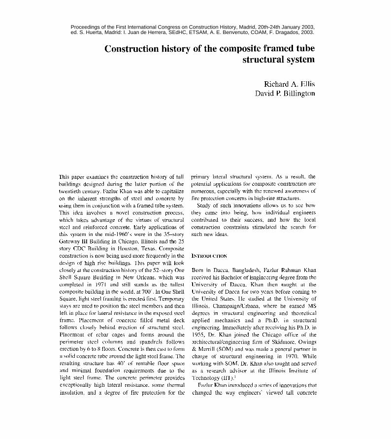
construction is now being used more frequently in thedesign of high rise buildings. This paper will lookclosely at the construction history of the 52-story OneShell Square Building in New Orleans, which wascompleted in 1971 and still stands as the tallestcomposite building in the world, at 700'. In One ShellSquare, light steel framing is erected first. Temporarystays are used to position the steel members and then
left in place for lateral resistance in the exposed steelframe. Placement of concrete filled metal deckfollows closely behind erection of structural steel.Placement of rebar cages and forms around theperimeter steel columns and spandrels followserection by 6 to 8 t1oors. Concrete is then cast to forma solid concrete tu be around the light steel frame. Theresulting structure has 40' of rentable t100r space
and minimal foundation requirements due to thelight steel frame. The concrete perimeter providesexceptionally high lateral resistance, some thennal
insulation, and a degree of fire protection for the
Richard A. Ellis
David P. Billington
primary lateral structural system. As a result, the
potential applications for composite construction arenumerous, especially with the renewed awareness offire protection concems in high-rise structures.
Study of such innovations allows us to see howthey came into being, how individual engineers
contributed to their success, and how the localconstruction constraints stimulated the search forsuch new ideas.
INTRODUCTlON
Born in Dacca, Bangladesh, Fazlur Rahman Khanreceived his Bachelor of Engineering degree from theUniversity of Dacca. Khan then taught at theUniversity of Dacca for two years before coming tothe United States. He studied at the University oflIlinois, Champaign/Urbana, where he eamed MSdegrees in structural engineering and theoreticalapplied mechanics and a Ph.D. in structuralengineering. Immediately after receiving his Ph.D. in1955, Dr. Khan joined the Chicago office of thearchitectural/engineering firm of Skidmore, Owings& Merrill (SOM) and was made a general partner incharge of structura] engineering in 1970. Whileworking with SOM, Dr. Khan a1so taught and served
as a research advisor at the lIlinois Institute ofTechnology (IIT).l
Fazlur Khan introduced a series of innovations that
changed the way engineers' viewed tall concrete
Proceedings of the First International Congress on Construction History, Madrid, 20th-24th January 2003, ed. S. Huerta, Madrid: I. Juan de Herrera, SEdHC, ETSAM, A. E. Benvenuto, COAM, F. Dragados, 2003.
800 R. A. Ellis, D. P. Billington
building structures. He could not have done thiswithout the close coUaboration with his partners andcolleagues at Skidmore, Owings, and Merrill.Especially the architect Bruce Graham and the
architect-engineer Myron Goldsmith were crucial to
Khan's success. AIso there were exceUent structuralengineers who worked with him, most prominentlyHal Iyengar and John Zils. Khan was also fortunate to
be able to work closely with developers and buildersas he thought through his new ideas. Fazlur Khan'sexperience of working with developers and buildersallowed him to develop new systems. The resultingstructures, which integrated engineering andconstruction practice, cou]d be built economicaUy.He died in mid-career with many plans uncompletedbut he nevertheless achieved the status of structuralartist whose works will be studied long after the
twentieth century. 2
STRUCTURAL TUBE SYSTEM
In 1961, Dr. Fazlur Khan began to seek structuralsystems that would aUow for construction of tallerbuildings without paying the «premium for height»
which resulted from the wind loadings. Herecognized that overcoming this premium wouldrequire new systems and new construction practices,in the tradition of the technology-oriented stylecommon]y referred to as the Chicago School of
Architecture.3 This led him to the creation of the
framed-tube, in which exterior cJosely spacedcolumns and deep spandre]s pro vide the entire lateralresistance. The Wor]d Trade Center emp]oys thisscheme on a grand scale. The exterior co]umns havenarrow spacing and the windows are reces sed,creating the ilJusion of solid tubes.
Khan first used the framed-tube in the 43-story
DeWitt Chestnut Apartment Building in Chicago,completed in ] 965. Here, perimeter co]umns arespaced at 5.5 feet on centers and the spandrels
between columns at each ]evel are about 2 feet deep.The close column spacing expresses the idea of aso]id tube perforated by holes that create the
windows.StructuraIJy, the framed-tube is superior to a rigid
frame because it places material on the exterior of thebuilding, where it wiJI contribute most to the moment
of inertia and maximize the lateral stiffness of the
building. The DeWitt Chestnut Building al so has arelatively smaU t100r plan, so by moving the lateralsystem from the core to the exterior of the buildingva]uable floor space is freed. The entire interiorstructura] system is secondary -designed to carryon]y gravity loads to the ground leve!.
In 1963 Khan started to contemplate a new systemin which latera] force s were carried primarily by aninterior shear waU coreo The resulting 38-storyBrunswick Bui]ding in Chicago was designed with asubstantial concrete shear waU coreo Much of thebuilding' s service machinery were also located in thecoreo Perimeter columns were placed at 9 feet 4inches on centers and tied by deep spandrel beams ateach floor. In making a quick check of the designcaJculations it became evident to Khan that theexterior framing was nearJy as stiff as the shear waUcore acting as a vertical cantilever.4
Khan had created an efficient system in whichlateralloads are carried both by the exterior trame andinterior shear waU core through shear wall-frameinteraction. According to Khan, «One of theadvantages of the shear waU frame interaction systemis that it exists in every reinforced concrete buildingwith shear waIJs, whether the trame is deliberate]ydesigned for it or not, simply because every joint
in a reinforced concrete structure when castmonolithicaUy acts as in a rigid frame».5 In theBrunswick Building, this system also created 38-feetof unobstructed space by aIJowing the interior
columns aJl to be placed in the bui]ding's coreo
COMPOSITE CONSTRUCTION
By employing various structural systems in buildings
of steel and bui]dings of reinforced concrete, Khanwas able to gain a clear sense of the advantages anddisadvantages of each materia!. He then developed
a system to take advantage of a steel structurecombined with one of a reinforced concrete. This isthe basis for what became known as the SOM-Composite System.6
For framed tube structures the system consists ofan exterior frame in reinforced concrete. The interiorfloor framing is erected entirely with structural steel.Concrete offers properties for inherent fire protectionwith out resorting to the separate cJadding used in
fire protected stee] surfaces. Under norma] service
Construction History of the Composite Framed Tube Structura1 System 801
the concrete tube will serve as a layer of insulationcausing a reduction of heating and cooling loads. The
lateral stiffness of the concrete tube is often adequate
to carry the wind loads, while the steel tloor framingcarries most of the gravity dead loads, except for theweight of the concrete tube itself.
This also avoids the disadvantages of concreteconstruction. Namely: interior concrete shear wallscontribute greatly to the loss of tloor efficiency andconcrete construction is typically much slower thansteel erection. In most high-rise structures, tloorframing contributes to 75-80% ofthe total material in
the structure.7 Composite construction practices canresult in construction cycles that are as fast asstructural steel erection, demonstrated first in the50-story CDC Building in Houston, Texas where theentire steel trame for fi ve stories was erected beforeconcrete casting commenced. This separated the twowork forces necessary for the two materials andallowed a fast construction pace. Precast modularwindow framing units were attached during steelerection and then used as forms for the casting of theexterior concrete frame. The construction cycle was 3days per floor for all 50 tloors. Khan designed similar
composite construction projects at Qne Shell Square
in New Qrleans and Union Station in Chicago whereconstruction cycles ere on par with those for steelerection. Since normal concrete construction cyclescan be in excess of 7 days per floor, the savings intime allowed by composite construction reduced cost
as much as 33%.8
QNE SHELL SQUARE
Completed in 1970, Qne Shell Square remains the
tallest building in New Qrleans at 52 stories. FazlurKhan designed it for the developer Gerald D. Hines.Qne Shell Square is most interesting from a structuralperspective because of innovative use of steel and
concrete. The composite system that was developedby Khan is efficient because it capitalizes on the
¡nherent strengths of each material. Material selection
was driven by a desire to maximize the rentable tloorspace and overall stiffness under lateral loads whileminimizing the dead weight and total cost per area ofthe building.
Qne Shell Square was designed with a composite
structural system that combined steel floor framing
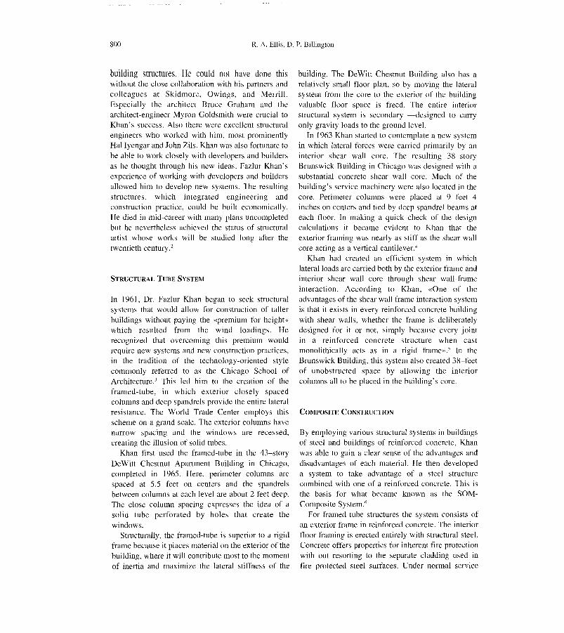
Figure 1Facadc of One Shell Square. New Orleans
and a steel core with concrete encased steel columnson the periphery of the building. Efficiency wasgaincd through the use of steel in the floor frame
because the ductile metal is approximately 9 timesstronger than concrete and has a higher modulus ofelasticity (29,000 ksi for steel vs. 3,200 ksi forconcrete) so more compact sections could be used to
achieve the same strength. Compact sections areessential in steel frame design because steel is a verydense material. However, well-designed steel floorbeams are able to span long distances. In Qne ShellSquare the floor-framing scheme aIJowed for 40' of
column free space around the buildings braced steelcoreo Steel floor traming was also desirable because it
could be erected quickly when compared to a

802 R. A. Ellis, D. P. Billington
concrete frame.9 The World Trade Center Towerswere marvelous examples of a framed tube madeentirely of structural steel.
In very tall buildings, like One Shell Square, lateralloads dictate design. Lateral loads can result fromseismic activity Jike an earthquake but in NewOrleans the criticar lateralloads applied to structuresare wind. Structures must be designed with adequatestiffness to counteract the overstressing momentresulting from wind. A high premium would have to
be paid for the additiona] material to stiffen a steelstructure of this height. In the World Trade Centermass tuned dampers were used at each story tominimize lateral sway from wind, which contributed
to the structure's $700 million price tag.The use of reinforced concrete on the perimeter of
One Shell Square allowed designers to overcome thispremium. The stiff concrete columns and spandreJsformed a braced tube, which provided lateralresistance for the entire structure. A concrete framedtube is ideal for composite systems because it placeslarge heavy sections on the perimeter of the building,
as far as possible from the centroid, where they willcontribute most to the moment of inertia of thestructure. The moment of inertia, modulus ofelasticity, and unbraced length determine the stiffness
of a structure. The perimeter composite columns ofOne Shell Square have a close spacing of 10'. Thisgives the spandrels a shorter unbraced length, furtherstiffening the structure against lateral loads.
Construction Sequencing
The construction sequencing of One Shell Square wasan most innovative aspect of the composite designoSteel erection and concrete casting had to be keptseparate if they were to occur on the same site. Eachrequires a specialized labor force and equipment.
Interference between the two could causecomplications and resuJt in delays. To avert thisproblem construction of One Shell Square began with
traditional steel frame erection.Steel sections were positioned using temporary 3/4"
cable stays. The stays were left in place duringconstruction of the steel trame to provide additionalstiffness to the compact sections. In this initial phasethe braced core carried all lateral loads so theperimeter columns were sized to carry mini mal
gravity loads. The largest steel section used on the
perimeter was W8 x 67, which can be compared tothe large WI4 x 550 and built-up sections used in thecore of the structure. Figure 2 shows the dimensionsof one buih-up co]umn at the base of the structure.The core was stiff enough to allow erection of lOto]2 stories of exposed steel. Placement of metal deck
and casting of the fIoor s]ab follow closely behinderection of the frame.
~M
~<O 4" WEB;.
~
Figure 2Construction detail of One Shell Square steel perimetercolumn
4'-1"
14"
#6REBARS
~
~~
Figure 3
Construction detail of One Shell Square composite
perimeter column

Construction History of the Composite Framed Tube Structural System S03
Once steel erection had progressed to a prescribedheight of 9 stories, concreting of the building's
perimeter began. Rebar cages and forms wereattached directly to the exterior steel frame sections.Concrete was then poured into the forms, completelyencasing the exterior light steel frame (Figure 3).Composite action begins once the columns becomemonolithic with the floor slab and spandrels. Casting
of concrete and steel erection then proceededsimultaneously until both reach the completedbuilding height of 52 stories.
Structural Analysis
The efficiency gained by the composite system can beeasily observed through an analysis of the
construction sequence. Construction was divided into5 phases in order to identify critical points in the
f1.2I
Fl9
1'1.1
Phase 1 Phase 2 Phase 3Figure4One Shell Square construction phases
sequence. SAP2000 was used to create a 2-D modelof the structure. Figure 4 shows the proportions of theSAP models that were used for the 5 phases ofconstruction. The section properties and dimensionsfor the columns used in each model appear in Table l.The model takes the equivalent moment of inertia,cross-sectional area, and dead weight from one bay ofthe buildings trame and applies them to aplanarframe with equivalent properties.
The effective area of one bay is outlined inFigure 5, which shows the actual floor-framing plan
for One Shell Square. Each construction phase wassubjected to a combination of wind, dead, and liveloado The output, however, has been formatted toshow the building's response from each loadseparately. In this manner, it can be determined which
load must have govemed designo As expected the
building's response to wind load was the mostcritical, so that is what is discussed here.
Fl52Fl52
Fl29 f129
/ \/'
,/
F129
FI. 9FI. 9
FlI FlIFLI
l
Phase 4 Phase 5

-1
í -- i~-
1
--
1-
I
804 R. A. ElIis, D. P. Billington
t8Si"J>Qi;'<>\!,iIV
.,?;,c,.o"
ó,
Figure 5
One Shell Square l100r framing plan
The wind pressure profile used in this analysis wasgenerated using the method prescribed by theAmerican Nationa] Standard's Institute. In thismethod, wind pressure varies with wind velocity,
which is a function of elevation. New Orleans falls in
a region that is subject to hurricanes on a regular basisso a basic wind speed of ]40 mph was used todetermine wind pressure. The wind pressure for anygiven story was then multipJied by the tota] facing
area of that story to obtain the design wind load. Thefollowing equation is used to determine the design
wind pressure at al! elevations;
p =qPCf
where:
q, = velocity pressure evaluated at height zG =Gust factor based on exposure category
CI =pressure coefficient
A gust factor (G) of .8 was used for this exposurecategory. The number is less than 1, indicating that
the surrounding terrain will probably reduce, ratherthan amplify, the effect of the wind. The pressurecoefficient Cf is based on the inclination of the roof.
A value of 1 was used here. The velocity pressurechanges with height. It is based on the expression:
q = .00256 K V2Jz ;: x
where:
K, = velocity pressure exposure coefficientVx = mean wind speed at roof heightJ = importance factor
The mean wind speed at roof height was 140 mph.The importance factor was 1.0 for this multi-usestructure and the velocity pressure exposurecoefficient varied with height between .32 and ] .46.At the 29th story a K, of l. 12 was used, resulting in adesign pressure of 44.96 psf.
Desi9" Pressure V5. Elevation
eoo
600
500¡
i""8"300
300
oo
'"30 .,
OeslgnPn!S$Ul'efpsf)
Figure 6
Design wind pressure profile
Wind Load Analysis for Construction Phases
The resulting wind pressure profile is shown inFigure 6. It is anticipated that wind will govern in the
latter phases of construction when the building hasreached its maximum height but still has ex po sed
steel in the upper levels.
Phase l
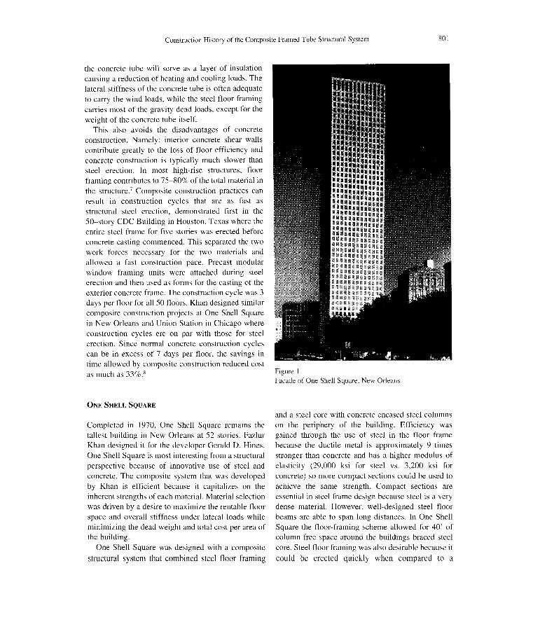
The first phase analyzed considers two floors of steelframing under wind, dead, and live load. Figure 7
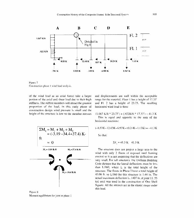
shows a free body diagram of Phase l under windload only. A joint on Column Line B has been circledin red. Moment equilibrium for this joint is checkedin Figure 8. Note that the core columns (with theexception of the central column, which carries none
Construction History of the Composite Framed Tube Structural System 80S
A
1.067 Klft
.922 Klft
8.53 K
t.781 K
Figure 7
Construction phase 1 wind load analysis
B
\ Oeta' ed inFig 8
.--12.43K
t ~5.523 K
of the wind load as an axial force) take a largerportion of the axial and shear load due to their high
stiffness. The stiffest members will attract the greatestproportion of the load. In this early phase of
construction design wind pressure is small and theheight of the structure is low so the member stresses
LMz=M¡+M2+M3
= (-3.19 -34.4+37.4) K-ft
"""O
M,=37.4 K-ftM¡=-3.19 K-ft
~.~.#T\
M,= -34.4 K-ft
Figure 8
Moment equilibrium for joint in phase I
e ED
Fl. 223.7'
Fl. 117.3'
.-- .--10.24 K8.97 K
~
.--1.13 K
~.149K 4.589 K 1.567 K
and displacements are well within the acceptablerange for the materiaL Floor I has a height of 17.33'
and Fl. 2 has a height of 23.73. The resultinghorizontal wind load is then:
(1.067 K/ft*
23.73') + (.922K/ft*
17.33') =41.3 KThis is equal and opposite to the sum of the
horizontal reactions:
(-8.53K-12.43K-8.97K-IO.24K-1.13K) = -4 1.3 K
So that:
LF, = 41.3 K - 41.3 K
The structure does not project a large area to thewind with only 2 floors of exposed steel framingerected so it is not surprising that the deflections arevery smalL For taJJ structures The Uniform Building
Code dictates that the lateral deflections must be lessthan L/360; where L is the total height of thestructure. The floors in Phase 1 have a total height of43.06 ft. so L/360 for this structure is 1.44 in. Theactual maximum deflection is .1407 in. at joint 11. 55ksi steel was used in the construction of One SheJJSquare. AJJ the stresses are in the elastic range underthis loado
806 R. A. Ellis, D. P. Billington
Phase 2
Construction Phase 2 represents the limit 01' exposedsteel erection in Qne Shell Square. A1'ter the 91hflooris erected, concreting 01' the external spandrels andcolumns begins. Temporary cable stays are used toposition steel members and stiffen the exposed steelstructure under lateralloads. Floor 3 01'Phase 2 has aheight 01' 13'. Floors 4 through 9 each have a height
01'26'.Phase II is a critical phase in the construction
sequence because it is the phase during which themaximum amount 01' steel has been left exposed. Thetcmporary cable stays are essential at this point to
limit lateral deflections under the wind load. Thelateral deflections 01' the columns are greatest in thewindward columns and decrease slightly withincreasing distance from the windward 1'ace. Phase nis 134 ft tal!. L/360 is slightly less than 5 inches 1'orthis phase. A maximum horizontal dcflection 01' 1.48»at the 91hfloor occurred in Phase n. This is acceptable.
The vertical deflections under wind are practicallynegligible
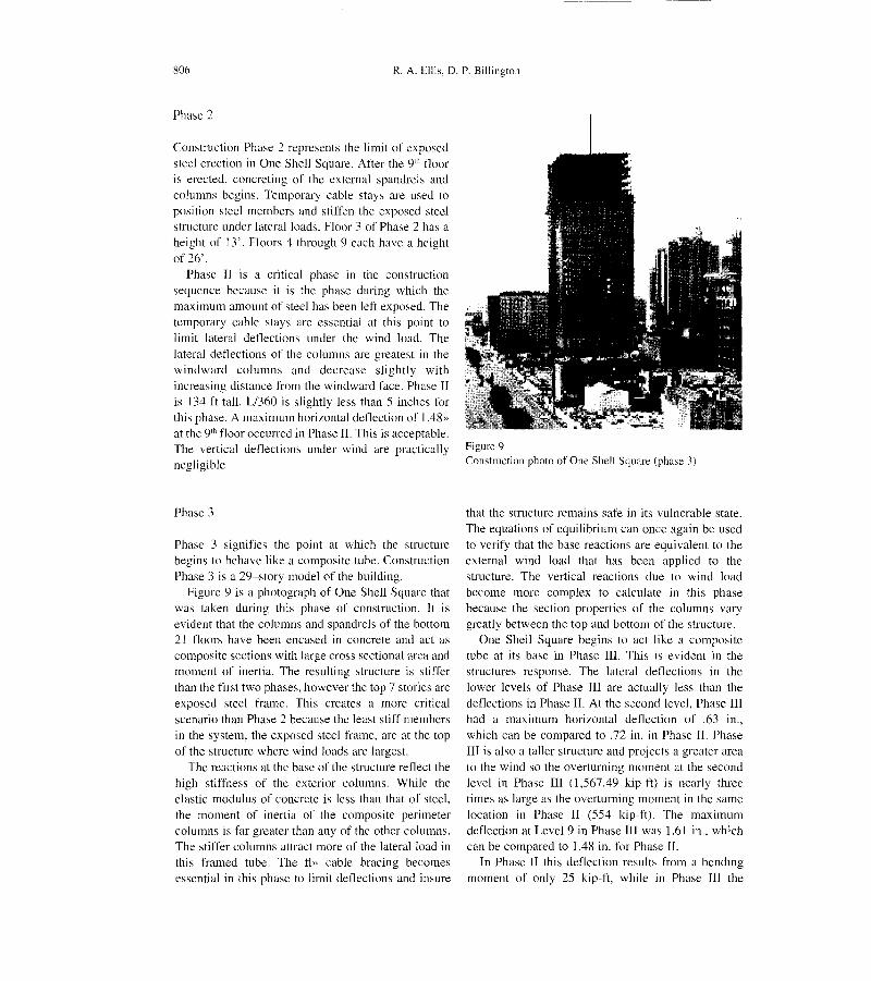
Phase 3
Phase 3 signi1'ies the point at which the structurebegins to behave like a composite tube. Construction
Phase 3 is a 29-story model 01' the building.Figure 9 is a photograph 01' Qne Shell Square that
was taken during this phase 01' construction. It isevident that the columns and spandrels 01' the bottom21 floors have been encased in concrete and act ascomposite sections with Iarge cross sectional area andmoment of inertia. The resulting structure is stif1'erthan the first two phases, however the top 7 stories areexposed steel frame. This creates a more critical
scenario than Phase 2 because the least sti1'1'membersin the system, the exposed steel frame, are at the topof the structure where wind loads are largest.
The reactions at the base of the structure reflect thehigh stiffness of the exterior columns. While the
elastic modulus 01' concrete is less than that 01' steel,the moment 01' inertia of the composite perimeterco]umns is 1'ar greater than any 01' the other columns.
The stiffer columns attract more 01' the lateral [oad inthis 1'ramed tube. The fl» cable bracing becomesessentia] in this phase to limit det1ections and insure
Figure 9Construction photo of One Shell Square (phase 3)
that the structure remains sa1'e in its vulnerable state.The equations 01'equi]ibrium can once again be used
to veri1'y that the base reactions are equivalent to theexterna] wind ]oad that has been applied to the
structure. The vertical reactions due to wind loadbecome more complex to calcu]ate in this phasebecause the section properties 01' the columns varygreatly between the top and bottom 01' the structure.
Qne Shell Square begins to act like a composite
tube at its base in Phase III. This is evident in thestructures response. The ]ateral deflections in the]ower ]evels 01' Phase III are actually less than the
det1ections in Phase n. At the second leve!. Phase IIIhad a maximum horizontal deflection 01' .63 in.,which can be compared to .72 in. in Phase n. PhasenI is a]so a taller structure and projects a greater area
to the wind so the overturning moment at the secondlevel in Phase III (1,567.49 kip-ft) is nearJy threetimes as large as the overturning moment in the samelocation in Phase ]] (554 kip-1't). The maximum
deflection at Level 9 in Phase III was 1.61 in., whichcan be compared to ].48 in. 1'or Phase n.
In Phase n this deflection results 1'rom a bendingmoment 01' on]y 25 kip-ft, whi]e in Phase III the
Construction History of the Composite Framed Tube Structural System 807
structure is responding to a moment of 575 kip-ft. Thestiff behavior in Phase III is directly attributable to thecomposite action of the columns and spandrels.
The axial stresses in the columns are also reducedas a result of the additional concrete in the lowerlevels. From Phase II to Phase III the maximum axialstress at level2 dropped from .819 ksj to .148 ksi. Thedrop in stress is due to the far larger cross-sectional
area of the composite section. The large cross-sectional area, while creating an efficient lateralsystem, is also necessary for carrying axial loads.
Concrete is ultimately not as strong as steel so thestresses in the composite sections must be less thanthe stresses in the all steel section in order for thesystem to be safe and efficient.
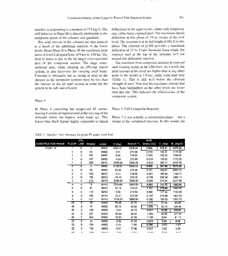
Phase 4
In Phase 4 concreting has progressed 45 stories,leaving 8 storjes of exposed steel at the very top of thestructure where the highest wind loads act. Thisleaves One Shell Square highly vulnerable to lateral
Tab1e 1. Member force summary for phase IV under wind [oad
deflections in the upper levels, where only temporarystay cables brace exposed steel. The maximum lateral
deflection in this phase of 19 in. occurs at the roofleve!. The structure is at its full height of 691 ft in thisphase. The criterion of L/360 provides a maximum
deflection of 23 in. Under hurricane force winds, theexposed steel at the top of the structure will not
exceed this deflection criterion.The transition from composite sections to exposed
steel framing occurs at the 45th floor. As a result, theaxial stresses at this level are higher than at any otherpoint in the model at 1.9 ksi, under wind load only(Table 1). This is still well below the ultimatestrength of steel. Note that the maximum stresses that
have been highlighted on the other levels are lowerthan this one. This indicates the effectiveness of thecomposite system.
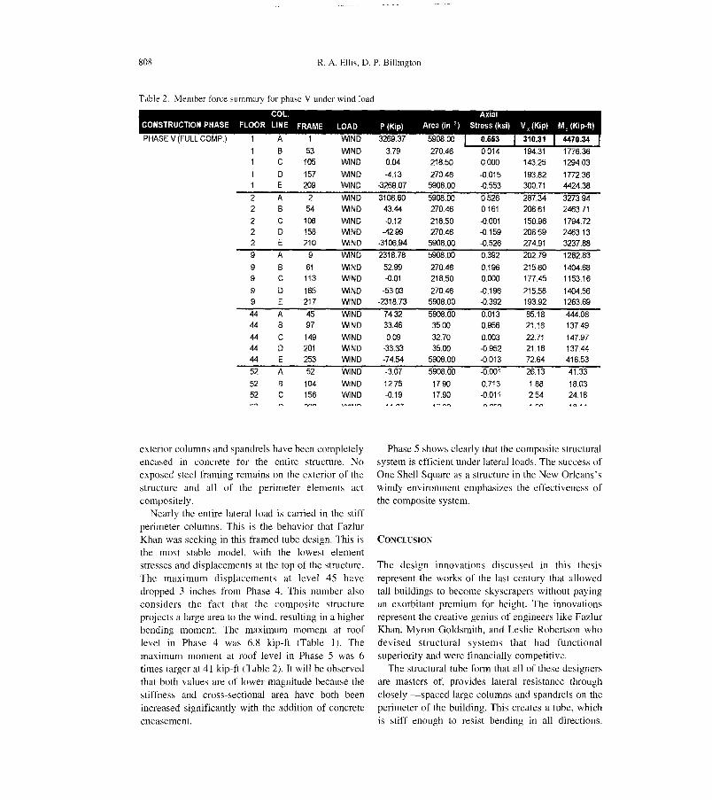
Phase 5: Full Composite Structure
Phase 5 is not actually a construction phase -but amodel of the completed structure. In this model, the
COL. AxiaJCONSTRUCTION PHASE FlOOR UNE FRAME lOAD P (Kip) Area (in ') Stress (ksi) V, (Kip) M, (Kip-ft)
P.HA'SEIV 1 A' 1 WINDI 326.- 59-0'8:.0'0' I . 310' .. I .932
3910.04
-4.24-3269 033106.t>t>
43.56
-0.11-43.10
-3106.90
2318.6953.19
000
-53.21-2318.66
55.35
65.75-0.04
-64.94-55.93
-0.385.19
-0.67
808 R. A. Ellis, D. P. Billington
Table 2. Member force summary for phase V under wind [oad
1 A 1 WlND 3269.37 5908.00 0.663 310.31 4470.341 B 53 WlND 3.79 270.46 0.014 194.31 1776361 e 105 WlND 0.04 218.50 0.000 143.25 1294.031 D 157 WlND -4.13 270.46 -0.015 193.82 1772361 E 209 WlND -3269.07 5908.00 -0553 300.71 4424.382 A 2 WlND 3108.60 5908.00 0.526 287.34 3273.942 B 54 WlND 43.44 270.46 0.161 206.61 2463.712 e 108 WlND -0.12 218.50 -0.001 150.96 1794.722 D 158 WIND -42.99 270.46 -0.159 206.59 2463132 E 210 WlND -3106.94 5908.00 -0.526 274.91 3237.889 A 9 WIND 2318.78 5908.00 0.392 202.79 1282.839 B 61 WlND 52.99 270.46 0.196 215.60 1404.689 e 113 WIND -0.01 218.50 0.000 177.45 1153.169 D 165 WlND -5303 270.46 -0.196 215.58 1404.569 E 217 WIND -2318.73 5908.00 -0392 193.92 1263.6944 A 45 WlND 7432 5908.00 0.013 85.18 444.0844 B 97 WlND 33.46 3500 0.956 21.16 137.4944 e 149 WlND 0.09 32.70 0.003 22.71 147.9744 D 201 WlND -33.33 35.00 -0.952 21.16 137.4444 E 253 WlND -74.54 5908.00 -0.013 72.64 416.5352 A 52 WlND -3.07 5908.00 -0001 26.13 41.3352 B 104 WIND 1275 17.90 0.713 1.88 180352 e 156 WlND -0.19 17.90 -0011 2.54 24.18
exterior columns and spandrels have been completelyencased in concrete for the entire structure. Noexposed steel framing remains on the exterior of the
structure and all of the perimeter elements actcompositely.
Nearly the entire lateralload is carried in the stiffperimeter columns. This is the behavior that Fazlur
Khan was seeking in this framed tube designo This isthe most stable model, with the lowest elementstresses and displacements at the top of the structure.
The maximum displacements at level 45 havedropped 3 inches from Phase 4. This number also
considers the fact that the composite structureprojects a large area to the wind, resulting in a higherbending moment. The maximum moment at roof
level in Phase 4 was 6.8 kip-ft (Table 1). Themaximum moment at roof level in Phase 5 was 6times larger at 41 kip-ft (Table 2). It wiJ] be observedthat both values are of lower magnitude because thestiftness and cross-sectional area have both been
increased significantly with the addition of concreteencasement.
Phase 5 shows clearly that the composite structuralsystem is efficient under lateralloads. The success ofOne Shell Square as a structure in the New Orleans'swindy environment emphasizes the effectiveness of
the composite system.
CONCLUSION
The design innovations discussed in this thesisrepresent the works of the last century that allowedtall buildings to become skyscrapers without payingan exorbitant premium for height. The innovationsrepresent the creative genius of engineers like FazlurKhan, Myron Goldsmith, and Leslie Robertson whodevised structural systems that had functionalsuperiority and were financially competitive.
The structural tu be form that all of these designersare masters of, provides lateral resistance throughclosely -spaced large columns and spandrels on the
perimeter of the building. This creates a tube, whichis stiff enough to resist bending in all directions.

Construction History of tbe Composite Framed Tube Structural System 809
FL 52
FL 29
L-iXI
FL9
FLI...L.193.8 -300.7 K+-- +--
t t-32694 K - 4.3 ~14 .
+-- +-- +--
-32}n -3:K ¡OK
4.13 K 3269.1 K
Figure 10
Construction phase 5 wind load analysis
Some framed-tube structures also have a core within
the exterior tube to carry some portion of the lateralload or gravity loado The stiffness of any member isproportional to its moment of inertia and inverselyproportional to its unbraced length. The framed tubegives short spans or unbraced lengths to the perimeter
columns and spandrels, resuhing in a high stiffness.The fact that the tube is on the perimeter of thebuilding means that it is as far as possible from thecentroid of the structure and has the highest momentof inertia. The Brunswick Building, World TradeCenter, and Dewitt-Chestnut Apartments are earlyexamples of framed-tube structures.
In the late 1960's another advancement was made
when Fazlur Khan designed One Shell Square in NewOrleans. The structure was to be the tallest framed-tube ever but it was also to be one of the firststructures to directly benefit from the strengths ofboth steel and concrete. Steel would be used for itsease of erection and ability to span long distances infloor framing. A steel core was erected and alightweight frame was assembled around it. Cablestays were used to po sitio n the steel and left in place
for temporary wind support. The core carried al1
lateral loads during construction while sharinggravity loads with the perimeter columns.
After erection of 8 to 10 floors the perimetercolumns and spandrels were encased in concrete.Concrete is a lighter material than steel so larger cross-sections can be used for sections before self-weightbe comes a limiting factor. Concrete sections cantherefore have larger moments of inertia than steelsections of the same weight. Placing these largesections far from the centroid of a structure serves tofurther increase their moment of inertia and theircontribution to the stiffness of the structure as a whole.
The combination of these design innovations hasal10wed engineers to build structures more quicklythat are tal1er and more cost effective. Compositeconstruction not only fully utilizes the strengths ofsteel and concrete -it minimizes their weaknesses,while the framed-tube system provides higherstiffness than is possible in a traditional frame. Theseinnovations have truly al10wed us to overcome thepremium for height. Study oí' such innovations allows
us to see how they carne into being, how individualengineers contributed to their success, and how thelocal construction constraints stimulated the searchfor such new ideas.
REFERENCE LIST
l. Gapp, Paul, «Remembering the Gentle Giant Who
Designed Sears Towef» PCI Journal, vol. 27. no. 2,
march/ApriI1982, pp. 166-7.
2. Billington, David P., The Tower and The Bridge: The
New Art al Structural Engineering. PrincetonUniversity Press, Princeton, NJ, 1983.
3. Khan, Fazlur R., «Ta11 Buildings» Skidmore, Owings &Merri11, Chicago, IIlinois, p. 2.
4. Khan, Fazlur R., «Shear Wa11 Structures» Skidmore,Owings & Merri11 , Chicago. Illinois, Presented May
23-27, 1979, Hawaii Conference, Maui, p. 3.

810 R. A. Ellis, D. P. Billington
5. Khan, Fazlur R., «Recent Development and Future ofHigh Rise Buildings», National Confáence on Tal!Buildings: Proceedings, January 22-24, 1973, New
Delhi, India, p. 117.
Khan, Fazlur R., «Evolution of Structural Systems for
High Rise Buildings in Steel and Concrete»
Proceedings: Regional Conference 0/1 Tal! Buildi/1gs,
Bratislava, Czechoslovakia, April 9-13, 1973, pp. 13-4.Iyengar, H.S., «State of the Art Report On: Composite
6.
7.
8.
or Mixed Steel-Concrete Construction for Buildings»,Report for Structural Speciflcation Liaison Committee:
American Society of Civil Engineers, New York, NewYork, 1977, pp. 69-70.Iyengar, H.S.. «State 01' the Art Report On: Composite
or Mixed Steel-Concrete Construction for Buildings»,Report for Structural Specification Liaison Committee:
American Society of Civil E/1gi/1eers.