construction materials pressure settings · the ring nut to allow access to the regulator mechanism...
TRANSCRIPT
2-IV
FR
L
Technical characteristics
Modularity, functionality and high performance are the main technical characteristics of the AIR PREPARATION
EQUIPMENT presented by UNIVER.
CONSTRUCTION MATERIALS PRESSURE SETTINGS
Main body: die-cast aluminium
Knob: ABS
Cover: ABS
Bowl: polycarbonate
Filter element: synthetic fibre
Seals: NBR
Springs: zinc plated steel
Diaphragm: fabric reinforced rubber
Ring nut: ABS
Bowl guard: ABS
OPERATING FEATURES
Functionality
The components have been manufactured to permit full
disassembly for thorough cleaning or replacement.:
- quick release bowl with bayonet connection;
- filter element inserted on the deflector and screwed on;
- automatic drain instead of manual drain for size 1 and 2.
Not provided in size 0. To replace, unscrew the ring nut
and free the drain lip, push upwards to remove, insert
replacement and re-lock;
- high rate of condensation separation: to drain use a
Ø 6 mm tube;
- the regulator knob can be easily removed by unscrewing
the ring nut to allow access to the regulator mechanism
(size 1 and 2);
- threaded gauge connection is incorporated: the codes
do not include gauges which must be ordered separately
(see page 34).
Modularity
The various parts' can be easily combined by using the
appropriate assembly kit.
The part's bodies have bore holes for wall-mounting.
The regulator can also be mounted by using a flat wall
bracket or an L-shaped wall bracket which is locked by a
ring nut under the knob and positioned in place by two
pins opposite each other which will keep it from rotating.
Pressure adjustment
Pressure, even high pressure, can easily be adjusted with
one hand only.
To adjust it, pull the knob and turn it clockwise or anti-
clockwise. When finished, push the knob upwards to block
the pressure at the level reached.
Adjust the working pressure after checking the supply
pressure.
Before performing any maintenance operation, make surethat there is no pressure in the system.
Lubrication control
Through the graduated glass bubble the oil drops can
be seen from any position.
Oil topping up
Done through the cap on the lubricator - no tools needed
(size 1 and 2).
Topping up of size 0 is done by removing the bowl with guard.
This can be done also while the system is under pressure.
Fast bowl removalThe disassembly is done by pushing the guard upwardswhile turning it one quarter to the left.The bowl comes away from the guard and presses againstthe diametrically opposite tabs.
Before removing the bowl and the guard, make surethat there is no pressure in the system.
O-ring
It is housed in the bowl which keeps it from moving and
ensures the seal.
Technical tests
The technical tests on flow and pressure were done
according to UNI - 6358 using a diaphragm measuring
instrument according to ISO - 5167.
In the catalogue pressure settings are indicated in bar.
To transform values into MPa or psi the conversion
factors are:
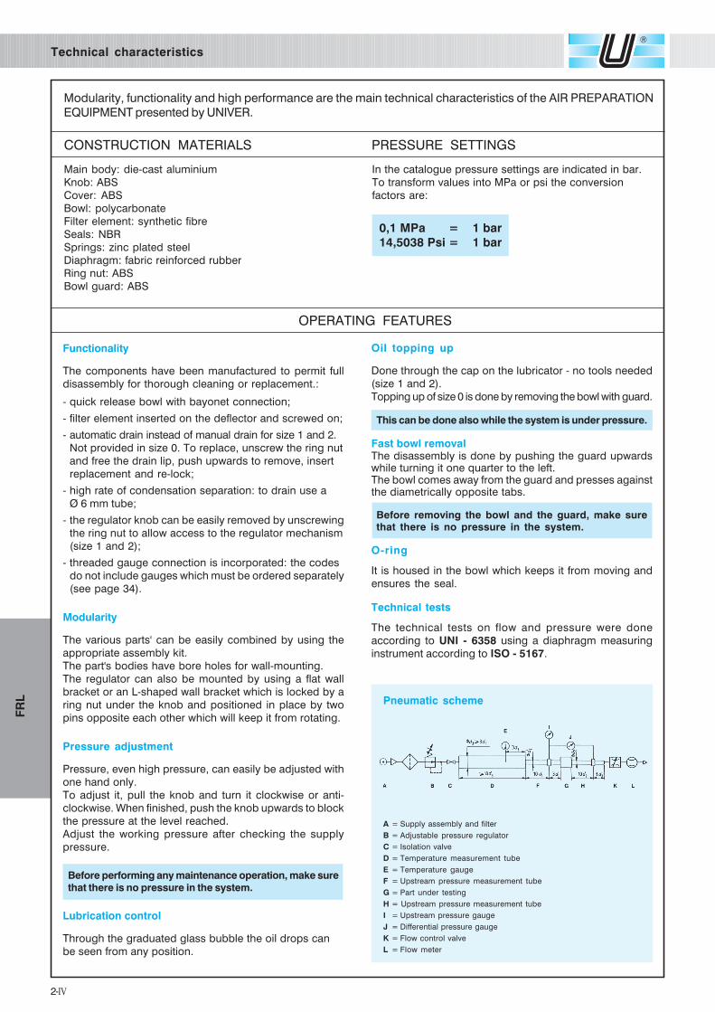
A = Supply assembly and filter
B = Adjustable pressure regulator
C = Isolation valve
D = Temperature measurement tube
E = Temperature gauge
F = Upstream pressure measurement tube
G = Part under testing
H = Upstream pressure measurement tube
I = Upstream pressure gauge
J = Differential pressure gauge
K = Flow control valve
L = Flow meter
0,1 MPa = 1 bar
14,5038 Psi = 1 bar
Pneumatic scheme
3-IV
FR
L
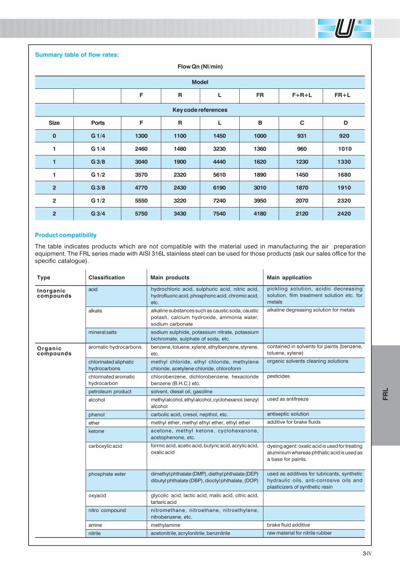
Flow Qn (NI/min)
Model
F R L FR F+R+L FR+L
Key code references
Size Ports F R L B C D
0 G 1/4 1300 1100 1450 1000 931 920
1 G 1/4 2460 1480 3230 1360 960 1010
1 G 3/8 3040 1900 4440 1620 1230 1330
1 G 1/2 3570 2320 5610 1890 1450 1680
2 G 3/8 4770 2430 6190 3010 1870 1910
2 G 1/2 5550 3220 7240 3950 2070 2320
2 G 3/4 5750 3430 7540 4180 2120 2420
Summary table of flow rates:
Type Classification Main products Main application
Inorganic acid
compounds
alkalis
mineral salts
Organic aromatic hydrocarbons
compounds
chlorinated aliphatic
hydrocarbons
chlorinated aromatic
hydrocarbon
petroleum product
alcohol
phenol
ether
ketone
carboxylic acid
phosphate ester
oxyacid
nitro compound
amine
nitrile
pickling solution, acidic decreasing
solution, film treatment solution etc. for
metals
alkaline degreasing solution for metals
contained in solvents for paints (benzene,
toluene, xylene)
organic solvents cleaning solutions
pesticides
used as antifreeze
antiseptic solution
additive for brake fluids
dyeing agent: oxalic acid is used for treating
aluminium whereas phthalic acid is used as
a base for paints.
used as additives for lubricants, synthetic
hydraulic oils, anti-corrosive oils and
plasticizers of synthetic resin
brake fluid additive
raw material for nitrile rubber
hydrochloric acid, sulphuric acid, nitric acid,
hydrofluoric acid, phosphoric acid, chromic acid,
etc.
alkaline substances such as caustic soda, caustic
potash, calcium hydroxide, ammonia water,
sodium carbonate
sodium sulphide, potassium nitrate, potassium
bichromate, sulphate of soda, etc.
benzene, toluene, xylene, ethylbenzene, styrene,
etc.
methyl chloride, ethyl chloride, methylene
chloride, acetylene chloride, chloroform
chlorobenzene, dichlorobenzene, hexacloride
benzene (B.H.C.) etc.
solvent, diesel oil, gasoline
methyl alcohol, ethyl alcohol, cyclohexanol, benzyl
alcohol
carbolic acid, cresol, nepthol, etc.
methyl ether, methyl ethyl ether, ethyl ether
acetone, methyl ketone, cyclohexanone,
acetophenone, etc.
formic acid, acetic acid, butyric acid, acrylic acid,
oxalic acid
dimethyl phthalate (DMP), diethyl phthalate (DEP)
dibutyl phthalate (DBP), dioctyl phthalate, (DOP)
glycolic acid, lactic acid, malic acid, citric acid,
tartaric acid
nitromethane, nitroethane, nitroethylene,
nitrobenzene, etc.
methylamine
acetonitrile, acrylonitrile, benznitrile
Product compatibility
The table indicates products which are not compatible with the material used in manufacturing the air preparation
equipment. The FRL series made with AISI 316L stainless steel can be used for those products (ask our sales office for the
specific catalogue).

6-IV
FR
L
HZ 1 B 08 G
Connection
Ports
Model
Size
Series
HZ = Air preparation equipment
SIZE
SERIES
0 = G 1/4
1 = G 1/4 - G 3/8 - G1/2
2 = G 3/8 - G 1/2 - G 3/4
MODEL
B = Filtrer regulator
C = F+R+L
D = B+L
F = Filter
G = Coalescing filter
L = Lubricator
M = Gradual starter
N = Diverter block
P = Lockable 3/2 valve
P S = Lockable 3/2 valve with silencer and oversize drain
R = Regulator
RL = Lockable regulator
Codification key
CONNECTIONS
08 = 1/4
10 = 3/8
15 = 1/2
20 = 3/4
PORTS
G = GAS
N = NPT (Size HZ0 excluded)
6-IV
FR
L
7-IV
FR
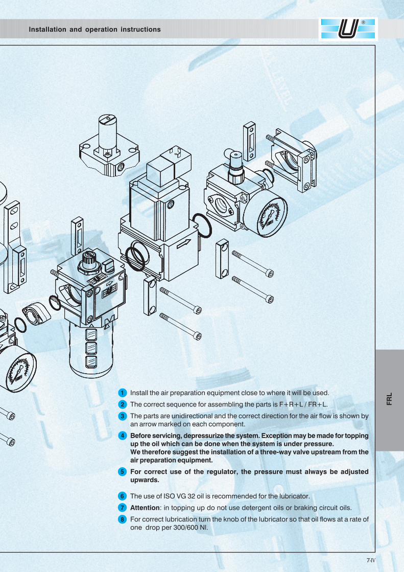
LInstall the air preparation equipment close to where it will be used.
The correct sequence for assembling the parts is F+R+L / FR+L.
The parts are unidirectional and the correct direction for the air flow is shown by
an arrow marked on each component.
Before servicing, depressurize the system. Exception may be made for topping
up the oil which can be done when the system is under pressure.
We therefore suggest the installation of a three-way valve upstream from the
air preparation equipment.
For correct use of the regulator, the pressure must always be adjusted
upwards.
The use of ISO VG 32 oil is recommended for the lubricator.
Attention: in topping up do not use detergent oils or braking circuit oils.
For correct lubrication turn the knob of the lubricator so that oil flows at a rate of
one drop per 300/600 Nl.
1
2
3
4
6
7
8
5
Installation and operation instructions
7-IV
FR
L
8-IV
FR
L
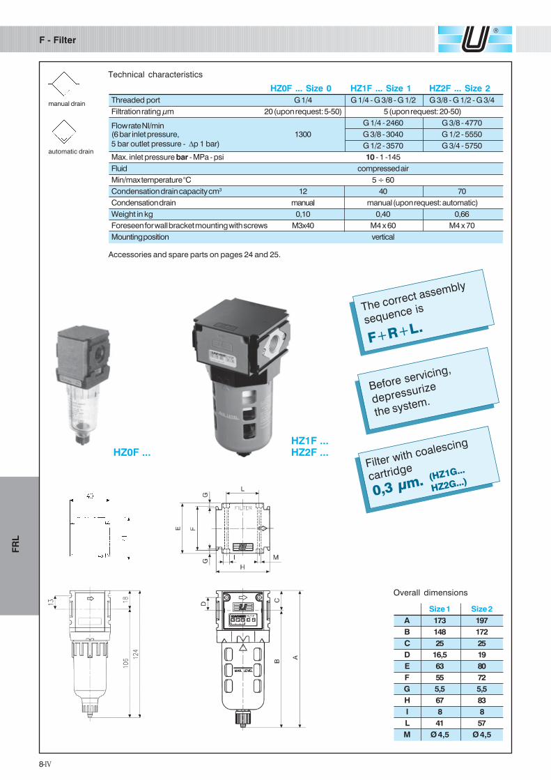
F - Filter
manual drain
automatic drain
Technical characteristics
Accessories and spare parts on pages 24 and 25.
HZ0F ... Size 0 HZ1F ... Size 1 HZ2F ... Size 2
Threaded port G 1/4 G 1/4 - G 3/8 - G 1/2 G 3/8 - G 1/2 - G 3/4
Filtration rating µm 20 (upon request: 5-50) 5 (upon request: 20-50)
Flow rate NI/min G 1/4 - 2460 G 3/8 - 4770
(6 bar inlet pressure, 1300 G 3/8 - 3040 G 1/2 - 5550
5 bar outlet pressure - ∆p 1 bar) G 1/2 - 3570 G 3/4 - 5750
Max. inlet pressure bar - MPa - psi 10 - 1 -145
Fluid compressed air
Min/max temperature °C 5 ÷ 60
Condensation drain capacity cm3 12 40 70
Condensation drain manual manual (upon request: automatic)
Weight in kg 0,10 0,40 0,66
Foreseen for wall bracket mounting with screws M3x40 M4 x 60 M4 x 70
Mounting position vertical
HZ1F ...HZ2F ...
Filter with coalescing
cartridge
0,3 µm.
F+R+L.
The correct assembly
sequence is
Overall dimensions
Size 1 Size 2
A 173 197
B 148 172
C 25 25
D 16,5 19
E 63 80
F 55 72
G 5,5 5,5
H 67 83
I 8 8
L 41 57
M Ø 4,5 Ø 4,5
HZ0F ...
Before servicing,
depressurize
the system.
(HZ1G...
HZ2G...)
9-IV
FR
L
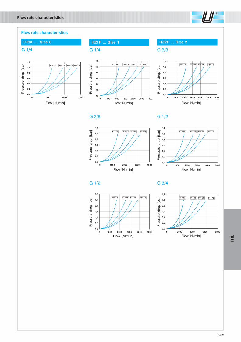
Flow rate characteristics
Flow rate characteristics
G 1/4G 1/4
G 3/8
Pre
ssu
re d
rop
[b
ar]
Flow [Nl/min]
Pre
ssu
re d
rop
[b
ar]
Flow [Nl/min]
Pre
ssu
re d
rop
[b
ar]
Flow [Nl/min]
HZ1F ... Size 1
G 3/8
G 1/2
Pre
ssu
re d
rop
[b
ar]
Flow [Nl/min]
Pre
ssu
re d
rop
[b
ar]
Flow [Nl/min]
Pre
ssu
re d
rop
[b
ar]
Flow [Nl/min]
HZ2F ... Size 2
G 3/4
G 1/4G 1/4
Pre
ssu
re d
rop
[b
ar]
Flow [Nl/min]
HZ0F ... Size 0
G 1/2
10-IV
FR
L
R - Regulator
with relieving
without relieving
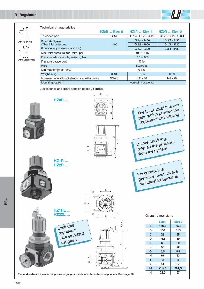
Technical characteristics
The codes do not include the pressure gauges which must be ordered separately. See page 26.
HZ1R ...HZ2R ...
Accessories and spare parts on pages 24 and 25.
For correct use,
pressure must always
be adjusted upwards.
Before servicing,
release the pressure
from the system.
The L - bracket has two
pins which prevent the
regulator from rotating.
HZ0R ... Size 0 HZ1R ... Size 1 HZ2R ... Size 2
Threaded port G 1/4 G 1/4 - G 3/8 - G 1/2 G 3/8 - G 1/2 - G 3/4
Flow rate NI/min G 1/4 - 1480 G 3/8 - 2430
(7 bar inlet pressure, 1100 G 3/8 - 1900 G 1/2 - 3220
6 bar outlet pressure - ∆p 1 bar) G 1/2 - 2320 G 3/4 - 3430
Max. inlet pressure bar - MPa - psi 10 - 1 -145
Pressure adjustment by relieving bar 0,5 ÷ 8,5
Pressure gauge port G 1/4
Fluid filtered air
Min/max temperature °C 5 ÷ 60
Weight in kg 0,10 0,55 0,93
Foreseen for wall bracket mounting with screws M3x40 M4 x 60 M4 x 70
Mounting position vertical / horizzontal
Overall dimensions
Size 1 Size 2
A 140,5 153
B 108 116
C 25 25
D 16,5 19
E 63 80
F 55 72
G 5,5 5,5
H 67 83
I 8 8
L 41 57
M Ø 4,5 Ø 4,5
N 32,5 37
HZ0R ...
Lockable
regulator:
lock standard
supplied
HZ1RL ...HZ2ZL ...

11-IV
FR
L
Flow rate and pressure characteristics
Flow rate characteristics
Special features of the UNIVER Regulator: • downstream pressure is kept constant even when upstreampressure varies • quick and responsive regulator servicing • fast elimination of downstream excess pressure.
G 1/4
Do
wn
str
ea
m p
ressu
re [
ba
r]
Flow [Nl/min]
HZ1R ... Series 1
G 3/8
Flow [Nl/min]
Do
wn
str
ea
m p
ressu
re [
ba
r]
G 1/2
Flow [Nl/min]D
ow
nstr
ea
m p
ressu
re [
ba
r]
G 1/2
Flow [Nl/min]
Do
wn
str
ea
m p
ressu
re [
ba
r]
G 3/4
Flow [Nl/min]
Do
wn
str
ea
m p
ressu
re [
ba
r]
G 3/8
Flow [Nl/min]
Do
wn
str
ea
m p
ressu
re [
ba
r]
HZ2R ... Series 2
G 1/4
Do
wn
str
ea
m p
ressu
re [
ba
r]
Flow [Nl/min]
HZ0R ... Series 0
Do
wn
str
ea
m p
ressu
re [
ba
r]
Supply pressure [bar]
Do
wn
str
ea
m p
ressu
re [
ba
r]
Supply pressure [bar]
Do
wn
str
ea
m p
ressu
re [
ba
r]
Supply pressure [bar]
Pressure characteristics
The curve shows the trend of the pressure adjusted to the changing pressure supply.
The flow rate characteristics are
obtained as follows:
1) constant supply pressure (7 bar)
2) for each pressure setting (1 - 6 bar)
the pressure reducer should be
correspondingly set at zero
pressure.
3) without adjusting the regulator,
flow is progressively increased
whilst checking downstream
pressure.
Point of departure Point of departure Point of departure

12-IV
FR
L
L - Lubricator
Accessories and spare parts on pages 24 and 25.
Technical characteristics
HZ0L ... Series 0 HZ1L ... Series 1 HZ2L ... Series 2
Threaded port G 1/4 G 1/4 - 3/8 - G 1/2 G 3/8 - G 1/2 - G 3/4
Flow rate NI/min G 1/4 - 3230 G 3/8 - 6190
(6 bar inlet pressure, 1450 G 3/8 - 4440 G 1/2 - 7240
5 bar outlet pressure - ∆p 1 bar) G 1/2 - 5610 G 3/4 - 7540
Max. inlet pressure bar - MPa - psi 10 - 1 -145
Fluid filtered air
Min/max. temperature °C 5 ÷ 60
Bowl capacity cm3 20 85 170
Weight in kg 0,10 0,40 0,65
Foreseen for wall bracket mounting with screws M3 x 40 M4 x 60 M4 x 70
Mounting position vertical
Recommended oil ISO VG 32
Minimum working flow l/min. 25 30 65
HZ1L ...HZ2L ...
HZ0L ...
Overall dimensions
Size 1 Size 2
A 170,5 195,5
B 125 149
C 25 25
D 16,5 19
E 63 80
F 55 72
G 5,5 5,5
H 67 83
I 8 8
L 41 57
M Ø 4,5 Ø 4,5
N 45,5 46,5
Prima di qualsiasi
intervento, togliere la
pressione dall'impianto.
La sequenza corretta
per l'assemblaggio è:
F+R+L / FR+L.
Before servicing,
depressurize
the system.
The correct assembly
sequence is
F+R+L / FR+L.
Oil can be topped up
when the system is
under pressure.
Recommended oil:
ISO VG 32, at the
rate of one drop per
300-600 Nl.
13-IV
FR
L
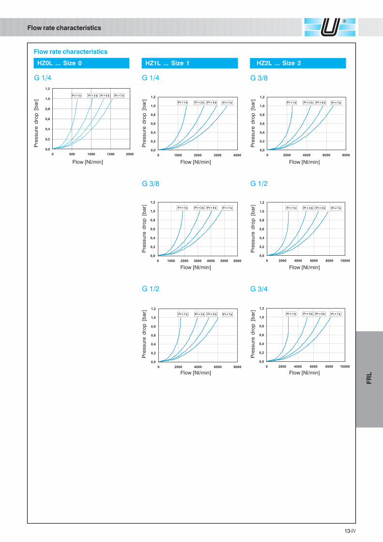
Flow rate characteristics
Flow rate characteristics
G 3/8
Pre
ssu
re d
rop
[b
ar]
Flow [Nl/min]
G 1/2
Pre
ssu
re d
rop
[b
ar]
Flow [Nl/min]
G 1/2
Pre
ssu
re d
rop
[b
ar]
Flow [Nl/min]
G 3/4
Pre
ssu
re d
rop
[b
ar]
Flow [Nl/min]
HZ1L ... Size 1
G 1/4
Pre
ssu
re d
rop
[b
ar]
Flow [Nl/min]
HZ2L ... Size 2
G 3/8
Pre
ssu
re d
rop
[b
ar]
Flow [Nl/min]
HZ0L ... Size 0
G 1/4
Pre
ssu
re d
rop
[b
ar]
Flow [Nl/min]

14-IV
FR
L
F R - Filtrer regulator
Technical characteristics
Accessories and spare parts on pages 24 and 25.
The codes do not include the pressure gauges which must be ordered separately. See page 26.
HZ0B ... Size 0 HZ1B ... Size 1 HZ2B ... Size 2
Threaded port G 1/4 G 1/4 - G 3/8 - G 1/2 G 3/8 - G 1/2 - G 3/4
Filtration rating µm 5 (upon request: 20-50)
Flow rate NI/min G 1/4 - 1360 G 3/8 - 3010
(7 bar inlet pressure, 1000 G 3/8 - 1620 G 1/2 - 3950
6 bar outlet pressure - ∆p 1 bar) G 1/2 - 1890 G 3/4 - 4180
Max. inlet pressure bar - MPa - psi 10 - 1 -145
Pressure adjustment by relieving bar 0,5÷8,5 (upon request: 0,5 ÷ 1,7 - 0,5 ÷ 3,5)
Fluid compressed air
Min/max. temperature °C 5 ÷ 60
Condensation drain capacity cm3 12 40 70
Condensation drain manual manual (upon request: automatic)
Weight in kg 0,20 0,70 1,15
Foreseen for wall bracket mounting with screws M3x40 M4 x 60 M4 x 70
Mounting position vertical
Pressure gauge port G 1/8 G 1/4
HZ1B ...HZ2B ...
Overall dimensions
Size 1 Size 2
A 256 287,5
B 148 172
C 25 25
D 16,5 19
E 63 80
F 55 72
G 5,5 5,5
H 67 83
I 8 8
L 41 57
M Ø 4,5 Ø 4,5
N 108 115,5
The L - bracket has two
pins which prevent the
FR from rotating.Before servicing,
depressurize
the system.
FR+L.
HZ0B ...
For correct use,
pressure must always
be adjusted upwards.The correct assembly
sequence is

15-IV
FR
L
Flow rate characteristics
Flow rate characteristics
G 3/8
G 3/8 G 1/2
G 1/2 G 3/4
Flow [Nl/min]
Flow [Nl/min] Flow [Nl/min]
Flow [Nl/min] Flow [Nl/min]
HZ2B ... Size 2
Do
wn
str
ea
m p
ressu
re [
ba
r]
Supply pressure [bar]
Do
wn
str
ea
m p
ressu
re [
ba
r]
Supply pressure [bar]
Do
wn
str
ea
m p
ressu
re [
ba
r]
Do
wn
str
ea
m p
ressu
re [
ba
r]
Do
wn
str
ea
m p
ressu
re [
ba
r]D
ow
nstr
ea
m p
ressu
re [
ba
r]
Do
wn
str
ea
m p
ressu
re [
ba
r]
HZ1B ... Taglia 1 HZ2B ... Taglia 2G 1/4
Do
wn
str
ea
m p
ressu
re [
ba
r]
Flow [Nl/min]
HZ1B ... Size 1
The flow rate characteristics are
obtained as follows:
1) constant supply pressure (7 bar)
2) for each pressure setting (1 - 6 bar)
the pressure reducer should be
correspondingly set at zero
pressure.
3) without adjusting the regulator,
flow is progressively increased
whilst checking downstream
pressure.
G 1/4
Do
wn
str
ea
m p
ressu
re [
ba
r]
Flow [Nl/min]
HZ0B ... Size 1
Do
wn
str
ea
m p
ressu
re [
ba
r]
Supply pressure [bar]
Pressure characteristics
The curve shows the trend of the pressure adjusted to the changing pressure
supply.
Special features of the UNIVER Regulator: • downstream pressure is kept constant even when upstreampressure varies • quick and responsive regulator servicing • fast elimination of downstream excess pressure.
Point of departure Point of departure Point of departure
16-IV
FR
L
FR+L
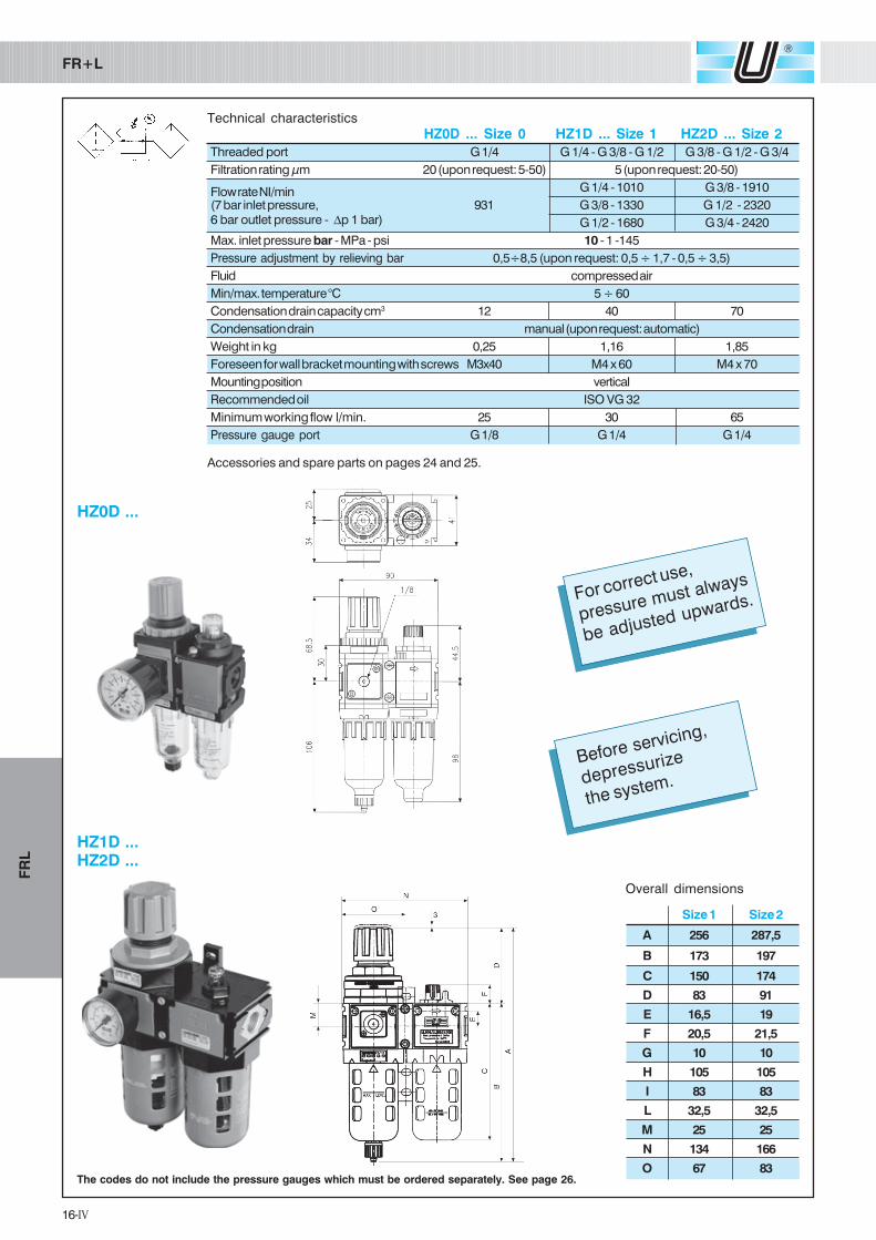
Technical characteristics
Accessories and spare parts on pages 24 and 25.
The codes do not include the pressure gauges which must be ordered separately. See page 26.
Overall dimensions
Size 1 Size 2
A 256 287,5
B 173 197
C 150 174
D 83 91
E 16,5 19
F 20,5 21,5
G 10 10
H 105 105
I 83 83
L 32,5 32,5
M 25 25
N 134 166
O 67 83
Before servicing,
depressurize
the system.
For correct use,
pressure must always
be adjusted upwards.
HZ0D ... Size 0 HZ1D ... Size 1 HZ2D ... Size 2
Threaded port G 1/4 G 1/4 - G 3/8 - G 1/2 G 3/8 - G 1/2 - G 3/4
Filtration rating µm 20 (upon request: 5-50) 5 (upon request: 20-50)
Flow rate NI/min G 1/4 - 1010 G 3/8 - 1910
(7 bar inlet pressure, 931 G 3/8 - 1330 G 1/2 - 23206 bar outlet pressure - ∆p 1 bar) G 1/2 - 1680 G 3/4 - 2420
Max. inlet pressure bar - MPa - psi 10 - 1 -145
Pressure adjustment by relieving bar 0,5÷8,5 (upon request: 0,5 ÷ 1,7 - 0,5 ÷ 3,5)
Fluid compressed air
Min/max. temperature °C 5 ÷ 60
Condensation drain capacity cm3 12 40 70
Condensation drain manual (upon request: automatic)
Weight in kg 0,25 1,16 1,85
Foreseen for wall bracket mounting with screws M3x40 M4 x 60 M4 x 70
Mounting position vertical
Recommended oil ISO VG 32
Minimum working flow l/min. 25 30 65
Pressure gauge port G 1/8 G 1/4 G 1/4
HZ1D ...HZ2D ...
HZ0D ...

17-IV
FR
L
Flow rate and pressure characteristics
Flow rate characteristics
G 3/8
G 3/8 G 1/2
G 1/2 G 3/4
Flow [Nl/min]
Flow [Nl/min] Flow [Nl/min]
Flow [Nl/min] Flow [Nl/min]
HZ2D ... Size 2
Do
wn
str
ea
m p
ressu
re [
ba
r]
Supply pressure [bar]
Do
wn
str
ea
m p
ressu
re [
ba
r]
Supply pressure [bar]
Do
wn
str
ea
m p
ressu
re [
ba
r]
Do
wn
str
ea
m p
ressu
re [
ba
r]
Do
wn
str
ea
m p
ressu
re [
ba
r]D
ow
nstr
ea
m p
ressu
re [
ba
r]
Do
wn
str
ea
m p
ressu
re [
ba
r]
HZ1B ... Taglia 1 HZ2B ... Taglia 2G 1/4
Do
wn
str
ea
m p
ressu
re [
ba
r]
Flow [Nl/min]
HZ1D ... Size 1
G 1/4
HZ0D ... Size 1
Do
wn
str
ea
m p
ressu
re [
ba
r]
Supply pressure [bar]
Pressure characteristics
The curve shows the trend of the pressure adjusted to the changing pressure
supply.
Special features of the UNIVER Regulator: • downstream pressure is kept constant even when upstreampressure varies • quick and responsive regulator servicing • fast elimination of downstream excess pressure.
The flow rate characteristics are
obtained as follows:
1) constant supply pressure (7 bar)
2) for each pressure setting (1 - 6 bar)
the pressure reducer should be
correspondingly set at zero
pressure.
3) without adjusting the regulator,
flow is progressively increased
whilst checking downstream
pressure.
Do
wn
str
ea
m p
ressu
re [
ba
r]
Flow [Nl/min]
Point of departure Point of departure Point of departure
18-IV
FR
L
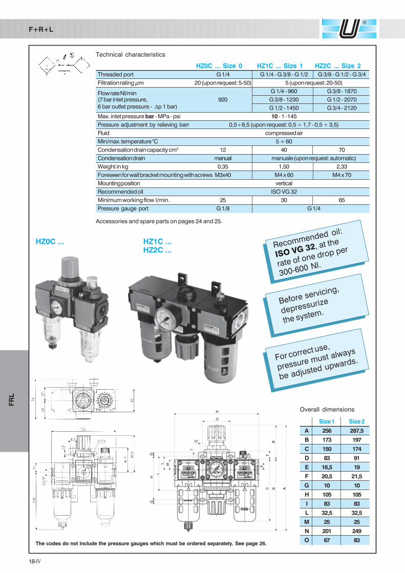
Overall dimensions
Size 1 Size 2
A 256 287,5
B 173 197
C 150 174
D 83 91
E 16,5 19
F 20,5 21,5
G 10 10
H 105 105
I 83 83
L 32,5 32,5
M 25 25
N 201 249
O 67 83
F+R+L
Technical characteristics
Accessories and spare parts on pages 24 and 25.
HZ0C ... Size 0 HZ1C ... Size 1 HZ2C ... Size 2
Threaded port G 1/4 G 1/4 - G 3/8 - G 1/2 G 3/8 - G 1/2 - G 3/4
Filtration rating µm 20 (upon request: 5-50) 5 (upon request: 20-50)
Flow rate NI/min G 1/4 - 960 G 3/8 - 1870
(7 bar inlet pressure, 920 G 3/8 - 1230 G 1/2 - 2070
6 bar outlet pressure - ∆p 1 bar) G 1/2 - 1450 G 3/4 - 2120
Max. inlet pressure bar - MPa - psi 10 - 1 -145
Pressure adjustment by relieving barr 0,5÷8,5 (upon request: 0,5 ÷ 1,7 - 0,5 ÷ 3,5)
Fluid compressed air
Min/max. temperature °C 5 ÷ 60
Condensation drain capacity cm3 12 40 70
Condensation drain manual manuale (upon request: automatic)
Weight in kg 0,35 1,50 2,33
Foreseen for wall bracket mounting with screws M3x40 M4 x 60 M4 x 70
Mounting position vertical
Recommended oil ISO VG 32
Minimum working flow l/min. 25 30 65
Pressure gauge port G 1/8 G 1/4
Before servicing,
depressurize
the system.
For correct use,
pressure must always
be adjusted upwards.
The codes do not include the pressure gauges which must be ordered separately. See page 26.
Recommended oil:
ISO VG 32, at the
rate of one drop per
300-600 Nl.
HZ1C ...HZ2C ...
HZ0C ...
19-IV
FR
L
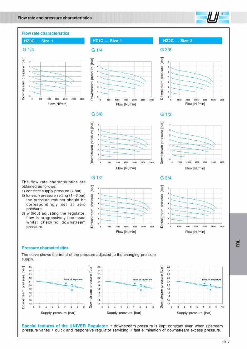
Flow rate and pressure characteristics
Flow rate characteristics
G 3/8
G 3/8 G 1/2
G 1/2 G 3/4
Flow [Nl/min]
Flow [Nl/min] Flow [Nl/min]
Flow [Nl/min] Flow [Nl/min]
HZ2C ... Size 2
Do
wn
str
ea
m p
ressu
re [
ba
r]
Supply pressure [bar]
Do
wn
str
ea
m p
ressu
re [
ba
r]
Supply pressure [bar]
Do
wn
str
ea
m p
ressu
re [
ba
r]
Do
wn
str
ea
m p
ressu
re [
ba
r]
Do
wn
str
ea
m p
ressu
re [
ba
r]D
ow
nstr
ea
m p
ressu
re [
ba
r]
Do
wn
str
ea
m p
ressu
re [
ba
r]
HZ1B ... Taglia 1 HZ2B ... Taglia 2G 1/4
Do
wn
str
ea
m p
ressu
re [
ba
r]
Flow [Nl/min]
HZ1C ... Size 1
G 1/4
Do
wn
str
ea
m p
ressu
re [
ba
r]
Flow [Nl/min]
HZ0C ... Size 1
Do
wn
str
ea
m p
ressu
re [
ba
r]
Supply pressure [bar]
Pressure characteristics
The curve shows the trend of the pressure adjusted to the changing pressure
supply.
Special features of the UNIVER Regulator: • downstream pressure is kept constant even when upstreampressure varies • quick and responsive regulator servicing • fast elimination of downstream excess pressure.
The flow rate characteristics are
obtained as follows:
1) constant supply pressure (7 bar)
2) for each pressure setting (1 - 6 bar)
the pressure reducer should be
correspondingly set at zero
pressure.
3) without adjusting the regulator,
flow is progressively increased
whilst checking downstream
pressure.
Point of departure Point of departure Point of departure
24-IV
FR
L HZ1Z210 Size 1
A B C D E F G H I J K L M
7 20 10 32,5 83 105 125 7 5 45 Ø 21 M5 x 57 38
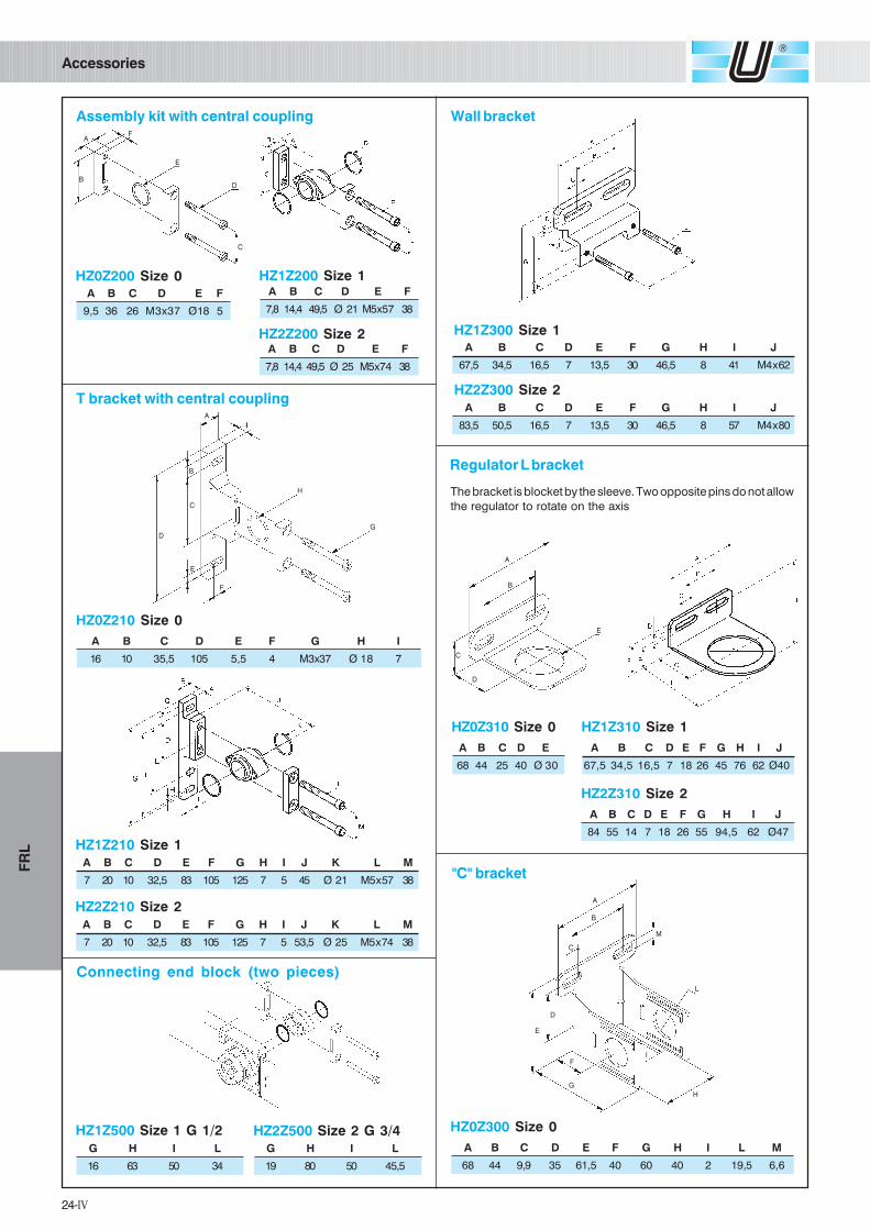
Accessories
Assembly kit with central coupling
T bracket with central coupling
Wall bracket
Regulator L bracket
HZ1Z200 Size 1
HZ2Z200 Size 2
A B C D E F
7,8 14,4 49,5 Ø 21 M5 x 57 38
A B C D E F
7,8 14,4 49,5 Ø 25 M5 x 74 38
HZ1Z300 Size 1
HZ2Z300 Size 2
A B C D E F G H I J
67,5 34,5 16,5 7 13,5 30 46,5 8 41 M4 x 62
A B C D E F G H I J
83,5 50,5 16,5 7 13,5 30 46,5 8 57 M4 x 80
HZ1Z310 Size 1
HZ2Z310 Size 2
A B C D E F G H I J
67,5 34,5 16,5 7 18 26 45 76 62 Ø40
A B C D E F G H I J
84 55 14 7 18 26 55 94,5 62 Ø47
The bracket is blocket by the sleeve. Two opposite pins do not allow
the regulator to rotate on the axis
Connecting end block (two pieces)
HZ0Z210 Size 0
A B C D E F G H I
16 10 35,5 105 5,5 4 M3x37 Ø 18 7
HZ2Z210 Size 2
A B C D E F G H I J K L M
7 20 10 32,5 83 105 125 7 5 53,5 Ø 25 M5 x 74 38
HZ0Z200 Size 0A B C D E F
9,5 36 26 M3x37 Ø18 5
B
AF
E
D
C
B
A
F
E
D
C
H
G
I
C
B
A
D
E
HZ0Z310 Size 0
A B C D E
68 44 25 40 Ø 30
HZ0Z300 Size 0
A B C D E F G H I L M
68 44 9,9 35 61,5 40 60 40 2 19,5 6,6
"C" bracket
HZ1Z500 Size 1 G 1/2 HZ2Z500 Size 2 G 3/4
G H I L
16 63 50 34
G H I L
19 80 50 45,5
B
A
F
E
D
C
H
L
M
G
I
25-IV
FR
L
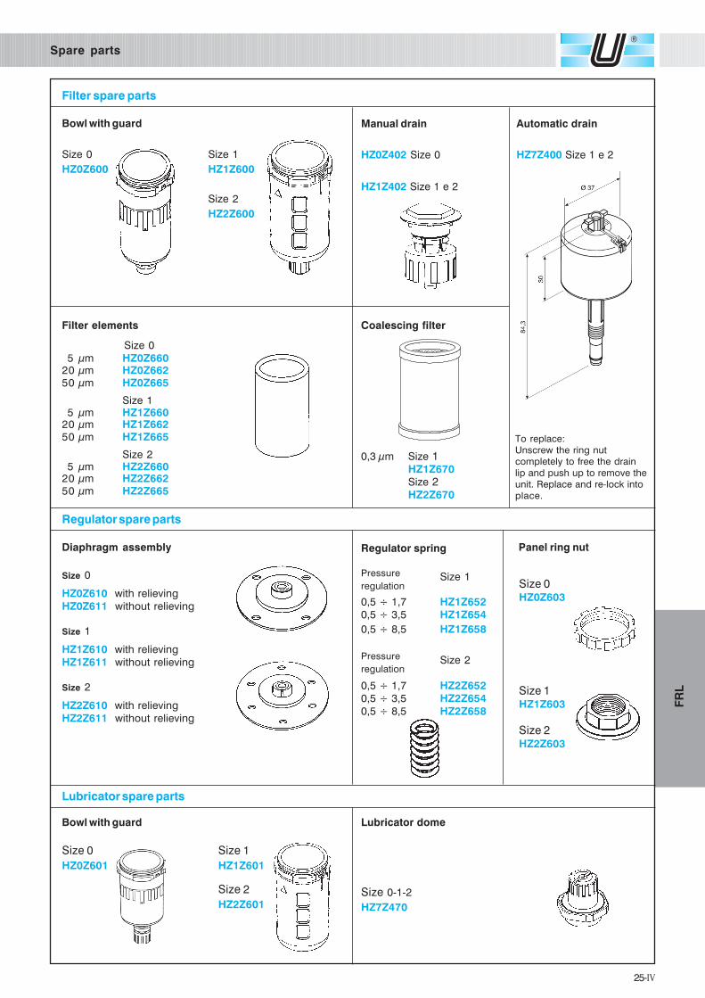
Spare parts
Filter spare parts
Bowl with guard Automatic drain
HZ7Z400 Size 1 e 2
To replace:
Unscrew the ring nut
completely to free the drain
lip and push up to remove the
unit. Replace and re-lock into
place.
Filter elements Coalescing filter
Diaphragm assembly Regulator spring
Size 1
0,5 ÷ 1,7 HZ1Z652
0,5 ÷ 3,5 HZ1Z654
0,5 ÷ 8,5 HZ1Z658
Size 2
0,5 ÷ 1,7 HZ2Z652
0,5 ÷ 3,5 HZ2Z654
0,5 ÷ 8,5 HZ2Z658
Lubricator dome
Size 0
HZ0Z610 with relieving
HZ0Z611 without relieving
Size 1
HZ1Z610 with relieving
HZ1Z611 without relieving
Size 2
HZ2Z610 with relieving
HZ2Z611 without relieving
Bowl with guard
Manual drain
HZ0Z402 Size 0
HZ1Z402 Size 1 e 2
0,3 µm Size 1HZ1Z670
Size 2HZ2Z670
Size 0
5 µm HZ0Z66020 µm HZ0Z66250 µm HZ0Z665
Size 15 µm HZ1Z660
20 µm HZ1Z66250 µm HZ1Z665
Size 25 µm HZ2Z660
20 µm HZ2Z66250 µm HZ2Z665
Regulator spare parts
Lubricator spare parts
Pressure
regulation
Pressure
regulation
Size 0
HZ0Z600
Size 0
HZ0Z601
Size 0-1-2
HZ7Z470
Panel ring nut
Size 0HZ0Z603
Size 1HZ1Z603
Size 2HZ2Z603
Size 1
HZ1Z600
Size 2
HZ2Z600
Size 1
HZ1Z601
Size 2
HZ2Z601

26-IV
FR
L
Pressure gauges
HZ9P ...Pressure gauge
HZ9PB ... Pressure gauge with flange
for planel mounting
HZ9PBS ... Pressure gauge with
bracket for planel mounting
PORT - BOURDON PIPE: Brass / Copper alloyBODY: Black ABS plasticsMOVEMENT: BrassINDICATOR: Aluminium painted blackDIAL: Pressure inserted acrylic. Polycarbonate on request.ACCURACY: EN 837 class 1,6 - 2,5. ASME B40.1 Grade BPROTECTION: IP 43
PORT - BOURDON PIPE: Brass / Copper alloyBODY: Metal painted blackASSEMBLY: Chrome-plated front flange with three holesMOVEMENT: BrassINDICATOR: Aluminium painted blackDIAL: Acrylic. Polycarbonate on request.ACCURACY: EN 837 class 1,6 - 2,5. ASME B40.1 GradePROTECTION: IP 43
PORT - BOURDON PIPE: Brass / Copper alloyBODY: Metal painted blackASSEMBLY: Fixed with back brackedMOVEMENT: BrassINDICATOR: Aluminium painted blackDIAL: Acrylic. Polycarbonate on request.ACCURACY: EN 837 class 1,6 - 2,5. ASME B40.1 GradePROTECTION: IP 43
HZ9464 Built-in pressure gauge for
Sizes 0 - 1 - 2 (0 - 10 bar)
For other types of pressure gauges please contact our sales office.
Part number Ø bar scale / MPa Port
HZ9P400318 0 - 2,5 / 0 - 0,25
HZ9P400618 40 0 - 6 / 0 - 0,6 G1/8C
HZ9P401018 0 - 10 / 0 - 1
HZ9P500314 0 - 2,5 / 0 - 0,25
HZ9P500614 50 0 - 6 / 0 - 0,6 G1/4C
HZ9P501014 0 - 10 / 0 - 1
HZ9P630314 0 - 2,5 / 0 - 0,25
HZ9P630614 63 0 - 6 / 0 - 0,6 G1/4C
HZ9P631014 0 - 10 / 0 - 1
Part number Ø bar scale / MPa Port
HZ9PB400318 0 - 2,5 / 0 - 0,25
HZ9PB400618 40 0 - 6 / 0 - 0,6 G1/8C
HZ9PB401018 0 - 10 / 0 - 1
HZ9PB500314 0 - 2,5 / 0 - 0,25
HZ9PB500614 50 0 - 6 / 0 - 0,6 G1/4C
HZ9PB501014 0 - 10 / 0 - 1
HZ9PB630314 0 - 2,5 / 0 - 0,25
HZ9PB630614 63 0 - 6 / 0 - 0,6 G1/4C
HZ9PB631014 0 - 10 / 0 - 1
Part number Ø bar scale / MPa Port
HZ9PBS400318 0 - 2,5 / 0 - 0,25
HZ9PBS400618 40 0 - 6 / 0 - 0,6 G1/8C
HZ9PBS401018 0 - 10 / 0 - 1
HZ9PBS500314 0 - 2,5 / 0 - 0,25
HZ9PBS500614 50 0 - 6 / 0 - 0,6 G1/4C
HZ9PBS501014 0 - 10 / 0 - 1
HZ9PBS630314 0 - 2,5 / 0 - 0,25
HZ9PBS630614 63 0 - 6 / 0 - 0,6 G1/4C
HZ9PBS631014 0 - 10 / 0 - 1