construction of a seepage cut-off and temporary … of a seepage cut-off and temporary retaining...
TRANSCRIPT

Construction of a Seepage Cut-Off and Temporary Retaining Wall for an Excavation in Alluvial Soils using Cutter Soil Mixing Methods
Jeff Scott, EIT Geopac Inc., Richmond, BC, Canada
Dominique Jullienne, M.Sc Geopac Inc., Richmond, BC, Canada
Fabrice Mathieu, M.Eng Soletanche Bachy, Rueil Malmaison, France
Keith Robinson, P.Eng GeoPacific Consultants Ltd., Vancouver, BC, Canada ABSTRACT The Gardens, formerly known locally as Fantasy Gardens, is a residential and commercial development located in the municipality of Richmond, British Columbia, Canada. The Gardens development consists of five low- to mid-rise buildings, with one of the buildings supported on a two level underground parking structure. The Richmond alluvial soil profile and high groundwater conditions, which are typical of the Fraser River Delta, generally require significant dewatering during the construction of excavations, in addition to treatment of all dewatering volumes prior to discharging to the local storm sewer system.
The ‘Dry Box’ solution was selected as the most appropriate technique to control the inflow of groundwater to the excavation, eliminate excessive dewatering as well as the related treatment of discharge water and allow the safe construction of the two level underground parking structure. Cutter Soil Mixing (CSM) methods were selected to construct a combined cut-off and retaining wall surrounding the excavation. This 28 m deep cut-off wall installation is recognized as one of the world’s deepest CSM applications.
This paper presents a case history describing the design, installation, QA/QC and performance related to the construction of the CSM cut-off and retaining wall at The Gardens development. A description of the CSM technique and equipment is also presented.
Introduction to CSM techniques
Cutter Soil Mixing (CSM) is a deep soil mixing method which provides a cost effective solution for the construction of cut-off and retaining walls, as well as soil improvement applications.
The CSM tool shown in Fig. 1 has been developed from diaphragm wall cutter technology and consists of counter-rotating drums fitted with sets of teeth optimised for efficiency in both cutting capacity and mixing quality between binder agents and natural soils. The Soletanche Bachy CSM tool has been designed to leave the space above the tool free, thereby mixing the soil efficiently during all phases of construction. The homogeneity of the final material is further enhanced by fixed blades set between the cutting wheels, which increases the shearing effect when mixing and ensures continuous and effective cleaning of the tool. The drums are powered by integrated compact hydraulic motors mounted on a rigid kelly-bar which allows for
excellent accuracy of both position and verticality within the in-situ soil-mixed elements. Hydraulic binder is introduced to the soil through a discharge nozzle set between the two counter-rotating drums. Fig. 1. Soletanchy Bachy CSM tool.

As shown in Fig. 2, the CSM construction process
can be described in two phases: Fig. 2. CSM two phase construction process.
(1) While drilling, the natural soil is ‘de-structured’,
broken-up and mixed with a drilling fluid (typically bentonite slurry) injected through the discharge nozzle combined with the action of two counter-rotating cutting wheels. The outward rotation of the cutting wheels displace the soil-mix above the cutting head.
(2) Upon reaching the required treatment depth, the direction of rotation of the cutting wheels are reversed and the soil is thoroughly mixed with a hydraulic binder now being injected through the discharge nozzle. The inward rotation of the cutting wheels displace the soil-mix below the cutting head, as the tool is steadily withdrawn.
Depending on the treatment depth, the drilling
fluid and binder can be of similar or entirely different materials. Drilling fluid and binder formulations are tailored for each project’s specific application and the site’s initial soil properties, such as gradation, density, cohesion, organic content, ground water elevation and even chemistry.
Typical CSM construction parameters include volume of injected drilling fluids / binders and details on the tool rotation. Penetration and withdrawal rates are also critical factors in the outcome of the final product and are directly related to the achievable compressive strength and permeability of the final soil-mixture. These installation parameters are independently controlled and recorded by a real-time monitoring system installed on the CSM rig.
The Gardens project and site description
The Gardens is a mixed-use development which covers an area of approximately 9 acres and consists of 5 buildings ranging in height from 2 to 6 stories.
Construction of the development was to be phased, with Phase 1 incorporating two buildings (Buildings A and B) in the southern half of the site.
Buildings A and B share a common single level below grade parking structure referred to as Parkade P1, with Building B founded on an underlying second level of parking structure referred to as Parkade P2. The top of parking slab elevation for Parkade P1 and P2 is -0.2 and -2.8 m geodetic respectively, approximately 1.2 and 3.8 m below initial site grades. The structures are founded on a raft type foundation with typical raft slab thickness of 600 mm.
Site description The Gardens development site is the former Fantasy Gardens exhibition site, located north of Steveston Highway, spanning between No. 5 Road and Highway 99 in Richmond, British Columbia, Canada, as illustrated in Fig 3. Fig. 3. The Gardens site location.
The City of Richmond is located on the Pacific
west coast of Canada within the Fraser River Delta. The typical surficial geology of the area is characterized by overbank silt deposits overlying deltaic sands. GeoPacific Consultants was selected as the project’s geotechnical engineer and carried out a detailed investigation of the site’s soil conditions. The soil stratigraphy, based on site geotechnical investigations, was determined to consist of some fill and topsoil, overlying low plastic silt to clay to approximately 3.5 to 4.5 m depth, grading into sandy silt, overlying compact to medium dense interbedded fine to medium clean sand to silty sand, with occasional zones of clayey silt. The sand is underlain by marine clayey silt interbedded with
1 2
Drilling Fluid
Grout

sandy silt at a depth of about 26 m, to the maximum depth of exploration of 30.5 m.
The water table at the site was determined to be approximately 0.5 to 1.0 m below initial site grades and expected to vary somewhat seasonally as well as tidally.
Following a chemical analysis of the soil and groundwater conditions, it was determined that the site groundwater did not meet aquatic life standards due to high background levels of iron and other metals. Dissolved iron concentrations were reported to vary between 20.1 and 34.5 mg/L, significantly exceeding the storm sewer and open water body discharge limit of 0.35 mg/L established by the BC Approved Water Quality Guidelines (Ministry of Environment, 2008). As a result, the groundwater is considered a pollutant and cannot be discharged to the storm sewer without some form of remedial treatment.
Development of the CSM ‘Dry Box’ solution
Construction of the two level below grade Parkade P2 at Building B required an excavation extending to elevation -3.5 m from the existing grade at about elevation +1.0 m geodetic (i.e. 4.5 m excavation depth). The high groundwater level and permeable alluvial soil conditions would necessitate extensive dewatering within the P2 excavation to allow construction to proceed, using well points and/or deep wells.
In an effort to minimize the volume of dewatering required and the associated groundwater treatment, several cut-off wall options were investigated. The cut-off wall design required enclosure around the P2 excavation limits, extending through the permeable sands and embedding into the marine silt deposit at 28 m depth.
Several cut-off wall options were considered including conventional sheet piling methods, however the CSM ‘Dry Box’ approach was selected as the most appropriate and reliable solution for this deep application.
As illustrated in Fig. 4, sufficient site area existed beyond the north, east and west boundary of the Parkade P2 foundation footprint to allow for stable cut slopes leading from the surface to the base of the 4.5 m deep P2 excavation (see Fig. 5). Along these three sides of the excavation, the CSM wall was designed to function purely as an impervious in-situ cut-off wall to restrict groundwater seepage. Here, the CSM wall was positioned to follow the alignment of the excavation perimeter at a set distance beyond the top of the cut slope to maintain slope stability.
Unlike the north, east and west boundaries, the south boundary of the Parkade P2 foundation footprint was located less than 10 m from the adjacent Steveston Highway. This site boundary constraint did not provide sufficient peripheral area to allow construction of a stable cut slope as a perimeter condition to the full depth of the excavation (see Fig. 6). To compensate for this south side condition, the CSM cut-off wall was designed to act as a temporary retaining wall to allow for a partial vertical excavation face. Fig. 4. CSM wall site plan.
The total CSM wall length measured approximately 312 m and extended to a depth of 28.0 m below working grades. A CSM wall thickness of 500 mm was selected for this application.
Cut-off wall design considerations A maximum permeability criteria of 1x10⁻⁷ m/s was specified to ensure the CSM cut-off wall provided adequate protection against groundwater seepage through the permeable sands.
A soil-mix design was developed to achieve the required permeability performance based on the site specific soil and groundwater conditions. The design was based on incorporating both bentonite and Ordinary Portland Cement (OPC) into the soil mixture. Bentonite was introduced to the soil in the form of a slurry during the ‘drill down’ phase of the CSM construction process. The OPC was introduced as a grout during the ‘grout up’ phase.
Stability of the excavation slopes along the north, east and west perimeters were ensured by maintaining the grade around the perimeter at elevation 0.0 m with a 1.25 horizontal to 1.0 vertical slope to elevation -3.5 m on the inside, as illustrated in Fig. 5 (Section A). The lateral distance between

the inside edge of the CSM wall and the crest of the slope was designed to balance the active pressure on the wall with the resisting force from the berm.
Retaining wall design considerations The south side of the CSM cut-off wall was designed to function as a temporary retaining wall to support a vertical excavation face. As illustrated in Fig. 6 (Section B), a partial slope was considered from existing surface at elevation +1.0 m down to elevation -0.9 m. This resulted in a retaining height of 2.6 m to the bottom of excavation at elevation -3.5 m.
The CSM retaining wall was based on a cantilever design where vertical steel beams were installed as reinforcement within the soil-cement mixture to resist shear stresses and bending moments imposed by lateral earth pressures. Several cantilever retaining wall designs were performed using numerical modelling software to determine the most efficient combination of section modulus, length and spacing of the vertical steel elements.
Utilizing wide flanged steel beams installed to a depth of 12.0 m below the top of the retaining wall spaced a maximum of 1.70 m on-centre was selected as the optimum solution.
The design of CSM retaining walls is based on walls with non-uniform inertia. The strength of the soil-cement mixture surrounding and between the steel reinforcement must therefore also be considered. Lateral earth pressures applied on the wall are transferred to the beams within the soil-cement mixture by an arching effect as shown in Fig 7.
Fig. 7. Compression arch in the soil-cement material between two steel beams.
The maximum compression stress and average shear stress applied to the contact section between compression arch and beams are given by the following relations:
[1] 2 · ·
[2]
The characteristic compressive strength of the
soil-cement mixture is typically taken as the maximum value between the compressive stress and 5 times the shear stress. ULS partial factors of 1.35 and 1.50 are applied to loads and material strength respectively, as per the following relations:
Fig. 5. Typical north, east and west CSM cut-off wall sections.
Fig. 6. Typical south CSM cut-off and retaining wall section adjacent to Steveston Highway.
[3] 1.35 1.5
[4] 1.35 1.5 5
can be defined for retaining walls as the 5%
fractile of the observed Unconfined Compressive Strength (UCS) distribution. Recent studies have shown that the mean compressive strength of soil-cement mixtures is related to by a ratio of 1.7, considering a log-normal distribution with a coefficient of variation equal to 30% (Mathieu et al., 2012).
It was determined that the soil-cement material required a minimum UCS of 1,000 kPa within 28 days of curing to adequately transfer the lateral earth pressures to the steel reinforcement.
Specific construction parameters such as tool rotation, extraction rates, water / cement ratios of the cement grout and grout injection rates were selected to achieve the design soil-cement mixture strength requirements. These construction parameters were determined by taking into account the cement type, groundwater level and geotechnical properties of the various soil layers within the treatment limits.
Installation of the CSM wall
Grout and slurry preparation Both the cement grout and the bentonite drilling slurry were produced on-site with an automated batching plant. The batching plant included a dry cement silo and a water tank for material storage. Cement and water quantities were measured automatically by an electronic balance controlled via the batching plant operating panel. The cement and water were blended in a turbo mixer before being transferred to an agitator tank. The agitator tank continuously stirred the prepared grout until it was ready to be pumped under a controlled flow rate and pressure to the CSM rig.
Similarly, the bentonite slurry was mixed by the batching plant before being delivered to the CSM rig. A 20,000 gallon baker tank was available for storage of the prepared slurry.
The batching plant provided electronic quality control records of the grout and slurry preparation process. The records documented the weight of water, cement and bentonite for every batch, as well as the batching start time and mixing durations.
The batching plant operator and/or quality control technician also measured the density of the cement grout using Mud Balance methods and the viscosity of the bentonite slurry using a Marsh Funnel for every batch, providing for further quality control on
the consistency of the grout and slurry when compared to mixing durations.
In addition, two sets of 3 grout samples each were collected as required for UCS testing. The grout samples were cast in moulds measuring 50 mm x 40 mm x 50 mm and sent to a third party laboratory for proper curing and UCS testing. The grout samples were tested following 14 and 28 day curing periods.
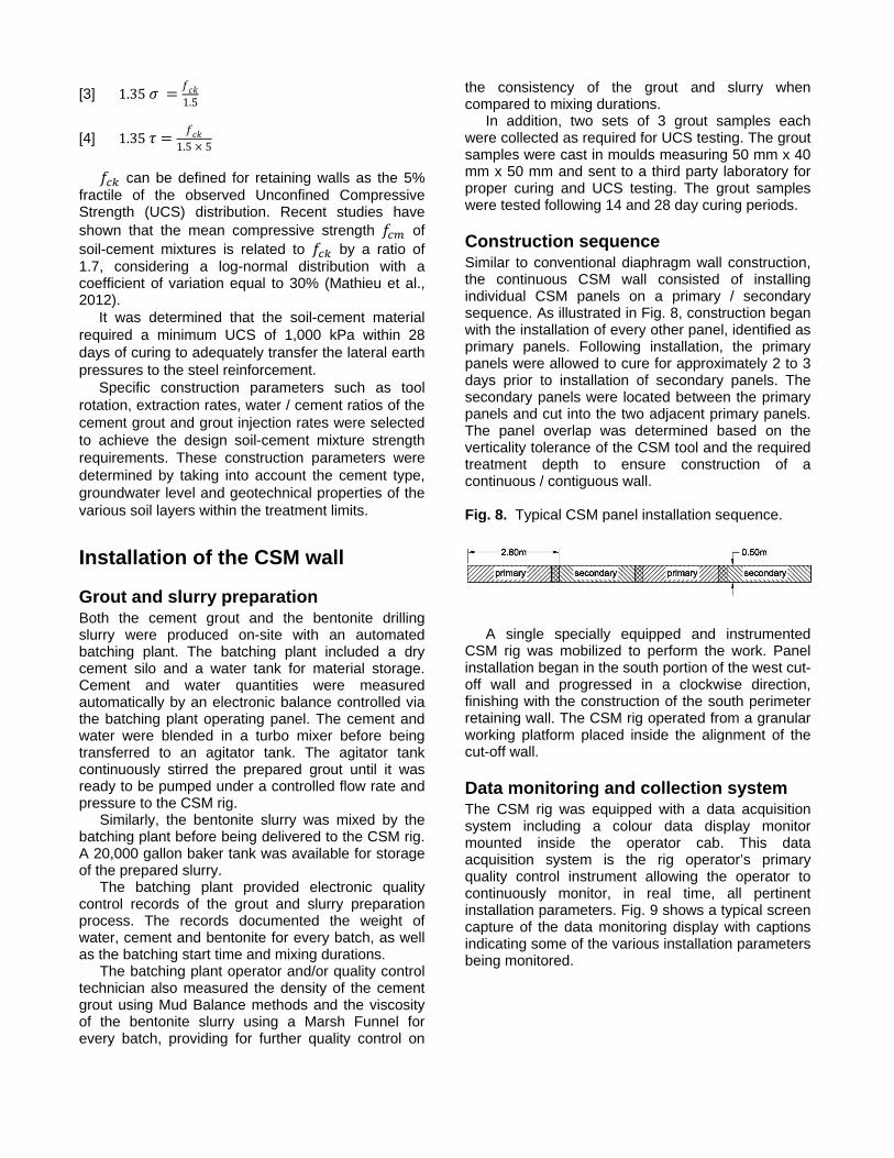
Construction sequence Similar to conventional diaphragm wall construction, the continuous CSM wall consisted of installing individual CSM panels on a primary / secondary sequence. As illustrated in Fig. 8, construction began with the installation of every other panel, identified as primary panels. Following installation, the primary panels were allowed to cure for approximately 2 to 3 days prior to installation of secondary panels. The secondary panels were located between the primary panels and cut into the two adjacent primary panels. The panel overlap was determined based on the verticality tolerance of the CSM tool and the required treatment depth to ensure construction of a continuous / contiguous wall. Fig. 8. Typical CSM panel installation sequence.
A single specially equipped and instrumented CSM rig was mobilized to perform the work. Panel installation began in the south portion of the west cut-off wall and progressed in a clockwise direction, finishing with the construction of the south perimeter retaining wall. The CSM rig operated from a granular working platform placed inside the alignment of the cut-off wall.
Data monitoring and collection system The CSM rig was equipped with a data acquisition system including a colour data display monitor mounted inside the operator cab. This data acquisition system is the rig operator’s primary quality control instrument allowing the operator to continuously monitor, in real time, all pertinent installation parameters. Fig. 9 shows a typical screen capture of the data monitoring display with captions indicating some of the various installation parameters being monitored.
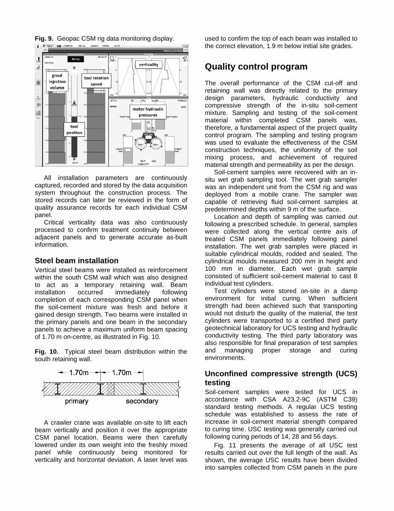
Fig. 9. Geopac CSM rig data monitoring display.
All installation parameters are continuously
captured, recorded and stored by the data acquisition system throughout the construction process. The stored records can later be reviewed in the form of quality assurance records for each individual CSM panel.
Critical verticality data was also continuously processed to confirm treatment continuity between adjacent panels and to generate accurate as-built information.
Steel beam installation Vertical steel beams were installed as reinforcement within the south CSM wall which was also designed to act as a temporary retaining wall. Beam installation occurred immediately following completion of each corresponding CSM panel when the soil-cement mixture was fresh and before it gained design strength. Two beams were installed in the primary panels and one beam in the secondary panels to achieve a maximum uniform beam spacing of 1.70 m on-centre, as illustrated in Fig. 10. Fig. 10. Typical steel beam distribution within the south retaining wall.
A crawler crane was available on-site to lift each
beam vertically and position it over the appropriate CSM panel location. Beams were then carefully lowered under its own weight into the freshly mixed panel while continuously being monitored for verticality and horizontal deviation. A laser level was
used to confirm the top of each beam was installed to the correct elevation, 1.9 m below initial site grades.
Quality control program
The overall performance of the CSM cut-off and retaining wall was directly related to the primary design parameters, hydraulic conductivity and compressive strength of the in-situ soil-cement mixture. Sampling and testing of the soil-cement material within completed CSM panels was, therefore, a fundamental aspect of the project quality control program. The sampling and testing program was used to evaluate the effectiveness of the CSM construction techniques, the uniformity of the soil mixing process, and achievement of required material strength and permeability as per the design.
Soil-cement samples were recovered with an in-situ wet grab sampling tool. The wet grab sampler was an independent unit from the CSM rig and was deployed from a mobile crane. The sampler was capable of retrieving fluid soil-cement samples at predetermined depths within 9 m of the surface.
Location and depth of sampling was carried out following a prescribed schedule. In general, samples were collected along the vertical centre axis of treated CSM panels immediately following panel installation. The wet grab samples were placed in suitable cylindrical moulds, rodded and sealed. The cylindrical moulds measured 200 mm in height and 100 mm in diameter. Each wet grab sample consisted of sufficient soil-cement material to cast 8 individual test cylinders.
Test cylinders were stored on-site in a damp environment for initial curing. When sufficient strength had been achieved such that transporting would not disturb the quality of the material, the test cylinders were transported to a certified third party geotechnical laboratory for UCS testing and hydraulic conductivity testing. The third party laboratory was also responsible for final preparation of test samples and managing proper storage and curing environments.
Unconfined compressive strength (UCS) testing Soil-cement samples were tested for UCS in accordance with CSA A23.2-9C (ASTM C39) standard testing methods. A regular UCS testing schedule was established to assess the rate of increase in soil-cement material strength compared to curing time. USC testing was generally carried out following curing periods of 14, 28 and 56 days.
Fig. 11 presents the average of all USC test results carried out over the full length of the wall. As shown, the average USC results have been divided into samples collected from CSM panels in the pure

cut-off wall sections and in the retaining wall section. On average, the minimum required compressive strength of 1,000 kPa after 28 days of curing was satisfied for all wall sections. In the more critical retaining wall section, the soil-cement material measured sufficient strength even after 14 days, and the mixture continued to gain strength up to approximately 1,500 kPa after 56 days of curing. Fig. 11. Average of all UCS results from soil-cement wet grab sampling.
Hydraulic conductivity testing Soil-cement samples were also collected for hydraulic conductivity testing to ensure the material achieved the design permeability requirements. Similar to the UCS testing, the samples were collected using the same wet grab sampling methods and cast into the same cylindrical moulds measuring 200 mm in height and 100 mm in diameter. The samples were allowed to cure for a minimum of 28 days before being tested by a third party laboratory.
The hydraulic conductivity tests were performed using falling head testing methods. In general, permeability measurements were recorded on a daily basis for an average testing duration of approximately 25 days.
The hydraulic conductivity testing demonstrated all tests achieved the design performance requirement of 1x10⁻⁷ m/s maximum permeability. The average permeability measurement for all completed hydraulic conductivity tests was approximately 3.9x10⁻⁸ m/s.
Effectiveness of the CSM ‘Dry Box’ solution
Excavation for the P1 and P2 parkade was permitted following confirmation from laboratory testing that the
soil-cement material had achieved the permeability and compressive strength requirements. The excavation operations were staged and generally coordinated to follow the same sequence of operations as the CSM wall construction. This ensured any excavation up to, or adjacent to, individual CSM panels occurred following the recommended minimum duration of 28 days after panel installation.
In addition to the UCS and hydraulic conductivity testing on wet grab soil-cement samples, further assessment of the overall performance of the CSM cut-off wall was based on the volume of groundwater inflow into the excavation. Following completion of the excavation, and after draining the contained water above the excavation base, it was apparent the groundwater inflow was much less than the estimated 50 gpm that would inflow under or through the cut-off wall based on the design parameters. Only a single submersible pump was required within the excavation base for decanting due in part to precipitation and surface runoff. It was estimated that the actual groundwater inflow was in the order of 10 gpm. It was therefore concluded the cut-off wall had been successfully constructed as designed and functioned well.
Following excavation to the southern perimeter limits, where the retaining wall section was constructed, a visual inspection of the exposed upper 4 m of the CSM wall was conducted. It was visually apparent the CSM process produced a very consistent and homogeneous soil-cement material without silt or sand inclusions of noticeable size. Excavation of the retaining wall also revealed the steel beams’ outer-flange surface facing the inside of the excavation. Visual inspection verified the beams were consistently plumb, installed in the correct position and to required design elevation. Fig. 12 shows the retaining wall following completion of the excavation looking south towards Steveston Highway. The photo shows the steel beams installed in the retaining wall, as well as the dry base of the excavation which remained free of water during foundation construction.
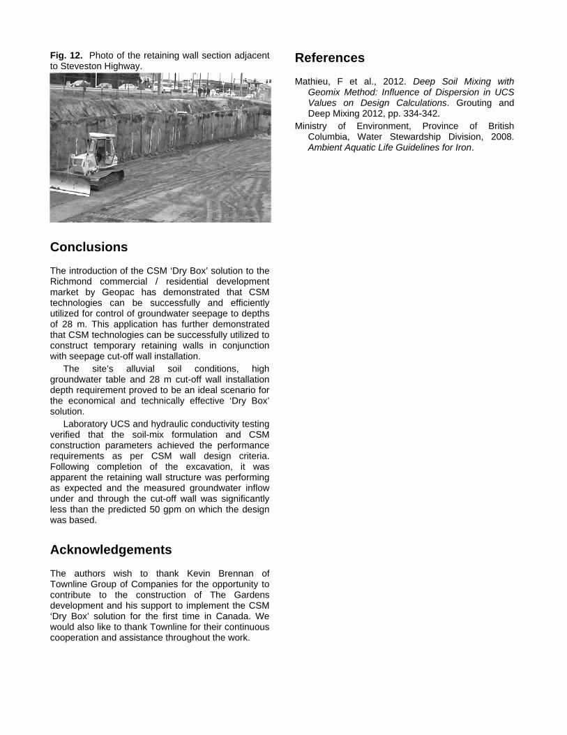
Fig. 12. Photo of the retaining wall section adjacent to Steveston Highway.
Conclusions
The introduction of the CSM ‘Dry Box’ solution to the Richmond commercial / residential development market by Geopac has demonstrated that CSM technologies can be successfully and efficiently utilized for control of groundwater seepage to depths of 28 m. This application has further demonstrated that CSM technologies can be successfully utilized to construct temporary retaining walls in conjunction with seepage cut-off wall installation.
The site’s alluvial soil conditions, high groundwater table and 28 m cut-off wall installation depth requirement proved to be an ideal scenario for the economical and technically effective ‘Dry Box’ solution.
Laboratory UCS and hydraulic conductivity testing verified that the soil-mix formulation and CSM construction parameters achieved the performance requirements as per CSM wall design criteria. Following completion of the excavation, it was apparent the retaining wall structure was performing as expected and the measured groundwater inflow under and through the cut-off wall was significantly less than the predicted 50 gpm on which the design was based.
Acknowledgements
The authors wish to thank Kevin Brennan of Townline Group of Companies for the opportunity to contribute to the construction of The Gardens development and his support to implement the CSM ‘Dry Box’ solution for the first time in Canada. We would also like to thank Townline for their continuous cooperation and assistance throughout the work.
References
Mathieu, F et al., 2012. Deep Soil Mixing with Geomix Method: Influence of Dispersion in UCS Values on Design Calculations. Grouting and Deep Mixing 2012, pp. 334-342.
Ministry of Environment, Province of British Columbia, Water Stewardship Division, 2008. Ambient Aquatic Life Guidelines for Iron.